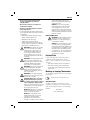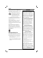
1
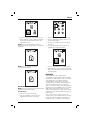
www.
.eu
DCT416
Figure 1
a
Figure 2
c
f, g
j
h
b
m
i
d, e
l
k
e
d
a
Figure 4
Figure 3
a
o
n
p
1
ENGLISH
CORDLESS IMAGING THERMOMETER
DCT416
Congratulations!
You have chosen a DEWALT tool. Years of
experience, thorough product development and
innovation make DEWALT one of the most reliable
partners for professional power tool users.
Technical Data
Voltage
Type
Battery type
Screen size
DCT416
10.8
1
Li-Ion
mm
55.9
Color TFT LCD with Backlight
VDC
Weight
(without battery pack) kg
0.5
Run-Time
Approx. 10 hours
Temperature Range
-5 ˚C to 45 ˚C (23 ˚F to 113 ˚F)
(Operating)
Temperature Range
-20 ˚C to 60 ˚C (-4 ˚F to 140 ˚F)
(Storage)
Temperature
-10 ˚C to 250 ˚C (14 ˚F to 480 ˚F)
Measurement Range
Relative Humidity
10 to 90%, non-condensing
Spectral Response
8μm to 12μm
Field of View
20˚ x 20˚
IFOV (Instantaneuos
25 mm at 1 m (1" at 39.3")
Field of View)
Accuracy
Below 100 ˚C (212 ˚F) +/- 2 ˚C (+/- 3.6 ˚F)
Above 100 ˚C (212 ˚F) +/- 2 ˚C (+/- 3.6 ˚F)
of reading. Ambient temperature for stated
accuracy 23 ˚C (73.4 ˚F).
Emissivity
0.1 to 1.0, adjustable in 0.01
increments
Temperature scales
˚C or ˚F
Battery pack
Battery type
Voltage
VDC
Capacity
Ah
Weight
kg
DCB121
Li-Ion
10.8
1.3
0.2
DCB123
Li-Ion
10.8
1.5
0.2
Charger
DCB100
230
Mains voltage VAC
Battery type
Li-Ion
Approx.
min
40
40
charging
(1.3 Ah
(1.5 Ah
time
battery
battery
packs)
packs)
Weight
kg
0.3
Fuses
Europe
U.K. & Ireland
230 V tools
230 V tools
DCB105
230
Li-Ion
30
30
(1.3 Ah (1.5 Ah
battery
battery
packs)
packs)
0.49
10 Amperes, mains
3 Amperes, in plugs
WARNING: This is a Class A product.
In a domestic environment this product
may cause radio interference in which
case the user may be required to take
adequate measures.
WARNING: Increased electrostatic
voltage may cause display to fail and all
unsaved data will be lost. If the screen
freezes, remove the 10.8 V battery pack
to reset the unit. Reinsert the battery
pack and press the power on button.
Definitions: Safety Guidelines
The definitions below describe the level of severity
for each signal word. Please read the manual and
pay attention to these symbols.
DANGER: Indicates an imminently
hazardous situation which, if not avoided,
will result in death or serious injury.
WARNING: Indicates a potentially
hazardous situation which, if not
avoided, could result in death or
serious injury.
CAUTION: Indicates a potentially
hazardous situation which, if not
avoided, may result in minor or
moderate injury.
NOTICE: Indicates a practice not
related to personal injury which, if
not avoided, may result in property
damage.
33
EN GLI S H
Denotes risk of electric shock.
b)
Denotes risk of fire.
WARNING: To reduce the risk of injury,
read the instruction manual.
Important Safety Instructions
• Read these instructions.
• Keep these instructions.
• Heed all warnings.
Battery Tool Use and Care
a)
• Follow all instructions.
• Only use attachments/accessories specified by
the manufacturer.
b)
• Refer all servicing to qualified service personnel.
Servicing is required when the apparatus has
been damaged in any way, the apparatus has
been exposed to rain or moisture, does not
operate normally, or has been dropped.
SAVE ALL WARNINGS AND INSTRUCTIONS FOR
FUTURE REFERENCE
Work Area Safety
a)
b)
Keep work area clean and well lit.
Cluttered or dark areas invite accidents.
Keep children and bystanders
away while operating an imaging
thermometer. Distractions can cause you to
lose control.
Personal Safety
a)
b)
Stay alert, watch what you are doing
and use common sense when operating
an imaging thermometer. Do not use an
imaging thermometer while you are tired
or under the influence of drugs, alcohol
or medication. A moment of inattention
while operating the imaging thermometer.
may result in serious personal injury.
Do not overreach. Keep proper footing
and balance at all times. This enables
better control of the imaging thermometer in
unexpected situations.
Use and Care
a)
34
Store an idle imaging thermometer out
of the reach of children and do not allow
persons unfamiliar with the imaging
thermometer or these instructions to
operate the imaging thermometer. The
imaging thermometer may be dangerous in
the hands of untrained users.
Use the imaging thermometer,
accessories, etc. in accordance with
these instructions, taking into account
the working conditions and the work
to be performed. Use of the imaging
thermometer for operations different from
those intended could result in a hazardous
situation.
c)
Recharge only with the charger
specified by DEWALT. A charger that is
suitable for one type of battery pack may
create a risk of fire when used with another
battery pack.
When battery pack is not in use, keep it
away from other metal objects like paper
clips, coins, keys, nails, screws, or other
small metal objects that can make a
connection from one terminal to another.
Shorting the battery terminals together may
cause burns or a fire.
Under abusive conditions, liquid may
be ejected from the battery; avoid
contact. If contact accidentally occurs,
flush with water. If liquid contacts eyes,
additionally seek medical help. Liquid
ejected from the battery may cause irritation
or burns.
Safety Information for Imaging
Thermometers
WARNING: Do not disassemble or
modify the imaging thermometer.
There are no serviceable parts
inside. If you need assistance, contact
your local dealer.
• Do not operate the imaging thermometer
in explosive atmospheres, such as in the
presence of flammable liquids, gases, or
dust. Imaging thermometers create sparks
which may ignite the dust or fumes.
• The imaging thermometer should only be
used with specifically designated DEWALT
batteries. Use of any other batteries may
create a risk of fire.
• Store the imaging thermometer out of
reach of children and other untrained
persons. Tools are dangerous in the hands of
untrained users.
• Do not remove or deface warning labels.
ENGLISH
• Do not use imaging thermometer for
testing temperatures of cooked or
uncooked food.
operate the imaging thermometer
within the operating range noted in the
specification chart.
• Do not touch surfaces to confirm hot
temperature readings.
NOTICE: Do not point the imaging
thermometer (with or without the lens
cover engaged) at the sun or other
intensive energy sources that emit laser
radiation. This can damage the detector
inside the imaging thermometer and can
effect the accuracy.
• Do not use for taking human or animal
body temperatures.
• To avoid damaging the imaging thermometer
or the equipment under test, protect them from
the following:
– EMF (electromagnetic fields) like from arc
welders, induction heaters, etc.
MICRO SD MEMORY CARD
WARNING: Choking hazard. The micro
SD memory card is a small part that
could lead to a choking hazard and is
not intended for children.
– ESD (electrostatic discharge).
– Thermal shock (caused by abrupt
ambient temperature changes for highest
accuracy; allow 30 minutes for the imaging
thermometer to stabilize before use).
WARNING: Burn hazard. The reading
may not be accurate if the imaging
thermometer is in the presence of
strong electromagnetic fields (such
as arc welders, induction heaters,
ratio transmitters, etc.). Do not use
the imaging thermometer under these
conditions.
WARNING: The imaging thermometer
measures surface temperature only.
Objects behind the surface may have
significantly different temperatures,
posing a burn or frostbite hazard.
WARNING: See emissivity information
for actual temperatures. Reflective
objects result in lower than actual
temperature measurements and can
pose a burn hazard.
WARNING: Do not expose imaging
thermometer to excessive heat such as
sunshine, fire or the like.
CAUTION: When not in use, place
imaging thermometer on its side
on a stable surface where it will not
cause a tripping or falling hazard.
Some tools with large battery packs will
stand upright on the battery pack but
may be easily knocked over.
NOTICE: Modifications not authorised
by the manufacturer may void user’s
authority to operate this device.
NOTICE: It is recommended to use the
micro SD memory card supplied with
the imaging thermometer. DEWALT does
not warrant the use or reliability of other
aftermarket cards with different brands
or capacities. It is also recommended to
frequently transfer the saved images to
a computer as a backup.
Residual Risks
In spite of the application of the relevant safety
regulations and the implementation of safety
devices, certain residual risks cannot be avoided.
These are:
– Risk of personal injury due to prolonged use.
– Risk of personal injury due to unintentional
contact with current-carrying parts during the
work process.
Markings on Imaging Thermometer
The following pictograms are shown on the imaging
thermometer:
Read instruction manual before use.
DATE CODE POSITION
The date code, which also includes the year of
manufacture, is printed into the housing surface that
forms the mounting joint between tool and battery.
Example:
2012 XX XX
Year of Manufacture
NOTICE: To avoid damage to the
imaging thermometer, do not leave
it exposed to high temperature
environments or heat sources, for
example, in a vehicle in the sun. Always
35
EN GLI S H
Important Safety Instructions for All
Battery Chargers
SAVE THESE INSTRUCTIONS: This manual
contains important safety and operating instructions
for the DCB100 and DCB105 battery chargers.
• Before using charger, read all instructions and
cautionary markings on charger, battery pack,
and product using battery pack.
WARNING: Shock hazard. Do not allow
any liquid to get inside charger. Electric
shock may result.
CAUTION: Burn hazard. To reduce
the risk of injury, charge only DEWALT
rechargeable batteries. Other types of
batteries may burst causing personal
injury and damage.
CAUTION: Children should be
supervised to ensure that they do not
play with the appliance.
NOTICE: Under certain conditions, with
the charger plugged in to the power
supply, the charger can be shorted by
foreign material. Foreign materials of
a conductive nature such as, but not
limited to, grinding dust, metal chips,
steel wool, aluminum foil, or any buildup
of metallic particles should be kept away
from charger cavities. Always unplug the
charger from the power supply when
there is no battery pack in the cavity.
Unplug charger before attempting to
clean.
• Do not place any object on top of charger
or place the charger on a soft surface that
might block the ventilation slots and result
in excessive internal heat. Place the charger
in a position away from any heat source. The
charger is ventilated through slots in the top and
the bottom of the housing.
• Do not operate charger with damaged cord
or plug — have them replaced immediately.
• Do not operate charger if it has received
a sharp blow, been dropped, or otherwise
damaged in any way. Take it to an authorised
service centre.
• Do not disassemble charger; take it to an
authorised service centre when service or
repair is required. Incorrect reassembly may
result in a risk of electric shock, electrocution or
fire.
• In case of damaged power supply cord the
supply cord must be replaced immediately by
the manufacturer, its service agent or similar
qualified person to prevent any hazard.
• Disconnect the charger from the outlet
before attempting any cleaning. This will
reduce the risk of electric shock. Removing
the battery pack will not reduce this risk.
• NEVER attempt to connect 2 chargers together.
• The charger is designed to operate on
standard 230 V household electrical power.
Do not attempt to use it on any other
voltage. This does not apply to the vehicular
charger.
SAVE THESE INSTRUCTIONS
• DO NOT attempt to charge the battery pack
with any chargers other than the ones in
this manual. The charger and battery pack are
specifically designed to work together.
Chargers
• These chargers are not intended for
any uses other than charging DEWALT
rechargeable batteries. Any other uses
may result in risk of fire, electric shock or
electrocution.
These chargers require no adjustment and are
designed to be as easy as possible to operate.
• Do not expose charger to rain or snow.
• Pull by plug rather than cord when
disconnecting charger. This will reduce risk
of damage to electric plug and cord.
• Make sure that cord is located so that it
will not be stepped on, tripped over, or
otherwise subjected to damage or stress.
• Do not use an extension cord unless it
is absolutely necessary. Use of improper
extension cord could result in risk of fire,
electric shock, or electrocution.
36
The DCB100 and DCB105 chargers accept 10.8 V
Li-Ion batteries.
Charging Procedure (fig. 1)
1. Plug the charger into an appropriate outlet
before inserting battery pack.
2. Insert the battery pack (a) into the charger.
The red (charging) light will blink continuously
indicating that the charging process has started.
3. The completion of charge will be indicated by
the red light remaining ON continuously. The
pack is fully charged and may be used at this
time or left in the charger.
ENGLISH
NOTE: To ensure maximum performance and life of
Li-Ion batteries, charge the battery pack fully before
first use.
Charging Process
Refer to the table below for the state of charge of
the battery pack.
State of charge
charging
fully charged
hot/cold pack delay
replace battery pack
– – – –
–––––––––––
–– – –– –
•••••••••••
Hot/Cold Pack Delay
When the charger detects a battery that is too hot
or too cold, it automatically starts a Hot/Cold Pack
Delay, suspending charging until the battery has
reached an appropriate temperature. The charger
then automatically switches to the pack charging
mode. This feature ensures maximum battery life.
LI-ION BATTERY PACKS ONLY
Li-Ion batteries are designed with an Electronic
Protection System that will protect the battery
against overloading, overheating or deep discharge.
The tool will automatically turn off if the Electronic
Protection System engages. If this occurs, place the
Li-Ion battery on the charger until it is fully charged.
Important Safety Instructions for All
Battery Packs
When ordering replacement battery packs, be sure
to include catalog number and voltage.
The battery pack is not fully charged out of the
carton. Before using the battery pack and charger,
read the safety instructions below. Then follow
charging procedures outlined.
READ ALL INSTRUCTIONS
• Do not charge or use battery in explosive
atmospheres, such as in the presence of
flammable liquids, gases or dust. Inserting
or removing the battery from the charger may
ignite the dust or fumes.
• Never force battery pack into charger. Do
not modify battery pack in any way to fit into
a non-compatible charger as battery pack
may rupture causing serious personal injury.
• Do not store or use the tool and battery
pack in locations where the temperature
may reach or exceed 40 ˚C (105 ˚F) (such as
outside sheds or metal buildings in summer).
WARNING: Never attempt to open the
battery pack for any reason. If battery
pack case is cracked or damaged,
do not insert into charger. Do not
crush, drop or damage battery pack.
Do not use a battery pack or charger
that has received a sharp blow, been
dropped, run over or damaged in any
way (i.e., pierced with a nail, hit with a
hammer, stepped on). Electric shock
or electrocution may result. Damaged
battery packs should be returned to
service centre for recycling.
CAUTION: When not in use, place
tool on its side on a stable surface
where it will not cause a tripping or
falling hazard. Some tools with large
battery packs will stand upright on the
battery pack but may be easily knocked
over.
SPECIFIC SAFETY INSTRUCTIONS FOR LITHIUM ION
(Li-Ion)
• Do not incinerate the battery pack even if it
is severely damaged or is completely worn
out. The battery pack can explode in a fire.
Toxic fumes and materials are created when
lithium ion battery packs are burned.
• If battery contents come into contact with
the skin, immediately wash area with mild
soap and water. If battery liquid gets into the
eye, rinse water over the open eye for
15 minutes or until irritation ceases. If medical
attention is needed, the battery electrolyte
is composed of a mixture of liquid organic
carbonates and lithium salts.
• Contents of opened battery cells may cause
respiratory irritation. Provide fresh air. If
symptoms persist, seek medical attention.
WARNING: Burn hazard. Battery liquid
may be flammable if exposed to spark
or flame.
Battery Pack
BATTERY TYPE
The DCT416 operates on 10.8 volt battery packs.
• Charge the battery packs only in DEWALT
chargers.
• DO NOT splash or immerse in water or other
liquids.
37
EN GLI S H
Storage Recommendations
Do not incinerate the battery pack.
1. The best storage place is one that is cool and
dry, away from direct sunlight and excess heat
or cold. For optimum battery performance and
life, store battery packs at room temperature
when not in use.
2. For long storage, it is recommended to store a
fully charged battery pack in a cool, dry place
out of the charger for optimal results.
NOTE: Battery packs should not be stored
completely depleted of charge. The battery pack will
need to be recharged before use.
Labels on Charger and Battery Pack
In addition to the pictographs used in this manual,
the labels on the charger and the battery pack show
the following pictographs:
Read instruction manual
before use.
See Technical data for charging time.
Only for indoor use.
Package Contents
The package contains:
1 Imaging thermometer
1 Micro SD memory card
1
1
1
1
10.8 V XR lithium-ion battery pack
Charger
Instruction manual
Exploded drawing
NOTE: Battery packs and chargers are not included
with N-models.
100%
Battery charging.
• Check for damage to the tool, parts or
accessories which may have occurred during
transport.
100%
Battery charged.
• Take the time to thoroughly read and
understand this manual prior to operation.
Battery defective.
Description (fig. 2)
WARNING: Never modify the imaging
thermometer or any part of it. Damage
or personal injury could result.
Hot/cold pack delay.
a. 10.8 V XR lithium-ion battery pack
Do not probe with conductive objects.
b. Handle
c. Screen
Do not charge damaged battery packs.
d. Micro SD card slot cover
e. Mirco SD card slot
Use only with DEWALT battery packs,
others may burst, causing personal injury
and damage.
f. Lens
g. Lens cover
h.
Do not expose to water.
Have defective cords replaced
immediately.
Charge only between 4 ˚C and 40 ˚C.
Discard the battery pack with due care for
the environment.
38
Back Arrow Button: Press this
button to navigate backward.
i.
Select Button: Press this button to
confirm a selection.
j.
Forward Arrow Button: Press this
button to navigate forward.
k.
Image Blend Adjust Button: Press
this button to change the percentage
blend between the visual and thermal
images.
ENGLISH
l.
m.
Menu/Power Button: Press
this button to power the unit on
(hold for 0.5 seconds) or off (hold
for 3 seconds). When the unit is
powered on, press this button to view
the menu options.
Using an Extension Cable
Photo Capture Button: Press this
button for taking a photo.
When using a cable reel, always unwind the cable
completely.
INTENDED USE
The imaging thermometer measures radiated energy
from an object’s surface and then uses those
measurements to display an image and estimate
temperature.
Photos can be taken and then saved (bitmap format)
on a micro SD card.
The imaging thermometer can be used for
inspections and trouble shooting of electrical
systems, HVAC, plumbing, mechanical equipment,
residential buildings or automotive systems.
The imaging thermometer is a professional tool.
DO NOT let children come into contact with the
tool. Supervision is required when inexperienced
operators use this tool.
Electrical Safety
The charger has been designed for one voltage
only. Always check that the battery pack voltage
corresponds to the voltage on the rating plate.
Also make sure that the voltage of your charger
corresponds to that of your mains.
Your DEWALT charger is double insulated
in accordance with EN 60335; therefore
no earth wire is required.
An extension cord should not be used unless
absolutely necessary. Use an approved extension
cable suitable for the power input of your charger
(see Technical Data). The minimum conductor size
is 1 mm2; the maximum length is 30 m.
ASSEMBLY AND ADJUSTMENTS
WARNING: Always turn the imaging
thermometer off before inserting or
removing the battery pack.
WARNING: Use only DEWALT battery
packs and chargers.
Belt Hook (fig. 3)
(Optional Accessory)
WARNING: To reduce the risk of
serious personal injury, DO NOT
suspend the imaging thermometer
overhead or suspend objects from
the belt hook. ONLY hang imaging
thermometer’s belt hook from a work
belt.
WARNING: To reduce the risk of
serious personal injury, ensure the
screw (n) holding the belt hook is
secure.
IMPORTANT: When attaching or removing the belt
hook, use only the screw that is provided.
If the supply cord is damaged, it must be replaced
by a specially prepared cord available through the
DEWALT service organisation.
The belt hook (o) can be attached to either side
of the tool using only the screw (n) provided, to
accommodate left- or right-handed users. If the
hook is not desired at all, it can be removed from
the tool.
Mains Plug Replacement
(U.K. & Ireland Only)
To move belt hook (o), remove the screw (n) that
holds the belt hook in place then reassemble on the
opposite side.
If a new mains plug needs to be fitted:
OPERATION
Instructions for Use
• Safely dispose of the old plug.
• Connect the brown lead to the live terminal in
the plug.
• Connect the blue lead to the neutral terminal.
WARNING: No connection is to be
made to the earth terminal.
Follow the fitting instructions supplied with good
quality plugs. Recommended fuse: 3 A.
WARNING: Always observe the safety
instructions and applicable regulations.
Inserting and Removing the
Battery Pack from the Imaging
Thermometer (fig. 4)
NOTE: Make sure your battery pack is fully charged.
39
EN GLI S H
TO INSTALL THE BATTERY PACK INTO THE TOOL HANDLE
1. Align the battery pack (a) with the rails inside the
handle.
2. Slide it firmly into place until you hear the lock
snap into place.
TO REMOVE THE BATTERY PACK FROM THE TOOL
1. Press the release button (p) and firmly pull the
battery pack out of the imaging thermometer
handle.
2. Insert battery pack into the charger as
described in the charger section of this manual.
Getting Started (fig. 2)
BASIC OPERATION
Main Viewing Screen
The main screen includes several sections:
r. Scanned Area Image
s. Temperature Measurement at Center of
Image (+)
t. Emissivity Setting
u. Battery Fuel Gauge
v. Temperature Color Scale
u
s
t
1. Slide lens cover (g) down to expose the lens.
Power On/Off
1. To turn on the imaging thermometer, push
the menu/power button (l) and hold for 0.5
seconds.
r
v
2. To turn off the imaging thermometer, push the
menu/power button (l) and hold for 3 seconds.
INITIAL SETUP
Date and Time Setup
The first time the imaging thermometer is powered
on, it will prompt to set the time and date. After
the initial setup, the time and date can be changed
through the menu navigation.
1. Press the forward (j) or back (h) arrow to
highlight the field to change.
Image Blend
The DCT416 Imaging Thermometer has the ability to
display both a visual image and an infrared image.
The images can also be blended on the display to
provide an overlay of the thermal image on top of
the visual image. A blended image can be helpful
in diagnosing trouble spots or communicating with
customers.
To change the blend setting, push the image blend
adjust button (k). The image blend can be pushed
repeatedly to cycle through the following options for
display settings:
100% Visual
75% Visual, 25% Thermal
50% Visual, 50% Thermal
2. Press the select button (i) to activate the field.
The field will turn green.
3. Press the forward (j) or back (h) arrow to change
the activated field.
4. Press the select button (i) to save the changes.
5. Repeat the steps above to change the
remaining fields.
6. Press the menu/power button (l) to exit.
25% Visual, 75% Thermal
100% Thermal
Take and Store Photos (fig. 2)
Make sure a micro SD card is installed in order to
save a photo. Open micro SD card slot cover (d)
and insert the micro SD card into the slot (e).
1. Push photo capture button (m).
2. The displayed image will freeze for 3 seconds in
order to review the photo.
3. Press the forward (j) or back (h) arrow to
highlight save to SD card or delete.
40
ENGLISH
4. Press the select button (i) to confirm selection.
3. Press the select button (i) to confirm selection.
5. After completion of save or delete, the imaging
thermometer will automatically return to the
main viewing screen.
4. Press the forward (j) or back (h) arrow to scroll
through saved images.
NOTE: If no SD card is installed or if there is a
problem with the SD card, the below communication
will appear.
NOTE: If the SD card is full, the below
communication will appear.
5. Press the select button (i) to go to the delete
sub-menu.
6. Press the forward (j) or back (h) arrow to to
highlight save to SD card or delete.
7. Press the select button (i) to confirm selection.
8. After completion of save or delete, the imaging
thermometer will automatically return to the next
sequential image.
Emissivity
MENU OPTIONS
NOTE: At any time, pushing the menu/power button
(l) will return to the previous menu.
To View Photos
1. Press the menu/power button (l).
2. Press the forward (j) or back (h) arrow to
highlight the folder option in the menu.
Emissivity describes the energy-emitting
characteristics of materials. Most organic materials
and painted or oxidized surfaces have an emissivity
of about 0.95 which is the default setting. It is
recommended to compensate for inaccurate
readings that may result from measuring materials
with low emissivity values such as shiny metal
surfaces. Cover these surfaces with masking tape or
flat black paint (< 148 ˚C/300 ˚F) and use the default
(0.95) setting. Allow time for the tape or paint to
reach the same temperature as the surface beneath
it and then measure the temperature of the tape or
painted surface.
If you cannot paint or use tape, then you can
compensate your measurements with the emissivity
selector. Even with the adjustable emissivity, it can
be difficult to get a completely accurate infrared
41
EN GLI S H
measurement of a target with a shiny or metallic
surface. Experimentation may be required to
benchmark temperatures, and experience will
help you choose the best setting for specific
measurements.
The imaging thermometer has emissivity adjustable
from 0.1 to 1.0 in increments of 0.01. Refer to the
Nominal Emissivity Table in this manual. The
reference to emissivity settings in the table are
suggestions for typical situations and your particular
situation may differ.
NOTE: Calibration of this product was performed at
0.95 emissivity.
NOMINAL EMISSIVITY VALUE
MATERIAL
Carbon-filled surface
Frost crystals
Human skin
Slate
Water, distilled
Ice, smooth
Soil, saturated with water
Carbon candle soot
Glass, polished plate
Paint, oil
Brick, red
Paper, white bond
Concrete
Soil, dry
Plaster, rough coat
Wood, planed oak
Earthenware, glazed
Snow, granular
Silica, glazed
Cuprous Oxide at 38 ˚C
Emery Corundum
Snow
Stainless, oxidized at 800 ˚C
Iron, oxidized at 500 ˚C
Cuprous Oxide at 260 ˚C
Snow, fine particles
Brass, unoxidized
Glass, convex D
Steel, oxidized
Copper, heavily oxidized
Cloth, cotton
Sand
Silica, unglazed
Iron, oxidized at 100 ˚C
Coating No. C20A
Basalt
Carbon, graphitized at 500 ˚C
Red Rust
Iron sheet, heavily rusted
42
VALUE
0.98
0.98
0.98
0.97
0.96
0.96
0.95
0.95
0.94
0.94
0.93
0.93
0.92
0.92
0.91
0.90
0.90
0.89
0.88
0.87
0.86
0.85
0.85
0.84
0.83
0.82
0.81
0.80
0.79
0.78
0.77
0.76
0.75
0.74
0.73
0.72
0.71
0.70
0.69
Water
Black Loam
Cement, white
Iron cast, oxidized
Lead, oxidized at 1100 ˚C
Zirconia on inconel
Cu-Zn, brass oxidized
Inconel sheet at 760 ˚C
Marble, smooth white
All anodized chromic acid
Iron cast, polished
Brass, rubbed 80 grit emery
Stainless steel, 18-8 buffed
Aluminium as received
Steel, polished
Aluminium, polished sheet
Copper, polished
Brass, highly polished
0.67
0.66
0.65
0.64
0.63
0.62
0.61
0.58
0.56
0.55
0.21
0.20
0.16
0.09
0.07
0.05
0.05
0.03
To Change Emissivity
1. Press the menu/power button (l).
2. Press the forward (j) or back (h) arrow to
highlight the emissivity option in the menu.
3. Press the select button (i) to confirm selection.
4. Press the forward (j) or back (h) arrow to adjust
the emissivity setting. The emissivity can be
adjusted in increments of 0.01 from 0.10 to
1.00.
5. Press the the select button (i) to confirm the
emissivity setting.
6. After saving the emissivity setting, the imaging
thermometer will automatically return to the
main menu screen.
ENGLISH
Background Temperature
3. Press the select button (i) to confirm selection.
For more accurate temperature measurements, it is
recommended to set the background (or reflected
temperature). This is especially important when the
object being measured is at a significantly different
temperature than ambient or if the object being
measured has a low emissivity.
4. Press the forward (j) or back (h) arrow to scroll
through the color palette options. The five
palette choices include: Ironbow, White Hot,
Black Hot, Rainbow, and High Contrast.
Setting the background temperature will help
compensate for the radiation from the surroundings.
6. After saving the color palette setting, the
imaging thermometer will automatically return to
the main menu screen.
To Change Background Temperature
1. Press the menu/power button (l).
2. Press the forward (j) or back (h) arrow to
highlight the background temperature option in
the menu.
5. Press the select button (i) to confirm the color
palette setting.
To Change the Tracking Setting
When the tracking feature is on, the imaging
thermometer will locate the hottest (red o) and
coldest (blue o) spot in the displayed area. The
imaging thermometer can moved to align the center
measurement spot (+) to the desired location.
NOTE: The displayed temperature always
corresponds to the center (+).
1. Press the menu/power button (l).
2. Press the forward (j) or back (h) arrow to
highlight the tracking option in the menu.
3. Press the select button (i) to confirm selection.
4. Press the forward (j) or back (h) arrow to adjust
the background temperature. The background
temperature can be adjusted in 1 degree
increments.
5. Press the select button (i) to confirm the
background temperature setting.
6. After saving the background temperature
setting, the imaging thermometer will
automatically return to the main menu screen.
To Change Color Palette
1. Press the menu/power button (l).
2. Press the forward (j) or back (h) arrow to
highlight the color palette option in the menu.
3. Press the select button (i) to confirm selection.
4. Press the forward (j) or back (h) arrow to turn on
or off the tracking feature.
5. Press the select button (i) to confirm the
tracking feature setting.
6. After saving the tracking feature setting, the
imaging thermometer will automatically return to
the main menu screen.
To Set Date and Time
1. Press the menu/power button (l).
2. Press the forward (j) or back (h) arrow to
highlight the date and time option in the menu.
43
EN GLI S H
3. Press the select button (i) to confirm selection
4. The imaging thermometer will display the
software version.
5. Press the menu/power button (l) to exit.
To Change Temperature Scales
1. Press the menu/power button (l).
2. Press the forward (j) or back (h) arrow to
highlight the C / F option in the menu.
3. Press the select button (i) to confirm selection.
4. Press the forward (j) or back (h) arrow to
highlight the field to change.
3. Press the select button (i) to confirm selection
4. Press the forward (j) or back (h) arrow to
highlight either C or F.
5. Press the select button (i) to activate the field.
The field will turn green.
6. Press the forward (j) or back (h) arrow to change
the activated field.
7. Press the select button (i) to save the changes.
8. Repeat the steps above to change the
remaining fields.
9. Press the menu/power button (l) to exit.
5. Press the select button (i) to confirm selection.
6. After saving the temperature scale setting, the
imaging thermometer will automatically return to
the main menu screen.
Return to the Main Viewing Screen
1. Press the menu/power button (l).
2. Press the forward (j) or back (h) arrow to
highlight the home option in the menu.
To View Information
1. Press the menu/power button (l).
2. Press the forward (j) or back (h) arrow to
highlight the information option in the menu.
3. Press the select button (i) to confirm selection.
To Download Images to Computer
The imaging thermometer records both the thermal
and visual image for each saved photo. Images are
saved in bitmap format.
The micro SD card can be transferred to a computer
to view the images.
44
ENGLISH
Report Writing Software
The imaging thermometer utilises report writing
software to produce professional reports. The
software can be downloaded from www.dewalt.eu
or www.2helpU.com.
To Turn Off Imaging Thermometer
1. To turn off the imaging thermometer, push the
menu/power button (l) and hold for 3 seconds.
The imaging thermometer will also automatically
turn off after 10 minutes of non-use.
2. Slide lens cover (g) up to protect lens when not
in use.
Operating Tips
• Use only DEWALT 10.8 V lithium-ion battery.
• Ensure the DEWALT battery is in good working
condition.
• Avoid sudden changes in temperature such
as when entering or leaving a heated building
on a cold day as this can cause condensation
inside the imaging thermometer. To prevent
condensation, place the imaging thermometer
in the kitbox or a plastic bag before exposing it
to sudden changes in temperature.
MAINTENANCE
Your DEWALT imaging thermometer has been
designed to operate over a long period of time with
a minimum of maintenance. Continuous satisfactory
operation depends upon proper tool care and
regular cleaning.
The charger and battery pack are not serviceable.
There are no serviceable parts inside.
WARNING: Do not apply solvents to
the lens as this may cause damage. Do
not clean the infrared lens too vigorously
as this can damage the delicate antireflective coating.
CHARGER CLEANING INSTRUCTIONS
WARNING: Shock hazard. Disconnect
the charger from the AC outlet before
cleaning. Dirt and grease may be
removed from the exterior of the charger
using a cloth or soft non-metallic brush.
Do not use water or any cleaning
solutions.
Optional Accessories
WARNING: Since accessories, other
than those offered by DEWALT, have
not been tested with this product, use
of such accessories with this tool could
be hazardous. To reduce the risk of
injury, only DEWALT recommended
accessories should be used with this
product.
RECOMMENDED ACCESSORIES
Consult your dealer for further information on the
appropriate accessories.
Troubleshooting
• Make sure the lens cover (g) is open.
• Make sure the 10.8 V battery is charged.
• Make sure the battery is installed on the handle
set when in use.
• If the screen freezes, remove the 10.8 V battery
pack to reset the unit. Reinsert the battery pack
and press the power on button.
KEY NOTES IF HAVING TROUBLE TAKING MEASUREMENT
Cleaning
WARNING: Blow dirt and dust off with
clean, dry air at least once a week. To
minimize the risk of eye injury, always
wear proper eye protection when
performing this.
WARNING: Never use solvents or
other harsh chemicals for cleaning the
non-metallic parts of the tool. These
chemicals may weaken the materials
used in these parts. Use a cloth
dampened only with water and mild
soap. Never let any liquid get inside the
tool; never immerse any part of the tool
into a liquid.
1. Make sure to apply masking tape or flat black
paint to surfaces that are highly reflective (use
the default 0.95 emissivity setting).
2. Make sure to have the correct emissivity for the
material you are testing. Refer to Emissivity
and Nominal Emissivity Table.
3. Clean the material before testing if there is
heavy dirt, grease, etc.
Protecting the Environment
Separate collection. This product must
not be disposed of with normal
household waste.
45
EN GLI S H
Should you find one day that your DEWALT product
needs replacement, or if it is of no further use to you,
do not dispose of it with household waste. Make this
product available for separate collection.
Separate collection of used products
and packaging allows materials to be
recycled and used again. Re-use of
recycled materials helps prevent
environmental pollution and reduces
the demand for raw materials.
Local regulations may provide for separate collection
of electrical products from the household, at
municipal waste sites or by the retailer when you
purchase a new product.
DEWALT provides a facility for the collection and
recycling of DEWALT products once they have
reached the end of their working life. To take
advantage of this service please return your product
to any authorised repair agent who will collect them
on our behalf.
You can check the location of your nearest
authorised repair agent by contacting your local
DEWALT office at the address indicated in this
manual. Alternatively, a list of authorised DEWALT
repair agents and full details of our after-sales
service and contacts are available on the Internet at:
www.2helpU.com.
GUARANTEE
DEWALT is confident of the quality of its
products and offers an outstanding guarantee
for professional users of the product. This
guarantee statement is in addition to and in
no way prejudices your contractual rights as a
professional user or your statutory rights as a
private non-professional user. The guarantee
is valid within the territories of the Member
States of the European Union and the
European Free Trade Area.
• 30 DAY NO RISK SATISFACTION GUARANTEE •
If you are not completely satisfied with the
performance of your DEWALT tool, simply
return it within 30 days, complete with all
original components, as purchased, to
the point of purchase, for a full refund or
exchange. The product must have been
subject to fair wear and tear and proof of
purchase must be produced.
• ONE YEAR FREE SERVICE CONTRACT •
If you need maintenance or service for your
DEWALT tool, in the 12 months following
purchase, you are entitled to one service free
of charge. It will be undertaken free of charge
at an authorised DEWALT repair agent. Proof
of purchase must be produced. Includes
labour. Excludes accessories and spare parts
unless failed under warranty.
• ONE YEAR FULL WARRANTY •
Rechargeable Battery Pack
This long life battery pack must be recharged when
it fails to produce sufficient power on jobs which
were easily done before. At the end of its technical
life, discard it with due care for our environment:
• Run the battery pack down completely, then
remove it from the tool.
• Li-Ion cells are recyclable. Take them to your
dealer or a local recycling station. The collected
battery packs will be recycled or disposed of
properly.
If your DEWALT product becomes defective
due to faulty materials or workmanship
within 12 months from the date of purchase,
DEWALT guarantees to replace all defective
parts free of charge or – at our discretion –
replace the unit free of charge provided that:
• The product has not been misused;
• The product has been subject to fair
wear and tear;
• Repairs have not been attempted by
unauthorised persons;
• Proof of purchase is produced;
• The product is returned complete with all
original components.
If you wish to make a claim, contact your
seller or check the location of your nearest
authorised DEWALT repair agent in the
DEWALT catalogue or contact your DEWALT
office at the address indicated in this manual.
A list of authorised DEWALT repair agents and
full details of our after-sales service is available
on the Internet at: www.2helpU.com.
46