1
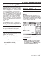
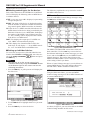
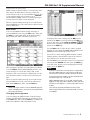
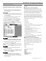
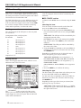
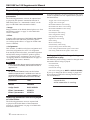
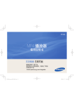
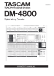
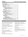
»
DM-3200 Ver1.20 Supplemental Manual
Table of Contents
Summary of additional functions in version 1.20 .................................1
FireWire card support ..............................................................................2
Surround monitor card support ..............................................................2
Naming the mixer ....................................................................................2
Remote operation through MMC ...........................................................3
MIDI control .............................................................................................3
Connection .......................................................................................... 3
Setting devices for MIDI control ........................................................ 3
Selecting devices for MIDI control ..........................................3
Selecting control types for the devices ...................................4
Setting up individual devices ..................................................4
MIDI controllers .................................................................................. 4
MIDI fader ........................................................................................... 4
MIDI mixer ........................................................................................... 5
Changing the assignment ........................................................5
Assigning parameters to rotary encoders..............................................6
Cascade connection .................................................................................6
Cascade connection overview ........................................................... 6
Master/slave setting ........................................................................... 6
Making a cascade connection ............................................................ 7
Settings and Operations that can be interlocked ............................ 7
Settings that can be interlocked .............................................7
Operations that can be interlocked ........................................7
GPI functionality ......................................................................................8
Making connections ........................................................................... 8
Setting the GPI .................................................................................... 8
GPI CONFIG section...................................................................8
TIME EVENT section ..................................................................9
Editing the GPI EVENT LIST ......................................................9
Expanded dynamic automation function ............................................10
Additional dynamic automation parameters ................................. 10
Additional parameters that are re-played as Initial Status ........... 10
Settings prohibited to change during automation re-play ........... 10
Summary of additional functions in version 1.20
FireWire card support
By installing an IF-FW/DM FireWire interface card
(sold separately), it is now possible to transfer audio
data between your computer and a DM-3200. An
IF-FW/DW card can only be installed into Slot 1.
Surround monitor card support
Integrated surround monitoring can be added to the
DM-3200 by installing an IF-SM/DM surround monitor card (sold separately). An IF-SM/DM card can be
installed into either Slot 1 or 2.
Naming the mixer
DM-3200 Ver1.20 allows you to set and edit mixer
names.
Remote operation through MMC
Now you can remotely operate external transports
from a DM-3200 using the MMC (MIDI Machine
Control) protocol.
Change Messages using the new external controllers:
MIDI fader, MIDI controller, and MIDI mixer.
Assigning parameters to rotary encoders
DM-3200 now allows you to assign which parameters
are controlled from the rotary encoders.
Cascade connection
A cascade connection can be made between two
DM-3200 units.
GPI functionality
DM-3200 can now remotely control external devices
using a GPI signal output.
Expanded dynamic automation function
The dynamic automation function of the DM-3200 can
now capture buss assignments, effect parameters, and
image parameters.
MIDI control
External MIDI devices can be controlled from the
DM-3200 using MIDI Control Change and Program
TASCAM DM-3200 Ver 1.20
1
DM-3200 Ver1.20 Supplemental Manual
FireWire card support
By installing an IF-FW/DM FireWire interface card
(sold separately) into Slot 1 of the DM-3200 Ver1.20,
you can transfer audio data between your computer
and the DM-3200. An IF-FW/DM inserted into Slot 2
will not function.
Figure 1 is an example of the panel display when an
IF-FW/DM card is installed in Slot 1.
For more details, please refer to the IF-FW/DM documentation.
Surround monitor card support
By installing an IF-SM/DM surround monitor card
(sold separately), you can add integrated surround
monitoring to the DM-3200.
Figure 1 shows an example of the screen display when
IF-SM/DM card is inserted in Slot 2.
Figure 1: SLOT screen when an IF-FW/DM and an IF-SM/DM
are installed
For more details, please refer to the owner’s manual
that comes with the IF-SM/DM card.
Naming the mixer
DM-3200 Ver1.20 allows you to set and edit mixer
names so that you can easily differentiate between
multiple mixers with the TASCAM Mixer Companion
computer application.
1) On the UTILITY SYSTEM screen, move the cursor to the EDIT button in the MIXER NAME section.
Press the ENTER key.
A popup window will appear for editing the mixer
name.
Figure 2: UTILITY>SYSTEM screen
Note
You can cancel the entered name by pressing
the POD3 key (CANCEL).
Figure 3: Name edit popup screen
2) Enter a name you like.
For more information about the method for entering
names, please refer to “Naming library entries” on
page 32 of the DM-3200 Owner’s Manual.
3) Set the name by pressing the POD2 key (STORE).
The popup window will disappear and the name you
entered will appear in the MIXER NAME section. Figure
4 shows an example of the screen display when the
entered name is “DM-3200.”
2 TASCAM
DM-3200 Ver 1.20
Figure 4: UTILITY>SYSTEM screen when the mixer is
named “DM-3200”
DM-3200 Ver1.20 Supplemental Manual
Remote operation through MMC
DM-3200 Ver1.20 allows you to remotely operate the
transport functions of external devices through MMC
(MIDI Machine Control). Device control is carried out
through the MIDI IN/OUT port. The USB port cannot
be used for this purpose.
Selection of external devices for transport control is
done on the REMOTE/MACHINE CTRL screen. For
details, please see “Selecting devices for transport control” on page 93 of the DM-3200 Owner’s Manual. As
a result of this additional function, the following information is added to “Table 8.3: Supported transport
machine control devices” on page 93. Some devices,
such as the Alesis HD-24, only support a limited range
of functions over MMC, and may not support closed
loop MMC control.
Device
Screen display
Control type
MIDI open loop
MMC Open
M
MMC closed loop
MMC Full
M
Figure 5: Supported transport machine control devices
added in Ver 1.20
The MMC ID is set from the ID field on the Machine
CTRL screen, selectable between 1 and 127 using the
JOG/DATA dial.
These numbers correspond to 0 through 126 in the
MMC protocol, so the controlled device may require
you to set an ID of 0 to match the ‘1’ on the DM-3200,
for example. The all-call ID number, 127 in the MMC
protocol, is not used by the DM-3200.
MIDI control
External MIDI devices can now be operated from a
DM-3200, using MIDI Control Change messages and
MIDI Program Change messages using the MIDI controller, MIDI fader, and MIDI Mixer screens.
Connection
Connect the MIDI IN and MIDI OUT ports of a
DM-3200 and the MIDI device bi-directionally.
You may also use these controllers as “send only”
as well by just connecting the MIDI OUT port of the
DM-3200 to the MIDI device.
Setting devices for MIDI control
Setting of the MIDI control setup is carried out on the
REMOTE>EXT.CTRL screen.
ªSelecting devices for MIDI control
The EXTERNAL CONTROL LIST on the left of the screen
is initially blank. To add external devices from the list
use the following procedure:
1 Turn the POD4 knob or the JOG/DATA dial to choose an
item from the device list (SUPPORTED DEVICES).
In the case of MIDI control, highlight either
MIDI Ctrlrs, MIDI FADERS, or MIDI Mixer.
2 When the device to be controlled by the DM-3200
is highlighted on the list, move the cursor to the
Figure 6: REMOTE>EXT.CTRL screen
ƒADD button, and press the ENTER key. The device
will be added to the EXTERNAL CONTROL LIST on
the left of the screen.
NOTE
To obtain more information regarding a
particular item in the list of devices that may
be controlled by the DM-3200, highlight the
item, move the cursor to the INFO button, and
press the ENTER key. A popup screen provides
information regarding the selected item.
Continued on the next page
TASCAM DM-3200 Ver 1.20
3
DM-3200 Ver1.20 Supplemental Manual
Continued from the previous page
ªSelecting control types for the devices
Each of the columns on the EXTERNAL CONTROL
LIST will display the following when an MIDI device
is added to the list.
STATE: A one-way arrow ® is displayed, representing
an open-loop device.
DEVICE: The name of the device is displayed together
with the number of channels available for transmitting control signals. MIDI control has 16 channels.
ID: If the device is a MIDI controller, ID indicates the
MIDI channel of the device being controlled by the
DM-3200. If the device is a MIDI fader, ID displays
the number of the MIDI Control Change message
(0 - 119). Nothing will be displayed in this column
if the device is a MIDI mixer.
PORT: This displays the output port. For MIDI controls, “MIDI” will automatically display.
CH: This displays the channel number used in the
fader layer. It will display “--” for an MIDI controller, “1-16” for MIDI faders and MIDI mixers.
ªSetting up individual devices
To access the set-up screen of the individual devices
listed in the EXTERNAL CONTROL LIST, move the cursor to the Jump to SCREEN
button and press
the ENTER key.
NOTE
You can also go to the set-up screen of the
individual devices by using the CONTROL button
at the bottom right on the screen and use the
following procedure:
1 Press the POD4 key. A pull-up menu will display the
list of devices.
The following explains the set up screen for each of
the MIDI control devices.
MIDI controllers
You can send MIDI Control Change messages using
the POD knobs of DM-3200.
Figure 8: MIDI CONTROLLERS screen
The MIDI CONTROLLER screen comes with standard controllers. Use the cursor key to move the bordered frame indicating the control messages you want
to use, and use the POD knobs to send MIDI Control
Change messages. This can be done whenever the
MIDI CONTROLLERS screen is displayed regardless
of the setting of the Layer Status.
When a Control Change message is received from an
external MIDI device, the value will be reflected on
the DM-3200’s MIDI CONTROLLERS screen.
MIDI fader
Using the DM-3200 faders, you can send MIDI
Control Change messages to all 16 MIDI channels of
an external MIDI device.
Figure 7: Pull-up screen for switching devices
2 Use the POD4 knob to highlight the device you want
to set.
3 Press the POD4 key to select the device.
Figure 9: MIDI FADERS screen
As shown in figure 9, you can select and set the MIDI
Control Change number on this screen.
Continued on the next page
4 TASCAM
DM-3200 Ver 1.20
DM-3200 Ver1.20 Supplemental Manual
Continued from the previous page
MIDI Volume (Control Change 7) is frequently used.
This allows the DM-3200 to remotely control the
sound volume of up to 16 external MIDI devices. This
is only possible when Layer Status is set to REMOTE
and the MIDI FADER screen is currently showing or
was the last EXT.CTRL screen displayed.
When a Control Change message is received from an
external MIDI device, the value will be reflected in the
fader of DM-3200.
MIDI mixer
You can send MIDI Control Change messages to
external MIDI devices using the POD knobs, fader and
the MUTE key of the DM-3200. In the default setting,
they control pan, fader, and mute respectively.
Figure 11: MIDI>CTRL.CHANGE screen
To display this screen, either press the MIDI key followed by the POD3 key (or keep pressing the MIDI key),
or move the cursor to the Jump to SCREEN
button at the top right on the MIDI MIXER screen,
and press the ENTER key.
Use the POD4 knob to select the key whose assigned
function is to be changed (FADER, PAN or MUTE) in the
TARGET section on the right of the screen.
You will see a chart showing MIDI channel, Control
Change number, and ON/OFF status of the selected
key (channel 1-16) on the left of the screen.
Figure 10: MIDI MIXER screen
This operation is possible only when the Layer Status
is set to REMOTE and the MIDI MIXER screen is currently showing or was the last EXT.CTRL screen
displayed. The screen will show “REM PAN” for the
encoder mode, and the encoders will control the pan
data.
When a Control Change message is received from an
external MIDI device, the value will be reflected in
DM-3200’s POD knobs, fader, and the MUTE key.
NOTE
When the Layer Status is set to REMOTE the pan
value is displayed on, and can be controlled with
the rotary encoders.
Use the cursor key to select the item to be set, select the
value using the JOG/DATA dial, then press the ENTER key
to set the value. When you are changing the ON/OFF
status, press the ENTER key.
NOTE
If there is more than one key that is assigned to
the same MIDI channel, you cannot assign the
same Control Change number to both of them.
A Control Change number can be selected from
the following: 1-5, 7-31, 64-95.
When ON/OFF status is set to ON, a check mark
appears in the check box. When it is OFF, the box
is blank. In the figure 11, all the channels are set
to ON.
You cannot operate the MIDI control of the
channel pan when the surround mode is not set
to STEREO.
Changing the assignment
You can change the MIDI channel, Control Change
number, and ON/OFF status that are assigned to each
of the POD knobs, fader, and the MUTE key. Changes are
made on the MIDI>CTRL.CHANGE screen.
TASCAM DM-3200 Ver 1.20
5
DM-3200 Ver1.20 Supplemental Manual
Assigning parameters to rotary encoders
You can assign parameters to the rotary encoders
using the four encoder mode keys (please refer to
the “Encoders” section on page 20 in the Owner’s
Manual).
In the previous versions of DM-3200, parameters were
pre-assigned as indicated next to each of the encoder
mode keys. In Version 1.20 you can select which
parameter is to be controlled by which of the encoder
mode keys.
assign a parameter from the list in the EDIT TARGET
SELECT section.
Starting at the top, row numbers 1-4 represent the
numbers of the encoder mode keys.
“NONE” means that the encoder key is pressed by
itself, “SHIFT+” means that the encoder key and the
SHIFT key are pressed simultaneously, and “CTRL+”
means that the encoder key is pressed together with the
CTRL key.
For example, if you want to assign a parameter to “the
topmost encoder mode key when it is pressed with
the SHIFT key,” select the field where “Row 1” and
“SHIFT+” cross.
The encoder mode which is currently assigned to the
selected encoder mode key will be highlighted in the
ENCODER MODE SELECT section at the bottom of the
screen.
3 Using the JOG/DATA dial, select the encoder mode to
be assigned to the highlighted encoder mode key,
from the ENCODER MODE SELECT section.
NOTE
Figure 12: OPTION>ENCODER MODE scree
Parameters are assigned on the ENCODER MODE
screen, which is a sub-screen newly added to the
OPTION screen.
1 Press the OPTION key to display the OPTION screen,
then use the POD4 knob (or press the OPTION key
again) to display the ENCODER MODE subscreen.
2 Use the cursor key to select the encoder mode key to
Depending on whether the surround mode is
set to STEREO or not, the options given in the
ENCODER MODE SELECT section differ.
4 Press the ENTER key.
Assignment of the parameter is now complete and will
be displayed in the EDIT TARGET SELECT section.
NOTE
You need to perform the corresponding encoder
mode key operation in order to assign the set
parameter to a rotary encoder.
Cascade connection
DM-3200 Ver1.20 allows you to make a cascade connection between two DM-3200 units.
Cascade connection overview
Two DM-3200 units that are connected by a cascade
connection can be operated as though they are one
mixer.
• STEREO buss, BUSS 1-16, AUX buss 1-8, and
SOLO buss can be shared when the sharing function is set to ON in the CASCADE screen.
• The audio clock is shared by the two units.
• Timecode is shared to synchronize the two units.
• Various settings and operations can be interlocked
between the two units. Please refer to the “Settings
and Operations that can be interlocked” section on
page 7 of this supplement.
6 TASCAM
DM-3200 Ver 1.20
Master/slave setting
You need to set one DM-3200 to be the cascade master and the other to be the cascade slave. Any set-up
that affects the operation of the system as a whole will
be performed on the cascade master.
• An audio clock source is selected from the clocks
fed to the cascade master. You cannot select the audio clock source on the cascade slave.
• Timecode fed to the cascade slave cannot be used
as the synchronization source.
• The cascade connection can be turned ON and OFF
only on the cascade master.
• When the cascade connection is ON, the parameter
set-ups on the cascade master (parameters to be
interlocked) are reflected on the cascade slave.
Continued on the next page
DM-3200 Ver1.20 Supplemental Manual
Continued from the previous page
Making a cascade connection
This section explains how to make a cascade connection between two DM-3200s that are running Version
1.20.
1 Using the TASCAM cascade cable (PW-1000CS –
sold separately), connect the CASCADE ports of
the two DM-3200.
WARNING
Only use the special TASCAM cascade cable. Use
of any other type of cable may result in damage
to the equipment.
2 Set one of the DM-3200 units to be the cascade
master, and the other the cascade slave.
To set the master and slave, display the DIGITAL
screen using the DIGITAL key in the SCREEN MODE/
NUMERIC ENTRY section, and use the POD3 key
(or continue pressing the DIGITAL key) to display the
CASCADE sub-screen. Set the ID of one of the units
to MASTER, and the other to SLAVE.
Figure 13: DIGITAL>CASCADE screen
NOTE
Set the unit ID while the ON/OFF set-up is OFF.
You cannot change the ID set-up while it is ON.
3 Turn the ON/OFF setting on the CASCADE subscreen of the cascade master to ON.
Move the cursor to the ON/OFF button and press the
ENTER key. A confirmation screen will come up. Check
the setting and press the ENTER key again to confirm.
NOTE
ON/OFF status cannot be changed while the
timecode is running.
4 When a cascade connection is established, a pop-up
message “Cascade connection established” will be
displayed. Press the ENTER key.
NOTE
If a cascade connection was not properly
established, a pop-up message “Cascade Slave
not found. Cascade connection not established”
will be displayed.
Settings and Operations that can be interlocked
ªSettings that can be interlocked
The following settings are interlocked between the
two DM-3200 units while there is a cascade connection between them.The initial settings on the cascade
master will be reflected on the cascade slave immediately after a cascade connection is established.
After the cascade connection has been made, whenever a setting is changed either on the cascade master or the cascade slave, the changed setting will be
reflected on the setting of the other unit. However, the
ON/OFF setting of the cascade connection can only be
changed on the cascade master.
Layer status
Flip mode
Encoder mode
Surround mode
Surround 5.1 rear MONO
DIGITAL>CASCADE screen setup (except for ID setting)
OPTION>SETUP screen setup (except for FADER
SENSITIVITY)
OPTION>PREFERENCE screen setup
OPTION>SOLO screen setup (except for INPLACE
SOLO DEFEAT setup)
OPTION>ENCODER MODE screen setup
METER/FADER>METER screen setup
SNAPSHOT RECALL SAFE setup on the LIBRARY
SNAPSHOT screen
AUTO SETUP screen setup
Key setup in the AUTOMATION section (WRITE, TRIM,
ALL SAFE, REHEARSE, INITIAL EDIT)
ªOperations that can be interlocked
The following operations are interlocked while there
is an established cascade connection between two
DM-3200 units. Whenever any of the below operations is executed either on the cascade master or the
cascade slave, the other will follow with the exact
same operation.
Snapshot related operations:
Recall
Store
Delete
Automation key operations:
TOUCH key
KEEP key
REVERT key
INITIAL EDIT DISCARD key
AUTO FADE key
TASCAM DM-3200 Ver 1.20
7
DM-3200 Ver1.20 Supplemental Manual
GPI functionality
DM-3200 Ver1.20 supports GPI functionality. This
allows you to send 8 output signals from the GPI port
(D sub 9-pin connector) on the rear panel, and control
external devices from the DM-3200.
The right side of the screen allows you to set which
event is to happen when the GPI is controlled by the
timecode.
The DM-3200 allows you to give different trigger settings to each of the GPI ports for GPI signal output.
You can choose the trigger source from a fader, MUTE
key control, transport control, machine control key
status and its operation, or a timecode value.
Columns on the SETUP list are selected using the cursor
key.
Making connections
The specifications of the GPI ports on the rear panel
are as follows:
Arrangement of the serial port pins:
Pin number
#1
#2
#3
#4
#5
#6
#7
#8
#9
Function
GPI output port 1
GPI output port 2
GPI output port 3
GPI output port 4
GND
GPI output port 5
GPI output port 6
GPI output port 7
GPI output port 8
Output level: 5V
Setting the GPI
GPI is set using the GPI sub-screen, which is a new
addition to the UTILITY screen.
ªGPI CONFIG section
Selecting the item
You can set the item that controls each of the GPI
ports in the ITEM column of the SETUP list.
1 Pre-select the item type from the ITEM SELECT section at the bottom left of the screen, using the POD1
knob.
TIME EVENT: The GPI port will be controlled by the
designated timecode value.
KEY EVENT: The status of the transport key, F1-F12
key, and the status of the MUTE key will control the
GPI port.
FADER EVENT: The GPI port will be controlled by
the status of the fader.
2 Using the cursor key, highlight a cell in the ITEM column that you wish to set, and select the item using
the JOG/DATA dial.
Depending on which item type is selected in step 1
above, the options given vary as follows:
TIME EVENT: TIME EVENT or no assignment (------)
KEY EVENT: REW, FF, STOP, PLAY, REC, F1-F1, MUTE
(CH1-48, BUSS1-16, AUX1-8), or no assignment (------)
FADER EVENT: FADER
(CH1-48, BUSS1-16, AUX1-8, STEREO) or no assignment
(------)
3 Press the ENTER key to confirm the setting.
Selecting the type
The Waveform to be output from each of the ports can
be set in the TYPE column in the SETUP list.
Use the cursor key to highlight a cell in the TYPE column that you want to edit, and select the item using
the JOG/DATA dial.
Depending on the type of the item you selected, the
options given vary as follows:
Figure 14: UTILITY>GPI screen
TIME EVENT: TYPE column will show “------” and the
setting of the type is done in the GPI EVENT LIST on
the right of the screen.
The GPI CONFIG section on the left of the screen
allows you to set the item and the type of the GPI
output trigger for each of the ports and the ON/OFF
status of the GPI function.
Continued on the next page
8 TASCAM
DM-3200 Ver 1.20
DM-3200 Ver1.20 Supplemental Manual
Continued from the previous page
FADER EVENT
: output low pulse when the fader starts
: output high pulse when the fader starts
: output low pulse when the fader stops
: output high pulse when the fader stops
: output low pulse when the fader starts or stops
: output high pulse when the fader starts or stops
: output changes to low level when the fader
starts, and to high level when the fader stops
: output changes to high level when the fader
starts, and to low level when the fader stops
NOTE
”When the fader starts” means when the fader
level is brought up from the lowest level.
”When the fader stops” means when the fader
level is brought down to the lowest level.
The Output pulse range is approximately 150ms.
KEY EVENT
: output low pulse when the key status changes
: output high pulse when the key status changes
Selecting the port
GPI ports can be selected in the PORT column on the
GPI EVENT LIST. You can only select a port whose
item has been set to be a TIME EVENT in the GPI CONFIG
section. Use either the cursor key or the POD4 knob to
highlight a cell in the PORT column that you want to
edit, use the JOG/DATA dial to select the port, then press
the ENTER key to confirm the selection. You can select
the same port for more than one time event.
Setting the time
You can set the time when an event is to be executed.
Use either the cursor key or the POD4 knob to highlight
a cell in the TIME column that you wish to set, use the
JOG/DATA dial to set the time, then press the ENTER key
to confirm.
Setting the type
You can set the output waveform type for each of the
GPI ports.
Use either the cursor key or the POD4 knob to highlight
a cell in the TYPE column that you want to edit, then
use the JOG/DATA dial to select the type.
: output low pulse at the designated time
: change to low level when the key status is turned
on, and to high level when the key status is turned off
: output high pulse at the designated time
: change to low level at the designated time
: change to high level when the key status is
turned on, and to low level when the key status is turned off
NOTE
The output pulse range is approximately 150ms.
Options for F5-F8 are either low pulse output or
high pulse output.
ON/OFF setting
Set this to ON when you want to activate each of the
GPI ports.
When the TYPE is set to TIME EVENT, it will always
display OFF and the ON/OFF setting will be governed
by the setting in the GPI EVENT LIST on the right of the
screen.
ªTIME EVENT section
You can set up to 16 time events in the GPI EVENT
LIST.
How to control the GPI EVENT LIST
• To move the cursor vertically within the list, use
either the up and down cursor key or the POD4 knob.
• To move the cursor horizontally (across the columns), use either the right and left cursor key.
• Arrows at the top and the bottom of the right-hand
side of the list mean that there are more time events
outside of the screen. To scroll the list vertically,
use the POD4 knob. You cannot use the up and down
cursor key to scroll the list.
: change to high level at the designated time
ON/OFF setting
Set this to ON when you want to activate the settings
of individual GPI ports.
ªEditing the GPI EVENT LIST
You can edit the GPI EVENT LIST by highlighting the
button at the bottom right on the screen and then by
pressing the ENTER key.
SORT PORT: This sorts the GPI EVENT LIST by port
numbers.
SORT TIME: This sorts the GPI EVENT LIST by time.
CAPTURE TC: This sets the TIME of the highlighted
time event to the current timecode value.
DELETE: This deletes the highlighted time event.
NOTE
You can scroll within the GPI EVENT LIST while
the cursor is pointing at CAPTURE TC or DELETE
using the JOG/DATA dial. The JOG/DATA dial icon
at the upper right corner of the list will become
black.
TASCAM DM-3200 Ver 1.20
9
DM-3200 Ver1.20 Supplemental Manual
Expanded dynamic automation function
Additional dynamic automation
parameters
The following parameters can now be captured and
re-played by the dynamic automation function of
DM-3200 (please see “Automated Controls” on the
page 4 of the DM-3200 Automation Guide).
• Image
Image parameter of the linked channel (please see “Pan
and balance settings” on page 71 of the DM-3200
Owner’s Manual).
• Effect
Common effect parameters (TYPE, INPUT, MIX, BYPASS,
OUTPUT) and TASCAM effect parameters (please
see “Setting up the effects” on page 82 of DM-3200
Owner’s Manual).
• Assignments
This includes, in addition to the buss assignment and
stereo buss assignment, the AUX 1-2 assignment
from the BUSS and stereo buss, surround assignment
and ON/OFF setting of CSP/LFE speakers (please
see “Channel-to-buss assignment” on page 51 and
“Assigning channels to surround busses” on page 75
of the DM-3200 Owner’s Manual).
NOTE
When any of the above mentioned parameters
is a continuous variable, the Revert function is
applied to it.
NOTE
On the AUTO CONFIG screen, each of these
additional parameters is related to an item as
shown below (please see “AUTO CONGIG” on
page 14 of the DM-3200 Automation Guide).
parameter
item
IMAGE
PAN/BAL
Assign Swtch
BUSS ASSIGN
Effect 1 parameters
EFFECT 1
Effect 2 parameters
EFFECT2
With these additions, all of the parameters that can be
stored as snapshots are now captured and re-played as
the Initial Status.
Trigger source of the compressor
Trigger source of the gate
ROUTING>INPUT screen setting
ROUTING>OUTPUT screen setting
ROUTING>INSERT screen setting
Pan mode setting
Surround pan mode setting
Direct assignments setting
Pan gang button setting
Digital trim value setting
Phase setting
Mono switch setting
Channel delay value setting
Pre/post setting of the channel delay
Level setting of BUSS/AUX signal to stereo buss
Pan setting of BUSS/AUX signal to stereo buss
Settings prohibited to change during
automation re-play
The following mixer settings cannot be changed while
automation data is being re-played.
Surround mode
Grouping setting
Channel link setting
Pan switch setting [Set by SHIFT + OUTPUT ASSIGN]
If you try to change the above settings, a popup window will appear with below message and the operation will be denied.
cannot do this
while automation is running.
Additional parameters that are re-played
as Initial Status
The following parameters are now captured and
re-played as the Initial Status of the automation
(please see “Initial Status” on page 32 of DM-3200
Automation Guide).
10 TASCAM
DM-3200 Ver 1.20
Memo
TASCAM DM-3200 Ver 1.20
11
TEAC CORPORATION
Phone: +81-422-52-5082
D00908410A
3-7-3, Nakacho, Musashino-shi, Tokyo, 180-8550 Japan
Printed in China