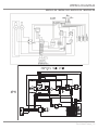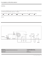
1
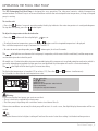
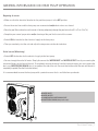
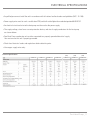
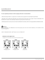
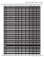
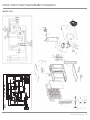
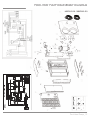
OWNER’S MANUAL
POOL HEAT PUMP
30HPRA-E-410
50HPRA-E-410
50HPRA-E-410 (3PH)
80 HPRA-E-410
80HPRA-E-410 (3PH)
100 HPRA-E-410
100HPRA-E-410 (3PH)
MDPL-00002B-V1-E
43, de l’Alcazar - Blainville, Québec - Canada - J7B 1R4
www.dplpool.com
CAUTION
Shipping Damage MUST be reported to the Carrier IMMEDIATELY!!! Examine the exterior. Remove cover and examine
compressor and piping for signs of damage.
Warning:
Prior to starting the heat pump, you must ensure that:
> Electricity is supplied to the heat pump.
> The filter pump is operating with a minimum water circulation of 5.1 m3/h with a maximum pressure of 3 BARS.
If these two conditions are not met, the heat pump with not start. In such case, the digital display thermometer
will be unusable.
Pool Heat Pump _1
TABLE OF CONTENTS
_Introduction
3
_DPL Pool Heat Pump Features
4
_Safety Precautions
5
_Operating the Pool Heat Pump
6
_General Information On Heat Pump Operation
> Beginning of season
> End of season (winterizing)
7
7
7
_Pool Heat Pump Installation
> Determining optimum location
> Clearance
> Level placement
> Securing the unit
> Condensation and drainage
> Water flow
> Electrical connections
8
8
8
8
9
9
10
10
_Electrical Specifications
11
_Connecting Electrical Conductors
12
_Wiring Diagram
13
_Plumbing Specifications
> Installation
> Check valve & chemical trap loop
> Flow rate
> External bypass
14
14
14
15
15
_Maintenance
16
_Replacement Parts Guide
17
_Pool Heat Pump Disassembly Diagram
18_19
_Troubleshooting
20_21
_Temperature Controller Programming
22
_Product Warranty
23
_Notes
24
Pool Heat Pump _2
INTRODUCTION
Dear Valued Customer,
Thank you for purchasing this DPL product.
We hope that you will derive as much pleasure from using this product as we did in manufacturing it. In order to bring you
the best possible products, we want to know your comments about the product. You can e-mail us at [email protected]
or contact customer service at +1.450.818.4758
For easy reference, we suggest that you attach a copy of your sales slip/receipt to this page, along with the following
information which can be found on the manufacturer’s nameplate located on the side of the unit.
Model number:
Serial number:
Date of purchase:
Date of installation:
Dealer’s Name and Address:
You will be asked this information if your unit requires servicing and/or for general inquiries.
Pool Heat Pump _3
DPL POOL HEAT PUMP FEATURES
> Digital display thermostat.
> ROTARY or SCROLL energy-efficient compressor.
> Aluminium/copper evaporator with one or two vertically-positioned ventilator(s). This configuration
greatly reduces noise output while improving heat exchange efficiency.
> Titanium double coil, according to model. Titanium heat exchangers are very resistant
to all chemical imbalances.
> The cabinet of all our product are with vacuum plastic, and with Aluminium.
> Stainless steel screws with nylon washers and painted steel grill.
> Access holes for service gauges.
> Superior quality thermostatic expansion valve, distributor and filter.
> Safety approval by CE.
> Each Pool Heat Pump is factory run tested.
Specifications
Model
30HPRA-E-410
50HPRA-E-410
80HPRA-E-410
(3 PH)
(3 PH)
(3 PH)
100HPRA-E-410
50HPRA-E-410
80HPRA-E-410
100HPRA-E-410
Digital display
Digital display
Features
Temperature control
Adjustable thermostat (°C and °F)
Heat exchanger
Digital display
Digital display
Digital display
16~35 °C (60-95 °F)
16~35 °C (60-95 °F)
16~35 °C (60-95 °F)
16~35 °C (60-95 °F) 16~35 °C (60-95 °F)
Digital display
Digital display
16~35 °C (60-95 °F)
16~35 °C (60-95 °F)
Titanium
Titanium
Titanium
Titanium
itanium
Titanium
Titanium
Double coil
Double coil
Double coil
Double coil
Double coil
Double coil
Double coil
R410A
R410A
R410A
R410A
R410A
R410A
R410A
1.65
2.0
2.65
3.2
2.0
2.65
3.2
Automatic restart function after power failure
Yes
Yes
Yes
Yes
Yes
Yes
Yes
Compatible with salt chlorination systems
Yes
Yes
Yes
Yes
Yes
Yes
Yes
Automatic defrost operation
Yes
Yes
Yes
Yes
Yes
Yes
Yes
Heat exchanger special feature
Refrigerant type
Refrigerant charge
kg
Galvanized steel cabinet
Compressor type
Thermostatic expansion valve
Yes
Yes
Yes
Yes
Yes
Yes
Yes
Rotary
Rotary
Scroll
Scroll
Rotary
Scroll
Scroll
Included
Included
Included
Included
Included
Included
Included
26.5
Performance ratings
Power restored *
kw
10.5
14
21
26.5
14
21
Power consumed *
kw
2.17
2.65
4.7
6.3
2.65
4.7
6.3
4.9
5.3
4.5
4.2
5.3
4.5
4.2
COP (Power restored / Power consumed) *
Acoustic power
dB(A)
52
55
59
61
55
59
61
Water flow rate
m3/h
Minimum
5.1
5.1
8.2
8.2
5.1
8.2
8.2
Maximum
15
15
15
15
15
15
15
mm
Width
1140
1255
1255
1255
1255
1255
1255
Height
890
930
1135
1135
930
1135
1135
Depth
385
415
415
415
415
415
415
77
88
128
128
88
128
128
1160
1275
1275
1275
1275
1275
1275
Dimensions & Weight
Unit
Carton
Dimensions
Weight
Kg
Net
Dimensions
mm
Width
Weight
Kg
Height
920
960
1360
1360
960
1360
1360
Depth
450
480
480
480
480
480
480
Shipping
85
95
138
138
95
138
138
All technical data subject to change without notice.
Pool Heat Pump _4
SAFETY PRECAUTIONS
This manual is a guide to the proper installation of the DPL Pool Heat Pump. Improper installation may result in unsafe
and dangerous conditions that will void the factory warranty. Prior to installation, read these instructions and any instructions that are packaged with separate pieces of equipment that make up the system. Please read these instructions thoroughly and carefully before attempting installation or operation. Failure to follow these instructions may result in improper
installation, operation, service, or maintenance, possibly resulting in fire, electrical shock, property damage, personal
injury, or death.
General Precautions:
> Ensure proper supervision of unit in the presence of children or persons unfamiliar with
pump operation.
> Do not hang or lay clothes or other objects on the unit.
> Keep the evaporator coil clean. Any restrictions to the air flow of the evaporator coil can seriously affect
system performance.
> This device must be installed in compliance with national electrical standards.
> Do not insert foreign objects between the air flow swivelling blades as this may damage the
ventilator or cause injury.
> The unit must never be placed on its side or upside down, as the compressor oil will run into
the cooling circuit and seriously damage the unit.
> Please be advised that attempting to repair this unit by yourself is done at your own risk. It is
recommended to contact the store of purchase or an authorized service centre.
Caution:
The manufacturer disclaims all liability for any accident, during the installation or use of this product, as a result of the
unsafe installation of the heat pump. If you encounter difficulties during installation, please contact the store of purchase
or an authorized service centre.
Caution:
This device is not intended for use by persons with reduced physical, sensory or mental capacities (including children),
or lack of experience and knowledge, unless they are supervised by an adult or have been given instruction concerning
the use of the device. Children should be supervised to ensure that they do not play with the device.
Pool Heat Pump _5
OPERATING THE POOL HEAT PUMP
The DPL Swimming Pool Heat Pump is designed for easy operation. The side panel contains a digital temperature
control readout. The Heat Pump is set to reach and then maintain the selected pool water temperature, as long as the pool
pump is running.
To start the unit:
> Press the
button. In normal operating mode, the display indicates the water temperature in centigrade degrees.
To stop the heat pump, press the
button again.
To adjust the temperature to the desired value:
> Press the
button until the red pilot light
turns on.
> To adjust the water temperature, press the
or
buttons until the targeted temperature is displayed.
The available temperature range is between 18 °C and 35 °C.
> To return to normal operating mode, press the
button again, for at least 5 seconds.
The
pilot light turns on whenever the heat pump is in operation, which means that the ventilator(s) and the compressor
are functioning in order to heat the pool.
All models use a 5-minute time delay to prevent repeated tripping of the compressor's overload protection mechanism, which is
caused by attempting startup before system pressures are equalized. Any interruption will result in a 5-minute time delay.
The
pilot light will blink during this 5-minute time delay.
To display the temperature in farenheit (°F) or celcius (°C), Press the
for 3 seconds to select the desired temperature scale.
E
A
B
F
C
D
and
buttons simultaneously
A:
pilot light
B:
pilot light
C: Digital display
D: Button to set temperature at desired value
E: Start/stop button
F: Temperature adjustment buttons
Warning:
Prior to starting the heat pump, you must ensure that:
> There is electricity supplied to the heat pump.
> The filter pump is operating with a minimum water circulation of 6 m3/h.
If these two conditions are not met, the heat pump will not start. In such a case, the digital display thermometer will be unusable.
TIP:
Setting the thermostat to its highest setting will not heat the water faster than setting it at the desired temperature.
Pool Heat Pump _6
GENERAL INFORMATION ON HEAT PUMP OPERATION
Beginning of season:
> Make sure that the electrical breaker for the pool heat pump is in the OFF position.
> Ensure the water lines and the heat pump are reconnected and/or drain valves are closed.
> Clean the pool filter and make sure the water is flowing adequately through the pool return line (5.1 m3/h to 15 m3/h).
> Complete your normal preparation and/or cleaning of the pool for the start of the season.
> Switch ON the breaker for the electrical supply to the heat pump.
> Then you need only start the unit and adjust the temperature to the desired value.
End of season (Winterizing)
> Switch OFF the breaker for the electrical supply to the heat pump.
> You must empty the unit of all water. Simply disconnect the WATER INLET and WATER OUTLET lines by unscrewing the
two union fittings on the front of the unit. To completely remove the water from the heat exchanger, you must remove the
drain cap (WINTERIZING DRAIN) that is located on the side of the unit. You must then let the water flow out until the unit is
completely emptied. (See the illustration below.)
It is recommended to cover the heat pump with a protective cover that is available from your dealer.
A: WATER INLET
B: WATER OUTLET
C: CONDENSATION WATER DRAIN PIPE
D: WINTERIZING DRAIN (with plastic caps)
B
A
D
C
Pool Heat Pump _7
POOL HEAT PUMP INSTALLATION
Determining Optimum Location
Choose a location where the noise of the heat pump, when running, and the discharged air will not disturb the neighbours.
Install the Pool Heat Pump unit on a flat, stable surface that can support its weight and does not generate any unnecessary
noise and vibration.
Clearance
Choosing the location of your heat pump is very important. You should install it as close as possible to the filter system.
You should obey the clearance distances around the heat pump that are given in the drawing below.
Level Placement
We recommend that you install your heat pump on a solid base, for example two concrete tiles. Four (4) rubber pads (absorbent pads) are provided to lessen the transfer of vibrations. (See drawing below.)
60 cm (24 in) or more
(Top)
(Front)
30 cm (12 in) or more
30 cm (12 in) or more
(Side)
A
(Front)
(Side)
60 cm (24 in) or more
A
40 cm (16 in) or more
A: Concrete tile
Pool Heat Pump _8
POOL HEAT PUMP INSTALLATION
Securing the unit
We recommend that you secure the unit to the concrete pad by using four (4) TAPCON screws and washers.
(See drawing below.)
A: Concrete Pad
B: 1/4” x 1-1/2” Stainless Steel Concrete Screw
and Washer (Provided by installer)
C: 3/16” Drilled Hole
B
C
3” minimum
A
Condensation and Drainage
The evaporator coil will produce condensation while the unit is running and drain at a steady rate, usually 11 to 19 liters,
depending on the ambient air temperature and humidity.
It is normal for condensation to drip out the CONDENSATION WATER DRAIN PIPE that is located on the side of the unit.
(See drawing below.)
A
A: CONDENSATION WATER DRAIN PIPE
B: WINTERIZING DRAIN (with plastic caps)
B
Pool Heat Pump _9
POOL HEAT PUMP INSTALLATION
Water flow
To minimize heating time, make sure all water valves are open completely, that the water level of the pool is at the
correct height. DPL Pool Heat Pump is designed to operate at full flow through the heat exchanger (condenser). A flow
rate of 6 m3/h to 15 m3/h should be maintained.
Caution:
Either no flow or a low flow rate will cause the unit to shut down. The Pool Heat Pump will not operate without a flow of water.
Electrical connections
This includes the heat pump, swimming pool metal panels, light, heat pump, filter, chlorine generator, as well as any other
metal component or electrical equipment.
Some older swimming pools might not have an electrical connector cable. In such cases, you must drive
a 0.9 to 1.2 meters copper rod into the ground next to the equipment.
The ground connector of the DPL heat pump is located on the side of the unit.
(See drawing below.)
Warning:
Your warranty may be voided if the equipment is improperly connected.
A: Ground connector
Pool Heat Pump _10
ELECTRICAL SPECIFICATIONS
> A qualified person must install the unit in accordance with all national and local codes and guidelines (NFC - 15 - 100).
> Power supply wires must be such a certification YZW, and shall not be lighter than code designation 60245 IEC 57.
> An electrical circuit exclusive to the heat pump must be used as the power supply.
> The supply voltage, size of over-current protective device, and size of supply conductors for the heat pump
are shown below.
> Pool Heat Pump condensing unit must be connected to a properly grounded electrical supply.
You must ensure this unit is properly grounded.
> Check local electrical codes and regulations before obtaining wire.
> Use copper supply wires only.
Electrical Specifications
30HPRA-E-410
50HPRA-E-410
80HPRA-E-410
100HPRA-E-410
(3 PH)
(3 PH)
(3 PH)
50HPRA-E-410
80HPRA-E-410
100HPRA-E-410
Pool Heat Pump _11
CONNECTING ELECTRICAL CONDUCTORS
You must remove the electrical connection box cover to access the electrical compartment. Wiring connections must be
made exactly as shown in the wiring diagram found under the top cover inside the Pool Heat Pump.
A disconnect switch must be installed near the outdoor unit for easy disconnection of power to the Pool Heat Pump.
C
E
D
A
B
A: Disconnect switch
B: Electrical conductor
C: Electrical connection box cover
D: Terminal block
E: Terminal block (3 PH]
CAUTION
Operating the unit with improper line voltages constitutes abuse and will affect unit reliability and operation. Do not install
a system where voltage or phase imbalances may occur above or below permissible limits.
WARNING
Disengage main power disconnect before attempting installation
Pool Heat Pump _12
WIRING DIAGRAM
30HPRA-E-410 - 50HPRA-E-410 - 80HPRA-E-410 - 100HPRA-E-410
3PH
Pool Heat Pump _13
PLUMBING SPECIFICATION
Installation
The typical plumbing diagram illustrates the standard plumbing layout with a single heat pump unit. Following the diagram
from left to right, the plumbing sequence is as follows:
Pool
Pool Pump
Filter
Heat Pump
Check Valve
Chemical Loop
Chlorinator
Pool
A detachable connection (union) must be utilized immediately adjacent to heater to facilitate servicing and winterizing of
the unit.
A: Chlorinator
B: Chemical Loop or Optional Chlorine Generation System
C: Check Valve
D: Pool Heater
E: E: 3 Manual Bypass Valve
(Recommended installation)
F: Filter
G: Pool Pump
Pool Heat Pump _14
PLUMBING SPECIFICATIONS
B
C
A
A: WATER INLET
B: WATER OUTLET
C: DETACHABLE CONNECTION (union) included
C
Factory connections are for a 1 1/2" union nut.
Join the Pool Heat Pump inlet and outlet with rigid PVC (schedule 40). All joints must be glued with PVC glue. If rigid pipe
is not available, you can use soft or flexible piping with stainless steel clamps.
When the piping installation is completed, start the pool pump and check the system for leaks.
Check valve & Chemical trap loop
Ensure that the check valve and chemical trap loop are installed as shown above. The loop should be at least 200 mm
above the top of the chlorinator/feeder to prevent chlorine backup into the heater when the water pump is off. Install a
check-valve on the heater side of the loop to prevent chlorine damage.
Flow rate
The DPL Pool Heat Pump is designed to handle the full flow from the pool pump. No bypass is required if the flow is in the
6 m3/h to 15 m3/h range.
Warning:
Flow rates exceeding 15 m3/h may damage the unit and compromise its efficiency.
External Bypass
Good practice also suggests considering the use of an external bypass on the inlet and outlet to enable the pool owner
to bypass the pool heater if service or maintenance is required.
Pool Heat Pump _15
MAINTENANCE
To ensure optimum performance of the heat pump, follow these recommendations:
> Backwash the pool filter on a regular basis in order to ensure proper flow rate through the pool heater.
> Keep the surfaces of the coil (evaporator) clean and free of any obstruction such as papers, leaves or other debris. The
aluminium fins can be easily and safely cleaned using a low pressure water spray.
> Carefully clean the unit using a soft, non-abrasive and bleach-free cleaner, and rinse using a garden hose without the nozzle.
Warning:
Before performing any maintenance on the heat pump you must turn off the electricity at the breaker of the
electrical supply line.
RECOMMENDED BYPASS ADJUSTMENT
Adjustment of the bypass valves
;OLHKQ\Z[TLU[TH`]HY`HJJVYKPUN[V[OLWVVSW\TWZPaLHUK[OLJSPTH[PJJVUKP[PVUZ
HEATER
T
HEATER
T
IN
IN
IN
OUT
OPEN
HEAT
TER
OUT
OPEN
OUT
CLOSED
Cold Water
Warm Water
Hot Water
Approximately 60% of the water
is circulating in the unit.
Approximately 80% of the water
is circulating in the unit.
100% of the water
is circulating in the unit.
Pool Heat Pump _16
REPLACEMENT PARTS GUIDE
(3PH)
(3PH)
(3PH)
50HPRA-R410
80HPRA-R410
100HPRA-R410
P20001
P20001
P20001
P20001
P20016
P20003
P20016
P20016
P20004
P20004
P20004
P20004
P20004
P20002
P20017
P20017
P20002
P20017
P20017
1
P20006
P20018
P20018
P20006
P20018
P20018
Back panel
1
P20005
P20019
P20019
P20005
P20019
P20019
7
Grid
1 or 2
P20007
P20007
P20007
P20007
P20007
P20007
8
Foot
4 or 6
P20008
P20008
P20008
P20008
P20008
P20008
Part No.
Description
Qty
1
Bottom panel
1
P20001
P20001
2
Left panel
1
P20003
P20016
3
Top panel
1
P20004
4
Right panel
1
5
Front panel
6
50HPRA-R410
80HPRA-R410
100HPRA-R410
9
Power cover
1
P20020
P20020
P20020
P20020
P20020
P20020
10
Evaporator
1
P30045
P30046
P30046
P30045
P30046
P30046
11
Low pressure gauge
1
P30019
P30019
P30019
P30019
P30019
P30019
12
High pressure gauge
1
P30018
P30018
P30018
P30018
P30018
P30018
P30020
13
Electrical compartment
1
P30020
P30020
P30020
P30020
P30020
14
Aluminum frame
1
P30021
P30022
P30022
P30061
P30022
P30022
15
Liquid tight connector
2
P30081
P30081
P30081
P30081
P30081
P30081
Flexible cable duct
16
1
P30082
P30083
P30083
P30082
P30083
P30083
17
Digital thermostat with defrost option
1
P30142
P30142
P30142
P30142
P30142
P30142
18
Side panel (digital thermostat)
1
P10118
P10118
P10118
P10118
P10118
P10118
19
Door (Digital thermostat)
1
P10117
P10117
P10117
P10117
P10117
P10117
20
Screws (Digital thermostat)
2
P30047
P30047
P30047
P30047
P30047
P30047
21
Compressor
1
P30031
P30032
P30033
P30062
P30063
P30064
1
P30036
P30037
P30037
P30036
P30037
P30037
22
23
Thermostatic expansion valve
Filter - dry bi-flow
1
P30149
P30149
P30149
P30149
P30149
P30149
24
Electric conection box
1
P30076
P30076
P30076
P30076
P30076
P30076
25
Electric connector
1
P30050
P30050
P30050
P30050
P30050
P30050
26
Insulation
1
P30034
P30035
P30035
P30034
P30035
P30035
27
Coil temperature sensor
1
P30103
P30103
P30103
P30103
P30103
P30103
28
Water temperature sensor
1
P30099
P30026
P30026
P30099
P30026
P30026
29
Copper pipe (Sensor)
1
P30025
P30025
P30025
P30025
P30025
P30025
30
Titanium well
1
P30024
P30024
P30024
P30024
P30024
P30024
31
Heat exchanger
1
P30008
P30008
P30008
P30008
P30008
P30008
1
P30012
P30012
P30012
P30012
P30012
P30012
32
Heat pump heat exchanger drain
33
Motor(s) bracket
1
P30009
P30010
P30010
P30009
P30010
P30010
34
Motor (s)
1 or 2
P30028
P30028
P30028
P30028
P30028
P30028
35
Fan(s)
1 or 2
P30027
P30027
P30027
P30027
P30027
P30027
1 or 2
P30065
P30065
P30065
P30065
P30065
P30065
1
P30049
P30049
P30049
P30066
P30066
P30066
P30061
P30061
P30061
P30061
P30054
36
37
Capacitor (Fan motor)
Contactor
38
Four way valve and Cran casing heating relay
2
P30061
P30061
39
Running capacitor
1
P30056
P30057
P30057
1
P30065
P30065
P30065
40
41
Capacitor clip
Transformer 208-230V / 24V
1
P30054
P30054
P30054
P30054
P30054
42
Fan motor relay
1
P30065
P30065
P30065
P30065
P30065
P30065
43
Electric box
1
P30058
P30058
P30058
P30058
P30058
P30058
Terminal block
1
P30052
P30052
P30052
P30052
P30052
P30052
1
P30051
P30051
P30051
P30051
P30051
P30051
44
45
Water pressure switch
46
Distributor
1
P30039
P30040
P30041
P30039
P30040
P30041
47
Low pressure switch
1
P30043
P30043
P30043
P30043
P30043
P30043
48
High pressure switch
1
P30044
P30044
P30044
P30044
P30044
P30044
49
50
Terminal block (Main)
1
P30075
P30075
P30075
P30067
P30067
P30067
51
Reversing valve
1
P30149
P30148
P30148
P30149
P30148
P30148
52
Rotalock connector (part #1 copper)
1
P30131
P30131
P30131
P30131
P30131
P30131
53
Rotalock connector (part #2 teflon ring)
1
P30132
P30132
P30132
P30132
P30132
P30132
54
Rotalock connector (part #3 titanium)
1
P30133
P30133
P30133
P30133
P30133
P30133
55
Condensing drain bracket
1
P30073
P30073
P30073
P30073
P30073
P30073
56
Heat exchanger drain bracket
1
P30073
P30073
P30073
P30073
P30073
P30073
57
Refrigerant acces valve bracket
1
P30078
P30078
P30078
P30078
P30078
P30078
1
P30023
P30023
P30023
P30023
P30023
P30023
58
Drain pipe cap
59
60
Heat pump pool heater _17
47
51
54
46
50
53
2
3PH
57
52
48
9
6
10
8
11
1
12
3
33
13
14
15
16
21
23
24
22
34
25
35
26
27
32
58
30
29
28
31
4
20
17
18
5
19
7
POOL HEAT PUMP DISASSEMBLY DIAGRAM
50HPRA-E-410
Pool Heat Pump _18
47
51
54
46
50
53
9
3PH
57
52
48
6
10
1
2
8
11
12
3
14
13
33
21
15
23
20
4
26
24
22
16
27
25
17
58
30
29
28
32
31
18
34
19
35
5
7
POOL HEAT PUMP DISASSEMBLY DIAGRAM
80HPRA-E-410 - 100HPRA-E-410
Pool Heat Pump _19
TROUBLESHOOTING
The digital display thermometer will not provide a reading:
The electrical breaker has tripped. Turn the electrical breaker back on.
The water flow rate is insufficient or the filter pump is not working. DPL heat pumps are designed to operate with a minimum
water flow rate of 5.1 m3/h. Start the water pump.
If you are unable to activate the digital display thermostat, contact our Service Centre at +1.450.818.4758.
The digital display thermostat is active but the compressor and the ventilator(s) will not function:
> The unit is in 5-minute time delay mode to ensure that system pressures are stable. The “HEAT” pilot light will blink
during this 5-minute time delay.
> The temperature control is set at too low a numerical value. Raise the desired temperature level.
> The desired water temperature has been achieved and the unit will restart automatically when the water temperature
falls below the thermostat setting.
The digital display thermostat shows the codes E1, E2, HHH or LLL:
> The temperature sensor is not functioning normally.
> Contact our Service Centre at +1.450.818.4758.
The digital display thermostat shows the code E3:
> The fault of the defrosting sensor is not functioning normally.
The digital display thermostat lights up, dims out, lights up, dims out at irregular intervals:
> There is probably some kind of pump operation defect which can occur for many reasons:
> Excessively high refrigerant pressure
> Excessively high water temperature
> Loss of refrigerant
> Fan motor failure
> Evaporator freeze-up
> Low ambient temperature
> Coil obstruction (evaporator)
Troubleshooting
Display
Water temperature sensor with problem
E1
Ambient temperature sensor with problem
E4
Defrost temperature sensor with problem
E3
Low refrigerant system pressure
LP
High refrigerant system pressure
HP
Low water pressure
P
Low ambient temperature
L0
Water temperature higher than 600C
HHH
Water temperature lower than -100C
LLL
Pool Heat Pump_20
TROUBLESHOOTING
DPL heat pumps are equipped with safeguards that will stop operation to protect your unit in certain situations:
High pressure switch
The high pressure circuit breaker protects the compressor in the event of any over-pressure in the refrigerant system.
High pressure conditions are usually the result of insufficient water flow in the heat exchanger. To remedy the situation,
simply check that there are no obstruction in the water supply circuit and/or clean out the filter system.
Low pressure switch
The low pressure circuit breaker protects the compressor in the event of frequent restarts that are due to a lack of
refrigerant or to an excessively low ambient temperature. It prevents the heat pump from starting when the system is in
a low pressure situation, i.e. below 2.5 BARS. Such a low pressure situation is usually the result of a refrigerant leak or of
an ambient temperature below 10 °C. The presence of frost on the evaporator can signal a low pressure situation.
Water pressure switch
The water pressure switch contacts close when pressure is applied as pool water flows through the heat exchanger. Either
no flow or low flow rates will cause the contacts to open and the unit will shut down.
Time delay
All models use a 5-minute time delay to prevent repeated tripping of the compressor thermal overload, which is caused
by an attempted startup before system pressures have equalized. Any interruptions, outside of power loss, will result in a
5-minute time delay.
> If you cannot activate your heat pump, contact our Service Centre at +1.450.818.4758.
DPL POOL EQUIPMENT, INC.
43, de l’Alcazar - Blainville
(Québec) Canada J7C 1R4
Pool Heat Pump_21
TEMPERATURE CONTROLLER PROGRAMMING
Warning: Please do not modify the parameters in the temperature controller programming without a valid reason.
To access the temperature controller programming mode, you must simultaneously press and hold the
for five (5) seconds. The
indicator will then light up and the ‘’F0~F8’’ code will be displayed.
To select a function (F0~F8), you must press on the
or
Once the function is selected, you must press the
To modify the default value, press the
or
Once the default value is modified, press the
(F0~F8).
and
buttons
buttons.
button to modify the default value.
buttons.
button to return to the previous step in order to select another function
To exit the temperature programming mode, press and hold the
button for a few seconds.
See the chart below for a description of all functions.
FUNCTION
SETTING RANGE
CODE
DEFAULT VALUE
Return difference
1~15°C (34~59°F)
F0
1°C (34°F)
Compressor delay time
0~9 minutes
F1
5 minutes
Minimum adjustment of the water
temperature
-10°C -Setting temperature
F2
16°C (61°F)
Maximum adjustment of the water temperature
Setting temperature -60 °C
F3
35°C (95°F)
Mode
1: Refrigeration 2: Heating 3: Alarm
F4
2
Sensor calibration
-5~5°C (23~41°F)
F5
0
Start defrost setting value
-10~0°C (14~32°F)
F6
-3°C (27°F)
End defrost setting value
0~10°C (32~50°F)
F7
6°C (43°F)
Minimun working temperature
-10-5°C
F8
-5°C
Warning :
The modification of the default values can affect the proper functioning of the heat pump. The default values must never be
modified without authorization from your dealer.
Pool Heat Pump _22
PRODUCT WARRANTY
All DPL heat pumps have the following warranty on all models:
Titanium Heat Exchanger - Lifetime (regardless of water chemical balance).
Compressor - 3 Years
Electrical Components - 3 Years
Labour
1 Yearare warranted against material and manufacturing defects for a period of one (1) year, including parts
DPL
heat- pumps
and labour. The compressor is also warranted for a period of one (1) year.
DPL is not responsible for:
> Normal maintenance.
> Damage or repairs required as a consequence of faulty installation or application by others.
> Failure to start due to voltage conditions, blown fuses, open circuit breakers, or other damage due to the
inadequacy or interruption of electrical service.
> Damage or repairs needed as a consequence of any misapplication, abuse, improper servicing, unauthorized
alteration, or improper operation.
> Damage as a result of flooding, wind, fire, lightning, accidents, corrosive atmospheres, or other conditions
beyond the control of DPL.
> Parts not supplied or approved by DPL.
> Any damages to persons or property of whatever kind, direct or indirect, special or consequential, whether
resulting from use or loss of use of the product.
LIMITATION OF WARRANTIES
This warranty is exclusive and in lieu of any implied warranties of merchantability and fitness for a particular purpose and
all other warranties express or implied. The remedies provided for in this warranty are exclusive and shall constitute the
only liabilities on the part of DPL including any statements made by any individual, which shall be of no effect.
HOW TO OBTAIN SERVICE
Prior to requesting assistance or servicing, read the TROUBLESHOOTING section. This might save you the cost of a service call.
For any service required, please contact your authorized dealer.
Pool Heat Pump _23