1
INVERTER
Plug-in option
FR-A8AP
INSTRUCTION MANUAL
PRE-OPERATION INSTRUCTIONS
1
INSTALLATION AND WIRING
2
Encoder feedback control
ENCODER SPECIFICATIONS AND
PARAMETER SETTINGS
3
Vector control
ORIENTATION CONTROL
4
ENCODER FEEDBACK CONTROL
5
VECTOR CONTROL
6
Orientation control
Thank you for choosing this Mitsubishi inverter plug-in option.
This Instruction Manual provides handling information and precautions for use of this product. Incorrect handling might cause an unexpected
fault. Before using this product, always read this Instruction Manual carefully to use this product correctly.
Please forward this Instruction Manual to the end user.
Safety instructions
Do not attempt to install, operate, maintain or inspect the product until you have read through this Instruction Manual and appended
documents carefully and can use the equipment correctly. Do not use this product until you have a full knowledge of the equipment, safety
information and instructions. In this Instruction Manual, the safety instruction levels are classified into "Warning" and "Caution".
Incorrect handling may cause hazardous conditions, resulting in death or severe injury.
Warning
Caution
The
Caution
Incorrect handling may cause hazardous conditions, resulting in medium or slight injury, or may cause only material
damage.
level may even lead to a serious consequence according to conditions. Both instruction levels must be followed
because these are important to personal safety.
Electric Shock Prevention
Warning
While the inverter power is ON, do not open the front cover or the wiring cover. Do not run the inverter with the front cover or the wiring cover removed. Otherwise
you may access the exposed high voltage terminals or the charging part of the circuitry and get an electric shock.
Do not remove the inverter front cover even if the power supply is disconnected. The only exception for this would be when performing wiring and periodic
inspection. You may accidentally touch the charged inverter circuits and get an electric shock.
Before wiring or inspection, LED indication of the inverter unit operation panel must be switched OFF. Any person who is involved in wiring or inspection shall wait
for at least 10 minutes after the power supply has been switched OFF and check that there is no residual voltage using a tester or the like. For some time after the
power-OFF, a high voltage remains in the smoothing capacitor, and it is dangerous.
Any person who is involved in wiring or inspection of this equipment shall be fully competent to do the work.
The plug-in option must be installed before wiring. Otherwise you may get an electric shock or be injured.
Do not touch the plug-in option or handle the cables with wet hands. Otherwise you may get an electric shock.
Do not subject the cables to scratches, excessive stress, heavy loads or pinching. Otherwise you may get an electric shock.
Injury Prevention
Caution
The voltage applied to each terminal must be the ones specified in the Instruction Manual. Otherwise a burst, damage, etc. may occur.
The cables must be connected to the correct terminals. Otherwise a burst, damage, etc. may occur.
The polarity (+ and -) must be correct. Otherwise a burst or damage may occur.
While power is ON or for some time after power OFF, do not touch the inverter as it will be extremely hot. Touching these devices may cause a burn.
1
Additional Instructions
The following instructions must be also followed. If the product is handled incorrectly, it may cause unexpected fault, an injury, or an electric
shock.
Caution
Transportation and mounting
Do not install or operate the plug-in option if it is damaged or has parts missing.
Do not stand or rest heavy objects on the product.
The mounting orientation must be correct.
Foreign conductive objects must be prevented from entering the inverter. That includes screws and metal fragments or other flammable substance such as oil.
If halogen-based materials (fluorine, chlorine, bromine, iodine, etc.) infiltrate into a Mitsubishi product, the product will be damaged. Halogen-based materials are
often included in fumigant, which is used to sterilize or disinfest wooden packages. When packaging, prevent residual fumigant components from being infiltrated
into Mitsubishi products, or use an alternative sterilization or disinfection method (heat disinfection, etc.) for packaging. Sterilization of disinfection of wooden
package should also be performed before packaging the product.
Trial run
Before starting operation, each parameter must be confirmed and adjusted. A failure to do so may cause some machines to make unexpected motions.
Warning
Usage
Do not modify the equipment.
Do not perform parts removal which is not instructed in this manual. Doing so may lead to fault or damage of the product.
Caution
Usage
When parameter clear or all parameter clear is performed, the required parameters must be set again before starting operations. Because all parameters return to
their initial values.
Static electricity in your body must be discharged before you touch the product.
Maintenance, inspection and parts replacement
Do not carry out a megger (insulation resistance) test.
Disposal
The inverter must be treated as industrial waste.
General instruction
Many of the diagrams and drawings in this Instruction Manual show the inverter without a cover or partially open for explanation. Never operate the inverter in this
manner. The cover must be reinstalled and the instructions in the Instruction Manual must be followed when operating the inverter.
2
— CONTENTS —
1
PRE-OPERATION INSTRUCTIONS
1.1
1.2
2
Unpacking and product confirmation ..............................................................................................5
Component names.............................................................................................................................6
INSTALLATION AND WIRING
2.1
2.2
2.3
2.4
2.5
2.6
3
4.1
4.2
4.3
17
Encoder.............................................................................................................................................17
Parameter setting.............................................................................................................................19
3.2.1
3.2.2
4
7
Pre-installation instructions .............................................................................................................7
Installation procedure .......................................................................................................................7
Encoder specification / terminating resistor switch setting........................................................10
Wiring................................................................................................................................................12
Encoder cables dedicated to Mitsubishi motors ..........................................................................15
Terminals ..........................................................................................................................................16
ENCODER SPECIFICATIONS AND PARAMETER SETTINGS
3.1
3.2
5
Parameter for encoder.................................................................................................................................. 19
Parameter settings for the motor under vector control ................................................................................. 20
ORIENTATION CONTROL
21
Wiring example ................................................................................................................................21
Terminals ..........................................................................................................................................23
Specifications...................................................................................................................................24
3
5
5.1
5.2
6
6.1
6.2
4
ENCODER FEEDBACK CONTROL
25
Wiring examples ..............................................................................................................................25
Specifications...................................................................................................................................26
VECTOR CONTROL
27
Wiring examples ..............................................................................................................................27
Specifications...................................................................................................................................31
1
PRE-OPERATION INSTRUCTIONS
1.1
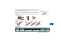
Unpacking and product confirmation
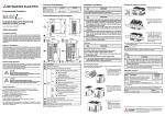
Take the plug-in option out of the package, check the product name, and confirm that the product is as you ordered and intact.
This product is a plug-in option dedicated for the FR-A800 series.
Product confirmation
Check the enclosed items.
Plug-in option
...............................................1
1
2
Mounting screw (M3 × 8 mm)
.....................2 (Refer to page 7.)
Spacer
....................2 (Refer to page 7.)
1
O
N
SW2
SW1
1
2
3
4
O
N
SW3
NOTE
• Connection diagrams in this Instruction Manual appear with the control logic of the input terminals as sink logic, unless
otherwise specified. (For the control logic, refer to the Instrucution Manual(Detailed) of the inverter.)
PRE-OPERATION INSTRUCTIONS
5
1.2
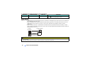
Component names
Front view
Terminal layout
(a)
Rear view
(g)
(a)
(a)
(d)
(f)
1
2
O
N
PA1
PB1
PZ1
PG
PG
PIN
SW2
O
N
SW3
1
2
3
4
(c)
(e)
SW1
PA2
PB2
PZ2
SD
SD
PO
PIN and PO
are not used.
(a)
(a)
(b)
Symbol
Name
(a)
Refer to
page
Description
a
Mounting hole
Fixes the option to the inverter with screws, or installs spacers.
7
b
Terminal block
Connects to the encoder.
12
c
Encoder type selection switch (SW3)
Switches the encoder type (differential line driver/ complementary).
10
d
CON2 connector
Not used.
―
e
Terminating resistor selection switch
(SW1)
Switches ON or OFF the internal terminating resistor.
f
Switch for manufacturer setting (SW2)
Do not change the initially-set status. (Switches 1 and 2 are OFF
g
Connector
Connects to the option connector of the inverter.
6
PRE-OPERATION INSTRUCTIONS
10
1
2
O
N
.)
―
7
2
2.1
INSTALLATION AND WIRING
Pre-installation instructions
Check that the inverter's input power and the control circuit power are both OFF.
Caution
Do not mount or remove the plug-in option while the input power is ON. Doing so may damage the inverter or plug-in option.
To avoid damage due to static electricity, static electricity in your body must be discharged before you touch the product.
2.2
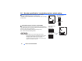
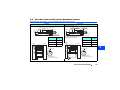
Installation procedure
(1) Remove the inverter front cover. (Refer to Chapter 2 of the
Instruction Manual (Detailed) of the inverter for details on how to
remove the front cover.)
(2) For the two mounting holes (as shown in the next page) that will not
be tightened with mounting screws, insert spacers.
(3) Fit the connector of the plug-in option along the guide of the
connector on the inverter, and insert the plug-in option as far as it
goes. (Insert it to the inverter option connector 1 or 2.)
(4) Fit the two locations, the left and right, of the plug-in option securely
to the inverter unit by screwing in the supplied mounting screws
(tightening torque 0.33 N·m to 0.40 N·m). If the screw holes do not
line up, the connector may not be inserted deep enough. Check the
connector.
Inverter side
option connector
Spacer
2
Spacer
Example of installation to connector 1
INSTALLATION AND WIRING
7
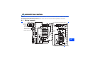
Do not insert the plug-in option to the connector 3.
Connector 3
Mounting screw
Spacer
Spacer
Connector 2
Spacer
Mounting screw
Connector 1
Spacer
Mounting screw
Insertion positions for screws and spacers
8
INSTALLATION AND WIRING
NOTE
• Caution must be taken of mounting screws falling off when removing and mounting the plug-in option.
• Only one type of option per inverter may be used. When multiple options are mounted, priority is given to option
connectors 1, 2 and 3 on the inverter in this order, and options having a lower priority do not function. (For the
positions of the option connectors 1 to 3, refer to page 8.)
• When the inverter cannot recognize that the option unit is mounted due to improper installation, etc., the protective
function (E.1 to E.3) is displayed. A different indication will appear according to the mounted position (option connector
1 to 3).
Mounted position
Fault indication
Option connector 1
Option connector 2
Option connector 3
• When removing the plug-in option, remove the two screws on the left and right, then pull it straight out. Pressure
applied to the connector and to the option board may break the option.
INSTALLATION AND WIRING
2
9
2.3
Encoder specification / terminating resistor switch setting
Encoder specification selection switch (SW3)
Differential line driver
(initial status)
Select either differential line driver or complementary.
It is initially set to the differential line driver. Switch its position according
to output circuit.
1
2
O
N
SW2
SW1
1
2
3
4
O
N
SW3
Terminating resistor selection switch (SW1)
Select "ON"/"OFF" of the internal terminating resistor. Set the switch to
"ON" (initial status) when an encoder output type is differential line driver
and set to "OFF" when complementary.
ON : with internal terminating resistor (initial setting status)
OFF : without internal terminating resistor
Complementary
Internal terminating
resistor-ON
(initial status)
1
2
O
N
SW2
NOTE
• Set all switches to the same setting ("ON"/ "OFF").
• If the encoder output type is differential line driver, set the
terminating resistor switch to the "OFF" position when
sharing the same encoder with other unit (CNC
(computerized numerical controller), etc) or a terminating
resistor is connected to other unit.
10
INSTALLATION AND WIRING
Internal terminating
resistor-OFF
SW1
1
2
3
4
O
N
SW3
Motor used and switch setting
Encoder specification
selection switch (SW3)
Motor
Mitsubishi standard motor with
encoder
Mitsubishi high-efficiency motor
with encoder
Mitsubishi constant-torque motor
with encoder
Vector control dedicated motor
Power
specifications
SF-JR
Differential
ON
5V
SF-HR
Differential
ON
5V
Others
SF-JRCA
Differential
ON
5V
SF-HRCA
Differential
ON
5V
Others
SF-V5RU
Complementary
OFF
12 V
Other manufacturer's motor with encoder
Terminating resistor
selection switch (SW1)
Set according to the motor encoder used.
Choose a power supply for encoder according to the encoder used (5 V/12 V/15 V/24 V).
When the encoder output is the differential line driver type, only 5 V can be input.
NOTE
2
• Switch "SW2" is for manufacturer setting. Do not change the setting.
INSTALLATION AND WIRING
11
2.4
Wiring
(1) Use twisted pair shield cables (0.2 mm2 or larger) to connect the FR-A8AP and position detector.
For the wiring to the terminals PG and SD, use several cables in parallel or use a
Example of parallel connection
thick cable, according to the wiring length. To protect the cables from noise, run
with two cables
them away from any source of noise (e.g. the main circuit and power voltage).
(with complementary encoder output)
Wiring length
Parallel connection
(Cable gauge 0.2 mm2)
Larger-size cable
Within 10 m
At least two cables in parallel
0.4 mm2 or larger
Within 20 m
At least four cables in parallel
0.75 mm2 or larger
Within 100 m
At least six cables in parallel
1.25 mm2 or larger
FR-A800
(FR-A8AP)
When differential driver is set and a wiring length is 30 m or more
The wiring length can be extended to 100 m by slightly increasing the 5 V power
supply (approx. 5.5 V) and using six or more cables with gauge size of 0.2 mm2 in
parallel or a cable with gauge size of 1.25 mm2 or more. Note that the voltage
applied should be within power supply specifications of encoder.
To reduce noise of the encoder cable, earth (ground) the encoder shielded
cable to the enclosure (as close as the inverter) with a P clip or U clip
made of metal.
Encoder
PA1
PA2
PB1
PB2
PZ1
PZ2
A
B
C
D
F
G
PG
SD
S
R
2mm2
Earthing (grounding) example using a P clip
Encoder cable
Shield
P clip
NOTE
• For details of the optional encoder dedicated cable (FR-JCBL/FR-V7CBL), refer to page 15.
• FR-V7CBL is provided with a P clip for earthing (grounding) shielded cable.
12
INSTALLATION AND WIRING
(2) Wire the shielded twisted pair cable after stripping its sheath to make its cables loose.
Also, protect the shielded cable of the shielded twisted pair cable to ensure that it will
Shield
not make contact with the conductive area.
(perform protective treatment)
Strip off the sheath for the below length. If the length of the sheath peeled is too long, a
short circuit may occur with neighboring wires. If the length is too short, wires might
come off.
Wire the stripped cable after twisting it to prevent it from becoming loose. In addition,
do not solder it.
Cable stripping length
Sheath
Shielded twisted pair cable
5 mm
Use a ferrule terminal as necessary.
When using the ferrule terminal, use care so that the twisted wires do not come
ve
ee
Sl
Unstranded
wires
ire
W
2
m
.5m
o0
0t
Damaged
Crumpled tip
Wires are not inserted
into the sleeve
NOTE
• Ferrule terminals commercially available (as of February 2012. The product may be changed without notice.)
Terminal
Screw Size
M2
Wire Size (mm2)
0.3 to 0.5
Ferrule Terminal Model
with insulation sleeve
Al 0,5-6WH
without insulation sleeve
A 0,5-6
Manufacturer
Phoenix Contact
Co.,Ltd.
Ferrule terminal
crimping tool
CRIMPFOX 6
INSTALLATION AND WIRING
13
(3) Loosen the terminal screw and insert the cable into the terminal.
Screw Size
Tightening Torque
0.22 Nm to 0.25 Nm
M2
Cable Size
0.3 mm2 to 0.75 mm2
Screwdriver
Small
flat-blade screwdriver
(Tip thickness: 0.4 mm/tip width: 2.5 mm )
NOTE
• Undertightening can cause cable disconnection or malfunction. Overtightening can cause a short circuit or malfunction
due to damage to the screw or unit.
• When wiring cables to the inverter's RS-485 terminals while a plug-in option is mounted, take caution not to let the
cables touch the circuit board of the option or of the inverter. Otherwise, electromagnetic noises may cause
malfunctions.
• When one position detector is shared between FR-A8AP and CNC (computerized numerical controller), its output
signal should be connected as shown below. In this case, the wiring length between FR-A8AP and CNC should be as
short as possible, within 5 m.
Inverter
(FR-A8AP)
Position detector
Encoder
CNC
Maximum 5 m
(two parallel cables)
CAUTION
14
Do not use empty terminals as junction terminals because they are used in the option unit. If they are used as the junction terminals, the option unit
may be damaged.
After wiring, wire offcuts must not be left in the inverter. They may cause a fault, failure or malfunction.
INSTALLATION AND WIRING
2.5
Encoder cables dedicated to Mitsubishi motors
Use dedicated encoder cables to connect with Mitsubishi encoder-equipped motors.
FR-JCBL
FR-V7CBL
For SF-V5RU and SF-THY
For SF-JR/HR/JRCA/HRCA (with encoder)
F-DPEVSB 12P 0.2 mm2
Approx. 140 mm
11mm
Earth cable
Earth cable
D/MS3057-12A
11mm
2
F-DPEVSB 12P 0.2mm
D/MS3057-12A
Approx. 140 mm
60mm
60mm
L
Type
FR-A800
(FR-A8AP)
Encoder
PA1
PA2
PB1
PB2
PZ1
PZ2
C
R
A
N
B
P
PG
SD
H
K
Length
L (m)
FR-JCBL5
5
FR-JCBL15
15
FR-JCBL30
30
Positioning keyway
A B
N
C
P D
T
K S
E
R
J
H G F
M
2mm
2
L
D/MS3106B20-29S
(As viewed from wiring side)
D/MS3106B20-29S
L
D/MS3106B20-29S
• A P clip for earthing (grounding) a
shielded cable is provided.
FR-A800
(FR-A8AP)
Encoder
PA1
PA2
PB1
PB2
PZ1
PZ2
A
B
C
D
F
G
PG
SD
S
R
Type
Length
L (m)
FR-V7CBL5
5
FR-V7CBL15
15
FR-V7CBL30
30
2
Positioning keyway
M A B
N
C
L
P D
T
K
E
S
R
J
H G F
D/MS3106B20-29S
(As viewed from wiring side)
2mm2
As the terminal block of the FR-A8AP is an insertion type, earth (ground) cables need to be modified. (Refer to page 13.)
INSTALLATION AND WIRING
15
Connection terminal compatibility table
Motor
SF-JR/HR/JRCA/HRCA (with Encoder)
Encoder cable
FR-JCBL
PA1
FR-A8AP terminal
2.6
FR-V7CBL
PA
PA
PA2
PAR
Keep this open.
PB1
PB
PB
PB2
PBR
Keep this open.
PZ1
PZ
PZ
PZ2
PZR
Keep this open.
PG
5E
PG
SD
AG2
SD
Terminals
Terminal
Symbol
Terminal Name
PA1
Encoder A-phase signal input terminal
PA2
Encoder A-phase inverse signal input terminal
PB1
Encoder B-phase signal input terminal
PB2
Encoder B-phase inverse signal input terminal
PZ1
Encoder Z-phase signal input terminal
PZ2
Encoder Z-phase inverse signal input terminal
PG
Encoder power supply (positive side) input
terminal
SD
Encoder power supply ground terminal
16
SF-V5RU, SF-THY
INSTALLATION AND WIRING
Description
A-phase signal is input from the encoder.
B-phase signal is input from the encoder.
For details of pulse signal,
refer to page 17.
Z-phase signal is input from the encoder.
(Not used for the encoder feedback control.)
Input power for the encoder power supply.
Connect the external power supply (5 V, 12 V, 15 V, 24 V) and the encoder
power cable. When the encoder output is the differential line driver type, only 5
V can be input. Make sure the voltage of the external power supply the same
as the encoder output voltage. (Check the encoder specification.)
3
3.1
ENCODER SPECIFICATIONS AND PARAMETER SETTINGS
Encoder
Position detection (pulse encoder)
Output pulse specifications
Differential line driver
Complementary
A/A signal 1000 P/R to 4096 P/R
B/B signal 1000 P/R to 4096 P/R
Z/Z signal 1 P/R
P
a b c d
H
A
L
A
B
B
Z
Z
A signal 1000 P/R to 4096 P/R
B signal 1000 P/R to 4096 P/R
Z signal 1 P/R
P
a b c d
Position detector
Encoder
A
A
B
Z
When rotation is clockwise
as viewed from the shaft
end (A) of the encoder.
a, b, c, d should be (1/4
1/8)P
NOTE
• When orientation control, encoder feedback control, vector control are used together, the encoder is shared between
these controls.
Use an encoder which has a pulse count of 1000 to 4096 ppr (pulse per revolution).
• The encoder should be coupled with the motor shaft or the spindle oriented with a speed ratio of 1 to 1 without any
mechanical looseness.
• To ensure correct operation, the encoder must be set in the proper rotation direction and the A and B phases
connected correctly.
ENCODER SPECIFICATIONS AND PARAMETER SETTINGS
17
3
Power supply
Choose a power supply for encoder according to the encoder used (5 V/12 V/15 V/24 V). When the encoder output is the
differential line driver type, only 5 V can be input. Make sure the voltage of the external power supply the same as the encoder
output voltage. (Check the encoder specification.)
When an encoder is used under orientation control, encoder feedback control, and vector control, the power supply is shared
between the inverter and encoder.
• Specifications of the encoders equipped in the motors with encoders and the vector-control dedicated motors
Item
Encoder for SF-JR/HR/JRCA/HRCA
Encoder for SF-V5RU, SF-THY
Resolution
1024 pulses/rev
2048 pulses/rev
Power supply voltage
5 VDC±10%
12 VDC±10%
Current consumption
150 mA
Output signal form
A, B phases (90° phase shift)
Z phase: 1 pulse/rev
Output circuit
Differential line driver 74LS113 equivalent
Complementary
Output voltage
H level: 2.4 V or more
L level: 0.5 V or less
H level: "Power supply for encoder-3 V" or more
L level: 3 V or less
NOTE
• When the input power supply voltage to the encoder and its output voltage differ, the protective function (E.ECT) may
be activated.
18
ENCODER SPECIFICATIONS AND PARAMETER SETTINGS
3.2
Parameter setting
3.2.1
Parameter for encoder
Parameter
Number
Pr.
group
Initial
Value
Name
Setting
Range
0
100
359
C141
Encoder rotation
direction
1
1
101
369
C140
Number of
encoder pulses
1024
0 to 4096
Description
Set when using a motor for which
forward rotation (encoder) is clockwise
(CW) viewed from the shaft
CW
Set when using a motor for which
forward rotation (encoder) is
counterclockwise (CCW) viewed from
the shaft
CCW
Set for the operation
at 120 Hz or less.
Set for the operation
at a frequency
higher than 120 Hz.
Set for the operation
at 120 Hz or less.
Set for the operation
at a frequency
higher than 120 Hz.
Set the number of encoder pulses output.
Set the number of pulses before it is multiplied by 4.
3
NOTE
• If operating at a frequency higher than 120 Hz with Pr.359 = "0 or 1", the motor rotation will be unstable.
ENCODER SPECIFICATIONS AND PARAMETER SETTINGS
19
3.2.2
Parameter settings for the motor under vector control
Motor Name
SF-JR
Mitsubishi standard motor
Pr.359 Encoder rotation
direction
1 (Initial value)
Pr.369 Number of
encoder pulses
1024 (Initial value)
SF-JR 4P 1.5 kW or less
1 (Initial value)
1024 (Initial value)
SF-HR
1 (Initial value)
1024 (Initial value)
Others
SF-JRCA 4P
1 (Initial value)
1024 (Initial value)
SF-HRCA 4P
1 (Initial value)
1024 (Initial value)
Others
SF-V5RU
1 (Initial value)
2048
SF-THY
1 (Initial value)
2048
Other manufacturer's standard
motor
—
Other manufacturer's constanttorque motor
—
Mitsubishi constant-torque
motor
Mitsubishi vector control
dedicated motor
20
Set this parameter according to the motor (encoder) used.
ENCODER SPECIFICATIONS AND PARAMETER SETTINGS
4
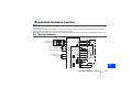
ORIENTATION CONTROL
This function is used with a position detector (encoder) installed to the spindle of a machine tool, etc. to allow a rotary shaft to
be stopped at the specified position (oriented).
For the details of the parameters used for orientation control, refer to the Instruction Manual (Detailed) of the inverter.
4.1
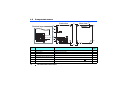
Wiring example
MCCB
Three-phase
AC power
supply
Forward rotation start
Reverse rotation start
Orientation command
Contact input common
MC
SF-JR motor with encoder
For complementary type (SF-V5RU)
U
MCCB
MC
OCR
SF-V5RU
V
∗1
IM
Three-phase
W
FAN
AC power
supply
E
Inverter
R/L1
S/L2
T/L3
STF
STR
X22∗3
SD
ORA∗4
U
V
W
FR-A8AP
PA1
Earth
(Ground)
C
A
PB2
N
PZ1
PZ2
Differential
B
PG
FR-A8AX
SD
Complementary
X15 ∗10
PG
X14
Terminating SD
resistor ON
X1
∗8
∗7
X0
OFF
DY
∗4
SE
SD
PC
External
thermal relay
input ∗11
Encoder
Earth
(Ground)
2 W1 kΩ
OH
G1
SD
G2
FR-A8AP PA1
A
PA2
B
H
PB1
C
K
PB2
D
PZ1
PZ2
G
PG
S
SD
R
P
∗5
Differential
∗6
(+)
U
V
W
E
U
V
W
R
PA2
PB1
ORM
Inverter
∗2
(-) 5 VDC power
supply ∗9
Complementary
Terminating
resistor ON
Thermal
relay
protector
∗2
Encoder
F
4
∗5
PG
SD
OFF
IM
∗7 ∗8
∗6
(+)
(-) 12 VDC power
supply ∗9
ORIENTATION CONTROL
21
For the fan of the 7.5 kW or less dedicated motor, the power supply is single phase (200 V/50 Hz, 200 to 230 V/ 60 Hz).
The pin number differs according to the encoder used.
Use Pr. 178 to Pr. 189 (input terminal function selection) to assign the function to any of terminal.
Refer to the Instruction Manual (Detailed) for details of Pr. 178 to Pr. 189 (input terminal function selection).
Use Pr. 190 to Pr. 196 (output terminal function selection) to assign the function to any of terminal.
Refer to the Instruction Manual (Detailed) for details of Pr. 190 to Pr. 196 (output terminal function selection).
Connect the encoder so that there is no looseness between the motor and motor shaft. Speed ratio should be 1:1.
Earth (Ground) the shielded cable of the encoder cable to the enclosure with a P clip, etc. (Refer to page 12.)
For the differential line driver, set the terminating resistor selection switch to on position (initial status) to use. (Refer to page 10.)
Note that the terminating resistor switch should be set to off position when sharing the same encoder with other unit (CNC, etc.) and a
terminating resistor is connected to other unit. For the complementary, set the switch to off position.
For terminal compatibility of the FR-JCBL, FR-V7CBL and FR-A8AP, refer to page 16.
A separate power supply of 5 V/12 V/15 V/24 V is necessary according to the encoder power specification. When the encoder output is
the differential line driver type, only 5 V can be input.
Make the voltage of the external power supply the same as the encoder output voltage, and connect the external power supply between
PG and SD.
When performing encoder feedback control and vector control together, an encoder and power can be shared.
When a stop position command is input from outside, a plug-in option FR-A8AX is necessary. Refer to the Instruction Manual (Detailed)
for details of external stop position command.
To use a terminal as the terminal OH, assign the OH (external thermal O/L relay input) signal to an input terminal. (Set "7" in any of Pr.178
to Pr.189. For details, refer to the Instruction Manual (Detailed) of the inverter.)
22
ORIENTATION CONTROL
4.2
Terminals
Option FR-A8AX terminal
Terminal
Symbol
Terminal Name
Description
X0 to X15
Digital signal input terminal
Input the digital signal at the relay contact or open collector terminal.
Using Pr. 360, speed or position command is selected as the command signal entered.
DY
Data read timing input signal
terminal
Used when a digital signal read timing signal is necessary. Data is read only during the DY
signal is on.
By switching the DY signal off, the X0 to X15 data before signal-off is retained.
Inverter terminal
Terminal
(Signal)
Input
Terminal (Signal) Name
Application Explanation
X22
Orientation command
Used to enter an orientation signal for orientation.
For the terminal used for X22 signal input, set "22" in any of Pr. 178 to Pr. 189 to assign
the function.
ORA
Orientation complete
Switched LOW if the orientation has stopped within the in-position zone while the start
and X22 signals are input.
For the terminal used for the ORA signal output, assign the function by setting "27
(positive logic) or 127 (negative logic)" in any of Pr. 190 to Pr. 196.
ORM
Orientation fault
Switched LOW if the orientation has not completed within the in-position zone while the
start and X22 signals are input.
For the terminal used for the ORA signal output, assign the function by setting "28
(positive logic) or 128 (negative logic)" in any of Pr. 190 to Pr. 196.
Output
Refer to the Instruction Manual (Detailed) for details of Pr.178 to Pr.189 (input terminal function selection) and Pr.190 to Pr.196
(output terminal function selection).
ORIENTATION CONTROL
23
4
4.3
Specifications
Repeated positioning
accuracy
Permissible speed
Functions
Holding force after
positioning
Input signal
(contact input)
Output signal
(open collector output)
24
±1.5°
Depends on the load torque, moment of inertia of the load or orientaion, creep speed, position loop switching
position, etc.
Encoder-mounted shaft speed (6000 r/min with 1024 pulse encoder).
The drive shaft and encoder-mounted shaft must be coupled directly or via a belt without any slip.
Gear changing shafts cannot be applied.
Orientation, creep speed setting, stop position command selection, DC injection brake start position setting,
creep speed and position loop switch position setting, position shift, orientation in-position, position pulse
monitor, etc.
Under V/F control, Advanced magnetic flux vector control...without servo lock function
Under vector control...with servo lock function
Orientation command, forward and reverse rotation commands, stop position command (open collector signal
input (complementary) is enabled)
Binary signal of maximum 16 bit (when used with the FR-A8AX)
Orientation completion signal, orientation fault signal
ORIENTATION CONTROL
5
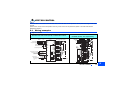
ENCODER FEEDBACK CONTROL
Mount FR-A8AP to an FR-A800 series inverter to perform encoder feedback control under V/F control or Advanced magnetic
flux vector control.
This controls the inverter output frequency so that the motor speed is constant to the load variation by detecting the motor
speed with the speed detector (encoder) to feed back to the inverter.
For the details of the parameters used for encoder feedback control, refer to the Instruction Manual (Detailed) of the inverter.
5.1
Wiring examples
MCCB
Three-phase
AC power supply
Forward rotation start
Reverse rotation start
Contact input common
Frequency setting
potentiometer
MC
Inverter
R/L1
S/L2
T/L3
STF
STR
U
V
W
FR-A8AP
PA1
SD
10
Earth
(Ground)
C
Differential
Terminating
resistor ON
∗4
A
PB1
N
PB2
PG
Complementary
∗1
R
PA2
2
5
SF-JR motor with encoder
U
V
IM
W
E
H
SD
K
Encoder
∗2
PG
SD
∗5
∗3
(+)
(-) 5 VDC power
supply ∗6
5
OFF
ENCODER FEEDBACK CONTROL
25
5.2
The pin number differs according to the encoder used.
Connect the encoder so that there is no looseness between the motor and motor shaft. Speed ratio should be 1:1.
Earth (Ground) the shielded cable of the encoder cable to the enclosure with a P clip, etc. (Refer to page 12.)
For the differential line driver, set the terminating resistor selection switch to on position (initial status) to use. (Refer to page 10) Note that
the terminating resistor switch should be set to off position when sharing the same encoder with other unit (CNC, etc) and a terminating
resistor is connected to other unit.
For the complementary, set the switch to off position.
For terminal compatibility of the FR-JCBL, FR-V7CBL and FR-A8AP, refer to page 16.
A separate power supply of 5 V/12 V/15 V/24 V is necessary according to the encoder power specification. When the encoder output is
the differential line driver type, only 5 V can be input.
Make the voltage of the external power supply the same as the encoder output voltage, and connect the external
power supply between PG and SD.
To perform orientation control together, an encoder and power supply can be shared.
Specifications
Speed variation ratio
Function
Maximum speed
26
0.1% (100% means 3600 r/min)
• Setting of speed feedback range
• Setting of feedback gain
• Setting of encoder rotation direction
V/F control: 590 Hz, Advanced magnetic flux vector control: 400 Hz (102400 pulse/s or less encoder pulses)
ENCODER FEEDBACK CONTROL
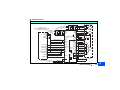
6
VECTOR CONTROL
When FR-A8AP is mounterd on the FR-A800 series, full-scale vector control operation can be performed using a motor with
encoder.
Speed control, torque control and position control by vector control can be performed. (Refer to the Instruction Manual
(Detailed) for details.)
6.1
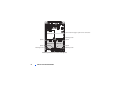
Wiring examples
Speed control
Standard motor with encoder (SF-JR), 5 V differential line driver
MCCB
Three-phase
AC power supply
MC
Inverter
U
V
W
R/L1
S/L2
T/L3
SF-JR motor with encoder
U
V
IM
W
Vector control dedicated motor
(SF-V5RU, SF-THY), 12 V complementary
MCCB
*7
STF
STR
Contact input common
SD
Frequency command 3
2
Frequency setting
potentiometer
1/2 W1 kΩ 1
Torque limit
command (+)
(-)
( 10 V)
10
FR-A8AP
PA1
Differential
2
5
1
Earth
(Ground)
C
R
PA2
PB1
A
PB2
N
PZ1
PZ2
B
Complementary
P
PG
H
SD
Terminating
resistor ON PG
K
SD
OFF
∗4
∗6
∗3
(+)
∗1
PC
OH
SD
FR-A8AP
PA1
External
thermal
relay input *8
Encoder
∗2
(-) 5 VDC power supply
∗5
OCR
U
V
W
Inverter
E
Forward rotation start
Reverse rotation start
MC
Three-phase
AC power
supply
SF-V5RU, SF-THY
A
B
C
U
V
W
E
Earth
(Ground)
G1
G2
2W1kΩ
A
PA2
B
PB1
C
PB2
D
Differential PZ1
F
PZ2
G
Complementary
PG
S
Terminating
resistor
ON
PG
SD
*6
IM
Thermal relay
protector
*1
Encoder
*2
R
SD
*4
OFF
FAN
*3
(+)
12VDC power
(-) supply
*5
VECTOR CONTROL
27
6
Torque control
Standard motor with encoder (SF-JR), 5 V differential line driver
MCCB
Three-phase
AC power
supply
MC
Inverter
R/L1
S/L2
T/L3
STF
FR-A8AP
STR
PA1
Contact input common
PA2
Speed limit command 3
2
Frequency setting
potentiometer
1/2W1kΩ 1
Torque command (+)
(±10V) (-)
10
A
N
1
Complementary
Terminating
resistor ON
VECTOR CONTROL
∗1
PZ1
PZ2
B
PG
H
SD
K
P
∗6
(+)
Inverter
Encoder
∗2
∗3
(-) 5VDC power supply
∗5
MC
OCR
U
V
W
PC
OH
SD
FR-A8AP
PA1
PG
SD
MCCB
*7
Three-phase
AC power
supply
External
thermal
relay input *8
R
PB2
2
5
Earth
(Ground)
C
PB1
Differential
OFF
∗4
28
U
V
W
Forward rotation start
Reverse rotation start
SD
SF-JR motor
with encoder
U
V
IM
W
E
Vector control dedicated motor
(SF-V5RU, SF-THY), 12 V complementary
SF-V5RU, SF-THY
A
B
C
Earth
(Ground)
G1
G2
2W1kΩ
A
PA2
B
PB1
C
PB2
D
Differential PZ1
F
PZ2
G
Complementary
PG
S
Terminating
resistor
ON
PG
SD
*6
IM
Thermal relay
protector
*1
Encoder
R
SD
*4
OFF
FAN
U
V
W
E
*3
(+)
12VDC power
(-) supply
*5
*2
Position control
Vector control dedicated motor (SF-V5RU, SF-THY), 12 V complementary
MCCB
MC
OCR
SF-V5RU, SF-THY
A
B
C
∗7
Positioning unit
MELSEC-Q QD75P[ ]N/QD75P[ ]
MELSEC-L LD75P[ ]
Three-phase
AC power
supply
FLS
RLS
Three-phase
AC power supply
MCCB
MC
R/L1
S/L2
T/L3
DOG
STOP
Forward stroke end
Reverse stroke end
Pre-excitation/servo on
Clear signal
Pulse train
PULSE F
Sign signal
24VDC power supply
PULSE R
PA2
B
CLR ∗9
PB1
C
PB2
D
PZ1
PZ2
F
NP ∗9
PULSE COM
SE
Differential
line driver
A
G
Complementary
PG
S
Terminating
resistor
ON
SD
R
RDYCOM
COM
RDY ∗11
5
∗1
Encoder
∗2
PG
SD
∗4
Thermal
protector
G1
G2
2W1kΩ
LX ∗9
JOG ∗10
IM
Earth
(ground)
SD
FR-A8AP
PA1
PC
Preparation ready signal
U
V
W
E
STF
STR
CLRCOM
READY
U
V
W
Inverter
External thermal protector PC
relay input ∗8
OH
CLEAR
FAN
∗6
∗3
(+)
12VDC
(-) power supply ∗5
OFF
Torque limit command (+)
(±10V) (-)
1
VECTOR CONTROL
29
6
The pin number differs according to the encoder used.
Speed, control, torque control, and position control by pulse train input are available with or without the Z-phase being connected.
Connect the encoder so that there is no looseness between the motor and motor shaft. Speed ratio must be 1:1.
Earth (ground) the shield of the encoder cable to the enclosure using a tool such as a P-clip. (Refer to page 12.)
For the complementary, set the terminating resistor selection switch to OFF position. (Refer to page 10.)
A separate power supply of 5 V/12 V/15 V/24 V is necessary according to the encoder power specification.
When the encoder output is the differential line driver type, only 5 V can be input.
Make the voltage of the external power supply the same as the encoder output voltage, and connect the external power supply across PG
and SD.
When performing orientation control together, an encoder and power supply can be shared.
For terminal compatibility of the FR-JCBL, FR-V7CBL, and FR-A8AP, refer to page 16.
For the fan of the 7.5 kW or lower dedicated motor, the power supply is single phase. (200 V/50 Hz, 200 to 230 V/60 Hz)
To use a terminal as the terminal OH, assign the OH (external thermal O/L relay input) signal to an input terminal. (Set "7" in any of Pr.178
to Pr.189. For details, refer to the Instruction Manual (Detailed) of the inverter.)
Assign the function using Pr.178 to Pr.184, Pr.187 to Pr.189 (input terminal function selection).
When position control is selected, terminal JOG function is invalid and simple position pulse train input terminal becomes valid.
Assign the function using Pr.190 to Pr.194 (output terminal function selection).
30
VECTOR CONTROL
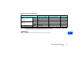
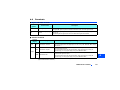
6.2
Specifications
Speed control
Torque control
Position control
Speed control range
1:1500 (both driving/regeneration )
Speed variation ratio
±0.01% (100% means 3000 r/min)
Speed response
130 Hz
Maximum speed
120 Hz (102400 pulse/s or less encoder pulses)
Torque control range
1:50
Absolute torque accuracy
±10%
Repeated torque accuracy
±5%
Repeated positioning
accuracy
±1.5° (at motor shaft end)
Maximum input pulse
frequency
100 kpps (Terminal JOG)
Positioning feedback
pulse
Number of encoder pulses per motor rotation (Pr.369) 4
Electronic gear setting
1/50 to 20
In-position width
0 to 32767 pulses
Error excess
0 to 400k pulses
• Setting of speed feedback range
• Setting of feedback gain
• Setting of encoder rotation direction
Function
Regeneration unit (option) is necessary for regeneration
With online auto tuning (adaptive magnetic flux observer), dedicated motor, rated load
VECTOR CONTROL
31
6
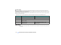
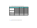
REVISIONS
*The manual number is given on the bottom left of the back cover.
Print Date
*Manual Number
Revision
Aug. 2013
IB(NA)-0600505ENG-A
First edition
Sep. 2014
IB(NA)-0600505ENG-B
Modification
Ferrule terminals commercially available
32
IB(NA)-0600505ENG-B
INVERTER
HEAD OFFICE: TOKYO BUILDING 2-7-3, MARUNOUCHI, CHIYODA-KU, TOKYO 100-8310, JAPAN
IB(NA)-0600505ENG-B(1409) MEE
Printed in Japan
Specifications subject to change without notice.