1
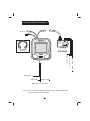
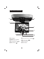
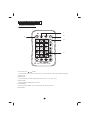
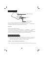
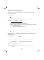
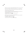
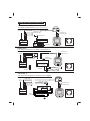
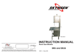
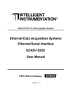
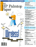
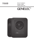
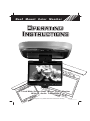
Ro o f
Mount Color Monitor
IR
TR
I RA N S M
ITT
AN
SM
ITT
ER
ER
TR
7-inch Wide Screen Roof Mount Color Monitor
With IR Audio Transmitter
ON/O
/OF
FF
F
Before operating the unit, please read these instructions carefully
ON
OT01003512-20011128
General Information
TABLE OF CONTENTS
General Information
W elcome
.............................................................................. 1
Precautions
........................................................................ 1
Important Notes
................................................................... 2
Installation Guide
Precautions
.......................................................................... 3
Electrical Connections
....................................................... 4
Signal Connections
.......................................................... 4
T ypical Wiring Diagram .................................................. 5
Main Unit
Function K
eys
........................................................... 6
Remote Control Unit
Frequently Used Buttons
................................................... 7
Replacement of Battery ....................................................... 8
Precautions
................................................................... 8
Operating the Monitor
Eject / Open the Display Monitor
.................................... 8
K eeping the Display Monitor ........................................... 9
Display F ormat .................................................................. 9
Signal Source ON / OFF(MODE) ....................................... 9
Function Mode (MENU)
.................................................. 9
Mute Function (Remote Control) ........................................ 10
Door Light ON / OFF
......................................................... 10
General Information
Courtesy Light ON / OFF .......................................... 10
Accessories Supplied
Technical Specifications
.................................................. 11
.................................................. 12
System Configuration .......................................................... 13
WELCOME
Thank you for the purchase of this Roof Mount Color Monitor. Before operating
the unit, please read this manual thoroughly and retain it for future reference.
PRECAUTIONS
To prevent short-circuiting of the electrical system and cause serious damage to the
unit or the vehicle, you are advised to follow the instructions carefully.
* Should there be requirement to replace blown fuse, do remember to disconnect
all power supply and switched off the unit before replacing it with a new one. Use
only correct rating fuse to avoid damaging the unit.
* During operation, if there is symptom of over-heating or system mal-function, do
switch off the unit and consult your dealer immediately. Please do not attempt to
open up the unit since there is no serviceable parts inside.
To avoid damaging the LCD panel and cause serious injury to you or others, please
observe the followings:
* Do not drop the LCD display panel or subject it to direct impact.
* Should the LCD panel is broken, do avoid all human contact to the broken glasses
or fluid leaked out from the enclosure. If come into contact, do flush and clean
affected areas with plenty of water. Seek medical attention immediately.
This unit is designed using high quality electronic components and manufactured
under stringent quality control system. The system unit will provide many hours of
quality performance if use correctly. Do follow the maintenance procedure below:
* The battery life of the remote control unit is about six months long. To ensure
effective control, please replace the batteries regularly. Do not use new and used
batteries at the same time to avoid damaging the good battery.
* Do not use any chemical solvent, cleaning agent or corrosive detergent to clean
away dirt on the surface of the screen. By so doing, you may cause irreversible
damage to the surface of the TFT screen. To clean off dirt or fingerprints, we
recommend the use of a soft damp lens cleaning cloth.
* Do not drop the monitor or hit it with hard object. It may cause permanent
damage to the LCD panel or the back light element.
1
* When operating the display unit, do avoid touching or pressing the LCD glass
panel. Excessive force may cause irreparable damage to the LCD screen.
* Ensure no metal or foreign materials are dropped in between the display screen
and enclosure. Obstacles may impeach smooth running of the tray and may cause
electrical shorts.
IMPORTANT NOTES:
* When use in conjunction with Radio / TV tuner , please do note that these TV
receivers are manufactured to receive television broadcast signals that are
transmitted via terrestrial radio waves. Reception quality will change and vary
according to geographical location and climatic condition.
* To avoid accident, we strongly advise not to install the display screen at a position
that will distract the attentiveness of the driver.
* Do avoid installing the monitor screen at a position that is under direct sunlight
and place monitor away from hot air vent. Please note that the normal working
temperature of TFT screen is between 0¢XC to 60¢XC. If the internal temperature of
the vehicle is extremely high, do allow a short cooling down period before operating
the unit.
* Installed unit at a dry location away from condensation.
* Use only correct size of fasteners or connection cable during installation. Failure
to comply with this requirement may damage the mechanical structure or create fire
hazard.
* Kindly refer to authorized dealers if in doubts.
* To avoid electrical shock, do not open the enclosure. High voltage is present. No
user serviceable parts inside the enclosure.
* The picture quality of this display monitor is restricted by the LCD design. To
achieve best picture quality, adjust the brightness control or viewing angle of the
unit till optimum level.
Before installing this display system, please check that you are in compliance
with your local traffic rules and regulations
2
INSTALLATION GUIDE
Precautions:
1. This unit should be install by qualified technician or service personnel.
2. This product is designed to operate with a 12V DC, negative ground
battery system.
3. Disconnect the ground wire from the battery terminal before connecting
this unit to the electrical system.
4. The wiring from some other products or accessories might bear similar
color code to this product but however they might of different function.
It is always advisable to refer to the electrical connection diagrams of
products or accessories before installation to avoid wrong connection.
5. Use proper insulation and fastening materials to prevent electrical
short-circuiting.
6. Do not connect the yellow wire of this product directly to the battery
terminal. Do remember to connect the red wire of this product to the
ACC of the ignition key switch. Failure to do so may result in draining
off the battery charge prematurely.
7. Use only supplied accessories to avoid damaging the unit during
installation.
8. Do not install this product at a position that may cause injuries to the
passenger(s) during an accident.
9. However, due to different car specification, kindly ensure that the display
monitor is suitably located such that it is not obstructing the rear view
mirror or air-conditioning unit.
10. Do not install this product at a declining angle exceeding 30.
11.D o not install scr
ews over plane surface which may affect monitor eject
or retract function.
3
ELECTRICAL CONNECTION:
AD-6865
Color Code
Black
Red
Yellow
Function
Ground
A
CC
+12V
COURTESY LIGHTS
Color Code
Black
Red
Grey
Yellow
Function
Ground
ACC
Door - Light Sensor
+12V
SIGNAL CONNECTION:
AUDIO INPUT
Color Code
Red (RCA)
White (RCA)
Function
Audio - Right
Audio - Left (Mono)
VIDEO INPUT (AD-6865)
Color Code
Yellow 1 (RCA)
Yellow 2 (RCA)
Yellow 3 (RCA)
Function
Video - In (V-IN 1)
Video - In (V-IN 2)
Video - Out (V - OUT 1)
4
TYPICAL WIRING DIAGRAMS
Audio in
PUSH
15 PIN
TO MONITOR
AD-6865
ADAPTORS
INPUT DC-13.2V
FUSE 2A
RED-ACC
YELLOW-BATTERY
BLUE-REMOTE OUT
BLACK-GND
SERIAL NO.
55666657
IN 1
VIDEO
IN 2
OUT
AV AV AV
IN 1 IN 2 OUT
I R Headphone
( Opt i onal )
AD-6865
)
R
E
D
B
L
A
C
K
G
N
D
(
(
B
+
)
)
(
A
C
C
Y
E
L
L
O
W
YELLOW ( B+)
RED ( ACC)
BLACK ( GND )
GRAY ( Door - Li ght Sensor )
Note : The unit will automatically power off when ACCis off. Be sure
to connect Yellow to ACC power.
5
MAIN UNIT FUNCTION KEYS
6
5
7
1
4
2
3
8
1¡BLCD Display
5¡BDoor Light
2¡BON/ OFF Button (MODE)
6¡BCourtesy Light (
3¡BUP/DOWN Button (
4¡BMENU Button (
)
/
)
ON / OFF Button(
7¡BRemote Sensor
8¡BOPEN Button
6
)
)
REMOTE CONTROL UNIT
Frequently used buttons:
1
CH/DISC/SET
4
POWER
1
2
3
4
5
6
MODE
2
MENU
3
MEMORY
7
8
9
0
MUTE
VOL
SCAN
SAVE
5
BAND
DISP
REP
RC-1029A
MOBILE AV REMOTE CONTROL
1. CH / DISC / SET (
/
) buttons
Use these buttons to search for TV channels or to select disc title or to select the desired settings under
MENU screen.
2. MODE button
Press this button to select the required input video source. i.e. TV / AV1 / AV2.
3. MENU button
Press this button to display the menu screen.
4. POWER button
Press this button to OPEN (ON) or CLOSE (OFF) the monitor enclosure
5.MUTE button
7
Replacement of battery
Remot e Cont r ol l er
Bat t er y
Bat t er y Hol der
1. Use a small coin to ply open the battery holder from compartment.
2. Remove old battery and put in a new one with positive sign " + " facing upward.
3. Push battery holder into compartment until it is locked.
Precautions
1. Dispose off used battery properly.
2. Do not misuse battery by shorting the positive " + " and negative " - " terminal or
put it into fire. Overheating may cause battery to explode and a fire hazard.
3. Remove used battery from compartment to prevent leakage from damaged battery.
4. To avoid accident, do prevent children from playing with the battery.
OPERATING THE MONITOR
Note: Some function mode only can be activated when this monitor is connected as
an integrated system with our range of peripherals. e.g. Radio & TV tuner,
model, VCD/CD Changer , DVD player, or DVD changer.
1. EJECT / OPEN THE DISPLAY MONITOR
To eject / open the display monitor, push & pull the open button to the desired position.
8
2. KEEPING THE DISPLAY MONITOR
To keep the LCD display back into the enclosure, pull the monitor back to the tray.
Monitor lock with a click.
3. Display Format
Press
( Menu ) to select Format
Press
or
button to select desire screen size.
The screen size switches in the following sequence each time the button is activated:
ZOOM
¡÷
NORMAL
¡÷
FULL
ZOOM: Picture stretched vertically and horizontally.
NORMAL:When 4:3 picture is played on a wide screen, black bands appear on
both side of the picture.
FULL: 16:9 picture is fully displayed on screen.
4. SIGNAL SOURCE ON/OFF (MODE)
To select input signal AV1 or AV2 by activation of ON/OFF (MODE) button. Using
either"
" or "
" key to toggle between NTSC or PAL display system.
Note: The key function will change when this monitor is connected to our range of
peripheral product. e.g. TV/Radio Tuner cum Amplifier . Please refer to the respective
manual for details.
5. FUNCTION MODE (MENU)
Press MENU button to activate screen set up sequence as follow:
COLOR
¡÷
BRIGHT
¡÷
TINT
¡÷
DIMMER
¡÷
FORMA T
RESET
COLOR: Color adjustment.
BRIGHT : Brightness setting.
TINT : Adjustment to color saturation.
DIMMER: When this function is set to ON, brightness of screen will be adjusted
to be dark.
9
RESET: Reset COLOR, CONTRAST, BRIGHTNESS and TINT to factory preset level.
Once the correct function is selected, press the cursor key i.e. ( or ( to the desired
setting. If no key is depressed, this function mode will turn OFF in about 5 seconds.
6. MUTE FUNCTION (Remote Control)
This monitor is equipped with an infrared audio transmitter. The audio signal can be
muted when MUTE button on the remote controller is activated.
7. DOOR LIGHT ON / OFF (
)
Engage this switch to have door sensor activated doom lights.
Note: This function can be operational only when the Grey wire of the crystal doom
light assembly is connected to the door sensor.
8. COURTESY LIGHT ON / OFF (
)
Activate this switch to ON /OFF the crystal doom lights.
10
Accessories supplied
Item
1
2
3
4
5
6
7
8
9
Item Description
Metal plate
Adaptor, AD6865
Fastener screws, (Pan head 5 x 6)
Fastener screws, (B5 x 8)
Remote controller (RC-1029A)
Operating manual
Power supply cable assembly, 4P, 600mm #18
Interconnecting cable assembly, doom light
Source Cable MD 9 pin-15pin
11
Quantity
1
1
4
2
1
1
1
1
1
TECHNICAL SPECIFICATIONS
Type
Display System
Display Format
Aspect Ratio
Resolution
Front Panel
Active Area
Back Light
Mechanism
Display Angle
Source
Wireless Audio
Crystal Doom Light
Operating Voltage
Operating Current
Operating Temperature
Package Size
Weight
Roof Mount Color Display Monitor
7.0-inch (18cm) Active Matrix Color TFT LCD
NTSC / PAL Selectable
112,320 pixels
16 : 9
336,960 dots / 1,440 (W) x 234 (H) dots
Anti-glare glass
154.08 (W) x 86.58 (H) mm
10,000 hours normal operation
Manual Open / Close
Adjustable
Horizontal: Up/Down < 110¢X
Composite video input x 2
Composite video output x 1
Audio L/R input x 1
Infrared audio transmitter (Support IR receiver
stereo head phone, L-channel: 2.3MHz /
R-channel: 2.8MHz)
Effective listening angle: 30¢X
Effective range: 4 meter
5W x 2 with door sensor connection
DC 12V
1.5A, Typical
0¢XC to 60¢XC
L295 x W240 x H34 mm
820g
All specifications are subjected to change without prior notification
12
SYSEM CONFIGURATION
OPTION 1
AD-6865
Color Monitor/One Din DVD Player Digital Sound Processor Unit
15 PIN
TO MONITOR
AD-6865
12V Supply
RED-ACC
YELLOW-BATTERY
BLUE-REMOTE OUT
BLACK-GND
ADAPTORS
INPUT DC-13.2V
FUSE 2A
Video Out
Audio Out ( L)
Audio Out (R)
SERIAL NO.
55666657
VIDEO
IN 2
IN 1
OUT
Audio In (L)
Audio In (R)
Optical Cable
DSP Unit: DTS Sound
Processor
One din
DVD Player
IR Headphone
(Optional)
Speakers
OPTION 2
Color Monitor/TV/Radio Tuner cum Amplifier / One Din DVD Player
Video Out
12V
Supply
Audio Out(L)/(R)
Proprietary DIN 9-Pin Cable
Speakers /
Power Supply
9-Pin Connector
One din
DVD Player
Audio In (L)
Audio In (R)
TV/Radio Tuner
cum Amplifier
Remote
Control
IR Headphone
(Optional)
Antenna
OPTION 3
Color Monitor/One Din DVD Player
/ Pre-Amp / Power Amplifier
AD-6865
15 PIN
TO MONITOR
12V
Supply
Video Out
Audio Out (L)
AD-6865
ADAPTORS
INPUT DC-13.2V
FUSE 2A
RED-ACC
YELLOW-BATTERY
BLUE-REMOTE OUT
BLACK-GND
SERIAL NO.
55666657
Audio In (L)/(R)
IN 1
VIDEO
IN 2
OUT
Audio In (L)
Audio In (R)
Audio Out (R)
Optical Cable
Pre-Amp
One din
DVD Player
Supply
to Pre-Amp
Speakers
Power Amplifier
13
IR Headphone
(Optional)