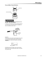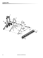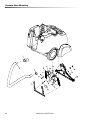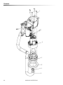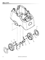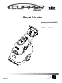
1
Carpet Extractor
Operating Instructions (ENG)
MODELS: 10080480
Read these instructions before using the machine.
86302100-BJ
03/03/15
Machine Data Label
Overview
This carpet extractor is an electrical powered, portable carpet extractor intended for commercial use. The
appliance sprays a cleaning solution onto the carpet agitates the wet carpet, and then extracts the soiled solution
back into the unit's recovery tank. The appliance is fitted with and a hand tool for cleaning upholstery and stairs.
Warranty Registration
Thank you for purchasing a Windsor product. Warranty registration is quick and easy.
Your registration will allow us to serve you better over the lifetime of the product.
To register you product go to :
www.windsorind.com/WarrantyRegistration.aspx
For customer assistance:
1-800-444-7654
2
86302100 CLIPPER DUO
Table of Contents
Machine Data Label . . . . . . . . . . . . . . . . . . . . . . . . . . 2
Overview . . . . . . . . . . . . . . . . . . . . . . . . . . . . . . . . . . 2
Table of Contents . . . . . . . . . . . . . . . . . . . . . . . . . . . 3
How To Use This Manual . . . . . . . . . . . . . . . . . . . . . 4
Safety
IMPORTANT SAFETY INSTRUCTIONS . . . . . . . . . 5
HAZARD INTENSITY LEVEL . . . . . . . . . . . . . . . . . . 7
GROUNDING INSTRUCTIONS . . . . . . . . . . . . . . . . 9
SAFETY LABEL LOCATION . . . . . . . . . . . . . . . . . 10
Operations
Technical Specifications . . . . . . . . . . . . . . . . . . . . . 11
How This Machine Works . . . . . . . . . . . . . . . . . . . . 13
Components . . . . . . . . . . . . . . . . . . . . . . . . . . . . . . 14
Controls. . . . . . . . . . . . . . . . . . . . . . . . . . . . . . . . . . 15
Filling The Solution Tank . . . . . . . . . . . . . . . . . . . . 16
Pre Run Setup . . . . . . . . . . . . . . . . . . . . . . . . . . . . 17
Operating The Machine . . . . . . . . . . . . . . . . . . . . . 19
Using The Hand Tool . . . . . . . . . . . . . . . . . . . . . . . 22
Parts
Brush Deck . . . . . . . . . . . . . . . . . . . . . . . . . . . . . .
Brush Deck Motor . . . . . . . . . . . . . . . . . . . . . . . . .
Brush Deck Mounting . . . . . . . . . . . . . . . . . . . . . .
Control Panel . . . . . . . . . . . . . . . . . . . . . . . . . . . .
Decal . . . . . . . . . . . . . . . . . . . . . . . . . . . . . . . . . . .
Hand Tool . . . . . . . . . . . . . . . . . . . . . . . . . . . . . . .
Handle. . . . . . . . . . . . . . . . . . . . . . . . . . . . . . . . . .
Handle Bracket . . . . . . . . . . . . . . . . . . . . . . . . . . .
Handle Mounting . . . . . . . . . . . . . . . . . . . . . . . . . .
Handle Release Lever . . . . . . . . . . . . . . . . . . . . .
Recovery Tank . . . . . . . . . . . . . . . . . . . . . . . . . . .
Solution - From Serial Number (*6). . . . . . . . . . . .
Solution - Prior to Serial Number (*6) . . . . . . . . . .
Solution - From Serial Number (*6). . . . . . . . . . . .
Solution - Prior to Serial number (*6) . . . . . . . . . .
Solution Tank . . . . . . . . . . . . . . . . . . . . . . . . . . . .
Vacuum Shoe . . . . . . . . . . . . . . . . . . . . . . . . . . . .
Vacuum Shoe Mounting . . . . . . . . . . . . . . . . . . . .
Vacuum . . . . . . . . . . . . . . . . . . . . . . . . . . . . . . . . .
Wheel & Axle . . . . . . . . . . . . . . . . . . . . . . . . . . . .
Wiring Diagram . . . . . . . . . . . . . . . . . . . . . . . . . . .
Suggested Spare Parts . . . . . . . . . . . . . . . . . . . . .
Serial Numbers . . . . . . . . . . . . . . . . . . . . . . . . . . .
32
34
36
38
40
42
44
46
48
50
52
54
56
58
60
62
64
66
68
70
72
74
75
Maintenance
Service Schedule . . . . . . . . . . . . . . . . . . . . . . . . . . 23
Components . . . . . . . . . . . . . . . . . . . . . . . . . . . . . . 24
. . . . . . . . . . . . . . . . . . . . . . . . . . . . . . . . . . . . . . . . 24
Periodic Maintenance . . . . . . . . . . . . . . . . . . . . . . 25
Circuit Protection. . . . . . . . . . . . . . . . . . . . . . . . . . . 26
Scrub Deck . . . . . . . . . . . . . . . . . . . . . . . . . . . . . . . 27
Scrub Brush Replacement . . . . . . . . . . . . . . . . . . . 28
Vacuum Motor Carbon Brushes . . . . . . . . . . . . . . . 29
Troubleshooting . . . . . . . . . . . . . . . . . . . . . . . . . . . 30
86302100 CLIPPER DUO
3
How To Use This Manual
The SAFETY section contains important information
regarding hazardous or unsafe practices of the
machine. Levels of hazards are identified that could
result in product damage, personal injury, or severe
injury resulting in death.
This manual contains the following sections:
•
•
•
•
•
HOW TO USE THIS MANUAL
SAFETY
OPERATIONS
MAINTENANCE
PARTS LIST
The OPERATIONS section is to familiarize the operator
with the operation and function of the machine.
The HOW TO USE THIS MANUAL section will tell you
how to find important information for ordering correct
repair parts.
Parts may be ordered from authorized dealers. When
placing an order for parts, the machine model and
machine serial number are important. Refer to the
MACHINE DATA box which is filled out during the
installation of your machine. The MACHINE DATA box
is located on the inside of the front cover of this manual.
The MAINTENANCE section contains preventive maintenance to keep the machine and its components in
good working condition. They are listed in this general
order:
•
•
•
Periodic
Daily/Regular
Troubleshooting
The PARTS LIST section contains assembled parts
illustrations and corresponding parts list. The parts lists
include a number of columns of information:
•
The model and serial number of your machine are
located where shown.
REF - column refers to the reference number on
the parts illustration.
• PART NO. - column lists the part number for the
part.
• PRV NO. - Reference number.
• QTY - column lists the quantity of the part used
in that area of the machine.
• DESCRIPTION - column is a brief description of
the part.
• SERIAL NO. FROM - If this column has an (*)
and a Reference number, see the SERIAL
NUMBERS page in the back of your manual. If
column has two asterisk (**), call manufacturer
for serial number. The serial number indicates
the first machine the part number is applicable
to. The main illustration shows the most current
design of the machine. When a boxed illustration is shown, it displays the older design.
• NOTES - column for information not noted by
the other columns.
NOTE: If a service or option kit is installed on your
machine, be sure to keep the KIT INSTRUCTIONS
which came with the kit. It contains replacement parts
numbers needed for ordering future parts.
NOTE: The manual part number is located on the
lower left corner of the front cover.
4
86302100 CLIPPER DUO
Safety
IMPORTANT SAFETY INSTRUCTIONS
When using an electrical appliance, basic precaution
must always be followed, including the following:
READ ALL INSTRUCTIONS BEFORE USING THIS MACHINE.
This machine is for commercial use.
To reduce the risk of fire, electric shock, or injury:
Connect to a properly grounded outlet. See Grounding Instructions.
Do not leave the machine unattended. Unplug machine from outlet when not in use and before maintenance or
service.
Use only indoors. Do not use outdoors or expose to rain.
Do not allow machine to be used as a toy. Close attention is necessary when used by or near children.
Use only as described in this manual. Use only manufacturer's recommended components and attachments.
Do not use damaged electrical cord or plug. Follow all instructions in this manual concerning grounding the
machine. If the machine is not working properly, has been dropped, damaged, left outdoors, or dropped into water,
return it to an authorized service center.
Do not pull or carry machine by electrical cord, use as a handle, close a door on cord, or pull cord around sharp
edges or corners.
Do not run machine over cord. Keep cord away from heated surfaces.
Do not unplug machine by pulling on cord. To unplug, grasp the electrical plug, not the electrical cord.
Do not handle the electrical plug or machine with wet hands.
Do not operate the machine with any openings blocked. Keep openings free of debris that may reduce airflow.
This machine is intended for cleaning carpet only.
Do not vacuum anything that is burning or smoking, such as cigarettes, matches, or hot ashes.
This machine is not suitable for picking up health endangering dust.
Turn off all controls before unplugging.
Machine can cause a fire when operating near flammable vapors or materials. Do not operate this machine near
flammable fluids, dust or vapors.
This machine is suitable for commercial use, for example in hotels, schools, hospitals, factories, shops and offices
for more than normal housekeeping purposes.
Maintenance and repairs must be done by qualified personnel.
If foam or liquid comes out of machine, switch off immediately.
SAVE THESE INSTRUCTIONS
86302100 CLIPPER DUO
5
Safety
IMPORTANTES MESURES DE SÉCURITÉ
L'utilisation d'un appareil électrique demande
certaines précautions:
LIRE TOUTES LES INSTRUCTIONS AVANT DE FAIRE FONCTIONNER (CET APPAREIL).
Pour réduire les risques d'incendie, de choc
électrique ou de blessure:
Cet appareil ne doit être connecter qu a des prises ayant une sortie de terre.
Ne pas laisser l'appareil sans surveillance lorsqu'il est branché. Débrancher lorsque l'appareil n'est pas utilisé et
avant l'entretien.
Pour reduire les risques de choc electrique, ne pas utiliser à l exterieur et ne pas aspirer de matières humides.
Ne pas permettre aux enfants de jouer avec l'appareil. Une attention particulière est nécessaire lorsque l'appareil
est utilisé par des enfants ou à proximité de ces derniers.
N'utiliser que conformément à cette notice avec les accessoires recommandés par le fabricant.
Ne pas utiliser si le cordon ou la fiche est endommagé. Retourner l'appareil à un atelier de réparation s'il ne fonctionne pas bien, s'il est tombé ou s'il a été endommagé, oublié à l'extérieur ou immergé.
Ne pas tirer soulever ou traîner l'appareil par le cordon. Ne pas utiliser le cordon comme une poignée, le coincer
dans l'embrasure d'unée porte ou l'appuyer contre des arêtes vives ou des coins. Ne pas faire rouler l'appareil sur
le cordon.
Garder le cordon à l'écart des surfaces chaudes.
Ne pas débrancher en tirant sur le cordon. Tirer plutôt la fiche.
Ne pas toucher la fiche ou l'appareil lorsque vos mains sont humides.
N'insérer aucun objet dans les ouvertures. Ne pas utiliser l'appareil lorsqu'une ouverture est bloquée. S'assure
que de la poussière, de la peluche, des cheveux ou d'autres matières ne réduisent pas le débit d'air.
Cette machine est destinée pour nettoyer tapis seulement.
Ne pas aspirer de matiéres en combustion ou qui dégagent de la fumée, comme des cigarettes, des allumettes ou
des cendres chaudes.
Cette machine n'est pas adaptée au ramassage de poussières dangereuses.
Mettre toutes les commandes à la position ARRÊT avant de débrancher l'appareil.
Ne pas aspirer des liquides inflammables ou combustibles, comme de l'essence, et ne pas faire fonctionner dans
des endroits où peuvent se trouver de tels liquides.
Cette machine est destinée à un usage commercial. Elle est recommandée davantage pour les domaines hôtelier,
scolaire, hospitalier, industriel ou pour les bureaux, les chaînes de magasin, que pour un usage domestique
normal.
L'entretien et les réparations de la machine doivent être effectuées par un personnel qualifié.
Si de la mousse ou du liquide sort de la machine, la mettre hors tension immédiatement.
CONSERVER CES INSTRUCTIONS
6
86302100 CLIPPER DUO
Safety
The following symbols are used throughout this guide as indicated in their descriptions:
HAZARD INTENSITY LEVEL
There are three levels of hazard intensity identified by signal words -WARNING and CAUTION and FOR SAFETY.
The level of hazard intensity is determined by the following definitions:
WARNING - Hazards or unsafe practices which COULD result in severe personal injury or death.
CAUTION - Hazards or unsafe practices which could result in minor personal injury or product or property damage.
FOR SAFETY: To Identify actions which must be followed for safe operation of equipment.
Report machine damage or faulty operation immediately. Do not use the machine if it is not in proper operating
condition. Following is information that signals some potentially dangerous conditions to the operator or the equipment. Read this information carefully. Know when these conditions can exist. Locate all safety devices on the
machine. Please take the necessary steps to train the machine operating personnel.
FOR SAFETY:
DO NOT OPERATE MACHINE:
Unless Trained and Authorized.
Unless Operation Guide is Read and understood.
In Flammable or Explosive areas.
In areas with possible falling objects
WHEN SERVICING MACHINE:
Avoid moving parts. Do not wear loose clothing; jackets, shirts, or sleeves when working on the machine. Use
Windsor approved replacement parts.
86302100 CLIPPER DUO
7
Safety
Les symboles ci-dessous sont utilisés à travers ce manuel comme illustré dans leurs descriptions :
DEGRÉS DE RISQUES EN CAS DE DANGER
Il existe trois degrés de risques identifiés par les termes signalétiques -AVERTISSEMENT et ATTENTION et
POUR VOTRE SÉCURITÉ. Le degré de risque est défini de la manière suivante :
AVERTISSEMENT - Dangers ou méthodes dangereuses qui POURRAIENT provoquer de graves blessures ou
entraîner la mort.
ATTENTION - Dangers ou méthodes dangereuses qui pourraient provoquer des blessures légères ou une détérioration du produit ou des biens immobiliers.
POUR VOTRE SÉCURITÉ : ce signe permet d'identifier les mesures de précaution à prendre pour assurer
un bon fonctionnement du matériel.
Rendre compte immédiatement d'une défaillance ou d'une détérioration de la machine. Ne pas utiliser la machine
si celle-ci ne fonctionne pas correctement. Lire soigneusement les informations ci-dessous signalant certains
dangers potentiels pour l'opérateur de la machine. L'opérateur doit être absolument au courant de ces dangers
potentiels. Localiser tous les dispositifs de sécurité sur la machine. Il est conseillé de prendre les mesures nécessaires pour former le personnel opérateur.
POUR VOTRE SÉCURITÉ :
NE PAS MANOEUVRER LA MACHINE :
Lorsqu'on n'est pas expérimenté ou qualifié.
Lorsque le guide d'utilisation n'est pas été lu ou compris.
Dans des zones inflammables ou explosives.
Dans des zones où des objets peuvent tomber.
LORS DE L'ENTRETIEN DE LA MACHINE :
Éviter les parties amovibles. Ne pas porter de vêtements amples, tels que des vestes, des chemises ou des
vêtements avec manches lors de l'utilisation de la machine. Utiliser les pièces détachées Windsor homologuées.
8
86302100 CLIPPER DUO
Safety
GROUNDING INSTRUCTIONS
120 VOLT MODELS:
THIS PRODUCT IS FOR COMMERCIAL
USE ONLY.
This appliance is for use on a nominal 120-volt circuit,
and has a grounded plug that looks like the plug in "Fig.
A". A temporary adaptor that looks like the adaptor in
"Fig. C" may be used to connect this plug to a 2-pole
receptacle as shown in "Fig. B", if a properly grounded
outlet is not available. The temporary adaptor should
be used only until a properly grounded outlet (Fig. A)
can be installed by a qualified electrician. The green
colored rigid ear, lug, or wire extending from the
adaptor must be connected to a permanent ground
such as a properly grounded outlet box cover.
Whenever the adaptor is used, it must be held in place
by a metal screw.
ELECTRICAL:
In the USA this machine operates on a standard 15
amp 120V, 60 hz, A.C. power circuit. The amp, hertz,
and voltage are listed on the data label found on each
machine. Using voltages above or below those
indicated on the data label will cause serious damage
to the motors.
EXTENSION CORDS:
If an extension cord is used, the wire size must be at
least one size larger than the power cord on the
machine, and must be limited to 50 feet (15.5m) in
length.
GROUNDING INSTRUCTIONS:
This appliance must be grounded. If it should malfunction or break down, grounding provides a path of least
resistance for electric current to reduce the risk of
electric shock. This appliance is equipped with a cord
having an equipment-grounding conductor and
grounding plug. The plug must be inserted into an
appropriate outlet that is properly installed and
grounded in accordance with all local codes and ordinances.
Improper connection of the equipment-grounding
conductor can result in a risk of electric shock.
Check with a qualified electrician or service person
if you are in doubt as to whether the outlet is
properly grounded. Do not modify the plug
provided with the appliance - if it will not fit the
outlet, have a proper outlet installed by a qualified
electrician.
Le raccordement incorrect du conducteur de terre
d'équipement peut entraîner des risques d'électrocution. Vérifiez auprès d'un électricien qualifié ou
d'un responsable de l'entretien si vous avez
quelque doute que ce soit quant au raccordement à
la terre de votre prise murale. Ne modifiez pas la
fiche fournie avec l'appareil : si elle ne correspond
pas à la prise murale, faites installer une prise
adéquate par un électricien qualifié.
GROUNDED
OUTLET BOX
GROUNDED
OUTLET
ADAPTER
TAB FOR
GROUNDING SCREW
METAL SCREW
GROUNDING
PIN
(A)
(B)
86302100 CLIPPER DUO
(C)
9
Safety
SAFETY LABEL LOCATION
NOTE: These drawings indicate the location of safety labels on the machine. If at any time the labels become illegible, promptly replace them.
Les ÉTIQUETTES D'AVERTISSEMENT suivantes se trouvent sur votre unité de nettoyage. Ces étiquettes
signalent les avertissements et mises en garde importantes qui doivent être suivis en tout temps. Le non respect
des avertissements et mises en garde pourrait entraîner des dommages matériels, des blessures graves ou même
la mort. Suivez attentivement ces instructions ! NE PAS retirer ces étiquettes. REMARQUE : Si, à tout moment, les
étiquettes deviennent illisibles, remplacez-les rapidement.
WARNING LABEL
PART NUMBER 86242230
PRV NO 500009
WARNING LABEL
EXPLOSION FRENCH
PART NUMBER 86310500
10
86302100 CLIPPER DUO
Operations
Technical Specifications
ITEM
Construction
Vacuum Motor
Solution Pump
Brush Motor
Brushes
Cleaning Path
Flow Rate
Solution Spray
Solution Tanks
Recovery Tank
Vacuum Shoe
Wheels
Power Cable
Weight
DIMENSION/CAPACITY
Steel chassis with rotationally molded polyethylene tanks
Three stage, bypass, 1.5 hp (1,119 watts), 100 cfm (2.8m³/min), 120" (3050 mm)
waterlift
100 psi (7 bar) - Restorative
50 psi (3.5 bar) - Interim
1/2 hp (604 watts) AC with circuit breaker protection
2 x 16" (406 mm), ABS core, Perform Alert™ bristle spiral pattern
16" (40.6 cm)
Interim - 0.09 gpm ( 0.37 lpm)
Restorative - 1.0 gpm (37.8 lpm)
Interim - One quick-disconnect jet
Restorative - One quick-disconnect jet
10 gallons ( 37.8 l)
10 gallons (37.8 l)
18" (458 mm) wide, cast aluminum
10" (254 mm) non-marking rubber
50' (15 m) detachable
166 lbs (75.3 kg) with cord
86302100 CLIPPER DUO
11
Operations
ITEM
Height
Length
Width
Width of scrub path
MEASURE
43 inches (1092 mm)
40.5 inches (1029 mm)
22 inches (559 mm)
16 inches (406 mm)
HEIGHT
LENGTH
WIDTH
Special Notes:
This appliance is not intended for use by persons
(including children) with reduced physical, sensory or
mental capabilities, or lack of experience and knowledge, unless they have been given supervision or
instruction concerning use of the appliance by a person
responsible for their safety. Children should be supervised to ensure that they do not play with appliance.
The sound pressure level at the operator's ear was
measured to be 73.7 dBA. This was a nearfield, broadband measurement taken in a typical industrial environment on a tile floor. This appliance contains no
possible source of impact noise. The instantaneous
sound pressure level is below 63 Pa.
The weighted root mean square acceleration at the
operator's arms was measured to be below 2.5m/s2 .
This was a tri-axial, third-octave-band measurement
made during normal operation on a composite tile floor.
The measurement and related calculations were made
in accordance with ISO 5349-1.
12
86302100 CLIPPER DUO
Operations
How This Machine Works
This carpet extractor is an electrical powered, portable
carpet extractor intended for commercial use. The
appliance sprays a cleaning solution onto the carpet
agitates the wet carpet, and then extracts the soiled
solution back into the unit's recovery tank. The
appliance is fitted with and a hand tool for cleaning
upholstery and stairs.
The machine is designed to maintain your carpet using
the Encapsulating Interim Carpet Cleaning Process.
By using the Interim Carpet Maintainer in conjunction
with Windsor Red Carpet Encapsulating Interim
Cleaning (W450-4) or Encapsulating Interim Cleaning
with Carpet Protection (W455-4) chemical solution, you
can perform a regular light cleaning and grooming of
your carpet very quickly, and have the carpet dry and
ready for traffic within 30 minutes.
The machine is also designed to restore your carpet
using carpet extraction chemicals. The machine is
designed to apply cleaning solution onto carpeted floor,
scrub the carpet with two counter-rotating brushes, and
then vacuum the soiled water back into the recovery
tank.
The machine's primary systems are the solution
system, scrub system, recovery system and operator
control system.
The function of the solution system is to store mixed
solution and deliver solution to the appropriate spray
jet. The solution system consists of the solution tank,
strainer, extraction pump and interim pump, solenoid
valve, spray jets, accessory hand tool, and controls.
The solution tank stores solution until it is delivered
through the strainer to the appropriate pump. The
solenoid valve allows flow from the extraction pump to
the extraction nozzle or stops flow at the extraction
nozzle so that the accessory hand tool can be used.
The interim pump provides flow directly to the interim
nozzle. The strainer protects the pump from debris.
The solution pumps control the cleaning solution flow.
The function of the scrub system is to scrub the carpet,
mix the cleaning solution with the soil and lift and groom
the carpet pile. The scrub system consists of two cylindrical brushes, motor, and controls. The brushes scrub
the carpet as the motor drives the brushes. The
counter-rotating action of the brushes grooms the
carpet pile.
The function of the recovery system is to vacuum the
soiled water back into the recovery tank. The recovery
system consists of the vacuum shoe, vacuum motor,
float ball filter, recovery tank and controls. The vacuum
shoe extracts the dirty solution from the carpet as the
machine moves forward. The vacuum motor provides
suction to draw the dirty solution off the floor and into
the recovery tank. The float ball filter protects the
vacuum fan from debris and foam. The recovery tank
stores the dirty solution.
The function of the operator control system is to allow
the operator to select the desired function to perform.
This appliance is not suitable for picking up hazardous
dust.
Cet appareil n'est pas conçu pour aspirer des poussières dangereuses.
86302100 CLIPPER DUO
13
Operations
Components
1
2
3
4
8
6
7
5
9
1. Control Panel
6. Solution Fill Cover
2. Recovery Dome
7. Solution Drain Hose
3. Recovery Drain Hose
8. Solution Tank
4. Recovery Tank
9. Vacuum Shoe
5. Scrub Deck
14
86302100 CLIPPER DUO
Operations
Controls
3
5
1
2
4
6
7
1. Hand Tool Switch
5. Continuous Spray
2. Main Switch
6. Intermittent Spray
3. Light Cleaning
7. Intermittent Spray Buttons
4. Deep Cleaning
86302100 CLIPPER DUO
15
Operations
Filling The Solution Tank
REMOVE SOLUTION
FILL COVER
Do not put defoamer, solvents, spotter or
prespray chemicals in the solution tank.
Do not allow water to spill into vacuum motor inlet.
Dry spills from top of solution tank.
Use only the suitable chemicals listed below. Using
incompatible chemicals will damage the machine.
Damages of this type are not covered under warranty.
Carefully read ingredients on manufacturer's label
before using any product in this machine.
CHEMICALS
Suitable Chemicals
Alkalis
Detergents
Hydroxides
Soaps
Vinegar
Non-Compatible Chemicals
Aldehydes
Aromatic Hydrocarbons
SP Butyls
Carbon Tetrachloride Clorox*
Chlorinated Bleaches
Chlorinated Hydrocarbons
Lysol*
Methyl Ethel Ketone (MEK)
Perchorethylene (perc)
Phenolics
Trichlorethylene
D-Limonene
STEP 1
ADD WATER
10 Gal.
(38 Lt)
140°F (60°C)
OR
STEP 2
ADD CLEANING
CHEMICAL PER
CHEMICAL LABELING
FILL LINE
STEP 3
REPLACE SOLUTION
FILL COVER
STEP 4
16
86302100 CLIPPER DUO
Operations
Pre Run Setup
Remove electrical cord and literature from recovery
tank. Fill solution tank (see filling instructions).
STEP 1
Plug cord into grounded outlet. NOTE: Be sure dome
is seated on recovery tank, and float shut-off is installed
correctly.
STEP 2
Switch the cleaning mode switch to the desired
process.
A for the encapsulating Interim Carpet Cleaning
Process.
B for Deep Extraction.
STEP 3
Adjust handle to comfortable operating position. Tip
machine back by main handle to move to starting point.
STEP 4
86302100 CLIPPER DUO
17
Operations
Pre Run Setup
Lower machine to floor.
STEP 5
Select continuous setting to start solution spray or
select intermittent setting to enable use of trigger
switches to start solution spray.
The intermittent setting requires the operator to hold
any one of the three trigger switches in the "on" position
with the fingers, and is typically used in small areas
where short cleaning passes are made.
STEP 6
The continuous setting allows the operator to set the
switch in the "on" position with one touch, and is
typically used in large areas where long cleaning
passes are made.
Place main switch in machine cleaning mode to start
cleaning process.
18
86302100 CLIPPER DUO
Operations
Operating The Machine
2
1
1. This machine can be operated in either direction.
For smaller areas operate the machine by pulling
rearward.
2. For larger unobstructed areas, flip the handle and
use the machine's brush assisted propelling
motion.
STEP 1
Start at wall closest to power outlet. For small areas,
pull straight back without pushing down on handle.
STEP 2
1 ft.
(30 cm)
Release intermittent trigger switches or turn off continuous setting on solution switch approximately 1 foot
before ending cleaning pass.
STEP 3
Push down on handle to raise vacuum shoe and brush
before moving to the next cleaning pass. Overlap
brush contact area approximately 1 inch.
1 in.
(25mm)
STEP 4
86302100 CLIPPER DUO
19
Operations
Operating The Machine
Start at wall closest to power outlet. For large areas flip
handle and operate machine in parallel passes, overlapping brush path. Clean perimeter last.
ALTERNATE CLEANING PATH
VACUUM INTAKE
SOLUTION INTAKE
STEP 5
During operation, observe the following: This machine
is equipped with clear dome to facilitate operator
viewing of dirty solution and vacuum air flow.
During operation, observe the vacuum intake. Large
amounts of water or foam entering the vacuum system
can damage the vacuum motor. If you notice either
condition, shut down the machine immediately. Empty
recovery tank and/or add defoamer to recovery tank.
Use right side of machine for cleaning against walls.
STEP 6
CENTER
OFF
POSITION
SHUT
DOWN
After cleaning, turn off all controls, and carefully unplug
machine.
20
86302100 CLIPPER DUO
Operations
To speed drying, use a Windblower™ fan.
Empty recovery tank by releasing recovery drain hose.
Use a hose with cold water to clean out the recovery
tank. Also drain solution tank after each use.
RECOVERY
DRAIN HOSE
SOLUTION
DRAIN HOSE
STEP 7
86302100 CLIPPER DUO
21
Operations
Using The Hand Tool
Use only acceptable accessory tools. See Optional
Accessories section.
To connect solution hose pull back collar and insert
over machine mounted fitting, then release collar to
lock into place. Solution connection can remain
connected at all times.
Disconnect vacuum hose and connect the hand tool to
hand tool connection as shown.
HAND TOOL
CONNECTION
SOLUTION QUICK
DISCONNECT
HAND TOOL POSITION
Select hand tool switch.
Squeeze handle on accessory tool to begin cleaning.
22
86302100 CLIPPER DUO
Maintenance
Service Schedule
MAINTENANCE
Check machine for cord damage
Check recovery dome and gasket for damage and cleanliness
Check brushes - should be clean with no lint or strings attached
Remove bearing cap from end of brush. Clean bearing and cap.
Inspect vac shoe for blockage; remove fibers with coat hanger, etc.
Check hoses for wear, blockages, or damage
Check handles, switches, and knobs for damage
Run one gallon of water through solution system
Clean out recovery tank, clean float screen and check float valve to
make sure it moves freely
Clean out solution
Clean outside of all tanks and check for damage
Run vac motor for at least one minute to allow motor to dry
Store with dome off tank to allow the tank to dry
Check all bearings for noise
Check all gaskets for wear and leakage
Check pump pressure; observe spray pattern and check with gauge
if necessary
Check and clean solution screen
Check brush for wear; ensure bristles are not damaged
Check condition of vac shoe and frame for damage
Check overall performance of machine
Check vac motor carbon brushes
Check belts for wear and replace as necessary
Check cables for fraying
86302100 CLIPPER DUO
DAILY
*
*
*
*
*
*
*
*
WEEKLY
QUARTERLY
*
*
*
*
*
*
*
*
*
*
*
*
*
*
*
23
Maintenance
Components
6
2
4
1
LEFT
3A
BOTTOM
3B
1.
Vacuum Motor
4. Interim Solution Pump
2.
Solution Strainer (Inside Tank Fitting)
5. Main Solution Pump
3A. Spray Jet-Extraction
6. Float Shut-off
3B. Spray Jet-Interim
24
86302100 CLIPPER DUO
5
RIGHT
Maintenance
Periodic Maintenance
Twice a month, flush a white vinegar solution (One
quart vinegar to two gallons of water) or anti-browning
solution (mixed as directed) through the extractor. This
will prevent build-up of alkaline residue in the system. If
spray jets become clogged, remove the spray tips,
wash them thoroughly, and blow-dry.
3. After each use, rinse tank with fresh water. Periodically inspect the recovery tank and decontaminate
if necessary, using a Hospital Grade Virucide or a
1-10 bleach to water solution. Waste water should
be disposed of properly.
NOTE: Do not use pins, wire, etc. to clean nozzles as
this could destroy spray pattern.
5. Check spray jets for full spray pattern.
Periodically inspect all hoses, electrical cables and
connections on your machine. Frayed or cracked hoses
should be repaired or replaced to eliminate vacuum or
solution pressure loss. If the cable insulation is broken
or frayed, repair or replace it immediately. Don't take
chances with electrical fire or shock.
Daily / Regular Maintenance
4. Check for and remove any lint or debris around vac
shoe.
6. Remove lint and dirt build-up from brush and
housing.
7. Check float and shut-off screen and clean as
necessary.
Vacuum Shoe and Hose
NOTE: Vacuum Shoe and hose flush should be done
daily after use. Place machine over drainage area
before beginning.
1. Remove vacuum hose from dome.
NOTE: Before making any adjustments or repairs to the
machine, disconnect the power cord from electrical
source
1. Empty unused cleaning solution from the solution
tank.
2. Insert water hose into vacuum hose.
3. With water pressure on high, rinse out hose and
vacuum shoe. Water should flow freely from
vacuum shoe.
2. Flush pumping system with 4 or 7 liters of clean,
hot water.
86302100 CLIPPER DUO
Vacuum Hose
25
Maintenance
Circuit Protection
CIRCUIT BREAKERS
Circuit Breakers
Circuit breakers interrupt the flow of power in the event
of an electrical overload. When a circuit breaker is
tripped, reset it by pressing the exposed button. If a
circuit breaker continues to trip. The cause should be
found and corrected.
15 Amp. Protects the vacuum motor.
8 Amp. Protects the brush motor.
26
86302100 CLIPPER DUO
Maintenance
Scrub Deck
1
3
4
2
1. Scrub Brush Motor
2. Scrub Brushes
3. Retaining Clip
4. Brush Installation Decal
86302100 CLIPPER DUO
27
Maintenance
Scrub Head
Scrub Brush Replacement
The dual cylindrical scrub head is designed to scrub
chemical into the carpet. The two counter rotating
brushes raise the pile of the carpet, giving it a lush
groomed appearance.
The rear brush is the stiffer brush and is intended to
scrub deeper and help propel the machine. It can be
identified by its black color.
The front brush is the softer brush and is intended to lift
and groom the carpet pile. It can be identified by the
white bristles.
NOTE: See brush placement decal on brush deck.
(Black brush to rear of machine and white brush to
front of machine).
Only use the brushes provided with the appliance
or those specified in the instructions manual. The
use of other brushes may impair safety.
Maintenance
Scrub brushes should be replaced as a set when bristle
length wears to height of yellow Perform AlertTM
bristles.
Scrub Brush Removal
1. Disconnect all power and unplug machine.
1. Lift the drive side of the brush and push it onto
drive hub until a positive stop is felt. The brush
cannot be installed until the brush is fully seated on
the drive hub.
2. Tip the machine back.
2. Pull out on the bottom of the retaining clip.
3. Pull out on the bottom of the retaining clip.
3. Line up the end cap with the flats to each side.
4. The brush assembly and end cap should drop
down. Then pull the brush down far enough to
clear the bottom of the housing.
4. Slide brush up into the retaining clip until it clicks in
place.
The scrub brushes are removed from the right side of
the machine.
5. Pull brush out with a rocking motion to free brush
from drive hub.
Only qualified maintenance personnel are to
perform the following repairs
Bearing Cleaning
1. Remove bearing cap from end of brush.
2. Clean cap and bearings.
Seul le personnel d'entretien qualifié peut effectuer
des réparations.
Vacuum Motor Replacement
1. Turn off all switches and unplug machine.
2. Remove recovery tank.
3. Remove handle mounting assembly and set aside.
4. Disconnect and remove the solution/vacuum frame
assembly through the top of the machine.
5. Remove the vacuum motor to service brushes.
6. Reverse process to install vacuum motor.
28
86302100 CLIPPER DUO
Maintenance
Vacuum Motor Carbon Brushes
End Cap
Carbon Brushes
The green ground wire must be attached for safe
operation. See wiring diagram.
If armature commutator is grooved, extremely pitted or
not concentric, the motor will need to be replaced or
sent to a qualified service center.
Important:
These brushes wear quicker as the length shortens due
to increased heat. Spring inside brush housing will
damage motor if brushes are allowed to wear away
completely.
3 [9.5mm]
8
Periodically check the length of the carbon brushes.
Replace both carbon brushes when either is less than
3/8" (9.5mm) long.
86302100 CLIPPER DUO
29
Maintenance
Troubleshooting
PROBLEM
No Power, Nothing
Runs
Vacuum Motor Will Not
Run
Vacuum Motor Runs
But Suction Is Poor
CAUSE
Is the cord plugged in.
Plug in cord.
Circuit breaker tripped in building.
Faulty switch.
Faulty power cord or pigtail.
Reset breaker.
Call for service.
Call for service.
Vacuum circuit breaker tripped.
Reset breaker.
Faulty main vacuum switch.
Loose wiring.
Faulty vac motor.
Call for service.
Call for service.
Call for service.
Debris lodged in vac shoe.
Remove debris from vac shoe.
Dome gasket defective or missing.
Vacuum hose cracked or hose cuff loose.
Recovery tank full / float ball stuck in the
up position.
Replace as necessary.
Replace or repair as necessary.
Turn off vac motor. Drain and rinse
recovery tank.
Turn to continuous or use buttons on
handle
Clean using a vinegar /water solution or
replace.
Drain solution tank and clean solution
filter.
Call for service.
Turn main switch to machine mode.
Reset circuit breaker.
Replace as necessary.
Call for service.
Poor Or No Water Flow Pump switch in intermittent position.
(Carpet Is Streaky)
Jets clogged or missing.
Solution filter clogged.
Brush Does Not Spin
30
SOLUTION
Faulty solenoid.
Main switch off or in hand tool mode.
Brush circuit breaker tripped.
Brush belt broken.
Faulty brush motor.
86302100 CLIPPER DUO
Parts
PARTS
86302100 CLIPPER DUO
31
Brush Deck
32
86302100 CLIPPER DUO
Brush Deck
REF
PART NO.
QTY
1
2
3
4
5
6
7
8
9
10
11
12
13A
13B
14
15
16
17
18
19
20
21
22
23
24
25
26
27
28
29
86223780
86224170
86373070
86012810
86223520
86223310
86215250
86224660
86173330
86014990
86215870
86012780
86216050
86295520
86223490
86224130
86343870
86294070
86012790
86172970
86222870
86217780
86219390
86173350
86172980
86224630
86277130
86215230
86294060
86350490
8
2
2
1
3
1
1
1
1
9
1
2
1
1
2
1
1
1
2
3
1
1
1
4
2
2
7
1
1
3
DESCRIPTION
SCR, M4X8, SET, ISO4029,CP,BLK
SHAFT, 6.2MM BRUSH DRIVE
ASM, BRUSH END, NON-DRIVE
SHAFT, ASM, DRIVE 16"
RING, 28MM INT SNAP PHOSPHATE
PULLEY, 5MM HTD, 18T, 12.7 ID
BELT, 2S 5MM HTD, 15W, 128T
SPRING, TENSIONER
WASHER, M5 FLAT, ISO7093 SS
SCR, M5X20, SHCS ISO4762, SS
BRKT, TENSIONER ARM
PULLEY ASM, 5MM HTD 22T
BRUSH, EXTRACTOR 16"
BRUSH, EXTRACTOR 16" NATURAL
RING, 10MM EXT SNAP, DIN 471
SHAFT, TENSIONER
HOUSING ASM, BRUSH DRIVE
PULLEY, 36T 5MM HTD
SHAFT ASM, BRUSH DRIVE
SCR, M5X12, PHLP FHMS, ISO7046, SS
PLATE, BRUSH DRIVE COVER
EXTRUSION, DUAL BRUSH 16"
HOUSING, BRUSH CLIP
WASHER, M5, FLAT, ISO7089,SS
SCR, KA50X10, PT OHS, WN14112, PLTD
SPRING, BRUSH CLIP
SCR, 5/16-18 X 1.00 CARRIAGE SS
BEARING, BRONZE FLANGED
PULLEY, 30T 5MM HTD
PLUG, HOLE, 5MM DIA X 12 MM L
SERIAL NO.
FROM
NOTES
*(5)
**
*SEE SERIAL NUMBER PAGE.
**CALL MANUFACTURER FOR SERIAL NUMBER
86302100 CLIPPER DUO
33
Brush Deck Motor
34
86302100 CLIPPER DUO
Brush Deck Motor
DESCRIPTION
SERIAL NO.
FROM
REF
PART NO.
QTY
1
2
3
4
5
6
86273750
86173340
86010630
86215880
86294490
86222290
6
6
6
2
1
3
SCR, 1/4-20 X 5/8 HHCS SS
WASHER, SPLIT LOCK, 1/4 SS
WASHER, 1/4 ID X 5/8 OD SS
BRKT, MOTOR MOUNT
BRUSH MOTOR ASM 115V
NUT, 5/16-18 HEX NYLOCK SS
7
86346070
2
COUPLER, 2-JAW, 35MM
*(2)
8
9
10
11
12
13
14
15
16
17
86234600
86172960
86225790
86005640
86002390
86198450
86276820
86216750
86332820
86332830
1
2
3
1
1
1
1
1
-
COUPLER, SPIDER
SCR, SET, M6X8, SH, ISO4029,SS
WASHER, 5/16 X .63 SS
NUT, 10-32 HEX NYLOCK
CLAMP, 1.75" WORM GEAR X .312
CLAMP, 5/16 NYLON
SCR, 10-32 X 1/2 PTHMS BLK NP
CLAMP, WORM GEAR 40-64MM
RUN CAPACITOR 25 UF
START CAPACITOR 150 UF
*(2)
NOTES
INCLUDES #4, 16,17
WAS 86217250
INCLUDES #9
WAS 86217260
SERVICE
SERVICE
*SEE SERIAL NUMBER PAGE.
**CALL MANUFACTURER FOR SERIAL NUMBER.
86302100 CLIPPER DUO
35
Brush Deck Mounting
1
7
7
8
2
3
4
21
2
10
3
15
19
5
2
11
4
12
9
16
6
13
20
3
17
18
14
36
3
86302100 CLIPPER DUO
Brush Deck Mounting
REF
1
2
3
4
5
6
7
8
9
10
11
12
13
14
15
16
17
18
19
20
21
PART NO. QTY
86302710
86270830
86010670
86259410
86296450
86228990
86277130
86295010
86294940
86294950
86270990
86010650
86071800
86225790
86006580
86301870
86008460
86296480
86295020
86271840
86361560
1
11
13
4
1
4
8
1
1
1
4
4
2
1
2
1
2
2
1
1
1
DESCRIPTION
SERIAL NO.
FROM
NOTES
DEFLECTOR, SPRAY
NUT, 5/16-18 HEX NYLOCK SS
WASHER, 5/16 FLAT SS
WASHER, THRUST .51 ID X 1 OD X .063
BRKT, DECK ARM CROSSBAR
BEARING, FLNGD, .314 ID X .502 OD
SCR, 5/16-18 X 1.00 CARRIAGE SS
BRKT, DECK ARM RIGHT
BRKT, LEFT DECK HANGER
BRKT, RIGHT DECK HANGER
NUT, 10-32 HEX NYLOCK
WASHER, #10 X 9/16 OD
BRKT, BRUSH DECK PIVOT
WASHER, 5/16 X .63 SS C
SCR, 1/4-20 X 1/2 PPHMS SS DL
COVER, BRUSH DECK MOTOR
SPACER, .500OD X .391ID X .400
CUSHION, BRUSH DECK
BRKT, DECK ARM LEFT
NUT, 5/16-18 HEX NYLOCK THIN SS
GUARD, SPLASH
86302100 CLIPPER DUO
37
Control Panel
22
7
15
17
1
13
14
16
7
8
19
6
26
11
16
4
19
3
2
12
9
23
21
16
25
20
24
16
5
18
10
25
38
86302100 CLIPPER DUO
Control Panel
REF
1
2
3
4
5
6
7
8
9
10
11
12
13
14
15
16
17
18
19
20
21
22
23
24
25
26
PART NO. QTY
86002010
86001980
86215670
86308020
86173030
86173300
86005640
86172640
86223010
86301820
86224730
86224930
86007130
86007200
86007140
86010640
86295700
86391130
86276820
86298690
86297750
86233170
86234110
86391120
86006620
86005700
2
1
1
1
4
1
3
1
1
1
1
1
1
1
1
6
1
1
5
1
1
1
1
1
4
1
DESCRIPTION
SERIAL NO.
FROM
NOTES
BOOT, 3/8 CIRCUIT BREAKER
BREAKER, 15A 250VAC 50VDC
BREAKER, 8A VDE CIRCUIT
GASKET, HANDLE CTRL PNL
SCR, M4 X 6, PHMS, ISO7045, PL
WASHER, M8, FLAT ISO7089, SST
NUT, 10-32 HEX NYLOCK
NUT, M8, NYLOCK, ISO7040, SST
PLATE, CONTROL PANEL
TRANSFORMER, 24V, 115V
SPRING, COMP, 12MM OD X 12.7MM
STRAIN RELIEF, 14/3 STRAIGHT
SWITCH DPDT 2-POSITION ROCKER
SWITCH, DPDT3-POSITION ROCKER
SWITCH, SPST 2- POSITION ROCKER
WASHER, #10 LOCK EXT STAR SS
BRKT, ELECTICAL SEPARATOR
BRKT, HANDLE TRANSFORMER
SCR, 10-32 X 1/2 PTHMS BLK NP
RELAY, 24VAC
CORD ASM, 14/3 X 22 PGTL
CLAMP, 3/8 NYLON UL/CSA
CORD SET, 14/3 SJTW-A X 50' YLW
BRKT, HANDLE RELAY
SCR, 6-32 X 1/4 PPHMS SS
NUT 10-32 W/STAR WASHER PLTD
86302100 CLIPPER DUO
39
Decal
5
1
2
3
4
6
40
86302100 CLIPPER DUO
Decal
REF
1
2
3
4
5
6
PART NO. QTY
86221470
86244680
86004970
86298670
86295620
86390460
1
1
1
1
1
1
DESCRIPTION
SERIAL NO.
FROM
NOTES
LABEL, ACCESSORY
LABEL, CLIPPER DUO
LABEL, WINDSOR LOGO DOMED
LABEL, BRUSH INSTALL
LABEL, CTRL PNL CLP DUO
LABEL, STRAINER, CLP DUO
86302100 CLIPPER DUO
41
Hand Tool
4
3
5
2
1
42
86302100 CLIPPER DUO
Hand Tool
REF
1
2
3
4
5
PART NO. QTY
86200810
86293280
86293290
86293500
86293750
1
1
1
1
1
DESCRIPTION
SERIAL NO.
FROM
NOTES
NIPPLE, 1/8 FPT QD FEM BRASS
HOSE, 1/4" RETRACTABLE
HOSE ASM, 38.1 X 711 BLK VAC
HANDTOOL ASM
RETAINER, SOLUTION HOSE
86302100 CLIPPER DUO
43
Handle
3
1
5
1
1
2
10
11
8
7
6
4
9
44
86302100 CLIPPER DUO
Handle
REF
1
2
3
4
5
6
7
8
9
10
11
PART NO. QTY
86312730
86224500
86218660
86223830
86173000
86293400
86218960
86218950
86218640
86218630
86216500
3
4
1
1
3
4
1
2
1
1
2
DESCRIPTION
SERIAL NO.
FROM
NOTES
SWITCH, HANDLE
SPACER, HANDLE EXTRUSION
HANDLE, GRIP
SCR, M8X40, SHCS, ISO 4762, SST
SCR, KA40X20, PT OVAL, WN1412, PL
SCR, M5X12 SHCS GR 10.9 PLT
HOOK, UPPER, CORD
HOOK, LOWER, CORD
HANDLE, EXTRUSION, LEFT
HANDLE, EXTRUSION, RIGHT
CABLE - ACTUATION, HANDLE
86302100 CLIPPER DUO
45
Handle Bracket
15
15
13
12
17
3
14
4
9
10
2
6
1
11
16
3
10
7
8
4
5
46
86302100 CLIPPER DUO
Handle Bracket
REF
PART NO. QTY
DESCRIPTION
1
2
3
4
5
6
7
8
9
10
11
12
13
14
15
86276800
86279170
86296830
86296860
86296880
86296890
86296920
86296970
86296980
86302860
86298840
86233170
86005640
86274400
86298830
5
6
2
2
1
1
1
1
1
2
1
1
1
4
2
SCR, 10-32 X 3/8 HHMS SS
WASHER, #10 X 1.0 FLAT
BRKT, HANDLE PIVOT
PLATE, HANDLE PIVOT LATCH
LEVER, HANDLE RELEASE LEFT
LEVER, HANDLE RELEASE RIGHT
BRKT, HANDLE TANK MOUNT
MECHANISM MOUNT, LEFT
MECHANISM MOUNT, RIGHT
SPRING, EXT .25D X 1.13L X .031W
SCR, 10.32 X 1.0 HHMS PLT
CLAMP, 3/8 NYLON UL/CSA
NUT, 10-32 HEX NYLOCK
SCR, 1/4-20 X 5/8 BHCS
NUT, 10-32 LOCK DT 1/8 THK PLT
16
86312160
1
KIT HANDLE PIVOT LEFT
17
86324360
1
KIT HANDLE PIVOT RIGHT
86302100 CLIPPER DUO
SERIAL NO.
FROM
NOTES
INCLUDES
#3,4,5,8 AND 10
INCLUDES
#3,4,6,9 AND 10
47
Handle Mounting
2
7
6
2
8
4
5
3
1
4
48
86302100 CLIPPER DUO
Handle Mounting
REF
1
2
3
4
5
6
7
8
PART NO. QTY
86274400
86006950
86276490
86010670
86345230
86295770
86297220
86379640
2
6
6
6
2
2
1
2
DESCRIPTION
SCR, 1/4-20 X 5/8 BHCS
SCR, 10-32 X 1/2 PPHMS BLK NP
SCR, 5/16-18 X 5/8 HHCS SS
WASHER, 5/16 FLAT SS
CAP, BRUSH ASM, CLP DUO
CAP, HANDLE, INNER
PANEL, CONN. ACCESS
WASHER, NYL, RETAINING, #10, .03 THK
SERIAL NO.
FROM
NOTES
**
*(4)
*SEE SERIAL NUMBER PAGE
**CALL MANUFACTURER FOR SERIAL NUMBER
86302100 CLIPPER DUO
49
Handle Release Lever
3
7
5
10
4
6
9
15
17
16
11
8
12
2
14
18
1
4
50
86302100 CLIPPER DUO
13
Handle Release Lever
REF
1
2
3
4
5
6
7
8
9
10
11
12
13
14
15
16
17
18
PART NO. QTY
86215240
86215630
86216870
86008650
86218190
86218020
86221730
86222280
86295820
86221840
86222550
86222990
86173030
86293370
86224540
86254970
86259400
86225950
2
1
1
4
2
1
1
4
2
1
1
1
4
4
4
1
1
1
DESCRIPTION
SERIAL NO.
FROM
NOTES
BEARING, FLANGE, 10M ID
BRACKET, LEVER, CONSOLE
CONSOLE, HANDLE
COTTER, 14" RING
GASKET, CONSOLE, TUBE
GASKET, LEVER, HANDLE
LEVER, PIVOT HANDLE
NUT, 10-32 HEX NYLOCK SS
PIN, LEVER SHAFT
PIN, LINKAGE
PIN, PIVOT, LEVER
PLATE, PIVOT, LEVER
SCR, M4 X 6, PHMS, ISO7045, PL
SCR, M8X70, HHCS, GR 10.9 PLT
SPACER, 8.5 ID X 45L
SPRING, COMP 18MM OD X 83 X 2
WASHER, THRUST .51 ID X 1 ODBRO
WELDMENT, PIVOT SHAFT, LEVER
86302100 CLIPPER DUO
51
Recovery Tank
1
2
7
8
6
3
9
5
10
4
11
52
86302100 CLIPPER DUO
Recovery Tank
REF
PART NO. QTY
DESCRIPTION
1
86293520
1
DOME ASM, CLIPPER DUO
2
3
4
5
6
7
8
9
10
11
86218180
86003630
86299180
86297250
86006950
86004500
86004510
86002400
86296640
86233140
1
1
1
1
2
1
1
1
1
1
GASKET, DOME
FLOAT SHUT-OFF
TANK, RECVRY, DK GRAY (TRIMMED)
HOOK, WIREFORM, HANDTOOL
SCR, 10-32 X 1/2 PPHMS BLK NP
HOSE, CAP
HOSE, INSERT
CLAMP, 2.0" WORM GEAR X .312W
HOSE, 1.5 X 19.0 DRAIN
CLAMP, 2.0" WORM GEAR
86302100 CLIPPER DUO
SERIAL NO.
FROM
NOTES
COMPLETE W/
GASKET
53
Solution - From Serial Number (*6)
2
4
18
19
3
11
15
7
17
13
14
12
8
1
9
16
5
10
3
6
14
15
54
86302100 CLIPPER DUO
Solution - From Serial Number (*6)
REF
1
2
3
4
5
6
7
8
9
10
11
12
13
14
15
16
17
18
19
PART NO. QTY
86308240
86367130
86218360
86367120
86005640
86273930
86006790
86274290
86298840
86010650
86367640
86294700
86294720
86297930
86298120
86299120
86390430
86004350
86364240
1
1
2
1
4
2
2
2
4
4
1
1
1
2
1
1
1
1
1
DESCRIPTION
SERIAL NO.
FROM
NOTES
GASKET, SOLUTION ASSY
ELBOW, JG, 3/8 STEM X 1/4 TUBE
GROMMET, 3/4 ID X 7/8 GROOVE
ELBOW, JG, 3/8 STEM X 3/8 TUBE
NUT 10-32 HEX NYLOCK
SCREW 8-32 X 1/2 PPHMS
SCREW 10-32 X 3/8 HHTR W/STAR
SCREW, 10-32 X .375 PHPNHMS SS
SCR, 10-32 X 1.0 HHMS PLT
WASHER #10 X 9/16 OD
ELBOW, UNION, JG, 3/8 TUBE
BRKT, SOLUTION ASSY
ASSY, FRAME, SOLUTION
GROMMET, .50ID X .06
NUT, SPEED, #8-32
TERMINAL STRIP, 4-POS, .25
TUBE, NYL 3/8 X 10.75"LG
HOSE 3/8ID NYL11 YLW X 5.75"
PUMP, 115V 120PSI SW W/INTERNAL BY PASS
*SEE SERIAL NUMBER PAGE.
86302100 CLIPPER DUO
55
Solution - Prior to Serial Number (*6)
2
4
11
17
3
15
19
20
7
21
13
18
14
12
8
1
9
16
5
3
10
6
14
15
56
86302100 CLIPPER DUO
Solution - Prior to Serial Number (*6)
REF
1
2
3
4
5
6
7
8
9
10
11
12
13
14
15
16
17
18
19
20
21
PART NO. QTY
86308240
86197420
86218360
86200280
86005640
86273930
86006790
86274290
86298840
86010650
86197940
86294700
86294720
86297930
86298120
86299120
86358710
86281980
86298070
86233150
86240530
1
1
2
1
4
2
2
2
4
4
1
1
1
4
1
1
1
1
1
3
1
DESCRIPTION
SERIAL NO.
FROM
NOTES
GASKET, SOLUTION ASSY
ELBOW, 3/8NPT STREET
GROMMET, 3/4 ID X 7/8 GROOVE
HOSEBARB, 3/8 MPT X 1/4 90D
NUT 10-32 HEX NYLOCK
SCREW 8-32 X 1/2 PPHMS
SCREW 10-32 X 3/8 HHTR W/STAR
SCREW, 10-32 X .375 PHPNHMS SS
SCR, 10-32 X 1.0 HHMS PLT
WASHER #10 X 9/16 OD
HOSEBARB, 3/8MPTX1/2 90D DL
BRKT, SOLUTION ASSY
ASSY, FRAME, SOLUTION
GROMMET, .50ID X .06
NUT, SPEED, #8-32
TERMINAL STRIP, 4-POS, .25
HOSE ASSEMBLY, CLP DUO
HOSE, 1/2ID WIRE BOUND X 5"
ASSY, PUMP 110V
CLAMP, 3/8 HOSE (D-SLOT)
HOSEBARB, 1/2 X 1/4 X 1/2, TEE
*SEE SERIAL NUMBER PAGE.
86302100 CLIPPER DUO
57
Solution - From Serial Number (*6)
58
86302100 CLIPPER DUO
Solution - From Serial Number (*6)
REF
1
2
3
4
5
6
7
8
9
10
11
12
13
14
15
16
17
18
19
20
21
22
23
24
25
26
27
28
29
30
31
32
33
34
35
36
37
38
39
40
PART NO. QTY
86302620
86390450
86367210
86367150
86270780
86273930
86006520
86295050
86295060
86297210
86297850
86297890
86299330
86390380
86300310
86367220
86310710
86390390
86298090
86390400
86297230
86297440
86012550
86004570
86010820
86367160
86373360
86367170
86297290
86373350
86353090
86201110
86367180
86302640
86010640
86245040
86010650
86006800
86310230
86006790
1
1
2
2
1
2
6
1
1
1
1
1
1
1
1
1
1
1
1
1
1
1
1
2
2
5
2
1
1
1
2
1
2
1
3
1
1
1
1
7
DESCRIPTION
FOAM, 1 X 1 X 20
TUBE, NYL 1/4 X 17.5"LG
TUBE, NYL, 1/4 X 8.38 LG
ELBOW, JG, 1/4 STEM X 1/4 TUBE
NUT, 8-32 HEX
SCR, 8-32 X 1/2 PPHMS
SCR, 8-32 X 3/8 PPHMS SS
PLATE, BOTTOM
COVER, SIDE
COVER, NOZZLE MOUNT
CLAMP, SOLENOID PUMP
TERMINAL STRIP, 3-POS, .25
HARNESS, HANDLE CONNECTOR
ADAPTER, 1/2MPT X 3/8FPT X 1/8FPT
BUSHING, STRAIN RELIEF
TUBE, NYL, 1/4 X 20 LG
SCR, 8-32 X 1/2" PFHMS PLT
STRAINER, 80MESH SCREEN CYL
ASSY, NOZZLE MOUNT
CONNECTOR, JG, 3/8MPT X 3/8 TUBE
BAFFLE, ACOUSTIC
JET, PROMAX, 11008
JET, PROMAX, 11001
JET BODY, MINI PROMAX BODY
WASHER, 7/16 X 3/4 X .19 RUBBER
ELBOW, FIXED, JG, 1/4 TUBE X 1/8 MPT
TUBE, NYL, 1/4 X 1.63 LG
TEE, UNION, JG, 1/4 TUBE
VALVE, SOLENOID, 120VAC, 1/8 NPT
TUBE, NYL, 1/4 X 32 LG
SCR, 8-32 X 5/16 PPHMS SS
PUMP, 110/120 60 HZ FLOJET
ADAPTER, FML, 1/4 TUBE X 1/8 FPT
FOAM, SOLN ASM LID
WASHER, #10 LOCK EXT STAR SS
LABEL, GROUND SYMBOL
WASHER #10 X 9/16 OD
SCR, 10-32 X 1/2 PHTR PLT
COVER, SOLN ASM, LOWER, TRIM
SCREW 10-32 X 3/8 HHTR W/STAR
SERIAL NO.
FROM
NOTES
*(3)
*SEE SERIAL NUMBER PAGE.
86302100 CLIPPER DUO
59
Solution - Prior to Serial number (*6)
17
2
21
20
14 18
20
34
13
40
27
29
26
31
9
1
28
3
2
1
3
1
26
4
25
27
1
6
12
36
5
35
16
15
1
11
3
1
1
8
40
19
35
24
7
10
23
27
7
22
32
1
3
27
33
31
39
37
60
30
38
86302100 CLIPPER DUO
Solution - Prior to Serial Number (*6)
REF
1
2
3
4
5
6
7
8
9
10
11
12
13
14
15
16
17
18
19
20
21
22
23
24
25
26
27
28
29
30
31
32
33
34
35
36
37
38
39
40
PART NO. QTY
86233090
86233150
86281060
86197640
86270780
86273930
86006520
86295050
86295060
86297210
86297850
86297890
86299330
86281980
86300310
86301050
86310710
86256090
86298090
86001530
86297230
86297440
86012550
86004570
86010820
86197400
86240610
86197750
86297290
86197520
86353090
86201110
86302620
86302640
86010640
86245040
86010650
86006800
86310230
86006790
9
2
4
2
1
2
6
1
1
1
1
1
1
1
1
1
1
1
1
2
1
1
1
2
2
3
4
1
1
1
2
1
1
1
3
1
1
1
1
7
DESCRIPTION
CLAMP, 1/4 ID HOSE
CLAMP, 3/8 HOSE (D-SLOT)
HOSE, 1/4ID NYLOBRD X 8"
HOSEBARB, 1/8" FPT X 1/4"
NUT, 8-32 HEX
SCR, 8-32 X 1/2 PPHMS
SCR, 8-32 X 3/8 PPHMS SS
PLATE, BOTTOM
COVER, SIDE
COVER, NOZZLE MOUNT
CLAMP, SOLENOID PUMP
TERMINAL STRIP, 3-POS, .25
HARNESS, HANDLE CONNECTOR
HOSE, 1/2ID WIRE BOUND X 5"
BUSHING, STRAIN RELIEF
HOSE, 1/4 ID NYLOBRD X 27"
SCR, 8-32 X 1/2" PFHMS PLT
STRAINER, 1/2 FPT 80 MESH
ASSY, NOZZLE MOUNT
HOSEBARB, 1/2MPT X 1/2 HOSE 90
BAFFLE, ACOUSTIC
JET, PROMAX, 11008
JET, PROMAX, 11001
JET BODY, MINI PROMAX BODY
WASHER, 7/16 X 3/4 X .19 RUBBER
ELBOW, 1/8NPT STREET
HOSEBARB, 1/8MPT X 1/4H 90D
TEE, 1/8 NPT STREET RUN
VALVE, SOLENOID, 120VAC, 1/8 NPT
HOSEBARB 1/8MPT X 1/4 DL
SCR, 8-32 X 5/16 PPHMS SS
PUMP, 110/120 60 HZ FLOJET
FOAM, 1 X 1 X 20
FOAM, SOLN ASM LID
WASHER, #10 LOCK EXT STAR SS
LABEL, GROUND SYMBOL
WASHER #10 X 9/16 OD
SCR, 10-32 X 1/2 PHTR PLT
COVER, SOLN ASM, LOWER, TRIM
SCREW 10-32 X 3/8 HHTR W/STAR
SERIAL NO.
FROM
NOTES
*(3)
*SEE SERIAL NUMBER PAGE.
86302100 CLIPPER DUO
61
Solution Tank
62
86302100 CLIPPER DUO
Solution Tank
REF
1
2
3
4
5
6
7
8
9
10
11
12
13
14
15
16
17
18
19
20
21
22
23
24
25
26
PART NO. QTY
86200820
86260690
86233110
86233090
86234790
86238460
86373610
86197920
86301930
86006860
86276160
86276290
86276490
86277050
86240790
86010650
86010670
86297620
86297990
86299390
86299530
86299590
86390420
86270920
86273950
86246080
1
1
1
1
1
1
1
1
1
4
1
3
1
1
1
4
1
1
1
1
1
1
1
1
1
1
DESCRIPTION
NIPPLE, 1/8FPT QD ,MALE BRASS
HOSE ASM, FCT ADPTR X 60" NBRD
CLAMP, 1.0" WORM GEAR
CALMP 1/4 ID HOSE
COVER, CLP SOLUTION
HOOK, STRAP
CONNECTOR, JG, 1/4 TUBE X 1/8 MNPT
HOSEBARB, 1/2MPT X 3/8 NYL DL
SHROUD, FRONT
SCR, #10 X 1/2 PPHST TYPE B SS
SCR, 10-32 X 5/8 PPHMS BLK
SCR, #10 X 3/4 PPHST HI-LO BLK
SCR, 5/16-18 X 5/8 HHCS SS
SCR, 5/16-18 X 3/4 SHCS SS
HOSEBARB, 1/2MPT X 3/4 90D
WASHER, #10 X 9/16 OD
WASHER, 5/16 FLAT SS
STRAP, HAND TOOL
BRKT, HANDTOOL HOSE
BAFFLE, FILL PORT
BRKT, BOTTLE & QD MOUNT
HOSE, 3/4ID X .12W CLR X 25"
TANK, SOLN, TRIM (BLUE)
NUT, 6-32 HEX NYLOCK SS
SCR, 6-32 X 1/2 PPHMS
LANYARD, 18.0 W/LOOP & EYE
SERIAL NO.
FROM
NOTES
(*6)
(*6)
* See Serial Number Page
86302100 CLIPPER DUO
63
Vacuum Shoe
64
86302100 CLIPPER DUO
Vacuum Shoe
REF
1
2
3
4
5
6
7
8
9
10
PART NO. QTY
86225650
86218110
86218270
86218260
86223230
86172950
86293170
86293190
86293180
86218250
1
1
2
1
1
12
1
2
1
1
DESCRIPTION
SERIAL NO.
FROM
NOTES
VACUUM SHOE, 18"
GASKET, 18" VAC SHOE OUTER
GASKET, 18 " VAC SHOE SIDE
GASKET, 18" VAC SHOE CENTER
PLATE, 18" VACUUM SHOE
SCR, M5X12, SHCS, ISO4762, SS
WIPER ASM 18"
PIN, CLEVIS
BEARING, BRONZE FLANGED
GASKET 18" WIPER
86302100 CLIPPER DUO
65
Vacuum Shoe Mounting
66
86302100 CLIPPER DUO
Vacuum Shoe Mounting
REF
1
2
3
4
5
6
7
8
9
10
11
12
13
14
15
16
17
18
19
20
PART NO. QTY
86003010
86004290
86002390
86297470
86276490
86010670
86295030
86278280
86296510
86005810
86259420
86272750
86010730
86298080
86259410
86010630
86273750
86293160
86300340
86014990
1
1
1
1
2
2
2
2
1
2
2
1
1
2
2
2
2
2
1
1
DESCRIPTION
SERIAL NO.
FROM
NOTES
CUFF. HOSE 1.5" BLK A 2161
HOSE, 1.5 BLK VAC X 45"
CLAMP, 1.75" WORM GEAR X .312
ASM, TRAVEL LIMITER
SCR, 5/16-18 X 5/8 HHCS SS
WASHER, 5/16 FLAT SS
SPRING, EXT .562D X 6.0L X .072W
SHOULDER BOLT
BRKT ASM, VAC SHOE MOUNT
NUT, 1/4-20 HEX NYLOCK SS
WASHER, THRUST .51 ID X 1 ODBRO
RING, 5/8 EXTERNAL SNAP
WASHER, 5/8
SCR, 5/16-18 X 3/4 FHSC SS
WASHER, THRUST .51 ID X 1 OD X .063
WASHER, 1/4 ID X 5/8 OD SS
SCR, 1/4-20 X 5/8 HHCS SS
VAC SHOE ASM 18"
BLOCK, DECK LINKAGE
SCR, M5X20, SHCS, ISO4762, SS
86302100 CLIPPER DUO
67
Vacuum
1
2
3
6
4
5
68
86302100 CLIPPER DUO
Vacuum
REF
1
2
3
4
5
6
PART NO. QTY
86300300
86217480
86299250
86002390
86004290
86302620
4
1
1
1
1
1
DESCRIPTION
SERIAL NO.
FROM
NOTES
SCR, #8 X 2" PPHSMS
COVER, VAC MOTOR
ASSY, VAC MOTOR
CLAMP, 1.75" WORM GEAR X .312
HOSE, 1.5 BLK VAC X 45"
FOAM, 1 X 1 X 20
86302100 CLIPPER DUO
69
Wheel & Axle
3
4
2
1
5
6
7
2
1
70
86302100 CLIPPER DUO
Wheel & Axle
REF
1
2
3
4
5
6
7
PART NO. QTY
86276490
86010670
86219480
86001660
86226050
86010730
86294920
5
5
2
2
2
2
1
DESCRIPTION
SERIAL NO.
FROM
NOTES
SCR, 5/16-18 X 5/8 HHCS SS
WASHER, 5/16 FLAT SS
HUBCAP, 9.75" WHEEL
HUBCAP, 5/8" SHAFT
WHEEL, 9.75" X 1.5"
WASHER, 5/8 ID X 1.18 X .06 SS
AXLE ASM, CLIPPER DUO
86302100 CLIPPER DUO
71
Wiring Diagram
HANDLE CONSOLE
BLU
BLU
BLU
HANDLE SWITCH #2
HANDLE SWITCH #1
HANDLE SWITCH #3
BLK
BLK
BLK
BLU
4
ORG
VAC MOTOR
CIRCUIT BRKR
9
6
3
9
8
RELAY
BLU
SWITCH
SWITCH
SWITCH
90 F/I
90 F/I
DEEP CLEAN
ALL ON
1
90 F/I
BRN
5
PIGGYBACK
BLU
9
90 F/I
PIGGYBACK
90 F/I
WHT
CONTINUOUS
90 F/I
90 F/I
BLK
90 F/I
WHT
RED
13
14
PIGGYBACK
PIGGYBACK
BRUSH MOTOR
CIRCUIT BRKR
90 F/I
ORG
TRANSFORMER
90 F/I
ACCESSORY
90 F/I
LIGHT CLEAN
BUTTON
SPRAY
PIGGYBACK
WHT
RED
BLK
5
7
WHT
GRN
WHT
BLU
GRN
BRN
RED
BLK
1
BLK
CTRL PNL GRD LUG
15
2
SOLUTION GROUP
WHT
RED
BLU
BRN
GRN
WHT
WHT
WHT
BLK
WHT
SOL
VALVE
GRN
PUMP
BLK
WHT
BLK
RED
TERMINAL STRIP
13
SOL
PUMP
WHT
BLK
BLK
BLK
BLK
BLK
11
RED
WHT
BLU
BRN
RED
BLK
BLK
10
TERMINAL STRIP
BLK
VAC MOTOR
ASSY
WHT
GRN
RUN CAPACITOR
(25 µF)
WHT
WHT
BLK
YEL
START CAPACITOR
(150 µF)
BLK
YEL
GRN
GRN
14
BRN
WHT
WHT
12
GRN
BLK
BLK
JACKETED CABLE
WHT
RED
BLU
BLK
BRUSH DRIVE MOTOR
72
BRN
BLU
ATTACH TO CTRL BRKT
4
WHT
WHT
BLU
8
RED
86302100 CLIPPER DUO
RED
Wiring Diagram
REF
1
2
3
4
5
6
7
8
9
10
11
12
13
14
15
PART NO. QTY
86296060
86297750
86298180
86296010
86296020
86295980
86268210
86295990
86296000
86299330
86299370
86299340
86299360
86294220
86312170
1
1
1
2
1
1
1
2
2
1
1
1
1
1
1
DESCRIPTION
SERIAL NO.
FROM
NOTES
HARNESS, HANDLE
CORD ASM, 14/3 X 22 PGTL
WIRE, 540MM BLU/18 76046XSTRIP
WIRE, 240MM ORG/18 76031X76046
WIRE, 150MM RED/18 76031X76046
WIRE, 605MM BRN/18 76046X76047L
WIRE, 15" GRN/18 76008 X 76008
WIRE, 80MM BLU/18 76031X76046
WIRE, 150MM WHT/18 76046X6046
HARNESS, HANDLE CONNECTOR
WIRE, 10"WHT/14 76029 X 76029
HARNESS, BRUSH DECK
WIRE, 10" RED/14 76029 X 76029
BRUSH DECK WIRING HARNESS
HANDLE HARNESS CONNECTOR
86302100 CLIPPER DUO
73
Suggested Spare Parts
PART NO.
86215250
86216050
86295520
86002010
86001980
86215670
86218290
86348660
86007200
86007140
86218180
86003630
86299250
86298070
86297440
86012550
86201110
86234790
86256090
86004570
86293170
86297870
74
DESCRIPTION
SERIAL NO.
FROM
NOTES
BELT, 2S 5MM HTD, 15W, 128T
BRUSH, EXTRACTOR 16"
BRUSH, EXTRACTOR 16" NATURAL
BOOT, 3/8 CIRCUIT BREAKER
BREAKER, 15A 250VAC 50VDC
BREAKER, 8A VDE CIRCUIT
GASKET, CONSOLE, HANDLE
SWITCH, 2-POSN, BRUSH
SWITCH, DPDT3-POSITION ROCKER
SWITCH, SPST 2- POSITION ROCKER
GASKET, DOME
FLOAT SHUT-OFF
ASSY, VAC MOTOR
ASSY, PUMP 110V
JET, PROMAX, 11008
JET, PROMAX, 11001
PUMP, 110/120 60 HZ FLOJET
COVER, CLP SOLUTION
STRAINER, 1/2 FPT 80 MESH
JET BODY, MINI PROMAX BODY
WIPER ASM 18"
ALSO ORDER 86266250
(QTY 1) &
86298890 (QTY 1)
TERMINALS
ASM, INTERIM SWITCH
86302100 CLIPPER DUO
Serial Numbers
REF. NO.
1
2
3
4
5
6
MODEL: SERIAL #
10080480000338
10080480002261
10080480002570
10080480004917
10080480005381
10080480005163
86302100 CLIPPER DUO
75
Notes:
76
86302100 CLIPPER DUO