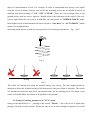
1
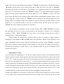
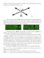
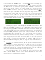
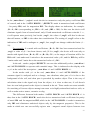
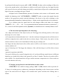
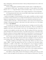
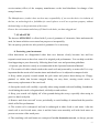
STINGER 2 User’s Operating Manual ______________________________________________________________________ Made in Bulgaria 1 In order to use the device for a maximum long time and without problems, as well as to be able to use all of its options, please read carefully the whole instruction manual and observe the directions in it. The standard set of STINGER 2 comprises: - searching frame 1x1m (or 1,20 x 1,20m.); - monitor unit with built in accumulators; - charger for 220 V; - charger for 12 V; - detailed instruction manual for operation. If any of these items are missing, immediately inf or m us, or our autorized dealer whe re you p urchased y our dete ctor. STINGER 2 has the following buttons for control: - Button „ON – OFF / CLEAR“ for switch on and switch off of the device and for automatic nullification to the soil conditions. - Buttons „SELECT“, „“ and ““ serve for work with the menu and the settings, choice of modes of discrimination and movement. - Button „STORE“ - serves for automatic setting of the device to earth conditions of a working terrain, and for memorization of definite objects or soil. - Button „MODE“ - used for switching between digital and graphic display of the indications for discrimination – ID1 and ID2 and switching between the Dynamic and the Static mode. - Button „VCO / DISCR“ - serves for switching between the mode of discrimination and the „VCO“ mode (multi – frequency sound) which also appears as common mode of searching for all metals. 1. Assembling of the device: Assembling the STINGER 2 is simple and you don’t need any special tools. When use the round coil 36cm. or 22x32cm.: The bearing rod is assembled by inserting of the lower part into the upper one. Choose the desired length of the whole construction and the fixing clamp is tightened between both parts of the bearing rod. The lower part of the bearing rod is put with the opening between the ears of the coil and the plastic bolt is tightened by choosing the 2 position of the coil to be parallel to the ground surface. Don't over-tighten the plastic bolt and nut to not damage the threading of the bolt! The coil cable is wind up tightly around the bearing rod and is switched to the terminal of the monitor unit. Upon switching of the cable of the coil to the monitor unit, tighten the well the metal nut of the coupling to the terminal of the box. Upon switching off, unscrew the nut completely and pull out the coupling without pulling or twisting the cable of the coil. This way, you will prevent the cable and the conductors in it from breakdown or short circuit. Finall y adj ust search coil angle to yo ur pref erence and yo u are read y. NOTE: Do not allow the cable to flop loosely over the search coil. Since the detector is sensitive enough to „see― the tiny wires in the cable, a floppy cable can cause false signals as the search coil senses the moving wires. The searching frame (coil) is approached to the surface of earth by paying attention to avoid presence of metals within its range. The cable is sub - connected to the de vice. Upon switching of the cable of the searching frame to the monitor unit, tighten the well the metal nut of the coupling to the terminal of the box. Upon switching off, unscrew the nut completely and pull out the coupling without pulling or twisting the cable of the coil. This way, you will prevent the cable and the conductors in it from breakdown or short circuit. When use the search frames 1x1m. or 2x2m.: The search frame should be held approximately 4 to 6 inch (10 to 15cm.) to ground surface while searching. Do not allow one end of the frame to be higher than the other. Make sure that no large metal objects are close to the search frame for initial adjustment. Also, check your shoes or boots since most of them contain metal parts and you would receive a signal response any time you step near to the coil. In order to avoid interference of the metal parts of the electronic unit, be sure to carry the STINGER 2 on the side of your body that is away from the search frame. The device is switched on through pressing of „ON – OFF / CLEAR“ and you see on the display: Start Detector, the serial number of the device and the software version. Starts balancing to the ground con ditions during whi ch ti me t he displ a y s hows "CLEAR " and yo u can hear a single sound. This lasts f or 3 – 4 sec., then it is f ollowed b y a dou ble short sound an d the de vice i s tur ned on i n ge ne ral mo de of "VCO" or last used mode . If you wish to w ork in a mo de of discri mi natio n 3 "DISCR ", yo u hav e to push the button " VCO / DISCR ", at which the device is switched in to discr imi nation mode an d the displa y sho w s " NORM AL DI S CR". 2. Working with the device in "VCO" mode In this mode the display shows "VCO". Constantly shown are the level of signal in digital or graphical appearance, the capacity of the accumulator, chosen power, the sensitivity, the level of co – working of the sound and the working mode, as follows: - 1st row to the left – the working mode – VCO, the chosen power P1 or P2 and the sensitivity of the device – S1, S2 or S3. - 2nd row to the left - capacity of the battery in percent: 0%-100% or time to work. - 3rd row to the left – the mode and the speed of searching – Dynamic or Static. The device can work in 8 modes of speed of searching – 4 static (for precise localization of an object) – „Static 1― - „Static 4―, and 4 dynamic (for searching while moving) - „Dynamic 1― - „Dynamic 4―. „Static“ are static modes of searching, i. e., the device constantly reacts to metal located within the range of the coil. They are suitable for localization of the precise position of an already located metal, and one can also work in those modes permanently. The fastest one is „Static 1“ mode, and the slowest one - „Static 4“. „Dynamic“ are dynamic modes of operation with different speed of searching. The difference in these modes is in the time for automatic nullification of appeared signals, i. e., the device is constantly additionally setting itself, but with various speed in various modes. The fastest one is the „Dynamic 1“ mode, and the slowest of all the dynamic modes is „Dynamic 4“. In these modes, the device reacts to metal objects within the range of the coil only upon movement of the coil above them. - 4th row to the right – „Level“ - the level of signal from the registered metal in figures – from 0 – 1000. If there is signal of metal within the range of the coil, disturbances or influence by soil, upon short pressing of "ON – OFF / CLEAR", this indication will become "0". After removal of the source of the signal from the coil range, indication will become of negative value. In order to be nullified, you have to push again "ON – OFF / CLEAR". During searching above ground surface, the indication for the level of signal hesitates (-1... 0... +1) or more, depending on the 4 degree of mineralization of soil. For example, in order to understand how strong is the signal from the soil on a definite location, one can lift the searching coil in the air and the device to be nullified with short pressing of "ON – OFF / CLEAR". Then, the coil is brought close to the ground surface and one can se opposite „Level“ what is the indication of the signal of the soil. Upon a signal from the soil of up to „Level: 20“ one can operate in "NORMAL DISCR" mode, but at higher levels of mineralization one has to switch to "auto discr" or "AUTO DISCR", which features are explained below. Searching metal objects is made by moving search coil toward ground surface – fig.1 , fig.2 Fig.1 Wrong Correct Fig.2 The search coil should not touch the ground during your sweep. The pole length should be adjusted to allow this without having to lift the detector with your elbow or shoulder. The search coil should rest about one inch above the ground while you are standing erect. The angle of the search coil should allow the bottom to be parallel to the ground. 2.1 Setting of working parameters in "VCO" mode setting of the threshold of co – working of the sound "Thresh" – this is the level of signal after passing of which a sound is heard. The device may be set at such strength of signal to react with 5 sound. This is done with change in the parameter "Thresh. For this purpose, through the buttons "◄ and ►" desired value can be selected from „0“ to „20“. The lower the value of „Thresh“, the greater the sensitivity of the device. For instance, if at a balanced device the constant signal from soil is "1" and we have chosen for "Thresh" a value of "1", then a sound signal is going to appear when the general signal becomes greater than "1". If for "Thresh" a value of "6" has been chosen, then the device is going to react with sound at a considerably stronger signal – value greater than "6". Greater values of "Thresh" can be selected if the general signal from the background of soil changes within wider limits, in order the device to be calm, aiming a sound signal not to be produced which is not due to detected metal, but the greater the value of „Thresh", the more sensitivity of the device decreases! At a presence of de-balance, one has to press shortly "ON – OFF / CLEAR", as at this, the searching coil has to be close to the ground, at the distance of search to be. Continuous pressing of "ON – OFF / CLEAR" for more than 4 sec will turn off the device, as this is accompanied by 3 short sound signals. Should within the range of the coil there falls an object, it produces a signal which is displayed on both indicators ID1 and ID2 and on the indication „Level“ of the intensity of the signal. Should this signal is louder than the threshold chosen of the sound „Thresh“, a sound is heard with a frequency which depends on the sound level. The greater the signal from an object, the louder the frequency of sound. This is a very convenient mode for precise localization of the location of an object. Pinpointing a Target A good method for pinpointing is "X-ing" the target with the search coil. Remember that the target's response sound is always greatest when the target is directly under the center of the search coil. To "X" a target, sweep the search coil over the target from side to side and then from front to back until you can identify the center of the X— the spot on the ground where the target response sound is the greatest. Pinpointing a target in Discriminate Mode is probably best done by "X-ing" as well. Remember that the detector will beep just as the target passes under the center of the search coil. Slowing the sweep speed down will help you pick out the center of the X, but remember that the search coil must always be moving slightly for target detection. Another easy method is to sweep the coil from side to side across the target in very short sweeps as you slowly move forward and backward across the target. Slow down the sweep rate and 6 shorten the sweeps until you just barely get a response at one spot. The target will be directly below the coil center at this response time – fig.3 fig.3 Upon short pressing of the „MODE“ button, the indications of the discrimination ID1 and ID2 turn on, as well as the intensity of the signal located, in digital or in graphic appearance. In graphic form the indicators may show positive or negative levels, respectively, increasing to the right or to the left from the dividing zero point of each of them. Continuous pressing of „MODE“ (for more than 3 sec.) switches between „Dynamic“ or „Static“ mode of searching, as this is also accompanied by sound signal. One has to also take into consideration that when using the fast modes 1 and 2, whether „Dynamic“ or „Static“, the consumption of the device is greater than in slow modes, i. e., in slow modes the device is more economic and can work longer with one charging of the accumulators. Fast modes of searching are suitable for searching in polluted sites and when using the smaller searching coils. It's preferred you to operate in modes 3 and 4, but if you wish to operate with the high speeds it is recommended that you decrease the power emitted to „P1“ and the sensitivity to be increased to „S3“. In this way, the consumption of the device will be decreased, without sensibly decreasing the depth of searching. By pressing of „SELECT“ you enter a menu where the following settings can be made: Coil – (1, 2, 3, 4) – choice of a program for searching coil. 4 different programs can be memorized for 4 different types of coils. Power – (1, 2) – choice of power of emission: 1 is decreased power, and 2 is normal Sens – (1, 2, 3) – choice of sensitivity of the device. Choice among 10bit, 11bit or 12bit АDC. 7 After each change of some of these 3 parameters, the device automatically restarts in order the respective settings to be loaded according to the selected values. „rejF“ (0 – 15) – through this parameter the device can be adjusted to decrease its sensibility to smaller objects without losing its sensitivity to bigger ones. This has its effect only in the mode with capital letters – AUTO DISCR. The greater the value of „rejF“ , the smaller the sensitivity to smaller objects. This function can be successfully used for elimination of the surface layer of soil, i. e., there to not be signals from smaller objects on surface, but to only react to deeper and bigger objects. dspB – (1,2,‖Clear cap?― ) : - “1” – capacity of the battery in percent: 0%-100% - “2” - working time. - “Clear cap?” – clear the capacity of the battery LCD – (0 – 7) – light of the display. 0 – turned off, and 1 – 7 – various brightness of light. If one accidentally pushes „SELECT“ and it is not necessary any changes to be made on the settings, the device can be turned again into operation position, through pushing and holding of „SELECT“ for 3 sec. 2.2. Setting of the operating parameters in „DISC“ mode „STINGER 2“ has 2 basic modes of discrimination - „NORMAL DISC“ and „AUTO DISC“, which are selected through pressing of button „VCO / DISCR“ as „AUTO DISCR“ has 8 sub – modes of operation. „AUTO DISCR“ has the following sub – modes - „auto discr“ and „AUTO DISCR“ as each of them has the function „accept / ACCEPT“ and „reject / REJECT“. Upon activated discrimination, beside the intensity of signal, upon location of metal, on 1st and 2nd row of the display to the right, both coefficients ID1 and ID2 are depicted, which, at registering of ferrous (magnetic) metal, have negative values, and at nonferrous (non – magnetic) metal – positive values. „ID1“ is a coefficient of purity of metal, and „ID2“ - coefficient of magnetism. Most often, upon localization of nonferrous metal ID1 and ID2 have great positive value, for example +13 and +9. Upon localization of magnetic (ferrous metal) – they have great negative value, for example -4 and -20. 8 Upon localization of foil, aluminium and unstained iron, ID1 and ID2 have their negative values, and both of them have great positive values express when the nonferrous metal is pure, without admixtures and alloys – gold, bronze, copper, silver. Upon localization of highly stained iron, ID2 has great negative value, for example -15 -20, and the indication of ID1 is around zero or +1, +2. They show that there is no sense this signal to be checked where it comes from. Foil, aluminium and aluminium alloys usually provoke signals around zero – for example „ID1 +2“ and „ID2 -5“. One has to also take into consideration that these indications can change through setting of „oID1“ and „oID2“ of the menu. ID1 and ID2 can have different values if within the range of the coil there is both nonferrous and ferrous metal or some alloy. The ID1 and ID2 coefficients appear only upon localization of metal, also in the „VCO“ mode, but in that case sound is multi – frequent one for more comfortable determination of the location of the object. Upon localization of an object, if the common signal becomes louder than „Level: 350“, the sound changes into a very low deep tone and on the first 2 rows to the right there appears the following: „discr overflow“. The digital indication continues to track the increase and if the level „Level: 1000“ of overflow is achieved, then the sound changes into a very high signal tone, and the display shows „OVERFLOW“ on the 4 th row of the display. In the modes of discrimination, „Thresh“ determines the minimum level of the signal after which there starts calculation of the coefficients „ID1“ and „ID2“. It cannot have values smaller than „5― in order to cooperate the sound signal of the discrimination at a comparatively low signal from the object. This is developed to avoid eventual error upon discrimination of very weak signals. In „NORMAL DISCR“ mode on the 2 nd row to the left of the display the balance indicator appears „|-|― for the background of the soil and shows whether the device is balanced at lack of signal. At a balanced device and lack of metal objects within the range of the coil, the indicator has to have 2 equal levels both from the left and the right side of 9 the symbol „_―. If there is a difference in both levels balance of the device should be performed through „POWER / CLEAR“. In the discrimination modes, with the pressing of „SELECT“, the following settings can be selected: „Low tone“ - (1, 2) – 1 is low tone turned off, and 2 is low tone turned on. „olD1“ - setting of the position of zero for the indication of ID1 – it can be moved to the left or to the right along the scale. I. e., if an object has an indication for ID1 – „+2“, if „olD1“ is decreased with 4 units, the indication for the same object will become „ -2“. In this way, some undesired alloys, stained iron items or caps and other objects of foil can be avoided and the device to register them with negative values , by preserving the positive indications for the „more ferrous― objects – coins, rings etc. „olD2“ - analogue to „olD1“, but for the indication of ID2. Discr (1, 2, 3, 4) – choice of a sub – mode of AUTO DISCR. / auto discr. rng1 (1, 2, 3) – choice of allowable range for the value of ID1 upon memorization of a definite object. rng2 (1 – 10) – choice of allowable range for the value of ID2 upon memorization of a definite object. The „AUTO DISCR“ mode is suitable when the background of the soil is negligibly small and doesn't change in considerable degree the signal received upon localization of a metal object. I. e., in it one can work on low mineralized or sandy soils. At a higher mineralization of soil, it gives a signal which can increase considerably, especially at approaching of the coil to cling to ground surface. Highly mineralized soils, especially when containing a considerable amount of moisture, additionally increase the common signal and it can have great values. If in such type of soil there is nonferrous metal, it will change the common signal to more positive values, but to overcome the background of the soil, the signal to the object will have to be considerably stronger, i. e., the sensitivity because of the background will decrease. For such cases suitable are the „auto discr“ / “AUTO DISCR“ modes. The next mode of discrimination is „auto discr“ / “AUTO DISCR“ with a sub – mode „accept / ACCEPT“. In this sub – mode the device will not produce any sound signal until it memorizes a definite nonferrous metal, and the indication on the 3 rd row to the right of the display is: “accept... or ACCEPT...“. The memorization of a definite metal 10 is done as follows: the „STORE“ button is pressed and held and to the searching coil a definite type of nonferrous metal is approached, the indicators for the type of metal „ID1“ and „ID2“ show the type of metal and against „accept / ACCEPT“ a definite figure is depicted (as per the type of metal) - for example „accept: +12“. Then user can release button „STORE“ and will hear double beep! In this case the device will react only to metals with own signal „+11, +12 or +13“, if for the parameter „rng1“ a value of „1“ has been chosen. If the value of „rng1“ increases to „3“, the device will react with a sound and at signals of „+9― to „+15“, i. e., the range increases with 3 more units under the memorized value and 3 units over it. The device will not have sound indication of any signals smaller than „+9― and greater than „+15“. The difference in the sub – modes “accept“ and „ACCEPT“ corresponding to „auto discr“ and “AUTO DISCR“ expresses in that at „auto discr“ the device memorizes only the coefficient for purity ID1 of metal and the display shows for example: “accept: +12“. At an “AUTO DISCR“ mode the device memorizes both coefficients – for purity ID1 and for magnetism ID2. An indication appears on the display, for example: „A: +12, +10“ (corresponding to „ID1 = +12― and „ID2 = +10“). In this case the device will produce a sound from located metal only if both memorized coefficients coincide. I. e., it will work in a more precise way, but beside „rng1“, the value of „rng2“ will also be the one that will matter, as ID2 is also taken into consideration. The setting of „rng2“ refers to the indication of ID2 and is analogue to „rng1“, but „rng2“ can change within the limits (1 – 10). For example: if a metal with coefficients „A: +12, +10“ has been memorized and for „rng1“ a value of „1“ has been chosen, and „3“ for „rng2“, the device will react only to metals with signals from „A: +11, +7― to „A: +13, +13“, or the ranges of location will be for ID1 with 1 unit under and 1 unit above the memorized value „+12“, and for ID2 they will be 3 units under and 3 units above the memorized value of „+10“. Upon following pressing of „VCO / DISCR“ the device is switched into „auto discr“ / “AUTO DISCR“ with sub – modes „reject / REJECT“, at which definite undesired objects can be memorized and eliminated. 11 In the „auto discr“ / „reject“ mode the device memorizes only the purity coefficient ID1 of a metal, and in the “AUTO DISCR“ / „REJECT“ mode it memorizes both coefficients – for purity ID1, and for magnetism ID2. The display shows an indication, for example: „R: -9, -28“ (corresponding to „ID1 = -9“, and „ID2 = -28“). In this case the device will eliminate signals from a located metal, only if both memorized coefficients coincide. I. e., ti will operate more precisely, but beside „rng1“, the value of „rng2“ will also be the one that will matter, as ID2 is also taken into consideration. The setting of „rng2“ refers to the indication of ID2 and is analogue to „rng1“, but „rng2“ can change within the limits (1 – 10). For example: if a metal with coefficients „R: -9, -28“ has been memorized and for „rng1“ a value of „1“ has been chosen, and „3“ for „rng2“, the device will react only to metals with signals from „R: -8, -25― to „R: -10, -31“, or the ranges of location will be for ID1 with 1 unit under and 1 unit above the memorized value „-9“, and for ID2 they will be 3 units under and 3 units above the memorized value of „-28“. In the sub – modes „reject / REJECT“ one can also additionally select „auto discr“ and “AUTO DISCR“ to operate with extended range. This is indicated on the display with a „+“ at the end of the inscription - „auto discr +“ and “AUTO DISCR +“. In the modes with „+“ at the end, „auto discr +“ and “AUTO DISCR +“ the common signal is analyzed and at a change, one calculates what part of it is d ue to the background of the soil, and what part is provoked by another object. That is the way of calculation what is the signal only from the object, it is close to that one, if soil doesn't have its own background or the object is situated in the air. These modes are most suitable for searching of ferrous objects among iron waste or in highly mineralized and ore soils, as well as under active stones, ceramics or slag. The difference between both modes: “AUTO DISCR“ and “AUTO DISCR +“ is that, that in the “AUTO DISCR“ mode the device memorizes both coefficients for purity of metal ID1 and for magnetism ID2, while in the “AUTO DISCR +“ mode it memorizes only ID2 and eliminates undesired objects only by the magnetic properties. This is the mode in which one can successfully register non – magnetic metal objects between iron 12 items or under active stones and highly mineralized soils. In this case, if, for example, an object (stone, ceramics or some iron) has been memorized, with own signal of „-28“, the device will not react to any signals smaller than „-28“, and each signal greater than „-28“ will be registered with sound, as the objects „with more positive signal― (from „-27― to „0“) will be signalized with a low tone, and all positive ones – with high tone. If from the menu for „Low tone“ a value of „1“ has been selected, for the negative signals there will not be low tone and the device will react with high tone only for the positive signals, i. e., for the nonferrous metals. Analogue is the operation of the device also when working in an „auto discr +“ mode – all metals with a signal more positive than the memorized one will be signalized, and all having values lower than the memorized, will be eliminated. The difference between the„auto discr +“ and “AUTO DISCR +“ modes is that at a selected mode with capital letters the device operates more effectively for bigger objects and can successfully memorize and eliminate undesired bigger objects or more active soils (in „REJECT“ mode). When operating in „auto discr +“ / „reject“ mode, the device can successfully memorize and eliminate undesired smaller objects – for example wire and small nails, and to effectively search for coins, rings or other small objects, but in this mode very big objects or very high mineralization of soil can provoke undesired misleading signal. In such cases it is recommended the device to operate in „AUTO DISCR +“ mode. The modes with „+“ can be selected by pressing the button „SELECT“ until the „discr“ parameter appears, and one has to choose either „discr 3“ for „auto discr +― or „discr 4“„AUTO DISCR +“. Switching between the modes with „+“ and without „+“ can be done also during work with pressing and holding of the buttonh „VCO / DISCR“ for more than 3 sec., but this can be done only in the sub – modes „reject / REJECT“. 3. Balancing to the background of the soil in the discrimination modes. Usually, „light― weak mineralized soils have their own signal of up to „ Level: 15 – 20“. On them, one can work in a "NORMAL DISCR" mode, and the only balancing which can 13 be performed in this mode is to press „ON – OFF / CLEAR“ for short, as the searching coil has to be close to the ground surface, at the distance at which one will search. In this way, the signal from the soil is perceived as zero and each change provoked by a metal object will provoke a sound signal with high or low tone, according to the type of metal. At higher levels of mineralization, presence of moisture, active stones or old ceramics, most suitable for balancing is the "AUTO DISCR + / REJECT" mode, as most often signals from the surface of the ground are positive and the balancing of the device to the soils is analogue to the memorization and elimination of undesired objects – in that case the signal from the soil is undesired. If at a definite point, the signal from the soils changes within wide limits, for example: "REJECT: „-20― / „-40― / „-60― , it is recommended that the minimum deviation is memorized - „20―, or one to work in the dynamic modes „Dynamic“, in which the device constantly balances itself. 4. The detection depth depends on the following: -size, shape and location of the object in the soil. The bigger the reflecting surface of the object the deeper it is to be found; -soil composition and mineralization level – the drier and more homogeneous the soil the easier it will be to adapt the device and for the device to detect deeper. Under stones, dry sand or in clay utensil, metals are easier to be found than in freshly dug out or damp soil. -the longer the object has been in the soil the easier it will be to be found as a result of the good contact with the soil. -type of detecting coil. The bigger the diameter of the coill the deeper it will be able to detect metals. -operator's experience and skills. You can do field tests by yourself using the device if you bury different metal objects in different depth but you should leave them in the ground for at least 3 months. Thus the test results will be more reliable. You should mind the soil type and the moisture composition in it. Best results are received when the soil is dry. 5.Charging storage batteries and indications for their status. ―STINGER 2‖ has a built-in storage package 14,4V / 2,2Ah, which is able to provide 1015 hours of working process without any interruption depending on the chosen power and the type of the used search coil. Bigger coils consume more power and thus the working time is shorter. 14 The accumulators' status is shown on the first row on the right as per cents of the capacity (0%-100%). When the capacity decreases below 0% it will show ―Low bat‖ and if fully charged batteries or if using external supplying block with higher voltage it will show ―+++‖. The charging is automatic and begins when the device is SWITCHED OFF and you plug the charger into the charging jack of the back panel of the device. The jack cage is ―-‖ and the middle terminal is ―+‖. During charging on the display you will see transitory and maximum voltage of storage batteries, their temperature, as well as the charged so far capacity and on the lower row of the display ―Charging‖. The charging continues till the moment when the batteries reach their maximum capacity which also reflects in increase in the temperature. When reaching their full capacity and increase in the temperature up to 40ºC the charging stops and down on the display you will see ―FULL‖. At the same time the device will start to make short sound signals. Charging depending on the level of discharge of the batteries. It’s not necessary to keep eyes on charge device, because it is supplied with automatic turn off and batteries couldn’t be damaged no matter how long they will stay in the charge device. When they are ready pull the device out of the electric net and take the jack out of the ―CHARGE‖ NOTE: Don’t unplug the c harger i f charge pr ocess i s n ot fini shed. Always charge device's storage batteries ONLY with the paired chargers to it. Thus you will prevent damages or confusion between “+” and “-” because the use of other chargers or adaptors may lead to irretrievable damages in the batteries! 6. Possible problems during exploitation of “STINGER 2”: 6.1.When switching it on you can not hear a sound, there is no information on the display, no indication that the device is switched on. It might indicate for: - storage batteries are dead (usually after a long period of time). Charge the batteries with the charger. If the problem is not solved contact the service-station (office) of the company manufacturer or the local distributor. - the accumulator block consists of 13 elements 1,2V/2700mAh connected in series. If just one of 15 them is damaged the connection between them is destroyed and practically the device will be left without power supply. 6.2. The working depth is significantly shallower than the normal. It might indicate for: - storage batteries could be dead – pay attention to the shown % for the capacity of the storage batteries. If it is ―---‖ charge the batteries with the automatic charger. If you can not solve the problem contact the service-station (office) of the company manufacturer or the local distributor. 6.3. During detection the device does not work stable, makes strange sounds which are not due to a metal detection. It might indicate for: - irregular electromagnetic external interruptions. False signal or instability can often be caused by situations outside of the detector. For example electrical interference from power lines or other high power transmitting devices. Often these devices can be identified, sometimes they can not. - problems with the aerial cable – disconnected conductor, a shot circuit or bad connection in the coupling. If disconnected conductor or shot circuit in the cable on the lower row of the display you will see ―COIL ERROR‖. It is possible after continuance work and many times of switching on and off the cable's coupling to the jack box the contact between them to be destroyed. There are 4 terminals with sightholes in the jack of the back panel of the device. Put something sharp like a knife or a screwdriver in the sightholes and make them wider. Thus the coupling will fit better into the jack which will improve the contact between them. It is possible in the presence of some kind of dirty like dust or moisture to clean the terminals with cotton-wool and alcohol. If you can not solve the problem contact the service-station (office) of the company manufacturer or the local distributor. 6.4. The device works only with headset and when working with amplifier you can not hear a sound. Usually that happens when the headset jack is damaged. In that case contact the service-station (office) of the company manufacturer or the local distributor to change the jack. 6.5. When switching on the charger to charge the storage batteries you will see on the display ―FULL‖. Usually that happens when the device was kept in the cold and the battery temperature is around or below 0ºC. If the microprocessor can not define the batteries temperature you can not strat the charging and on the display you will see ―FULL‖. Leave the device in a warm premise and wait till the temperature of the batteries increases up to 5- 6ºC. If you can not solve the problem contact the service-station (office) of the company manufacturer or the local distributor and do not charge with any other devices or ordinary adaptors. 6.6. Batteries charge quickly and after that during the working process they go dead quickly. Usually that happens when the batteries are really old and need replacement. Contact the 16 service-station (office) of the company manufacturer or the local distributor for change of the storage batteries. The Manufacturer (trader) does not bear any responsibility if you use the device in violation of the law, on archeological or forbidden for search places as well as on private property without the knowledge or the permission of the owner. Protect the environment and always fill back in the holes you have dugged out! 7. GUARANTEE The detector STINGER 2 is offered with 2 years of guarantee of electronics, labor and materials used, for harms which are not caused on purpose or irresponsibly. We can upkeep your device after period of guarantee if it is necessary. 8. Protecting your investment Often detectorists are disappointed when their new detector slowly becomes less and less responsive and seems to have lost some of its original peak performance. You can help avoid this from happening to your detector by following these basic care and protection guidelines: Operate your detector exactly as recommended in this Operator Instruction Manual. The search coil cable is hard-wired to the search coil and protected by a strain relief. It is very important that the strain relief remains intact and should never be adjusted or tampered with. Keep cables properly wound around the pole stems and protect them during use. Floppy, pinched, or cables that become snagged during use may short, causing erratic noises or unnecessary replacement of the search coil. Sweep the search coil carefully, especially when using around rocks and building foundations. Avoid hitting the search coil against hard, solid objects and surfaces. Keep your search coil slightly off of the ground during the sweep, especially when using in gravel or hard, rocky dirt. Remove and clean out scuff covers periodically to avoid buildup of mineralized dirt particles which will affect performance. The search coil is waterproof and can be submerged in either fresh or salt water. After the search coil is used in salt water, rinse it and the lower stem assembly well with fresh water to prevent corrosion of the metal parts. The searching coils and frames are waterproof but the electronics are not, so always prevent 17 any moisture or water from entering the control housing and never allow the cable connector to become submerged in water. If working in or near water, or if there is a possibility of rain, use a protective weather resistant pouch or plastic bag to cover the control housing. Make sure it can "breathe" in order to ensure against condensation buildup inside. After each use, clean the detector with a soft cloth to remove dust, moisture, or other contaminants. When transporting the detector in a car during hot weather, store it on the floor of the passenger compartment if possible. Using a carry bag gives additional protection. In any case, never allow the detector to roll around unprotected in the trunk or back of a pickup truck. Protect your detector from dust, moisture, and extreme temperatures during storage. Treat your detector as you would any sensitive electronic instrument. Though ruggedly constructed and designed to withstand the demands of normal treasure hunting, proper care is essential. www.mikronbg.com 18