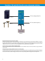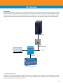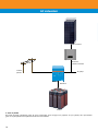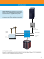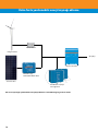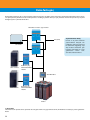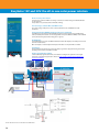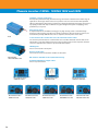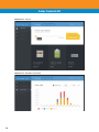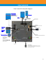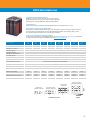
1
Enerji, her zaman, her yerde ŞEBEKEDEN BAĞIMSIZ YEDEKLEME VE ADA SİSTEMLERİ 2 INDEX Giriş6 Uygulama örnekleri 7 Fener 8 Hospital 10 Kullanıma hazır şebeke ünitesi 12 DC sistemleri 14 AC sistemleri 17 Daha fazla yenilenebilir enerji kaynağı ekleme 20 Aksesuarlar21 Daha fazla güç 22 Teknİk bİlgİler 25 Victron Energy hakkinda 80 Wood shack with solar cell roof, Germany/Hollandse Hoogte 3 EasySolar 12V and 24V: the all-in-one solar power solution AC out, always active (3) Solar in AC out, active on grid (1) AC in Battery EasySolar: The all-in-one solar power solution EasySolar takes power solutions one stage further; by combining an Ultra-fast BlueSolar charge controller (MPPT), an inverter/ charger and AC distribution all in one enclosure. With an extensive reduction in wiring, EasySolar provides ease of use combined with a maximum return on investment. When using the 24V model, it is possible to use up to 1400 Watt of solar power and with 1600VA continuous inverter power, even peaks of 3000 Watt can be handled without any problems. The solar charge controller: BlueSolar MPPT 100/50 Up to three strings of PV panels can be connected with three sets of MC4 (PV-ST01) PV connectors. Efficient energy distribution is guaranteed. Inverter/charger providing 1600 VA continuous inverter power The MPPT charge controller and the inverter/charger share the DC battery cables so no additional wiring is needed. The batteries can be charged with solar power (BlueSolar MPPT) and/or with AC power (inverter/charger) from the utility grid or a genset. Consumers are always assured of energy, even when the sun isn’t providing sufficient energy for electrical appliances. 4 EasySolar 12V and 24V: the all-in-one solar power solution VE.Direct MPPT 100|50 5 Giriş Şebekeden bağımsız İşlevsel bir elektrik şebekesinin varlığı her zaman göründüğü kadar bariz değildir. Güvenilmez bir şebekenin nedeni genellikle yetersiz bir altyapıdır. Hiç şebeke yoksa işler daha da zorlaşır. Ancak yine de güvenilir bir elektrik kaynağına ihtiyaç duyulur. Bu noktada tek cevap yerel ve doğru bir şekilde çalışan bir sistemdir. Victron Energy size bu cevabı sunuyor.Özgürlük ve bağımsızlığın modern tercümesini size sunmaktan gurur duyuyoruz. Enerji, Her Zaman, Her Yerde Hibrit sistemler Kullanılabilir tek enerji kaynağı güneşse, çözüm basit. Enerji talebinizi karşılamak için bir güneş sistemi tercih edeceksiniz.Eğer daha fazla kaynak kullanılabiliyorsa, bunlar da güneş sisteminizi destekleyebilir. Güneş enerji talebinizi tamamenkarşılayamadığı için bir güneş sistemi genellikle bir jeneratörle veya bir rüzgar jeneratörüyle desteklenir. Bu enerji kaynakları güneş açığının karşılanmasını sağ 6 Uygulama örnekleri Fener Hospital Kullanıma hazır şebeke ünitesi 7 Fener Saldanha, Güney Afrika’da şebekeye bağlı olmayan fener Güney Afrika sahillerinde şebekeye bağlı olmayan birkaç fener, eskiden 12kW’lık üç adet eski jeneratörle çalıştırılıyordu. Eski jeneratörler, jeneratör gücüne temiz ve sessiz birer alternatif olan yeni Solar sistemiyle değiştirildi. Üretilen enerji, fenerlerdeki telsiz iletişimi, ışıklar ve yakındaki gemilerin radar sinyallerini algılamak için özel radar ekipmanı gibi tüm yüklere elektrik vermek için kullanılıyor. Yeni Solar sistemi aşağıdakilerden oluşuyor: • 2 adet paralel 48/3000/35 MultiPlus • 1500Ah C10 OPzS 2V’luk aküler • 16 adet 230 Wp Solar Panel • BlueSolar Şarj Kontrol Birimi MPPT 150/70 • Yedek olarak 10kW’lık jeneratör • Ana akü şarj ünitesini ve jeneratör aküsünü izlemek için Hassas Akü Ekranı BMV-602S. BMV-602S, akü şarj ünitesinin şarj durumuna göre jeneratörü otomatik olarak başlatır ve durdurur. • Uzaktan İzleme için I/O Extender (Uzatıcısı) ve ayrıca Uzaktan Jeneratör başlatma işlevi olan bir Victron Global Remote. 8 Fener BlueSolar 150/70 Mppt Blue Solar MPPT 150/70 2 2x xMultiPlus Multiplus VGR-2 VGR-2 victron global remote P O W E R B L U E victron energy I/O Extender I/O Extender AC distribution B L U E P O W E R victron energy MK2.2a BMV-602 battery monitor SETUP + - SELECT Battery monitor Battery monitor Jeneratör Generator OpzS OpzS OpzS OpzS OpzS OpzS Akü Paketi Battery pack Fenerdeki kurulumun sistem şeması. 9 Hospital Cap-Hatian, Haiti’de yardım derneği tarafından işletilen hastane Haiti’deki yıkıcı depremin ardından, halk hala evlerini yeniden inşa etmeye ve toparlanmaya çalışıyor. Cap-Haitian, Haiti’deki yardım derneği tarafından işletilen hastanede, tüm hastaneye güç sağlamak için kapsamlı bir hibrit güç sistemi kuruldu. Sistemin kalbinde paralel olarak bağlanmış beş adet Victron 24/5000/120 Quattro’s var. Sadece yüz amper kapasitesinde küçük bir şebeke bağlantısı mevcut. Gerekli gücün daha yüksek olduğu durumlarda, Quattro’s şebekeye akülerden gelen enerjiyi sağlayacaktır. Bu invertörlerin çıkışını şebekeyle senkronize eden PowerAssist adında benzersiz bir Victron özelliğidir. Şebekeye etkin bir şekilde güç ekler. Yük azaldığında, akü şarj ünitesini yeniden şarj etmek için yedek güç kullanılır. Çok küçük olmanın yanı sıra, şebeke bağlantısı aynı zamanda güvenilmezdir. Bir şebeke gücü kaybı durumunda, Quattro’s görünmez bir şekilde güç talebini sağlar, böylelikle Hastane güvenilebilir bir güç kaynağına dayanabilir. Ayrıca güç kesintisi yeterince hızlı bir şekilde giderilmediği durumda 40kVA’lık jeneratörü otomatik olarak başlatır. Hastanenin altı binasının tamamı toplamda 8 adet 180W solar panelle tamamen kaplanmıştır. Bu paneller yüklere güç veren şebeke invertörleri vasıtasıyla Quattro’nun çıkışlarına bağlıdır. Tüm aşırı güç aküleri şarj etmek için kullanılır. 10 Hospital Günes Panelleri BlueSolar Şebeke invertörü 5 x Quattro 5kVA 1’DE AC Şebeke 2’DE AC Jeneratör Aküler Haiti’deki tesisata genel şematik bakış 11 Kullanıma hazır şebeke ünitesi İngiltere: ‘Kullanıma hazır şebeke’ ünitesi dış mekan etkinlikleri için enerji sağıyor. Dış mekan etkinlikleri, genellikle, kullanılan ekipman için yüksek miktarlarda enerji gereksinimini beraberinde getirir. Bir dış mekan etkinliğinde ana şebekeye erişim yoksa, elektrik ihtiyacının karşılanabilmesi için uygulanan başlıca yollardan biri jeneratör kullanmaktır. Ancak, jeneratörler gürültü çıkarırlar ve ciddi anlamda hava kirliliğine neden olurlar. İngiltere’den bir firma bu soruna doğal ve yeşil bir çözüm getiriyor: ‘Kullanıma hazır şebeke’ ünitesi. Kullanıma hazır şebeke Kullanıma hazır şebeke ünitesi, enerji üretimi için temiz ve sessiz bir alternatiftir. Lityum-iyon pillerde depoladığı enerjiyi kullanırken, yenilenebilir enerji (güneş ve rüzgar) kaynaklarından da yararlanarak boşalan pillerini doldurabilir. Kullanıma hazır şebeke ünitesinin iki versiyonu bulunmaktadır: biri, entegre jeneratörlü ve yakıt tanklı ünite, diğer ise, ‘mini’ olan jeneratörsüz ünite. Her ikisi de güneş panelli olarak temin edilebilir. Victron Energy ekipmanları Kullanıma hazır şebeke ünitesi tamamen Victron Energy ile donatılmıştır: 24V 180Ah Lityum-iyon piller, tek fazlı veya trifaze kullanılabilen 2 veya 3 Quattro 48V 8kVA ünitesi, Lynx kutuları ve Victron Energy'nin sunduğu diğer ürünler. 12 Kullanıma hazır şebeke ünitesi Multi 5 1 20 AC distribution Lynx Power In Lynx ION IN Lynx Shunt ION Shunt Lynx Distributor Distributer VE.CAN LITHIUM BATTERY 24V / 180Ah BMS CAN-BUS Ion Control MG LITHIUM BATTERY 24V / 180Ah MG Lithium battery set ‘Kullanıma hazır şebeke’ ünitesinin şematik görünümü. 13 DC sistemleri DC Sistemleri DC sistemlerinde, güneş enerjisi regüle edilmiş DCa dönüştürülür. Sonuç olarak, regüle edilmiţ DC pillere ve tüketicilere sađlanir. Bir invertör DC sistemine bađli AC tüketicilerine güç sađlar.s DC sistemlerinin aksine, güneţ enerjisi AC sistemlerinde dođrudan ACa dönüţtürülür. DC Çikiţi BlueSolar şarj kontrolörü MPPT 70/15 Solar Paneller Aküler 1. DC tüketicileri Bir güneţ paneli pratikte tüketicilere dođrudan güç sađlar. Panel ile güç tüketicisi arasindaki tek madde ţarj kontrol birimidir. Bu Blue Solar Şarj Kontrol Birimi tüketiciler ve aküler için voltajlari kontrol eder. DC tüketicileri dođrudan akülere bađlidir. 14 DC sistemleri AC ÇIKIŞI BlueSolar şarj kontrolörü MPPT 70/15 Phoenix invertör Solar Paneller 12,8V Lithium-ion piller 2. AC tüketicileri Bu AC tüketicilerine yönelik 230 Volt çıkışa sahip bir DC sistemidir. Yukarıdaki örnekte, AC çıkışı sağlamak için bir Victron Phoenix invertör eklenir. AC ÇIKIŞI Jeneratör MultiPlus Solar Paneller BlueSolar şarj kontrolörü MPPT 150/70 Aküler 3. Yeterli güneş mevcut değil – hibrit güç Güneş yeterli enerji sağlamıyorsa, sisteme bir jeneratör eklenir. Bu durumda, bir invertör yerine bir Multiplus invertör/şarj cihazı kullanılır. Jeneratör doğrudan MultiPlus’a bağlıdır. MultiPlus solar güç kullanımını en üst seviyeye çıkarıp uzun bir akü ömrü sağlarken, otomatik olarak jeneratörün çalışmasını ve durmasını düzenler. 15 DC sistemleri PowerAssist – şebeke veya jeneratör gücünün kapasitesini yükseltir Bu benzersiz Victron özelliği MultiPlus’ın şebeke veya jeneratör gücü kapasitesine ilave yapmayı sağlar. Pik gücün genellikle sadece sınırlı bir süre için gerektiği durumlarda, MultiPlus yetersiz kıyı veya jeneratör gücünün derhal aküden alınan güçle telafi edilmesini sağlar. Yük azaldığında, akü şarj ünitesini yeniden şarj etmek için yedek güç kullanılır. Dolayısıyla, maksimum pik yükte bir jeneratörü boyunlandırmak gerekmez. Bunun yerine en etkin boyutta jeneratörü kullanın. Not: Bu özellik hem MultiPlus’ta hem de Quattro’da mevcuttur. Quattro 1’DE AC Şebeke ANA AC ÇIKIŞI YARDIMCI AC ÇIKIŞI 2’de AC Jeneratör Solar Paneller BlueSolar şarj kontrolörü MPPT 150/70 24V Lithium-ion piller 4. Yedek sistem Solar enerji bir şebeke bağlantısıyla da kombine edilebilir. Ancak yetersiz bir solar kaynakla birlikte güç kesintileri yaşayan bir şebeke bir jeneratör desteğine ihtiyaç duyar. Bir MultiPlus yerine size hem şebekeye hem de jeneratöre bağlamak için tümleşik bir aktarma anahtarına sahip bir MultiPlus olan Quattro’yu öneririz. Bu şebeke ile jeneratör arasındaki anahtarlama işlemini tamamen otomatik hale getirir. 16 AC sistemleri AC Sistemleri Genellikle AC tüketicilerine güç sağlayan daha büyük solar sistemler için, solar gücü derhal AC’ye dönüştürmek daha verimlidir. Bu nedenle bunlara “AC sistemleri” denir. AC sistemleri DC sistemlerine kıyasla daha yüksek bir enerji verimliliğine sahiptir. BlueSolar Şebeke İnvertörü solar enerjiyi doğrudan AC’ye dönüştürür. Bu invertör bir MultiPlus veya Quattro tarafından sağlanan bir “şebekeye” ihtiyaç duyar. AC tüketicileri tarafından kullanılmayan solar güç fazlası aküleri şarj etmek için kullanılır. Solar Paneller BlueSolar Şebeke invertörü AC ÇIKIŞI Jeneratör MultiPlus 24V Lithium-ion piller 1. Jeneratörlü ada sistemi Enerji solar paneller tarafından toplanır toplanmaz, Blue Solar Şebeke İnvertörü tarafından AC’ye dönüştürülür. Jeneratör alternatif akımını doğrudan MultiPlus invertör/şarj cihazına sağlar. MultiPlus solar güç kullanımını en üst seviyeye çıkarırken jeneratörü otomatik olarak çalıştırıp durduracaktır. 17 AC sistemleri Solar Paneller BlueSolar Şebeke invertörü 1’DE AC Şebeke AC ÇIKIŞI MultiPlus Aküler 2. Solar ve şebeke Bu yedek sistemde, şebekeden gelen AC solar panellerden gelen enerjiye ilave yapabilir. Ve aynı şekilde, solar panellerden gelen enerji oluşabilecek tüm şebeke kesintilerini telafi edebilir. 18 AC sistemleri MultiPlus’a karşı Quattro MultiPlus ve Quattro ürünleri hem AC hem de DC sistemlerinde önemli bir rol oynar. Her ikisi de bir kutu içerisinde güçlü akü şarj cihazları ve invertörleridir. Mevcut AC kaynaklarının miktarı Quattor ile Multi arasında seçim yaparken belirleyici faktördür. Asıl fark akıllı kurallara bağlı olarak bir Quattro’nun iki AC kaynağı ve bunların arasında bir anahtar alabilmesidir. Tümleşik bir aktar ma anahtarına sahiptir. MultiPlus yalnızca bir AC kaynağı alabilir. Solar Paneller BlueSolar Şebeke invertörü 1’DE AC Şebeke ANA AC ÇIKIŞI YARDIMCI AC ÇIKIŞI 2’DE AC Jeneratör Quattro Aküler 3. Solar, jeneratör ve şebeke Burada gösterilen gibi kapsamlı bir yedek sistem kesintisiz bir enerji tedariki sağlar. Örneğin, bir şebeke kesintisi gerçekleşir, aküler boşalır ve aynı zamanda mevcut olarak kısıtlı miktarda solar enerji olursa, Quattro invertör/şarj cihazı jeneratörü çalıştırır. Jeneratöre artık ihtiyaç duyulmadığında, otomatik olarak durdurur. 19 Daha fazla yenilenebilir enerji kaynağı ekleme WIND CONVERTER Kontrol Birimi Rüzgar Türbini AC ÇIKIŞI Phoenix invertör BlueSolar şarj kontrolörü MPPT 70/15 Solar Paneller 2 x Lithium 12,8V pil Seri bağlamalı DC vasıtasıyla diğer yenilenebilir enerji kaynaklarının nasıl ekleneceğini gösteren örnek 20 Aksesuarlar Solar sistemlerimiz çeşitli bileşenlerden oluşur. Bunlardan bazıları solar sistemler için özel olarak tasarlanır. Diğer Victron bileşenlerimiz geniş bir takım uygulamalar için kullanılabilir. Bu bileşenler hakkındaki teknik özellikleri ve diğer detaylı bilgileri ’de “Teknik Bilgiler” bölümünde bulabilirsiniz. Akü Monitörü Victron Akü Monitörünün temel görevleri şarj ve deşarj akımlarının ölçülmesi,ayrıca şarj durumunu ve akünün kalan süresini hesaplamaktır. Belli limitler aşıldığında bir alarm gönderilir (örneğin aşırı deşarj). Akü monitörünün Victron Global Remote ile veri alışverişi yapması da mümkündür. Bu alarmların gönderilmesini de kapsar. Color Control GX The Color Control GX provides intuitive control and monitoring for all products connected to it. The list of Victron products that can be connected is endless: Inverters, Multi’s, Quattro’s, MPPT 150/70, BMV-600 series, BMV700 series, Skylla-i, Lynx Ion and even more. VRM Online Portal Besides monitoring and controlling products on the Color Control GX, the information is also forwarded to our free remote monitoring website: the VRM Online Portal. To get an impression of the VRM Online Portal, visit https://vrm.victronenergy.com, and use the ‘Take a look inside’ button. The portal is free of charge. Dijital Çoklu Kontrol Paneli Bu panel ile, Multiplus ve Quattro sistemlerini uzaktan izleyebilir ve kontrol edebilirsiniz. Düğmenin basit bir hareketle döndürülmesi örneğin bir jeneratörün ve/veya kıyı tarafı akımının güç kaynağını sınırlayabilir. Ayar aralığı en fazla 200A’dır. 21 Daha fazla güç Bu broşürde gösterilen AC ve DC sistemleri Victron Energy’nin sunduğu çeşitli imkanların örnekleridir. Gösterildiği üzere, basitten çok kapsamlı çözümlere kadar farklılaşabilirler. Gerekli güç tek bir ünite için çok yüksekse ürünlerimiz paralel veya üç-fazlı konfigürasyonlar şeklinde konulabilir. MultiPlus invertör / ţarj cihazlari AC ÇIKIŢI Jeneratör Solar Paneller Yapılandırılması kolay Paralel ve üç fazlı sistemleri yapılandırmak kolaydır. VEConfigure yazılım aracımız hiç bir donanım değişikliği veya dip anahtarı olmaksızın yükleyicinin bileşenleri bir araya getirmesine imkan tanır. Standart ürünleri kullanır. BlueSolar şarj kontrolörü MPPT 150/70 Akü Monitörü Solar Paneller BlueSolar şarj kontrolörü MPPT 150/70 Aküler 1. DC sistemi Yukarıdaki resim paralel tek bir jeneratör olarak yapılandırılan üç şarj kontrol birimi, iki MultiPlus invertör/şarj aletini göstermektedir. 22 Daha fazla güç Solar Paneller 3 BlueSolar Grid invertör 2 Paralel Quattro’s 1’DE AC Şebeke ANA AC ÇIKIŞI 2’DE AC Jeneratör YARDIMCI AC ÇIKIŞI Akü monitörü Aküler 2. AC sistemi Yukarıdaki resim paralel olarak üç şebeke invertörüne ve iki Quattro’ya sahip bir AC sistemini göstermektedir. 23 Not: En yeni veri sayfalarımız için lütfen websitemize bakınız: www.victronenergy.com 24 TEKNİK BİLGİLER Phoenix inverters 180VA - 1200VA 120V and 230V Phoenix inverters 1200VA - 5000VA 230V Multiplus inverter/charger 800VA- 5kVA 230V Quattro inverter/charger 3kVA - 10kVA 230V MultiPlus inverter/charger 2kVA and 3kVA 120V Quattro inverter/charger 3kVA - 5kVA 120V Skylla-i battery charger 24V Skylla charger 24/48V Skylla TG charger 24V 90-265V GL approved Victron Global Remote 2 and Victron Ethernet Remote Victron Global Remote 2 and Victron Ethernet Remote BMV-700 series: Precision battery monitoring BlueSolar monocrystalline panels BlueSolar polycristalline panels BlueSolar charge controllers MPPT 70/15 BlueSolar charge controllers MPPT 75/50 BlueSolar PWM charge controllers Telecom batteries OPzS Solar batteries 12,8 Volt Lithium iron phosphate batteries BMS 12/200 for 12,8 Volt lithium iron phosphate batteries 24V 180Ah Lithium-ion battery and Lynx-ion Gel and AGM batteries Phillippines/Hollandse Hoogte 28 30 32 34 36 38 40 42 44 46 47 54 58 59 62 63 66 68 69 70 72 74 76 25 25 EasySolar 12V and 24V: the all-in-one solar power solution www.victronenergy.com EasySolar 12V and 24V: the all-in-one solar power solution z All-in-one solar power solution The EasySolar combines a MPPT solar charge controller, an inverter/charger and AC distribution in one enclosure. The product is easy to install, with a minimum of wiring. The solar charge controller: Blue Solar MPPT 100/50 Up to three strings of PV panels can be connected with three sets of MC4 (PV-ST01) PV connectors. The inverter/charger: MultiPlus Compact 12/1600/70 or 24/1600/40 The MPPT charge controller and the MultiPlus Compact inverter/charger share the DC battery cables (included). The batteries can be charged with solar power (BlueSolar MPPT) and/or with AC power (inverter/charger) from the utility grid or a genset. AC distribution The AC distribution consists of a RCD (30mA/16A) and four AC outputs protected by two 10A and two 16A circuit breakers. One 16A output is controlled by the AC input: it will switch on only when AC is available. PowerAssist Unique PowerAssist technology protects the utility or generator supply from being overloaded by adding extra inverter power when needed. Unique solar application software Several software programs (Assistants) are available to configure the system for various grid interactive or stand-alone applications. Please see http://www.victronenergy.nl/support-anddownloads/software/ VE.Direct MPPT 100|50 Victron Energy B.V. | De Paal 35 | 1351 JG Almere | The Netherlands General phone: +31 (0)36 535 97 00 | Fax: +31 (0)36 535 97 40 E-mail: [email protected] | www.victronenergy.com 26 EasySolar 12V and 24V: the all-in-one solar power solution EasySolar EasySolar 12/1600/70 EasySolar 24/1600/40 Inverter/charger Transfer switch 16 A INVERTER Input voltage range 9,5 – 17 V “Heavy duty” output AC 0 19 – 33 V 16 A Output voltage: 230 VAC ± 2% Frequency: 50 Hz ± 0,1% (1) Output AC1, 2, 3 Cont. output power at 25 °C (3) 1600 VA / 1300 W Cont. output power at 40 °C 1200 W Peak power 3000 W Maximum efficiency 92% 94% Zero-load power 8W 10 W Zero load power in search mode 2W 3W CHARGER Input voltage range: 187-265 VAC Input frequency: 45 – 65 Hz Power factor: 1 AC Input Charge voltage 'absorption' 14,4 / 28,8 V Charge voltage 'float' 13,8 / 27,6 V Storage mode 13,2 / 26,4 V Charge current house battery (4) 70 A 40 A Charge current starter battery (A) 4 Battery temperature sensor yes Programmable relay (5) yes Protection (2) a-g Solar Charge Controller Maximum output current 50 A Maximum PV power, 6a,b) 700 W Maximum PV open circuit voltage 100 V 1400 W 100 V Maximum efficiency 98 % Self-consumption 10 mA Charge voltage 'absorption', default setting 14,4 V Charge voltage 'float', default setting 13,8 V 28,8 V 27,6 V Charge algorithm multi-stage adaptive Temperature compensation -16 mV / °C resp. -32 mV / °C Protection a-g COMMON CHARACTERISTICS Operating temp. range -20 to +50°C (fan assisted cooling) Humidity (non condensing): max 95% ENCLOSURE Material & Colour aluminium (blue RAL 5012) Protection category IP 21 Battery-connection Battery cables of 1.5 meter PV connection Three sets of MC4 (PV-ST01) PV connectors. 230 V AC-connection G-ST18i connector Weight 15 kg Dimensions (hxwxd) 745 x 214 x 110 mm STANDARDS Safety EN 60335-1, EN 60335-2-29, EN 62109 Emission / Immunity EN55014-1, EN 55014-2, EN 61000-3-3 Automotive Directive 1) Can be adjusted to 60Hz and to 240V 2) Protection a. Output short circuit b. Overload c. Battery voltage too high d. Battery voltage too low e. Temperature too high f. 230VAC on inverter output g. Input voltage ripple too high 2004/104/EC 3) Non linear load, crest factor 3:1 4) At 25 °C ambient 5) Programmable relay which can be set for general alarm, DC undervoltage or genset start signal function 6a) If more PV power is connected, the controller will limit input power to 700W resp. 1400W 6b) PV voltage must exceed Vbat + 5V for the controller to start. Thereafter minimum PV voltage is Vbat + 1V 27 Phoenix Inverters 230V/50Hz and 110V/60Hz Phoenix inverters 180VA - 1200VA 120V and 230V www.victronenergy.com 180VA – 1200VA SinusMax – Superior engineering Developed for professional duty, the Phoenix range of inverters is suitable for the widest range of applications. The design criteria have been to produce a true sine wave inverter with optimized efficiency but without compromise in performance. Employing hybrid HF technology, the result is a top quality product with compact dimensions, light in weight and capable of supplying power, problem-free, to any load. Extra start-up power A unique feature of the SinusMax technology is very high start-up power. Conventional high frequency technology does not offer such extreme performance. Phoenix inverters, however, are well suited to power up difficult loads such as computers and low power electric tools. Phoenix Inverter 12/180 To transfer the load to another AC source: the automatic transfer switch For our lower power models we recommend the use of our Filax Automatic Transfer Switch. The Filax features a very short switchover time (less than 20 miliseconds) so that computers and other electronic equipment will continue to operate without disruption. LED diagnosis Please see manual for a description. Remote on/off switch Connector for remote on/off switch available on all models. DIP switch for 50/60Hz selection (48/350 model only) Phoenix Inverter 12/800 with Schuko socket Available with different output sockets Please see pictures below. Phoenix Inverter 12/350 with IEC-320 sockets Phoenix Inverter 12/800 with IEC-320 socket 28 Phoenix Inverter 12/800 with Schuko socket Phoenix Inverter 12/180 with Schuko socket Phoenix Inverter 12/800 with BS 1363 socket Phoenix Inverter 12/180 with Nema 5-15R sockets Phoenix Inverter 12/800 with AN/NZS 3112 socket Phoenix Inverter 12/800 with Nema 5-15R socket Phoenix inverters 180VA - 1200VA 120V and 230V Phoenix Inverter 12 Volt 24 Volt 48 Volt 12/180 24/180 12/350 24/350 48/350 12/800 24/800 48/800 12/1200 24/1200 48/1200 Cont. AC power at 25 °C (VA) (3) 180 350 800 1200 Cont. power at 25 °C / 40 °C (W) 175 / 150 300 / 250 700 / 650 1000 / 900 700 1600 2400 Peak power (W) 350 Output AC voltage / frequency (4) Input voltage range (V DC) 110VAC or 230VAC +/- 3% 50Hz or 60Hz +/- 0,1% 10,5 - 15,5 / 21,0 - 31,0 / 42,0 - 62,0 9,2 - 17,3 / 18,4 - 34,0 / 36,8 - 68,0 Low battery alarm (V DC) 11,0 / 22 / 44 10,9 / 21,8 / 43,6 Low battery shut down (V DC) 10,5 / 21 / 42 9,2 / 18,4 / 36,8 Low battery auto recovery (V DC) 12,5 / 25 / 50 12,5 / 25 / 50 Max. efficiency (%) 87 / 88 89 / 89/ 90 91 / 93 / 94 92 / 94 / 94 Zero-load power (W) 2,6 / 3,8 3,1 / 5,0 / 6,0 6/5/4 6/5/6 n. a. n. a. 2 2 Zero-load power in search mode Protection (2) a-e Operating temperature range -40 to +50°C (fan assisted cooling) Humidity (non condensing) max 95% ENCLOSURE Material & Colour aluminium (blue Ral 5012) Battery-connection 1) 1) 1) 230V: IEC-320 (IEC-320 plug included), CEE 7/4 (Schuko) 120V: Nema 5-15R BS 1363 (United Kingdom) AN/NZS 3112 (Australia, New Zealand) IP 20 Standard AC outlets Other outlets (at request) Protection category Weight (kg / lbs) Dimensions (hxwxd in mm) (hxwxd in inches) 2,7 / 5,4 72x132x200 2.8x5.2x7.9 3,5 / 7,7 72x155x237 2.8x6.1x9.3 ACCESSORIES Remote on-off switch 6,5 / 14.3 108x165x305 4.2x6.4x11.9 1) 8,5 / 18.7 108x165x305 4.2x6.4x11.9 Two pole connector Automatic transfer switch Filax STANDARDS Safety Emission Immunity 1) Battery cables of 1.5 meter (12/180 with cigarette plug) 2) Protection key: a) output short circuit b) overload c) battery voltage too high d) battery voltage too low e) temperature too high EN 60335-1 EN55014-1 / EN 55014-2/ EN 61000-6-2 / EN 61000-6-3 3) Non linear load, crest factor 3:1 4) Frequency can be set by DIP switch (48/350 model only) Battery Alarm BMV Battery Monitor An excessively high or low battery voltage is indicated by an audible and visual alarm, and a relay for remote signalling. The BMV Battery Monitor features an advanced microprocessor control system combined with high resolution measuring systems for battery voltage and charge/discharge current. Besides this, the software includes complex calculation algorithms to exactly determine the state of charge of the battery. The BMV selectively displays battery voltage, current, consumed Ah or time to go. The monitor also stores a host of data regarding performance and use of the battery. 29 Phoenix Inverters Phoenix inverters 1200VA - 5000VA 230V 1200VA – 5000VA (per module) www.victronenergy.com SinusMax - Superior engineering Developed for professional duty, the Phoenix range of inverters is suitable for the widest range of applications. The design criteria have been to produce a true sine wave inverter with optimised efficiency but without compromise in performance. Employing hybrid HF technology, the result is a top quality product with compact dimensions, light in weight and capable of supplying power, problem-free, to any load. Extra start-up power A unique feature of the SinusMax technology is very high start-up power. Conventional high frequency technology does not offer such extreme performance. Phoenix inverters, however, are well suited to power up difficult loads such as refrigeration compressors, electric motors and similar appliances. Virtually unlimited power thanks to parallel and 3-phase operation capability Up to 6 units inverters can operate in parallel to achieve higher power output. Six 24/5000 units, for example, will provide 24kW / 30kVA output power. Operation in 3-phase configuration is also possible. Phoenix Inverter 24/5000 To transfer the load to another AC source: the automatic transfer switch If an automatic transfer switch is required we recommend using the MultiPlus inverter/charger instead. The switch is included in these products and the charger function of the MultiPlus can be disabled. Computers and other electronic equipment will continue to operate without disruption because the MultiPlus features a very short switchover time (less than 20 milliseconds). Computer interface All models have a RS-485 port. All you need to connect to your PC is our MK2 interface (see under accessories). This interface takes care of galvanic isolation between the inverter and the computer, and converts from RS-485 to RS-232. A RS-232 to USB conversion cable is also available. Together with our VEConfigure software, which can be downloaded free of charge from our website, all parameters of the inverters can be customised. This includes output voltage and frequency, over and under voltage settings and programming the relay. This relay can for example be used to signal several alarm conditions, or to start a generator. The inverters can also be connected to VENet, the new power control network of Victron Energy, or to other computerised monitoring and control systems. New applications of high power inverters The possibilities of paralleled high power inverters are truly amazing. For ideas, examples and battery capacity calculations please refer to our book “Energy Unlimited” (available free of charge from Victron Energy and downloadable from www.victronenergy.com). Phoenix Inverter Compact 24/1600 Victron Energy B.V. | De Paal 35 | 1351 JG Almere | The Netherlands General phone: +31 (0)36 535 97 00 | Fax: +31 (0)36 535 97 40 E-mail: [email protected] | www.victronenergy.com 30 Phoenix inverters 1200VA - 5000VA 230V Phoenix Inverter C12/1200 C24/1200 C12/1600 C24/1600 C12/2000 C24/2000 Parallel and 3-phase operation 12/3000 24/3000 48/3000 24/5000 48/5000 Yes INVERTER Input voltage range (V DC) 9,5 – 17V Output 19 – 33V 38 – 66V Output voltage: 230 VAC ±2% Frequency: 50 Hz ± 0,1% (1) Cont. output power at 25 ºC (VA) (2) 1200 1600 2000 3000 5000 Cont. output power at 25 ºC (W) 1000 1300 1600 2500 4500 Cont. output power at 40 ºC (W) 900 1200 1450 2200 4000 Peak power (W) 2400 3000 4000 6000 10000 Max. efficiency 12/ 24 /48 V (%) 92 / 94 92 / 94 92 / 92 93 / 94 / 95 94 / 95 Zero-load power 12 / 24 / 48 V (W) 8 / 10 8 / 10 9 / 11 15 / 15 / 16 25 / 25 Zero-load power in AES mode (W) 5/8 5/8 7/9 10 / 10 / 12 20 / 20 Zero-load power in Search mode (W) 2/3 2/3 3/4 4/5/5 5/6 GENERAL Programmable relay (3) Yes Protection (4) a-g VE.Bus communication port For parallel and three phase operation, remote monitoring and system integration Remote on-off Yes Operating temperature range: -40 to +50 ºC (fan assisted cooling) Humidity (non condensing): max 95% ENCLOSURE Common Characteristics Common Characteristics Battery-connection 230 V AC-connection Weight (kg) Dimensions (hxwhd in mm) Material & Colour: aluminum (blue RAL 5012) Protection category: IP 21 battery cables of 1.5 meter included M8 bolts 2+2 M8 bolts G-ST18i plug Spring-clamp Screw terminals 10 12 18 30 375x214x110 520x255x125 362x258x218 444x328x240 STANDARDS Safety EN 60335-1 Emission Immunity 1) Can be adjusted to 60Hz and to 240V 2) Non linear load, crest factor 3:1 3) Programmable relay that can a.o. be set for general alarm, DC undervoltage or genset start/stop function. AC rating: 230V/4A DC rating: 4a up to 35VDC, 1A up to 60VDC EN 55014-1 / EN 55014-2 4) Protection key: a) output short circuit b) overload c) battery voltage too high d) battery voltage too low e) temperature too high f) 230 V AC on inverter output g) input voltage ripple too high Phoenix Inverter Control Computer controlled operation and monitoring BMV Battery Monitor This panel can also be used on a MultiPlus inverter/charger when an automatic transfer switch but no charger function is desired. The brightness of the LEDs is automatically reduced during night time. Several interfaces are available: - MK2.2 VE.Bus to RS232 converter Connects to the RS232 port of a computer (see ‘A guide to VEConfigure’) - MK2-USB VE.Bus to USB converter Connects to a USB port (see ‘A guide to VEConfigure’) - VE.Net to VE.Bus converter Interface to VE.Net (see VE.Net documentation) - VE.Bus to NMEA 2000 converter - Victron Global Remote The Global Remote is a modem which sends alarms, warnings and system status reports to cellular phones via text messages (SMS). It can also log data from Victron Battery Monitors, Multi’s, Quattro’s and Inverters to a website through a GPRS connection. Access to this website is free of charge. - Victron Ethernet Remote To connect to Ethernet. The BMV Battery Monitor features an advanced microprocessor control system combined with high resolution measuring systems for battery voltage and charge / discharge current. Besides this, the software includes complex calculation algorithms, like Peukert’s formula, to exactly determine the state of charge of the battery. The BMV selectively displays battery voltage, current, consumed Ah or time to go. The monitor also stores a host of data regarding performance and use of the battery. Several models available (see battery monitor documentation). 31 MultiPlus inverter / charger 800VA - .5kVA Lithium Ion battery inverter/charger compatible Multiplus 800VA- 5kVA 230Vwww.victronenergy.com Multi-functional, with intelligent power management The MultiPlus is a powerful true sine wave inverter, a sophisticated battery charger that features adaptive charge technology, and a high-speed AC transfer switch in a single compact enclosure. Next to these primary functions, the MultiPlus has several advanced features, as outlined below. Two AC Outputs The main output has no-break functionality. The MultiPlus takes over the supply to the connected loads in the event of a grid failure or when shore/generator power is disconnected. This happens so fast (less than 20 milliseconds) that computers and other electronic equipment will continue to operate without disruption. The second output is live only when AC is available on one of the inputs of the MultiPlus. Loads that should not discharge the battery, like a water heater for example, can be connected to this output (second output available on models rated at 3kVA and more). Virtually unlimited power thanks to parallel operation Up to 6 Multis can operate in parallel to achieve higher power output. Six 24/5000/120 units, for example, will provide 25 kW / 30 kVA output power with 720 Amps charging capacity. MultiPlus 24/3000/70 Three phase capability In addition to parallel connection, three units of the same model can be configured for three-phase output. But that’s not all: up to 6 sets of three units can be parallel connected for a huge 75 kW / 90 kVA inverter and more than 2000 Amps charging capacity. PowerControl - Dealing with limited generator, shore side or grid power The MultiPlus is a very powerful battery charger. It will therefore draw a lot of current from the generator or shore side supply (nearly 10A per 5kVA Multi at 230VAC). With the Multi Control Panel a maximum generator or shore current can be set. The MultiPlus will then take account of other AC loads and use whatever is extra for charging, thus preventing the generator or shore supply from being overloaded. PowerAssist - Boosting the capacity of shore or generator power This feature takes the principle of PowerControl to a further dimension. It allows the MultiPlus to supplement the capacity of the alternative source. Where peak power is so often required only for a limited period, the MultiPlus will make sure that insufficient shore or generator power is immediately compensated for by power from the battery. When the load reduces, the spare power is used to recharge the battery. MultiPlus Compact 12/2000/80 Four stage adaptive charger and dual bank battery charging The main output provides a powerful charge to the battery system by means of advanced ‘adaptive charge’ software. The software fine-tunes the three stage automatic process to suit the condition of the battery, and adds a fourth stage for long periods of float charging. The adaptive charge process is described in more detail on the Phoenix Charger datasheet and on our website, under Technical Information. In addition to this, the MultiPlus will charge a second battery using an independent trickle charge output intended for a main engine or generator starter battery (trickle charge output available on 12V and 24V models only). System configuring has never been easier After installation, the MultiPlus is ready to go. If settings have to be changed, this can be done in a matter of minutes with a new DIP switch setting procedure. Even parallel and 3-phase operation can be programmed with DIP switches: no computer needed! Alternatively, VE.Net can be used instead of the DIP switches. And sophisticated software (VE.Bus Quick Configure and VE.Bus System Configurator) is available to configure several new, advanced, features. PowerAssist with 2x MultiPlus in parallel 32 Five parallel units: output power 25 kVA Multiplus inverter/charger 800VA- 5kVA 230V MultiPlus 12 Volt 24 Volt 48 Volt PowerControl PowerAssist Transfer switch (A) Parallel and 3-phase operation Input voltage range (V DC) Output Cont. output power at 25 °C (VA) (3) Cont. output power at 25 °C (W) Cont. output power at 40 °C (W) Peak power (W) Maximum efficiency (%) Zero-load power (W) Zero load power in AES mode (W) Zero load power in Search mode (W) AC Input Charge voltage 'absorption' (V DC) Charge voltage 'float' (V DC) Storage mode (V DC) Charge current house battery (A) (4) Charge current starter battery (A) Battery temperature sensor Auxiliary output (5) Programmable relay (6) Protection (2) VE.Bus communication port General purpose com. port (7) Remote on-off Common Characteristics Common Characteristics Battery-connection 230 V AC-connection Weight (kg) Dimensions (hxwxd in mm) Safety Emission, Immunity Automotive Directive 1) Can be adjusted to 60 HZ; 120 V 60 Hz on request 2) Protection key: a) output short circuit b) overload c) battery voltage too high d) battery voltage too low e) temperature too high f) 230 VAC on inverter output g) input voltage ripple too high C 12/800/35 C 24/ 800/16 C 12/1200/50 C 24/1200/25 C 12/1600/70 C 24/1600/40 C 12/2000/80 C 24/2000/50 Yes Yes 16 Yes Yes Yes 16 Yes Yes Yes 16 Yes Yes Yes 30 Yes 800 700 650 1600 92 / 94 8 / 10 5/8 2/3 35 / 16 n. a. n. a. 10 12/3000/120 24/3000/70 48/3000/35 Yes Yes 16 or 50 Yes 24/5000/120 48/5000/70 Yes Yes 100 Yes INVERTER 9,5 – 17 V 19 – 33 V 38 – 66 V Output voltage: 230 VAC ± 2% Frequency: 50 Hz ± 0,1% (1) 1200 1600 2000 3000 5000 1000 1300 1600 2500 4500 900 1200 1450 2200 4000 2400 3000 4000 6000 10.000 93 / 94 93 / 94 93 / 94 93 / 94 / 95 94 / 95 8 / 10 8 / 10 9 / 11 15 / 15 / 16 25 / 25 5/8 5/8 7/9 10 / 10 / 12 20 / 20 2/3 2/3 3/4 4/5/5 5/6 CHARGER Input voltage range: 187-265 VAC Input frequency: 45 – 65 Hz Power factor: 1 14,4 / 28,8 / 57,6 13,8 / 27,6 / 55,2 13,2 / 26,4 / 52,8 50 / 25 70 / 40 80 / 50 120 / 70 / 35 120 / 70 4 (12V and 24V models only) yes GENERAL n. a. n. a. n. a. Yes (16A) Yes (25A) Yes a-g For parallel and three phase operation, remote monitoring and system integration n. a. n. a. n. a. Yes (8) Yes Yes Operating temp. range: -40 to +50°C (fan assisted cooling) Humidity (non condensing): max 95% ENCLOSURE Material & Colour: aluminium (blue RAL 5012) Protection category: IP 21 battery cables of 1.5 meter M8 bolts Four M8 bolts (2 plus and 2 minus connections) G-ST18i connector Spring-clamp Screw terminals 13 mm2 (6 AWG) 10 10 12 18 30 375x214x110 520x255x125 362x258x218 444x328x240 STANDARDS EN 60335-1, EN 60335-2-29 EN55014-1, EN 55014-2, EN 61000-3-3 2004/104/EC 3) Non linear load, crest factor 3:1 4) At 25 ˚C ambient 5) Switches off when no external AC source available 6) Programmable relay that can a. o. be set for general alarm, DC undervoltage or genset start/stop function AC rating: 230V/4A DC rating: 4A up to 35VDC, 1A up to 60VDC 7) A. o. to communicate with a Lithium Ion battery BMS 8) Models with 16A transfer switch only (see Quattro for 50A transfer switch) Digital Multi Control Computer controlled operation and monitoring BMV Battery Monitor A convenient and low cost solution for remote monitoring, with a rotary knob to set Power Control and Power Assist levels. Several interfaces are available: - MK2.2 VE.Bus to RS232 converter Connects to the RS232 port of a computer (see ‘A guide to VEConfigure’) - MK2-USB VE.Bus to USB converter Connects to a USB port (see ‘A guide to VEConfigure’) - VE.Net to VE.Bus converter Interface to VE.Net (see VE.Net documentation) - VE.Bus to NMEA 2000 converter - Victron Global Remote The Global Remote is a modem which sends alarms, warnings and system status reports to cellular phones via text messages (SMS). It can also log data from Victron Battery Monitors, Multis, Quattro’s and Inverters to a website through a GPRS connection. Access to this website is free of charge. - Victron Ethernet Remote To connect to Ethernet. The BMV Battery Monitor features an advanced microprocessor control system combined with high resolution measuring systems for battery voltage and charge/discharge current. Besides this, the software includes complex calculation algorithms, like Peukert’s formula, to exactly determine the state of charge of the battery. The BMV selectively displays battery voltage, current, consumed Ah or time to go. The monitor also stores a host of data regarding performance and use of the battery. Several models available (see battery monitor documentation). Blue Power Panel Connects to a Multi or Quattro and all VE.Net devices, in particular the VE.Net Battery Controller. Graphic display of currents and voltages. 33 Quattro inverter/charger 3kVA - 10kVA 230V 34 Quattro inverter/charger 3kVA - 10kVA 230V 35 inverter/charger 2kVA and 3kVA 120V MultiPlusMultiPlus inverter / charger 2kVA and 3kVA (120V/60Hz) Lithium Ion battery compatible www.victronenergy.com (120V/60Hz) Lithium Ion battery compatible Multi-functional, with intelligent power management The MultiPlus is a powerful true sine wave inverter, a sophisticated battery charger that features adaptive charge technology, and a high-speed AC transfer switch in a single compact enclosure. Next to these primary functions, the MultiPlus has several advanced features, as outlined below. Two AC Outputs The main output has no-break functionality. The MultiPlus takes over the supply to the connected loads in the event of a grid failure or when shore/generator power is disconnected. This happens so fast (less than 20 milliseconds) that computers and other electronic equipment will continue to operate without disruption. The second output is live only when AC is available on the input of the MultiPlus. Loads that should not discharge the battery, like a water heater for example, can be connected to this output (second output available on models rated at 3kVA and more). Virtually unlimited power thanks to parallel operation Up to six Multis can operate in parallel to achieve higher power output. Six 24/3000/70 units, for example, provide 15kW / 18kVA output power with 420 Amps of charging capacity. MultiPlus 24/3000/70 Three phase capability In addition to parallel connection, three units can be configured for three-phase output. But that’s not all: with three strings of six parallel units a 45kW / 54kVA three phase inverter and 1260A charger can be built. Split phase options Two units can be stacked to provide 120-0-120V, and additional units can be paralleled up to a total of 6 units per phase, to supply up to 30kW / 36kVA of split phase power. Alternatively, a split phase AC source can be obtained by connecting our autotransformer (see data sheet on www.victronenergy.com) to a ‘European’ inverter programmed to supply 240V / 60Hz. PowerControl - Dealing with limited generator, shore side or grid power The MultiPlus is a very powerful battery charger. It will therefore draw a lot of current from the generator or shore side supply (nearly 20A per 3kVA MultiPlus at 120VAC). With the Multi Control Panel a maximum generator or shore current can be set. The MultiPlus will then take account of other AC loads and use whatever is extra for charging, thus preventing the generator or shore supply from being overloaded. PowerAssist - Boosting the capacity of shore or generator power This feature takes the principle of PowerControl to a further dimension. It allows the MultiPlus to supplement the capacity of the alternative source. Where peak power is so often required only for a limited period, the MultiPlus will make sure that insufficient shore or generator power is immediately compensated for by power from the battery. When the load reduces, the spare power is used to recharge the battery. MultiPlus Compact 12/2000/80 Four stage adaptive charger and dual bank battery charging The main output provides a powerful charge to the battery system by means of advanced ‘adaptive charge’ software. The software fine-tunes the three stage automatic process to suit the condition of the battery, and adds a fourth stage for long periods of float charging. The adaptive charge process is described in more detail on the Phoenix Charger datasheet and on our website, under Technical Information. In addition to this, the MultiPlus will charge a second battery using an independent trickle charge output intended for a main engine or generator starter battery. System configuring has never been easier After installation, the MultiPlus is ready to go. If settings have to be changed, this can be done in a matter of minutes with a DIP switch setting procedure. Even parallel and 3-phase operation can be programmed with DIP switches: no computer needed! Alternatively, VE.Net can be used instead of the DIP switches. And sophisticated software (VE.Bus Quick Configure and VE.Bus System Configurator) is available to configure several new, advanced, features. PowerAssist with 2x MultiPlus in parallel 36 Five parallel units: output power 12,5 kW MultiPlus inverter/charger 2kVA and 3kVA 120V MultiPlus 12 Volt 24 Volt 12/2000/80 24/2000/50 12/3000/120 24/3000/70 PowerControl Yes PowerAssist Yes Transfer switch (A) 50 Parallel and 3-phase operation Yes INVERTER Input voltage range (V DC) 9,5 – 17 V Output 19 – 33 V Output voltage: 120 VAC ± 2% Frequency: 60 Hz ± 0,1% (1) Cont. output power at 75 °F (VA) (3) 2000 3000 Cont. output power at 75 °F (W) 1600 2500 Cont. output power at 100 °F (W) 1450 2200 Peak power (W) 4000 6000 Maximum efficiency (%) 92 / 94 93 / 94 Zero-load power (W) 9 / 11 15 / 15 Zero load power in AES mode (W) 7/8 10 / 10 Zero load power in Search mode (W) 3/4 4/5 CHARGER AC Input Input voltage range: 95-140 VAC Input frequency: 45 – 65 Hz Charge voltage 'absorption' (V DC) 14,4 / 28,8 Charge voltage 'float' (V DC) 13,8 / 27,6 Storage mode (V DC) Charge current house battery (A) (4) Power factor: 1 13,2 / 26,4 80 / 50 120 / 70 Charge current starter battery (A) 4 Battery temperature sensor yes GENERAL Auxiliary output (5) Programmable relay (6) n. a. Yes (32A) Yes (1x) Yes (3x) Protection (2) VE.Bus communication port General purpose com. port (7) a-g For parallel and three phase operation, remote monitoring and system integration n. a. Yes (2x) Remote on-off Common Characteristics Yes Operating temp. range: 0 - 120°F (fan assisted cooling) Humidity (non condensing): max 95% ENCLOSURE Common Characteristics Battery-connection 120 V AC-connection Weight Dimensions (hxwxd in mm and inches) Material & Colour: aluminum (blue RAL 5012) Protection category: IP 21 M8 bolts M8 bolts (2 plus and 2 minus connections) Screw-terminal 6 AWG (13mm²) Screw-terminal 6 AWG (13mm²) 13kg 25 lbs 19kg 40 lbs 520x255x125 mm 20.5x10.0x5.0 inch 362x258x218 mm 14.3x10.2x8.6 inch STANDARDS Safety Emission Immunity 1) Can be adjusted to 60 HZ; 120 V 60 Hz on request 2) Protection key: a) output short circuit b) overload c) battery voltage too high d) battery voltage too low e) temperature too high f) 230 VAC on inverter output g) input voltage ripple too high EN 60335-1, EN 60335-2-29 EN55014-1, EN 55014-2, EN 61000-3-3 3) Non linear load, crest factor 3:1 4) At 75 ˚F ambient 5) Switches off when no external AC source available 6) Programmable relay that can a. o. be set for general alarm, DC undervoltage or genset start/stop function AC rating: 230V/4A DC rating: 4A up to 35VDC, 1A up to 60VDC 7) A. o. to communicate with a Lithium Ion battery BMS Digital Multi Control Computer controlled operation and monitoring BMV Battery Monitor A convenient and low cost solution for remote monitoring, with a rotary knob to set Power Control and Power Assist levels. Several interfaces are available: - MK2.2 VE.Bus to RS232 converter Connects to the RS232 port of a computer (see ‘A guide to VEConfigure’) - MK2-USB VE.Bus to USB converter Connects to a USB port (see ‘A guide to VEConfigure’) - VE.Net to VE.Bus converter Interface to VE.Net (see VE.Net documentation) - VE.Bus to NMEA 2000 converter - Victron Global Remote The Global Remote is a modem which sends alarms, warnings and system status reports to cellular phones via text messages (SMS). It can also log data from Victron Battery Monitors, Multis, Quattro’s and Inverters to a website through a GPRS connection. Access to this website is free of charge. - Victron Ethernet Remote To connect to Ethernet. The BMV Battery Monitor features an advanced microprocessor control system combined with high resolution measuring systems for battery voltage and charge/discharge current. Besides this, the software includes complex calculation algorithms, like Peukert’s formula, to exactly determine the state of charge of the battery. The BMV selectively displays battery voltage, current, consumed Ah or time to go. The monitor also stores a host of data regarding performance and use of the battery. Blue Power Panel Connects to a Multi or Quattro and all VE.Net devices, in particular the VE.Net Battery Controller. Graphic display of currents and voltages. 37 Quattro inverter/charger 3kVA - 5kVA 120V (120V/60Hz) Lithium Ion battery compatible 38 Quattro inverter/chager 3kVA - 5kVA 120V 39 Skylla-i Battery Charger 24V battery charger 24V Skylla-i Li-Ion ready www.victronenergy.com Li-Ion ready Skylla-i (1+1): two outputs to charge 2 battery banks The Skylla-i (1+1) features 2 isolated outputs. The second output, limited to approximately 4 A and with a slightly lower output voltage, is intended to top up a starter battery. Skylla-i (3): three full current outputs to charge 3 battery banks The Skylla-i (3) features 3 isolated outputs. All outputs can supply the full rated output current. Rugged Aluminium epoxy powder coated cases with drip shield and stainless steel fixings withstand the rigors of an adverse environment: heat, humidity and salt air. Circuit boards are protected with an acrylic coating for maximum corrosion resistance. Temperature sensors ensure that power components will always operate within specified limits, if needed by automatic reduction of output current under extreme environmental conditions. Flexible Next to a CAN bus (NMEA2000) interface, a rotary switch, DIP switches and potentiometers are available to adapt the charge algorithm to a particular battery and its conditions of use. Please refer to the manual for a complete overview of the possibilities Skylla-i 24/100 (3) Important features: Synchronised parallel operation Several chargers can be synchronised with the CAN bus interface. This is achieved by simply interconnecting the chargers with RJ45 UTP cables. Please see the manual for details. The right amount of charge for a lead-acid battery: variable absorption time When only shallow discharges occur the absorption time is kept short in order to prevent overcharging of the battery. After a deep discharge the absorption time is automatically increased to make sure that the battery is completely recharged. Preventing damage due to excessive gassing: the BatterySafe mode If, in order to quickly charge a battery, a high charge current in combination with a high absorption voltage has been chosen, the Skylla-i will prevent damage due to excessive gassing by automatically limiting the rate of voltage increase once the gassing voltage has been reached Less maintenance and aging when the battery is not in use: the Storage mode The storage mode kicks in whenever the battery has not been subjected to discharge during 24 hours. In the storage mode float voltage is reduced to 2,2 V/cell (26,4 V for 24 V battery) to minimise gassing and corrosion of the positive plates. Once a week the voltage is raised back to the absorption level to ‘refresh’ the battery. This feature prevents stratification of the electrolyte and sulphation, a major cause of early battery failure. Skylla-i 24/100 (1+1) To increase battery life: temperature compensation Every Skylla-i comes with a battery temperature sensor. When connected, charge voltage will automatically decrease with increasing battery temperature. This feature is especially recommended for sealed lead-acid batteries and/or when important fluctuations of battery temperature are expected. Battery voltage sense In order to compensate for voltage loss due to cable resistance, the Skylla-i is provided with a voltage sense facility so that the battery always receives the correct charge voltage. Suitable for AC and DC supply (AC-DC and DC-DC operation) The chargers also accept a DC supply. Use as a power supply As a result of the perfectly stabilized output voltage, the Skylla-i can be used as a power supply if batteries or large buffer capacitors are not available. Li-Ion (LiFePO4) ready Simple charger on-off control can be implemented by connecting a relay or open collector optocoupler output from a Li-Ion BMS to the remote control port of the charger. Alternatively complete control of voltage and current can be achieved by connecting to the galvanically isolated CAN bus port. Learn more about batteries and battery charging To learn more about batteries and charging batteries, please refer to our book ‘Energy Unlimited’ (available free of charge from Victron Energy and downloadable from www.victronenergy.com). 40 Skylla-i battery charger 24V Skylla-i 24/80 (1+1) 24/80 (3) 24/100 (1+1) Input voltage (VAC) 24/100 (3) 230 V Input voltage range (VAC) 185-265 V Input voltage range (VDC) 180-350 V Maximum AC input current @ 180 VAC 16 A 20 A Frequency (Hz) 45-65 Hz Power factor 0,98 Charge voltage 'absorption' (VDC) (1) 28,8 V Charge voltage 'float' (VDC) 27,6 V Charge voltage ‘storage’ (VDC) 26,4 V Charge current (A) (2) 80 A Charge current starter batt. (A) 4A 3 x 80 A n. a. Charge algorithm 3 x 100 A 100 A (max total output: 80A) (max total output: 100A) 4 n. a. 7 stage adaptive Battery capacity (Ah) 400-800 Ah Charge algorithm, Li-Ion 500-1000 Ah 3 stage, with on-off control or CAN bus control Temperature sensor Yes Can be used as power supply Yes Remote on-off port Yes (can be connected to a Li-Ion BMS) CAN bus communication port (VE.Can) Two RJ45 connectors, NMEA2000 protocol, galvanically isolated Synchronised parallel operation Yes, with VE.Can Alarm relay DPST AC rating: 240VAC/4A Forced cooling DC rating: 4A up to 35VDC, 1A up to 60VDC Yes Protection Battery reverse polarity (fuse) Operating temp. range Output short circuit Over temperature -20 to 60°C (Full output current up to 40°C) Humidity (non condensing) max 95% ENCLOSURE Material & Colour aluminium (blue RAL 5012) Battery-connection M8 bolts 230 VAC-connection screw-clamp 10mm² (AWG 7) Protection category IP 21 Weight kg (lbs) Dimensions hxwxd in mm (hxwxd in inches) 7 kg (16 lbs) 405 x 250 x 150 mm (16.0 x 9.9 x 5.9 inch) STANDARDS Safety EN 60335-1, EN 60335-2-29 Emission EN 55014-1, EN 61000-6-3, EN 61000-3-2 Immunity 1) Output voltage range 20-36V. Can be set with rotary switch or potentiometers. EN 55014-2, EN 61000-6-1, EN 61000-6-2, EN 61000-3-3 2) Up to 40°C (100°F) ambient. Output will reduce to 80% at 50°C, and to 60% at 60°C. BMV 600S Battery Monitor Skylla-i Control The BMV 600S Battery Monitor features an advanced microprocessor control system combined with high resolution measuring systems for battery voltage and charge/discharge current. The software includes complex calculation algorithms, like Peukert’s formula, to exactly determine the state of charge of the battery. The BMV 600S selectively displays battery voltage, battery current, consumed Ah or time to go. The Skylla-i Control panel provides remote control and monitoring of the charge process with LED status indication. In addition, the remote panel also offers input current adjustment that can be used to limit the input current and thus the power drawn from the AC supply. This is particularly useful when operating the charger from limited shore power or small gensets. The panel can also be used to change several battery charging parameters. Several control panels can be connected to one charger or to a set of synchronised and parallel connected chargers. 41 Skylla TG Charger 24/48V Skylla charger 24/48V www.victronenergy.com Perfect chargers for any type of battery Charge voltage can be precisely adjusted to suit any sealed or unsealed battery system. In particular, sealed maintenance free batteries must be charged correctly in order to ensure a long service life. Overvoltage will result in excessive gassing and venting of a sealed battery. The battery will dry out and fail. Suitable for AC and DC supply (AC-DC and DC-DC operation) Except for the 3 phase input models, the chargers also accept a DC supply. Controlled charging Every TG charger has a microprocessor, which accurately controls the charging in three steps. The charging process takes place in accordance with the IUoUo characteristic and charges more rapidly than other processes. Skylla TG 24 50 Use of TG chargers as a power supply As a result of the perfectly stabilized output voltage, a TG charger can be used as a power supply if batteries or large buffer capacitors are not available. Two outputs to charge 2 battery banks (24V models only) The TG chargers feature 2 isolated outputs. The second output, limited to approximately 4 A and with a slightly lower output voltage, is intended to top up a starter battery. To increase battery life: temperature compensation Every Skylla TG charger comes with a battery temperature sensor. When connected, charge voltage will automatically decrease with increasing battery temperature. This feature is especially recommended for sealed batteries which otherwise might be overcharged and dry out due to venting. Battery voltage sense In order to compensate for voltage loss due to cable resistance, TG chargers are provided with a voltage sense facility so that the battery always receives the correct charge voltage. Learn more about batteries and battery charging To learn more about batteries and charging batteries, please refer to our book ‘Energy Unlimited’ (available free of charge from Victron Energy and downloadable from www.victronenergy.com). Skylla TG 24 50 3 phase Charge curve Application example Skylla TG 24 100 U (V) 30 28,5 V 26,5 V 28 26 40 30 20 10 0 42 bulk float (20 h) absorption (30 m) 50 absorption (4 h) 24 I (A) float (20 h) skylla charger 24/48v 24/30 TG 24/50 TG Skylla Input voltage (V AC) 24/50 TG 3 phase 24/80 TG 24/100 TG 3 phase 24/100 TG 48/25 TG 48/50 TG 230 3 x 400 230 230 3 x 400 230 230 Input voltage range (V AC) 185-264 320-450 185-264 185-264 320-450 185-264 185-264 Input voltage range (V DC) 180-400 n. a. 180-400 180-400 n. a. 180-400 180-400 Frequency (Hz) 45-65 Power factor 1 Charge voltage 'absorption' (V DC) 28,5 28,5 28,5 28,5 28,5 57 57 Charge voltage 'float' (V DC) 26,5 26,5 26,5 26,5 26,5 53 53 30 / 50 50 80 100 100 25 50 4 4 4 4 4 n. a. n. a. 150-500 250-500 400-800 500-1000 125-250 250-500 5,5 (12.1) 365x250x147 (14.4x9.9x5.8) 10 (12.1) 365x250x257 (14.4x9.9x10.1) Charge current house batt. (A) (2) Charge current starter batt. (A) Charge characteristic IUoUo (three step) Battery capacity (Ah) 500-1000 Temperature sensor Can be used as power supply Remote alarm Potential free contacts 60V / 1A (1x NO and 1x NC) Forced cooling Protection (1) a,b,c,d Operating temp. range -20 to 60°C (0 - 140°F) Humidity (non condensing) max 95% ENCLOSURE Material & Colour aluminium (blue RAL 5012) Battery-connection M8 studs 230 V AC-connection screw-clamp 2,5 mm² (AWG 6) Protection category Weight kg (lbs) Dimensions hxwxd in mm (hxwxd in inches) IP 21 5,5 (12.1) 365x250x147 (14.4x9.9x5.8) 13 (28) 365x250x257 (14.4x9.9x10.1) 10 (22) 365x250x257 (14.4x9.9x10.1) STANDARDS 10 (22) 365x250x257 (14.4x9.9x10.1) 23 (48) 515x260x265 (20x10.2x10.4) Safety EN 60335-1, EN 60335-2-29 Emission EN 55014-1, EN 61000-3-2 Immunity EN 55014-2, EN 61000-3-3 1) Protection a. Output short circuit b. Battery reverse polarity detection 2) Up to 40°C (100°F) ambient c. Battery voltage too high d. Temperature too high BMV 600S Battery Monitor Skylla Control Charger Switch Battery Alarm The BMV 600S Battery Monitor features an advanced microprocessor control system combined with high resolution measuring systems for battery voltage and charge/discharge current. Besides this, the software includes complex calculation algorithms, like Peukert’s formula, to exactly determine the state of charge of the battery. The BMV 600S selectively displays battery voltage, current, consumed Ah or time to go. The Skylla Control allows you to alter the charge current and see the system status. Altering the charge current is useful if the shore power fuse is limited: the AC current drawn by the battery charger can be controlled by limiting the maximum output current, thereby preventing the shore power fuse from blowing. A remote on-off switch An excessively high or low battery voltage is indicated by an audible and visual alarm. 43 Skylla Charger 24VTG universal input and90-265V GL approval Skylla charger 24V GL approved www.victronenergy.com Universal 90-265V AC input voltage range and also suitable for DC supply All models will operate without any adjustment needed over a 90 to 265 Volt input voltage range, whether 50 Hz or 60 Hz. The chargers will also accept a 90-400V DC supply. Germanischer Lloyd approval The Chargers have been approved by Germanischer Lloyd (GL) to environmental category C, EMC 1. Category C applies to equipment protected from the weather. EMC 1 applies to conducted and radiated emission limits for equipment installed on the bridge of a ship. The approval to GL C, EMC1 implies that the Chargers also complies to IEC 60945-2002, category “protected” and ”equipment installed on the bridge of a ship”. The GL certification applies to 185-265V AC supply. Skylla Charger 24V 50A Other features Microprocessor control Can be used as power supply Battery temperature sensor for temperature compensated charging Battery voltage sensing to compensate for voltage loss due to cable resistance Other Skylla chargers Standard 185-265V AC models with additional output to charge a starter battery GMDSS models, with all required monitoring and alarm functions. Learn more about batteries and battery charging To learn more about batteries and charging batteries, please refer to our book ‘Energy Unlimited’ (available free of charge from Victron Energy and downloadable from www.victronenergy.com). Charge curve U (V) 28,5 V 30 26,5 V 28 26 50 bulk 40 30 20 10 0 Victron Energy B.V. | De Paal 35 | 1351 JG Almere | The Netherlands General phone: +31 (0)36 535 97 00 | Fax: +31 (0)36 535 97 40 E-mail: [email protected] | www.victronenergy.com 44 float (20 h) absorption (30 m) I (A) absorption (4 h) 24 float (20 h) Skylla TG charger 24V 90-265V GL approved Skylla-TG 24/30 90-265 VAC Input voltage (V AC) 24/50 90-265 VAC 24/100-G 90-265 VAC 230 230 230 Input voltage range (V AC) 90-265 90-265 90-265 Input voltage range (V DC) 90-400 90-400 90-400 Frequency (Hz) 45-65 Hz or DC Power factor 1 Charge voltage 'absorption' (V DC) 28,5 28,5 28,5 Charge voltage 'float' (V DC) 26,5 26,5 26,5 50 100 4 4 Charge current house batt. (A) (2) 30 (limited to 22 A at 110V AC) Charge current starter batt. (A) 4 Charge characteristic IUoUo (three step) Battery capacity (Ah) 150-300 250-500 Temperature sensor 500-1000 √ Can be used as power supply √ Remote alarm Potential free contacts 60V / 1A (1x NO and 1x NC) Forced cooling √ Protection (1) a,b,c,d Operating temp. range -20 to 60°C (0 - 140°F) Humidity (non condensing) max 95% ENCLOSURE Material & Colour aluminium (blue RAL 5012) Battery-connection M8 studs 230 V AC-connection screw-clamp 2,5 mm² (AWG 6) Protection category Weight kg (lbs) Dimensions hxwxd in mm (hxwxd in inches) IP 21 5,5 (12.1) 5,5 (12.1) 10 (22) 365x250x147 365x250x147 365x250x257 (14.4x9.9x5.8) (14.4x9.9x5.8) (14.4x9.9x10.1) STANDARDS Vibration 0,7g (IEC 60945) Safety EN 60335-1, EN 60335-2-29, IEC 60945 Emission EN 55014-1, EN 61000-3-2, IEC 60945 Immunity EN 55014-2, EN 61000-3-3, IEC 60945 Germanischer Lloyd 1) Protection key: a) Output short circuit b) Battery reverse polarity detection Certificate 54 758 – 08HH 2) Up to 40°C (100°F) ambient c) Battery voltage too high d) Temperature too high BMV-600S Battery Monitor Skylla Control Charger Switch Battery Alarm The BMV – 600 Battery Monitor features an advanced microprocessor control system combined with high resolution measuring systems for battery voltage and charge/discharge current. Besides this, the software includes complex calculation algorithms, like Peukert’s formula, to exactly determine the state of charge of the battery. The BMV – 600 selectively displays battery voltage, current, consumed Ah or time to go. The Skylla Control allows you to alter the charge current and see the system status. Altering the charge current is useful if the shore power fuse is limited: the AC current drawn by the battery charger can be controlled by limiting the maximum output current, thereby preventing the shore power fuse from blowing. A remote on-off switch An excessively high or low battery voltage is indicated by an audible and visual alarm. 45 Victron 2 and Victron Ethernet Remote Victron GlobalGlobal RemoteRemote 2 and Victron Ethernet Remote www.victronenergy.com Obtaining system information wherever and whenever Victron Global Remote 2: A GSM/GPRS modem The Global Remote is a modem which sends alarms, warnings and system status reports to cellular phones via text messages (SMS). It can also log data from Victron Battery Monitors, Multi’s, Quattro’s and Inverters to a website through a GPRS connection. The usage of this website is free of charge. Victron Ethernet Remote: A GSM/GPRS modem with Ethernet connection The Ethernet Remote has the same functions as the Global Remote. An extra function of the Ethernet Remote is that it can connect with LAN, due to a special cable. In this way, the Ethernet Remote can be connected to the internet without a SIM-card. Simple and easy to use The idea is simple: you can use it to get SMS alarms from a Multi, a Battery System, or both. When monitoring the usage of batteries, it can be extremely helpful to receive under and overvoltage alarms; whenever they occur. For this purpose, the Global Remote is perfect. A prepaid SIM-card (for example) in combination with the Global Remote is adequate for remotely monitoring your system. Connections Global Remote The Global Remote has two serial connections. The can be used to connect to a VE.Bus Multi/Quattro/Inverter unit or system. This connection needs a MK2 which is supplied with the VGR. The other connection is to connect a BMV-600S or BMV-602S Battery Monitor. To connect it to a BMV you will also need the connection kit accessory which needs to be purchased separately. The Global Remote also has a connection for an optional accessory, the VGR IO Extender. Victron Global Remote 2 Connections Ethernet Remote The Ethernet Remote has one serial connection. This can be used to connect to a VE.Bus Multi/Quattro/Inverter unit or system, or a BMV Battery Monitor. To connect it to a BMV you will also need the connection kit accessory which needs to be purchased separately. Advanced usage: Monitoring historic data Taking it one step further, an internet browser and -connection is all you need to view all of the data online. You can simply create an account on the website and add your modem(s). Subsequently you can configure the GPRS connection, which will enable you to monitor the historic data of several basic properties such as system voltages, power levels and status information. All of this data is graphed. These graphs are available in daily, weekly and monthly timeframes. Victron Ethernet Remote VRM Online Portal The information from the VGR and VER is forwarded to our free remote monitoring website: the VRM Online Portal. To get an impression of the VRM Online Portal, visit https://vrm.victronenergy.com/, and try our demo. The portal is free of charge. Victron Ethernet Remote Victron Global Remote Database GSM/ GPRS Network GSM/GPRS Network Database Internet LAN 46 Battery Monitor Quattro Battery Monitor Router Quattro Victron Global Remote 2 and Victron Ethernet Remote Victron Global Remote 2 Victron Ethernet Remote Connect VE.Bus Multi/Quattro/Inverter unit/system Connect BMV-602 Battery Monitor GENERAL 5.5 to 32VDC 0.48A at 5.5VDC 90mA at 12VDC and 50mA at 24 VDC -30° to 75° C. / -22° to 167° F. ENCLOSURE 73 x 54.5 x 25.5 mm / 2.9 x 2.1 x 1 inch 89 grams / 3.1 ounces Aluminium Two aluminum mounting bridles GSM / GPRS Depends on usage 50 Ohm SMA INCLUDED ACCESSORIES Included Included n.a. Included With inline fuse Included Included Included Included Included Included Included OPTIONAL ACCESSORIES (NOT INCLUDED, TO BE ORDERED SEPARATELY) Compatible Compatible Compatible Not compatible Compatible Compatible Serial connection (Mk2.2a – included) Serial connection (BMV-602 Datalink – not included) Power supply voltage range Current draw (max.) Current draw (connected to GSM network) Operating temperature range Dimensions VGR Modem (hxwxd) Weight VGR Modem Body Installation GPRS data usage Antenna connection GSM antenna Ethernet attachment Battery cable Y-cable for serial and IO Extender connection Male DB15 to female DB9 cable MK2 interface Global Remote to BMV-60xS conn. kit VGR IO Extender Global Remote Antenna BMV-600S and 602S The BMV-600S and 602S are our newest high precision battery monitors. The essential function of a battery monitor is to calculate ampere-hours consumed as well as the state of charge of a battery. Ampere-hours consumed are calculated by integrating the current flowing in or out of the battery. Victron Global Remote to BMV-60xS conn. kit MultiPlus Inverter/Charger Cable kit required to connect the BMV-60xS and the Victron Global Remote. BMV 60xS Data Link included. The MultiPlus is a powerful true sine wave inverter, a sophisticated battery charger that features adaptive charge technology, and a high-speed AC transfer switch in a single compact enclosure. Phoenix Inverter Pure sinwave output, high peak power and high efficiency. Combined high frequency and line frequency technologies ensure the best of both worlds. Quattro Inverter/Charger The Quattro can be connected to two independent AC sources, for example shoreside power and a generator, or two generators. The Quattro will automatically connect to the active source. Example of graph available on https://vrm.victronenergy.com Global Remote Antenna The Global Remote Antenna is an optional accessory to improve the reception of the Victron Global Remote. The Global Remote Antenna replaces the standard antenna that is included with the Global Remote. The antenna is an outdoor 4dBi Gain antenna for stationary usage. A standard 5m low loss coax cable and wall-mount is included. Specifications: Frequency: Vertically polarized Antenna length: Antenna diameter: Impedance: Connector: 900 (2dBi) / 1800 & 1900-1990 and 1990-2200 and 2400Mhz 24cm 1,8cm 50 Ω SMA-M connector Note that it is not possible to combine the Global Remote or Ethernet Remote with one of the following products in a VE.Bus system: VE.Net to VE.Bus Converter Blue Power Panel 2 Blue Power Panel GX VE.Bus to NMEA2000 interface Combining with the Digital Multi Control, VE.Bus Multi Control or Phoenix Inverter Control is possible. 47 Color Control GX Color Control GX Firmware version v1.13 www.victronenergy.com Color Control GX The Color Control provides intuitive control and monitoring for all products connected to it. The list of Victron products that can be connected is endless: Inverters, Multi’s, Quattro’s, all our latest MPPTs, BMV-600, BMV-700, Lynx Ion and even more. VRM Online Portal Besides monitoring and controlling products on the Color Control GX, the information is also forwarded to our free remote monitoring website: the VRM Online Portal. To get an impression of the VRM Online Portal, visit https://vrm.victronenergy.com/, and try our demo. See also the kWh dashboard screenshot further down in this datasheet. Future functionality The Color Control has endless possibilities. To implement all our ideas and wishes will take years. There are therefore many features that are not yet available. Functions marked with ‘Future function’ will become available later on, as a firmware update. Firmware updates are free of charge, as with all Victron products. Updating the product is easy: the Color Control GX will update itself automatically, as long as it is connected to the internet. Manual updates can be done with a USB stick and microSD cards. Supported products Multi’s, including split-phase and three phase systems. Monitoring and control (on/off and current limiter). Changing Multi settings is not yet available. Quattro’s, including split-phase and three phase systems. Same limitations as Multi’s, and some Quattro specific features, such as seeing which input is currently active, are not yet available. BlueSolar MPPT 150/70 and the MPPT 150/85. Current solar output is visible on the overview screen, and all parameters are logged to the VRM online portal. Note that the VRM App has a nice overview showing data of the BlueSolar MPPT 150/70 as well. When multiple BlueSolar MPPTs with VE.Can are used in parallel, the Color Control will show all information as one. See also our blog-post about synchronizing multiple MPPT 150/70 solar chargers. BMV-600 family can be connected to the VE.Direct ports on the Color Control GX. Use the VE.Direct to BMV60xS cable for that. See our pricelist. BMV-700 family can be connected directly to the VE.Direct ports on the Color Control GX. Use the VE.Direct Cable for this. See our pricelist. BlueSolar MPPT Solar Chargers with a VE.Direct port (70/15, 75/15, 100/15, 100/30, 75/50, 100/50, 150/35) can be connected to the VE.Direct ports on the Color Control GX. Connecting multiple at the same time is possible. They will all appear as a separate Solar Charger in the device list. A USB GPS can be connected to the USB port. Location and speed will be visible on the display, and the data is sent to the VRM Portal for tracking purposes. The map on VRM will show the latest position. Implementation of more advanced racking features on the VRM Portal is expected in 2014-Q1. Lynx Ion BMS Lynx Shunt VE.Can Note that there are more options for products which use the VE.Direct ports, such as BMV’s and small MPPT’s. They can also be connected through USB, useful when more than two products need to be connected. Use an off-the-shelf USB-hub, and the VE.Direct to USB interface, ASS030530000. Other highlights When connected to the internet, the Color Control GX will update itself automatically as if there is a new software version available. It checks for an update every night at 02:00 UTC. Multiple languages: English, Chinese, German, Italian, Spanish, French, Swedish and Dutch. Notes for existing VGR2 and VER users Opposite to the Victron Global Remote 2 (VGR2) and Victron Ethernet Remote (VER), the Color Control GX stores all data locally during network interruptions. As soon as the connection to the VRM Online Portal is restored, it will automatically send all backlogged data to the portal. Data can then be analyzed on https://vrm.victronenergy.com. This local storage feature can be useful for diagnostics and problem solving as well: leave it for a couple of days in an installation where there are problems, then take it back to the office and connect it to the internet. Remote VEConfigure is not yet supported by the Color Control GX. This functionality is expected in 2014 Q2. It will be even better than the VGR2 and VER: it will include support for changing Assistants and their settings. The local website, as present on the VER, is not yet supported. The Color Control GX has no internal GPRS modem: you cannot insert a sim-card into the Color Control GX. You can use an off-the-shelf GPRS or 3G router instead. See FAQ for a blog post about 3G routers and the data consumption. 48 Victron Energy B.V. | De Paal 35 | 1351 JG Almere | The Netherlands General phone: +31 (0)36 535 97 00 | Fax: +31 (0)36 535 97 40 E-mail: [email protected] | www.victronenergy.com REV 8 – Last update 12 May 2014 Color Control GX Firmware version v1.13 Color Control GX www.victronenergy.com Color Control GX Power supply voltage range 9 – 70V DC Current draw 12V DC 24V DC 48V DC 0mA 0mA 0mA Display off 140mA tbm tbm Display at minimum intensity 160mA tbm tbm Display at maximum intensity 245mA tbm tbm Switched off Potential free contact 3A / 30V DC / 250V AC (Normally open) Data communication VE.Direct 2 separate VE.Direct ports – isolated VE.Can 2 paralleled RJ45 sockets – isolated VE.Bus 2 paralleled RJ45 sockets – isolated USB 2 USB Host ports – not isolated Ethernet 10/100/1000MB RJ45 socket – isolated except shield Other Outer dimensions (h x w x d) Operating temperature range -20 to +50°C Overview - Multi with PV Inverter on output (Hub-2) Main menu Overview - Multi Alarm notifications Overview - Multi with MPPT 150/70 Victron Energy B.V. | De Paal 35 | 1351 JG Almere | The Netherlands General phone: +31 (0)36 535 97 00 | Fax: +31 (0)36 535 97 40 E-mail: [email protected] | www.victronenergy.com REV 8 – Last update 12 May 2014 49 Color Control GX Color Control GX www.victronenergy.com Firmware version v1.13 VRM Dashboard – Live feed VRM Dashboard – Distribution of Solar Yield 50 Victron Energy B.V. | De Paal 35 | 1351 JG Almere | The Netherlands General phone: +31 (0)36 535 97 00 | Fax: +31 (0)36 535 97 40 E-mail: [email protected] | www.victronenergy.com REV 8 – Last update 12 May 2014 Color Control GX Color Control GX Firmware version v1.13 www.victronenergy.com Color Control GX schematic diagram Multi and Quattro inverter/charger Parallel, three-phase and split-phase are also supported by the CCGX. MPPT 150/70 Skylla-i (future function) VE.Can RJ45 terminators Alarm buzzer Ethernet Connect to internet router Wifi (future function) Digital Multi Control GPS MPPT 70/15, 75/15 and 75/50 BMV-60xS or BMV-700 USB stick Used for manually updating firmware. Potential free relay Alarm signaling (available) To battery Generator start/stop or as a remote controllable switch. (future function) Not used microSD Card Used for manually updating firmware. The slot is accessible from the front when the Color Control GX is mounted in a panel. Victron Energy B.V. | De Paal 35 | 1351 JG Almere | The Netherlands General phone: +31 (0)36 535 97 00 | Fax: +31 (0)36 535 97 40 E-mail: [email protected] | www.victronenergy.com REV 8 – Last update 12 May 2014 51 Color Control GX Color Control GX www.victronenergy.com Firmware version v1.13 Frequently asked questions Is there a manual available? No, the manual is not yet available. As long as it isn’t, please use this datasheet. Are there special instructions for connecting the Color Control to the Internet? No. Simply connect it to an existing Ethernet network. This network should have support for DHCP, since manual setup of an ip-address is not yet possible in the Color Control. Almost all Ethernet networks have a DHCP server. The identifier that you need to add the Color Control to your account is available in the setup menu. Go to VRM Online portal, and then look at the VRM Portal Identifier. I have no internet, where can I insert a sim-card? There is no 3G modem in the Color Control, and therefore also no slot for a sim-card. Go to a local store and buy a 3G router with Ethernet ports. More information in this blog post: http://www.victronenergy.com/blog/2014/03/09/off-grid-color-control-gx-to-vrmportal-connectivity/. Note that it is not possible to use a VGR2 or VER for this. Also it will not be possible in the foreseeable future. Can I connect both a Color Control and a VGR2/VER to a Multi/Inverter/Quattro? No, unfortunately you cannot. Can I connect multiple Color Controls to a Multi/Inverter/Quattro? No, not yet. Can I use the Color Control in an installation with a VE.Bus BMS? Yes, since CCGX firmware version v1.11 you can. Notes: Connect the CCGX to the socket labeled ‘MultiPlus/Quattro’, or to one of the Multi’s/Quattro’s in the system. Do not connect to the Remote panel socket on the VE.Bus BMS. The On/Off/Charger Only switch and the Current limiter options will be disabled in the CCGX menu. To remote control the Multi or Quattro when used with a VE.Bus BMS, add a Digital Multi Control to the system: Combining MultiPlus/Quattro with a VE.Bus BMS and a Digital Multi Control is possible. Connect the Digital Multi Control to the RJ-45 socket on the VE.Bus BMS labeled ‘Remote panel’. Power the Color Control GX through the VE.Bus BMS: connect Power in V+ on the Color Control GX to Load disconnect on the VE.Bus BMS. And connect both negatives to a common Battery -. The Color Control checks if a VE.Bus BMS or Digital Multi Control is present on power-up. Once the Color Control GX has seen one of these products, the On/Off/Charger Only switch and the Current limiter options will be disabled until you initiate a Redetect system, found in the Multi menu. Can I connect the Color Control and a Digital Multi Control to a Multi/Inverter/Quattro? Yes. Note that the On/Off/Charger Only switch, and the Set shore current option are then net enabled in the CCGX menu.They are overridden by the DMC. Can I connect multiple BMV’s or multiple MPPT’s? Yes. You can even connect an off-the-shelf USB hub to one of the two USB ports, and then use the VE.Direct to USB interface, ASS030530000, to connect many of them. The maximum possible number has not been tested yet. What do I need to connect a BMV-700 to the Color Control? A VE.Direct cable. Are there other ways to connect a BMV-700? Yes, besides using the simple cable it is also possible to use the VE.Direct to USB cable. Another way is to use the VE.Direct to VE.Can interface. Both options could be useful when you want to connect many BMV’s to the same CCGX. Note that the canbus needs to be powered separately as the BMV and the CCGX do not power the canbus. What do I need to connect a BMV-600 to the Color Control? A BMV-60xS to VE.Direct cable Are there other ways to connect a BMV-600? Yes, besides using the simple serial cable it is also possible to use the VE.Can to NMEA2000 cable together with a BMV-60xS to NMEA2000 interface. Both options could be useful when you want to connect many BMV’s to the same CCGX. Note that the canbus needs to be powered separately, as the BMV and the CCGX do not power the canbus. Can I connect my MPPT 70/15, 75/15, 100/15 and/or 75/50? Yes. Since Color Control version v1.08. Note that these MPPT’s need to run v1.09 or later. Contact Victron Service for update instructions and files. Note on the MPPT 70/15: the 70/15 needs to be from year/week 1308 or later. Earlier 70/15’s are not compatible with the CCGX, upgrading MPPT firmware will not help. To find the year/week number, look for the serial number which is printed on a label on the back. For example number HQ1309DER4F means 2013, week 09. Every MPPT 70/15’s currently shipped from our warehouse is of the required newer version. Victron Energy B.V. | De Paal 35 | 1351 JG Almere | The Netherlands General phone: +31 (0)36 535 97 00 | Fax: +31 (0)36 535 97 40 E-mail: [email protected] | www.victronenergy.com 52 REV 8 – Last update 12 May 2014 Color Control GX Firmware version v1.13 Color Control GX www.victronenergy.com How can, in inverter mode, the power shown on the AC output be higher than the power drawn from DC? The Multi is not a real measurement instrument, and all different measurements, especially AC and DC current measurements, can be a little bit off the mark. Also all measurements are currently VA’s. Especially in parallel and three-phase installations you will see wrong values. In 2014-Q2 we expect to have new Multi firmware versions available that will provide (more accurate) Watts measurements. When I type the ip-address of the Color Control into my browser, I see a web page mentioning Hiawatha. Is there more? Our plan is to at least run a website where you can change settings and see the current status. If all works out as we would like to, there will be a fully functional version of the online VRM Portal running locally on the Color Control GX. This allows people without an internet connection, or an intermittent internet connection to have the same features and functionalities. In the setup menu, there are different types of firmware version at the ‘Update to’ setting. What is that? When the Color Control has a working internet connection, it will check for firmware updates daily. If a new version is available, it will automatically update itself. To allow testing, we defined two types of firmware versions: • Latest release (default) These are the official, well tested, firmware versions. • Latest release candidate As soon as we have implemented enough new functionality and/or bug-fixes, we put them together and work towards and official release. The major step in this process is making a release candidate. Select this if you are part of the beta test-group. I have multiple Solar chargers MPPT 150/70 running in parallel. From which one will I see the relay status in the CCGX menu? From a random one. How long should an automatic update take? The size of the download typically ranges from a few megabytes to 50mb. After download it will install the files which can take up to 5 minutes. I have a VGR with IO Extender, how can I replace this with a Color Control GX? It is not yet possible to replace the IO Extender functionality. Can I use Remote VEConfigure, as I was doing with the VGR2? No, the Color Control GX does not yet support Remote VEConfigure. Re-enabling Remote VEConfigure is our top priority at the moment. We expect to finish that in 2014-Q2. The Blue Power Panel could be powered through the VE.Net network, can I also do that with a Color Control GX? No, a Color Control GX always needs to be powered itself. What type of networking is used by the Color Control GX (TCP ports, UDP ports) • The Color Control GX needs to get a valid IP address from a DHCP server, including a working DNS server and gateway. A static IP configuration option will be added soon. • DNS port 53 UDP and TCP. • Sending data to the VRM Portal is done with HTTP POST and GET requests to http://vrm.victronenergy.com/, on port 80 and https://vrm.victronenergy.com/ on port 443. • Firmware updates: the CCGX connects to http://updates.victronenergy.com/ on port 80. • For time syncing, the CCGX uses the NTP protocol, UDP port 123. • Remote support –default disabled– makes an outbound SSH connection to supporthost.victronenergy.com on port 80. And, when remote support is enabled, it also listens for incoming SSH requests on port 22. See below for more information about the Remote support functionality. What is the functionality behind the menu item Remote support (SSH), in the Ethernet menu? When enabled, the Color Control will open a SSH connection to our secure server, with a reverse tunnel back to the Color Control. Through this tunnel, Victron engineers can login to your Color Control GX and perform remote support. This works when the Color Control GX is installed on an internet connection. The connection will even work when installed behind most firewalls. The SSH connection will be outbound on port 80 to supporthost.victronenergy.com. Remote support function is by default disabled. I don’t see support for VE.Net products in the list, is that still coming? No. What is the data usage of the Color Control GX? Data usage depends heavily on amount of connected products, and behavior and usage of those products. Below measurements are an indication only, and taken from a system with one Color Control GX, one Multi and one BMV. Log interval set to 15 minutes. If you are on an expensive data-plan, do make some fail-safe. Data consumption per month: 14.9MB download, 9.5MB upload, 24.4MB total Mentioned megabytes do not include the download of a Color Control firmware update. Firmware updates of 60MB are not uncommon. Victron Energy B.V. | De Paal 35 | 1351 JG Almere | The Netherlands General phone: +31 (0)36 535 97 00 | Fax: +31 (0)36 535 97 40 E-mail: [email protected] | www.victronenergy.com REV 8 – Last update 12 May 2014 53 BMV 700 series: Precision Battery Monitoring www.victronenergy.com BMV-700 series: Precision battery monitoring Battery ‘fuel gauge’, time-to-go indicator, and much more The remaining battery capacity depends on the ampere-hours consumed, discharge current, temperature and the age of the battery. Complex software algorithms are needed to take all these variables into account. Next to the basic display options, such as voltage, current and ampere-hours consumed, the BMV-700 series also displays state of charge, time to go, and power consumption in Watts. The BMV-702 features an additional input which can be programmed to measure the voltage (of a second battery), temperature or midpoint voltage (see below). BMV 700 Easy to install All electrical connections are to the quick connect PCB on the current shunt. The shunt connects to the monitor with a standard RJ12 telephone cable. Included: RJ 12 cable (10 m) and battery cable with fuse (2 m); no other components needed. Also included are a separate front bezel for a square or round display appearance; a securing ring for the rear mounting and screws for the front mounting. Easy to program A quick install menu and a detailed setup menu with scrolling texts assists the user when going through the various settings. Please consult the manual for details. BMV bezel square New: midpoint voltage monitoring (BMV-702 only) This feature which is often used in industry to monitor large and expensive battery banks, is now for the first time made available at a low cost, to monitor any battery bank. A battery bank consists of a string of series connected cells. The midpoint voltage is the voltage halfway along the string. Ideally, the midpoint voltage would be exactly half of the total voltage. In practice, however, deviations will be seen, dependent on many factors such as a different state of charge for new batteries or cells, different temperatures, internal leakage currents, capacities and much more. Large or increasing deviation of the midpoint voltage, points to improper battery care or a failed battery or cell. Corrective action following a midpoint voltage alarm can prevent severe damage to an expensive battery. Please consult the BMV manual for more information. BMV shunt 500A/50mV With quick connect pcb BMV 702 Black Standard features - Battery voltage, current, power, ampere-hours consumed and state of charge - Time to go at the current rate of discharge - Programmable visual and audible alarm - Programmable relay, to turn off non critical loads or to run a generator when needed. - 500 Amp quick connect shunt and connection kit - Shunt selection capability up to 10.000 Amps - VE.Direct communication port - Stores a wide range of historical events, which can be used to evaluate usage patterns and battery health - Wide input voltage range: 9,5 – 95 V - High current measurement resolution: 10 mA (0,01A) - Low current consumption: 2,9 Ah per month (4 mA) @12V and 2,2 Ah per month (3mA) @ 24V BMV-702 additional features Additional input to measure voltage (of a second battery), temperature or midpoint voltage, and corresponding alarm and relay settings. BMV 700HS: 60 to 385VDC voltage range No prescaler needed. Note: suitable for systems with grounded minus only (battery monitor is not isolated from shunt). Other battery monitoring options - VE.Net Battery Controller - High voltage VE.Net Battery Controller: 70 to 350VDC - Lynx Shunt VE.Net - Lynx Shunt VE.Can BMV 700H 54 More about midpoint voltage One bad cell or one bad battery can destroy a large, expensive battery bank. When batteries are connected in series, a timely warning can be generated by measuring the midpoint voltage. Please see the BMV manual, section 5.2, for more information. We recommend our Battery Balancer (BMS012201000) to maximize service life or series-connected batteries. BMV-700 series: Precision battery monitoring Battery monitor BMV 702 BMV 702 BLACK 6,5 - 95 VDC 60 – 385 VDC < 4 mA < 4 mA < 4 mA n.a. 6,5 - 95 VDC n.a. BMV 700 Supply voltage range 6,5 - 95 VDC Current draw, back light off Input voltage range, auxiliary battery Battery capacity (Ah) BMV 700HS Victron Global Remote The Global Remote is a modem which sends alarms, warnings and system status reports to cellular phones via text messages (SMS). It can also log data from Victron Battery Monitors, MultiPlus units, Quattros and Inverters to a website through a GPRS connection to the VRM Portal. Access to this website is free of charge. VE.Direct to Global remote Interface cable needed (ASS030534000). 20 - 9999 Ah Operating temperature range -20 +50°C (0 - 120°F) Measures voltage of second battery, or temperature, or midpoint Temperature measurement range VE.Direct communication port No Yes -20 +50°C Yes Relay No n.a. Yes Yes 60V/1A normally open (function can be inverted) RESOLUTION & ACCURACY (with a 500 A shunt) Current 1000A/50mV and 2000A/50mV shunt For ease of use with the BMV series: the quick connect PCB on the standard 500A/50mV shunt can also be mounted on these shunts. ± 0,01 A Voltage ± 0,01 V Amp hours ± 0,1 Ah State of charge (0 – 100 %) ± 0,1 % Time to go ± 1 min Temperature (0 - 50°C or 30 - 120°F) ± 1 °C/°F n. a. Accuracy of current measurement ± 0,4 % Accuracy of voltage measurement ± 0,3 % n. a. INSTALLATION & DIMENSIONS Installation Flush mount Front 63 mm diameter Front bezel Interface cables - VE.Direct cables to connect a BMV 70x to the Color Control (ASS030530xxx) - VE.Direct to USB interface (ASS030530000) to connect several BMV 70x to the Color Control or to a computer. -VE.Direct to Global remote interface to connect a BMV 70x to a Global Remote. (ASS030534000) 69 x 69 mm (2.7 x 2.7 inch) Body diameter 52mm (2.0 inch) Body depth 31mm (1.2 inch) STANDARDS Safety EN 60335-1 Emission / Immunity EN 55014-1 / EN 55014-2 Automotive ECE R10-4 / EN 50498 ACCESSORIES Shunt (included) Cables (included) Temperature sensor Color Control The powerful Linux computer, hidden behind the color display and buttons, collects data from all Victron equipment and shows it on the display. Besides communicating to Victron equipment, the Color Control communicates through NMEA2000, Ethernet and USB. Data can be stored and analyzed on the VRM Portal. iPhone and Android apps are available for monitoring and control. 500 A / 50 mV 10 meter 6 core UTP with RJ12 connectors, and cable with fuse for ‘+’ connection Optional (ASS000100000) The PC application software BMV-Reader will show all current readings on a computer, including history data. It can also log the data to a CSV formatted file. It is available for free, and can be downloaded from our website at the Support and downloads section. Connect the BMV to the computer with the VE.Direct to USB interface, ASS030530000. A maximum of four BMVs can be connected directly to the Color Control. Even more BMVs can be connected to a USB Hub for central monitoring. Battery Balancer (BMS012201000) The Battery Balancer equalizes the state of charge of two series connected 12 V batteries, or of several parallel strings of series connected batteries. When the charge voltage of a 24 V battery system increases to more than 27 V, the Battery Balancer will turn on and compare the voltage over the two series connected batteries. The Battery Balancer will draw a current of up to 1 A from the battery (or parallel connected batteries) with the highest voltage. The resulting charge current differential will ensure that all batteries will converge to the same state of charge. If needed, several balancers can be paralleled. A 48 V battery bank can be balanced with three Battery Balancers. 55 BMV-600 series: precision battery monitoring BMV 600 series: Precision battery monitoring www.victronenergy.com Precision monitoring The essential function of a battery monitor is to calculate ampere-hours consumed and the state of charge of a battery. Ampere-hours consumed is calculated by integrating the current flowing in or out of the battery. In case of a constant current, this integration is equivalent to current multiplied by time. A discharge current of 10A during 2 hours, for example, amounts to 20Ah consumed. All our battery monitors are based on a powerful microprocessor, programmed with the algorithms needed for precision monitoring. BMV 600S BMV bezel square Standard information and alarms - Battery voltage (V). - Battery charge/discharge current (A). - Ampere-hours consumed (Ah). - State of charge (%). - Time to go at the current rate of discharge. - Visual and audible alarm: over- and under voltage, and/or battery discharged. - Programmable alarm or generator start relay. BMV 600S: low cost ultra high resolution monitor - Highest resolution: 10mA (0,01A) with 500A shunt. - Can be used with 50, 60 or 100mV shunts, current rating from 100A to 1000A - Lowest current consumption: 4mA @12V and 3mA @ 24V. - Easiest to wire: the BMV 600S comes with shunt, 10 meter RJ 12 UTP cable and 2 meter battery cable with fuse; no other components needed. - Easiest to install: separate front bezel for square or round appearance; ring for rear mounting and screws for front mounting. - Broadest voltage range: 9.5 – 95 VDC without prescaler needed. - Communication port (Isolated RS232 interface is needed to connect to a computer) BMV 602S: two batteries In addition to all the features of the BMV600S, the BMV602S can measure the voltage of a second battery. A version with a black front bezel (BMV 602S Black) is also available. BMV 600HS: 70 to 350VDC voltage range No prescaler needed. Note: suitable for systems with grounded minus only (battery monitor is not isolated from shunt). BMV shunt 500A/50mV With quick connect pcb Optional Isolated RS232 communication interface and software (for all BMV models) Displays all information on a computer and loads charge/discharge data in an Excel file for graphical display. The BMV models feature a very simple protocol that can be used for integration into other systems. VE.Net Battery Controller: any number of batteries - One VE.Net panel or Blue Power panel will connect to any number of battery controllers. - Comes with 500A/50mV shunt and can be programmed for 50, 60 or 100mV shunts, current rating from 100A to 10.000A. - With use, abuse and data memory. - Temperature sensor and connection kit included. High voltage VE.Net Battery Controller: 70 to 350VDC No prescaler needed. Note: RJ45 connectors are galvanically isolated from Controller and shunt. BMV 602S Black Example of a battery charge curve recorded with a BMV 602 and VEBat software VE.Net Battery Controller 56 BMV 600 series: Precision battery monitoring VE. Net High Voltage Battery Controller 70 - 350 VDC¹ BMV 600S BMV 602S & BMV 602S BLACK BMV 600HS VE. Net Battery Controller Power supply voltage range 9.5 - 90 VDC 9.5 - 90 VDC 70 – 350 VDC 7 - 75 VDC Current draw, back light off < 4 mA < 4 mA < 4 mA < 5 mA < 4 mA Input voltage range (VDC) 9.5 - 95 VDC 9.5 - 95 VDC 70 – 350 VDC 0 - 75 VDC 0 – 350 VDC Battery monitor Battery capacity (Ah) 20 - 9999 Ah Operating temperature range 20 - 60000 Ah -20 +50°C (0 - 120°F) Measures voltage of second battery No Yes Yes No Communication port Yes Yes Yes Yes (VE.Net) Potential free contacts 60V/1A (N/O) RESOLUTION (with a 500 A shunt) Current ± 0,01 A ± 0,1 A Voltage ± 0,01 V Amp hours ± 0,1 Ah State of charge (0 – 100 %) ± 0,1 % Time to go ± 1 min Temperature (0 - 50°C or 30 - 120°F) n. a. Accuracy of current measurement ± 1°C (± 1°F) ± 0,3 % Accuracy of voltage measurement ± 0,4 % INSTALLATION & DIMENSIONS Installation Front Front bezel Flush mount DIN rail 63 mm diameter 22 X 75 mm (0.9 x 2.9 inch) 69 x 69 mm (2.7 x 2.7 inch) n. a. Body diameter 52mm (2.0 inch) n. a. Body depth 31mm (1.2 inch) 105 mm (4,1 inch) ACCESSORIES Shunt (included) Supplied with 1 m cables Temperature sensor 500 A / 50 mV² 10 meter 6 core UTP with RJ12 connectors, and cable with fuse for ‘+’ connection n. a. Computer interface optional n.a. Cables (included) 500 A / 50 mV³ Supplied with 3 m cable 1) 7 – 75 VDC needed for VE.Net network power supply 2) HV version with shunt in plastic enclosure 3) HV version with shunt + Controller in plastic enclosure Victron Global Remote The Global Remote is a modem which sends alarms, warnings and system status reports to cellular phones via text messages (SMS). It can also log data from Victron Battery Monitors, MultiPlus units, Quattro’s and Inverters to a website through a GPRS connection. Access to this website is free of charge. Victron Global Remote to BMV 60xS Connection Kit Cable kit required to connect the BMV and the Victon Global Remote. BMV 60xS Data Link included. 1000A/50mV shunt 2000A/50mV shunt For ease of use with BMV series: quick connect pcb of standard 500A/50mV shunt can be mounted on this shunt. For ease of use with BMV series: quick connect pcb of standard 500A/50mV shunt can be mounted on this shunt. Blue Power panel The VE.Net Blue Power Panel is the panel that connects to the VE.Net Battery Controller. The panel can show the information of multiple batteries on one display for simple and efficient monitoring of your battery systems. For our other VE.Net products please refer to our VE.Net datasheet. BMV-602 Data Link with software For all BMV’s 57 BlueSolar Monocrystalline Panels BlueSolar monocrystalline panels www.victronenergy.com • • • • • • • • • • Low voltage-temperature coefficient enhances high-temperature operation. Exceptional low-light performance and high sensitivity to light across the entire solar spectrum. 25-year limited warranty on power output and performance. 2-year Limited warranty on materials and workmanship. Sealed, waterproof, multi-functional junction box gives high level of safety. High performance bypass diodes minimize the power drop caused by shade. Advanced EVA (Ethylene Vinyl Acetate) encapsulation system with triple-layer back sheet meets the most stringent safety requirements for high-voltage operation. A sturdy, anodized aluminum frame allows modules to be easily roof-mounted with a variety of standard mounting systems. Highest quality, high-transmission tempered glass provides enhanced stiffness and impact resistance. Pre wired quick-connect system with MC4 (PV-ST01) connectors. (Except for the 30W panel) BlueSolar Monocrystalline 280W MC4 connectors Type Module Size Glass size Weight Nominal Power PMPP Short-circuit Current Isc Module mm mm Kg W V A V SPM30-12 450 x 540 x 25 445 x 535 2.5 30 18 1.67 22.5 2 SPM51-12 645 x 540 x 35 640 x 535 5.2 50 18 2.78 22.2 3.16 A SPM81-12 1005 x 540 x 35 1000 x 535 7 80 18 4.45 22.3 4.96 SPM101-12 1210 x 540 x 35 1205 x 535 8 100 18 5.56 22.4 6.53 SPM131-12 1110 x 808 x 35 1105 x 802 11.5 130 18 7.23 22.4 8.49 SPM190-24 1580 x 808 x 35 1574 x 802 14.5 190 36 5.44 43.2 5.98 SPM300-24 1956 x 992 x 50 1950 x 986 23.5 300 36 8.06 45.5 8.56 SPM30-12 SPM51-12 SPM81-12 SPM101-12 SPM131-12 SPM190-24 SPM300-24 30W 50W 80W 100W 130W 190W 300W Module Nominal Power (±3% tolerance) Cell type Monocrystalline Number of cells in series 36 Maximum system voltage (V) 72 1000V Temperature coefficient of PMPP (%) -0.48/°C -0.48/°C -0.48/°C -0.48/°C -0.48/°C -0.48/°C Temperature coefficient of Voc (%) -0.34/°C -0.34/°C -0.34/°C -0.34/°C -0.34/°C -0.34/°C -0.34/°C Temperature coefficient of Isc (%) +0.037/°C +0.037/°C +0.037/°C +0.037/°C +0.05/°C +0.037/°C +0.037/°C PV-RH0301 PV-JH03 PV-JH200 900mm 900mm 1000mm 20 panels 20 panels Temperature Range 200kg/m² Allowable Hail Load Junction Box Type 23m/s, 7.53g PV-JH03-2 PV-JH02 PV-JH02 Connector Type PV-JH02 MC4 Length of Cables 450mm 750mm 900mm Output tolerance 900mm +/-3% Frame Aluminium Product warranty 2 years Warranty on electrical performance 10 years 90% + 25 years 80% of power output Smallest packaging unit Quantity per pallet -0.48/°C -40°C to +85°C Surface Maximum Load Capacity 1 panel 40 panels 1) STC (Standard Test Conditions): 1000W/m2, 25ºC, AM (Air Mass) 1.5 Victron Energy B.V. | De Paal 35 | 1351 JG Almere | The Netherlands General phone: +31 (0)36 535 97 00 | Fax: +31 (0)36 535 97 40 E-mail: [email protected] | www.victronenergy.com 58 Electrical data under STC (1) Max-Power Max-Power Open-Circuit Voltage Current Voltage VMPP IMPP Voc 40 panels 20 panels 20 panels 20 panels BlueSolar Polycrystalline Panels BlueSolar polycristalline panels • • • • • • • • • • www.victronenergy.com Low voltage-temperature coefficient enhances high-temperature operation. Exceptional low-light performance and high sensitivity to light across the entire solar spectrum. 25-year limited warranty on power output and performance. 2-year Limited warranty on materials and workmanship. Sealed, waterproof, multi-functional junction box gives high level of safety. High performance bypass diodes minimize the power drop caused by shade. Advanced EVA (Ethylene Vinyl Acetate) encapsulation system with triple-layer back sheet meets the most stringent safety requirements for high-voltage operation. A sturdy, anodized aluminum frame allows modules to be easily roof-mounted with a variety of standard mounting systems. Highest quality, high-transmission tempered glass provides enhanced stiffness and impact resistance. Pre wired quick-connect system with MC4 (PV-ST01) connectors. BlueSolar Polycrystalline 130W MC4 connectors Type Module Size Glass size Weight Nominal Power PMPP Electrical data under STC (1) Max-Power Max-Power Open-Circuit Voltage Current Voltage VMPP IMPP Voc Short-circuit Current Isc Module mm mm Kg W V A V A SPP30-12 735x350x25 730x345 5.2 30 18 1.72 22.5 1.85 SPP51-12 540x670x35 535x665 5.3 50 18 2.85 22.2 3.09 SPP81-12 915x670x35 910x665 8 80 18 4.6 21.6 5.06 SPP101-12 1005x670x35 1000x665 9 100 18 5.75 21.6 6.32 SPP140-12 1480x670x35 1474x664 12.5 140 18 8.05 21.6 8.85 SPP280-24 1956x992x50 1950x986 24 280 36 7.7 44.06 8.26 Module Nominal Power (±3% tolerance) SPP30-12 SPP51-12 SPP81-12 SPP101-12 SPP140-12 SPP280-24 30W 50W 80W 100W 140W 280W Cell type Polycrystalline Number of cells in series 36 Maximum system voltage (V) 72 1000V Temperature coefficient of PMPP (%) -0.47/°C -0.48/°C -0.48/°C -0.48/°C -0.48/°C Temperature coefficient of Voc (%) -0.34/°C -0.34/°C -0.34/°C -0.34/°C -0.35/°C -0.34/°C Temperature coefficient of Isc (%) +0.045/°C +0.037/°C +0.037/°C +0.037/°C +0.037/°C +0.045/°C PV-JH02 PV-JH200 Temperature Range -40°C to +85°C Surface Maximum Load Capacity 200kg/m² Allowable Hail Load Junction Box Type 23m/s, 7.53g PV-JH03-2 PV-JH02 PV-JH02 Connector Type Length of Cables PV-JH02 MC4 450mm 750mm 900mm Output tolerance 1000mm +/-3% Frame Aluminium Product warranty 2 years Warranty on electrical performance 10 years 90% + 25 years 80% of power output Smallest packaging unit Quantity per pallet -0.47/°C 1 panel 40 panels 40 panels 20 panels 20 panels 20 panels 20 panels 1) STC (Standard Test Conditions): 1000W/m2, 25ºC, AM (Air Mass) 1.5 Victron Energy B.V. | De Paal 35 | 1351 JG Almere | The Netherlands General phone: +31 (0)36 535 97 00 | Fax: +31 (0)36 535 97 40 E-mail: [email protected] | www.victronenergy.com 59 60 6161 BlueSolar chargeMPPT controller MPPT 75/15 & MPPT 100/15 BlueSolar charge controller 75/15 & MPPT 100/15 www.victronenergy.com Ultra fast Maximum Power Point Tracking (MPPT) Especially in case of a clouded sky, when light intensity is changing continuously, an ultra fast MPPT controller will improve energy harvest by up to 30% compared to PWM charge controllers and by up to 10% compared to slower MPPT controllers. Load output Over-discharge of the battery can be prevented by connecting all loads to the load output. The load output will disconnect the load when the battery has been discharged to a preset voltage. Alternatively, an intelligent battery management algorithm can be chosen: see BatteryLife. The load output is short circuit proof. Some loads (especially inverters) can best be connected directly to the battery, and the inverter remote control connected to the load output. A special interface cable may be needed, please see the manual. BatteryLife: intelligent battery management When a solar charge controller is not able to recharge the battery to its full capacity within one day, the result is often that the battery will be continually be cycled between a “partially charged” state and the “end of discharge” state. This mode of operation (no regular full recharge) will destroy a lead-acid battery within weeks or months. The BatteryLife algorithm will monitor the state of charge of the battery and, if needed, day by day slightly increase the load disconnect level (i. e. disconnect the load earlier) until the harvested solar energy is sufficient to recharge the battery to nearly the full 100%. From that point onwards the load disconnect level will be modulated so that a nearly 100% recharge is achieved about once every week. Resin encapsulated electronics Protects the electronic components against the environment. Programmable battery charge algorithm See the software section on our website for details Solar charge controller MPPT 75/15 Day/night timing and light dimming option See the software section on our website for details BlueSolar charge controller MPPT 75/15 Battery voltage Rated charge current 15 A Maximum PV power, 12V 1a,b) 200 W (MPPT range 15 V to 70 V resp. 95 V) Maximum PV power, 24V 1a,b) 400 W (MPPT range 30 V to 70 V resp. 95 V) Automatic load disconnect Maximum PV open circuit voltage Peak efficiency Self consumption Charge voltage 'absorption' Charge voltage 'float' Charge algorithm Temperature compensation Continuous/peak load current Low voltage load disconnect Maximum Power Point Tracking Upper curve: Output current (I) of a solar panel as function of output voltage (V). The maximum power point (MPP) is the point Pmax along the curve where the product I x V reaches its peak. Low voltage load reconnect Protection Operating temperature Humidity Data communication port Lower curve: Output power P = I x V as function of output voltage. When using a PWM (not MPPT) controller the output voltage of the solar panel will be nearly equal to the voltage of the battery, and will be lower than Vmp. MPPT 100/15 12/24 V Auto Select Yes, maximum load 15 A 75 V 100 V 98 % 10 mA 14,4 V / 28,8 V 13,8 V / 27,6 V multi-stage adaptive -16 mV / °C resp. -32 mV / °C 15A / 50A 11,1 V / 22,2 V or 11,8 V / 23,6 V or BatteryLife algorithm 13,1 V / 26,2 V or 14 V / 28 V or BatteryLife algorithm Battery reverse polarity (fuse) Output short circuit Over temperature -30 to +60°C (full rated output up to 40°C) 100 %, non-condensing VE.Direct See the data communication white paper on our website ENCLOSURE Colour Blue (RAL 5012) Power terminals 6 mm² / AWG10 Protection category Weight IP43 (electronic components), IP22 (connection area) 0,5 kg Dimensions (h x w x d) 100 x 113 x 40 mm 1a) If more PV power is connected, the controller will limit input power to 200W resp. 400W 1b) PV voltage must exceed Vbat + 5V for the controller to start. Thereafter minimum PV voltage is Vbat + 1V Victron Energy B.V. | De Paal 35 | 1351 JG Almere | The Netherlands General phone: +31 (0)36 535 97 00 | Fax: +31 (0)36 535 97 40 E-mail: [email protected] | www.victronenergy.com 62 BlueSolar controller MPPT 100/30 BlueSolar charge controllercharge MPPT 100/30 www.victronenergy.com Charge current up to 30 A and PV voltage up to 100 V The BlueSolar 100/30-MPPT charge controller is able to charge a lower nominal-voltage battery from a higher nominal voltage PV array. The controller will automatically adjust to a 12 or 24V nominal battery voltage. Ultra-fast Maximum Power Point Tracking (MPPT) Especially in case of a clouded sky, when light intensity is changing continuously, an ultra fast MPPT controller will improve energy harvest by up to 30% compared to PWM charge controllers and by up to 10% compared to slower MPPT controllers. Advanced Maximum Power Point Detection in case of partial shading conditions If partial shading occurs, two or more maximum power points may be present on the powervoltage curve. Conventional MPPT’s tend to lock to a local MPP, which may not be the optimum MPP. The innovative BlueSolar algorithm will always maximize energy harvest by locking to the optimum MPP. Outstanding conversion efficiency No cooling fan. Maximum efficiency exceeds 98%. Full output current up to 40°C (104°F). Flexible charge algorithm Fully programmable charge algorithm (see the software page on our website), and eight preprogrammed algorithms, selectable with a rotary switch (see manual for details). Solar charge controller MPPT 100/30 Extensive electronic protection Over-temperature protection and power derating when temperature is high. PV short circuit and PV reverse polarity protection. PV reverse current protection. Internal temperature sensor Compensates absorption and float charge voltages for temperature. BlueSolar charge controller Battery voltage Maximum output current 440 W (MPPT range 15 V to 80 V) Maximum PV power, 24V 1a,b) 880 W (MPPT range 30 V to 80 V) Maximum efficiency Self-consumption Default setting: 14,4 V / 28,8 V Default setting: 13,8 V / 27,6 V Protection Lower curve: Output power P = I x V as function of output voltage. When using a PWM (not MPPT) controller the output voltage of the solar panel will be nearly equal to the voltage of the battery, and will be lower than Vmp. Victron Energy B.V. | De Paal 35 | 1351 JG Almere | The Netherlands General phone: +31 (0)36 535 97 00 | Fax: +31 (0)36 535 97 40 E-mail: [email protected] | www.victronenergy.com 98 % 10 mA Charge voltage 'float' Temperature compensation Output current (I) of a solar panel as function of output voltage (V). The maximum power point (MPP) is the point Pmax along the curve where the product I x V reaches its peak. 100 V Charge voltage 'absorption' Charge algorithm Upper curve: 30 A Maximum PV power, 12V 1a,b) Maximum PV open circuit voltage Maximum Power Point Tracking MPPT 100/30 12/24 V Auto Select Operating temperature Humidity Data communication port multi-stage adaptive -16 mV / °C resp. -32 mV / °C Battery reverse polarity (fuse) Output short circuit Over temperature -30 to +60°C (full rated output up to 40°C) 95 %, non-condensing VE.Direct See the data communication white paper on our website ENCLOSURE Colour Blue (RAL 5012) Power terminals 13 mm² / AWG6 Protection category Weight IP43 (electronic components), IP22 (connection area) 1,25 kg Dimensions (h x w x d) 130 x 186 x 70 mm 1a) If more PV power is connected, the controller will limit input power to 440W resp. 700W 1b) PV voltage must exceed Vbat + 5V for the controller to start. Thereafter minimum PV voltage is Vbat + 1V 63 BlueSolar charge controller MPPT controller 150/35 BlueSolar charge MPPT 150/35 www.victronenergy.com Charge current up to 35 A and PV voltage up to 150 V The BlueSolar charge controller will charge a lower nominal-voltage battery with a higher nominal voltage PV array. The controller will automatically adjust to 12 V, 24 V or 48 V nominal battery voltage. (software tool needed to select 36 V) Ultra-fast Maximum Power Point Tracking (MPPT) Especially in case of a clouded sky, when light intensity is changing continuously, an ultra-fast MPPT controller will improve energy harvest by up to 30% compared to PWM charge controllers and by up to 10% compared to slower MPPT controllers. Advanced Maximum Power Point Detection in case of partial shading conditions If partial shading occurs, two or more maximum power points may be present on the powervoltage curve. Conventional MPPT’s tend to lock to a local MPP, which may not be the optimum MPP. The innovative BlueSolar algorithm will always maximize energy harvest by locking to the optimum MPP. Outstanding conversion efficiency No cooling fan. Maximum efficiency exceeds 98%. Full output current up to 40°C (104°F). Flexible charge algorithm Fully programmable charge algorithm (see the software page on our website), and eight preprogrammed algorithms, selectable with a rotary switch (see manual for details). Solar charge controller MPPT 150/35 Extensive electronic protection Over-temperature protection and power derating when temperature is high. PV short circuit and PV reverse polarity protection. PV reverse current protection. Internal temperature sensor Compensates absorption and float charge voltages for temperature. BlueSolar charge controller Battery voltage Rated charge current Maximum PV power, 12V 1a,b) Maximum PV open circuit voltage Maximum efficiency Self-consumption 12V: 500W / 24V: 1000W / 36V: 1500W / 48V: 2000W 150V absolute maximum coldest conditions 145V start-up and operating maximum 98 % 0,0o1 mA (1 µA) Charge voltage 'absorption' Default setting: 14,4 / 28,8 / 43,2 / 57,6 V Charge voltage 'float' Default setting: 13,8 / 27,6 / 41,4 / 55,2 V Charge algorithm Temperature compensation Maximum Power Point Tracking Protection Upper curve: Operating temperature Output current (I) of a solar panel as function of output voltage (V). The maximum power point (MPP) is the point Pmax along the curve where the product I x V reaches its peak. MPPT 150/35 12 / 24 /48 V Auto Select (software tool needed to select 36 V) 35 A Humidity Data communication port multi-stage adaptive -16 mV / °C resp. -32 mV / °C Battery reverse polarity (fuse) PV reverse polarity Output short circuit Over temperature -30 to +60°C (full rated output up to 40°C) 95 %, non-condensing VE.Direct See the data communication white paper on our website ENCLOSURE Lower curve: Colour Blue (RAL 5012) Output power P = I x V as function of output voltage. When using a PWM (not MPPT) controller the output voltage of the solar panel will be nearly equal to the voltage of the battery, and will be lower than Vmp. Power terminals 13 mm² / AWG6 Victron Energy B.V. | De Paal 35 | 1351 JG Almere | The Netherlands General phone: +31 (0)36 535 97 00 | Fax: +31 (0)36 535 97 40 E-mail: [email protected] | www.victronenergy.com 64 Protection category Weight Dimensions (h x w x d) IP43 (electronic components), IP22 (connection area) 1,25 kg 130 x 186 x 70 mm 1a) If more PV power is connected, the controller will limit input power to 700W resp. 1400W 1b) PV voltage must exceed Vbat + 5V for the controller to start. Thereafter minimum PV voltage is Vbat + 1V BlueSolar charge controller MPPT 75/50 & MPPT 100/50 BlueSolar charge controller MPPT 75/50 & MPPT 100/50 www.victronenergy.com Charge current up to 50 A and PV voltage up to 75 V, respectively 100 V The BlueSolar charge controllers will charge a lower nominal-voltage battery with a higher nominal voltage PV array. The controllers automatically adjust to 12 V or 24 V nominal battery voltage. Ultra-fast Maximum Power Point Tracking (MPPT) Especially in case of a clouded sky, when light intensity is changing continuously, an ultra fast MPPT controller will improve energy harvest by up to 30% compared to PWM charge controllers and by up to 10% compared to slower MPPT controllers. Advanced Maximum Power Point Detection in case of partial shading conditions If partial shading occurs, two or more maximum power points may be present on the powervoltage curve. Conventional MPPT’s tend to lock to a local MPP, which may not be the optimum MPP. The innovative BlueSolar algorithm will always maximize energy harvest by locking to the optimum MPP. Outstanding conversion efficiency No cooling fan. Maximum efficiency exceeds 98%. Full output current up to 40°C (104°F). Flexible charge algorithm Fully programmable charge algorithm (see the software page on our website), and eight preprogrammed algorithms, selectable with a rotary switch (see manual for details). Solar charge controller MPPT 75/50 Extensive electronic protection Over-temperature protection and power derating when temperature is high. PV short circuit and PV reverse polarity protection. PV reverse current protection. Internal temperature sensor Compensates absorption and float charge voltages for temperature. BlueSolar charge controller MPPT 75/50 Battery voltage Rated charge current 700 W (MPPT range 15 V to 70 V resp. 95 V) Maximum PV power, 24V 1a,b) 1400 W (MPPT range 30 V to 70 V resp. 95 V) Maximum efficiency Self-consumption 100 V 98 % 10 mA Default setting: 14,4 V / 28,8 V Charge voltage 'float' Default setting: 13,8 V / 27,6 V Temperature compensation Maximum Power Point Tracking Protection Upper curve: Operating temperature Output power P = I x V as function of output voltage. When using a PWM (not MPPT) controller the output voltage of the solar panel will be nearly equal to the voltage of the battery, and will be lower than Vmp. 75 V Charge voltage 'absorption' Charge algorithm Lower curve: 50 A Maximum PV power, 12V 1a,b) Maximum PV open circuit voltage Output current (I) of a solar panel as function of output voltage (V). The maximum power point (MPP) is the point Pmax along the curve where the product I x V reaches its peak. MPPT 100/50 12/24 V Auto Select Humidity Data communication port multi-stage adaptive -16 mV / °C resp. -32 mV / °C Battery reverse polarity (fuse) PV reverse polarity Output short circuit Over temperature -30 to +60°C (full rated output up to 40°C) 95 %, non-condensing VE.Direct See the data communication white paper on our website ENCLOSURE Colour Blue (RAL 5012) Power terminals 13 mm² / AWG6 Protection category Weight Dimensions (h x w x d) IP43 (electronic components), IP22 (connection area) 1,25 kg 130 x 186 x 70 mm 1a) If more PV power is connected, the controller will limit input power to 700W resp. 1400W 1b) PV voltage must exceed Vbat + 5V for the controller to start. Thereafter minimum PV voltage is Vbat + 1V Victron Energy B.V. | De Paal 35 | 1351 JG Almere | The Netherlands General phone: +31 (0)36 535 97 00 | Fax: +31 (0)36 535 97 40 E-mail: [email protected] | www.victronenergy.com 65 BlueSolar charge controller MPPT 150/70 & MPPT 150/85 BlueSolar charge controller MPPT 150/70 & 150/85 www.victronenergy.com PV voltage up to 150 V The BlueSolar MPPT 150/70 and 150/85 charge controllers will charge a lower nominal-voltage battery from a higher nominal voltage PV array. The controller will automatically adjust to a 12, 24, 36, or 48 V nominal battery voltage. Ultra fast Maximum Power Point Tracking (MPPT) Especially in case of a clouded sky, when light intensity is changing continuously, an ultra fast MPPT controller will improve energy harvest by up to 30% compared to PWM charge controllers and by up to 10% compared to slower MPPT controllers. Advanced Maximum Power Point Detection in case of partial shading conditions If partial shading occurs, two or more maximum power points may be present on the power-voltage curve. Conventional MPPT’s tend to lock to a local MPP, which may not be the optimum MPP. The innovative BlueSolar algorithm will always maximize energy harvest by locking to the optimum MPP. Outstanding conversion efficiency Maximum efficiency exceeds 98%. Full output current up to 40°C (104°F). Flexible charge algorithm Several preprogrammed algorithms. One programmable algorithm. Manual or automatic equalisation. Battery temperature sensor. Battery voltage sense option. Solar charge controllers MPPT 150/70 and 150/85 Programmable auxiliary relay For alarm or generator start purposes Extensive electronic protection Over-temperature protection and power derating when temperature is high. PV short circuit and PV reverse polarity protection. Reverse current protection. BlueSolar charge controller MPPT 150/70 MPPT 150/85 Nominal battery voltage 12 / 24 / 36 / 48V Auto Select Rated charge current Maximum solar array input power 1) 70A @ 40°C (104°F) 85A @ 40°C (104°F) 12V: 1000W / 24V: 2000W / 36V: 3000W / 48V: 4000W 12V: 1200W / 24V: 2400W / 36V: 3600W / 48V: 4850W 150V absolute maximum coldest conditions 145V start-up and operating maximum Maximum PV open circuit voltage Minimum PV voltage Battery voltage plus 7 Volt to start Standby power consumption Efficiency at full load 12V: 95% / 24V: 96,5% / 36V: 97% / 48V: 97,5% Absorption charge 14.4 / 28.8 / 43.2 / 57.6V Float charge 13.7 / 27.4 / 41.1 / 54.8V Equalization charge 15.0 / 30.0 / 45 / 60V Remote battery temperature sensor Default temperature compensation setting Remote on/off Programmable relay Communication port Parallel operation Operating temperature Cooling Yes -2,7mV/°C per 2V battery cell No DPST Yes AC rating: 240VAC/4A Yes, through VE.Can. Max 25 units in parallel -40°C to 60°C with output current derating above 40°C Natural Convection Low noise fan assisted Max. 95% Terminal size Material & color 35mm² / AWG2 Aluminium, blue RAL 5012 Protection class IP20 Weight Dimensions (h x w x d) Mounting 4,2 kg 350 x 160 x 135 mm Vertical wall mount Safety EMC Indoor only EN60335-1 EN61000-6-1, EN61000-6-3 1) If more solar power is connected, the controller will limit input power to the stated maximum Victron Energy B.V. | De Paal 35 | 1351 JG Almere | The Netherlands General phone: +31 (0)36 535 97 00 | Fax: +31 (0)36 535 97 40 E-mail: [email protected] | www.victronenergy.com DC rating: 4A up to 35VDC, 1A up to 60VDC VE.Can: two paralleled RJ45 connectors, NMEA2000 protocol Humidity (non condensing) 66 Battery voltage plus 2 Volt operating 12V: 0,55W / 24V: 0,75W / 36V: 0,90W / 48V: 1,00W BlueSolar PWM-Pro charge controllers BlueSolar PWM-Pro charge controllers www.victronenergy.com Programmable The BlueSolar PWM-Pro series is ready for use with its default settings. It also is fully programmable with help of the dedicated BlueSolar Pro Remote Panel (see features below). BlueSolar PWM-Pro 10 A Features - Lighting control function, fully programmable with the Remote Panel. Three stage battery charging (bulk, absorption, float), fully programmable with the Remote Panel. Integrated battery monitor function (Remote Panel needed to display state of charge). Load output with low voltage disconnect and manual control (default setting). Optional external temperature sensor. Load output protected against over load and short circuit. Protected against reverse polarity connection of the solar panels and/or battery. Day/night timing options See Remote Panel manual for details BlueSolar Pro Remote Panel Blue Solar PWM-Pro 12/24-5 12/24-10 12/24-20 12/24-30 12/24V with automatic system voltage detection Battery Voltage 5A Rated charge current 10 A 20 A 30 A Yes Automatic load disconnect 28 V / 55 V (1) Maximum solar voltage < 10 mA Self-consumption Load output Manual control + low voltage disconnect Protection Battery reverse polarity (fuse) Battery temperature sensor Output short circuit Over temperature Optional (article SCC940100100) -30 mV / °C resp. -60 mV / °C (if temperature sensor installed) Optional (article SCC900300000) Temperature compensation Remote panel Common positive Grounding Operating temp. range -20 to +50°C Humidity (non condensing) Max 98 % DEFAULT SETTINGS Absorption charge (2) 14.4 V / 28,8 V Float charge (2) 13.8 V / 27,6 V Equalization charge (2) 14,6 V / 29,2 V Low voltage load disconnect 11,1 V / 22,2 V 12,6 V / 25,2 V Low voltage load reconnect ENCLOSURE 4 mm² Terminal size 4 mm² Protection category Weight 0,13 kg Dimensions (h x w x d) 10 mm² 10 mm² 0,3 kg 160x82x48 mm 6.3x3.2x1.9 inch 0,5 kg 200x100x57 mm 7.9x4.0x2.3 inch IP30 138x70x37 mm 5.4x2.7x1.4 inch 0,13 kg 138x70x37 mm 5.4x2.7x1.4 inch STANDARDS Safety IEC 62109-1 Emission 1) EN 61000-6-1, EN 61000-6-3, ISO 7637-2 For 12V use 36 cell Solar panels For 24V use 72 cell Solar panels 67 BlueSolar PWM charge controllers PWM charge controllers www.victronenergy.com BlueSolar 12/24-PWM Three models: 5A, 10A or 20A at 12V or 24V Low cost PWM controller. Internal temperature sensor. Three stage battery charging (bulk, absorption, float). Protected against over current. Protected against short circuit. Protected against reverse polarity connection of the solar panels and/or battery. With low voltage load disconnect output. Optional remote display (20A model only) BlueSolar 12/24-10 BlueSolar DUO 12/24-20 BlueSolar DUO 12/24-20 20A at 12V or 24V PWM controller. Charges two separate batteries. For example the starter battery and the service battery of a boat or mobile home. Programmable charge current ratio (standard setting: equal current to both batteries). Charge voltage settings for three battery types (Gel, AGM and Flooded). Internal temperature sensor and optional remote temperature sensor. Protected against over current. Protected against short circuit. Protected against reverse polarity connection of the solar panels and/or battery. Two remote displays: - for BlueSolar 12/24-20 - for BlueSolar DUO 12/24-20 Starter battery BlueSolar 12/24 with timer 68 Service battery BlueSolar 12/24-10 with timer 10A at 12V or 24V PWM solar lighting controller. Two timers to enable dusk to dawn operation, or limited time after dusk and limited time before dawn operation. Seven segment display to visualize timer settings and analyze fault conditions. Battery status indicator with over discharged warning. Internal temperature sensor. Three stage battery charging (bulk, absorption, float). Protected against over current. Protected against short circuit. Protected against reverse polarity connection of the solar panels and/or battery. Low voltage load disconnect override. BlueSolar PWM charge controllers BlueSolar 12/24-5 BlueSolar 12/24-10 BlueSolar 12/24-20 12V 24V 12/24V Auto Select (1) 5/10/20A No Yes (maximum load 10/10/20A) 28/55V (1) 6mA BlueSolar Battery Voltage Rated charge current Second battery output Automatic load disconnect Maximum solar voltage Self-consumption Default settings Absorption charge (2) Float charge (2) Equalization charge (2) Low voltage load disconnect Low voltage load reconnect Enclosure & Environmental Battery temperature sensor Temperature compensation Operating temperature Cooling Humidity (non condensing) Protection class Terminal size Weight Dimension (h x w x d) Mounting 14.4V 13.7V 28.8V 27.4V BlueSolar DUO 12/24-20 BlueSolar 12/24 with timer 12V 24V 12/24V Auto Select (1) 20A Yes 12V 24V 12/24V Auto Select (1) 10A No Yes (maximum load 10A) 28/55V (1) 5mA n. a. 28/55V (1) 4mA 14.4V 13.7V 28.8V 27.4V n. a. 11.1V 12,6V Yes Internal sensor -30mV/°C -60mV/°C -35°C to +55°C (full load) Natural Convection Max. 95% IP20 6mm² / AWG10 160/160/180gr 70x133x34 mm 70x133x34 mm 76x153x37 mm Vertical wall mount Indoor only Standards Safety EMC n. a. n. a. n. a. 22.2V 25.2V 14.4V 13.7V 14.8V 11.1V 12,6V 28.8V 27.4V 29.6V 22.2V 25.2V Yes Internal sensor -30mV/°C -60mV/°C -35°C to +55°C (full load) Natural Convection Max. 95% IP20 6mm² / AWG10 180gr Yes Internal sensor -30mV/°C -60mV/°C -35°C to +55°C (full load) Natural Convection Max. 95% IP30 6mm² / AWG10 150gr 76x153x37 mm 65x140x45 mm Vertical wall mount Indoor only Vertical wall mount Indoor only EN60335-1 EN61000-6-1, EN61000-6-3 1) 2) For 12V use 36 cell Solar panels For 24V use 72 cell Solar panels See manual for alternative charge voltage settings 69 Telecom batteries heavy duty, front access Telecom batteries www.victronenergy.com Designed for telecom applications; excellent “floor space savers” for marine and vehicle applications The deep cycle AGM telecom series has been designed for use in telecom systems. With front access terminals and small footprint, the batteries are ideal for racked systems. Similarly, these batteries can help solve limited floor space and access problems on board boats and vehicles. AGM technology AGM stands for Absorbent Glass Mat. In these batteries the electrolyte is absorbed into a glass-fibre mat between the plates by capillary action. Telecom Battery Battery AGM 12V 200Ah Low self-discharge Because of the use of lead calcium grids and high purity materials, Victron VRLA batteries can be stored during long periods of time without recharge. The rate of self-discharge is less than 2% per month at 20°C. The self discharge doubles for every increase in temperature with 10°C. Low internal resistance Accepts very high charge and discharge rates High cyclic life capability More than 500 cycles at 50 % depth of discharge Learn more about batteries and battery charging To learn more about batteries and charging batteries, please refer to our book ‘Energy Unlimited’ (available free of charge from Victron Energy and downloadable from www.victronenergy.com). 12V AGM Telecom battery Telecom Battery Battery AGM 12V 200Ah Capacity 1 / 3 / 5 / 10 / 20 hours (% of nominal) Capacity 10 / 20 / 30 / 40 minutes (% of nominal) Nominal capacity (77ºF/25ºC, 10,5V) 115Ah 200Ah 60 / 75 / 82 / 91 / 100 (@ 70ºF/25ºC, end of discharge 10,5V) 33 / 44 / 53 / 57 (@ 70ºF/25ºC, end of discharge 9,6V) 115Ah 165Ah 200Ah Cold Cranking Amps @ 0ºF/-18ºC 1000 1500 1800 DIN cold start current (A) @ 0ºF/-18ºC 600 900 1000 Short Circuit Current (A) 3500 5000 6000 Reserve Capacity (minutes) 200 320 400 Shelf life @ 70ºF/20ºC 1 year Absorption voltage (V) @ 70ºF/20ºC 14,4 – 14,7 Float voltage (V) @ 70ºF/20ºC 13,6 – 13,8 Storage voltage (V) @ 70ºF/20ºC 13,2 Float design life @ 70ºF/20ºC 12 years Cycle design life @ 100% discharge 250 Cycle design life @ 50% discharge 500 Cycle design life @ 30% discharge 1000 Dimensions (lxwxh, mm) 395 x 110 x 293mm 548 x 105 x 316mm 546 x 125 x 323mm Dimensions (lxwxh, inches) 153.7 x 43.3 x 115.3 215.7 x 41.3 x 124.4 214.9 x 49.2 x 127.1 35kg / 77 lbs 49kg / 88 lbs 60kg / 132 lbs\ Weight (kg / pounds) Victron Energy B.V. | De Paal 35 | 1351 JG Almere | The Netherlands General phone: +31 (0)36 535 97 00 | Fax: +31 (0)36 535 97 40 E-mail: [email protected] | www.victronenergy.com 70 165Ah OPzS Solar batteries OPzS Solar batteries www.victronenergy.com Long life flooded tubular plate batteries Design life: >20 years at 20ºC, >10 years at 30ºC, >5 years at 40ºC. Cycling expectancy of up to 1500 cycles at 80% depth of discharge. Manufactured according to DIN 40736, EN 60896 and IEC 61427. Low maintenance Under normal operating conditions and 20ºC, distilled water has to be added every 2 - 3 years. Dry-charged or ready for use electrolyte filled The batteries are available filled with electrolyte or dry-charged (for long term stocking, container transport or air transport). Dry charged batteries have to be filled with diluted sulphuric acid (density 1,24kg/l @ 20ºC). The electrolyte may be stronger for cold- or weaker for hot climates. OPzS Solar batteries 910 Learn more about batteries and battery charging To learn more about batteries and charging batteries, please refer to our book ‘Energy Unlimited’ (available free of charge from Victron Energy and downloadable from www.victronenergy.com). OPzS Solar 910 OPzS Solar 1210 OPzS Solar 1520 OPzS Solar 1830 OPzS Solar 2280 OPzS Solar 3040 OPzS Solar 3800 OPzS Solar 4560 Nominal capacity (120 hr / 20ºC) 910 Ah 1210 Ah 1520 Ah 1830 Ah 2280 Ah 3040 Ah 3800 Ah 4560 Ah Capacity (10 hr / 20ºC) 640 Ah 853 Ah 1065 Ah 1278 Ah 1613 Ah 2143 Ah 2675 Ah 3208 Ah OPzS Solar type Capacity 2 / 5 / 10 hours (% of 10hr capacity) Capacity 20 / 24 / 48 / 72 hours (% of 120hr capacity) Capacity 100 / 120 / 240 hours (% of 120hr capacity) 60 / 85 / 100 (@ 68ºF/20ºC, end of discharge 1,8 Volt per cell) 77 / 80 / 89 / 95 (@ 68ºF/20ºC, end of discharge 1,85 Volt per cell) 99 / 100 / 104 (@ 68ºF/20ºC, end of discharge 1,85 Volt per cell) Self-discharge @ 70ºF/20ºC 3% per month Absorption voltage (V) @ 70ºF/20ºC 2,35 to 2,50 V/cell (28,2 to 30,0 V for a 24 Volt battery) Float voltage (V) @ 70ºF/20ºC 2,23 to 2,30 V/cell (26,8 to 27,6 V for a 24 Volt battery) Storage voltage (V) @ 70ºF/20ºC 2,18 to 2,22 V/cell (26,2 to 26,6 V for a 24 Volt battery) Float design life @ 70ºF/20ºC 20 years Cycle design life @ 80% discharge 1500 Cycle design life @ 50% discharge 2500 Cycle design life @ 30% discharge 4000 145 x 206 x 711 5,7 x 8,1 x 28 210 x 191 x 711 8,3 x 7,5 x 28 210 x 233 x 711 8,3 x 9,2 x 28 210 x 275 x 711 8,3 x 10,8 x 28 Weight without acid (kg / pounds) 35 / 77 46 / 101 57 / 126 Weight with acid (kg / pounds) 50 / 110 65 / 143 80 / 177 Dimensions (lxwxh, mm) Dimensions (lxwxh, inches) 210 x 275 x 861 8,3 x 10,8 x 33,9 212 x 397 x 837 8,4 x15,6 x 32,9 212 x 487 x 837 8,4 x 19,2 x 32,9 212 x 576 x 837 8,4 x 22,7 x 32,9 66 / 146 88 / 194 115 / 254 145 / 320 170 / 375 93 / 205 119 / 262 160 / 253 200 / 441 240 / 530 OPzS Solar 3800 - 4560 20 OPzV 2500 – 24 OPzV 3000 OPzS Solar 3040 16 OPzV 2000 OPzS Solar 1210 - 2280 8 OPzV 800 – 12 OPzV 1500 Cell interconnection width OPzS Solar 910 4 OPzV 200 – 6 OPzV 600 length Victron Energy B.V. | De Paal 35 | 1351 JG Almere | The Netherlands General phone: +31 (0)36 535 97 00 | Fax: +31 (0)36 535 97 40 E-mail: [email protected] | www.victronenergy.com 71 Gel and AGM batteries www.victronenergy.com Disadvantages of the traditional 3-step charge curve: • During the bulk phase the current is kept at a constant and often high level, even after the gassing voltage (14,34 V for a 12 V battery) has been exceeded. This can lead to excessive gas pressure in the battery. Some gas will escape trough the safety valves, reducing service life. • Thereafter the absorption voltage is applied during a fixed period of time, irrespective of how deep the battery has been discharged previously. A full absorption period after a shallow discharge will overcharge the battery, again reducing service life. (a. o. due to accelerated corrosion of the positive plates) • Research has shown that battery life can be increased by decreasing float voltage to an even lower level when the battery is not in use. 11. Battery charging: longer battery life with Victron 4-step adaptive charging Victron developed the adaptive charge curve. The 4-step adaptive chare curve is the result of years of research and testing. The Victron four-step adaptive charge curve solves the 3 main problems of the 3 step curve: • Battery Safe mode In order to prevent excessive gassing, Victron has invented the ‘Battery Safe Mode’. The battery Safe Mode will limit the rate of voltage increase once the gassing voltage has been reached. Research has shown that this will reduce internal gassing to a safe level. • Variable absorption time Based on the duration of the bulk stage, the charger calculates how long the absorption time should be in order to fully charge the battery. If the bulk time is short, this means the battery was already charged and the resulting absorption time will also be short, whereas a longer bulk time will also result in a longer absorption time. • Storage mode After completion of the absorption period the battery should be fully charged, and the voltage is lowered to the float or standby level. If no discharge occurs during the next 24 hours, the voltage is reduced even further and the battery goes into storage mode. The lower storage voltage reduces corrosion of the positive plates. Once every week the charge voltage is increased to the absorption level for a short period to compensate for self discharge (Battery Refresh mode). 12. Battery charging in case of standby use: constant voltage float charging When a battery is not frequently deeply discharged, a 2-step charge curve can be used. During the first phase the battery is charged with a limited current (the bulk phase). Once a preset voltage has been reached the battery is kept at that voltage (the float phase). This charge method is used for starter batteries in vehicles, and in uninterruptible power supplies (UPS). Battery Refresh Calculated absorption time Storage Float 15 120 14.5 100 14 80 13.5 60 // 13 // 40 12.5 20 22 0 20 // 18 13. Optimum charge voltage of Victron VRLA batteries The recommended charge voltage settings for a 12 V battery are shown in table 3. 16 12 10 8 6 4 2 14 // Fig. 12 4: Four-step adaptive charge curve 0 Figure 3: Four-step adaptive charge curve Charge current Charge volt age Battery Safe Fig. 4: Four-step adaptive charge curve 14. Effect of temperature on charging voltage The charge voltage should be reduced with increased temperature. Temperature compensation is required when the temperature of the battery is expected to be less than 10°C / 50°F or more than 30°C / 85°F during long periods of time. The recommended temperature compensation for Victron VRLA batteries is -4 mV / Cell (-24 mV /°C for a 12 V battery). The centre point for temperature compensation is 20°C / 70°F. 15. Charge current The charge current should preferably not exceed 0,2 C (20 A for a 100 Ah battery).The temperature of a battery will increase by more than 10°C if the charge current exceeds 0,2 C. Therefore temperature compensation is required if the charge current exceeds 0,2 C. 72 Gel and AGM batteries www.victronenergy.com Float Service (V) Victron AGM “Deep Cycle” Absorption Float 13,5 - 13,8 Storage 13,2 - 13,5 Victron Gel “Deep Cycle” Absorption Float 13,5 - 13,8 Storage 13,2 - 13,5 Victron Gel “Long Life” Absorption Float 13,5 - 13,8 Storage 13,2 - 13,5 Cycle service Normal (V) Cycle service Fastest recharge (V) 14,2 - 14,6 13,5 - 13,8 13,2 - 13,5 14,6 - 14,9 13,5 - 13,8 13,2 - 13,5 14,1 - 14,4 13,5 - 13,8 13,2 - 13,5 14,0 - 14,2 13,5 - 13,8 13,2 - 13,5 Table 3: Recommended charge voltage 12 Volt Deep Cycle AGM General Specification Weight kg CCA @0°F RES CAP @80°F 320x176x247 31 1500 480 151x65x101 2,5 12 151x98x101 4,1 12 181x77x167 5,8 38 12 197x165x170 12,5 BAT412550080 60 12 229x138x227 20 450 90 BAT412600080 66 12 258x166x235 24 520 100 BAT412800080 90 12 350x167x183 27 600 145 BAT412101080 110 12 330x171x220 32 800 190 BAT412121080 130 12 410x176x227 38 1000 230 BAT412151080 165 12 485x172x240 47 1200 320 BAT412201080 220 12 522x238x240 65 1400 440 Ah V lxwxh mm Weight kg CCA @0°F RES CAP @80°F BAT412550100 60 12 229x138x227 20 300 80 BAT412600100 66 12 258x166x235 24 360 90 BAT412800100 90 12 350x167x183 26 420 130 BAT412101100 110 12 330x171x220 33 550 180 BAT412121100 130 12 410x176x227 38 700 230 BAT412151100 165 12 485x172x240 48 850 320 BAT412201100 220 12 522x238x240 66 1100 440 Article number BAT406225080 Ah 240 V 6 BAT212070080 8 12 BAT212120080 14 BAT212200080 22 BAT412350080 lxwxh mm 12 Volt Deep Cycle GEL Article number Technology: flat plate AGM Terminals: copper Rated capacity: 20 hr discharge at 25°C Float design life: 7-10 years at 20 °C Cycle design life: 400 cycles at 80% discharge 600 cycles at 50% discharge 1500 cycles at 30% discharge General Specification 2 Volt Long Life GEL Technology: flat plate GEL Terminals: copper Rated capacity: 20 hr discharge at 25 °C Float design life: 12 years at 20 °C Cycle design life: 500 cycles at 80% discharge 750 cycles at 50% discharge 1800 cycles at 30% discharge General Specification Article number BAT702601260 Ah 600 V 2 lxbxh mm Weight kg 145x206x688 49 BAT702801260 800 2 210x191x688 65 BAT702102260 1000 2 210x233x690 80 BAT702122260 1200 2 210x275x690 93 BAT702152260 1500 2 210x275x840 115 BAT702202260 2000 2 215x400x815 155 BAT702252260 2500 2 215x490x815 200 BAT702302260 3000 2 215x580x815 235 Technology: tubular plate GEL Terminals: copper Rated capacity: 10 hr discharge at 25 °C Float design life: 20 years at 20 °C Cycle design life: 1500 cycles at 80% discharge 2500 cycles at 50% discharge 4500 cycles at 30% discharge Other capacities and terminal types: at request Victron Energy B.V. | De Paal 35 | 1351 JG Almere | The Netherlands General phone: +31 (0)36 535 97 00 | Fax: +31 (0)36 535 97 40 E-mail: [email protected] | www.victronenergy.com 73 12,8 Volt lithium iron phosphate batteries 12,8 Volt Lithium iron phosphate batteries www.victronenergy.com Why lithium-iron phosphate? Lithium-iron-phosphate (LiFePO4 or LFP) is the safest of the mainstream li-ion battery types. The nominal voltage of a LFP cell is 3,2V (lead-acid: 2V/cell). A 12,8V LFP battery therefore consists of 4 cells connected in series; and a 25,6V battery consists of 8 cells connected in series. Rugged A lead-acid battery will fail prematurely due to sulfation if: • If it operates in deficit mode during long periods of time (i. e. if the battery is rarely, or never at all, fully charged). • If it is left partially charged or worse, fully discharged (yacht or mobile home during winter time). 12,8V 90Ah LiFePO4 battery LFP-CB 12,8/90 A LFP battery does not need to be fully charged. Service life even slightly improves in case of partial charge instead of a full charge. This is a major advantage of LFP compared to lead-acid. Other advantages are the wide operating temperature range, excellent cycling performance, low internal resistance and high efficiency (see below). (cell balancing only) LFP is therefore the chemistry of choice for very demanding applications. Efficient In several applications (especially off-grid solar and/or wind), energy efficiency can be of crucial importance. The round trip energy efficiency (discharge from 100% to 0% and back to 100% charged) of the average leadacid battery is 80%. The round trip energy efficiency of a LFP battery is 92%. The charge process of lead-acid batteries becomes particularly inefficient when the 80% state of charge has been reached, resulting in efficiencies of 50% or even less in solar systems where several days of reserve energy is required (battery operating in 70% to 100% charged state). In contrast, a LFP battery will still achieve 90% efficiency under shallow discharge conditions. 12,8V 90Ah LiFePO4 battery LFP-BMS 12,8/90 Size and weight Saves up to 70% in space Saves up to 70% in weight (cell balancing and BMS interface) Expensive? LFP batteries are expensive when compared to lead-acid. But in demanding applications, the high initial cost will be more than compensated by longer service life, superior reliability and excellent efficiency. Endless flexibility LFP batteries are easier to charge than lead-acid batteries. The charge voltage may vary from 14V to 16V (as long as no cell is subjected to more than 4,2V), and they do not need to be fully charged. Therefore several batteries can be connected in parallel and no damage will occur if some batteries are less charged than others. With or without Battery Management System (BMS)? Important facts: 1. A LFP cell will fail if the voltage over the cell falls to less than 2,5V (note: recovery by charging with a low current, less than 0,1C, is sometimes possible). 2. A LFP cell will fail if the voltage over the cell increases to more than 4,2V. Lead-acid batteries will eventually also be damaged when discharged too deeply or overcharged, but not immediately. A lead-acid battery will recover from total discharge even after it has been left in discharged state during days or weeks (depending on battery type and brand). 3. The cells of a LFP battery do not auto-balance at the end of the charge cycle. The cells in a battery are not 100% identical. Therefore, when cycled, some cells will be fully charged or discharged earlier than others. The differences will increase if the cells are not balanced/equalized from time to time. In a lead-acid battery a small current will continue to flow even after one or more cells are fully charged (the main effect of this current is decomposition of water into hydrogen and oxygen). This current helps to fully charge other cells that are lagging behind, thus equalizing the charge state of all cells. The current through a LFP cell however, when fully charged, is nearly zero, and lagging cells will therefore not be fully charged. Over time the differences between cells may become some so extreme that, even though the overall battery voltage is within limits, some cells will fail due to over- or under-voltage. Cell balancing is therefore highly recommended. In addition to cell balancing, a BMS will: Prevent cell under voltage by timely disconnecting the load. Prevent cell overvoltage by reducing charge current or stopping the charge process. Shut down the system in case of over temperature. A BMS is therefore indispensable to prevent damage to large Li-ion battery banks. 74 12,8 Volt lithium iron phosphate batteries With cell balancing, but without BMS: 12,8V LFP batteries for light duty applications In applications were excessive discharge (to less than 11V), overcharge (to more than 15V) or excessive charge current will never occur, 12,8V batteries with cell balancing only may be used. Please note that these batteries are not suitable for series or parallel connection. Notes: 1. A Battery Protect module (see www.victronenergy.com) may be used to prevent excessive discharge. 2. The current draw of inverters and inverter/chargers is often still significant (0,1A or more) after low voltage shutdown. The remaining stand-by current will therefore damage the battery if the inverters or inverter/chargers are left connected to the battery after low voltage shutdown during a long period of time. With cell balancing and interface to connect to a Victron BMS: 12,8V LFP batteries for heavy duty applications and parallel/series connection These batteries have integrated Cell Balancing, Temperature and Voltage control (BTV). Up to ten batteries can be paralleled and up to four batteries can be series connected (BTV’s are simply daisy-chained) so that a 48V battery bank of up to 2000Ah can be assembled. The daisy-chained BTV’s must be connected to a battery management system (BMS). Battery Management System (BMS) The BMS connects to the BTV’s and its essential functions are: 1. Disconnect or shut down the load whenever the voltage of a battery cell falls to less than 2,5V. 2. Stop the charging process whenever the voltage of a battery cell increases to more than 4,2V. 3. Shut down the system whenever the temperature of a cell exceeds 50°C. More features may be included: see the individual BMS datasheets. Battery specification Cell balancing only LFP-CB 12,8/60 LFP-CB 12,8/90 Nominal voltage 12,8V 12,8V Nominal capacity @ 25°C* 60Ah 90Ah Nominal capacity @ 0°C* 48Ah 72Ah Nominal capacity @ -20°C* 30Ah 45Ah 768Wh 1152Wh VOLTAGE AND CAPACITY Nominal energy @ 25°C* LFP-CB 12,8/160 Cell balancing and BMS interface LFP-CB 12,8/200 LFP-BMS 12,8/60 LFP-BMS 12,8/90 LFP-BMS 12,8/160 LFP-BMS 12,8/200 12,8V 12,8V 12,8V 12,8V 12,8V 12,8V 160Ah 200Ah 60Ah 90Ah 160Ah 200Ah 130Ah 160Ah 48Ah 72Ah 130Ah 160Ah 80Ah 100Ah 30Ah 45Ah 80Ah 100Ah 2048Wh 2560Wh 768Wh 1152Wh 2048Wh 2560Wh *Discharge current ≤1C CYCLE LIFE 80% DoD 2000 cycles 70% DoD 3000 cycles 50% DoD 5000 cycles DISCHARGE Maximum continuous discharge current Recommended continuous discharge current Maximum 10 s pulse current End of discharge voltage 180A 270A 400A 500A 180A 270A 400A 500A ≤60A ≤90A ≤160A ≤200A ≤60A ≤90A ≤160A ≤200A 600A 900A 1200A 1500A 600A 900A 1200A 1500A 11V 11V 11V 11V 11V 11V 11V 11V OPERATING CONDITIONS Operating temperature -20°C to +50°C (maximum charge current when battery temperature < 0°C: o,05 C, i.e. 1A in case of a 200Ah battery) Storage temperature -45°C to +70°C Humidity (non condensing) Max. 95% Protection class IP 54 CHARGE Charge voltage Between 14V and 15V (<14,5V recommended) Float voltage 13,6V Maximum charge current 60A 90A 160A 200A 180A 270A 400A 500A Recommended charge current ≤20A ≤25A ≤40A ≤50A ≤30A ≤45A ≤80A ≤100A OTHER Max storage time @ 25 °C* 1 year BMS connection Power connection (threaded inserts) Dimensions (hxwxd) mm Weight Male + female cable with M8 circular connector, length 50 cm n. a. M8 M8 M10 M10 M8 M8 M10 M10 235x293x139 249x293x168 320x338x233 295x425x274 235x293x139 249x293x168 320x338x233 295x425x274 12kg 16kg 33kg 42kg 12kg 16kg 33kg 42kg *When fully charged 75 Victron Energy B.V. | De Paal 35 | 1351 JG Almere | The Netherlands BMS 12/200 for 12,8 Volt lithium iron phosphate batteries www.victronenergy.com BMS 12/200 for 12,8 Volt lithium iron phosphate batteries Especially designed for vehicles and boats Especially designed for vehicles and boats Why lithium-iron phosphate? Lithium-iron-phosphate (LiFePO4 or LFP) is the safest of the mainstream li-ion battery types. The nominal voltage of a LFP cell is 3,2V (lead-acid: 2V/cell). A 12,8V LFP battery therefore consists of 4 cells connected in series; and a 25,6V battery consists of 8 cells connected in series. 12,8V 90Ah LiFePO4 battery Why a Battery Management System (BMS) is needed: 1. A LFP cell will be damaged if the voltage over the cell falls to less than 2,5V. 2. A LFP cell will be damaged if the voltage over the cell increases to more than 4,2V. Lead-acid batteries will eventually also be damaged when discharged too deeply or overcharged, but not immediately. A lead-acid battery will recover from total discharge even after it has been left in discharged state during days or weeks (depending on battery type and brand). 3. The cells of a LFP battery do not auto-balance at the end of the charge cycle. The cells in a battery are not 100% identical. Therefore, when cycled, some cells will be fully charged or discharged earlier than others. The differences will increase if the cells are not balanced/equalized from time to time. In a lead-acid battery a small current will continue to flow even after one or more cells are fully charged (the main effect of this current is decomposition of water into hydrogen and oxygen). This current helps to fully charge other cells that are lagging behind, thus equalizing the charge state of all cells. The current through a LFP cell however, when fully charged, is nearly zero, and lagging cells will therefore not be fully charged. The differences between cells may become some so extreme over time that, even though the overall battery voltage is within limits, some cells will be destroyed due to over- or under-voltage. A LFP battery therefore must be protected by a BMS that actively balances the individual cells and prevents under- and over-voltage. 12,8V 60Ah LiFePO4 battery Rugged A lead-acid battery will fail prematurely due to sulfation if: • If it operates in deficit mode during long periods of time (the battery is rarely, or never at all, fully charged). • If it is left partially charged or worse, fully discharged (yacht or mobile home during winter time). A LFP battery does not need to be fully charged. Service life even slightly improves in case of partial charge instead of a full charge. This is a major advantage of LFP compared to lead-acid. Other advantages are the wide operating temperature range, excellent cycling performance, low internal resistance and high efficiency (see below). LFP is therefore the chemistry of choice for very demanding applications. Efficient In several applications (especially off-grid solar and/or wind), energy efficiency can be of crucial importance. The round trip energy efficiency (discharge from 100% t0 0% and back to 100% charged) of the average leadacid battery is 80%. The round trip energy efficiency of a LFP battery is 92%. The charge process of lead-acid batteries becomes particularly inefficient when the 80% state of charge has been reached, resulting in efficiencies of 50% or even less in solar systems where several days of reserve energy is required (battery operating in 70% to 100% charged state). In contrast, a LFP battery will still achieve 90% efficiency under shallow discharge conditions. Size and weight Saves up to 70% in space Saves up to 70% in weight BMS 12/200 with: - 12V 200A load output, short-circuit proof - Li-ion battery over-discharge protection - starter battery discharge protection - adjustable alternator current limit - remote on-off switch 76 Expensive? LFP batteries are expensive when compared to lead-acid. But in demanding applications, the high initial cost will be more than compensated by longer service life, superior reliability and excellent efficiency. Endless flexibility LFP batteries are easier to charge than lead-acid batteries. The charge voltage may vary from 14V to 16V (as long as no cell is subjected to more than 4,2V), and they do not need to be fully charged. Several batteries can be connected in parallel and no damage will occur if some batteries are less charged than others. Our 12V BMS will support up to 10 batteries in parallel (BTV’s are simply daisy-chained). BMS 12/200 for 12,8 Volt lithium iron phosphate batteries A 12V BMS that protects the alternator (and wiring), and supplies up to 200A in any DC load (including inverters and inverter/chargers) Alternator/battery charger input (Power Port AB) 1. The first function of Power Port AB is to prevent the load connected to the LFP battery from discharging the starter battery. This function is similar to that of a Cyrix battery combiner or Argo FET battery isolator. Current can flow to the LFP battery only if the input voltage (= voltage on the starter battery) exceeds 13V. 2. Current cannot flow back from the LFP battery to the starter battery, thus preventing eventual damage to the LFP battery due to excessive discharge. 3. Excessive input voltage and transients are regulated down to a safe level. 4. Charge current is reduced to a safe level in case of cell unbalance or over temperature. 5. The input current is electronically limited to approximately 80% of the AB fuse rating. A 50A fuse, for example, will therefore limit the input current to 40A. Choosing the right fuse will therefore: a. Protect the LFP battery against excessive charge current (important in case of a low capacity LFP battery). b. Protect the alternator against overload in case of a high capacity LFP battery bank (most 12V alternators will overheat and fail if running at maximum output during more than 15 minutes). c. Limit charge current in order not to exceed the current handling capability of the wiring. The maximum fuse rating is 100A (limiting charge current to approximately 80A). Load/battery charger output/input (Power Port LB) 1. Maximum current in both directions: 200A continuous. 2. Peak discharge current electronically limited to 400A. 3. Battery discharge cut-off whenever the weakest cell falls below 3V. 4. Charge current is reduced to a safe level in case of cell unbalance or over temperature. BMS 12/200 specification Maximum number of 12,8V batteries Maximum charge current, Power Port AB Maximum charge current, Power Port LB Maximum continuous discharge current, LB Peak discharge current, LB (short circuit proof) Approximate cut-off voltage GENERAL No load current when operating Current consumption when switched off 10 80A @ 40°C 200A @ 40°C 200A @ 40°C 400A 11V 10mA 5mA (discharging is stopped and charging remains enabled, both through AB and LB, when switched off) Current consumption after battery discharge cutoff due to low cell voltage Operating temperature range Humidity, maximum Humidity, average Protection, electronics DC connection AB, LB and battery minus DC connection battery plus LED’s Battery being charged through Power Port AB Battery being charged through Power Port LB Power port LB active Over temperature ENCLOSURE Weight (kg) Dimensions (hxwxd in mm) STANDARDS Emission Immunity Automotive Directive 3mA LB AB -40 to +60°C 100% 95% IP65 M8 Faston female 6.3 mm green green green red 1,8 65 x 120 x 260 Isolated Orion DC-DC converter needed for DC loads with minus connected to chassis Up to ten 12,8V LFP batteries can be connected in parallel EN 50081-1 EN 50082-1 2004/104/EC 77 24V 180Ah Lithium-ion battery and Lynx Ion 24V 180Ah Lithium-ion battery and Lynx-ion www.victronenergy.com The advantages of a Lithium-ion battery over conventional lead-acid batteries • High energy density: more energy with less weight; • High charge currents (shortens the charge period); • High discharge currents (enabling for example electrical cooking on a small battery bank); • Long battery life (up to six times the battery life of a conventional battery); • High efficiency between charging and discharging (very little energy loss due to heat development); • Higher continuous power available. 24V 180Ah Lithium-ion battery Why Lithium-iron phosphate? Lithium-iron-phosphate (LiFePO4 or LFP) is the safest of the mainstream Li-ion battery types. The nominal voltage of a LFP cell is 3,2V (lead-acid: 2V/cell). A 25,6V LFP battery consists of 8 cells connected in series. The advantages of the Victron Lynx Lithium-ion battery system The modular system used adds below advantages: • The Victron Lithium-ion battery system is easy to install due to its modularity. No complicated wiring diagrams are required. • Detailed information is available on the waterproof Ion Control display. • The 350A relay in the Lynx Ion provides maximum safety: in case the chargers or loads do not listen to the commands from the Lynx Ion, the main safety relay will open to prevent permanent damage to the batteries. • For typical marine installations there is an extra smaller output, so you can still power the bilge pump and disconnect all other house loads by opening the 350A relay. Lynx Ion Complete system A complete system consists of: • One or more 24V 180Ah Lithium-Ion batteries. • (optional) The Lynx Power In, a modular dc bus bar. • The Lynx Ion is the battery management system (BMS) that controls the batteries. A 350 Ampère safety contactor is inside the Lynx Ion. • The Lynx Shunt VE.Can, a battery monitor including the main fuse. Note that the fuse needs to be purchased separately. • (optional) The Lynx Distributor, a DC distribution system with fuses. • (optional) The Ion Control, a digital control panel. 24V 180Ah Lithium-Ion Batteries The base of the Victron Lithium-ion battery system is formed by individual 24V/180Ah Lithium-ion batteries. They have a built-in Cell Management System (BMS) which protects the battery on a cell level. It monitors individual cell voltage and system temperature, and actively balances the individual cells. All measured parameters are sent to the Lynx Ion which monitors the system as a whole. Ion control: Main screen Lynx Ion The Lynx Ion is the BMS. It contains the 350A safety contactor, and controls the cell-balancing, charging and discharging of the system. The Lynx Ion will protect the battery pack from both overcharging and depletion. When an overcharge is imminent, it will signal the charging devices to decrease or stop charging. This is done with the VE.Can bus (NMEA2000) compatible, and also via the two available open/close contacts. Same when the battery is nearing empty, and there is no charging capability available. It will signal big loads to switch off. For both over charging and depletion there is a last safety resort, the built-in 350A contactor. In case signaling etcetera does not stop the imminent overcharge or depletion, it will open the contactor. NMEA2000 Canbus Communication with the outside world is done via the VE.Can protocol. Ion control: History screen Ion control: Lynx Ion Status screen 78 Ion Control See the separate Ion Control datasheet for more information on the display. 24V 180Ah Lithium-ion battery and Lynx-ion Lynx Ion Lithium-ion 24V 180Ah 4.75kWh battery Technology Nominal voltage Nominal capacity Nominal power Weight Power/Weight ratio Dimensions (LxWxH) Charge cut-off voltage at 0.05C Discharge cut-off voltage Recommended charge/discharge current Maximum charge current (1C) Maximum discharge current (1.5C) Pulse discharge current (10s) Cycle Life @80% DOD (0.3C) Series configuration Parallel configuration Operating temp. charge Operating temp. discharge Storage temp. Lithium iron phosphate (LiFePo4) 26,4 V 180 Ah 4,75 KWh 55 kg 86 Wh/kg 625 x 195 x 355 mm 28,8 V 20 V 54 A (0,3C) 180 A 270 A 1000 A 2000 Maximum number batteries in series Maximum number batteries in parallel 2 8 Enclosure Weight Dimensions (LxWxH) 1,4 kg 190 x 180 x 80 mm IO Safety contactor Bilge pump contactor maximum current External relay contactor maximum current Charged-signal contact Discharged-signal contact 350 A 10 A 10 A 1A @ 60VDC 1A @ 60VDC Standards Emission Immunity EN 50081-1 EN 50082-1 Yes, up to 2 (more in series on request) Yes, easy up to 4 (more parallel on request) 0~45 °C -20~55 °C -20~45 °C Block diagram Lithium-ion battery system Victron Energy B.V. | De Paal 35 | 1351 JG Almere | The Netherlands General phone: +31 (0)36 535 97 00 | Fax: +31 (0)36 535 97 40 79 Gel and AGM BatteriesGel and AGM batteries www.victronenergy.com 1. VRLA technology VRLA stands for Valve Regulated Lead Acid, which means the batteries are sealed. Gas will escape through the safety valves only in case of overcharging or cell failure. VRLA batteries are maintenance free for life. 2. Sealed (VRLA) AGM batteries AGM stands for Absorbent Glass Mat. In these batteries the electrolyte is absorbed into a glass-fibre mat between the plates by capillary action. As explained in our book ‘Energy Unlimited’, AGM batteries are more suitable for short-time delivery of very high currents (engine starting) than gel batteries. AGM battery 12V 90Ah 3. Sealed (VRLA) Gel batteries Here the electrolyte is immobilized as gel. Gel batteries in general have a longer service life and better cycle capacity than AGM batteries. 4. Low Self-discharge Because of the use of lead calcium grids and high purity materials, Victron VRLA batteries can be stored during long periods of time without recharge. The rate of self-discharge is less than 2% per month at 20°C. The self discharge doubles for every increase in temperature with 10°C. Victron VRLA batteries can therefore be stored during up to a year without recharging, if kept under cool conditions. 5. Exceptional Deep Discharge Recovery Victron VRLA batteries have exceptional discharge recovery, even after deep or prolonged discharge. It should however be stressed that repetitive deep discharge and prolonged discharge have a very negative influence on the service life of all lead acid batteries, Victron batteries are no exception. 6. Battery discharging characteristics The rated capacity of Victron AGM and Gel Deep Cycle batteries refers to 20 hour discharge, in other words: a discharge current of 0,05 C. The rated capacity of Victron Tubular Plate Long Life batteries refers to 10 hours discharge. The effective capacity decreases with increasing discharge current (see table 1). Please note that the capacity reduction will be even faster in case of a constant power load, such as an inverter. Discharg time (constant current) GEL OPzV 2V cell 20 hours 10 hours 5 hours 3 hours 1 hour 30 min. 15 min. 10 min. 5 min. 5 seconds End Voltage V 10,8 10,8 10,8 10,8 9,6 9,6 9,6 9,6 9,6 AGM ‘Deep Cycle’ % 100 92 85 78 65 55 42 38 27 8C Gel ‘Deep Cycle’ % 100 87 80 73 61 51 38 34 24 7C Gel ‘Long Life’ % 112 100 94 79 63 45 29 21 Table 1: Effective capacity as a function of discharge time (the lowest row gives the maximum allowable 5 seconds discharge current) Our AGM deep cycle batteries have excellent high current performance and are therefore recommended for high current applications such as engine starting. Due to their construction, Gel batteries have a lower effective capacity at high discharge currents. On the other hand, Gel batteries have a longer service life, both under float and cycling conditions. 7. Effect of temperature on service life High temperature has a very negative effect on service life. The service life of Victron batteries as a function of temperature is shown in table 2. Average Temperature 20°C / 68°F 30°C / 86°F 40°C / 104°F AGM Deep Cycle Gel Deep Cycle Gel Long Life years 7 - 10 4 2 years 12 6 3 years 20 10 5 Table 2: Design service life of Victron batteries under float service 80 Gel and AGM batteries www.victronenergy.com Capacity (%) 8. Effect of temperature on capacity As is shown by the graph below, capacity reduces sharply at low temperatures. Temperature(C) Fig. 1: Effect of temperature on capacity Fig. 1: Effect of temperature on capacity 9. Cycle life of Victron batteries Batteries age due to discharging and recharging. The number of cycles depends on the depth of discharge, as is shown in figure 2. Gel Deep Gel DeepCycle cycle Gel Long Gel longLife life Cycles AGM Deep Cycle AGM Deep Cycle Depth ofof discharge Depth discharge Fig. Cycle life Fig. 2:2:Cycle life 100 14 80 13.5 60 13 40 12.5 20 12 Charge current 120 Courant de charge 15 14.5 Charge current Charge Vol t age voltage de charge Charge voltage charge curve 10. Battery charging in case of cycle use: the 3-step 3 charge curve, whereby a The most common charge curve used to charge VRLA batteries batteries in case of cyclic use is the 3-step 3 constant current phase (the bulk phase) is followed by two constant voltage phases (absorption and float), see fig. 3. 0 0 2 4 6 8 10 Fig. 3: Three step charge curve Fig. 3: Three step charge curve During the absorption phase the charge voltage is kept at a rela relatively tively high level in order to fully recharge the battery within reasonable time. The third and last phase is the float phase: the voltage is lowered to standby level, sufficient to compensa compensate for self discharge. 81 Victron Energy hakkinda 39 yıldan fazla tecrübeye sahip Victron Energy teknik inovasyon, güvenilirlik ve kalite konusunda rakipsiz bir üne sahip. Victron kendi kendini yeten elektrik gücü tedarikinde dünya lideridir. Ürünlerimiz, çeşitli zanaat, eğlence, ticaret faaliyetlerinde ve benzeri alanlarda karşılaşılan en zorlu durumların gereksinimlerini karşılayacak şekilde tasarlanmıştır. Victron’un özel şebekeden bağımsız sistem taleplerini karşılama becerisi benzersizdir. Ürün çeşitlerimiz arasında sinüs dalgalı invertörler, invertör/şarj cihazları, akü şarj cihazları, DC/DC konvertörler, aktarma anahtarları, Jel ve AGM aküler, alternatörler, akü monitörleri, güneş enerjili şarj regülatörleri, Solar Paneller, komple ağ çözümleri ve diğer birçok yenilikçi çözüm bulunmaktadır. Dünya çapında servis ve destek Hem ticari, hem de boş zaman deniz sektörlerine, bağımsız şebeke, araç ve sanayi piyasalarına 39 yıldır hizmet veren Victron’un bütün dünyada oturmuş bir satıcı ve bayi ağı mevcuttur. Müşteri tabanımız için anında ve yetkin yerel servis sağlamak çok önemlidir. Bu durum da destek ağımızın kapasitelerinde kendisini gösterir. Servis desteğine olan esnek yaklaşımımız ve onarımlar için hızlı dönüşüme gösterdiğimiz gayret, piyasada lider konumdadır. En zorlu uygulamalarda onlarca yıldır güvenilir servis sağlayan Victron ürünlerinin sayısız örnekleri mevcuttur. Bu güvenilirlik seviyesiyle birlikte azami düzeyde teknik bilgi, Victron Energy güç sistemlerinin mevcut en iyi değeri sunduğunun bir göstergesidir. 82 Victron Energy solar ürünler Enerji, her zaman, her yerde Solar panels of Himalayan hotel/Corbis 83 83 Victron Energy B.V. / De Paal 35 1351 JG Almere / The Netherlands Phone: +31 (0)36 535 97 00 Fax: +31 (0)36 535 97 40 e-mail: [email protected] www.victronenergy.com SAL064132080 REV 13 2014-12