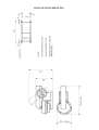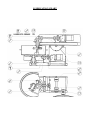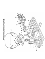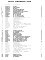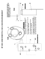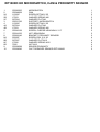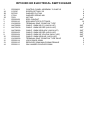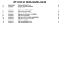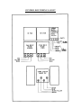
1
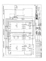
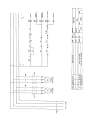
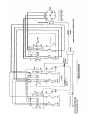
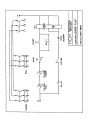
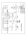
CUMFLOW RP100XD HD
ROTATING PAN MIXER
PARTS
&
OPERATION MANUAL
WINGET LIMITED
PO BOX 41
EDGEFOLD INDUSTRIAL ESTATE
PLODDER LANE
BOLTON
LANCS
BL4 OLS
Tel: ++44 (0)1204 854650
Fax: ++44 (0)1204 854663
[email protected]
[email protected]
[email protected]
www.winget.co.uk
INDEX
SECTION 1
GENERAL INFORMATION
1.1.
1.2.
1.3.
1.4
Company Details
Important Notice
Mixer Operational and Safety Requirements
Installation Drawing
SECTION 2
INSTALLATION AND OPERATING INSTRUCTIONS
2.1.
2.2.
2.3.
Pre Installation Notes
Installation Instructions
Operating Instructions
SECTION 3
TECHNICAL SPECIFICATION AND MAINTENANCE
3.1.
3.2.
3.3.
3.4.
Technical Specification
Shutdown Procedure and Maintenance
Lubrication
Gear Unit Maintenance
SECTION 4
MIXER SPARE PARTS
4.1.
4.2.
4.3.
4.4.
4.5.
4.6.
4.7.
4.8.
Mixing Pan & Drive
Mixing Star & Drive
Mixing Star Assembly
Mixing Star Lifting Arrangements
Layout of Guards
Micro Switch Cam & Proximity Switch
Electrical Switch Gear
Decals & Logos
SECTION 5
ANCILLIARY EQUIPMENT SPARE PARTS
5.1
5.2
Trolley
MoD Additional Parts
SECTION 6
ELECTRICAL SYSTEM
6.1
6.2
Electrical Instructions
Wiring Diagrams
SECTION 7
MISCELLEANEOUS
7.1
Noise Details
The contents of this handbook although correct at the time of publication, may be subject to
alteration by the manufacturers without notice and Winget Limited can accept no responsibility for
any errors or omissions contained within the following pages. Nor can we accept any liability
whatsoever arising from the use of this manual howsoever caused.
Winget Limited operate a policy of continuous product development. Therefore, some illustrations
or text within this publication may differ from your machine
Winget Limited can accept no responsibility for incorrectly supplied parts unless the machine serial
number, part number and a full description of the items required is given when the order is placed.
NOTE
Imperial fixings (bolts, setscrews, nuts, washers etc) have been progressively changed to Metric. If
in doubt as to whether you have a Metric or Imperial fixing please order the metric items listed, i.e.
bolt or setscrew and associated or flat and spring washers to replace the existing items
NOTE
Electrical cables particularly those with copper conductors suffer from a condition known as
‘relaxation’ which may cause wiring to work loose over a period of time, it is recommended
that the tightness of wiring connections and terminals are checked following the first month
in service.
OPERATING
AND
MAINTENANCE MANUAL
SECTION 1
GENERAL INFORMATION
RP100XD HD
COMPANY DETAILS AND GENERAL INFORMATION
For any spares or service work, please contact:Winget Limited
P.O. Box 41
Edgefold Industrial Estate
Plodder Lane
Bolton
Lancs
BL4 OLS
Telephone No:
Facsimile No:
‘E Mail’
++ 44 (0) 1204 854650
++ 44 (0) 1204 854663
[email protected]
[email protected]
[email protected]
ORDERING SPARES
To help us to complete your order promptly and correctly we need:• Machine type and serial number
• Description and quantity of parts required
• The full address to which the parts are to be sent
Winget Limited can accept no responsibility for incorrectly supplied parts unless the
machine serial number, part number and a full description of the items required is given
when the order is placed.
IMPORTANT NOTICE
The CUMFLOW RP100XD HD is a high performance mixer
The following precautions are necessary to obtain the best results and to avoid
damage to the MIXING STAR and PAN DRIVE
AGGREGATES
Strict control of graded aggregates must be maintained
Maximum size 19mm
Oversize lumps of aggregate or rogue materials must be prevented from
entering the Pan
MIXING STAR BLADES
They are to a special shape and material to prolong wear life. They should not
be modified in any way and only replaced with GENUINE ‘CROKER’ spares
obtained from WINGET LIMITED.
A daily check is advisable to ensure that the Blades/Wearing parts are secure
and undamaged.
MAXIMUM BATCH LOADS
UNDER NO CIRCUMSTANCES should the Maximum Batch Loads quoted
be exceeded nor should the mixer be stopped or re-started when there is a mix
in Pan
MIXING PAN
Ensure that the Mixing Pan is rotating concentrically and that the pan base is
Horizontal.
WARNING
THE MANUFACTURER ACCEPTS NO RESPOSIBILITY FOR ANY
DAMAGE OR FAILURE RESULTING FROM OPERATIONAL
MISUSE OR MALPRACTICE. ANY MODIFICATIONS TO THE
MACHINE WILL AFFECT ITS WORKING PARAMETERS AND
SAFETY FACTORS. REFER TO THE MANUFACTURERS BEFORE
FITTING ANY NON STANDARD EQUIPMENT OR PARTS.
THE MANUFACTURERS ACCEPT NO RESPONSIBILITY FOR ANY
MODIFICATIONS MADE AFTER THE MACHINE HAS LEFT THE
FACTORY, UNLESS PREVIOUSLY AGREED IN WRITING. THE
MANUFACTURERS WILL ACCEPT NO LIABILITY FOR DAMAGE
TO PROPERTY, PERSONNEL OR THE MACHINE IF FAILURE IS
BROUGHT ABOUT DUE TO SUCH MODIFICATIONS, OR THE
FITMENT OF SPURIOUS PARTS.
RP100XD HD
OPERATIONAL AND SAFETY
REQUIREMENTS
PRE-DELIVERY
1.1
Drive coupling alignments, pan and star meshing of pan rack and drive gear.
1.2
Operating clearances star blade to pan. Fixed blade to pan wall.
1.3
Correct oil level in gearboxes. All grease points charged. Gear teeth greased.
1.4
No load test. Correct rotations.
PRE INSTALLATION
2.1
Check consignment.
2.2
Offload equipment using certified lifting gear of suitable capacity, by a competent
person (see separate chart for nett weight).
INSTALLATION
3.1
Refer to contract arrangement and site instructions.
3.2
Mixer to be mounted on supports of adequate strength and rigidity to prevent undue
vibration when mixing and securely bolted.
3.3
Mixer frame to be level on structure, add packers as required.
3.4
Check that pan is correctly seated and that pan rack and drive gear are in correct
mesh.
ELECTRICAL SERVICES
4.1
Refer to wiring diagram in Ops Manual. All wiring to be undertaken by competant
electrician, it is recommended that the mains electrical supply is provided via an earth
leakage circuit breaker. NOTE: electrical cables particularly those with copper
conductors suffer from a condition known as ‘relaxation’ which may cause wiring to
work loose over a period of time, it is recommended that the tightness of wiring
connections and terminals are checked following the first month in service.
OPERATION
5.1
5.2
Correct oil level in the gearboxes.
Check the Mixing pan clear of loose nuts and bolts to prevent damage to fingers and
blades.
5.3
Check correct rotation – mixing star – anti clockwise; mixing pan – anti clockwise.
All when viewed from the top.
5.4
Blade operating clearances adjust in line with maintenance instructions.
5.5
Never exceed manufacturer’s maximum capacity as detailed in specification.
SHUTDOWN
6.1
Prior to any work being carried out mixer to be isolated and physically locked off
6.2
Follow the procedures detailed in your companies Heath and Safety Policy at
all times.
6.3
Ensure all storage bins containing materials to be mixed are isolated.
MAINTENANCE
7.1
Ensure that all maintenance is carried out in accordance with the Parts and
Operating manuals and proprietary manufacturer’s specific instruction.
7.2
Isolate electrical and other services to the mixer as section 6 above.
7.3
Service at recommended intervals.
7.4
Use Croker manufactured replacement parts available from WINGET
LIMITED.
7.5
Ensure all safety guards and interlocks are reinstated prior to operating mixer.
GENERAL
8.1
Under on circumstances should the Maximum Batch Loads be exceeded by
either weight and volume as stated in Technical Specification.
8.2
Mixer star blades to be checked daily for damage.
8.3
Pan rim and base wearing plates must be replaced before excessive wear causes
distortion.
8.4
Ensure mixing pan is rotating concentrically and pan base is rotating in
horizontal plane.
8.5
Mixer must not be stopped and started when there is mix in the pan.
8.6
Refer to the Contract Drawing for scope of supply and the Site instruction notes
outlining weights etc.
8.7
Refer to Method Statement when installation and commissioning is
responsibility of Croker.
Nett Weights Max (kgs)
9.1
RP50XD
788
RP100XD
814
RP100XD HD 900
RP200XD 1400
RP400XD 2000
RP550XD 2150
RP850XD 2600
RP1250XD 4840
RP1500XD 4980
RP3000XD
FP1000
FP1500
FP2000
7112
4040
4065
4100
9.2
Refer to technical specification for nett weights of ancillary equipment.
9.3
Refer to contract drawing for nett weights of ancillary equipment.
Miscellaneous
10.1 Noise. Measured in accordance with Directive 2000/14 EC:- The noise level did not
exceed 104dB(a)LWA
INSTALLATION DRAWING
OPERATING
AND
MAINTENANCE MANUAL
SECTION 2
INSTALLATION AND OPERATING
INSTRUCTIONS
PRE-INSTALLATION
On arrival of the equipment it is advisable to check that all packages listed on the
consignment note have been received.
The equipment must be offloaded using certified lifting gear of suitable capacity,
by a competent person.
An outline drawing and bolt hold plan is normally sent prior to the despatch of
the machine and will enable preparations to be made for the installation. With the
`picture` of what the machine will look like when it is assembled, the ancillary
equipment dismantled for transport can easily be identified.
INSTALLATION
Please refer to the contract arrangement and site instructions as applicable.
It is recommended that a concrete foundation (to take foundation bolts – not
supplied) should be provided for the machine to be mounted on
Before completing the installation, check that the main mixer frame is level with a
spirit level. Packings should be inserted as required under the main frame.
Check that the pan is seated and that the pan rack and drive gear are in mesh..
Also check that all the blade clearances are in line with the maintenance
instructions.
On connecting to the power supply, the wiring diagram must be referred to.
Note:- it is recommended that the mains electrical supply is taken via an
earth leakage circuit breaker.
The wiring is correctly connected to the motors when the pan and star drive
rotate as follows:• The mixing pan and mixing star rotate anti-clockwise when looking from the
top.
OPERATING THE MIXER
Prior to start up, the following points should be checked:1)
That there is oil in a)
b)
the pan drive gearbox
the star drive gearbox
2)
The mixing pan should be clear of loose nuts, bolts, spanners, etc as these
will damage the fingers and blades.
3)
Check that the blade clearances are correct and if necessary adjust, in line
with the maintenance instructions.
5)
To raise the mixing star out of the mixing pan, turn the hand wheel in a
clockwise direction until the arm is at 45’
6)
To lower, turn the hand wheel anti-clockwise and lower gently. The mixer
will automatically start if the mixing pan is in position. When the mixing
pan is removed the mixer cannot be operated as the proximity switches
need to sense the pan in position to complete the electrical circuit
7)
On completion of the mixing cycle the raising of the mixing star operates a
limit switch which automatically stops all moving parts
8)
The pan can then be removed by hand or with the special lifting trolley
available as an option
IMPORTANT:
After each mix the contents of the pan must be completely discharged.
At the end of each period of operation the mixing pan, mixing blades, and
fingers, must be washed down to prevent product setting on them and so
impairing the efficiency of the machine. NOTE:- isolate the electrical supply
before washing down the mixer and do not aim the water jet directly at
the electrical control panel or related switch gear or sensors
OPERATING THE MIXER
SAFETY NOTES
Never operate the mixer unless you have read and fully understand the contents
of the Operators Manual
Never operate the mixer whilst wearing loose fitting clothing
Never reach inside the Pan whilst it is rotating
Never operate any equipment unless you have received adequate training
Cement, certain other minerals and organic compounds can cause skin irritation
leading to Dermatitis. Always use Personal Protective Equipment i.e. gloves etc
to protect the skin from direct contact. If in any doubt about the materials being
used consult your employers COSHH manual
Wear Eye protection to protect your eyes from dust and liquid splashes
Do not attempt to remove the pan single handedly, obtain assistance, use the
Pan Trolley (if provided) or use suitable lifting equipment
Do not operate the mixer with any of the guards removed, safety devices or
interlocks disconnected. They are there to offer you some protection, ensure
they are correctly maintained
Carry out the daily maintenance before operating the mixer and report defects to
your supervisors
Oils, Greases and Lubricants are skin irritants and prolonged direct skin contact
can cause skin cancer. PPE or barrier creams should be used when carrying out
maintenance work, wash your hands on completion
Always dispose of waste oils and lubricants in a proper manner, it is illegal to
pour it down drains or bury it. Contact your local authority for a list of
authorised disposal sites
Always disconnect the power supply at the mains before carrying out any
maintenance work or cleaning the equipment down. Do not turn on the power
until everything has dried out
Do not allow waste from the wash down process to enter the public drainage
system unless it has been properly filtered
Decals and Instruction Plates are attached to the equipment to warn against
hazards and assist in the safe operation of the equipment, if they become
damaged or defaced they must be replaced.
OPERATING INSTRUCTIONS FOUR WHEEL PAN
TROLLEY
The Four-Wheel Pan Trolley is designed to allow the safe and speedy removal
and transportation of the pan and mixed materials to wherever they may be
required within the plant. The following instructions should be followed to
ensure the Four Trolley is used safely and correctly.
1) It is recommended that the Trolley be used only on firm level ground.
2) On no account should the laden Trolley be left unattended on anything other
than a level surface unless the castors are securely chocked.
3) The area around the mixer should be kept free from any build up of waste
material.
4) Ensue the Pan Lifting Lugs and Hoop attached to the pan are in good
condition, secure and free from any build up of waste material.
5) Position the Trolley in front of the mixer so that the wheels are equally
spaced to each side of the mainframe/chassis.
6) Fully raise the Mixing Star by means of the handwheel and allow the pan to
come to a complete stop. Manually rotate the pan until two of the Pan Lifting
Lugs are at right angles to the mainframe/chassis. This will allow the Trolley,
when correctly positioned below the pan to cleanly lift the pan clear of the rack.
7) Push the Trolley under the pan until the ‘V’ support arms on the Trolley are
aligned below the Pan Lifting Lugs, brace the Trolley by placing a foot in the
rear centre of lower fixed frame and pull back on the handle until the ‘V’
supports are engaged with the Pan Lifting Lugs, continue pulling back on the
handle until it abuts the stops, at which point the pan will be clear of the rack.
Manoeuvre both pan and Trolley clear of the mixer. The Trolley complete with
the pan can now be carefully pushed or pulled to wherever the mixed material
is required. Be aware of the increased inertia inherent in the combined weight
of the Trolley, Pan and Material.
8) Before tipping the pan to discharge the material it is recommended that the
handle is moved fully forward to lower the upper moving frame of the Trolley
firmly onto the lower fixed frame. When the material has been discharged the
trolley can be braced as described above, the handle pulled backwards against
the stops and the pan transported back to mixer where the pan can be easily and
quickly positioned over the rack and lowered into place.
9) On no account must attempts be made to engage the trolley with the mixer
mainframe/chassis unless the Star Drive is raised and the rack stationary.
10) Do not ‘swing’ on the Trolley Handles, doing so may cause the Trolley to
become unstable and it may tip backwards especially if the pan is empty
causing injury to either yourself or nearby persons.
OPERATING
AND
MAINTENANCE MANUAL
SECTION 3
TECHNICAL SPECIFICATION
AND MAINTENANCE
TECHNICAL SPECIFICATION OF
CUMFLOW RP100XD HD
Maximum Batch Capacity
CAPACITIES:
by Weight 200 kgs
by Volume 140 litres
Batch capacity and outputs will vary with material densities.
FEED MATERIAL:
Maximum Size
MIXER FRAME:
Strongly constructed from welded Steel Channel
MIXING PAN:
Steel Base Pan removed by hand or with the aid of a special
trolley.
MIXING STAR:
Two spring mounted mixing star blades and fixed scraper blade
MIXING STAR
CONTROLS
762mm(30’’) diameter handwheel raises mixing star clear of the
pan
Mixing pan drive 2.2kw totally enclosed geared electric motor to
suit 3 phase, 50 cycles, 380/420 volts a/c supply. Mixing star
drive 3.0kw totally enclosed geared electric motor to suit 3 phase,
50 cycles, 380/420 volts a/c supply
POWER UNITS:
ELECTRICAL
CONTROLS
19 mm
Direct on line starter controls both motors. Automatic safety
control switch operates when mixing star is raised out of
the pan with proximity switch to sense pan position
GUARDING
All gears are guarded to comply with the relevant PUWER and
Supply of Machinery Safety Regulations
SPEEDS
Speed of Pan
Speed of Star
16 rpm
74 rpm
WEIGHTS (UNLADEN)
900 kg
Weight of additional pan
95kg
MAINTENANCE OF MIXER
IMPORTANT NOTE:
Ensure that all maintenance is carried out in accordance with the Parts and Operating Manual
and Proprietary Manufacturer’s specific instruction.
PROCEDURE
1
ISOLATE ELECTRICAL AND OTHER SERVICES TO THE MIXER (see separate
section).
2
Service at recommended intervals.
3
Use Croker manufactured replacement parts available from WINGET LIMITED.
4
Ensure all safety guards and interlocks are reinstated prior to operating the mixer.
5
Main items of wear (see Section 4).
A)
B)
Star Blades
Fixed Blade
Access to mixing pan internals is via the safety interlocks. Each of the above are bolted
components and are replaced by simple method and usually achieved in situ without
dismantling other components.
C)
Other items prone to less wear are star blade fingers and mixing star. Each can
be replaced again in situ but pan covers may require removal to provide the
necessary access.
MAINTENANCE AND LUBRICATION
NOTE:
ALWAYS ENSURE APPARATUS IS ISOLATED FROM MAINS SUPPLY BEFORE
COMMENCING MAINTENANCE. IF NECESSARY A ‘PERMIT TO WORK’ SHOULD BE
OBTAINED
DAILY:
Charge the grease points using Total EP2 Grease (or equivalent)
WEEKLY
Lubricate
Racks
Pinions
Apply Open Gear Lubricant (or equivalent)
Apply Open Gear Lubricant ( or equivalent)
Inspect and top-up if necessary.
1.
2.
Star Gear Box
Pan Drive Gear Box
Use Total Carter EP460 3.5 litres cap
Use Total Carter EP460 3.5 litres cap
INSPECT AND ADJUST-MONTHLY
1.
Pan Gear and Pinion, grease with Open Gear Lubricant (or equivalent), as required.
2.
Adjust Star Blades, Fixed Blades and Discharge Blade to the following settings, also
make sure that Blade Fingers are free in their bearings and that the springs are clear of
obstruction.
3.
Star Drive Bevel Pinions, remove cover and grease pinions with Open Gear Lubricant
or equivalent as required. Check retaining grub screws and keys are tight.
MIXING BLADE
3mm clear of pan base. Adjust by moving the blade up or down its
finger.
FIXED BLADES
6mm clear of pan base with the leading edge just touching the pan
side. Adjust by moving the blade up or down its finger.
MAINTENANCE FOR GEAR UNITS
MAINTENANCE OF THE MOTORS
The surface of the housing as well as the cover lattice of the fan bonnet should be kept
clean in order not to endanger the cooling of the motor with dust and dirt.
Although the bearings of the motor have life time lubrication, the oil in the gearbox of a
new unit should be drained after the first 500 hours of operation and the case
thoroughly flushed with a light flushing oil before refilling with fresh oil to the correct
specification
LUBRICATION CHART
OPERATING
AND
MAINTENANCE MANUAL
SECTION 4
MIXER SPARE PARTS
RP100XD HD MIXING PAN & DRIVE
RP100XD HD MIXING PAN & DRIVE
1
3
4
5
6
7
7A
7B
8
9
10
11
12
12A
13
13A
13B
13C
14
14A
15
16
16A
16B
16C
17
17A
17B
17C
18
19
20
20A
21
22
23
23A
23B
23C
24
26
26A
27
29
30
32
32A
32B
32C
32D
CR549026
CR210136
CR520179
CR560006
CR150153
CR210137
333104020
176S01
CR210092
CR630047
11S06F
CR530477
68S05C
17S05
8S06H
61S06
267S09
105S07
CR320021
CR320023
CR460022
CR150925
176S01
7S06
11S06P
8S05J
61S05
267S07
105S05
CR520177
CR329015
79S05F
253S05
CR230042
CR239018
8S05G
61S05
267S07
105S05
CR329049
CR229061
V2005269
CR549006
555114904
CR269148
CR26100661
8S06F
267S09
105S07
61S06
PAN MIXING HD
PAN RACK
CONICAL SHAFT
FELT SEAL
CONICAL SHAFT BEARING
PAN CONICAL SUPPORT
NIPPLE GREASE 1/4 BSP STRAIGHT
COVER NIPPLE GREASE
CONICAL END CAP
KEY CAP WASHER
KEY CAP BOLT M16 X 40
KEY CAP LOCKING PLATE
LOCKING PLATE CAPSCREW M10 X 20
WASHER SPRING M10
CONICAL BOLT M16 X 60
NUT BINX M16
WASHER FLAT M16
WASHER TAPER M16
BEVEL PINION KEY, GIB HEAD 1/2 X 3/8 X4
ALTERNATIVE 1/2 X 7/16 X6 CUT TO SIZE
BEVEL PINION
BEVEL PINION SHAFT BEARING
COVER NIPPLE GREASE
NUT M16
SCREW SET M16 X 80
BOLT BEARING M12 X 65
NUT BINX M12
WASHER FLAT M12
WASHER TAPER M12
BEVEL PINION SHAFT
KEY FEATHER COUPLING, DRIVEN HALF
BOLT, RIGID COUPLING 1/2 BSW X 2''
NUT, RIGID COUPLING 1/2'' BSW
DRIVEN HALF, RIGID COUPLING
DRIVING HALF, RIGID COUPLING
BOLT GEAR UNIT M12 X 55
NUT BINX M12
WASHER FLAT M12
WASHER TAPER M12
KEY FEATHER COUPLING, DRIVING HALF
GEAR MOTOR UNIT, PAN DRIVE
PLUG OIL LEVEL CLEAR
SHIM PACK BEARING (4 SHIMS PER SET)
SHIM SET, GEARED MOTOR UNIT
CHASSIS FRAME HD
BEAM LIFTING (NOT ILLUSTRATED)
BOLT M16 X 50
WASHER FLAT M16
WASHER TAPER M16
NUT BINX M16
1
1
1
2
2
1
1
1
1
1
1
1
1
1
4
4
4
4
1
1
1
1
1
2
2
2
2
2
2
1
1
3
3
1
4
4
4
4
1
1
1
1
A/R
1
1
2
2
2
2
RP100XD HD MIXING PAN & DRIVE
(2)
33
33A
33B
CR640003
10S05
CR241587
EYE LIFTING
WASHER FLAT 1/2"
NUT 5/8" BSW NYLOC
4
4
4
RP100XD HD STAR DRIVE ASSEMBLY
RP100XD HD STAR DRIVE ASSEMBLY
1
1A
1B
3
3A
3B
3C
4
4A
4B
5
6
6A
6B
7
7A
7B
7C
7D
8
8A
8B
8C
8D
8E
9
9A
10
10A
10B
11
12
13
14
14A
15
16
17
21
23
23A
23B
23C
24
24A
24B
24C
25
25A
25B
25C
26
CR229062
555114904
V2005269
CR239019
CR239030
CR239028
CR230047
CR230044
57S05J1
CR329000
CR329046
CR520113
CR529015
57S05D2
CR159006
176S01
CR549006
11S06P
7S06
CR460024
57S05D2
555116600
11S04D
17S05
267S06
CR329046
CR329093
CR210139
333104020
176S01
CR529011
CR529012
CR529013
8S02C
17S03
CR150149
CR569008
CR569007
CR529014
8S06G
267S09
17S08
7S06
8S05M
267S07
105S05
61S05
8S05D
61S05
267S07
105S05
CR269150
MOTOR GEAR UNIT STAR DRIVE
SHIM GEAR MOTOR UNIT
PLUG OIL LEVEL CLEAR
COUPLING FLEXIBLE DRIVING HALF
BOLTS & NUTS FOR FLEXIBLE COUPLING
RUBBER BUSH FOR FLEXIBLE COUPLING
BOLT, NUT & BUSH ASSEMBLY FOR FLEXIBLE COUPLING
COUPLING FLEXIBLE DRIVEN HALF
SCREW GRUB COUPLING M8 X 30 CUP POINT
KEY, DRIVING HALF FLEXIBLE COUPLING
KEY, DRIVEN HALF FLEXIBLE COUPLING
SHAFT TOP
BEVEL PINION LOCKING COLLAR
SCREW GRUB
BEARING ASSEMBLY TOP SHAFT
COVER GREASE NIPPLE
SHIM PACK BEARINGS (4 SHIMS PER SET)
SCREW SET M16 X 80
NUT M16
GEAR BEVEL
GRUB SCREW M8
PLATE GEAR RETAINING
SCREW SET M10 X 30
WASHER SPRING M10
WASHER FLAT M10
KEY FEATHER BEVEL GEAR HORIZONTAL 1/2X5/16X2''
KEY FEATHER BEVEL GEAR VERTICAL 1/2X5/16X3/4''
SUPPORT CONICAL STAR
NIPPLE GREASE 1/4 BSP STRAIGHT
COVER NIPPLE GREASE
SHAFT STAR
UPPER LIP SEAL CARRIER
LOWER LIP SEAL CARRIER
BOLTS CARRIER M6 X 35
WASHER SPRING M6
BEARINGS STAR SHAFT
SEAL LIP UPPER
SEAL LIP LOWER
SPACER COLLAR STAR
BOLTS STAR CONICAL M16 X 55
WASHER FLAT M16
WASHER SPRING M16
NUT PLAIN M16
BOLTS TOP SHAFT BEARINGS M12 X 80
WASHER FLAT M12
WASHER TAPER M12
NUT BINX M12
BOLTS GEAR MOTOR UNIT M12 X 40
NUT BINX M12
WASHER FLAT M12
WASHER TAPER M12
STAR ARM CHASSIS/FRAME HD
1
A/R
1
1
6
6
6
1
1
1
1
1
1
2
2
2
2
4
4
2
6
2
2
2
2
1
1
1
2
2
1
1
1
8
8
2
1
1
1
4
8
4
4
4
4
4
4
4
4
4
4
1
RP100XD HD MIXING STAR ASSEMBLY
RP100XD HD MIXING STAR ASSEMBLY
14
14A
14B
17
18
19
19
19A
19B
19C
19D
20
21
21A
22
22A
22B
22C
26
26A
28
28A
28B
29
31
32
33
33A
33B
34
34A
35
35A
35B
36
36A
36B
36C
37
37A
37B
38
CR529020
11S05B
17S06
CR210140
CR329053
CR757244
CR219009C
CR219009P
CR219009SS
CR219009SP
CR219009SC
CR330061
11S05K
7S05
8S05J
267S07
17S06
7S05
CR260390
CR269149
CR210142
333104020
176S01
CR260415
CR539157
CR539158
CR639004
10S31
CR289002
8S04J
61S04
8S06L
17S08
267S08
52S05H
267S07
17S06
7S05
52S04K
17S05
7S04
CR330022
KEY CAP
SCREW SET M12 X 20
WASHER SPRING M12
STAR MIXING
KEY FEATHER MIXING STAR
BLADE STAR CAST, OBSOLETE USE ITEM 19 BELOW
BLADE STAR CAST, RIBBED
BLADE STAR POLYUREATHANE, RIBBED
BLADE STAR STAINLESS STEEL, RIBBED
BLADE STAR POLYUREATHANE, NO RIBS, SMOOTH
BLADE STAR CAST, NO RIBS, SMOOTH FINISH
SPRING COMPRESSION STAR BLADE
BOLT ADJUSTING BLADE FINGER M12 X 70
NUT M12
BOLT STAR BLADE M12 X 65
WASHER FLAT M12
WASHER SPRING M12
NUT M12
FINGER STAR BLADE
EXTENSION STAR BLADE FINGER (NOT ILLUSTRATED)
BRACKET FIXED BLADE
NIPPLE GREASE 1/4 BSP STRAIGHT
COVER NIPPLE GREASE
FINGER FIXED BLADE
BLADE FIXED HD
ANGLE BRACKET, BLADE FIXED
COLLAR SPACER
WASHER FLAT
GREASE NIPPLE 1/4 BSP 90' ANGLED
BOLT, COLLAR M10 X 65
NUT BINX M10
BOLT M16 X 65
WASHER, SPRING M16
WASHER FLAT M16
BOLT SHORT, FIXED BLADE M12 X 40
WASHER FLAT M12
WASHER SPRING M12
NUT M12
BOLT LONG, FIXED BLADE ANGLE BRACKET M10 X 50
WASHER, SPRING M10
NUT M10
SPRING FIXED BLADE
1
1
1
1
1
2
2
2
2
2
2
2
4
6
10
6
6
2
2
1
1
1
1
1
1
3
AR
2
3
3
2
2
2
2
4
4
4
2
2
2
1
RP100XD HD MIXING STAR LIFTING ARRANGEMENT
RP100XD HD MIXING STAR LIFTING ARRANGEMENT
1
2
2A
2B
3
5
5A
6
7
8
9
10
10A
11
11A
12
12A
13
14
14A
15
16
17
18
18A
19
19A
19C
20
20A
20B
21
21A
21B
21C
22
CR520175
CR190017
333104020
176S01
CR549025
CR630383
CR249098
CR260394
CR549009
CR520176
CR190046
CR360007
57S05D2
CR639000
CR249000
CR349005
CR249000
CR329050
CR200131
134104002
CR200134
CR200072
CR329046
CR289003
176S01
8S06N
267S08
61S06
8S05E
267S07
61S05
52S05G
17S06
7S05
CR220505
CR329047
PIVOT SHAFT
PIVOT SHAFT BEARING
NIPPLE GREASE 1/4 BSP STRAIGHT
COVER NIPPLE GREASE
SPACER, BEARING-HOUSING
BOSS, PLATE WHEEL
GRUB SCREW M10
PLATE, WHEEL
CAM, MICROSWITCH (SEE CAM & MICROSWITCH)
SHAFT, HANDWHEEL
BEARING, HANDWHEEL SHAFT
HANDWHEEL
SCREW GRUB (NOT ILLUSTRATED)
COLLAR, HANDWHEEL SHAFT
GRUB SCREW M6
PINION, CHAIN
GRUB SCREW M6
KEY, HANDWHEEL
CHAIN
LINK SPLIT CHAIN
BOLT & BLOCK, DRAW CHAIN
LINK ATTACHMENT, CHAIN END
KEY, BOSS PLATE WHEEL
NIPPLE GREASE1/4 BSP STRAIGHT
COVER NIPPLE GREASE
BOLTS, PIVOT SHAFT M16 X 90
WASHER FLAT M16
NUT BINX M16
BOLT, BEARINGS M12 X 45
WASHER FLAT M12
NUT BINX M12
BOLT, PLATEWHEEL M12 X 35
WASHER SPRING M12
NUT PLAIN M12
MICROSWITCH (NOT ILLUSTRATED)
KEY PARALLEL, CHAIN PINION
1
2
2
2
2
1
1
1
1
1
2
1
2
1
1
1
1
1
1
1
1
1
1
2
2
4
4
4
8
16
8
4
4
4
1
1
RP100XD HD COVERS & GUARDS
RP100XD HD COVERS & GUARDS
1
1
1A
1B
1D
1E
1F
1G
1H
1J
1K
1L
1N
1P
2
2
2A
2B
2C
3
3A
3B
3C
4
4A
4B
4C
4D
5
5A
5B
5C
6A
6B
6C
6D
7
7A
9
9A
9B
9C
9D
10
10A
10B
10C
11
11A
12
13
13A
CR53100636
CR53100805
11S05D
267S07
61S05
CR249505
11S01AA
11S01A
267S03
17S02
7S01
11S04B
267S06
61S04
CR540448
CR549188
11S04C
17S05
267S06
CR540441
11S05D
17S06
267S07
CR540447
11S04C
267S06
17S05
7S04
CR549027
267S06
17S05
7S04
11S02A
267S04
17S03
7S02
CR549027B
CR549027A
CR540442
11S04C
267S06
17S05
7S04
11S05D
267S07
17S06
7S05
8S06R
7S06
CR570019
CR269286
11S04B
HOUSING ASSEMBLY PAN DRIVE MOTOR
HOUSING ASSEMBLY PAN DRIVE MOTOR OPP HAND
SCREW SET M12 X 30
WASHER FLAT M12
NUT BINX M12
CATCH ASSEMBLY, DOOR HOUSING
SCREW SET M5 X 16
SCREW SET M5 X 20
WASHER FLAT M5
WASHER SPRING M5
NUT PLAIN M5
SCREW SET M10 X 20
WASHER FLAT M10
NUT BINX M10
GUARD, CHAIN GEAR
GUARD CHAIN GEAR, OPPOSITE HAND
SCREW SET M10 X 25
WASHER SPRING M10
WASHER FLAT M10
GUARD STAR DRIVE
SCREW SET M12 X 30
WASHER SPRING M12
WASHER FLAT M12
GUARD, PAN BASE AND GEVEL GEAR
SCREW SET M10 X 25
WASHER FLAT M10
WASHER SPRING M10
NUT PLAIN M10
DUST COVER ASSEMBLY
WASHER FLAT M10
WASHER SPRING M10
NUT PLAIN M10
SCREW SET M6 X 20
WASHER FLAT M6
WASHER SPRING M6
NUT PLAIN M6
COVER, DUST REAR
COVER, DUST FRONT
CLEAT, DUST COVER TO FRAME
SCREW SET M10 X 25 CLEAT TO DUST COVER
WASHER FLAT M10
WASHER SPRING M10
NUT PLAIN M10
SCREW SET M12 X 30 CLEAT TO FRAME
WASHER FLAT M12
WASHER SPRING M12
NUT PLAIN M12
SCREW SET STAR FRAME STOP M16 X 120
NUT PLAIN M16
SEAL RUBBER, FIXED BLADE ARM
GUARD, PAN RIM AND SIDE
SCREW SET M10 X 20
1
1
26
26
26
1
2
2
8
4
4
24
24
5
1
1
2
2
2
1
6
6
6
1
4
8
4
4
1
10
10
10
4
4
4
4
1
1
2
4
8
4
4
4
8
4
4
2
2
1
1
7
RP100XD HD COVERS & GUARDS
(2)
13B
13C
13D
15
15A
15B
15C
15D
267S06
17S05
11S02AA
CR549146
11S03C
267S05
17S04
7S03
WASHER FLAT M10
WASHER SPRING M10
SCREW SET M6 X 12
GUARD PINION SHAFT (NOT ILLUS) UP TO S/No 6019
SCREW SET M8 X 25 UP TO S/No 6019
WASHER FLAT M8 UP TO S/No 6019
WASHER SPRING M8 UP TO S/No 6019
NUT PLAIN M8 UP TO S/No 6019
7
7
2
1
4
4
4
4
BLACK
RED
Check position of Terminal Box on Motor BEFORE
CUTTING CONDUIT, if on top of Motor use 470mm x 2
to feed from motor to housing through coupling and
down to R/H side upper entry point on Control Panel
Top Motor (Star Drive) to entry point through
housing:- CONDUIT 680MM LONG
Sensor nearest to Control Panel to lower side entry
in panel:- CONDUIT 540MM LONG
Sensor furthest away from Control Panel to upper
side entry in panel:- CONDUIT 730MM LONG
CONDUIT LENGTHS
ADJUST PROXIMITY SWITCHES SO GAP
BETWEEN PAN AND SWITCH IS 1MM-10MM
MINIMUM. IF PAN STOPS OR FAILS TO
START CHECK ADJUSTMENT
RP100XD HD MICROSWITCH, CAM & SENSOR ARRANGEMENT
RP100XD HD MICROSWITCH, CAM & PROXIMITY SENSOR
1
2
2A
2B
2C
3
4
4A
4B
6
7
8
8A
8B
8C
8D
9
10
CR220505
CR549009
11S02C
17S03
267S04
CR531793
11S02C
267S04
17S03
CR243129
CR241632
CR269146
52S05F
267S07
17S06
7S05
CR229098
CR229090
MICROSWITCH
CAM
SCREW SET M6 X 25
WASHER SPRING M6
WASHER FLAT M6
SUPPORT, MICROSWITCH
SCREW SET M6 X 25
WASHER FLAT M6
WASHER SPRING M6
SCREW, CHEESE HEAD 4BA X 1.5"
NUT, BRASS 4BA
BRACKET, PROXIMITY SENSOR
SCREW CSK 12 X 30
WASHER FLAT M12
WASHER SPRING M12
NUT M12
SENSOR PROXIMITY
CAP THREADED SENSOR RETAINING
1
1
2
2
2
1
3
6
3
2
2
2
4
4
4
4
2
2
RP100XD HD ELECTRICAL SWITCH GEAR
1
1A
1B
1C
1D
2
3
4
5
6
7
8
9
10
11
12
13
14
CR229063
11S03C
267S05
17S04
7S03
CR229109
CR229110
191902200
144799000
144700100
144798000
CR229103
CR229104
CR229105
191902200
CR229114
CR229115
CR229111
CONTROL PANEL ASSEMBLY C/W KEYS
SCREW SET M8 X 30
WASHER FLAT M8
WASHER SPRING M8
NUT M8
SP20 CONDUIT
SP20/M20/TYPE B FITTINGS
TERMINAL RING 'CRIMP ON TYPE'
CABLE 1.5MM SQ G/Y (6491X H07)
CABLE 1.5MM SQ RED (6491X H07)
CABLE 1.5MM SQ BLACK (6491X H07)
CABLE 2.5MM SQ RED (6491X H07)
CABLE 2.5MM SQ YELLOW (6491X H07)
CABLE 2.5MM SQ BLUE (6491X H07)
TERMINAL RING 'CRIMP ON TYPE' BLUE
LOCK RINGS 20MM
REDUCER 25MM MALE/20MM FEMALE
GALVANISED COUPLER 25MM
1
4
8
4
4
4MT
12
2
3MT
3MT
3MT
2MT
2MT
2MT
6
3
2
1
RP100XD HD DECALS AND LOGOS
1
CROKER CUMFLOW RP100XD HD
9
2
10
4
5
11
6
12
7
13
8
RP100XD HD DECALS AND LOGOS
1
2
3
4
5
6
7
8
9
10
11
12
13
CR85100807
V2003037
101S05D
V2003039
V2003665
V2003598
V2004307
V2004223
V2004229
V2004744
504694600
V2004130
V2003575
DECAL RP100XD HD
PLATE SERIAL NUMBER
RIVET POP
DECAL 'WINGET' MEDIUM
DECAL SLING POINT
DECAL BRITISH MADE
DECAL ELECTRICAL HAZARD
DECAL 'CE' MARK
DECAL OPERATORS HANDBOOK
DECAL EYE PROTECTION
DECAL SAFETY
DECAL NOISE 80 LPA
DECAL NOISE 105 LWA
2
1
4
2
4
2
2
1
2
2
1
1
1
OPERATING
AND
MAINTENANCE MANUAL
SECTION 5
ANCILLARY EQUIPMENT
SPARE PARTS
PAGE INTENTIONALLY BLANK
RP100XD HD FOUR WHEEL PAN TROLLEY
FROM MARCH 2001 ONWARDS
1
1A
2
3
4
4A
5
6
7
8
9
10
11
12
13
14
15
16
17
18
19
CR26100858
CR47100860
11S04G
7S04
CR26100857
CR47100861
CR26100850
59S11
267S09
CR53100849
59S11
267S09
CR53100852
11S03C
17S04
267S05
11S03B
17S04
CR53100846
8S03E
61S03
FRAME LOWER
INSERT BLANKING 60 X 40
STOP SCREWS M10 X 45
NUT M10
FRAME UPPER
INSERT BLANKING 50 X 25
PIVOT BAR FRONT
NUT NYLOC M16
WASHER FLAT M16
PIVOT BAR REAR C/W HANDLE CARRIERS
NUT NYLOC M16
WASHER FLAT M16
PLATE PICKUP, PAN SUPPORT
SCREW SET UPPER M8 x 25
WASHER SPRING M8
WASHER FLAT M8
SCREW SET LOWER M8 x 20
WASHER SPRING M8
HANDLE TROLLEY
BOLT HANDLE RETAINING M8 x 45
NUT BINX M8
1
2
2
4
1
2
2
4
4
2
4
4
2
4
4
4
4
4
1
2
2
20
CR449001
CASTOR SWIVEL FRONT
INDIVIDUAL WHEEL ITEMS AVAILABLE AS FOLLOWS
20A
CR449002
WHEEL ASSEMBLY C/W BEARING
20B
CR449005
WHEEL CENTRE BUSH/SPACER
20C
11S05P
BOLT M12 x 80
20D
61S05
NUT BINX M12
1
1
1
1
21
22
23
24
8
8
8
8
11S04D
267S06
17S05
7S04
BOLT CASTOR RETAINING M10 x 30
WASHER FLAT M10
WASHER SPRING M10
NUT M10
2
25
CR449000
CASTOR FIXED REAR
INDIVIDUAL WHEEL ITEMS AVAILABLE AS FOLLOWS
25A
CR449002
WHEEL ASSEMBLY C/W BEARING
25B
CR449005
WHEEL CENTRE BUSH/SPACER
25C
11S05P
BOLT M12 x 80
25D
61S05
NUT BINX M12
1
1
1
1
26
27
28
29
30
8
8
8
8
2
11S04D
267S06
17S05
7S04
V2004636
BOLT CASTOR RETAINING M10 x 30
WASHER FLAT M10
WASHER SPRING M10
NUT M10
DECAL WINGET SMALL
2
RP100XD HD ADDITIONAL PARTS REQUIREMENT MoD
ADDITIONAL PARTS LISTED BELOW ARE NOT ILLUSTRATED
1
2
V2005120
101S05D
PLATE - NOMENCLATURE/INSCRIPTION
RIVET POP
1
4
3
4
5
6
7
V2005132
CR54100774
11S04B
17S05
7S04
TOOL KIT
TOOL BOX
SCREW SET M10
WASHER SPRING M10
NUT M10
1
1
2
2
2
OPERATING
AND
MAINTENANCE MANUAL
SECTION 6
ELECTRICAL SYSTEM
CONTROL BOX WIRING LAYOUT
OPERATING
AND
MAINTENANCE MANUAL
SECTION 7
MISCELLANEOUS
7.1 NOISE DETAILS
Measured in accordance with Directive 2000/14 EC the noise did not exceed
104dB(a)LWA