1
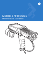
MC9090-G RFID Mobile
RFID User Guide Supplement
MC9090-G RFID User Guide Supplement
72E-89962-02
Rev A
March 2008
ii
MC9090-G RFID User Guide Supplement
© 2008 by Motorola, Inc. All rights reserved.
No part of this publication may be reproduced or used in any form, or by any electrical or mechanical means,
without permission in writing from Motorola. This includes electronic or mechanical means, such as
photocopying, recording, or information storage and retrieval systems. The material in this manual is subject to
change without notice.
The software is provided strictly on an “as is” basis. All software, including firmware, furnished to the user is on
a licensed basis. Motorola grants to the user a non-transferable and non-exclusive license to use each
software or firmware program delivered hereunder (licensed program). Except as noted below, such license
may not be assigned, sublicensed, or otherwise transferred by the user without prior written consent of
Motorola. No right to copy a licensed program in whole or in part is granted, except as permitted under
copyright law. The user shall not modify, merge, or incorporate any form or portion of a licensed program with
other program material, create a derivative work from a licensed program, or use a licensed program in a
network without written permission from Motorola. The user agrees to maintain Motorola’s copyright notice on
the licensed programs delivered hereunder, and to include the same on any authorized copies it makes, in
whole or in part. The user agrees not to decompile, disassemble, decode, or reverse engineer any licensed
program delivered to the user or any portion thereof.
Motorola reserves the right to make changes to any software or product to improve reliability, function, or
design.
Motorola does not assume any product liability arising out of, or in connection with, the application or use of
any product, circuit, or application described herein.
No license is granted, either expressly or by implication, estoppel, or otherwise under any Motorola, Inc.,
intellectual property rights. An implied license only exists for equipment, circuits, and subsystems contained in
Motorola products.
MOTOROLA and the Stylized M Logo and Symbol and the Symbol logo are registered in the US Patent &
Trademark Office. Bluetooth is a registered trademark of Bluetooth SIG. Microsoft, Windows and ActiveSync
are either registered trademarks or trademarks of Microsoft Corporation. All other product or service names
are the property of their respective owners.
Motorola, Inc.
One Motorola Plaza
Holtsville, New York 11742-1300
http://www.motorola.com
Patents
This product is covered by one or more of the patents listed on the web site: http://www.symbol.com/patents
iii
Revision History
Changes to the original manual are listed below:
Change
Date
Description
-01 Rev A
12/2006
Initial Release
-02 Rev A
3/2008
Added Laser Scanner
iv
MC9090-G RFID User Guide Supplement
Table of Contents
Patents.................................................................................................................................................. ii
Revision History.................................................................................................................................... iii
About This Guide
Introduction ...........................................................................................................................................
Documentation Set .........................................................................................................................
Configurations.......................................................................................................................................
Chapter Descriptions ............................................................................................................................
Notational Conventions.........................................................................................................................
Related Documents and Software ........................................................................................................
Service Information...............................................................................................................................
Support Information ........................................................................................................................
v
v
vi
vi
vii
vii
viii
viii
Chapter 1: Getting Started
Introduction ..........................................................................................................................................
MC909X User Guide ......................................................................................................................
Unpacking the Mobile Computer .........................................................................................................
Accessories .........................................................................................................................................
Getting Started .....................................................................................................................................
Installing and Removing the Main Battery ...........................................................................................
Installing the Main Battery ..............................................................................................................
Charging the Battery ............................................................................................................................
Charging the Main Battery and Memory Backup Battery ...............................................................
Charging the Main Battery .............................................................................................................
Charging Spare Batteries ....................................................................................................................
Removing the Main Battery ............................................................................................................
Starting the Mobile Computer ..............................................................................................................
Calibrating the Screen .........................................................................................................................
Checking Battery Status ......................................................................................................................
Battery Management ...........................................................................................................................
Battery Saving Tips ........................................................................................................................
1-1
1-1
1-2
1-3
1-4
1-4
1-4
1-5
1-5
1-6
1-7
1-7
1-8
1-8
1-9
1-9
1-9
vi
MC9090-G RFID User Guide Supplement
Stylus ...................................................................................................................................................
MC9090-G Strap ..................................................................................................................................
Changing the Power Settings ..............................................................................................................
Changing the Display Backlight Settings .............................................................................................
Changing the Keypad Backlight Settings .............................................................................................
Turning the Radios Off .........................................................................................................................
WLAN Radio on Windows Mobile 5.0 ............................................................................................
Bluetooth and WWAN Radios on Windows Mobile 5.0 ..................................................................
1-10
1-11
1-12
1-12
1-12
1-12
1-12
1-13
Chapter 2: Operating the MC9090-G RFID
Introduction ..........................................................................................................................................
Windows Mobile 5.0 Status Icons ........................................................................................................
Status Bar ......................................................................................................................................
Command Bar ................................................................................................................................
Speaker Icon ..................................................................................................................................
Battery Icon ....................................................................................................................................
Connectivity Icon ............................................................................................................................
Time Icon .......................................................................................................................................
Instant Message Icon .....................................................................................................................
E-Mail Icon .....................................................................................................................................
Multiple Notification Icon ................................................................................................................
Locking the Mobile Computer ..............................................................................................................
LED Indicators .....................................................................................................................................
Keypads ...............................................................................................................................................
53-Key Keypad for MC9090-G RFID .............................................................................................
Keypad Special Functions .............................................................................................................
Using the Power Button .......................................................................................................................
Using a Headset ..................................................................................................................................
Data Capture .......................................................................................................................................
Laser Scanning ..............................................................................................................................
Imaging ..........................................................................................................................................
Scanning Considerations ...............................................................................................................
Scanning Bar Codes ......................................................................................................................
Scan LED Indicator ........................................................................................................................
Reading RFID Tags .............................................................................................................................
Resetting the Mobile Computer ...........................................................................................................
Windows Mobile 5.0 Devices .........................................................................................................
Performing a Warm Boot .........................................................................................................
Performing a Cold Boot ............................................................................................................
Perform a Cold Boot: ..........................................................................................................
Waking the Mobile Computer .........................................................................................................
Bluetooth ..............................................................................................................................................
2-1
2-1
2-1
2-3
2-4
2-5
2-5
2-6
2-6
2-6
2-7
2-7
2-8
2-8
2-9
2-12
2-13
2-13
2-14
2-14
2-14
2-15
2-15
2-16
2-17
2-18
2-18
2-18
2-18
2-18
2-19
2-19
Table of Contents
vii
Chapter 3: Accessories
Introduction ..........................................................................................................................................
Keypads .........................................................................................................................................
Cradles ...........................................................................................................................................
Miscellaneous ................................................................................................................................
Snap-on Modules ...........................................................................................................................
Keypad .................................................................................................................................................
Keypad Removal ............................................................................................................................
Multi Media Card (MMC) / Secure Device (SD) Card ..........................................................................
3-1
3-1
3-1
3-2
3-2
3-3
3-3
3-4
Chapter 4: Maintenance & Troubleshooting
Introduction ..........................................................................................................................................
Maintaining the RFID reader ................................................................................................................
Accessories .........................................................................................................................................
Battery Safety Guidelines ....................................................................................................................
Troubleshooting ...................................................................................................................................
RFID Reader ..................................................................................................................................
4-1
4-1
4-2
4-2
4-3
4-3
Appendix A: Technical Specifications
Technical Specifications ...................................................................................................................... A-1
RFID Reader .................................................................................................................................. A-1
Accessory CAM and MSR Pin-Outs .................................................................................................... A-7
Appendix B: Keypad Special Keys
Introduction .......................................................................................................................................... B-1
Keypad ................................................................................................................................................. B-1
Appendix C: Regulatory
Introduction .......................................................................................................................................... C-1
Accessory Power Supply Regulatory Compliance ............................................................................... C-1
Index
viii
MC9090-G RFID User Guide Supplement
About This Guide
Introduction
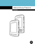
This MC9090-G RFID User Guide Supplement provides the unique user procedures for the MC9090-G RFID
mobile computers and accessories. This guide is intended as a supplement to the MC909X User Guide, P/N:
72E-72215-xx. Procedures common to the MC909X series of products are referenced to the MC909X Integrator
Guide.
NOTE
Screens and windows pictured in this guide are samples and may differ from actual screens.
Documentation Set
The documentation set for the MC9090-G RFID reader is divided into guides that provide information for specific
user needs.
• Microsoft Application Guide - describes how to use Microsoft developed applications.
• Symbol Application Guide - describes how to use Motorola developed applications.
• MC909X User Guide - describes how to use the MC909X mobile computers.
• MC9090-G RFID User Guide Supplement - describes how to use the MC9090-G RFID mobile computer.
• MC909X Integrator Guide - describes how to set up the MC909X mobile computers and the accessories.
• MC9090-G RFID Integrator Guide Supplement - describes how to set up the MC9090-G RFID mobile
computer and the accessories.
• SMDK Help File - provides API information for writing applications.
vi
MC9090-G RFID User Guide Supplement
Configurations
This guide covers the following configurations:
Configuration
MC9090-G
RFID
Radios
Display
WLAN: 802.11a/b/g Color
WPAN: Bluetooth
Memory
64 MB RAM
128 MB
Flash
Data
Capture
Operating
System
Laser Scan Windows
Imager
Mobile 5.0
RFID
Keypad
53-key RFID
Chapter Descriptions
Topics covered in this guide are as follows:
• Chapter 1, Getting Started, provides information on charging the mobile computer battery and resetting.
• Chapter 2, Operating the MC9090-G RFID, describes the MC9090-G RFID operating procedures.
• Chapter 3, Accessories, describes the accessories available for the mobile computer and how to use the
accessories.
• Chapter 4, Maintenance & Troubleshooting, includes instructions on cleaning and storing the mobile
computer, and provides troubleshooting solutions for potential problems during mobile computer operation.
• Appendix A, Technical Specifications, includes a table listing the technical specifications for the mobile
computer.
• Appendix B, Keypad Special Keys, includes a table listing the keypad special keys for the mobile computer.
• Appendix C, Regulatory, includes regulatory information for the mobile computer.
About This Guide
Notational Conventions
The following conventions are used in this document:
• “RFID Reader”, “reader” or “mobile computer” refers to the Motorola MC9090-G RFID reader.
• Italics are used to highlight the following:
• Chapters and sections in this guide
• Related documents
• Bold text is used to highlight the following:
• Dialog box, window and screen names
• Drop-down list and list box names
• Check box and radio button names
• Icons on a screen
• Key names on a keypad
• Button names on a screen.
• Bullets (•) indicate:
• Action items
• Lists of alternatives
• Lists of required steps that are not necessarily sequential.
• Sequential lists (e.g., those that describe step-by-step procedures) appear as numbered lists.
Related Documents and Software
The following documents provide more information about the MC9090-G RFID reader.
• MC9090-G RFID Quick Start Guide, p/n 72-89960-xx
• MC9090-G RFID Windows® Mobile® 5.0 Regulatory Guide, p/n 72-89961-xx
• MC9090-G RFID Integrator Guide Supplement, p/n 72-89963-xx
•
•
•
•
•
•
•
•
MC909X User Guide, p/n 72E-72215-xx
MC909X Integrator Guide, p/n 72E-72216-xx
Symbol Application Guide for Symbol Devices, p/n 72E-68901-xx
Microsoft Applications for Mobile and WinCE 5.0 User Guide, p/n 72E-78456-xx
Symbol Mobility Developer Kit (SMDK) Help File, p/n 72E-38880-03
Symbol Mobility Developer Kits, available at: http://support.symbol.com
Symbol Mobility Developer Kit for C, available at: http://support.symbol.com
ActiveSync software, available at: http://www.microsoft.com.
For the latest version of this guide and all guides, go to: http://support.symbol.com.
vii
viii
MC9090-G RFID User Guide Supplement
Service Information
If an equipment problem occurs, contact the appropriate regional Support Center for contact information. Before
calling, locate the model number and serial number.
Call the Support Center from a phone near the scanning equipment so that the service person can try to talk
through the problem. If the equipment is found to be working properly and the problem is symbol readability, the
Support Center will request samples of bar codes for analysis at our plant.
If the problem cannot be solved over the phone, the equipment may need to be returned for servicing. If that is
necessary, specific directions will be provided.
NOTE Motorola is not responsible for any damages incurred during shipment if the approved shipping container
is not used. Shipping the units improperly can possibly void the warranty.
Support Information
For service information, warranty information or technical assistance contact or call the Support Center. Contact
information is provided on the Motorola contact web site go to: http://www.support.symbol.com.
If the Motorola product was purchased from a Motorola Business Partner, contact that Business Partner for
service.
Chapter 1 Getting Started
Introduction
This chapter lists the accessories for the MC9090-G RFID mobile computer and explains how to install and charge
the batteries, replace the strap and start the mobile computer for the first time.
NOTE
This MC9090-G RFID User Guide Supplement is intended as a supplement to the MC909X User Guide,
P/N: 72E-72215-xx. Procedures common to the MC909X series of products are referenced to the
MC909X User Guide.
MC909X User Guide
The MC909X User Guide, P/N: 72E-72215-xx provides the following support information applicable to the MC9090-G
RFID mobile computer:
• Accessories; describes the accessories available for the mobile computers and how to set up power
connections and battery charging capabilities, where applicable.
• Operating the MC909X; explains how to use the mobile computer. This includes instructions for powering on
and resetting the mobile computer, entering and capturing data.
• Using Bluetooth; explains how to perform Bluetooth functionality on the mobile computer.
• Accessories; describes the accessories available for the mobile computer and how to use the accessories
with the mobile computer.
• Maintenance & Troubleshooting; includes instructions on cleaning and storing the mobile computer, and
provides troubleshooting solutions for potential problems during mobile computer operation.
1-2
MC9090-G RFID User Guide Supplement
Unpacking the Mobile Computer
Carefully remove all protective material from around the mobile computer and save the shipping container for later
storage and shipping.
Verify that you received all equipment listed below:
• Mobile computer
• Lithium-ion battery
• Strap, attached to the mobile computer
• Stylus, in the stylus silo
• Regulatory Guide
• Quick Start Guide (poster)
Inspect the equipment for damage. If you are missing any equipment or if you find any damaged equipment,
contact the Symbol Technologies Support Center immediately. See page viii for contact information.
Indicator LED Bar
Touch Screen
Microphone (Windows
Mobile 5.0 only)
Scan Button
Keypad
Headphone Jack
(Windows Mobile
5.0 only)
Power Button
Trigger
Handstrap
Figure 1-1 MC9090-G RFID Mobile Computer
Getting Started
Accessories
Table 1-1 lists the accessories available for the MC9090-G RFID.
Table 1-1 MC9090-G RFID Accessories
Accessory
Description
Cable Adapter Module
(CAM)
Snap-on required to connect the following cables to the mobile computer.
• AC line cord (country-specific) and power supply, charges the mobile
computer.
• Auto charge cable, charges the mobile computer using a vehicle’s
cigarette lighter.
• DEX cable, connects the mobile computer to a vending machine.
• Serial cable, adds serial communication capabilities.
• USB cable, adds USB communication capabilities.
• Printer cable, adds printer communication capabilities.
Four Slot Charge Only
Cradle
Charges the mobile computer main battery.
Four Slot Ethernet Cradle
Charges the mobile computer main battery and synchronizes the mobile
computer with a host computer through an Ethernet connection.
Four Slot Spare Battery
Charger
Charges up to four mobile computer spare batteries.
Magnetic Stripe Reader
(MSR)
Snaps on to the mobile computer and adds magstripe read capabilities.
Modem Module
Enables data communication between the mobile computer and a host
computer, remotely through the phone lines, and synchronizes information
between the mobile computer and a host computer.
Multimedia Card (MMC)
Provides secondary non-volatile storage.
Single Slot Serial/USB
Cradle
Charges the mobile computer main battery and a spare battery. It also
synchronizes the mobile computer with a host computer through either a serial
or a USB connection.
Software
Symbol Mobility Developer Kits available at: http://support.symbol.com.
Spare lithium-ion battery
Replacement battery.
Stylus
Performs pen functions.
Universal Battery Charger
Adapter
Adapts the UBC for use with the Series 9000 batteries.
Wall Mounting Bracket and
Shelf Slide
Use for wall mounting applications.
1-3
1-4
MC9090-G RFID User Guide Supplement
Getting Started
In order to start using the mobile computer for the first time:
• Install the main battery
• Charge the main battery and backup battery
• Start the mobile computer
• Configure the mobile computer
The main battery can be charged before or after it is installed. Use one of the spare battery chargers to charge the
main battery (out of the mobile computer), or one of the cradles to charge the main battery installed in the mobile
computer.
Installing and Removing the Main Battery
Installing the Main Battery
Before using the mobile computer, install a lithium-ion battery by sliding the battery into the mobile computer as
shown in Figure 1-2.
NOTE
Ensure the battery is fully inserted. Two audible clicks can be heard as the battery is fully inserted. A
partially inserted battery may result in unintentional data loss.
When a battery is fully inserted in a mobile computer for the first time, upon the mobile computer’s first power up,
the device boots and powers on automatically.
Figure 1-2 Installing the Main Battery
Getting Started
1-5
Charging the Battery
Charging the Main Battery and Memory Backup Battery
Before using the mobile computer for the first time, charge the main battery until the amber charge indicator light
remains lit (see Table 1-2 on page 1-6 for charge status indications). Charge time is less than four hours. The
mobile computer can be charged using a cradle, the CAM with a charging cable, or the MSR with the appropriate
power supply.
The mobile computer is equipped with a memory backup battery which automatically charges from the
fully-charged main battery. When the mobile computer is used for the first time, the backup battery requires
approximately 15 hours to fully charge. This is also true any time the backup battery is discharged, which occurs
when the main battery is removed for several hours. The backup battery retains data in memory for at least 30
minutes when the mobile computer's main battery is removed. When the mobile computer reaches a very low
battery state, the combination of main battery and backup battery retains data in memory for at least 72 hours.
NOTE
Do not remove the main battery within the first 15 hours of use. If the main battery is removed before the backup battery
is fully charged, data may be lost.
Use the following to charge batteries:
• Cradles: The mobile computer slips into the cradles for charging the battery in the mobile computer (and
spare batteries, where applicable).
- Single Slot Serial/USB Cradle.
- Four Slot Ethernet Cradle and Four Slot Charge Only Cradles.
• Accessories: The mobile computer’s snap-on accessories provide charging capability, when used with one of
the accessory charging cables.
- CAM
- MSR.
• Chargers: The mobile computer’s spare battery charging accessories are used to charge batteries that are
removed from the mobile computer.
- Single Slot Serial/USB Cradle
- Four Slot Spare Battery Charger
- Universal Battery Charger (UBC).
NOTE
To achieve the best battery life in mobile computers with multiple radios, turn off the radios that are not
being used. This can be accomplished via the SetDevicePower() API (refer to the SMDK Help File for
Symbol Mobile Computers) or via the Control Panel application (tap Start > 9000 Demo > Ctl Panel
icon).
1-6
MC9090-G RFID User Guide Supplement
Charging the Main Battery
Charge the main battery in the mobile computer using a cradle, the CAM with a charging cable, or the MSR with
the appropriate power supply.
1.
Ensure the accessory used to charge the main battery is connected to the appropriate power source (see
Chapter 3, Accessories for setup information).
2.
Insert the mobile computer into a cradle or attach the appropriate snap-on module.
3.
The mobile computer starts to charge automatically. The amber charge LED, in the Indicator LED Bar, lights to
show the charge status. See Table 1-2 for charging indications.
The main battery usually fully charges in less than four hours.
Table 1-2 Mobile Computer LED Charge Indicators
LED
Indication
Off
Mobile computer not in cradle or the mobile computer is not attached to the CAM or
MSR. Mobile computer not placed correctly. Charger is not powered.
Fast Blinking Amber
Error in charging; check placement of the mobile computer.
Slow Blinking Amber
Mobile computer is charging.
Solid Amber
Charging complete.
Getting Started
1-7
Charging Spare Batteries
Use the following three accessories to charge spare batteries:
• Single Slot Serial/USB Cradle
• Four Slot Spare Battery Charger
• UBC Adapter.
To charge a spare battery:
1.
Ensure the accessory used to charge the spare battery is connected to the appropriate power source (see
Chapter 3, Accessories for setup information).
2.
Insert the spare battery into the accessory’s spare battery charging slot with the charging contacts facing down
(over the charging pins) and gently press down on the battery to ensure proper contact.
3.
The battery starts to charge automatically. The amber charge LED on the accessory lights to show the charge
status. See Chapter 3, Accessories for charging indications for the accessory.
The battery usually fully charges in less than four hours.
Removing the Main Battery
To remove the main battery:
1.
Prior to removing the battery, press the red Power button to place the mobile computer in the suspend mode.
2.
Simultaneously press both primary battery releases. The battery partially ejects from the mobile computer.
3.
Pause 3-4 seconds while the mobile computer performs battery removal shutdown.
4.
Press the secondary battery release, on top of the battery, and slide the battery out of the mobile computer.
Primary Battery Releases
Secondary Battery
Release
Figure 1-3 Removing the Main Battery
1-8
MC9090-G RFID User Guide Supplement
Starting the Mobile Computer
Press the red Power button to turn on the mobile computer. If the mobile computer does not power on, perform a
cold boot. See the MC9090-G RFID Integrator Guide Supplement, p/n 72-89963-xx for cold boot procedures.
NOTE
When a battery is fully inserted in a mobile computer for the first time, upon the first power up, the device
boots and powers on automatically.
When the mobile computer is powered on for the first time, it initializes its system. The Symbol splash screen
(Figure 1-4) appears for a short period of time.
Figure 1-4 Symbol Splash Window
Calibrating the Screen
To calibrate the screen so the cursor on the touch screen aligns with the tip of the stylus:
1.
Using the stylus carefully press and briefly hold the tip of stylus on the center of each target that appears on the
screen.
NOTE
2.
To re-calibrate the screen at anytime, press the blue FUNC and ESC keys on the mobile computer to
launch the calibration screen application.
Repeat as the target moves around the screen or press ESC to cancel.
Getting Started
1-9
Checking Battery Status
To check whether the main battery or backup battery in the mobile computer is charged, tap Start - Settings System Tab - Power icon to display the Battery Status window.
To save battery power, set the mobile computer to turn off after a specified number of minutes.
To perform a cold boot:
1.
Press the primary battery release on the mobile computer to partially eject the battery from the mobile
computer.
2.
On an MC9090-G, while the battery is partially released, simultaneously press and release the trigger and the
Power button.
3.
Push the battery to fully re-insert it in the mobile computer. One audible click can be heard as the battery is fully
inserted.
4.
The mobile computer initializes.
Battery Management
Battery Saving Tips
• Leave the mobile computer connected to AC power at all times when not in use.
• Set the mobile computer to turn off after a short period of non-use.
• Set the display and keyboard backlight to turn off after a short period of non-use.
• Turn off all wireless radio activity when not in use.
• Power off the mobile computer when charging to charge at a faster rate.
1 - 10 MC9090-G RFID User Guide Supplement
Stylus
To remove the stylus, pull the stylus cord down and outward to remove the stylus.
Figure 1-5 Removing the Stylus
Use the mobile computer stylus for selecting items and entering information. The stylus functions as a mouse.
• Tap: Touch the screen once with the stylus to press option buttons and open menu items.
• Tap and Hold: Tap and hold the stylus on an item to see a list of actions available for that item. On the pop-up
menu that appears, tap the action to perform.
• Drag: Hold the stylus on the screen and drag across the screen to select text and images. Drag in a list to
select multiple items.
Getting Started 1 - 11
MC9090-G Strap
The strap may be moved to either the left or right side of the mobile computer to suit user preferences.
To reposition the strap:
1.
Disconnect the metal clip at the handle.
2.
Open strap loop and slide the handstrap through the loop.
3.
Slide the loop out of the connector post.
4.
Reverse the procedure to re-attach the strap. Two strap connectors are provided on the mobile computer’s
main body. The handstrap may be attached to either connector.
Strap Loop
Handstrap
Metal Clip
Figure 1-6 Reposition the Strap
1 - 12 MC9090-G RFID User Guide Supplement
Changing the Power Settings
To set the mobile computer to turn off after a short period of non-use:
1.
On devices with Windows Mobile 5.0, tap Start > Settings > System tab > Power icon > Advanced tab.
2.
Select the On battery power: Turn off device if not used for: check box and select a value from the drop-down list
box.
3.
Tap OK.
Changing the Display Backlight Settings
To change the display backlight settings in order to conserve more battery power:
1.
On devices with Windows Mobile 5.0, tap Start > Settings > System tab > Backlight icon > Battery Power tab.
2.
Select the On battery power: Disable backlight if not used for: check box and select a value from the drop-down
list box.
3.
Tap the Brightness tab.
4.
Tap the Disable backlight check box to completely turn off the display backlight.
5.
Use the slider to set the brightness of the backlight. Set it to a low value to save battery power.
6.
Tap OK.
Changing the Keypad Backlight Settings
To change the keypad backlight settings in order to conserve more battery power:
1.
Tap Start > Settings > System tab > Keylight icon > Battery Power tab.
2.
Select the On battery power: Disable keylight if not used for: check box and select a value from the drop-down
list box.
3.
Tap the Advanced tab.
4.
Tap the Disable keylight check box to completely turn off the display backlight.
5.
Tap OK.
Turning the Radios Off
WLAN Radio on Windows Mobile 5.0
To turn off the WLAN radio tap the Wireless Connection Status icon at the bottom of the Today screen and select
Disable Radio. A red X appears across the icon indicating that the radio is disabled (off).
Getting Started 1 - 13
Wireless Connection Status Icon
Figure 1-7 Wireless Connection Status Icon
To turn the radio back on, tap the Wireless Connection Status icon at the bottom of the Today screen and select
Enable Radio. The red X disappears from the icon indicating that the radio is enabled (on).
Bluetooth and WWAN Radios on Windows Mobile 5.0
NOTE
The Flight Mode feature only turns off the WWAN and Bluetooth radios. The WLAN radio must be turned
off separately.
To turn off the Bluetooth and WWAN radios, tap the Connectivity icon
(on non-WWAN devices) or the
Antenna/Signal icon
(on WWAN devices) and select Turn On Flight Mode.
NOTE
On the MC9090, it takes two to five seconds for the radio to shut down.
(on non-WWAN devices) or the
To turn on the Bluetooth and WWAN radios, tap the Connectivity icon
Antenna/Signal icon
(on WWAN devices) and select Turn Off Flight Mode.
NOTE
On the MC9090, wait 20 to 40 seconds for the radio to power on. During this time do not suspend the
mobile computer or remove the battery. If the mobile computer is suspended or the battery is removed,
warm boot the mobile computer.
The MC909X User Guide, P/N: 72E-72215-xx provides the Bluetooth support information applicable to the
MC9090-G RFID mobile computer.
1 - 14 MC9090-G RFID User Guide Supplement
Chapter 2 Operating the MC9090-G RFID
Introduction
This chapter explains the physical buttons, status icons and controls on the mobile computer, how to use the
mobile computer, including instructions for powering on and resetting the mobile computer, using the stylus and a
headset, entering information and scanning.
Windows Mobile 5.0 Status Icons
Status Bar
The Status Bar at the top of the window displays the current time, battery status and communication status.
Start Button
Status Icons
Volume Icon
Date/Time
Figure 2-1 Status Bar
Status icons are shown in the Status Bar to indicate present status of the mobile computer. Tapping each status
icon displays the corresponding dialog box the settings then be changed or adjusted. The status icons listed in
Table 2-1 on the Status Bar may be located at the top of the screen.
2-2
MC9090-G RFID User Guide Supplement
Table 2-1 Status Icons
Icon
Function
Description
Speaker
Turns all sounds on and off.
Battery
Backup battery is very low.
Main battery is charging.*
Main battery is low.
Main battery is very low.
Main battery is full.*
Connectivity
Connection is active.
GPRS available.
GPRS in use.
EGPRS available.
EGPRS in use.
Synchronization is occurring.
WWAN
Call missed.
Voice call.
Voice call in progress.
Calls are forwarded.
Call on hold.
Antenna/signal icon: wireless on/good signal.
Antenna/signal icon: wireless off.
Antenna/signal icon: no service or searching.
Roaming icon. Outside of the home area.
Missing SIM Card icon: SIM Card not installed or installed improperly.
Instant Message
Notification that one or more instant messages were received.
E-Mail
Notification that one or more e-mail messages were received.
Voice Mail
Notification that one or more voice messages were received.
Time and Next
Appointment
Displays current time in analog or digital format.
Multiple Notifications
There are more notification icons than can be displayed. Tap to display
remaining icons.
* Only appears in the Time and Next Appointment dialog box.
Operating the MC9090-G RFID
Command Bar
The icons listed in Table 2-2 on the Command Bar may be located at the bottom of the screen.
Status Icons
Figure 2-2 Command Bar
Table 2-2 Command Bar Icons
Icon
Description
Wireless connection status icon. Indicates WLAN signal strength and opens the Wireless
Applications menu.
The Bluetooth Enabled icon appears in the task tray and indicates that the Bluetooth radio is on.
The Bluetooth Disabled icon appears in the task tray and indicates that the Bluetooth radio is off.
The Bluetooth Communication icon appears in the task tray and indicates that the mobile computer
is communicating with another Bluetooth device.
The ActiveSync icon appears in the task tray and indicates an active connection between the mobile
computer and the development computer.
2-3
2-4
MC9090-G RFID User Guide Supplement
Speaker Icon
Adjust the system volume using the Speaker icon in the Status bar.
1.
Tap the Speaker icon. The Volume dialog box appears.
Figure 2-3 Volume Dialog Box
NOTE
When not in a call, the phone volume slider adjusts the volume of the ringer. When in a call, adjusts the
volume of the call audio.
2.
Tap and move the slide bar to adjust the volume.
3.
Select the On or Off radio button to turn the volume on or off.
NOTE
Use can also adjust the system volume using the Sounds & Notifications window or by pressing the
Blue key and 6 or the Blue key and 7.
Operating the MC9090-G RFID
2-5
Battery Icon
Battery icons display on the Title Bar when the main battery or backup battery power falls below a predetermined
level. A Battery dialog box also appears indicating the status of the main or backup battery.
Figure 2-4 Battery Status Dialog Box
View the battery status using the Power window.
Connectivity Icon
The Connectivity icon indicates the communication status of the terminal when it’s connecting to the internet or
host computer.
Figure 2-5 Connectivity Dialog Box
2-6
MC9090-G RFID User Guide Supplement
Time Icon
The Time icon displays the current time in a digital or analog format. To change the time format, tap and hold the
Time icon until a menu appears. Select the desired format.
Digital Clock
Analog Clock
Figure 2-6 Time Icon Format Menu
To display current date, time and appointments:
1.
Tap the Time icon to display the Time and Next Appointment dialog box.
Battery Status Icon
Upcoming Appointments
Current Date and Time
Figure 2-7 Time and Next Appointment Dialog Box
2.
The dialog box displays the current date and time, the battery status and any upcoming appointments in the
Calendar.
Instant Message Icon
The Instant Message icon provides a notification when MSN Messenger has received a new incoming message.
Figure 2-8 MSN Messenger Dialog Box
E-Mail Icon
The E-Mail icon provides a notification when an incoming e-mail is received.
Figure 2-9 New E-mail Messages Dialog Box
Operating the MC9090-G RFID
2-7
Multiple Notification Icon
The Multiple Notification icon appears when two or more message notifications occur. Tap the icon to display the
multiple notification icons.
Figure 2-10 Multiple Notifications Icon
Locking the Mobile Computer
Use the Device Lock feature to prevent use of the device. When locked, the mobile computer does not respond to
screen or keypad input. To lock the device, tap the Device unlocked icon. The icon changes to locked.
Figure 2-11 Device Locked/Unlocked Icons
To unlock the device and free it for use, tap Unlock.
Figure 2-12 Unlock Device Window
Tap Unlock on the Unlock Device window.
2-8
MC9090-G RFID User Guide Supplement
LED Indicators
The MC9090-G RFID has an LED Indicator Bar that contains LEDs that indicate scanning and charging status.
Table 2-3 describes the LED indications.
LED Indicator Bar
Figure 2-13 MC909X LEDs Indicator Bar
Table 2-3 Mobile Computer LED Indications
LED State
Indication
Solid Red
Laser enabled, scanning/imaging in process.
Solid Green
Successful decode/capture.
Slow Blinking Amber
Main battery in mobile computer is charging.
Fast Blinking Amber
Error in charging; check placement of the mobile computer.
Solid Amber
Main battery in mobile computer is fully charged.
NOTE
The RFID read enabled and successful RFID tag read indications are displayed on the screen, not on the
LED indicators.
Keypads
The mobile computer has the following modular keypad:
• 53-key keypad
The modular keypads can be removed in the field, as necessary. The MC909X User Guide, P/N: 72E-72215-xx
provides the keypad support information applicable to the MC9090-G RFID mobile computer.
Operating the MC9090-G RFID
2-9
53-Key Keypad for MC9090-G RFID
The 53-key keypad contains a Power button, application keys, scroll keys and function keys. The keypad is
color-coded to indicate the alternate function key (blue) values. Note that keypad functions can be changed by an
application so the mobile computer’s keypad may not function exactly as described. See Table 2-4 on page 2-10
for key and button descriptions and Table 2-5 on page 2-12 for the keypad’s special functions.
Figure 2-14 53-Key Keypad for MC9090-G RFID
2 - 10 MC9090-G RFID User Guide Supplement
Table 2-4 53-Key Descriptions
Key
Description
Power (red)
Turns the mobile computer on and off.
Performs a warm boot and a cold boot. See Windows Mobile 5.0 Devices on page
2-18 for information about performing a warm and cold boot.
Green/Red Dot
To use a key as an application key (APP key) on the keyboard, a new keyboard
remap table must be created and installed. However, the Green/Red dot keys can be
remapped as APP keys through the registry.
Create an XML Provisioning file with the following entries:
Characteristic type
=“HKEY_LOCAL_MACHINE\HARDWARE\DEVICEMAP\KEYBD”
Parm name = “GreenKeyOverride” value = “xx”, where xx is the new APP key code.
Parm name = “RedKeyOverride” value = “xx”, where xx is the new APP key code.
Refer to the MC909X Integrator Guide for instruction on updating the registry using
XML Provisioning.
This sends an APP key code, instead of their original key codes, when the green or
red dot key is pressed.
Scan (yellow)
Activates the scanner/imager in a scan enabled application.
Scroll Up and Down
Moves up and down from one item to another.
Increases/decreases specified values.
Scroll Left and Right
Moves left and right from one item to another.
Increases/decreases specified values.
ESC
Exits the current operation.
Alpha
Use the alpha keys for alphabetic characters.
SPACE/BKSP
Space and backspace functions.
Numeric/Application
Numeric value keys - can have applications assigned with function key(s).
The F6 and F7 keys cannot be remapped and are dedicated by the Operating
System to control volume level. When these keys are pressed, Shell.exe traps them
and displays the volume adjustment window. To get these keys to an application, call
GXOpenInput() at the beginning of the application and call GXCloseInput() at the
end of the application. This redirects all of the key events to an application, including
the F6 and F7 keys.
Operating the MC9090-G RFID 2 - 11
Table 2-4 53-Key Descriptions (Continued)
Key
Function (blue)
LED
Control
LED
Description
Press and release the blue function key to activate the keypad alternate functions
(shown on the keypad in blue). The
icon appears at the bottom of the screen on
Windows Mobile 5.0 devices. Press and release the blue function key again to return
to the normal keypad functions.
Press and release the CTRL key to activate the keypad alternate CTRL functions.
The
icon appears at the bottom of the screen on Windows Mobile 5.0 devices.
Press the Blue key followed by the CTRL key to activate the keypad alternate ALT
functions. The
devices.
Shift
icon appears at the bottom of the screen on Windows Mobile 5.0
Press and release the SHIFT key to activate the keypad alternate SHIFT functions.
The
icon appears at the bottom of the screen on Windows Mobile 5.0 devices.
Press and release the SHIFT key again to return to the normal keypad functions.
Period/Decimal Point
Produces a period for alpha entries and a decimal point for numeric entries.
Star
Produces an asterisk.
Enter
Executes a selected item or function. The default behavior of the ENT (Enter) key
sends an extra character, which causes a Microsoft Word or Notes application to
exit. To make the applications work properly, create an XML Provisioning file with the
following entries:
Characteristic type
=”HKEY_LOCAL_MACHINE\HARDWARE\DEVICEMAP\KEYBD”
Para name = “SpecialEnterTabKey” value = 0
Refer to the MC909X Integrator Guide for instruction on updating the registry using
XML Provisioning.
2 - 12 MC9090-G RFID User Guide Supplement
Keypad Special Functions
The keypad special functions are color coded on the keypads. For example, on the 53-key keypad, the display
backlight icon is blue indicating that the blue function key must be selected first to access the display backlight.
Table 2-5 Keypad Special Functions
Icon
*
53-Key, Keypad
Special Function
Blue key + Z
Turns on and off the display backlight.
Blue key + X
Turns on and off the keypad backlight.
Blue key + D
Color units: Increases display backlight intensity.
Blue key + I
Color units: Increases display backlight intensity.
Blue key + H
Increases scan decode beeper volume.
Blue key + M
Decreases scan decode beeper volume.
Blue key + CTRL
Enables Alt keypad functions.
NOTE
Use of display and keypad backlighting can significantly reduce battery life.
Operating the MC9090-G RFID 2 - 13
Using the Power Button
Press the red Power button to turn the mobile computer screen on and off (suspend mode). The mobile computer
is on when the screen is on and the mobile computer is in suspend mode when the screen is off. For more
information, see Starting the Mobile Computer on page 1-8.
The Power button is also used to reset the mobile computer by performing a warm or cold boot.
• On Windows Mobile 5.0
- Warm Boot (Soft Reset) - Resets the mobile computer. Operating system and all applications are
restarted. File storage is preserved.
- Cold Boot (Hard Reset) - Resets the mobile computer Operating system and all applications are restarted.
File storage is preserved. Real-Time Clock (RTC) is reset. Normally only used when a Warm Boot does
not initiate.
NOTE
Applications that are added to the Application folder are not removed when a cold boot is performed. The
Application folder is in flash memory.
For information about booting the mobile computer, see Windows Mobile 5.0 Devices on page 2-18.
Using a Headset
Use a stereo headset or a a Bluetooth headset for audio communication when an audio enabled application is
used. To use a headset, plug the headset jack into the audio connector on the side of the mobile computer. Ensure
that the mobile computer volume is set appropriately before putting the headset on. When a headset is plugged
into the jack, the speakerphone is muted. The MC909X User Guide, P/N: 72E-72215-xx provides the headset
support information applicable to the MC9090-G RFID mobile computer
2 - 14 MC9090-G RFID User Guide Supplement
Data Capture
The mobile computers use an integrated imager to collect data by decoding one dimensional bar codes (including
RSS) and two dimensional bar codes (including PDF417 and DataMatrix), and capture and download images to a
host for a variety of imaging applications.
Laser Scanning
Mobile computers with an integrated laser scanner have the following features:
• Reading of a variety of bar code symbologies, including the most popular linear, postal, and 1-D code types.
• Advanced intuitive laser aiming for easy point-and-shoot operation.
Imaging
The mobile computers with an integrated imager have the following features:
• Omnidirectional reading of a variety of bar code symbologies, including the most popular linear, postal,
PDF417 and 2-D matrix code types.
• The ability to capture and download images to a host for a variety of imaging applications.
• Advanced intuitive laser aiming for easy point-and-shoot operation.
The imager uses digital camera technology to take a digital picture of a bar code, stores the resulting image in its
memory and executes state-of-the-art software decoding algorithms to extract the data from the image.
Aiming the Imager
The mobile computer integrated imager projects a laser aiming pattern (field of view) similar to those used on
cameras. The aiming pattern is used to position the bar code or object within the field of view.
Figure 2-15 Laser Aiming Pattern (Field of View)
Operational Modes
Mobile computers with an integrated imager have three modes of operation: Decode Mode, Pick List Mode and
Image Capture Mode. All modes are activated by pulling the trigger or pressing the Scan button.
Decode Mode
This mode allows the user to decode a bar code when a single bar code in the mobile computer’s field of view. In
this mode the Imager attempts to locate and decode enabled bar codes within its field of view. The Imager remains
in this mode as long as the trigger is pulled, or until a bar code is decoded.
Pick List Mode
Pick List mode allows the user to selectively decode a bar code when more than one bar code is in the mobile
computer’s field of view. By moving the aiming crosshair over the wanted bar code the user can selectively read
only the required bar code. This feature is particularly valued for pick lists containing multiple bar codes and
manufacturing or transport labels containing more than one bar code type (either 1D or 2D).
Operating the MC9090-G RFID 2 - 15
Image Capture Mode
This mode allows the user to capture an image within the mobile computer’s field of view. The user can use the
mobile computer to capture signatures or images of items like damaged boxes.
Scanning Considerations
Typically, scanning is a simple matter of aim, scan/decode and a few quick trial efforts master it. However, two
important considerations can be used to optimize any scanning performance:
• Range
Any scanning device decodes well over a particular working range — minimum and maximum distances from
the bar code. This range varies according to bar code density and scanning device optics.
Scanning within range brings quick and constant decodes; scanning too close or too far away prevents
decodes. Move the scanner closer and further away to find the right working range for the bar codes being
scanned. However, the situation is complicated by the availability of various integrated scanning modules. The
best way to specify the appropriate working range per bar code density is through a chart called a decode zone
for each scan module. A decode zone simply plots working range as a function of minimum element widths of
bar code symbols.
• Angle
Scanning angle is important for promoting quick decodes. Do not scan at too sharp an angle; the scanner
needs to collect the image to make a successful decode. Practice quickly shows what tolerances work.
NOTE
Contact the Symbol Support Center if chronic scanning difficulties develop. Decoding of properly printed
bar codes should be quick and effortless.
Scanning Bar Codes
1.
Ensure that a scan enabled application is loaded on the mobile computer.
2.
Aim the scan exit window at the bar code.
3.
Pull the trigger.
• For mobile computers with a laser scanner, ensure the red scan beam covers the entire bar code. The red
scan LED lights to indicate that the laser is on. The green scan LED lights and an audible beep sounds, by
default, to indicate the bar code was decoded successfully.
Figure 2-16 Laser Scanner Aiming Pattern
• For mobile computers with an imager, place the bar code in any orientation within the aiming pattern.
Ensure the entire symbol is within the rectangular area formed by the brackets in the aiming pattern. The
red laser aiming pattern turns on to assist in aiming. If necessary, the mobile computer turns on its red LED
to illuminate the target bar code. The green scan LED lights and an audible beep sounds, by default, to
indicate the bar code was decoded successfully. Note that when the mobile computer is in Pick List Mode,
the bar code is not decoded until the crosshair is touching the bar code.
2 - 16 MC9090-G RFID User Guide Supplement
Linear bar code
PDF417 symbol
Symbol
View Finder
(Aiming Pattern)
Figure 2-17 Bar Code Centered in Aiming Pattern
Figure 2-18 Bar Code Not Centered in Aiming Pattern
Figure 2-19 Pick List Mode with Multiple Bar Codes in Aiming Pattern
Release the trigger.
4.
NOTE
Imager decoding usually occurs instantaneously. The mobile computer repeats the steps required to take
a digital picture (image) of a poor or difficult bar code, as long as the trigger remains pulled.
Scanning Tips
Optimal scanning distance varies with bar code density and scanner optics.
• Hold the scanner farther away for larger symbols.
• Move the scanner closer for symbols with bars that are close together.
NOTE
Scanning procedures depend on the application and mobile computer configuration. An application may
use different scanning procedures from the one listed above.
Scan LED Indicator
The Indicator LED bar on the mobile computer provides a visual indication of the scan status.
Table 2-6 Scan LED Indicators
LED Status
Indication
Off
Not scanning.
Solid Red
Laser enabled, scanning/imaging in process.
Solid Green
Successful decode.
Operating the MC9090-G RFID 2 - 17
Reading RFID Tags
When in the RFID read mode, pull the trigger and the mobile computer interrogates the tags. The mobile computer
captures data from each new tag found. When the trigger is released, the mobile computer stops interrogating
tags. In addition, RFID tag data can be stored on the mobile computer.
For more information about reading RFID tags, using MC9000-G RFID mobile computers and using the MC9090-G
RFID sample application, see the MC9090-G RFID Integrator Guide Supplement, p/n 72E-79963-xx.
NOTE
Typical tag range is 0.2 ft. - 10 ft. (0.061 m to 3.1 m), moving the reader motion horizontally and/or
vertically may enhance tag reading.
The mobile computer can be configured so that any button (including or excluding the trigger) can be
used to initiate a tag read. The successful read indications (beep, LEDs etc.) can also be selected by the
application.
The mobile computer continues to read tags as long as the trigger remains pulled.
To Read RFID Tags:
1.
The mobile computer must have an RFID tag reading application installed and running.
2.
Aim the mobile computer at the tag and orient the mobile computer horizontally or vertically (depending on the
tag orientation, see Figure 2-20).
Figure 2-20 RFID Tag Read
3.
Pull the trigger, an audible beep sounds and the Indicator LED bar flashes green one time to indicate the tag
was read.
4.
Release the trigger.
2 - 18 MC9090-G RFID User Guide Supplement
Resetting the Mobile Computer
Windows Mobile 5.0 Devices
There are two reset functions, warm boot and cold boot.
• A warm boot restarts the mobile computer and closes all running programs.
• A cold boot also restarts the mobile computer and closes all running programs but also resets the
Real-Time-Clock (RTC).
Data saved in flash memory or a memory card is not lost. Perform a warm boot first. This restarts the mobile
computer and saves all stored records and entries. If the mobile computer still does not respond, perform a cold
boot.
Performing a Warm Boot
Hold down the Power button for approximately five seconds. As soon as the mobile computer starts to perform a
warm boot release the Power button.
Performing a Cold Boot
A cold boot restarts the mobile computer and erases all user stored records and entries that are not saved in flash
memory (Application and Platform folders) or a memory card. Never perform a cold boot unless a warm boot does
not solve the problem.
CAUTION
NOTE
Do not hold down any key, button or the trigger, other than the Power button during a reset.
Performing a cold boot restores formats, preferences and other settings to the default settings.
Any data previously synchronized with a computer can be restored during the next ActiveSync operation.
Perform a Cold Boot:
1.
Press the primary battery release on the mobile computer to partially eject the battery from the mobile
computer.
2.
On an MC9090-G, while the battery is partially released, simultaneously press and release the trigger and the
Power button.
3.
Push the battery to fully re-insert it in the mobile computer. One audible click can be heard as the battery is fully
inserted.
4.
The mobile computer initializes.
Operating the MC9090-G RFID 2 - 19
Waking the Mobile Computer
The wakeup conditions define what actions wakeup the mobile computer. These settings are configurable and the
factory default settings shown in Table 2-7 are subject to change/update.
Table 2-7 Wakeup Conditions (Default Settings)
Status
Power Off
Description
When the mobile computer is set to the suspend
mode by pressing Power, these actions wake the
mobile computer.
Conditions for Wakeup
1. Power button is pressed.
2. AC power added or removed.
3. Cradle/cable connect or disconnect.
Key or scan button is pressed.
Real Time Clock set to wake up.
Auto Off
When the mobile computer goes into suspend mode
by an automatic power-off function, these actions
wake the mobile computer.
1. Power button is pressed.
2. AC power added or removed.
3. Cradle/cable connect or disconnect.
Key or scan button is pressed.
Real Time Clock set to wake up.
Bluetooth
The mobile computer is a Bluetooth-equipped device that can communicate without wires, using
frequency-hopping spread spectrum (FHSS) RF to transmit and receive data in the 2.4 GHz Industry Scientific and
Medical (ISM) band (802.15.1). Bluetooth wireless technology is specifically designed for short-range (30 feet/10
meters) communications and low power consumption.
Mobile computers with Bluetooth capabilities can exchange information (e.g., files, appointments and tasks) with
other Bluetooth enabled devices such as phones, printers, access points and other mobile computers. In addition,
a dial-up modem connection can be created between the Bluetooth mobile computer and a Bluetooth enabled
phone. The Bluetooth phone can then be used as a modem.
The MC909X User Guide, P/N: 72E-72215-xx provides the Bluetooth support information applicable to the
MC9090-G RFID mobile computer.
2 - 20 MC9090-G RFID User Guide Supplement
Chapter 3 Accessories
Introduction
The series 9000 accessories provide a wide variety of product support capabilities. Accessories include cradles,
keypads, Magnetic Stripe Reader (MSR) and Cable Adapter Module (CAM) snap-on, four slot spare battery
charger, headphone, Multimedia Card (MMC), Secure Device (SD) card, Universal Battery Charger (UBC) adapter,
wall mounting bracket and shelf slide.
Keypads
The mobile computer has interchangeable modular keypads. However, only the 53-Key RFID keypad can be used
with the MC9090-G RFID mobile computer. The modular keypad can be changed in the field as necessary. The
MC909X User Guide, P/N: 72E-72215-xx provides the keypad support information applicable to the MC9090-G
RFID mobile computer:
• 53-key RFID keypad
Cradles
The MC909X User Guide, P/N: 72E-72215-xx provides the cradle support information applicable to the MC9090-G
RFID mobile computer:
• Single Slot Serial/USB cradle charges the mobile computer main battery and a spare battery. It also
synchronizes the mobile computer with a host computer through either a serial or a USB connection.
• Four Slot Charge Only cradle charges the mobile computer main battery.
• Four Slot Ethernet cradle charges the mobile computer main battery and synchronizes the mobile computer
with a host computer through an Ethernet connection.
3-2
MC9090-G RFID User Guide Supplement
Miscellaneous
The MC909X User Guide, P/N: 72E-72215-xx provides the miscellaneous support information applicable to the
MC9090-G RFID mobile computer:
• Four Slot Spare Battery Charger charges up to four mobile computer spare batteries.
• Headphone can be used in noisy environments.
• Modem Module enables data communication between the mobile computer and a host computer, remotely
through the phone lines, and synchronizes information between the mobile computer and a host computer.
• Multimedia Card (MMC) provides secondary non-volatile storage. (An SD card may also be used.)
• UBC adapter adapts the UBC for use with the MC9000 batteries.
• Wall Mounting Bracket and Shelf Slide can be used for wall mounting applications.
Snap-on Modules
The MC909X User Guide, P/N: 72E-72215-xx provides the snap-on module support information applicable to the
MC9090-G RFID mobile computer:
• MSR connects on to the mobile computer and adds magstripe read capabilities.
• CAM connects on to the mobile computer and is used to connect cables to the mobile computer.
Both of the snap-on modules use the cables listed below:
• AC line cord (country-specific) and power supply, charges the mobile computer.
• Auto charge cable, charges the mobile computer using a vehicle cigarette lighter.
• DEX cable, connects the mobile computer to a vending machine.
• Serial cable, adds serial communication capabilities.
• USB cable, adds USB communication capabilities.
• Printer cable, adds printer communication capabilities.
Accessories
Keypad
The mobile computer has a modular keypad. The modular keypad can be removed in the field as necessary.
Keypad removal is required to replace the MMC card.
CAUTION
Do not remove the keypad while the mobile computer is on and do not operate the mobile computer
with the keypad detached. Follow proper Electro-Static Discharge (ESD) precautions to avoid
damaging the MMC and SD card. Proper ESD precautions include, but are not limited to, working on
an ESD mat and ensuring that the operator is properly grounded.
MC909X keypads are not interchangeable with MC9090-G RFID keypad.
Keypad Removal
1.
Press the Power button to suspend the mobile computer.
2.
Remove the two keypad screws. Slide the keypad down and lift up.
Screws
Keypad
Multi Media Card Holder
Figure 3-1 Removing the Keypad
CAUTION
3.
Do not apply more than 4 in-lbs of torque when tightening the keypad screws.
Replace the keypad and re-attach using the two screws.
3-3
3-4
MC9090-G RFID User Guide Supplement
Figure 3-2 Installing the Keypad
4.
Perform a cold boot.
Multi Media Card (MMC) / Secure Device (SD) Card
The MMC provides secondary non-volatile storage. The MMC is located under the keypad (see Figure 3-1 on page
3-3).
NOTE
SD cards are inter-operable with MMC cards and can also be used in MC9090-G RFID mobile
computers.
CAUTION
Do not remove the keypad while the mobile computer is on and do not operate the mobile computer
with the keypad detached. Follow proper ESD precautions to avoid damaging the MMC/SD. Proper
ESD precautions include, but are not limited to, working on an ESD mat and ensuring that the
operator is properly grounded.
To insert the MMC/SD card:
1.
Press the Power button to suspend the mobile computer.
2.
Remove the two keypad screws and slide the keypad down and lift off (see Figure 3-1 on page 3-3).
3.
Lift the MMC/SD retaining door.
4.
Position the MMC/SD card, with the contacts down, into the MMC/SD holder. The MMC/SD card corner notch
fits into the holder only one way.
5.
Snap the retaining door closed.
Accessories
MMC/SD
MMC/SD Retaining Door
Figure 3-3 Inserting the MMC/SD
CAUTION
6.
Do not apply more than 4 in-lbs of torque when tightening the keypad screws.
Replace the keypad and re-attach using the two screws (see Figure 3-2 on page 3-4).
3-5
3-6
MC9090-G RFID User Guide Supplement
Chapter 4 Maintenance & Troubleshooting
Introduction
This chapter includes instructions on cleaning and storing the RFID reader, and provides troubleshooting solutions
for potential problems during RFID reader operating.
Maintaining the RFID reader
For trouble-free service, observe the following tips when using the RFID reader:
• Take care not to scratch the screen of the RFID reader. When working with the RFID reader, use the supplied
stylus or plastic-tipped pens intended for use with a touch-sensitive screen. Never use a pen or pencil or
other sharp object on the surface of the RFID reader screen.
• Although the RFID reader is water and dust resistant, it is good practice not to expose it to rain or moisture
for an extended period of time.
• The battery must be changed in a clean dry area.
• Protect the RFID reader from temperature extremes. Keep it away from heat sources.
• Do not store or use the RFID reader in any location that is extremely dusty, damp or wet.
• Use a soft cloth to clean the RFID reader. If the surface of the RFID reader becomes soiled, clean it with a
soft cloth moistened with a diluted window-cleaning solution.
NOTE
This MC9090-G RFID Integrator Guide Supplement is configured to provides only the unique set up and
configuration procedures for the MC9090-G RFID mobile computers and accessories. The accessory
troubleshooting is provided in the MC909X Integrator Guide, P/N: 72E-72216-xx.
4-2
MC9090-G RFID User Guide Supplement
Accessories
The MC909X Integrator Guide, P/N: 72E-72216-xx provides the troubleshooting information applicable to the
following MC9090-G RFID mobile computer accessories:
• Bluetooth Connection
• Four Slot Charge Only Cradle
• Four Slot Ethernet Cradle
• Four Slot Spare Battery Charger
• Single Slot Serial/USB Cradle
• Cable Adapter Module
• Magnetic Stripe Reader
• Modem Module
Battery Safety Guidelines
• The area in which the units are charged should be clear of debris and combustible materials or chemicals.
Particular care should be taken where the device is charged in a non-commercial environment.
• Do not use incompatible batteries and chargers. For any questions about the compatibility of a battery or a
charger, contact Motorola Enterprise Mobility support. See Service Information on page i-viii for contact
information.
• Do not crush, puncture, or place a high degree of pressure on the battery.
• Severe impact from dropping any battery-operated device on a hard surface could cause the battery to
overheat.
• Do not leave or store the equipment in or near areas that might get very hot, such as in a parked vehicle or
near a radiator or other heat source. Do not place battery into a microwave oven or dryer.
• Do not dispose of batteries in fire.
• If battery or equipment is suspected, call Motorola Enterprise Mobility support to arrange for inspection. See
Service Information on page i-viii for contact information.
Maintenance & Troubleshooting
4-3
Troubleshooting
RFID Reader
Table 4-1 Troubleshooting the RFID reader
Problem
RFID reader does not
turn on.
Cause
Solution
Lithium-ion battery
not charged.
Charge or replace the lithium-ion battery in the RFID reader.
Lithium-ion battery
not installed properly.
Ensure battery is installed properly. See Installing the Main
Battery on page 1-4.
System crash.
Perform a warm boot. If the RFID reader still does not turn on,
perform a cold boot. See Resetting the Mobile Computer on
page 2-18.
Battery failed.
Replace battery. If the RFID reader still does not operate, try a
warm boot, then a cold boot. See Resetting the Mobile
Computer on page 2-18.
RFID reader removed
from cradle while
battery was charging.
Insert RFID reader in cradle and begin charging. The lithium-ion
battery requires less than four hours to recharge fully.
Cannot see characters
on display.
RFID reader not
powered on.
Press the Power button.
During data
communication, no data
was transmitted, or
transmitted data was
incomplete.
RFID reader removed
from cradle or
unplugged from host
computer during
communication.
Replace the RFID reader in the cradle, or reattach the
Synchronization cable and re-transmit.
Incorrect cable
configuration.
See the System Administrator.
Communication
software was
incorrectly installed or
configured.
Perform setup. See Chapter 3, Accessories for details.
Ensure that Microsoft ActiveSync 4.1 or greater is installed on
the host computer.
Volume setting is low
or turned off.
Unit may be a beeper only unit or incorrect Config Block is
programmed into device.
Rechargeable
lithium-ion battery did
not charge.
No sound is audible.
4-4
MC9090-G RFID User Guide Supplement
Table 4-1 Troubleshooting the RFID reader (Continued)
Problem
RFID reader turns itself
off.
Cause
Solution
RFID reader is
inactive.
The RFID reader turns off after a period of inactivity. If the RFID
reader is running on battery power, this period can be set to 30
sec., 1, 2, 3, 4, 5 or 6 minutes. If the RFID reader is running on
external power, this period can be set to 1, 2, 3, 5, 10, 15 and 30
minutes.
For Mobile 5.0 devices, Check the power settings by tapping
Start > Settings > System tab > Power icon > Advanced tab.
Change the setting if a longer delay is required before the
automatic shutoff feature activates.
Battery is depleted.
Replace the battery.
Battery is not inserted
properly.
Insert the battery properly (see Installing the Main Battery on
page 1-4).
Tapping the window
buttons or icons does
not activate the
corresponding feature.
LCD screen not
aligned correctly.
Re-calibrate the screen.
Battery is not inserted
properly.
Insert the battery properly (see Installing the Main Battery on
page 1-4).
A message appears
stating that the mobile
computer memory is
full.
Too many files stored
on the RFID reader.
Delete unused memos and records. Save these records on the
host computer.
Too many
applications installed
on the RFID reader.
If additional applications have been installed on the RFID reader,
remove them to recover memory.
For Windows Mobile 5.0 devices, tap Start > Settings > System
tab > Remove Programs icon.
Select the unused program and tap Remove.
The RFID reader does
not read a tag.
Read application is
not loaded.
Verify that the unit is loaded with a read application. See the
System Administrator.
Unreadable tag.
Ensure the tag is not defective.
Distance between the
reader and the tag is
incorrect.
Ensure RFID reader is within proper read range.
RFID reader is not
programmed for the
tag type.
Ensure the RFID reader is programmed to accept the tag type
being read.
Battery is low.
If the reader stops reading check the battery level. When the
battery is low, the reader shuts off.
Note: If the reader is still not reading, contact the distributor or
Motorola.
Maintenance & Troubleshooting
4-5
Table 4-1 Troubleshooting the RFID reader (Continued)
Problem
The RFID reader does
not accept scan input.
WLAN connection is
lost when the RFID
Reader is connected to
a host computer using
ActiveSync.
Cause
Solution
Scanning application
is not loaded.
Verify that the unit is loaded with a scanning application. See the
System Administrator.
Unreadable bar code.
Ensure the symbol is not defaced.
Distance between
exit window and bar
code is incorrect.
Ensure RFID reader is within proper scanning range.
Mobile computer is
not programmed for
the bar code.
Ensure the RFID reader is programmed to accept the type of bar
code being scanned.
Mobile computer is
not programmed to
generate a beep.
If a beep on a good decode is expected and a beep is not heard,
check that the application is set to generate a beep on good
decode.
Battery is low.
If the scanner stops emitting a laser beam when the trigger is
pressed, check the battery level. When the battery is low, the
scanner shuts off before the mobile computer low battery
condition notification.
Note: If the scanner is still not reading symbols, contact the
distributor or Symbol Technologies.
Microsoft security
feature prevents
connection to two
separate networks.
Disconnect from the WLAN network prior to connecting to a host
computer using ActiveSync.
4-6
MC9090-G RFID User Guide Supplement
Appendix A Technical Specifications
Technical Specifications
The following tables summarize the RFID reader intended operating environment and general technical hardware
specifications.
RFID Reader
The following table summarizes the reader technical specifications.
Table A-1 Technical Specifications
Item
MC9090-G
Physical and Environmental Characteristics
Dimensions
9.1 in. L x 3.6 in. W x 7.6 in. H
23.1 cm L x 9.1 cm H x 19.3 cm H
Weight
25 oz.(includes battery, scanner and radio)
Keyboard
28-key; 43-key; 53-key
Terminal Emulation (5250, 3270, VT)
Display
3.8 in. 1/4 VGA Color
Battery
Removable, rechargeable 7.2 volt Lithium Ion 2200 mAh battery pack, 15.8 watt
hours
Performance Characteristics
CPU
Intel® XScale® Bulverde PXA270 processor at 624MHz
Operating System
Microsoft Windows Mobile 5.0 Premium Edition
Memory (RAM/ROM)
Windows Mobile: 64MB/128MB
Expansion
SD/MMC Card
Application Development
SMDKs available through the Support Web Site
A-2
MC9090-G RFID User Guide Supplement
Table A-1 Technical Specifications (Continued)
Item
Data Capture Options
MC9090-G
Omni-directional 1D and 2D imaging engine reads symbologies and captures
grayscale images and signatures with intuitive laser aiming.
1D Standard Range scan engine
Gen2 tags
Laser Decode Capability
Code 39
Codabar
Interleaved 2 of 5
MSI
UPC/EAN supplementals
Webcode
RSS Expanded
Code 128
Code 11
EAN-8
UPCA
Coupon Code
RSS-14
Code 93
Discrete 2 of 5
EAN-13
UPCE
Trioptic 39
RSS Limited
MC909X with Windows Mobile 5.0 and OEM Version 01.39.0001.
Imaging Decode Capability Code 39
Codabar
Discrete 2 of 5
EAN-13
UPC/EAN supplementals
Webcode
Composite C
Macro PDF-417
RSS Expanded
Data Matrix
US Planet
Canadian 4-state
Code 128
Code 11
MSI
UPCA
Coupon Code
TLC39
Micro PDF-417
(Macro) Micro PDF-417
RSS Limited
Maxi Code
UK 4-state
Japanese 4-state
Code 93
Interleaved 2 of 5
EAN-8
UPCE
Trioptic 39
Composite AB
PDF-417
QR Code
RSS-14
US Postnet
Australian 4-state
Dutch Kix
MC909X with Windows Mobile 5.0 and OEM Version 01.39.0001.
Technical Specifications
Table A-1 Technical Specifications (Continued)
Item
MC9090-G
User Environment
Operating Temperature
-4°F to 122°F (-20°C to 50°C)
Battery Charging
Temperature
32° to 104° F / 0° to 40° C ambient temperature range
Storage Temperature
-25°F to 160°F (-40°C to 70°C)
Humidity
5% to 95% non condensing
Drop Specification
Multiple 6 ft.(1.8m) drops to concrete across operating temperature range
Tumble
2,000 one-meter tumbles at room temperature (4,000 hits)
Environmental Sealing
IP64
ESD
+/-15kVdc air discharge
+/-8kVdc direct discharge
+/-8kVdc indirect discharge
RFID
Standards Supported
EPC Generation 2 UHF
Nominal read range1
10 ft./3.04 m with the RFX6000 4x4 tag optimally oriented.
Field
Half read range beam width: +/- 80 degrees (with tags optimally oriented).
Antenna
Integrated, circularly polarized, 1.5 dB effective linear gain per axis (nominal);
Antenna port for future support of optional external antenna.
Frequency Range
902-928 MHz
Output power
1W conducted (1.4W EIRP with integrated antenna)
Wireless Data Communications
WLAN
802.11a/b/g
Output Power
100mW U.S. and International
Data Rate
802.11a: 54Mb per second
802.11b: 11Mb per second
802.11g: 54Mb per second
Antenna
Internal
Frequency Range:
802.11a: 5 GHz; country-dependent
802.11b: 2.4 GHz; country-dependent
802.11g: 2.4 GHz; country-dependent
Bluetooth
Bluetooth® Version 1.2 with BTExplorer™ (manager) included
Peripherals and Accessories
Cradles
Single-slot and 4-slot cradles available
Printers
Supports extensive line of Symbol approved printers, cables and accessories
Charger
4-Slot universal battery charger
A-3
A-4
MC9090-G RFID User Guide Supplement
Table A-1 Technical Specifications (Continued)
Item
Other Accessories
MC9090-G
Cable Adapter Module; Magnetic Stripe Reader; Modem; Full set of holsters
In accordance with the SymbolPlus partner program
Regulatory
Electrical Safety
Certified to UL60950-1, CSA C22.2 No. 60950-1, EN60950-1, IEC 60950-1.
WLAN and Bluetooth®
USA — FCC Part 15.247, 15.407; Canada — RSS-210.
RF Exposure
USA — FCC Part 2, FCC OET Bulletin 65 Supplement C; Canada — RSS-102.
RFID
USA — FCC Part 15.247, 15.205, 15.209: Canada — RSS-210.
EMI/RFI
USA — FCC Part 15; Canada — ICES 0003 Class B.
Technical Specifications
Modem Module
Table A-2 Environmental Parameters and Technical Hardware Specifications
Item
Description
Asynchronous character format
Up to 10 bits, including data, start, stop, and parity bits
Asynchronous data rates
Transmission rate fallback through 300 bps
Chipset
Conexant SCM
Compatible public switched
network jacks
RJ11
Dialing capability
Tone and rotary pulse
Line requirements
Public switched telephone network (PSTN) including international
connections
Operating environment
Altitude: up to 20,000 ft.
Humidity: 10% to 90% non-condensing
Operating temperature
Operating: 32o to 122oF / 0o to 50oC
Storage: -4o to 149oF / -20o to 65oC
Operating modes
Asynchronous, full duplex, automatic and manual call originate
Performance
Line speed up to 33,600 bps
HHC to modem speed (DTE speed) up to 57,600 bps
V.42bis data compression
V.42 LAPM error correction
Current consumption
100 mA active
<10 mA sleep
Pulse dialing rate
(except where prohibited under
TBR-21 rules)
10 pulses per second
Pulse dialing duty cycle: 39/61% (US) make-to-break ratio
Ringer equivalence
0.1 dBm
Standards & protocols
Bell 103, Bell 212A, Hayes AT command set, and ITU Vs. 17, 21, 22 A
& B, 22bis, 23, 25bis, 27 ter, 29, 32, 32bis, 42bis
Tone detected
Dial, busy, ring back, modem answer tones.
Blind dialing based on time-out periods available for incompatible
tones.
AC Adapter
9V, 2 amp regulated AC/DC adapter allows unlimited modem use. Do
NOT substitute an AC adapter; using an incorrect AC power supply
causes electrical damage to the mobile computer and voids warranty.
A-5
A-6
MC9090-G RFID User Guide Supplement
Mobile Computer Pin-Outs
9
17
8
1
Figure A-1 Pin Locations
Table A-3 Pin-Outs
PIN Number
Signal Name
Function
1
USB_GND
USB
2
USB_D_PLUS
USB
3
TXD
RS232C
4
RXD
RS232C
5
DCD
RS232C
6
RTS
RS232C
7
DSR
RS232C
8
GND
Ground, 2.5A max.
9
RI
RS232C
10
CRADLE_DET
Grounded by cradle when in cradle
11
DTR
RS232C
12
Not connected
Not connected
13
POWER_IN
12V, 2.5A max
14
CTS
RS232C
15
USB_5V_DET
USB
16
USB_D_MINUS
USB
17
EXT_PWR_OUT
3.3V @500mA
Technical Specifications
Accessory CAM and MSR Pin-Outs
Figure A-2 CAM and MSR Serial Connector
Table A-4 CAM and MSR Serial Connector Pin-outs
Pin
Signal
1
USB_5V_DET
2
USB_D_MINUS
3
USB_D_PLUS
4
GND
5
GND
6
PWR_EXT_OUT
7
CRADLE_DET*
8
DSR
9
DCD
10
TXD
11
CTS
12
DTR
13
RI
14
RTS
15
RXD
A-7
A-8
MC9090-G RFID User Guide Supplement
Appendix B Keypad Special Keys
Introduction
This appendix contains the keypad functions/special characters for the keypad. Each function/special character is
included in the table along with how the function/special character is generated.
Keypad
The mobile computer is available with the following keypad:
•
53-key RFID keypad
The keypads contain a Power button, application keys, scroll keys and function keys. The keypad is color-coded to
indicate the alternate function key (blue) values and the alternate ALPHA key (orange) values. See Table B-1 for
the special character generation. Characters can also be generated using the keyboard input panel.
Table B-1 Special Character Generation Map
Special Character
Description
53-Key Keypad
[
Open square bracket
Blue Key - E
]
Close square bracket
Blue Key - F
/
Forward slash
Blue Key - L,
Blue Key - V
\
Backslash
Blue Key - G
=
Equal sign
Blue Key - W
;
Semi-colon
Blue Key - R
`
Apostrophe
Blue Key - J
,
Comma
Blue Key - A
.
Period
Blue Key - B
!
Exclamation point
SHIFT - 1
B-2
MC9090-G RFID User Guide Supplement
Table B-1 Special Character Generation Map (Continued)
Special Character
Description
53-Key Keypad
@
At sign
SHIFT - 2
#
Pound sign
SHIFT - 3
$
Dollar sign
SHIFT - 4
%
Percent sign
SHIFT - 5
^
Carat
SHIFT - 6
&
Ampersand
SHIFT - 7
*
Asterisk
Blue Key - U,
SHIFT - Blue Key - U,
SHIFT - 8
(
Open parenthesis
SHIFT - 9
)
Close parenthesis
SHIFT - 0
‘
Single quote
Blue Key - C
“
Double quote)
SHIFT - Blue Key - C
+
Plus sign
Blue Key - S,
SHIFT - Blue Key - S,
SHIFT - Blue Key - W
-
Dash
Blue Key - N,
Blue Key - T,
SHIFT - Blue Key - T
:
Colon
SHIFT - Blue Key - R
<
Less than sign
SHIFT - Blue Key - A
>
Greater than sign
SHIFT - Blue Key - B
?
Question mark
SHIFT - Blue Key - L,
SHIFT - Blue Key - V
_
Underscore
SHIFT - Blue Key - N
{
Open curly bracket
SHIFT - Blue Key - E
}
Close curly bracket
SHIFT - Blue Key - F
~
Tilde
SHIFT - Blue Key - J
|
Pipe
SHIFT - Blue Key - G
Appendix C Regulatory
Introduction
This appendix contains the accessory power supply regulatory compliance statements.
Accessory Power Supply Regulatory Compliance
Table C-1 Accessory Power Supplies, Regulatory Compliance Statements
Accessory
Single Slot Serial/USB Cradle
Power Supply
Magnetic Stripe Reader (MSR)
Cable Adapter Module (CAM)
Power Supplies Regulatory Compliance Statements
Use only a Symbol-approved power supply output rated 12 VDC and
minimum 3.3 A. The power supply is certified to EN60950 with SELV
outputs. Use of alternative power supply will invalidate any approval given
to this device and may be dangerous.
Benutzen Sie nur eine von Symbol Technologies genehmigte
Stromversorgung mit einer Ausgangsleistung von 12 V (Gleichstrom) und
mindestens 3.3 A. Die Stromversorgung ist nach EN60950 für die
Verwendung in SELV-Stromkreisen zertifiziert. Bei Verwendung eines
anderen Netzteils werden alle für das Gerät gewährten Genehmigungen
außer Kraft gesetzt, und der Betrieb kann gefährlich sein.
Four Slot Charge Only Cradle
Power Supply
Four Slot Ethernet Cradle Power
Supply
Use only a Symbol-approved power supply output rated 12 VDC and
minimum 9 A. The power supply is certified to EN60950 with SELV outputs.
Use of alternative power supply will invalidate any approval given to this
device and may be dangerous.
Benutzen Sie nur eine von Symbol Technologies genehmigte
Stromversorgung mit einer Ausgangsleistung von 12 V (Gleichstrom) und
mindestens 9 A. Die Stromversorgung ist nach EN60950 für die
Verwendung in SELV-Stromkreisen zertifiziert. Bei Verwendung eines
anderen Netzteils werden alle für das Gerät gewährten Genehmigungen
außer Kraft gesetzt, und der Betrieb kann gefährlich sein.
C-2
MC9090-G RFID User Guide Supplement
Table C-1 Accessory Power Supplies, Regulatory Compliance Statements
Accessory
Power Supplies Regulatory Compliance Statements
Universal Battery Charger (UBC)
Adapter Power Supply
Use only a Symbol-approved power supply output rated 15 VDC and
minimum 1.5 A. The power supply is certified to EN60950 with SELV
outputs. Use of alternative power supply will invalidate any approval given
to this device and may be dangerous.
Benutzen Sie nur eine von Symbol Technologies genehmigte
Stromversorgung mit einer Ausgangsleistung von 15 V (Gleichstrom) und
mindestens 1.5 A. Die Stromversorgung ist nach EN60950 für die
Verwendung in SELV-Stromkreisen zertifiziert. Bei Verwendung eines
anderen Netzteils werden alle für das Gerät gewährten Genehmigungen
außer Kraft gesetzt, und der Betrieb kann gefährlich sein.
Four Slot Spare Battery Charger
Power Supply
Use only a Symbol-approved power supply output rated 15 VDC and
minimum 5 A. The power supply is certified to EN60950 with SELV outputs.
Use of alternative power supply will invalidate any approval given to this
device and may be dangerous.
Benutzen Sie nur eine von Symbol Technologies genehmigte
Stromversorgung mit einer Ausgangsleistung von 15 V (Gleichstrom) und
mindestens 5 A. Die Stromversorgung ist nach EN60950 für die
Verwendung in SELV-Stromkreisen zertifiziert. Bei Verwendung eines
anderen Netzteils werden alle für das Gerät gewährten Genehmigungen
außer Kraft gesetzt, und der Betrieb kann gefährlich sein.
Index
Numerics
B
1-D bar codes . . . . . . . . . . . . . . . . . . . . . . . . . . . . . 2-14
2-D bar codes . . . . . . . . . . . . . . . . . . . . . . . . . . . . . 2-14
53-key keypad . . . . . . . . . . . . . . . . . . . . . . . . . . . . . . 2-9
backlight . . . . . . . . . . . . . . . . . . . . . . . . . . . . . . . . . 2-12
backlight intensity . . . . . . . . . . . . . . . . . . . . . . . . . . 2-12
backup battery
charging . . . . . . . . . . . . . . . . . . . . . . . . . . . . . . . 1-5
bar codes
one dimensional . . . . . . . . . . . . . . . . . . . . . . . . 2-14
two dimensional . . . . . . . . . . . . . . . . . . . . . . . . 2-14
battery
backup charging . . . . . . . . . . . . . . . . . . . . . . . . . 1-5
charging . . . . . . . . . . . . . . . . . . . . . . . . . . . . . . . 1-5
check status . . . . . . . . . . . . . . . . . . . . . . . . . . . . 1-9
installing . . . . . . . . . . . . . . . . . . . . . . . . . . . . . . . 1-4
removing . . . . . . . . . . . . . . . . . . . . . . . . . . . . . . . 1-7
battery charging temperature . . . . . . . . . . . . . . . . . . A-3
beeper volume . . . . . . . . . . . . . . . . . . . . . . . . . . . . 2-12
Bluetooth . . . . . . . . . . . . . . . . . . . . . . . . . . . . . 1-13, 2-19
bluetooth
communicating icon . . . . . . . . . . . . . . . . . . . . . . 2-3
disabled icon . . . . . . . . . . . . . . . . . . . . . . . . . . . . 2-3
enabled icon . . . . . . . . . . . . . . . . . . . . . . . . . . . . 2-3
boot
cold . . . . . . . . . . . . . . . . . . . . . . . . . . 1-8, 2-13, 2-18
warm . . . . . . . . . . . . . . . . . . . . . . . . . . . . . 2-13, 2-18
bullets . . . . . . . . . . . . . . . . . . . . . . . . . . . . . . . . . . . . . vii
buttons
power . . . . . . . . . . . . . . . . . . . . . . . . . . . . . . . . 2-13
A
accessories . . . . . . . . . . . . . . . . . . . . . . . . . . . . . . . . 1-3
auto charge cable . . . . . . . . . . . . . . . . . . . . . . . . 3-2
cables . . . . . . . . . . . . . . . . . . . . . . . . . . . . . .1-3, 3-2
CAM . . . . . . . . . . . . . . . . . . . . . . . . . . . . . . .1-3, 3-2
DEX cable . . . . . . . . . . . . . . . . . . . . . . . . . . .1-3, 3-2
four slot charge only cradle . . . . . . . . . . . . . .1-3, 3-1
four slot Ethernet/USB cradle . . . . . . . . . . . .1-3, 3-1
four slot spare battery charger . . . . . . . . . . .1-3, 3-2
headset . . . . . . . . . . . . . . . . . . . . . . . . . . . . . . . . 3-2
magnetic stripe reader . . . . . . . . . . . . . . . . .1-3, 3-2
modem module . . . . . . . . . . . . . . . . . . . . . . .1-3, 3-2
multi media card . . . . . . . . . . . . . . . . . . . . . .1-3, 3-2
printer cable . . . . . . . . . . . . . . . . . . . . . . . . .1-3, 3-2
serial cradle . . . . . . . . . . . . . . . . . . . . . . . . . .1-3, 3-1
shelf slide . . . . . . . . . . . . . . . . . . . . . . . . . . .1-3, 3-2
SMDK . . . . . . . . . . . . . . . . . . . . . . . . . . . . . . . . . 1-3
spare battery . . . . . . . . . . . . . . . . . . . . . . . . . . . . 1-3
stylus . . . . . . . . . . . . . . . . . . . . . . . . . . . . . . . . . . 1-3
UBC adapter . . . . . . . . . . . . . . . . . . . . . . . . .1-3, 3-2
USB charger cable . . . . . . . . . . . . . . . . . . . .1-3, 3-2
wall mounting bracket . . . . . . . . . . . . . . . . . .1-3, 3-2
ActiveSync
icon . . . . . . . . . . . . . . . . . . . . . . . . . . . . . . . . . . . 2-3
aiming options
aiming pattern . . . . . . . . . . . . . . . . . . . . . . . . . . 2-14
aiming the imager . . . . . . . . . . . . . . . . . . . . . . . . . . 2-14
aligning screen . . . . . . . . . . . . . . . . . . . . . . . . . . . . . 1-8
attaching MC9090-G strap . . . . . . . . . . . . . . . . . . . 1-11
auto charge cable . . . . . . . . . . . . . . . . . . . . . . . . . . . 3-2
C
Cable Adapter Module . . . . . . . . . . . . . . . . . . . . 1-3, 3-2
cables . . . . . . . . . . . . . . . . . . . . . . . . . . . . . . . . . 1-3, 3-2
auto charge cable . . . . . . . . . . . . . . . . . . . . . . . . 3-2
DEX cable . . . . . . . . . . . . . . . . . . . . . . . . . . . 1-3, 3-2
printer cable . . . . . . . . . . . . . . . . . . . . . . . . . 1-3, 3-2
USB charger . . . . . . . . . . . . . . . . . . . . . . . . . 1-3, 3-2
Index - 2
MC9090-G RFID User Guide Supplement
calibrating screen . . . . . . . . . . . . . . . . . . . . . . . . . . . 1-8
CAM . . . . . . . . . . . . . . . . . . . . . . . . . . . . . . . . . . .1-3, 3-2
changing the power settings . . . . . . . . . . . . . . . . . . 1-12
characters, special . . . . . . . . . . . . . . . . . . . . . . . . . . . B-1
charging
spare batteries . . . . . . . . . . . . . . . . . . . . . . . . . . 1-7
charging batteries . . . . . . . . . . . . . . . . . . . . . . . . . . . 1-5
charging spare batteries . . . . . . . . . . . . . . . . . . . . . . 1-7
charging the main battery . . . . . . . . . . . . . . . . . . . . . 1-6
cleaning RFID reader . . . . . . . . . . . . . . . . . . . . . . . . 4-1
cold boot . . . . . . . . . . . . . . . . . . . . . . . . . 1-8, 2-13, 2-18
command bar
icons . . . . . . . . . . . . . . . . . . . . . . . . . . . . . . .2-2, 2-3
command bar icons . . . . . . . . . . . . . . . . . . . . . . . . . . 2-3
configuration . . . . . . . . . . . . . . . . . . . . . . . . . . . . . vi, 1-4
conventions
notational . . . . . . . . . . . . . . . . . . . . . . . . . . . . . . . vii
CPU . . . . . . . . . . . . . . . . . . . . . . . . . . . . . . . . . . . . . . A-1
cradles
four slot charge only . . . . . . . . . . . . . . . . . . .1-3, 3-1
four slot Ethernet/USB . . . . . . . . . . . . . . . . .1-3, 3-1
serial . . . . . . . . . . . . . . . . . . . . . . . . . . . . . . . . . . 1-3
serial cradle . . . . . . . . . . . . . . . . . . . . . . . . . . . . . 3-1
D
data capture . . . . . . . . . . . . . . . . . . . . . . . . . . . . . . . . . .vi
adjusting the distance . . . . . . . . . . . . . . . . . . . . 2-16
imager operational modes
decode mode . . . . . . . . . . . . . . . . . . . . . . . 2-14
image capture mode . . . . . . . . . . . . . . . . . . 2-15
pick list mode . . . . . . . . . . . . . . . . . . . . . . . 2-14
imaging . . . . . . . . . . . . . . . . . . . . . . . . . . . . . . . 2-14
indicator . . . . . . . . . . . . . . . . . . . . . . . . . . . . . . 2-16
laser scanning . . . . . . . . . . . . . . . . . . . . . . . . . . 2-14
one dimensional bar codes . . . . . . . . . . . . . . . . 2-14
scan angle . . . . . . . . . . . . . . . . . . . . . . . . . . . . . 2-15
scan range . . . . . . . . . . . . . . . . . . . . . . . . . . . . 2-15
scanning . . . . . . . . . . . . . . . . . . . . . . . . . . . . . . 2-15
two dimensional bar codes . . . . . . . . . . . . . . . . 2-14
DEX cable . . . . . . . . . . . . . . . . . . . . . . . . . . . . . .1-3, 3-2
display . . . . . . . . . . . . . . . . . . . . . . . . . . . . . . . . . . . . A-1
display backlight
saving power . . . . . . . . . . . . . . . . . . . . . . . . . . . 1-12
display backlight intensity . . . . . . . . . . . . . . . . . . . . 2-12
drop specification . . . . . . . . . . . . . . . . . . . . . . . . . . . . A-3
E
electrical safety . . . . . . . . . . . . . . . . . . . . . . . . . . . . . A-4
electro-static discharge
email notification icon . . . . . . . . . . . . . . . . . . . . . . . . 2-2
ESD . . . . . . . . . . . . . . . . . . . . . . . . . . . . . . . . . . .3-3, 3-4
F
flash card . . . . . . . . . . . . . . . . . . . . . . . . . . . 1-3, 3-2, 3-4
four slot charge only . . . . . . . . . . . . . . . . . . . . . . 1-3, 3-1
four slot Ethernet/USB . . . . . . . . . . . . . . . . . . . . 1-3, 3-1
four slot spare battery charger . . . . . . . . . . . . . . 1-3, 3-2
frequency-hopping . . . . . . . . . . . . . . . . . . . . . . . . . . 2-19
H
hard reset . . . . . . . . . . . . . . . . . . . . . . . . . 1-8, 2-13, 2-18
headset . . . . . . . . . . . . . . . . . . . . . . . . . . . . . . 2-13, 3-2
humidity . . . . . . . . . . . . . . . . . . . . . . . . . . . . . . . . . . . A-3
I
icons
ActiveSync . . . . . . . . . . . . . . . . . . . . . . . . . . . . . . 2-3
battery . . . . . . . . . . . . . . . . . . . . . . . . . . . . . . . . . 2-2
bluetooth communicating . . . . . . . . . . . . . . . . . . 2-3
bluetooth disabled . . . . . . . . . . . . . . . . . . . . . . . . 2-3
bluetooth enabled . . . . . . . . . . . . . . . . . . . . . . . . 2-3
connectivity . . . . . . . . . . . . . . . . . . . . . . . . . . . . . 2-2
e-mail . . . . . . . . . . . . . . . . . . . . . . . . . . . . . . . . . . 2-2
instant message . . . . . . . . . . . . . . . . . . . . . . . . . 2-2
phone edition . . . . . . . . . . . . . . . . . . . . . . . . . . . . 2-2
speaker . . . . . . . . . . . . . . . . . . . . . . . . . . . . . . . . 2-2
status . . . . . . . . . . . . . . . . . . . . . . . . . . . . . . 2-2, 2-3
wireless applications . . . . . . . . . . . . . . . . . . . . . . 2-3
WWAN . . . . . . . . . . . . . . . . . . . . . . . . . . . . . . . . . 2-2
imager. See data capture, imaging, imagersample
imaging . . . . . . . . . . . . . . . . . . . . . . . . . . . . . . . . . . 2-14
information, service . . . . . . . . . . . . . . . . . . . . . . . . . . .viii
installing main battery . . . . . . . . . . . . . . . . . . . . . . . . 1-4
K
key descriptions
53-key . . . . . . . . . . . . . . . . . . . . . . . . . . . . . . . . 2-10
special functions . . . . . . . . . . . . . . . . . . . . . . . . 2-12
keyboard . . . . . . . . . . . . . . . . . . . . . . . . . . . . . . . . . . A-1
keypad
53-key . . . . . . . . . . . . . . . . . . . . . . . . . . . . . . . . . B-1
keypad backlight
saving power . . . . . . . . . . . . . . . . . . . . . . . . . . . 1-12
keypad functions . . . . . . . . . . . . . . . . . . . . . . . . . . . . B-1
keypads
53-key . . . . . . . . . . . . . . . . . . . . . . . . . . . . . . . . . 2-9
special functions . . . . . . . . . . . . . . . . . . . . . . . . 2-12
types . . . . . . . . . . . . . . . . . . . . . . . . . . . . . . . . . . 2-8
Index - 3
L
S
laser scanning
See data capture . . . . . . . . . . . . . . . . . . . . . . . . 2-14
LED Indicator Bar . . . . . . . . . . . . . . . . . . . . . . . . . . . 2-8
lithium-ion battery . . . . . . . . . . . . . . . . . . . . . . . . . . . 1-2
locking the mobile computer . . . . . . . . . . . . . . . . . . . 2-7
scan status . . . . . . . . . . . . . . . . . . . . . . . . . . . . . . . . 2-16
scan status See also data capture
scanning
bar codes . . . . . . . . . . . . . . . . . . . . . . . . . . . . . . 2-15
imaging . . . . . . . . . . . . . . . . . . . . . . . . . . . . . . . 2-14
LED indicators . . . . . . . . . . . . . . . . . . . . . . . . . . 2-16
See data capture . . . . . . . . . . . . . . . . . . . . . . . . 2-14
screen
calibration . . . . . . . . . . . . . . . . . . . . . . . . . . . . . . 1-8
Symbol splash window . . . . . . . . . . . . . . . . . . . . 1-8
SD . . . . . . . . . . . . . . . . . . . . . . . . . . . . . . . . . . . . . . . 3-4
secure device card . . . . . . . . . . . . . . . . . . . . . . . . . . . 3-4
serial cradle . . . . . . . . . . . . . . . . . . . . . . . . . . . . 1-3, 3-1
shelf slide . . . . . . . . . . . . . . . . . . . . . . . . . . . . . . 1-3, 3-2
SMDK . . . . . . . . . . . . . . . . . . . . . . . . . . . . . . . . . vii, 1-3
soft reset . . . . . . . . . . . . . . . . . . . . . . . . . . . . 2-13, 2-18
spare batteries
charging . . . . . . . . . . . . . . . . . . . . . . . . . . . . . . . . 1-7
spare battery . . . . . . . . . . . . . . . . . . . . . . . . . . . . . . . 1-3
charging . . . . . . . . . . . . . . . . . . . . . . . . . . . . . . . . 1-7
special characters . . . . . . . . . . . . . . . . . . . . . . . . . . . B-1
starting the mobile computer . . . . . . . . . . . . . . . 1-4, 1-8
status . . . . . . . . . . . . . . . . . . . . . . . . . . . . . . . . . . . . . 2-1
status icon . . . . . . . . . . . . . . . . . . . . . . . . . . . . . . . . . 2-1
phone . . . . . . . . . . . . . . . . . . . . . . . . . . . . . . . . . 2-2
WWAN . . . . . . . . . . . . . . . . . . . . . . . . . . . . . . . . . 2-2
status icons . . . . . . . . . . . . . . . . . . . . . . . . . . . . 2-2, 2-3
Windows Mobile 5.0 . . . . . . . . . . . . . . . . . . . . . . 2-1
storage temperature . . . . . . . . . . . . . . . . . . . . . . . . . . A-3
strap . . . . . . . . . . . . . . . . . . . . . . . . . . . . . . . . . 1-2, 1-11
attaching to the MC9090-G . . . . . . . . . . . . . . . . 1-11
stylus . . . . . . . . . . . . . . . . . . . . . . . . . . . . . 1-2, 1-3, 1-10
suspend . . . . . . . . . . . . . . . . . . . . . . . . . . . . . . 1-7, 2-13
Symbol Mobility Developer Kit for C . . . . . . . . . . . . . 1-3
M
magnetic stripe reader . . . . . . . . . . . . . . . . . . . . .1-3, 3-2
main battery
charging . . . . . . . . . . . . . . . . . . . . . . . . . . . .1-4, 1-5
installing . . . . . . . . . . . . . . . . . . . . . . . . . . . . . . . 1-4
maintenance . . . . . . . . . . . . . . . . . . . . . . . . . . . . . . . 4-1
MDM9000 . . . . . . . . . . . . . . . . . . . . . . . . . . . . . .1-3, 3-2
memory . . . . . . . . . . . . . . . . . . . . . . . . . . . . . . . . . vi, A-1
MMC . . . . . . . . . . . . . . . . . . . . . . . . . . . . . . 1-3, 3-2, 3-4
mobile computer
power on . . . . . . . . . . . . . . . . . . . . . . . . . . . . . . 2-13
starting . . . . . . . . . . . . . . . . . . . . . . . . . . . . . . . . 1-8
mobile computer configuration . . . . . . . . . . . . . . . . . 1-4
modem module . . . . . . . . . . . . . . . . . . . . . . . . . .1-3, 3-2
MSR . . . . . . . . . . . . . . . . . . . . . . . . . . . . . . . . . . .1-3, 3-2
multi media card . . . . . . . . . . . . . . . . . . . . . 1-3, 3-2, 3-4
O
operating system . . . . . . . . . . . . . . . . . . . . . . . . . . vi, A-1
operating temperature . . . . . . . . . . . . . . . . . . . . . . . . A-3
P
parts of the mobile computer . . . . . . . . . . . . . . . . . . . 1-2
front view . . . . . . . . . . . . . . . . . . . . . . . . . . . . . . . 1-2
pin-outs
accessory . . . . . . . . . . . . . . . . . . . . . . . . . . . . . . A-7
mobile computer . . . . . . . . . . . . . . . . . . . . . . . . . A-6
power button . . . . . . . . . . . . . . . . . . . . . . . . . . . . . . 2-13
power settings . . . . . . . . . . . . . . . . . . . . . . . . . . . . . 1-12
power supply regulatory compliance . . . . . . . . . . . . . C-1
printer cable . . . . . . . . . . . . . . . . . . . . . . . . . . . . .1-3, 3-2
R
radios . . . . . . . . . . . . . . . . . . . . . . . . . . . . . . . . . . vi, 1-13
regulatory compliance, power supply . . . . . . . . . . . . C-1
removing main battery . . . . . . . . . . . . . . . . . . . . . . . . 1-7
reset
hard . . . . . . . . . . . . . . . . . . . . . . . . . . 1-8, 2-13, 2-18
soft . . . . . . . . . . . . . . . . . . . . . . . . . . . . . .2-13, 2-18
resetting . . . . . . . . . . . . . . . . . . . . . . . . . . . . . . . . . . 2-18
Index - 4
MC9090-G RFID User Guide Supplement
T
taskbar . . . . . . . . . . . . . . . . . . . . . . . . . . . . . . . . . . . . 2-1
technical specifications, modem module . . . . . . . . . . A-5
troubleshooting . . . . . . . . . . . . . . . . . . . . . . . . . . . . . 4-3
bluetooth . . . . . . . . . . . . . . . . . . . . . . . . . . . . . . . 4-2
cable adapter module . . . . . . . . . . . . . . . . . . . . . 4-2
four slot charge cradle . . . . . . . . . . . . . . . . . . . . 4-2
four slot ethernet cradle . . . . . . . . . . . . . . . . . . . 4-2
four slot spare battery charger . . . . . . . . . . . . . . 4-2
magnetic stripe reader . . . . . . . . . . . . . . . . . . . . 4-2
mobile computer . . . . . . . . . . . . . . . . . . . . . . . . . 4-2
modem module . . . . . . . . . . . . . . . . . . . . . . . . . . 4-2
single slot serial/USB cradle . . . . . . . . . . . . . . . . 4-2
turn the radios off
saving power . . . . . . . . . . . . . . . . . . . . . . . . . . . 1-12
U
UBC adapter . . . . . . . . . . . . . . . . . . . . . . . . . . . .1-3, 3-2
unlock the mobile computer . . . . . . . . . . . . . . . . . . . . 2-7
unpacking . . . . . . . . . . . . . . . . . . . . . . . . . . . . . . . . . 1-2
USB charger . . . . . . . . . . . . . . . . . . . . . . . . . . . .1-3, 3-2
using headset . . . . . . . . . . . . . . . . . . . . . . . . . . . . . 2-13
V
volume . . . . . . . . . . . . . . . . . . . . . . . . . . . . . . . . . . . 2-12
W
wall mounting bracket . . . . . . . . . . . . . . . . . . . . .1-3, 3-2
warm boot . . . . . . . . . . . . . . . . . . . . . . . . . . . .2-13, 2-18
weight . . . . . . . . . . . . . . . . . . . . . . . . . . . . . . . . . . . . A-1
wireless . . . . . . . . . . . . . . . . . . . . . . . . . . . . . .1-13, 2-19
wireless status . . . . . . . . . . . . . . . . . . . . . . . . . . . . . . 2-3
WLAN . . . . . . . . . . . . . . . . . . . . . . . . . . . . . . . . . . . 1-12
WLAN 802.11a/b/g . . . . . . . . . . . . . . . . . . . . . . . . . . . .vi
WPAN Bluetooth . . . . . . . . . . . . . . . . . . . . . . . . . . . . . .vi
Motorola, Inc.
One Motorola Plaza
Holtsville, New York 11742, USA
1-800-927-9626
http://www.symbol.com
MOTOROLA and the Stylized M Logo and Symbol and the Symbol logo are registered in the U.S. Patent and Trademark Office.
All other product or service names are the property of their registered owners.
© Motorola, Inc. 2008
72E-89962-02 Revision A - March 2008


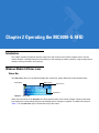
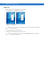

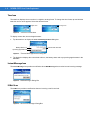
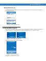
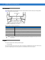
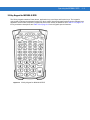

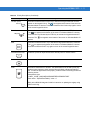


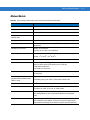
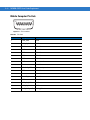


![MC909X User Guide [English] (P/N 72E-72215](http://vs1.manualzilla.com/store/data/006923233_1-b8645820a9c9206bed43f7013f7b5dae-150x150.png)


![MC92N0-G User Guide {English] (P/N 72E-162536-02](http://vs1.manualzilla.com/store/data/005752413_1-5c9790f7378b6b81af8236dfa051ab67-150x150.png)