1
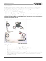
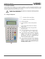
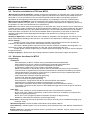
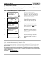
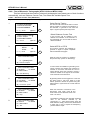
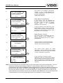
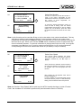
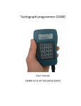
USER’S MANUAL
TACHOGRAPH PROGRAMMER
AND CALIBRATOR
SIEMENS VDO
BTC-BR
BTC-BR
785.001.002/F
BTC-BR User’s Manual
ATTENTION:
¾ Modifications will be reported through Service information (I.S).
¾ This document is property of Siemens VDO Automotive Ltda. All rights reserved.
¾ No part of this material may be copied in any form whatever without the express Siemens VDO
Automotive Ltda. written permission.
¾ This document is for internal use of Siemens VDO Automotive Ltda. and their Authorized
Representatives.
¾ This document could be transferred to third parties only with the express permission in writing and
guaranteed by Siemens VDO Automotive.
Edited by:
Department of Technical Assistance
Responsibility for the content:
Mr. Maurício L. Mullin – Technical Assistance
[email protected]
Responsibility for the issue:
Siemens VDO Automotive Ltda.
Av. Tucunaré, no 491
CEP: 06460-020
Barueri/SP
Tel.: (11) 4166-5000
Fax: (11) 4166-5050
Technical and design modifications are reserved. Printed in Brazil.
NOTE
THIS PUBLICATION WAS EDITED BY DEPARTMENT OF
TECHNICAL ASSISTANCE, DIVISION OF SERVICE & SPECIAL
SOLUTIONS.
The informations and instructions contained in this publication
are only for use of the Network Authorized Service. It does not
replace or restore any technical information contained in
specific documents of our Engineering or other official
publication of Siemens VDO Automotive.
2
BTC-BR User’s Manual
Contents:
1 – General Description of Product ............................................................... 4
1.1 – Accessories ..................................................................................................... 5
1.2 – Applications ..................................................................................................... 5
2 – Functions Available ....................................................................................... 6
2.1 – Using the Keyboard ................................................................................ 6
2.2 – Functions available for KTCO and MTCO .............................................. 7
2.3 – Exclusive functions for MTCO ................................................................ 7
2.4 – Description of Functions ......................................................................... 8
2.4.1 – Automatic Measurement of the “W” factor for MTCO .................................. 8
2.4.2 - Automatic Measurement of the “W” factor for KTCO.................................... 8
2.4.3 –Manual Measurement of “W” factor for MTCO ............................................. 9
2.4.4 - Manual Measurement of “W” factor for KTCO.............................................. 9
2.4.5 – Bank Mobile ................................................................................................. 10
2.4.6 – Constant Measurement of “K” for MTCO..................................................... 10
2.4.7 - Constant Measurement of “K” for KTCO ...................................................... 10
2.4.8 – Test of Electronic Tachographs ................................................................... 11
2.4.8.1 – Distance Counter Test (Odometer)................................................................... 11
2.4.8.2 –Test Chart (Proof of Operation).......................................................................... 12
2.4.8.3 – Variable-Speed Test ......................................................................................... 14
2.4.9 – Programming ............................................................................................... 15
2.4.9.1 – Installation ......................................................................................................... 15
2.4.9.2 – Date - Time........................................................................................................ 19
2.4.9.3 – Setup Kitas ........................................................................................................ 20
2.4.9.4 – Manufacturing Data........................................................................................... 20
2.4.9.5 – Erase Memory Errors ........................................................................................ 21
2.4.9.6 – Software Version............................................................................................... 21
2.4.10 – Change of Language ................................................................................. 21
3 – Technical Details ..................................................................................................... 22
3
BTC-BR User’s Manual
1 – General Description of Product
The new Tachograph Programmer and Calibrator Siemens VDO Automotive main goal is to offer one
more tool in tests and measurements of current tachographs, specifically for KTCO 1308, KTCO
1310, KTCO 1318 and MTCO 1390 models.
With the new equipment is possible to measure, generate test chart, simulate speed and, in cases of
MTCO 1390, even to program the equipment. Its main feature is to bring together in one unit, two
other essential to care of modern tachographs with which you will encounter in your daily life.
Besides practical to operate, it is also easy to be handled and can apply it both on the bench as the
vehicle itself in test, thus eliminating the need to remove the tachograph for tests.
It replaces with advantages the current calibrators in use, including the HTC 1602.19.
The equipment can be powered using the battery of the vehicle or an external source that is within the
standards specified voltage.
The connection with the tachograph is direct, by a single cable and without the need of any additional
component. A standard RS232 serial port is available for general purposes, such as communicating
with a bar-code reader, a printer or a microcomputer.
One of the innovations in this new equipment is the possibility of making automatic measurements,
i.e. without the need of the operator to define the beginning and end of the measurement.
One of the options is using it attached to an optical sensor and it will be responsible for determinating
the beginning and the end of the measurement of twenty meters automatically.
Also new in this equipment relates to the fact that it can be attached to the Portable Roll Test
(1602.26.160.267F) and thus simulate tracks calibration with 20, 50, 100 and 1000 meters. With this
additional facility your measurements will gain speed, accuracy and quality.
1
2
3
1. RJ – 6 Connector (exit RS 232)
2. Self-Lock Connector (tachographs)
3. Mini DIN 6 Connector (Portable Roll
Test / Optical Sensor )
Fig. 01: External Connections (basic lower)
4
BTC-BR User’s Manual
1.1 - Accessories
The Tachograph Programmer and Calibrator Siemens VDO Automotive comes in carrying pouch
(handbag) with two compartments, one for packing the tachograph programmer and manual of
operation and other for packing the cables and optical sensors (optional).
The cables consist of 06 parts, as follow:
1. Cables for testing the KTCO 1318 / KTCO 1310
2. Cables for testing and programming the MTCO 1390
3. Cables with claws type alligator for feeding through external source to the vehicle or any other point
than that of cigarette lighter.
4. Cables for feeding through the cigarette lighter of the vehicle.
5. Adapter box for benchmarking of mechanical tachograph (use with sensor of 08 or 10 impulses/lap)
6. Adapter box for Portable Roll Test.
Note: cables 4 and 5 must be connected to the cables 1 or 2, as needed.
1
5e6
4
2
3
Fig. 02: Cables (accessories)
1.2 – Applications
•
•
•
•
•
•
•
Measurement of electronic tachograph MTCO 1390
Measurement of electronic tachograph KTCO 1318 / KTCO 1310
Measurement of mechanical tachograph KTCO 1308
Test Chart
Variable speed test and odometer
Programming date/time on electronic tachograph MTCO 1390 with an error of more than 24hs
Programming the number of chassis, constant “K”, odometer, among others, for electronic
tachograph MTCO 1390
5
BTC-BR User’s Manual
2 – Functions Available
In this chapter will be detailed all the functions available in portable tachograph programmer, some
common to both lines of tachograph, KTCO e MTCO. All functions are accessed through the alphanumerical keyboard and then will be seen as using it.
All data entry is highlighted with underscore characters indicating that the
“edition” mode will be active.
2.1 – Using the Keyboard
5 6 ⇒ direction of the cursor (Menu)
3 4 ⇒ direction of the cursor (Edition)
E ⇒ confirms operation
C ⇒ cancel operation or return to the previous
menu
L ⇒ clean a field of data, letters and numbers
(edition mode)
F1 ⇒ use only in some cases, being specified
when this occurs
F2 ⇒ return the keyboard to the numerical mode,
i.e., numbers 0-9, “.” and “+/-“ ( edition mode)
F3 ⇒ use characters from A to M of the keyboard,
located at the top left of the numerical
keyboard. The yellow led, corresponding to
this selection, will be lit, showing that this
function is enabled (edition mode)
F4 ⇒ use characters from N to Z of the keyboard,
located at the top right of the numerical
keyboard. The green led, corresponding to this
selection, will be lit, showing that this function
is enabled (edition mode)
6
BTC-BR User’s Manual
2.2 – Functions available for KTCO and MTCO
Measurement of the W Automatic: it allows measure the tachograph in an automatic way, using as start and
end of measurement a system with optical barrier (optional) and two points of reference 20 meters away from
each other. It is more accurate than the conventional method because it does not require the operator’s
participation at the beginning and end steps of the operation by increasing the accuracy of measurement.
Measurement of the W Manual: it allows measure the tachograph using two points of reference to a predeterminated distance from each other. It is necessary the operator’s intervention for the beginning and end of
the operation. It is the conventional method of measurement.
Roller Set: it also allows measure the tachograph in an automatic way, using as start and end of measurement
a pulses counting system emitted by the wheel of measurement of distance. It is more accurate than the optical
barrier method because they may have greater distances (50, 100 and 1000 meters) and the loss of pulses in
these cases does not influence as much as the standard distance (20 meters). It also does not require the
operator’s participation at the beginning and end steps of the operation by increasing the accuracy of
measurement.
Reading of Adjusted K: it reads the value of the constant “K” adjusted in the tachograph. For KTCO you can
adjust it and make a rereading of the new value. For the MTCO the adjustment is made by programming.
Device Testing:
Distance Counter Test: it allows measure the indication of the odometer and to know whether the
indication of the distance travelled is the actual distance that the vehicle went.
Test Chart: it allows generate a test chart and to note the conditions of operation of tachographs. It is
executed in 22 steps, has estimated duration of 1h50’ and can be interrupted at any time.
Variable Speed: it allows programming a constant speed and changing it at any time unless unprogram
the previous speed.
Change Language: it allows switch the language operation between Portuguese, English and Spanish.
2.3 – Exclusive functions for MTCO
Programming:
Installation:
Read parameters of MTCO: it allows storing all the parameters described below
Write parameters in MTCO: it allows recording all the parameters described below
K Adjustment: programming of the constant of adjustment of the MTCO
N Adjustment: programming of the constant of the RPM (optional)
Wheel Circumference: it records the dynamic radius of the wheel with the tire (only information)
Total Odometer: it programmes the total value of the distance in kilometers travelled by the vehicle
Vehicle Identification: it records the vehicle number of chassis where it will be installed the MTCO
Configuration: Keep the original programming
CAN Configuration: Keep the original programming
Product Code: Keep the original programming
Drive Axis: Keep the original programming
Initial Installation: it programmes the date on which the MTCO was installed
Calibrate Date: it programmes the dates of measurement of constant “K”
Seal Number: Record the name/number of representative that mesure/seal the MTCO
Over Speed: it programmes the removal of alarm (D4) and trigger device noise or light for maximun
speed reached
Date-Time:
MTCO Time: it allows to correct the date and time that it is programmed in the MTCO
MTCO Time Zone: it allows programming a value of time zone to be considered on European time.
Keep the original programming.
MTCO Over Time: It programme dates of automatic exchange of daylight saving.
Disable for national MTCOs. Keep the original programming.
Setup Kitas: it allows programming the operation of the sensor according to the installed tachograph (only
for MTCO 1390).
Manufacturing Data: it shows the date of manufacture of the board of MTCO.
Erase Memory: it deletes system errors in the memory of the extended menu. See “Manual of Operation of
MTCO”.
Software Version: it indicates the software version’s operating in the calibrator. Only for control of lot of the
manufacturer of the equipment.
7
BTC-BR User’s Manual
2.4 – Description of functions
Then each function will be detailed in sequential order, for the two lines of tachograph, because the
operations are the same. The content of the display, for each case, will also be presented along the
sequence that must be carried out by the keypad.
2.4.1 – Automatic Measurement of “W” factor for MTCO
Steps
1
Contents of the display
E
AUTO MEASURING
MTCO
←
KTCO
(5/6) - Scroll
3
(E) Enter
(E) Enter
E
AUTO. MEAS. - MTCO
PULSES: [0000]
WAITING START ...
AUTO MEAS - MTCO
PULSES: [0015]
WAITING END...
By going to the first sensor, will start up
automatically the counting of pulses,
ending up only with the passage through
the second sensor.
AUTO MEAS - MTCO
W MEAS: [17586] P/Km
(C) Exit
This function prepares the Calibrator to
capture the speed signal from the
sensor, including differentiating it in
amplitude and format.
At this moment drive the vehicle toward
the first optical sensor and continue
toward the second that must be distant
20m from the first one.
(C) Exit
5
This function is the automatic measurement
of W factor, using two optical sensors
(optional). In this case they must be
positioned at 20 meters of each other and the
issuer must be fixed to the vehicle.
Select MTCO
(C) Exit
4
Procedures
Select Auto Measurement W.
1. AUTO MEAS W ←
2. MANUAL MEAS W
3. ROLLER SET
(6) – Scroll
2
Keys
C
After the passage through the second
sensor
the
counting
ends
up
automatically and the value to be
adjusted to the constant “K” is shown on
display.
2.4.2 - Automatic Measurement of “W” factor for KTCO
For the measurement of automatic “W” factor in a vehicle equipped with KTCO, just run the same
previous procedure from the step 1, by changing the cable for tests and the option in step 2 from
MTCO to KTCO.
For the measurement of the mechanical tachograph KTCO 1308 is necessary to attach the Adapter
Box (page 05/item 05) and use the sensor of 08 or 10 impulses/lap in the gearbox. In this case, the
number of laps/km will be equal to the number of measured pulses divided by the number of emitted
pulses by the sensor, i.e.:
Nº. laps/km = __Nº. measured pulses__
08 or 10 pulses/lap
8
BTC-BR User’s Manual
2.4.3 - Manual Measurement of “W” factor for MTCO
Steps
1
Contents of the display
1. AUTO MEAS W
2. MANUAL MEAS W.
3. ROLLER SET
(5/6) – Scroll
2
4
E
(E) Enter
(C) Exit
(C) Exit
This function is the manual measurement of
W factor, using two points of reference
distant, at least, 20 meters between them. It
is essential the operator’s in this method of
measurement.
Select MTCO
E
F1
This function prepares the Calibrator to
capture the speed signal from the
sensor, including differentiating it in
amplitude and format.
At this moment drive the vehicle toward
the first point of reference and, passing
through it, press the F1 key to start the
measurement.
By reaching the second point of
reference, the operator must press the F2
key to finish the counting of pulses.
F2
Enter the distance traveled between the
two points of reference.
In case of 20 meters, type 2 0 0 0, without
adding point or comma. The calibrator will
understand that this is 20 and not 2000
meters.
MANUAL MEAS - MTCO
LENGTH: [00.00] m
(E) – CALC. W
6
(E) Enter
MANUAL MEAS - MTCO
PULSES: [0015]
(F2) - END
5
←
MANUAL MEAS - MTCO
PULSES: [0000]
(F1) - START
Procedures
Select Manual Meas. W .
MANUAL MEASURING
MTCO
←
KTCO
(5/6) - Scroll
3
Keys
(C) Exit
MANUAL MEAS - MTCO
W MEAS: [17586] P/Km
C
(C) Exit
After entering the value of the distance
traveled and pressing the E key, the value
of the constant “K” being adjusted is
shown on the display.
2.4.4 - Manual Measurement of “W” factor for KTCO
For the measurement of automatic “W” factor in a vehicle equipped with KTCO, just run the same
previous procedure from the step 1, by changing the cable for tests and the option in step 2 from
MTCO to KTCO.
For the measurement of the mechanical macrograph KTCO 1308 is necessary to attach the Adapter
Box (page 05/item 05) and use the sensor of 08 or 10 impulses/lap in the gearbox. In this case, the
number of laps/km will be equal to the number of measured pulses divided by the number of emitted
pulses by the sensor, i.e.:
Nº. laps/km = __Nº. measured pulses__
08 or 10 pulses/lap
9
BTC-BR User’s Manual
2.4.5 – Roller Set for KTCO and MTCO
Steps
1
Contents of the display
(E) Enter
ROLLER
SET
MTCO
KTCO
(5/6) - Scroll
E
This function prepares the equipment for
taking measurements of the “W” factor using
the Portable Roll Test (1602.26.160.267F).
From this screen the instructions must be
followed from the manual of operation of the
Portable Roll Test.
←
(E) Enter
Procedures
Select Roller Set
1. AUTO MEAS W
2. MANUAL MEAS W
3. ROLLER SET
←
(5/6) – Scroll
2
Keys
E
Note: To use other banks of test is necessary to calculate the “W” of equipment through the formula:
[(2 x π x r) x 8] x 1000
where: π (pi) = 3,1416
r = radius of the roll of traction
2.4.6 - Measurement of the Constant “K” for MTCO
Steps
1
Contents of the display
This function reads the value of the constant
“K” pre-adjusted in the tachograph.
E
Select MTCO
CHECK K MEASURING
MTCO
←
KTCO
(5/6) - Scroll
3
(E) Exec.
(E) Enter
This function prepares the Calibrator to
inject a signal of speed and measure its
return, by calculating the value of “K”.
E
CHECK K MEASURING
K = 08000 P/Km
(C) Exit
Procedures
Select Check K Measuring
2. MANUAL MEAS W
3. ROLLER SET
4. CHECK K MEASUR ←
(5/6) – Sel.
2
Keys
C
The value presented is the preprogrammed into the tachograph. In
case of MTCO, the value of “K” can
only
be
adjusted
by
the
“PROGRAMMING”.
2.4.7 – Measurement and adjustment of the constant “K” for KTCO
For the measurement of the constant “K” in a vehicle equipped with KTCO, just run the same previous
procedure from step 1, changing up the option in step 2 from MTCO to KTCO. In this case the readed
value can be adjusted through the programming keys and must be checked by repeating the previous
procedure.
ATTENTION: This function is not applicable to the mechanical tacrograph KTCO
1308.
10
BTC-BR User’s Manual
2.4.8 – Test of Electronic Tachographs (KTCO 1318 and MTCO 1390)
This item allows that the models of electronic tachographs have tested some of their functions
automatically, such as: Distance Counter Test, Test Chart and Variable Speed Test.
2.4.8.1 – Distance Counter Test (Odometer)
Steps
1
Contents of the display
(E) Enter
(E) Enter
This function will access a sub-menu in which
will be possible to measure the indication of
the odometer, to generate a test chart and
inject a signal of speed previously known.
Select Distance Counter Test
E
DIST COUNTER TEST
MTCO
←
KTCO
(5/6) - Scroll
4
E
1. DIST COUNT TEST←
2. TEST CHART
3. VARIABLE SPEED
(6) – Scroll
3
(E) Enter
Procedures
Select Device Testing
4. CHECK K MEASUR.
5. DEVICE TESTING ←
6. PROGRAMMING
(5/6) – Scroll
2
Keys
In this function will be possible to test
whether the indication of the odometer of
the tachograph is in accord with the actual
distance traveled.
Select MTCO or KTCO
E
DIST COUNTER TEST
This function prepares the Calibrator to
generate a signal of speed compatible
with the selected tachograph.
Enter the value of constant “K” readed in
the previous step. (Check “K” Measuring).
K = [08000] P/Km
(E) – Reference Adjust
5
DIST COUNTER TEST
S= 20 Km/h
K= 08000
D= 0000 meters
(E) – Start Measuring
6
E
DIST COUNTER TEST
S= 20 Km/h
K= 08000
D= 0987 meters
(E) – Stop
8
E
DIST COUNTER TEST
S= 100 Km/h
K= 08000
D= 0095 meters
(E) – Decrement Speed
7
E
E
DIST COUNTER TEST
S= 0 Km/h
K= 08000
D= 1002 meters
(C) – Exit
C
In this moment the calibrator is generating a low
signal of speed and awaiting the command to
increase to 100 Km/h and starts the count in
meters. Before giving the command, choose a
reference number on the right of the numerator
of the odometer and memorize it.
By pressing E the counter triggers the count and
the speed goes to 100 km/h. When it is 950
meters, press E to reduce the speed. Doing this
will be easier to synchronize the counter with the
odometer.
When the numerator of reference, in the
tachograph, arise again, press E and
check if the counter closed the count near
1000 ± 20 metros.
The distance traveled by the odometer should be
close to the distance indicated by the
programmer, i.e., 1000 meters. Being within the
limits tolerated, simply close the test, otherwise do
it again and in case of repeat the discrepancy,
proceed with the repair.
11
BTC-BR User’s Manual
2.4.8.2 – Test Chart (Proof of operation)
Steps
1
Contents of the display
(E) Enter
TEST CHART
MTCO
KTCO
(5/6) - Scroll
4
E
E
E
(E) – Start
Enter the value of constant “K” readed in
the previous step. (Check “K” Measuring).
(C) Exit
E
Enter the value corresponding to the larger
scale of the speed in the display of
speedometer/tachograph. The most usual is
125 km/h. See Table 01.
TEST CHART
MEAS RANGE =[125] Km/h
(5/6) - Scroll
6
(E) Cont.
E
TEST CHART
S= 000
t= 075
P= 01
MR=125km/h
K=08000
The automatic test starts in the step 01. They are
22 steps with duration and speed variables (see
Table 01). The total time of the test is 1h50’, and
may be interrupted at any time.
(C) – Exit
7
This function prepares the Calibrator to
generate a signal of speed compatible
with the selected tachograph.
TEST CHART
K = [08000] P/Km
5
In this function will be possible to generate
a disk of proof of good operation of
tachograph or if there is an anomaly in the
recording.
Select MTCO or KTCO
←
(E) Enter
This function will access a sub-menu in which
will be possible to measure the indication of
the odometer, to generate a test chart and
inject a signal of speed previously known.
Select Test Chart
1. TESTE DE DIST.
2. TEST CHART
←
3. VARIABLE SPEED
(5/6) – Scroll
3
(E) Enter
Procedures
Select Device Testing
4. CHECK K MEASUR
5. DEVICE TESTING ←
6. PROGRAMMING
(5/6) – Scroll
2
Keys
TEST CHART
S= 000
t= 001
P= 22
∗ ∗ ∗ END OF TEST ∗ ∗ ∗
(C) – Exit
C
At the end of the test will be issued
information on the screen of the
programmer and the red led will be lit until
pressed the C button.
12
BTC-BR User’s Manual
Table 01:
60
Step
P1
P2
P3
P4
P5
P6
P7
P8
P9
P10
P11
P12
P13
P14
P15
P16
P17
P18
P19
P20
P21
P22
Duration
(seconds)
75
300
600
75
75
75
10
75
75
75
600
10
600
10
600
10
600
10
600
600
600
600
80
90
Scale range
100 105 120
125(*)
140
130
135
150
40
80
120
130
120
80
40
40
80
120
135
120
80
40
40
80
120
150
120
80
40
40
40
40
80
80
80
120
120
120
130
120
80
40
135
120
80
40
150
120
80
40
Speed (Km/h)
70
90
100
110
20
50
70
70
70
50
20
30
60
90
90
90
60
30
30
60
90
100
90
60
30
30
60
90
110
90
60
30
20
30
30
30
50
60
60
60
70
90
90
90
70
70
50
20
90
90
60
30
100
90
60
30
110
90
60
30
0
115
0
30
60
90
115
90
60
30
0
30
0
60
0
90
0
115
90
60
30
0
(*) Value of scale ranges more common for tachograph Siemens VDO Automotive.
13
BTC-BR User’s Manual
2.4.8.3 – Variable Speed Test
Steps
1
Contents of the display
(E) Enter
(E) Enter
This function will access a sub-menu in which
will be possible to measure the indication of
the odometer, to generate a test chart and
inject a signal of speed previously known.
Select Variable Speed
E
VARIABLE SPEED
MTCO
←
KTCO
(5/6) - Scroll
4
E
1. DIST COUNT TEST
2. TEST CHART
3. VARIABLE SPEED ←
(5) – Scroll
3
(E) Enter
Procedures
Select Device Testing
4. CHECK K MEASUR
5. DEVICE TESTING ←
6. PROGRAMMING
(5/6) – Scroll
2
Keys
In this function will be possible to generate a
signal of speed and change it gradually from
more to less, observing the behavior of the
indicator (speedometer).
Select MTCO or KTCO
E
VARIABLE SPEED
K = [08000] P/Km
This function prepares the Calibrator to
generate a signal of speed compatible
with the selected tachograph.
Enter the value of the constant “K” readed
in the step 2.4.5 (Check “K” Measuring).
E
(E) – Speed Adjust
5
VARIABLE SPEED
K = [08000] P/Km
S = [100] Km/h
(E) – Start
6
E
VARIABLE SPEED
K = [08000] P/Km
S = [100] Km/h
(E) – Speed Adj
7
(C) Exit
Enter the value of speed that you want the
tachograph indicate, observing the value of the
scale range. Press E to the test operates.
(C) Exit
E
By activated the test, the value of speed can not
be edited more, only by pressing E again. By
pressing the button E it will be possible to adjust
the value of speed. In this moment is released
the editing mode to the desired value.
VARIABLE SPEED
K = [08000] P/Km
S = [060] Km/h
(E) – Start
(C) Exit
C
14
BTC-BR User’s Manual
2.4.9 – Programming
This item is divided into 05 (five) sub-items: Installation, Date-Time, Manufacturing Data,
Erase Memory and Software Version. For each sub-items there are others sub-items that will allow
programming of specific functions of MTCO.
2.4.9.1 – Installation
Steps
1
Contents of the display
4. CHECK K MEASUR
5. DEVICE TESTING
6. PROGRAMMING
←
(5/6) – Scroll
2
(E) Enter
(E) Enter
7
E
C
(E) Enter
W ADJUST * * *
[25054] P/Km
* * *
(E) – Ajustar
(C) Sair
After completion of reading, the data
remain stored in the memory of the
programmer and can be recorded in other
unprogrammed MTCO.
Select Write Parameters
This function is a complement of the
previous. In this case the parameters are
recorded in the MTCO to be installed.
E
After completion of writing, the new MTCO is
able to be installed on the vehicle from which
the defective equipment was removed.
C
1. READ PARAMETERS
2. WRITE PARAMETERS
3. PROGRAMMING K ←
(5/6) – Scroll
8
In this function will be possible to read the
parameters necessary for programming a new
MTCO identical to the defective.
WRITE PARAMETERS
WRITE OK!
(C) Exit
This function will access a sub-menu in which
will be possible to read and record all the
programmable parameters of MTCO, and to
program one by one, if necessary.
Select Read Parameters
1. READ PARAMETERS
2. WRITE PARAMETERS←
3. PROGRAMMING K
(5/6) – Scroll
6
E
READ PARAMETERS
READ OK!
(C) Exit
5
Select Installation
1. READ PARAMETERS←
2. WRITE PARAMETERS
3. PROGRAMMING K
(5/6) – Scroll
4
Select Programming
←
(E) Enter
Procedures
This function will access a sub-menu in which
will be possible to make all necessary
adjustments to the operation of MTCO.
(E) Enter
1. INSTALLATION
2. DATE - TIME
3. MANUFACT DATA
(6) – Scroll
3
Keys
E
This function allows changing the constant of
correction “K” of the tachograph MTCO. This is
one of the parameters that the function “Read or
Save Parameters” keep in memory. This
adjustment is necessary for the MTCO
understand the sign of speed from the sensor as
being the real.
In case of wanting to correct the constant “K”,
press L to clear the fields of editing, enter the
desired value and press E. This adjustment is
similar to the installing a reducer in the
mechanical tachograph or adjustment of the keys
in the electronic tachograph.
15
BTC-BR User’s Manual
Steps
9
Contents of the display
11
(E) Enter
Select Distance Counter
E
This function allows programming the total
distance traveled in the equipments of
exchange and keeping them as the original
vehicle mileage.
In case of wanting to correct the kilometers
traveled, press L to clean the field of editing,
enter the desired value and press E.
(C) Exit
This function allows logging the vehicle
identification where the MTCO will be installed.
This function is an item of security and will help
in cases of traceability of equipment.
←
(E) Enter
E
VEHICLE IDENTIF.
[9BWV2VD23YRY03520]
F1-SUB
(E) – Adjust
In this function must be registered the
perimeter or radius of the wheel, with tire, from
the vehicle where the MTCO is installed.
Auxiliary function in the mathematical
calculation of the constant”K”.
In case of wanting to correct the value of the
perimeter/radius, press L to clean the fields of
editing, enter the desired and press E. This
programme is only informative, does not affect
the operation of the tachograph.
(C) Exit
7. VEHICLE IDENT.
8. CONFIGURATION
9. CAN CONFIG.
(5/6) – Scroll
15
E
DISTANCE COUNTER
[0013586] Km
(E) – Adjust
14
(E) Enter
4. N - ADJUSTMENT
5. WHEEL CIRCUMFER
6. DIST COUNTER
←
(5/6) – Scroll
13
Select Wheel Circumference
WHEEL CIRCUMFER
[5100] mm
(E) – Adjust
12
Select next function.
(E) Enter
4. N - ADJUSTMENT
5. WHEEL CIRCUMFER←
6. DIST COUNTER
(5/6) – Scroll
Procedures
This function is not enabling to tachograph
currently in use. It allows adjusting the
constant of adaptation to indication/recording
of engine speeds (RPM).
4. N - ADJUSTMENT ←
5. WHEEL CIRCUMFER
6. DIST COUNTER
(5/6) – Scroll
10
Keys
(C) Exit
E
In case of wanting to correct the vehicle
identification, press L to clean the field of editing,
enter the desired value and press E. In case of
wanting to replace only one character, press F1,
select the desired character and enter the new
value for it.
Note: In this function can be used the F1 key to help in the edition of the vehicle identification. This key
alternate the editing mode between overwrite or insert character. While on the screen of the
programmer the description F1-SUB the editing mode will allow to insert new characters erasing the
first from left to right. When it is in the function F1-INS, will be available the mode of replacement
only from the selected character. To enter the characters in yellow press F3 (from A to M), for the
green characters press F4 (from N to Z), and for numbers press F2 (from 0 to 9). At this moment the
corresponding led to the mode selected will remain on (for letters) or off (for numbers).
16
BTC-BR User’s Manual
Steps
16
Contents of the display
7. VEHICLE IDENT.
8. CONFIGURATION
9. CAN CONFIG.←
(5/6) – Scroll
17
19
(E) Enter
Select next function.
(E) Enter
Select Drive Shaft
E
(C) Exit
E
(E) Enter
(C) Exit
(E) Enter
(C) Exit
In case of wanting to correct the relation of
reduction, press L to clean the field of editing,
enter the desired value and press E. This
programme is only informative, does not
affect the operation of the tachograph.
E
Function of control. It records the date on which
the MTCO was installed. This function is
optional, however important in tracking the
product.
E
To register the Initial Installation, must be
pressed E to change the field, i.e., enter the day
and press E, enter the month and press E, and
finally enter the year and press E. At the end
press F1 and the date will be effective.
Select Calibrate Date
E
CALIBRATE DATE
[05 / 01 / 01]
F1 – Adjust
This function records the relation of reduction
of the rear axle of the vehicle. Auxiliary
function in the mathematical calculation of the
constant”K”.
Select Initial Installation
12. INITIAL INSTAL.
13. CALIBRATE DATE ←
14. SEAL NUMBER
(5/6) – Scroll
23
This function is not enabling to tachograph
currently in use. Modify since the configuration
of the display until the exhibition modes and
must
not
be
changed
under
any
circumstances.
INITIAL INSTALLATION
[05 / 01 / 01]
F1 – Adjust
22
Select next function.
10. PRODUCT CODE
11. DRIVE SHAFT
12. INITIAL INSTAL.
←
(5/6) – Scroll
21
(E) Enter
DRIVE SHAFT
[00,01] I/U
(E) – Adjust
20
←
10. PRODUCT CODE
11. DRIVE SHAFT
←
12. INITIAL INSTAL.
(5/6) – Scroll
Procedures
These functions are not enabling to
tachograph
currently in use. They are
included in the configuration of the product
and must not be changed in any hypothesis.
10. PRODUCT CODE ←
11. DRIVE SHAFT
12. INITIAL INSTAL.
(5/6) – Scroll
18
Keys
E
Function of control. It records the date on which
the measurement of MTCO was made. It is an
optional function, however important in the
tracking of the measurements by which the
MTCO passed.
To register the Calibrate Date, must be pressed
E to change the field, i.e., enter the day and
press E, enter the month and press E, and finally
enter the year and press E. At the end press F1
and the date will be effective.
17
BTC-BR User’s Manual
Steps
24
Contents of the display
(E) Enter
E
Function of control. It records the number or
name of the person responsible for last
measurement of MTCO. Important function in
the control of those responsible for
measurements made.
To record the desired information, press L to
clean the field of editing, enter the desired
name/number and press E. In case of wanting
replace only one character, press F1, select
the desired character and enter the new value
for it.
SEAL NUMBER
[SIEMENS VDO]
F1-SUB
(E) – Adjust
Procedures
Select Seal Number
12. INITIAL INSTAL.
13. CALIBRATE DATE
14. SEAL NUMBER
←
(5/6) – Scroll
25
Keys
(C) Exit
Note: In this function can be used the F1 key to help in the edition of the vehicle identification. This key
alternate the editing mode between overwrite or insert character. While on the screen of the
programmer the description F1-SUB the editing mode will allow to insert new characters erasing the
first from left to right. When is the function F1-INS, will be available the mode of replacement only
from the selected character. To enter the characters in yellow press F3 (from A to M), for the green
characters press F4 (from N to Z), and for numbers press F2 (from 0 to 9). At this moment the
corresponding led to the mode selected will remain on (for letters) or off (for numbers).
Steps
26
Contents of the display
13. CALIBRATE DATE
14. SEAL NUMBER
15. OVER SPEED
(5) – Scroll
27
Keys
Select Over Speed
←
(E) Enter
OVER SPEED
[- - - -] km/h
READING MTCO
(E) – Adjust
28
E
This function allows adjusting the speed
from which a light or sound device could be
triggered, activated by the D4 output of
MTCO.
At this moment the calibrator will check what is
the value pre-adjusted to the MTCO. This will
be possible only if the tachograph have that
function.
(C) Exit
OVER SPEED
[080] Km/h
(E) – Adjust
Procedures
(C) Exit
After reading the pre-adjusted value will be
possible reprogram it.
In case of wanting to correct the trigger point of
the external device, press L to clean the field of
editing, enter the desired value and press E.
Note: the function “Over Speed” will be valid only for MTCO models that have, in their “Product
Code”, the numbers 007 and 008 in position hhh (see Information Service T033/02).
18
BTC-BR User’s Manual
2.4.9.2 – Date - Time
Steps
1
Contents of the display
1. INSTALLATION
2. DATE - TIME ←
3. MANUFACT DATA
(5/6) – Scroll
2
(E) Enter
(E) Enter
E
(C) Exit
This function will access a sub-menu in which
will be possible to adjust date/time, time zone
and over time.
Select MTCO Time
E
This function will allow correcting the current
date (day, month and year) and hour/minutes.
This function is necessary only if the MTCO
present an error greater than 01 day (or 24
hs).
To change the values of interest, press E for
change of field to each value entered and, at
the end, press F1 and the modification will be
effective.
SYSTEM TIME UTC
DATE:
05 / 01 / 2001
TIME:
10:38:25
F1 – Adjust
Procedures
Select Date - Time
1. MTCO TIME ←
2. MTCO TIME ZONE
3. MTCO OVER TIME
(6) – Scroll
3
Keys
E
Note: in this function should be adjust the value of hours always with 01 (one) hour more than the
desired. This is necessary because the Tachograph Programmer / Calibrator leaves the factory
with a pre-adjusted time zone in less one hour (–01:00hs) than the desired time to adjust. This
difference is compensated at the time of adjustment of hours. For instance: in case of wanting
to adjust the hours to 12:10 pm, you must enter 13:10hs and the calibrator itself will correct the
difference.
ATTENTION: Every time when there is change of hours in MTCO, you must open the
disk compartment and correct the time of recording in the disk diagram.
See “Manual of Operation of MTCO”.
4
(5/6) – Scroll
5
(E) Enter
E
TIME ZONE
-01:00 h
F1 – Adjust
6
Select Time Zone
1. MTCO TIME
2. MTCO TIME ZONE ←
3. MTCO OVER TIME
(C) Exit
E
1. MTCO TIME
2. MTCO TIME ZONE
3. MTCO OVER TIME ←
(5) – Scroll
(E) Enter
C
This function adjusts the value of the time
zone to be compared with the world
standard time (UTC). It is pre-adjusted in
less one hour (-01:00).
If you do not want to run the process of the
previous observation, simply reset the time
zone. For this, enter the value zero twice,
press E, and then F1. We recommend not
changing the original settings of Tachograph
Programmer / Calibrator.
This function is
currently in use.
which the MTCO
time and must
circumstances.
not enabling to tachograph
Program dates and times in
changes automatically to over
not be changed under any
Select next function.
19
BTC-BR User’s Manual
2.4.9.3 – Activate Kitas
Steps
1
Contents of the display
←
(E) Enter
E
(C) Exit
E
SETUP KITAS
SETTING...
(E) Setup
4
This function allows that the sensor Kitas,
installed on the vehicle, is recognized by
tachograph MTCO 1390. This transaction affects
the operation of the tachograph and should be
used whenever there is exchange of the sensor
or the tachograph MTCO 1390.
SETUP KITAS
(E) Setup
3
Procedures
Setup sensor model Kitas (*)
1. INSTALLATION
2. DATE - TIME
3. SETUP KITAS
(5/6) – Scroll
2
Keys
(C) Exit
E
SETUP KITAS
SENSOR ACTIVATED
(E) Setup
(C) Exit
(*) the sensor Kitas is a differential model. It has
the normal functions of the sensor Hall (positive,
negative and signal of speed) and also a
communication with the MTCO 1390.
If the sensor is not “enabled” it will not recognize
the tachograph and vice versa.
As a result the MTCO will record the speed
normally, when in motion, and will acknowledge
the failure of the sensor when stopped. This can
be seen through the continuous recording from 0
to 30 km/h on the scale of speed of the disk
diagram.
The sensor Kitas is identificated by code
2170/2171 printed in its body. The other numbers
identify the features of each sensor Kitas, for
example, the length of the rod.
C
2.4.9.4 – Manufacturing data
Steps
1
Contents of the display
2. DATE - TIME
3. SETUP KITAS
4. MANUFACT DATA
(5/6) – Scroll
2
Keys
Procedures
Select Manufacturing Data
←
(E) Enter
E
This function informs the date on which the
MTCO’s board was manufactured. This
programme is only informative, does not affect
the operation of the tachograph and can not be
changed.
MANUFACTURING DATA
DATE:
31 / 08 / 99
(C) Exit
C
20
BTC-BR User’s Manual
2.4.9.5 – Erase memory
Steps
1
Contents of the display
1. MANUFACT DATA
2. ERASE ERROR MEM←
3. SW VERSION
(5/6) – Scroll
2
Keys
(E) Enter
Procedures
Select Erase Memory
E
This function allows erase all the errors of
system recorded in the memory of MTCO.
See “Manual of Operation of MTCO”.
ERASE ERROR MEMORY
ERASING OK!
(E) Erase
(C) Exit
E
2.4.9.6 –Software Version’s
Step
1
Contents of the display
(E) Enter
Procedures
Select Software Version’s
1. MANUFACT DATA
2. ERASE ERROR MEM
3. SW VERSION
←
(5) – Scroll
2
Keys
E
This function informs the software version’s in
use in the Tachograph Programmer /
Calibrator. This programme is only informative,
does not affect the operation of the tachograph
and can not be changed.
SOFTWARE VERSION
BTC – BR V 1.2
(C) Exit
C
2.4.10 – Change of Language
This item allows all screens of operation of the calibrator will be shown in the chosen
language. The standard option is Portuguese, but could be replaced by Spanish or English.
Step
1
Contents of the display
5. DEVICE TESTING
6. PROGRAMMING
7.CHANGE LANGUAGE ←
(5) – Scroll
2
Keys
(E) Enter
Procedures
Select Change Language
This function will show the current language
of the operation of calibrator.
E
By selecting, the text changes between
Portuguese, English, and Spanish.
The <E> key assumes the chosen language.
CHANGE LANGUAGE
PORTUGUESE
(5/6) – Scroll
(E) Enter
E
21
BTC-BR User’s Manual
3 – Technical Details:
Display: .............................................................. LCD (Liquid Crystal Display) illuminated
4 rows x 20 characteres / row
Character of 5 mm high
Keyboard: .......................................................... Keyboard alpha numeric / special characters
System:.............................................................. 80C320 Processor (8051 Family)
64 KB of EPROM
32 KB of RAM
Without buffer
Interfaces: ......................................................... Serial RS 232, RJ6 connector
Supply Voltage: ................................................ 9,0 V – 30,0 V / direct current
(protection against reversal of polarity)
Rated Voltage: .................................................. 12,0 Vdc
Power Consumption:........................................ 170 mA (12 V)
Operating Temperature:................................... 0°C to + 40°C
Size:.................................................................... 236 x 125 x 41 mm
(C x L x A)
Cables:............................................................... 1,0 m (length)
Weight:............................................................... 0,495 kg
Accessories: .................................................... See chapter 1.1
Material: ............................................................ Box in ABS
22