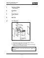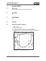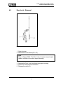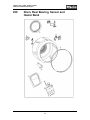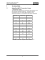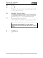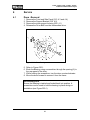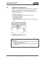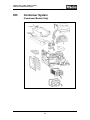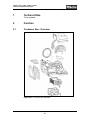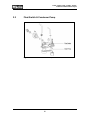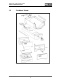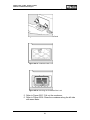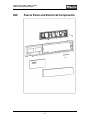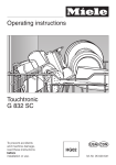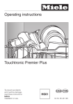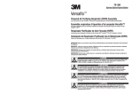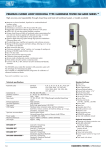
1
TECHNICAL INFORMATION
Touchtronic Clothes Dryers
Includes: T1302, T1303, T1322, T1329ci
T1403 & T1405
© 2004 Miele
This page intentionally left blank.
Table of Contents
GENERAL INFORMATION
A. Warning and Safety Instructions
3
B. Modification History
5
C. Technical Data
7
D. Layout of Electrical Components
9
Vented Models
9
Condenser Models
11
010 – Cabinet and Front Panel
1
Technical Data
13
2
Function
15
3
Fault Repair
15
4
Service
15
4.1 Lid – Removal
15
4.2 Plinth (Toekick) – Removal
16
4.3 Front Panel – Removal
16
4.4 Side Panel – Removal
16
4.5 Support Bracket – Removal
17
4.6 Rear Access Panel – Removal
17
020 – Door and Door Lock
1
Technical Data
19
1.1 Door Lock
21
2
Function
21
3
Fault Repair
21
4
Service
21
4.1 Outer Door Panel – Removal
21
4.2 Door Lock – Removal
22
030 – Drum, Rear Bearing, Sensor and Heater Bank
1
2
Technical Data
23
1.1 Heater Bank (NTC) Temperature Sensor – Resistance Values
25
Function
26
2.1 Residual Moisture Sensor System
26
2.1.1 Residual Moisture Sensing – Drum Assembly
26
2.1.2 Residual Moisture Sensor – Brush Assembly
26
2.2 Drum Bearing
26
2.3 Heating
27
2.3.1 Heater Bank
27
2.3.2 Heater Bank Temperature Sensor
27
2.3.3 Thermostats (Temperature Limiters)
27
3
Fault Repair
27
4
Service
28
4.1 Drum – Removal
28
4.2 Drum Rib – Removal
29
4.3 Slip Ring – Removal
29
4.4 Drum Bearing – Removal
30
4.5 Heater Bank – Removal
31
4.6 NTC Temperature Sensor – Removal
33
4.7 Thermostats (Temperature Limiters) – Removal
34
4.8 Brush Unit (Residual Moisture Sensor) – Removal
34
4.9 Residual Moisture Sensor Carbon Brush – Replacement
35
4.10 Rear Seal – Removal
36
040 – Drive and Fan Motor
1
Technical Data
39
2
Function
39
2.1 Main Motor
39
3
Fault Repair
40
4
Service
40
4.1 Drum Drive Belt – Removal
40
4.2 V-Belt – Removal
41
4.3 Intermediate Drive – Removal
41
4.4 Fan Impeller
41
4.5 Drive Motor – Removal
41
050 – Air Circulation and Front Bearing
1
2
3
4
Technical Data
45
1.1 Temperature Sensor (Fan Housing) – Resistance Values
45
Function
46
2.1 Fill Ring
46
2.2 Front Drum Bearing
46
2.3 NTC Temperature Sensor
46
2.4 Front Seal
46
2.5 Porthole Seal
46
Fault Repair
48
3.1 Drying temperature too high
48
Service
49
4.1 Fill Ring – Removal
49
4.2 Front Drum Bearing - Adjustment
50
4.3 Light Bulb – Replacement
51
055 – Condenser System
1
Technical Data
55
2
Function
55
2.1 Condenser Box – Overview
55
2.2 Float Switch & Condenser Pump
56
2.3 Condenser Drawer
57
Fault Repair
58
3.1 Long Drying Time
58
3.2 Water Leaking from appliance
58
Service
58
4.1 Condenser Box – Cleaning
58
3
4
060 – Fascia Panel and Electrical Components
1
Technical Data
62
2
Function
62
2.1 Heater Relays
62
Fault Repair
63
3.1 Fault Summary
63
Service
64
4.1 Programming Mode
64
4.2 Demonstration Mode (Dealer Displays)
66
4.3 Service Mode
67
4.4 Fascia Panel – Removal
72
4.5 Electronic / Controls – Service Position
73
3
4
Touchtronic Clothes Dryers - List of Figures
D-1 Layout of Components – Vented Models
9
D-2 Layout of Components – Condenser Models
11
010-1 Cabinet Construction
15
010-2 Support bracket
17
020-1 Removing the outer door panel
21
020-2 Door Lock
22
030-1 Drum Bearing
28
030-2 Drum Rib Hardware
29
030-3 Drum Bearing
30
030-4 Heater Bank Components
31
030-5 Wiring Harness Holder
32
030-6 Access Panel to Heater Bank (Removed) with Heater Bank
33
030-7 Wiring Harness Holder
34
030-8 Residual Moisture Sensor Brush Replacement
35
030-9 Rear Drum Seal
36
040-1 Motor and Fan Impellers (Condenser Model)
39
040-2 Drives
40
050-1 Drum Support Housing (vented)
47
050-2 Drum Support Housing (condenser)
48
050-3 Front Drum Support Bearing
50
050-4 Opening the Light Bulb Cover
51
055-1 Condenser Box Assembly
55
055-2 Float Switch and Drain Pump
56
055-3 Condenser Drawer
57
055-4 Condenser Box Access Panel
59
055-5 Condenser Door Lock
59
055-6 Unlocking the Condenser Box Lock
59
055-7 Removing the Condenser Box
60
055-8 Rinsing the side of the Condenser Box
60
055-9 Rinsing the Condenser Box
60
060-1 Fascia Panel Removal
72
060-2 Electronic Retaining Screw
73
060-3 Button Assembly
74
060-4 Electronic / Controls in service position
74
Touchtronic Clothes Dryers - List of Tables
C-1 Overview of Models
7
C-2 Electrical Information
7
030-1 Heater Bank NTC Temperature Sensor Values
25
030-2 Heater Element Activation
26
050-1 Fill Ring NTC Temperature Sensor Values
45
060-1 Fault Summary
63
060-2 Program Mode Positions
65
060-3 Service Mode (1 of 4)
68
060-4 Service Mode (2 of 4
69
060-5 Service Mode (3 of 4)
70
060-6 Service Mode (4 of 4)
71
T1302, T1303, T1322, T1329ci, T1323c,
T1403 and T1405 Clothes Dryers
Technical Information
General Information
1
T1302, T1303, T1322, T1329ci, T1323c,
T1403 and T1405 Clothes Dryers
Technical Information
This page intentionally left blank.
2
T1302, T1303, T1322, T1329ci, T1323c,
T1403 and T1405 Clothes Dryers
Technical Information
A
Warning and Safety Instructions
1
General Information
Service of this appliance should only be performed by qualified
personnel; in accordance with local and national codes.
Power should be disconnected from the appliance during service.
Unplug the appliance, or the shut off the appropriate circuit breaker.
3
T1302, T1303, T1322, T1329ci, T1323c,
T1403 and T1405 Clothes Dryers
Technical Information
This page intentionally left blank.
4
T1302, T1303, T1322, T1329ci, T1323c,
T1403 and T1405 Clothes Dryers
Technical Information
B
Modification History
04/2004
06/2004
08/2004
Miele USA
Miele USA
Miele USA
5
Preliminary Information
Revised
Revised
T1302, T1303, T1322, T1329ci, T1323c,
T1403 and T1405 Clothes Dryers
Technical Information
This page intentionally left blank.
6
T1302, T1303, T1322, T1329ci, T1323c,
T1403 and T1405 Clothes Dryers
Technical Information
C
Technical Data
Overview of Models
Model Number Capacity
5 Kg
T1302
5 Kg
T1303
5 Kg
T1322C
T1329C
5 Kg
T1323C
T1403
5 Kg
6 Kg
T1405
6 Kg
Table C-1: Overview of model
Additional Information
Angled Controls, Vented
Flat Controls, Vented
Angled Controls, Condenser
Fully Integrated Style,
Condenser (match for W1119)
Flat, Condenser
Angled Controls, Vented
Angled Controls, Vented,
Stainless Steel Finish
numbers
Note
All models are left hinged. The door cannot be changed to right
hinge operation.
Electrical Information
Electrical Requirements
Electrical Connection
120/240 (208) VAC
(4 wire connection)
60 Hz, 15amp Circuit
Table C-2: Electrical information
7
NEMA 14-30 Molded Plug
(Do not remove)
T1302, T1303, T1322, T1329ci, T1323c,
T1403 and T1405 Clothes Dryers
Technical Information
This page intentionally left blank.
8
T1302, T1303, T1322, T1329ci, T1323c,
T1403 and T1405 Clothes Dryers
Technical Information
D
Layout of Electrical Components
Vented Models
1. (B3/1)
2. (2R30)
3. (M5)
4. (2K1/1)
5. (1K1/1)
6. (Z1)
7. (1N1)
8. (S2)
9. (H3/6)
10. (F1)
11. (A2)
12. (C5)
13. (1R30)
Residual Moisture Sensor (Drum Ribs, Slip Rings)
NTC Temperature Sensor (Heater Bank)
Main Drive / Fan Motor
Heater Relay
Heater Relay
Interference Suppression Capacitor
Electronic Unit
On/Off Switch
Drum Light
Temperature Limiters-2 (Non Re-settable)
Door Lock
Capacitor – (for Motor M5)
NTC Temperature Sensor (Fan Housing)
Figure D-1: Overview of Components – Vented Models
9
T1302, T1303, T1322, T1329ci, T1323c,
T1403 and T1405 Clothes Dryers
Technical Information
This page intentionally left blank.
10
T1302, T1303, T1322, T1329ci, T1323c,
T1403 and T1405 Clothes Dryers
Technical Information
D
Layout of Electrical Components
Condenser Models
1R30
A2
B3/1
B8/7
C5
1F1 / 2F2
H3/6
K1/1
M5
M13
1N1
R1
R2
1R30
2R30
S2
Z1
Door Lock
Residual Moisture Sensor
Level Switch
Capacitor
Temperature Limiter (Non Re-settable)
Drum Lighting
Heating Relay
Fan And Drum Drive Motor
Condensate Pump (Condenser Dryer Only)
Electronic
Heater Bank
Heater Bank
NTC Temperature Sensor (Fan Housing)
NTC Temperature Sensor (Heater Bank)
On/Off Switch
Interference Suppression Capacitor
Figure D-2: Overview of Components – Condenser Models
11
T1302, T1303, T1322, T1329ci, T1323c,
T1403 and T1405 Clothes Dryers
Technical Information
This page intentionally left blank.
12
T1302, T1303, T1322, T1329ci, T1323c,
T1403 and T1405 Clothes Dryers
Technical Information
010
Cabinet and Front Panel
13
T1302, T1303, T1322, T1329ci, T1323c,
T1403 and T1405 Clothes Dryers
Technical Information
This page intentionally left blank.
14
T1302, T1303, T1322, T1329ci, T1323c,
T1403 and T1405 Clothes Dryers
Technical Information
1
Technical Data
- To Be Updated
2
Function
n/a
3
Fault Repair
n/a
4
Service
4.1
Lid - Removal
Figure 010-1: Cabinet Construction
1. Remove the screw caps from the side edges of the lid.
2. Loosen the screws about 4 to 5 turns.
3. Press in on the screws, lift the lid from the front and slide it
toward the rear. Lift the lid to remove.
Note
It is not necessary to remove the lid to access / replace the
electronic.
15
T1302, T1303, T1322, T1329ci, T1323c,
T1403 and T1405 Clothes Dryers
Technical Information
4.2
Toekick Removal
1. Remove the screw caps, Figure 010-1.
2. Remove the screws.
3. Slide the toekick to the left; pull from the appliance to remove.
4.3
Front Panel - Removal
1.
2.
3.
4.
5.
Open the door.
Remove the two Door Lock screws.
Remove the five screws around the door opening.
Remove the toekick (010 4.2).
Support the panel from the bottom. Remove the two screws
from the bottom corners of the panel.
6. Guide the panel downward to remove it from the appliance.
4.4
Side Panel - Removal
1. Remove the Lid (010 4.1).
2. Remove the Front Panel (010 4.3).
3. Refer to Figure 010-1. Remove the three screws from both rear
edges of the panel.
4. Remove the three screws from the top edge of the panel.
5. Remove the three screws from the front edge of the panel.
6. If equipped - remove the dryer vent (or cap).
7. Pull the panel outward from the top.
8. Push the panel down to unclip it from the bottom of the frame.
Reassembly Note
Install the panel at the bottom first. Ensure the lip on the panel
engages with the frame of the appliance. The 2 middle screws /
washers provide the ground to the panels. Ensure they are tight
during reassembly.
16
T1302, T1303, T1322, T1329ci, T1323c,
T1403 and T1405 Clothes Dryers
Technical Information
4.5
Support Bracket – Removal
1. Remove the Lid (010 4.1).
2. Remove the Fascia Panel (060 4.4)
3. Disconnect the connectors and pushbutton assembly from the
electronic.
4. Remove the rear frame of the Fascia Panel.
5. Disconnect the ground wire.
Figure 010-2: Support bracket
6. Remove the four T20 screws, Figure 010-2.
7. Lift upwards to remove the support bracket.
Reassembly Note
During re-assembly ensure the Support Bracket tabs are
completely engaged into the frame before tightening the screws.
17
T1302, T1303, T1322, T1329ci, T1323c,
T1403 and T1405 Clothes Dryers
Technical Information
4.6
Rear Access Panel - Removal
Figure 010-3: Rear Access Panel
1. Remove the 4 retaining screws.
2. Lift the panel from the appliance.
Note
Remove the Rear Access Panel for access to:
The Heater Bank
The Heater Bank (NTC) Temperature Sensor
Both Temperature Limiters
The Rear Drum Bearing
Refer to section 030 / Heater Bank for further information.
18
T1302, T1303, T1322, T1329ci, T1323c,
T1403 and T1405 Clothes Dryers
Technical Information
020
Door and Door Lock
19
T1302, T1303, T1322, T1329ci, T1323c,
T1403 and T1405 Clothes Dryers
Technical Information
This page intentionally left blank.
20
T1302, T1303, T1322, T1329ci, T1323c,
T1403 and T1405 Clothes Dryers
Technical Information
1
Technical Data
1.1
Door Lock
Mechanically operated; via cable and door button.
2
Function
n/a
3
Fault Repair
n/a
4
Service
4.1
Outer Door Panel – Removal
1.
2.
3.
4.
Open the door.
Refer to Figure 020-1.
Turn the six retainers a quarter turn counterclockwise.
Pull the bottom of the outer door panel (while lifting it upward) to
remove.
Figure 020-1: Removing the outer door panel.
21
T1302, T1303, T1322, T1329ci, T1323c,
T1403 and T1405 Clothes Dryers
Technical Information
4.2
Door Lock – Removal
Figure 020-2: Door Lock
1. Open the door.
2. Remove the Front Panel (010 4.3).
Note
Refer to Figure 020-2. The Door Lock, (1) uses a snap-in style
retainer to attach to the drum support housing.
3. Remove the Door Lock from the drum support housing.
4. Disconnect the electrical connection.
5. Release the cable (2).
22
T1302, T1303, T1322, T1329ci, T1323c,
T1403 and T1405 Clothes Dryers
Technical Information
030
Drum, Rear Bearing, Sensor and
Heater Bank
23
T1302, T1303, T1322, T1329ci, T1323c,
T1403 and T1405 Clothes Dryers
Technical Information
This page intentionally left blank.
24
T1302, T1303, T1322, T1329ci, T1323c,
T1403 and T1405 Clothes Dryers
Technical Information
1
Technical Data
1.1
Heater Bank (NTC) Temperature Sensor
– Resistance Values
The heater bank temperature is monitored by the electronic via an
NTC (Negative Thermal Coefficient). Temperature Sensor
mounted at the top of the Heater Bank Assembly. As the
temperature increases – the resistance of the sensor decreases.
Temperature (°C) Temperature (°F) Resistance (kΩ)
15
59
159
20
68
126
25
77
100
30
86
80.2
35
95
64.8
40
104
52.7
45
113
43.1
50
122
35.5
55
131
29.4
60
140
24.5
65
149
20.5
70
158
17.3
75
167
14.6
80
176
12.5
Table 030-1: Heater Bank Temperature Sensor resistance values
25
T1302, T1303, T1322, T1329ci, T1323c,
T1403 and T1405 Clothes Dryers
Technical Information
1.2
Heater Element – Activation
Program Option Selected Heater Element R1 Heater Element R2
Normal
N
Y
Normal
Turbo
Y
Y
Normal
Full Load
Y
Y
Normal
Gentle
N
Y
Table 030-2: Heater Element Activation
2
Function
2.1
Residual Moisture Sensor System
The Electronic Residual Moisture Sensor system uses the amount
of moisture in the laundry to determine how wet / dry the laundry is.
2.1.1
Residual Moisture Sensing – Drum Assembly
The contacts for the system are isolated as follows:
Contact 1 – Drum Body
Contact 2 – Drum Ribs
The contacts connect to two slip rings on the outside of the drum.
2.1.2
Residual Moisture Sensor – Brush Assembly
The Brush Assembly is mounted on the right side top edge of the
frame. The Sensor has two brushes that contact the slip rings on
the outside of the drum. The signal is sent to the Electronic through
connector JP1 (pins 1 and 2) on the Electronic.
2.2
Drum Bearing
The Rear Drum Bearing provides support for the rear of the drum.
The bearing assembly is fitted to the rear panel of the appliance
using a twist-lock design.
26
T1302, T1303, T1322, T1329ci, T1323c,
T1403 and T1405 Clothes Dryers
Technical Information
2.3
Heating
2.3.1
Heater Bank
The Heater Bank uses two independently controlled elements (R1
and R2). AC power to elements is controlled by the Electronic via
two independent Heater Relays.
2.3.2
Heater Bank Temperature Sensor
The temperature of the Heater Bank is monitored by the Electronic
via the Temperature Sensor mounted at the top of the Heater Bank
Assembly. Refer to 030 1.1 for further operating information.
2.3.3
Thermostats (Temperature Limiters)
Two electrically isolated safety thermostats are mounted at the top
of the Heater Bank Assembly. Both devices interrupt power to the
elements should the temperature exceed a specific temperature.
Note
The thermostats are non-resetable SOD (Single Operation
Devices). Should the device electrically open the circuit– it must be
replaced.
3
Fault Repair
n/a
27
T1302, T1303, T1322, T1329ci, T1323c,
T1403 and T1405 Clothes Dryers
Technical Information
4
Service
4.1
Drum - Removal
1.
2.
3.
4.
Remove the Front and Side Panel (010 4.3 and 4.4).
Remove the Support Bracket (010 4.5)
Remove the drum support housing (050 4.1)
Release the Drive Belt from the intermediate drive.
Figure 030-1: Drum Bearing
5. Refer to Figure 030-1.
6. Block the Bearing using a screwdriver through the opening (2) in
the rear panel of the drum.
7. While holding the screwdriver; turn the drum counterclockwise.
8. Move the drum forward to remove it from the frame.
Re-Assembly Note
Ensure the Bearing is twisted and locked back into position. A
screwdriver can be used to hold the bearing in place during reinstallation (see Figure 030-1).
28
T1302, T1303, T1322, T1329ci, T1323c,
T1403 and T1405 Clothes Dryers
Technical Information
4.2
Drum Rib - Removal
1.
2.
3.
4.
5.
Remove the lid (010 4.1)
Refer to Figure 030-2,
Remove the screws (1).
Remove the slip ring screw (2).
Reassemble by following these instructions in reverse order.
Figure 030-2: Drum Rib Hardware
4.3
Slip Ring - Removal
1. Remove the Drum (030 4.1).
2. Remove the slip ring screws.
3. Turn the drum by hand about 180and remove the screws from
the second drum rib.
4. Remove the slip ring from the drum.
29
T1302, T1303, T1322, T1329ci, T1323c,
T1403 and T1405 Clothes Dryers
Technical Information
4.4
Drum Bearing - Removal
1.
2.
3.
4.
5.
6.
7.
Remove the Rear Access Panel (010 4.6).
Refer to Figure 030-3.
Remove the 2 screws (2),
Slide the cover (1), to the left and remove it.
Turn the Drum Bearing clockwise until it is fully visible.
Open the bearing shell clips (3), with a small screwdriver (4).
Remove the bearing shells to the left and right.
Figure 030-3: Drum Bearing
30
T1302, T1303, T1322, T1329ci, T1323c,
T1403 and T1405 Clothes Dryers
Technical Information
4.5
Heater Bank - Removal
1. Remove the Lid (010 4.1)
2. Remove the Rear Access Panel (010 4.6).
Figure 030-4: Heater bank, temperature limiters and temperature sensor
3.
4.
5.
6.
Note and disconnect the electrical connectors.
Refer to Figure 030-5.
Release the wiring harness from its holder (1).
Remove the rubber grommet (3), with the wiring harness.
31
T1302, T1303, T1322, T1329ci, T1323c,
T1403 and T1405 Clothes Dryers
Technical Information
7. Refer to Figure 030-4. Remove the two 7mm screws (4).
8. Remove the heater bank.
Figure 030-5: Wiring harness holder
Reassembly Note
To prevent damage to the wiring, ensure the harness is secured in
its holder (Figure 030-5).
32
T1302, T1303, T1322, T1329ci, T1323c,
T1403 and T1405 Clothes Dryers
Technical Information
4.6
NTC Temperature Sensor - Removal
1. Remove the Rear Access Panel (010 4.6).
1.
2.
3.
4.
NTC Temperature Sensor
Thermostats (Temperature Limiters)
Rubber Grommet
Retaining Screw (2)
Figure 030-6: Removing the access cover on the rear outer wall of the
appliance permits access to the Heater Bank, Thermostats (Temperature
Limiters) and Temperature Sensor.
2. Disconnect the connector to the Sensor.
3. Bend the sensor retaining tabs to release the sensor from the
Heater Bank Assembly.
33
T1302, T1303, T1322, T1329ci, T1323c,
T1403 and T1405 Clothes Dryers
Technical Information
4.7
Thermostats (temperature limiters) - Removal
1.
2.
3.
4.
4.8
Remove the Rear Access Panel (010 4.6).
Note and disconnect the electrical connections.
Remove the screws.
Lift the Thermostat(s) from the Heater Bank Assembly.
Residual Moisture Sensor – Removal
Figure 030-7: Wiring harness holder
1.
2.
3.
4.
5.
6.
7.
Remove the Lid (010 4.1)
Remove the mount screw.
Release the wiring from the base plate / frame.
Disconnect the ground wire.
Access the Electronic (060 4.5).
Disconnect connector “JP1” from the Electronic.
Remove the assembly from the edge of the casing.
34
T1302, T1303, T1322, T1329ci, T1323c,
T1403 and T1405 Clothes Dryers
Technical Information
4.9
Residual Moisture Sensor Carbon Brush - Replacement
Figure 030-8: Residual Moisture Sensor Brush Replacement
1. Remove the Lid (010 4.1).
2. Refer to Figure 030-8.
3. Lift the Brush Assembly arm and release the two brushes from
the arm.
4. Remove the snap on cover (1) from the arm.
5. Install the new brushes on the holder arm.
6. Cut the black wire (5), at the connector to the braided copper
wire. Install an insulating sleeve and splice the black wire from
the new carbon brush. Ensure the connection is tight and
sealed.
7. Cut off the green/yellow wire next to the double connection plug.
8. Connect the green/yellow wire from the new carbon brushes to
the double connector on the edge of the casing (7).
9. Secure the plug and wiring to the wiring retainers.
35
T1302, T1303, T1322, T1329ci, T1323c,
T1403 and T1405 Clothes Dryers
Technical Information
4.10
Rear Seal - Removal
Figure 030-9: Rear Drum Seal
1.
2.
3.
4.
Remove the Drum (030 4.1)
Refer to Figure 030-9.
Remove the screw (2).
Turn the seal and fixing ring (1), counterclockwise to remove it
from the holder.
Note
To properly install the seal, it must be rotated clockwise. Refer to
Figure 030-9.
36
T1302, T1303, T1322, T1329ci, T1323c,
T1403 and T1405 Clothes Dryers
Technical Information
040
Drive and Fan Motor
37
T1302, T1303, T1322, T1329ci, T1323c,
T1403 and T1405 Clothes Dryers
Technical Information
This page intentionally left blank.
38
T1302, T1303, T1322, T1329ci, T1323c,
T1403 and T1405 Clothes Dryers
Technical Information
1
Technical Data
Main Motor
2
Function
2.1
Main Motor
120VAC
The Main Motor provides power to the Drum using an intermediate
gear / drive belt assembly.
The fan impeller(s) (two on condenser dryers – refer to Figure 0401) are mounted on the motor shaft and move the airflow through the
appliance.
Reversing of the motor is controlled by the Electronic.
Figure 040-1: Motor and Fan Impellers (Condenser Models)
39
T1302, T1303, T1322, T1329ci, T1323c,
T1403 and T1405 Clothes Dryers
Technical Information
3
Fault Repair
n/a
4
Service
4.1
Drum Drive Belt - Removal
Figure 040-2: Drives
1.
2.
3.
4.
5.
6.
Remove the right Side Panel (010 4.4)
Refer to Figure 040-2.
Unclip the spring (2).
Remove the Support Bracket (010 4.5)
Remove the drum support housing. (050 4.1).
Remove the drive belt by lifting it from the drum toward the front
of the appliance.
40
T1302, T1303, T1322, T1329ci, T1323c,
T1403 and T1405 Clothes Dryers
Technical Information
4.2
V-Belt - Removal
1.
2.
3.
4.
4.3
Remove the right Side Panel (010 4.4)
Refer to Figure 040-1.
Unclip the tensioning spring (2).
Loosen the bolts (1 and 4), and remove the V-belt.
Intermediate Drive - Removal
1. Remove the Drum Drive Belt (040 4.1)
2. Remove the V-Belt (040 4.2)
3. Remove the bolts (1 and 4), and remove the intermediate drive.
4.4
Fan Impeller (Vented Models) – Removal
1. Remove the right Side Panel (010 4.4)
2. Remove the access cover from the Fill Ring. (050 4.1)
3. Hold the Fan Impeller and remove the 10 mm bolt from the
center of the Fan Impeller
4. Remove the Fan Impeller from the shaft.
4.5
Drive Motor (Vented Models) - Removal
1.
2.
3.
4.
5.
6.
7.
8.
Remove the right Side Panel (010 4.4).
Remove the access cover from the drum support housing.
Remove the Fan Impeller (040 4.4).
Remove the Ducting – as necessary.
Remove the Drive Belt (040 4.1)
Disconnect the drive motor connections.
Refer to Figure 040-1. Remove the two mounting screws (6).
Turn the motor bracket slightly counterclockwise and lift it from
the appliance.
41
T1302, T1303, T1322, T1329ci, T1323c,
T1403 and T1405 Clothes Dryers
Technical Information
This page intentionally left blank.
42
T1302, T1303, T1322, T1329ci, T1323c,
T1403 and T1405 Clothes Dryers
Technical Information
050
Air Circulation and Front Bearing
43
T1302, T1303, T1322, T1329ci, T1323c,
T1403 and T1405 Clothes Dryers
Technical Information
This page intentionally left blank.
44
T1302, T1303, T1322, T1329ci, T1323c,
T1403 and T1405 Clothes Dryers
Technical Information
1
Technical Data
1.1
1R30 (NTC) Temperature Sensor (Fan Housing)
- Resistance Values
Temperature (°C) Temperature (°F) Resistance (kΩ)
15
59
18.6
20
68
14.9
25
77
12.0
30
86
9.73
35
95
7.96
40
104
6.55
45
113
5.42
50
122
4.52
55
131
3.78
60
140
3.19
65
149
2.70
70
158
2.29
75
167
1.96
80
176
1.68
Table 050-1: Fill Ring Temperature Sensor resistance values
45
T1302, T1303, T1322, T1329ci, T1323c,
T1403 and T1405 Clothes Dryers
Technical Information
2
Function
2.1
Drum Support Housing
The Drum Support Housing:
Guides the drying air from the drum to the air guide
Contains the Front Drum Bearing and Front Seal
Secures the Drum Light Assembly
Contains a removable access panel to the Fan Impeller (vented
models only)
Provides a port for 2nd NTC Temperature Sensor.
2.2
Front Drum Bearing
The Front Drum Bearing consists of two rollers that support the
Drum from the bottom / front.
2.3
NTC Temperature Sensor
The NTC Temperature Sensor in the drum support housing
measures the temperature of the drying air flowing through it. On
vented dryers the sensor is fitted on the right side, below the
access panel. On condenser models the sensor is fitted on the left
side of the drum support housing.
2.4
Front Seal
The Front Seal provides an airtight connection between the drum
and the drum support housing.
2.5
Porthole Seal
The Porthole Seal provides the airtight connection to allow the
correct passage of air through the air filter fitted within the front
door.
46
T1302, T1303, T1322, T1329ci, T1323c,
T1403 and T1405 Clothes Dryers
Technical Information
1.
2.
3.
4.
5.
Drum Light Holder
Mounting Screw (four)
Porthole Seal
Front Drum Bearing Mount
Fan Impeller Access Cover
Figure 050-1: Drum Support Housing (Vented Models)
47
T1302, T1303, T1322, T1329ci, T1323c,
T1403 and T1405 Clothes Dryers
Technical Information
Figure 050-2: Drum Support Housing (Condenser Models)
3
Fault Repair
3.1
Drying temperature too high
Cause
Excessive lint build-up
Remedy
Clean the filter(s), drum support housing temperature sensor and
ducting as necessary.
48
T1302, T1303, T1322, T1329ci, T1323c,
T1403 and T1405 Clothes Dryers
Technical Information
4
Service
4.1
Drum Support Housing – Removal
Caution
To prevent damage to the Rear Drum Bearing, ensure the drum is
empty and no excess weight is placed on the drum while the drum
support housing is uninstalled from the appliance.
1. Remove the Lid (010 4.1).
2. Remove the Fascia Panel (060 4.4)
3. Remove the Electronic (060 4.5).
4. Remove the Fascia Panel frame.
5. Remove the Front Panel (010 4.3)
6. Remove the Fan Impeller (040 4.4)
7. Remove the Support Bracket (010 4.5)
8. Remove the screws from around the drum support housing.
9. Unclip the bulb holder.
10. Disconnect the connector for the Temperature Sensor.
11. Disconnect the cable from the Door Lock Button.
12. Slide the drum support housing upward to release the retainers
from the frame. Lift the drum support housing from the
appliance.
13. Reassemble by following these instructions in reverse order.
Reassembly Note
Ensure all locking tabs on drum support housing are fully engaged
in the frame before installing any retaining screws.
49
T1302, T1303, T1322, T1329ci, T1323c,
T1403 and T1405 Clothes Dryers
Technical Information
4.2
Front Drum Bearing – Adjustment
(does not apply to all models)
Figure 050-3: Drum bearing
1.
2.
3.
4.
Remove the front panel (010 4.3)
Refer to Figure 050-3.
Remove the Screws (4)
Turn the Eccentric Disc (1) back and forth, while checking the
gap between the drum neck and the fill ring.
5. When the gap is the same all around the drum neck, tighten the
screws (4).
6. Turn the drum by hand and recheck the gap between the drum
neck and drum support housing. Re-adjust as necessary.
50
T1302, T1303, T1322, T1329ci, T1323c,
T1403 and T1405 Clothes Dryers
Technical Information
4.3
Light Bulb - Replacement
Open the door and locate the bulb on the upper edge of the drum
opening. A yellow, plastic tool is provided with the machine to
function as an "opener". This tool can also be obtained from the
Miele Parts Department.
1.
2.
3.
4.
5.
6.
Refer to Figure 050-4
Slide the opener beneath the edge of the bulb cover.
Flip down the bulb cover.
Turn the bulb to remove.
Replace the light bulb.
Flip up the light bulb cover and press it firmly until it clicks into
place.
Figure 050-4: Opening the light bulb cover.
Safety Note
Replace the light bulb with a temperature proof bulb, available
from Miele’s Parts Department.
The light bulb must not exceed the maximum wattage listed on
the data plate.
51
T1302, T1303, T1322, T1329ci, T1323c,
T1403 and T1405 Clothes Dryers
Technical Information
This page intentionally left blank.
52
T1302, T1303, T1322, T1329ci, T1323c,
T1403 and T1405 Clothes Dryers
Technical Information
055
Condenser System
(Condenser Models Only)
53
T1302, T1303, T1322, T1329ci, T1323c,
T1403 and T1405 Clothes Dryers
Technical Information
This page intentionally left blank.
54
T1302, T1303, T1322, T1329ci, T1323c,
T1403 and T1405 Clothes Dryers
Technical Information
1
Technical Data
To be updated
2
Function
2.1
Condenser Box - Overview
Figure 055-1: Condenser Box Assembly
55
T1302, T1303, T1322, T1329ci, T1323c,
T1403 and T1405 Clothes Dryers
Technical Information
2.2
Float Switch & Condenser Pump
Figure 055-2: Condenser Pump and Float Switch
Figure 055-2: Float Switch and Drain Pump
56
T1302, T1303, T1322, T1329ci, T1323c,
T1403 and T1405 Clothes Dryers
Technical Information
2.3
Condenser Drawer
Figure 055-3: Condenser Drawer
57
T1302, T1303, T1322, T1329ci, T1323c,
T1403 and T1405 Clothes Dryers
Technical Information
3
Fault Repair
3.1
Long Drying Time
Cause
The Condenser Box is clogged blocking the air flow.
Remedy
Clean the Condenser Box (055 4.1).
3.2
Water Leaking from appliance
Cause
Fault in Condenser Water Path
Remedy
Check Condenser Water Path hoses and connections.
Check Float Switch for proper operation.
Check Drain Pump for proper operation.
If drained externally check Drain Hose for proper routing. Ensure
Hose is free of sharp bends and kinks.
4
Service
4.1
Condenser Box - Cleaning
The access panel to the condenser is located on the front lower left
corner of the dryer (Figure 055-4).
1. Press on the lower corners of the access panel and lower it
down.
2. Remove the access panel.
3. Refer to Figure 055-5. Turn the condenser door lock down and
remove the door.
4. Refer to Figure 055-6. Turn the condenser lock up.
58
T1302, T1303, T1322, T1329ci, T1323c,
T1403 and T1405 Clothes Dryers
Technical Information
Figure 055-4: Condenser Box Access Panel
Figure 055-5: Condenser Door Lock
Figure 055-6: Unlocking the Condenser Box Lock
5. Refer to Figure 055-7: Pull out the condenser.
6. Refer to Figure 055-8. Rinse the condenser along the left side
with warm water.
59
T1302, T1303, T1322, T1329ci, T1323c,
T1403 and T1405 Clothes Dryers
Technical Information
Figure 055-7: Removing the Condenser Box
Figure 055-8: Rinsing the left side of the Condenser Box.
7. Refer to Figure 055-9. Rinse the condenser from the front with
warm water.
8. Check the condenser for dirt or blockage. Rinse the condenser
until clean.
9. Place the condenser lengthwise on a towel to air dry.
10. Re-install into appliance by reversing steps 1 to 5.
Figure 055-9: Rinsing the Condenser Box from the front.
60
T1302, T1303, T1322, T1329ci, T1323c,
T1403 and T1405 Clothes Dryers
Technical Information
060
Fascia Panel and Electrical Components
61
T1302, T1303, T1322, T1329ci, T1323c,
T1403 and T1405 Clothes Dryers
Technical Information
1
Technical Data
n/a
2
Function
2.1
Heater Relays
Two Heater Relays are controlled by the Electronic. These relays
provide the 120VAC supplied to the heater elements.
1K1/1 provides the switching for Heater Element R2
2K1/1 provides the switching for Heater Element R1.
Note
The contacts within Heater Relay 1K1/1 must be closed in order for
Heater Relay 2K1/1 to operate. Should both heating elements not
function; ensure Heater Relay 1K1/1 is functioning.
62
T1302, T1303, T1322, T1329ci, T1323c,
T1403 and T1405 Clothes Dryers
Technical Information
3
Fault Repair
3.1
Fault Summary
1.
2.
3.
4.
5.
Turn on the appliance
Select a program.
Press Start.
Allow the appliance to operate for at least two minutes.
Observe the display for the following:
Fault Signal
LED
Child Lock LED
flashes
Cause
Buzzer
(if turned
on)
Fault
Code
–
–
Lock function activated.
Turn off the Child Lock Feature (see 3.2)
–
Condensate container float switch.
Empty out condenser drawer. Check pump for correct
operation.
F2
Heater Bank NTC Temperature Sensor (2R30).
Check the Temperature Sensor and circuit.
Empty out container
LED lights
Intermittent
(condenser dryers
only)
Check(s)
Rotary iron LED
flashes (5 Hz)
Intermittent
Hand iron LED
flashes (5 Hz)
Intermittent
Anti-crease/Finish
LED lights
Intermittent
–
No load in drum or no-load registered by the Residual
moisture sensor. Ensure laundry is present. Check the
Residual Moisture Sensor circuit.
Anti-crease/Finish
LED lights
Intermittent
F55
Program time limit exceeded. Ensure the Heater Elements are
operating.
Anti-crease/Finish
LED lights
–
F41
Programming / Electronic fault. Check wiring and connectors.
Replace the electronic.
F4
Drum Support housing NTC Temperature Sensor (1R30)
Fault.
Check the Temperature Sensor and circuit.
Table 060-1: Fault Summary
63
T1302, T1303, T1322, T1329ci, T1323c,
T1403 and T1405 Clothes Dryers
Technical Information
4
Service
4.1
Programming Mode Summary
Initial requirements
- Turn off the machine.
- Close the door.
Note
Once you begin the access procedure, it must be completed within
10 seconds.
Accessing
1. Press and hold the Start button while turning the unit on.
2. Release the Start button as soon as the Anti-crease/Finish LED
lights up,
3. Immediately press and release the Start button 4 times.
4. Press and hold the Start button a 5th time, until the Start LED
flashes.
A flashing Start LED indicates successful accessing of the
Programming Mode.
Options / Navigation
1. Refer to Table 060-2.
2. The Program Function is indicated by the flashing Buzzer LED.
3. Press the Buzzer button to advance through the Program
Functions.
4. The current programmed option is displayed by the flashing
rhythm of the Drying LED.
5. Press Start button to toggle between the available options.
Save and quit
With the desired option displayed, turn off the unit.
64
T1302, T1303, T1322, T1329ci, T1323c,
T1403 and T1405 Clothes Dryers
Technical Information
Program Setting
Flashing
Buzzer LED
Long
–
–
Program Function
Programmable Option(s)
Flashing Drying
LED
Short
1
2
Short
Reset all
programmable
functions to standard
settings: Press the
Start button.
–
3
–
6
7
1
–
1
1
Standard settings
Standard residual moisture
Residual moisture
level modification –
Cottons
–
Reduced residual moisture
in Cottons programs
Standard residual moisture
Residual moisture
level modification Minimum iron
–
1 x short
–
At least one standard
setting has been modified
1
1
–
Programmable
Settings
Memory
Additional cooling
phase
NA
Audible tone when a
button is pressed.
Table 060-2: Program Mode Function Positions
65
Reduced residual moisture
in Minimum iron programs
–
Off
1
On
–
Off
1
5 min (with residual
moisture programs only)
2
10 min (with residual
moisture programs only)
–
Off
1
On
–
Off
1
On
T1302, T1303, T1322, T1329ci, T1323c,
T1403 and T1405 Clothes Dryers
Technical Information
4.2
Demonstration Mode (Dealer Displays)
Initial requirements
- Turn off the unit.
- Close the door.
Note
Once you begin the access procedure, it must be completed within
10 seconds.
Accessing
1. Press and hold the Start Button while turning on the unit
2. Release the Start Button as soon as the Start LED lights,
3. Immediately press and hold the Start Button, until the Start
LED flashes.
A flashing Start LED indicates successful accessing of the
Demonstration Mode.
Deactivation
Repeat the accessing procedure.
Note
The Demonstration Mode is NOT deactivated when the power is
shut off or by unplugging the appliance.
66
T1302, T1303, T1322, T1329ci, T1323c,
T1403 and T1405 Clothes Dryers
Technical Information
4.3
Service Mode
Initial requirements
- Turn off the unit.
- Close the door.
Note
Once you begin the access procedure, it must be completed within
10 seconds.
Accessing
1. Press and hold the Start Button while turning the unit on.
2. Release the Start Button As soon as the Anti-crease/Finish
LED lights.
3. Immediately press and release the Start Button 2 times.
4. Press and hold the Start button a 3rd time, until the Start LED
flashes.
A slow flashing Start LED indicates successful accessing of the
Service mode.
Note
Once in the Service Mode, you automatically enter the first Service
Level position. The ROM ID is displayed by the flashing Drying
LED.
Refer to the Service Mode Tables 060-3, 060-4 060-5 and 060-6.
Service Level - Navigation
The Service Level is indicated by a flashing a Buzzer LED.
(Example: flash…flash…flash=Level 3)
To advance to the next Service Level, press the Buzzer Button.
67
T1302, T1303, T1322, T1329ci, T1323c,
T1403 and T1405 Clothes Dryers
Technical Information
Test Step Service Level 2 – Activation and Navigation
The Test Step is indicated by a flashing Drying LED.
While in Service Level 2 press the Start Button to begin the first
Function Test.
Press the Start Button to advance to the next Function Test. .
Turn the unit off to quit the test mode.
TEST STEP
SERVICE
LEVEL
Flashing
Buzzer LED
–
SERVICE
FUNCTION
Flashing
Drying LED
Long
Short
X
Y
ROM ID code XY
–
–
No faults registered
–
2
F2 = NTC Temperature
sensor – Heater bank
(2R30)
ROM ID code
To display a stored fault Press the Start button.
1
Function Tested/
Machine Response
To view additional stored
fault(s) - Press the Start
button again.
–
To delete fault(s) - Press and
Hold the Start button for at
least 5 seconds.
4
5
Table 060-3: Service Mode (continued on Table 060-4)
68
4
1
5
F4 = NTC Temperature
sensor – Drum Support
Housing (1R30)
F41 = Model type changed
(vented / condenser) or
EEPROM fault
F55 = Program time limit
exceeded
T1302, T1303, T1322, T1329ci, T1323c,
T1403 and T1405 Clothes Dryers
Technical Information
SERVICE
LEVEL
Flashing
Buzzer LED
TEST STEP
SERVICE
FUNCTION
Flashing
Rhythm
Drying LED
Long
–
Function Tested/
Machine Response
Short
1
Drive/Fan motor. Drum turns as
follows:
counterclockwise for 10 seconds, a
2.5 second pause, clockwise for 10
seconds, a 2.5 second pause,
etc…
Heating 1 and drive. Drum turns
counterclockwise for 10 minutes, a
2.5 second pause, clockwise for 10
seconds, a 2.5 second pause, etc.
–
2
Refer to the Test
Step – Activation
and Navigation.
2
The heating comes on after 1
second during counterclockwise
rotation.
–
3
Condensate Pump - Activated
(condenser dryer only)
Residual Moisture Sensing Circuit low resistance check.
Electrically connect one drum
paddle and the drum body using
clip leads or a wire to simulate wet
laundry and high conductivity.
–
4
The appliance will operate for
about 30 seconds. When the
appliance stops observe the
Normal LED:
- On Steady: System OK.
- Flashing: System faulty.
Table 060-4: Service Mode (continued from Table 060-3) (continued on Table 060-5)
69
T1302, T1303, T1322, T1329ci, T1323c,
T1403 and T1405 Clothes Dryers
Technical Information
SERVICE
LEVEL
Flashing
Rhythm Of
Buzzer LED
TEST STEP
SERVICE
FUNCTION
Flashing
Rhythm Of
Drying LED
Long
Function Tested/Machine
Response
Short
Residual moisture sensing circuit,
high resistance check.
Ensure the clip leads or the wires
used in the low resistance check
are removed; and no laundry is
present in the drum.
–
5
The appliance will operate for
about 30 seconds. When the
appliance stops observe the
Normal LED:
- On Steady: System OK.
- Flashing: System faulty.
2
Refer to the Test
Step – Activation
and Navigation.
Buzzer test.
–
–
6
7
Vented dryer: Constant tone.
Condenser dryer: Intermittent
tone.
LED display test.
Each individual segment of the
display and the LEDs flash
Heating relay 1 and 2 and drive.
–
8
Drum turns with reversing as
follows: 10 minutes counter
clockwise, 2.5second pause, 10
seconds clockwise, 2.5 second
pause, etc.
Heating 2 comes on after 1
second during counterclockwise
rotation.
Table 060-5: Service Mode (continued from Table 060-4) (continued on Table 060-6)
70
T1302, T1303, T1322, T1329ci, T1323c,
T1403 and T1405 Clothes Dryers
Technical Information
SERVICE
LEVEL
Flashing
Rhythm Of
Buzzer
LED
3
4
TEST STEP
SERVICE
FUNCTION
Flashing Rhythm
Of Drying LED
Function Tested/Machine Response
Long
Short
–
1
–
2
Float Switch Test (condenser
models). Buzzer operates when the
float switch is activated.
Digital
sensor test
Operating
hours
Door Switch Test - Buzzer operates
when the door is closed.
Long flashing pulses for thousands,
For
For short flashing pulses for hundreds.
1000s h 100s h (e.g. 12 x long + 6 x short = 12000 h +
600 h = 12600 h)
Table 060-6: Service Mode (continued from Table 060-5)
71
T1302, T1303, T1322, T1329ci, T1323c,
T1403 and T1405 Clothes Dryers
Technical Information
4.4
Fascia Panel - Removal
Figure 060-1: Fascia Panel - Removal
1. Use a Miele Opener (or a small screwdriver) and press the front
section downwards.
2. Tilt the panel from the top outward.
Note
To ensure the springs do not get lost remove them from the lower
groove for the panel.
72
T1302, T1303, T1322, T1329ci, T1323c,
T1403 and T1405 Clothes Dryers
Technical Information
4.5
Electronic / Controls - Service Position
Note
The electronic can be positioned into the retaining slots on the
sides of opening during service procedures.
1.
2.
3.
4.
Remove the Fascia Panel (060 4.4)
Refer to Figure 060-2.
Remove the two screws.
Carefully pull the control module forward.
Figure 060-2: Electronic retaining screws
5. Refer to Figure 060-3
6. Release the button assembly and slide it out of its retainer.
73
T1302, T1303, T1322, T1329ci, T1323c,
T1403 and T1405 Clothes Dryers
Technical Information
Figure 060-3: Button Assembly
7. Refer to Figure 060-4.
8. Slide the control module into the retaining slots on either side of
the fascia panel opening.
Figure 060-4: Electronic / Controls in service position
74
This page intentionally left blank