1
®
™
GOLD CGa
Gas-Fired Water Boilers
Boiler Manual
®
s)NSTALLATION s-AINTENANCE
s3TARTUP
s0ARTS
®
This manual must only be used by a qualified heating installer/service technician. Before installing, read all
instructions, including this manual, the burner manual and any related supplements. Perform steps in the order
given. Failure to comply could result in severe personal injury, death or substantial property damage.
Part No. 550-101-009/0107
GOLD CGa Gas-Fired Water Boiler — Boiler Manual
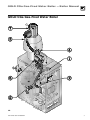
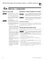
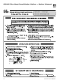
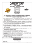
How it works . . .
x
y
z
{
|
}
~
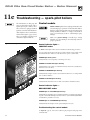
Control module
The control module (used on SPARKIGNITEDPILOTBOILERS) responds to signals from the room thermostat and
boiler limit circuit to operate the boiler circulator, pilot burner, gas valve and vent damper. When room thermostat
calls for heat, the control module starts the system circulator and activates the vent damper (causing it to drive
open).
When the vent damper has opened completely, the control module opens the pilot valve and activates pilot ignition spark.
The control module allows up to 15 seconds to establish pilot flame. If flame is not sensed within 15 seconds, the
control module will turn off the gas valve, flash the Flame light, and immediately start a new cycle. This will continue indefinitely until pilot flame is established or power is interrupted. Once pilot flame is proven, the control
module opens the gas valve to allow main burner flame.
When the room thermostat is satisfied, the control module turns off the gas valve and deactivates the vent damper
(causing it to close).
The control module indicator lights show normal sequence when the lights are on steady. When a problem occurs, the control module flashes combinations of lights to indicate the most likely reason for the problem. See
page 52 for details.
3TANDINGPILOTBOILERS (controls not shown) use the pilot thermocouple to prove flame. If the thermocouple
is satisfied, the gas valve and vent damper will open on a call for heat and close afterwards.
Transformer
The control transformer reduces line voltage to 24 volts for the gas valve and limit circuit.
Draft hood
The draft hood provides a minimum draft for the boiler, assuring adequate air for combustion if installed in accordance with manual and not modified in any way.
Spill switch
The spill switch will shut down the boiler (requiring manual reset of the switch reset button) if the vent system
becomes blocked.
Water temperature limit switch
The water temperature limit switch turns off the gas valve if the temperature in the boiler goes above its setting.
(The circulator will continue to run as long as there is a call for heat.)
Boiler circulator
The boiler circulator circulates water through the external (system) piping. The circulator is shipped loose, and can
be mounted on either the boiler supply or return piping. The factory-installed circulator wiring harness provides
ample length for either location. NOTE — The control module provides a pump exercising routine. If the boiler
is not operated for 30 days, the control module will power the circulator for 30 seconds, then turn off.
Vent damper
The vent damper closes during off cycles to reduce heat loss from the house up the vent.
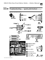
Other boiler components:
a
b
c
d
e
2
supply to system
return from system
flue outlet
burner manifold
gas valve
f
g
h
i
j
pressure/temperature gauge
relief valve
air vent connection
flame rollout switch
burner orifice
k
l
m
n
o
pilot burner, typical
stainless steel burners
cast iron boiler sections
flue collector
junction box
Part Number 550-101-009/0107
GOLD CGa Gas-Fired Water Boiler — Boiler Manual
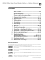
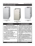
GOLD CGa Gas-Fired Water Boiler
Part Number 550-101-009/0107
3
GOLD CGa Gas-Fired Water Boiler — Boiler Manual
Contents
How is works .................................................... 2-3
Hazard definitions ............................................... 4
Please read before proceeding ............................ 5
1
Prepare boiler location ...................................6–11
2
Prepare boiler............................................... 12-15
3
Water piping ................................................. 16-25
4
Gas piping ......................................................... 26
5
Field wiring ....................................................... 27
6
Start-up ........................................................ 28-32
7
Check-out procedure ......................................... 33
8
Operation – standing pilot boilers ................. 34-36
9
Operation – spark-ignited pilot boilers .......... 37-43
10
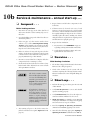
Service and maintenance ............................. 44-49
11
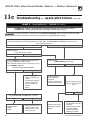
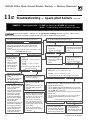
Troubleshooting:
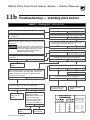
Standing pilot boilers ............................. 49-50, 51
Spark-ignited pilot boilers .................49-50, 51-59
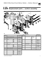
12
Replacement parts ....................................... 60-65
13
Dimensions and ratings ................................ 66-67
Hazard definitions
The following defined terms are used throughout this manual to bring attention to the presence of hazards of
various risk levels or to important information concerning the life of the product.
Indicates presence of hazards that WILL CAUSE SEVERE personal injury, death or substantial
property damage.
Indicates presence of hazards that CAN CAUSE SEVERE personal injury, death or substantial
property damage.
Indicates presence of hazards that WILLORCANCAUSEMINOR personal injury or property damage.
Indicates special instructions on installation, operation or maintenance that are important but
not related to personal injury or property damage.
4
Part Number 550-101-009/0107
GOLD CGa Gas-Fired Water Boiler — Boiler Manual
Please read before proceeding
Installer
User
2EAD ALL INSTRUCTIONS BEFORE IN
stalling. Follow all instructions in
proper order to prevent personal
injury or death.
s #ONSIDERPIPINGANDINSTALLATION when determining
boiler location.
s !NYCLAIMSFORDAMAGEORSHORTAGEINSHIPMENT
must be filed immediately against the transportation
company by the consignee.
s 4HIS MANUAL IS FOR USE ONLY BY YOUR QUALIlED
HEATINGINSTALLERSERVICETECHNICIAN
s 0LEASEREFERTOTHE5SERS)NFORMATION-ANUAL for
your reference.
s 7E RECOMMEND REGULAR SERVICE BY A QUALIlED
SERVICETECHNICIANATLEASTANNUALLY.
The boiler contains ceramic fiber and fiberglass materials. Use care when handling these
materials per instructions on page 68 of this manual. Failure to comply could result in severe
personal injury.
When calling or writing about the boiler— Please have the boiler model number from the
BOILERRATINGLABELANDTHE#0NUMBERFROMTHEBOILERJACKET9OUMAYLISTTHE#0NUMBERIN
the space provided on the )NSTALLATIONANDSERVICECERTIlCATE found on page 33.
Failure to adhere to the guidelines on this page can result in severe personal injury, death
or substantial property damage.
When servicing boiler —
s 4OAVOIDELECTRICSHOCKDISCONNECTELECTRICALSUPPLY
before performing maintenance.
s 4O AVOID SEVERE BURNS ALLOW BOILER TO COOL BEFORE
performing maintenance.
s #ONTINUALFRESHMAKEUPWATERWILLREDUCE
boiler life. Mineral buildup in sections reduces heat transfer, overheats cast iron, and
causes section failure. Addition of oxygen
and other gases can cause internal corrosion.
Leaks in boiler or piping must be repaired
at once to prevent makeup water.
Boiler operation —
s $ONOTBLOCKmOWOFCOMBUSTIONORVENTILATIONAIR
to boiler.
s 3HOULDOVERHEATINGOCCURORGASSUPPLYFAILTOSHUT
off, do not turn off or disconnect electrical supply to
circulator. Instead, shut off the gas supply at a location
external to the appliance.
s $O NOT USE THIS BOILER IF ANY PART HAS BEEN UNDER
water. Immediately call a qualified service technician to inspect the boiler and to replace any part of
the control system and any gas control that has been
under water.
s $ONOTADDCOLDWATERTOHOTBOILER4HERMAL
shock can cause sections to crack.
Boiler water —
s $O NOT USE PETROLEUMBASED CLEANING OR SEALING
compounds in boiler system. Water seal deterioration
will occur, causing leakage between sections. This can
result in substantial property damage.
s $ONOTUSEhHOMEMADECURESvORhBOILERPATENTMEDICINESv 3ERIOUS DAMAGE TO BOILER PERSONNEL ANDOR
property may result.
Part Number 550-101-009/0107
Glycol — potential fire hazard —
All glycol is flammable when exposed to high
temperatures. If glycol is allowed to accumulate
in or around the boiler or any other potential
ignition source, a fire can develop. In order to
prevent potential severe personal injury, death
or substantial property damage from fire and/or
structural damage:
s .EVERSTOREGLYCOLOFANYKINDNEARTHEBOILER
or any potential ignition source.
s -ONITORANDINSPECTTHESYSTEMANDBOILER
regularly for leakage. Repair any leaks immediately to prevent possible accumulation
of glycol.
s .EVERUSEAUTOMOTIVEANTIFREEZEORETHYLENE
glycol in the system. Using these glycols can
lead to hazardous leakage of glycol in the
boiler system.
5
GOLD CGa Gas-Fired Water Boiler — Boiler Manual
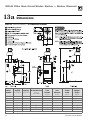
1a
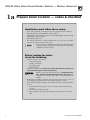
Prepare boiler location — codes & checklist
Installations must follow these codes:
s ,OCALSTATEPROVINCIALANDNATIONALCODESLAws, regulations and ordinances.
s .ATIONAL&UEL'AS#ODE!.3):nLATESTEDITION
s 3TANDARDFOR#ONTROLSAND3AFETY$EVICESFOR!UTOMATICALLY&IRED"OILERS!.3)
!3-%#3$WHENREQUIRED
s .ATIONAL%LECTRICAL#ODE
s &OR #ANADA ONLY " OR " )NSTALLATION #ODE #3! # #ANADIAN
%LECTRICAL#ODE0ARTANDANYLOCALCOdes.
4HE#'ABOILERGASMANIFOLDANDCONTROLSMETSAFELIGHTINGAND
other performance criteria when boiler underwent tests specified
IN!.3):nLATESTEDITION
Before locating the boiler,
check the following:
s #HECKFORNEARBYCONNECTIONTO
s 3YStem water piping
s 6ENTINGCONNECTIONS
s 'ASSUPPLYPIPING
s %LECtrical power
s #HECKAREAAROUNDBOILER2EMOVEANYCOMBUSTIBLEMATERIALSGASOLINEAND
OTHERmAMMABLELIQUIDSOROTHERCONTAMINANTS.
Failure to keep boiler area clear and free of COMBUSTIBLEMATE
RIALSGASOLINEANDOTHERmAMMABLELIQUIDSANDVAPORS can
result in severe personal injury, death or substantial property
damage.
s "Oiler must be installed so that gas control system components are protected
from dripping or spraying water or rain during operation or service.
s )FNew boiler will replace existing boiler, check for and correct system problems,
such as:
1. System leaks causing oxygen corrosion or section cracks from hard water
deposits.
2. Incorrectly-sized expansion tank.
3. Lack of antifreeze in boiler water causing system and boiler to freeze and
leak.
6
Part Number 550-101-009/0107
GOLD CGa Gas-Fired Water Boiler — Boiler Manual
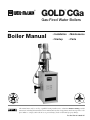
1b
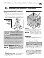
Prepare boiler location — clearances
Recommended SERVICE clearances
&IGUREB
Required MINIMUM clearances
&IGA
1. Provide clearances for cleaning and servicing the boiler and for
access to controls and components. See Figure 1a for recommendations.
2. Provide at least screwdriver clearance to jacket front panel screws
for removal of front panel for inspection and minor service. If
unable to provide at least screwdriver clearance, install unions and
&IGUREA
2ECOMMENDED
SERVICE
clearances
(see 7!2.).'
below)
Flooring
4HE#'ABOILERISAPPROVEDFORINSTALLATIONONCOMBUSTIBLE
flooring, but must never be installed on carpeting.
)F ANY CLEARANCE IS LESS THAN IN &IGURE1a
PROVIDE OPENINGS FOR COMBUSTION AND
VENTILATION AIR located on the wall or door
opposite the boiler FRONT (see Figure 1b).
These openings must be located as shown in Figure 1b to provide
proper air flow around the boiler. The free area of each opening
(after deducting for louvers) must be at least ONESQUAREINCH
PER"TUH of boiler input. If the building is of unusually
tight construction (see page 11 for definition), the air openings
must connect directly to outside or the building must have air
openings to the outside as specified on page 11.
If clearances are equal to or greater than Figure 1a, see pages 10
and 11 for location and sizing of combustion air openings.
Failure to comply can result in severe personal injury, death or
substantial property damage and reduced boiler life.
Required MINIMUM clearances
$ONOTINSTALLBOILERONCARPETINGEVEN
if foundation is used. Fire can result,
causing severe personal injury, death
or substantial property damage.
Foundation
1. Provide a solid brick or minimum 2-inch thick concrete
foundation pad if any of the following is true:
s mOORCANBECOMEmOODED
s THEBOILERMOUNTINGAREAISNOTLEVEL
2. Minimum dimensions are vLENGTH by:
Minimum foundation width:
CGa-25/3
CGa-4
CGa-5
12"
15"
18"
CGa-6
CGa-7
CGa-8
21"
24"
27"
&IGB
.EVERINSTALLTHEBOILERINASPACEWITHCLEAR
ANCESLESSTHANTHEMINIMUMCLEARANCESSHOWN
IN&IGUREB. Failure to comply can result in severe
personal injury, death or substantial property
damage and reduced boiler life.
1. (OTWATERPIPES ATLEAST56OINCH from combustible material.
2. 3INGLEWALLVENTPIPE ATLEASTINCHES from combustible material.
3. 4YPE"DOUBLEWALLMETALVENTPIPE: refer to vent manufacturer’s
recommendation for clearances to combustible material.
Part Number 550-101-009/0107
Residential garage installations
Take the following special precautions when installing the
boiler in a residential garage. If the boiler is located in a
RESIDENTIALGARAGEPER!.3):
s -OUNTTHEBOILERAMINIMUMOFINCHESABOVETHE
mOOR of the garage to assure the burner and ignition
devices will be no less than 18 inches above the floor.
s ,OCATEORPROTECTTHEBOILER so it cannot be damaged
by a moving vehicle.
7
GOLD CGa Gas-Fired Water Boiler — Boiler Manual
1c
Prepare boiler location — vent system
Failure to follow all instructions can result in flue gas spillage and carbon monoxide emissions, causing severe
personal injury or death.
Inspect existing chimney before installing boiler. Failure to clean or replace perforated pipe or tile lining will cause
severe personal injury or death.
$ONOTALTERBOILERDRAFTHOODORPLACEANYOBSTRUCTIONORNONAPPROVEDVENTDAMPERINBREECHINGORVENTSYSTEM
#3!CERTIlCATIONWILLBECOMEVOID&LUEGASSPILLAGEANDCARBONMONOXIDEEMISSIONSWILLOCCURCAUSINGSEVERE
personal injury or death.
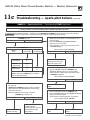
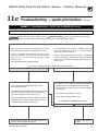
When removing boiler from an
existing common vent system:
Chimney or vent requirements
At the time of removal of an existing boiler, the following
steps shall be followed with each appliance remaining
connected to the common venting system placed in operation, while the other appliances remaining connected
to the common venting system are not in operation.
6ENTINGMUSTBEINSTALLEDACCORDINGTO0ART6ENTINGOF%QUIPMENTOF.ATIONAL&UEL'AS#ODE!.3)
:LATESTEDITIONANDAPPLICABLEBUILDINGCODES
#ANADIANINSTALLATIONSMUSTCOMPLYWITH"OR
")NSTALLATION#ODES
a. 3EALANYUNUSEDOPENINGS in the common venting
system.
2. See Ratings table on page 67 for minimum chimney
or vent sizes. A chimney or vent WITHOUTALISTED
CAP should extend ATLEASTFEETABOVETHEHIGHEST
POINT where it passes through a roof of a building
and ATLEASTFEETHIGHER than ANYPORTIONOFA
BUILDINGWITHINAHORIZONTALDISTANCEOFFEET.
A chimney or vent must not extend less than the
distances stated above.
b. 6ISUALLY INSPECT THE VENTING SYSTEM for proper
size and horizontal pitch and determine there is no
blockage or restriction, leakage, corrosion or other
deficiencies which could cause an unsafe condition.
c. 4ESTVENTSYSTEM — Insofar as is practical, close all
building doors and windows and all doors between
the space in which the appliances remaining connected to the common venting system are located
and other spaces of the building. Turn on clothes
dryers and any appliance not connected to the common venting system. Turn on any exhaust fans, such
as range hoods and bathroom exhausts, so they will
OPERATEATMAXIMUMSPEED$ONOTOPERATEASUMMEREXHAUSTFAN#LOSElREPLACEDAMPERS
d. 0LACEINOPERATION the appliance being inspected.
Follow the lighting/operating instructions. Adjust
thermostat so appliance will operate continuously.
e. 4ESTFORSPILLAGE at draft hood relief opening after
5 minutes of main burner operation. Use the flame
of a match or candle.
f. After it has been determined that EACHAPPLIANCE
remaining connected to the common venting system
properly vents when tested as outlined above, return
doors, windows, exhaust fans, fireplace dampers,
and any other gas-burning appliance to their previous conditions of use.
Any improper operation of common venting system
should be corrected so the installation conforms with
THE.ATIONAL&UEL'AS#ODE!.3):LATESTEDITION
#ORRECTBYRESIZINGTOAPPROACHTHEMINIMUMSIZEAS
determined using the appropriate tables in Part 11 of
THAT CODE #ANADIAN INSTALLATIONS MUST COMPLY WITH
"OR")NSTALLATION#ODE
8
3. A lined chimney is preferred and must be used when
required by local, state, provincial and national
CODESLAWSREGULATIONSANDORDINANCES6ITREOUSTILE
linings with joints that prevent retention of moisture
and linings made of noncorrosive materials are best.
Advice for flue connections and chimney linings can
be obtained from local gas utility. 4YPE" doublewall metal vent pipe or single-wall vent pipe may
be used as a liner.
#OLD MASONRY CHIMNEYS ALSO KNOWN AS OUTSIDE
chimneys, typically have one or more walls exposed to outside air. When any atmospheric gasfired boiler with automatic vent damper is vented
through this type of chimney, the potential exists for
CONDENSATIONTOOCCUR#ONDENSATIONCANDAMAGE
a masonry chimney. Weil-McLain recommends the
following to prevent possible damage.
a. Line chimney with corrosion-resistant metal
LINERSUCHAS!,#®SINGLEWALLSTAINLESS
STEELOR"VENT3IZELINERPER.ATIONAL&UEL
'AS#ODE!.3):LATESTEDITION
b. Provide drain trap to remove any condensate.
5. Where two or more gas appliances vent into a
common chimney or vent, equivalent area should
be ATLEASTEQUAL to area of vent outlet on largest
appliance PLUS PERCENT of vent outlet area on
additional appliance.
Part Number 550-101-009/0107
GOLD CGa Gas-Fired Water Boiler — Boiler Manual
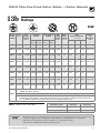
1d
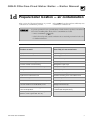
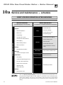
Prepare boiler location — air contamination
Please review the following information on potential
combustion air contamination problems.
Refer to 4ABLE for products and areas which may cause
contaminated combustion air.
To prevent potential of severe personal injury or death, check for products or areas listed
below before installing boiler. If any of these contaminants are found:
s REMOVECONTAMINANTSPERMANENTLY
— OR —
s ISOLATEBOILERANDPROVIDEOUTSIDECOMBUSTIONAIR3EENATIONALPROVINCIALORLOCALCODES
for further information.
4ABLE Corrosive contaminants and likely locations
Products to avoid
Areas likely to have contaminants
Spray cans containing chloro/fluorocarbons
Dry cleaning/laundry areas and establishments
Permanent wave solutions
Swimming pools
Chlorinated waxes/cleaners
Metal fabrication plants
Chlorine-based swimming pool chemicals
Beauty shops
Calcium chloride used for thawing
Refrigeration repair shops
Sodium chloride used for water softening
Photo processing plants
Refrigerant leaks
Auto body shops
Paint or varnish removers
Plastic manufacturing plants
Hydrochloric acid/muriatic acid
Furniture refinishing areas and establishments
Cements and glues
New building construction
Antistatic fabric softeners used in clothes dryers
Remodeling areas
Chlorine-type bleaches, detergents, and cleaning
solvents found in household laundry rooms
Garages with workshops
Adhesives used to fasten building products and
other similar products
Buildings under construction (where air is
contaminated with particulates)
Airborne particulates (drywall dust, fiberglass
particles, road or gravel dust, lint, etc.)
Part Number 550-101-009/0107
GOLD CGa Gas-Fired Water Boiler — Boiler Manual
1e
7
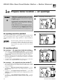
Prepare boiler location — air openings
#OMBUSTION AIR OPENING LOCATION AND SIZING
REQUIREMENTSDEPENDONTHECLEARANCESAROUND
THEBOILER#HECKTHEBOILERPLACEMENTCOMPARED
to Figure 1a, page 7.
&IGURE
Air openings to interior spaces
7
)FALLCLEARANCESAREATLEASTEQUALTO&IGUREA
PAGE, apply the sizing and placement of openings
given on pages 10 and 11.
)F!.9CLEARANCEISLESSTHAN&IGUREAPAGE,
you must provide air openings sized and located as
shown in Figure 1b, page 7. $/./4 apply the sizing
and location information shown on page 10 or 11.
&IGURE
Air openings must be provided
#OMBUSTIONAIRANDVENTILATIONOPENINGSMUSTCOMPLYTHE.ATIONAL&UEL
'AS#ODE!.3):LATESTEDITIONORAPPLICABLELOCALBUILDINGCODES
#ANADIAN INSTALLATIONS MUST COMPLY WITH " OR " )NSTALLATION
#ODES
Air directly through outside wall
7
Provide adequate combustion and ventilation air to
assure proper combustion and reduce the risk of severe
personal injury, death or substantial property damage
caused by flue gas spillage and carbon monoxide
emissions.
Air opening options
Two openings — Air supply from inside the building 7
1. If the building is of UNUSUALLYTIGHTCONSTRUCTION (see definition, next
page), the BUILDINGMUSTALSOBEPROVIDEDWITHAIROPENINGSDIRECTLY
TOTHEOUTSIDE, sized and located per Figure 3, Figure 4 or Figure 5.
"UILDINGSOFTYPICALCONSTRUCTIONSHOULDPROVIDEADEQUATECOMBUSTION
air from natural infiltration, so additional air openings to the building
are not required.
3. See Figure 2. Provide TWOOPENINGS through the interior wall, within
12 inches of the ceiling and the floor, sized per Figure 2.
Two openings — Air supply directly from outside 7
1. Air openings must be directly through an outside wall, or into a space
that connects directly to the outside (such as a ventilated attic or crawl
space, for example).
2. See Figure 3 — /PENINGSDIRECTLYTHROUGHANOUTSIDEWALL — provide
TWOOPENINGS within 12 inches of the ceiling and the floor, sized per
Figure 3.
3. See Figure 4 — !IRSUPPLIEDTHROUGHVERTICALDUCTS — provide TWO
OPENINGS terminated within 12 inches of the ceiling and the floor, sized
per Figure 4.
4. See Figure 5 — !IR SUPPLIED THROUGH HORIZONTAL DUCTS — provide
TWOOPENINGS within 12 inches of the floor and the ceiling, sized per
Figure 5.
10
&IGURE
Air from outdoors — vertical ducts
7
&IGURE
Air from outdoors — horizontal ducts
7
Part Number 550-101-009/0107
GOLD CGa Gas-Fired Water Boiler — Boiler Manual
FREE AREA of openings — the minimum areas
given in this manual are free area (equals the area,
length times width of opening, after deduction for
louver obstruction).
Use the free area information provided by the louver manufacturer.
When this information is not available, assume:
s 7OODLOUVERSASSUMEFREEAREAISOFTOTALSOTHEACTUALAREA
of each opening with wood louvers would be 5 times the required
free area.
s -ETALLOUVERSASSUMEFREEAREAISOFACTUALAREASOFORWOOD
louvers, the actual area of each opening must be 1.67 times the
required free area.
Single air opening option 7
A single combustion air opening can be used in lieu of the two-opening
options on page 10, provided:
Unusually tight construction
5NUSUALLYTIGHTCONSTRUCTIONMEANSPER!.3):
buildings in which:
a. Walls and ceilings exposed to the outside atmosphere have a continuous water vapor retarder with
a rating of 1 perm or less with openings gasketed,
and . . .
b. Weather-stripping has been added on openable
windows and doors, and . . .
C #AULKING OR SEALANTS ARE APPLIED TO AREAS SUCH AS
joints around windows and door frames, between
sole plates and floors, between wall-ceiling joints,
between wall panels, at penetrations for plumbing,
electrical, and gas lines, and in other openings.
For such construction cases, if appliances use inside air
for combustion, PROVIDEAIROPENINGSINTOTHEBUILDING
FROMOUTSIDE. Size and locate these openings per the
appropriate case in &IGUREOR on page 10.
Clearances from boiler to walls
s 4HEBOILERMUSTHAVECLEARANCESOFATLEASTTHOSESHOWNIN&IGUREA
page 7.
Opening must be directly to outside
s 4HEOPENINGMUSTCONNECTDIRECTLYTOTHEOUTDOORSORTOASPACETHAT
communicates directly to the outdoors (not to an interior space).
s 4HEAIRCANBEPROVIDEDTHROUGHADIRECTOPENINGORTHROUGHAHORIZONTAL
or vertical duct.
Opening placement
s 4HETOPOFTHEAIROPENINGMUSTBEWITHININCHESOFTHECEILING
Opening size
s 4HEFREEAREAOFTHEOPENINGMUSTBEATLEASTEQUALTOTHESUMOFTHE
area of all equipment vent connectors in the space, and . . .
s 4HEFREEAREAOFTHEOPENINGMUSTBEATLEASTSQUAREINCHPER
"TUHRINPUTRATINGOFALLEQUIPMENTLOCATEDINTHESPACE
Exception for large spaces 7
.OCOMBUSTIONAIROPENINGSARENEEDEDWHENTHEBOILERANDOTHERAPpliances) are installed in a space with a volume ATLEASTCUBICFEETPER
"TUH of all installed appliances, provided:
s THEBUILDINGMUSTNOTHAVEUNUSUALLYTIGHTCONSTRUCTION (see definition, this page)
s ALLCLEARANCESAROUNDTHEBOILERMUSTMUSTBENOLESSTHANSHOWNIN
Figure 1a, page 7.
To determine if the space is large enough to qualify:
s !DDTHETOTALINPUTOFALLAPPLIANCESIN-"(SOF"TUH
s -ULTIPLYTHISNUMBERTIMESTODETERMINEMINIMUMROOMVOLUME
s %XAMPLE&ORATOTALINPUTOF-"("TUHMINIMUM
volume is 50 x 100 = 5,000 cubic feet. At a ceiling height of 8 feet, the
space must have at least 5,000 ÷ 8 = 625 square feet (25 feet x 25 feet,
for instance).
Part Number 550-101-009/0107
Exhaust fans and air movers
The appliance space must never be under a negative
pressure, even if the appliance(s) are installed as direct
vent. Always provide air openings sized not only to the
dimensions required for the firing rate of all appliances, but also to handle the air movement rate of the
exhaust fans or air movers using air from the building
or space.
Motorized air dampers
If the air openings are fitted with motorized dampers,
electrically interlock the damper to:
s 0REVENTTHEBOILERFROMlRINGIFTHEDAMPERISNOT
fully open.
s 3HUTTHEBOILERDOWNSHOULDTHEDAMPERCLOSEDURing boiler operation.
To accomplish this interlock, wire an ISOLATEDCONTACT
(proving the damper open) in series with the thermostat input to the boiler. The boiler will not start if this
contact is open, and will shut down should it open
during operation.
11
GOLD CGa Gas-Fired Water Boiler — Boiler Manual
2a
Prepare boiler — placement and setup
Place boiler/crate near
position
1. ,EAVEBOILERINCRATEANDONPALLET until installation site is ready.
2. Move entire crate and pallet next to selected location.
3. Remove crate. ,EAVEBOILERONPALLET
4. Remove boiler from pallet as follows:
a. Tilt left side of boiler up and place a board under
left legs.
b. Tilt boiler the other way and place a board under
right legs.
c. Slide boiler backwards off pallet and into position.
$ONOTDROPBOILERORBUMPJACKET
ONmOORORPALLET$AMAGETOBOILER
can result.
#HECKLEVEL
a. Shim legs, if necessary.
B $ONOTALTERLEGS
3. Level and straighten burners.
$ONOTOPERATEBOILERWITHOUTACcess panel secured in place. Failure
to comply could cause momentary
flame rollout on ignition of main
flame, resulting in possible fire or
personal injury hazard.
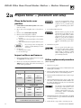
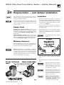
Orifice replacement procedure
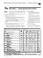
#HECK FOR CORRECTLYSIZED MANIFOLD ORIlCES 3EE
4ABLE below for sizing. (The orifice size is stamped
on the orifice spud barrel.)
(when required)
4ABLE Manifold orifice sizing
2. On gas manifold, mark location of main burner with
attached pilot assembly.
Location
Natural gas
0-2,000 ft
over 2,000 ft
2.00 mm
(Note 1)
0-2,000 ft
2,000-4,500
2.00 mm
1.90 mm
U. S.
Canada
Location
Propane gas
0-2,000 ft
over 2,000 ft
1.30 mm
(Note 1)
0-2,000 ft
2,000-4,500
1.30 mm
1.20 mm
U. S.
Canada
Note 1: For elevations above 2,000 feet, contact your
local Weil-McLain sales office for details.
12
"URNERSMUSTBEPROPERLYSEATEDIN
slots in burner rest with their openings face up. Main burner orifices
must inject down center of burner.
Failure to properly seat burners
will result in severe personal injury,
death or substantial property damage.
4. Reinstall access panel.
Inspect orifices and burners
1. Remove front jacket door. Remove base access panel
(See &IGURE, item , page 62).
#ORRECTLYSIZED MANIFOLD ORIFICES
must be used. Failure to do so will
result in severe personal injury,
death or substantial property damage.
1. Remove access panel.
3. Remove main burner with attached pilot assembly
from manifold. Remove all remaining burners.
4. Remove and discard all main burner orifices in gas
manifold.
5. Apply a small amount of pipe dope to each of the
new orifices and install in the manifold. Make sure
the orifices are aligned correctly, not cross-threaded
in the manifold tappings.
Use only pipe dope compatible with
propane gas, even if boiler is to be
operated on natural gas. Failure to
comply could result in severe personal injury, death or substantial
property damage.
6. Reinstall main burner with attached pilot assembly
at location marked on gas manifold. Reinstall all
remaining burners.
7. Follow check-out procedure, Section , page 33.
Part Number 550-101-009/0107
GOLD CGa Gas-Fired Water Boiler — Boiler Manual
2b
Prepare boiler — pressure test
Hydrostatic pressure test
Pressure test boiler BEFOREattaching water or gas piping
or electrical supply (except as noted below).
Prepare boiler for test
2EMOVE THE SHIPPING NIPPLE FROM #'A SUPPLY
tapping) and remove the boiler relief valve. 4EMPO
RARILYPLUGTHERELIEFVALVETAPPINGWITHAÐv.04
pipe plug.
2EMOVEvNIPPLEREDUCINGTEEANDDRAINVALVE
from accessory bag. Install in boiler return connection as shown on page 3 or in &IGURE, item
3, page 64. Install circulator on either the return or
supply.
2EMOVEvNIPPLEvTEEBUSHINGANDPRESsure/temperature gauge from accessory bag. Pipe
to boiler supply connection as shown in &IGURE,
page 64. (Use pipe dope sparingly.)
#ONNECTAHOSETOBOILERDRAINVALVETHEOTHEREND
connected to a fresh water supply. Make sure hose
can also be used to drain boiler after test.
#ONNECTANIPPLEANDSHUTOFFVALVETOSYSTEMSUPPLY
CONNECTIONONTHEvTEE4HISVALVEWILLBEUSED
TOBLEEDAIRDURINGTHElLL6ALVEANDNIPPLEARE
not included with boiler.)
#ONNECT A NIPPLE AND SHUTOFF VALVE TO SYSTEM
return connection (at circulator flange if circulator installed on return). This valve will be used to
BLEEDAIRDURINGTHElLL6ALVEANDNIPPLEARENOT
included with boiler.)
Fill and pressure test
1. Open the shutoff valves you installed on supply and
return connections.
2. Slowly open boiler drain valve and fresh water supply to fill boiler with water.
3. When water flows from shutoff valves, close boiler
drain valve.
Part Number 550-101-009/0107
#LOSESHUTOFFVALVES
5. Slowly reopen boiler drain valve until test pressure
of not more than 45 psi is reached on the pressure/
temperature gauge.
6. Test at no more than PSIFORNOMORETHAN
MINUTES
$O NOT LEAVE BOILER UNATTENDED.
A cold water fill could expand and
cause excessive pressure, resulting
in severe personal injury, death or
substantial property damage.
7. Make sure constant gauge pressure has been mainTAINEDTHROUGHOUTTEST#HECKFORLEAKS2EPAIRIF
found.
,EAKSMUSTBEREPAIREDATONCE.
Failure to do so can damage boiler,
resulting in substantial property
damage.
$ONOTUSEPETROLEUMBASED cleaning or sealing compounds in boiler
system. Severe damage to boiler
will occur, resulting in substantial
property damage.
Drain and remove fittings
$ISCONNECTlLLWATERHOSEFROMWATERSOURCE
$RAINBOILERATDRAINVALVEOROUTHOSEWHICHEVER
provides best access to drain. Remove hose after
draining if used to drain boiler.
3. Remove nipples and valves unless they will remain
for use in the system piping.
4. Remove plug from relief valve tapping. See Section to replace relief valve.
13
GOLD CGa Gas-Fired Water Boiler — Boiler Manual
2c
Prepare boiler — draft hood & spill switch
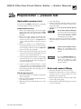
Draft hood installation
Spill switch installation
1. Orient draft hood with spill switch mounting holes to front of boiler
as shown in Figure 7.
2. Secure draft hood to outlet at top of boiler with sheet metal screws.
"OTTOMOFDRAFTHOODORhSKIRTvMUSTHAVECLEARANCEDIMENSIONABOVE
jacket top panel as indicated on draft hood.
$ONOTALTERBOILERDRAFTHOODORPLACEANYOBSTRUCTIONOR
non-approved vent damper in breeching or vent system.
#3!CERTIlCATIONWILLBECOMEVOID&LUEGASSPILLAGEAND
carbon monoxide emissions will occur causing severe
personal injury or death.
1. Fasten spill switch to draft hood as shown in &IGURE
and &IGURE.
2. See Wiring diagram to connect wires:
a. Standing pilot boiler — see PAGE.
b. Spark-ignited pilot boiler —
see PAGES and .
Improper orientation of spill switch
may cause boiler to shut down. The
loss of heat can result in significant
damage due to freezing.
Figure 6 Install spill switch
2d
Prepare boiler — install vent piping
Long horizontal vent connector,
excessive number of elbow or
tees, or other obstructions that
restrict the flow of combustion
gases should be avoided. Severe
personal injury, death or substantial property damage could
result.
14
Figure 7 Spill switch with wire harness
#ONNECTFROMDRAFTHOODORVENTDAMPEROUTLETTOCHIMNEYORVENT
with same size vent connector.
2. Where possible, vertical venting to the outside from the draft hood or
vent damper outlet will offer best performance.
7HEREHORIZONTALVENTCONNECTORISUSEDSLOPEUPWARDATLEASTvPER
lineal foot toward chimney or vent and support with hangers to prevent
sagging.
"REECHINGMUSTNOTbe connected to any portion of a mechanical draft
system that can operate under positive pressure.
Part Number 550-101-009/0107
GOLD CGa Gas-Fired Water Boiler — Boiler Manual
2e
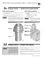
Prepare boiler — vent damper installation
These systems are used on gas-fired boilers with vent
DAMPERSASSHIPPEDFROMFACTORY"OILERWILLNOTOPERATE
without vent damper installed.
Only vent dampers listed in the Replacement parts list
ONPAGEARECERTIlEDFORUSEWITH#'ABOILERS!NY
other vent damper installed could cause severe personal
injury or death.
Damper blade
3TANDING PILOT IGNITION SYSTEMS Refer to vent
manufacturer’s instructions to install plug (shipped
with damper) in damper hole. For standing pilot boilers only, install PLUG WITH /v DIAMETER HOLE in vent
damper hole.
3PARKIGNITED PILOT SYSTEMS Refer to vent manufacturer’s instructions to install plug (shipped with
damper) in damper hole. For spark-ignited pilot boilers
only, install PLUGWITHNOHOLE in vent damper hole.
Installation
1. Install vent damper horizontally or vertically as
shown in vent damper manufacturer’s instructions.
6ENTDAMPERMUSTBEINSTALLEDSOTHATITSERVESONLY
one boiler and so damper blade indicator is visible
to the user. See &IGURE.
2. Screws or rivets used to secure the vent damper to
the draft hood must not interfere with rotation of
the damper blade.
3. Install damper harness between damper actuator
and knockout in jacket top panel. Use strain relief
connectors and locknuts to secure both ends of
damper harness.
Keep wiring harness clear of all hot
surfaces.
Minimum clearances
0ROVIDEAMINIMUMOFvBETWEENTHEVENTDAMPERAND
any combustible material. (Provide a minimum of 36"
between jacket top and combustible ceiling.)
$ONOT modify draft hood or vent damper, or make an-
other connection between draft hood and vent damper
OR BOILER EXCEPT AS NOTED BELOW 4HIS WILL VOID #3!
certification and will not be covered by Weil-McLain
warranty. Any changes will cause severe personal injury,
death or substantial property damage.
Figure 8 Vent damper assemblies
4. Read and apply the harness plug warning label
(shown above) so that it is visible after installation.
5. Plug damper harness receptacle into damper harness
plug.
"YPASSINGJUMPERINGVENTDAMPER
will cause flue products such as
carbon monoxide to escape into
the house. This will cause severe
personal injury or death.
After boiler has operated once, if either end of harness is disconnected,
the system safety shutdown will occur. The boiler will not operate until
harness is reconnected.
%FlKALOR&IELD#ONTROLSDAMPER —
$AMPERHOLDOPENSWITCHMUSTBE
in !UTOMATIC /PERATION position
for system to operate properly.
Part Number 550-101-009/0107
15
GOLD CGa Gas-Fired Water Boiler — Boiler Manual
3a
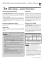
Water piping — general information
General piping information
Circulator
)FINSTALLATIONISTOCOMPLYWITH!3-%OR#ANADIANREQUIREMENTSANADditional HIGHTEMPERATURELIMIT is needed. Install control in supply piping
between boiler and isolation valve. Set second control to minimum 20°F
above setpoint of first control. Maximum allowable setpoint is 240°F. See
page 34 or 38, for wiring.
A LOWWATERCUTOFFDEVICE is required when boiler is installed above radiation level or by certain state or local codes or insurance companies. Use
low water cutoff designed for water installations. Electrode probe-type is
recommended. Purchase and install in tee in supply piping above boiler.
Use BACKmOW CHECK VALVE in cold water supply as required by local
codes.
The circulator is shipped loose (wiring pre-attached to
boiler) to allow you to locate it either in the return or
supply piping, as desired. See page 3 for a typical installation. Pipe the expansion tank to the suction side of the
circulator whenever possible. Install an air separator in
THESUPPLYPIPING#ONNECTTHEEXPANSIONTANKTOTHEAIR
separator only if the separator is on the suction side of
the circulator. Always install the system fill connection
at the same point as the expansion tank connection to
the system. &IGURES and show typical near-boiler
piping connections.
Pressure/temperature gauge
Install pressure/temperature gauge in tee on supply piping (as shown in
drawing on page 3).
Relief valve
)NSTALLRELIEFVALVEVERTICALLYINÐvTAPPINGONSIDEOFBOILER3EE &IGURE
OR, page 17, and the tag attached to the relief valve for manufacturer’s
instructions.
s
s
s
s
To avoid water damage or scalding due to relief valve
operation:
$ISCHARGELINEMUSTBECONNECTEDTORELIEFVALVEOUTLETANDRUNTOA
SAFEPLACEOFDISPOSAL. Terminate the discharge line to eliminate
possibility of severe burns should the valve discharge.
$ISCHARGELINEMUSTBEASSHORTASPOSSIBLEANDBETHESAMESIZEAS
THEVALVEDISCHARGECONNECTION throughout its entire length.
$ISCHARGELINEMUSTPITCHDOWNWARD from the valve and terminate
ATLEASTvABOVETHEmOORDRAINWHEREANYDISCHARGEWILLBECLEARLY
visible.
4HEDISCHARGELINESHALLTERMINATEPLAINNOTTHREADED, with a material serviceable for temperatures of 375°F or greater.
s $ONOTPIPETHEDISCHARGETOANYPLACEWHEREFREEZINGCOULD
OCCUR
s .OSHUTOFFVALVE shall be installed between the relief valve and boiler,
ORINTHEDISCHARGELINE$ONOTPLUGORPLACEANYOBSTRUCTIONINTHE
discharge line.
s &AILURETOCOMPLY with the above guidelines could result in failure of
the relief valve to operate, resulting in possibility of severe personal
injury, death or substantial property damage.
s 4ESTTHEOPERATIONOFTHEVALVE after filling and pressurizing system
by lifting the lever. Make sure the valve discharges freely. If the valve
fails to operate correctly, replace it with a new relief valve.
16
System water piping
See &IGURE (diaphragm-type or bladder-type expansion tank) or &IGURE (closed-type expansion tank),
and 4ABLE below, for near-boiler and single-zone
systems designed for return water at least 130°F.
3EEPAGESTOCOMPLETEMULTIPLEZONEPIPINGOR
pages 20-25 to complete piping for radiant heating
systems or converted gravity systems (large-volume
systems originally designed for circulation by natural
convection rather than a pump). See page 25 for boilers
used with refrigeration systems.
Table 3 Water pipe size (based on 20°F rise)
Boiler model
To
system
From
system
CGa-25
¾"
¾"
CGa-3, 4, 5
1"
1"
CGa-6, 7
1 ¼"
1 ¼"
CGa-8
1 ½"
1 ½"
Note: The boiler supply and return connections, the return/
drain tee and the supply/gauge tee supplied with the
boiler are 1¼” NPT. One of the circulator flanges supplied with the boiler is 1¼”. The other circulator flange
is the size of the recommended system piping shown
above.
#HILLERSORAIRHANDLINGUNITS:
Install boiler such that —
s #HILLEDMEDIUMIFUSEDISPIPEDINPARALLELWITH
heating boiler. Use appropriate valves to prevent
CHILLED MEDIUM FROM ENTERING BOILER #ONSULT
)"2)NSTALLATIONAND0IPING'UIDES
s )F BOILER IS CONNECTED TO HEATING COILS LOCATED IN
air handling units where they can be exposed to
refrigerated air, use flow control valves or other automatic means to prevent gravity circulation during
COOLINGCYCLE#IRCULATIONOFCOLDWATERTHROUGHTHE
boiler could result in damage to the heat exchanger,
causing possible severe personal injury, death or
substantial property damage.
Part Number 550-101-009/0107
GOLD CGa Gas-Fired Water Boiler — Boiler Manual
3b
Water piping — single-zone system
Undersized expansion tanks cause system water to be lost from relief valve and makeup water
to be added through fill valve. Eventual section failure can result.
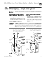
Diaphragm-type or bladdertype expansion tank (Figure 9)
Closed-type expansion tank
1. Ensure expansion tank size will handle boiler and
system water volume and temperature. Tank must
be located in boiler return piping as close to boiler
as possible, before inlet side of circulator. See tank
manufacturer’s instructions for details.
1. Ensure expansion tank size will handle boiler and
system water volume and temperature. See tank
manufacturer’s instructions for details.
2. Install an AUTOMATICAIRVENT as shown.
(Figure 10)
#ONNECTTANKTO v.04TAPPINGLOCATEDBEHIND
SUPPLY OUTLET USING v .04 PIPING 0ITCH ANY
horizontal piping up towards tank 1 inch per 5 feet
of piping.
Use &IGURE or &IGURE only for single-zone systems designed forRETURNWATERATLEAST
& For systems with low return water temperature possible, such as converted gravity
systems and radiant heating systems, refer to the special piping suggestions of pages 20-25.
Failure to prevent low return water temperature to the boiler could cause corrosion of the
boiler sections or burners, resulting in severe personal injury, death or substantial property
damage.
&IGURE
Part Number 550-101-009/0107
Diaphragm- or bladder-type expansion
tank — Single-zone system using diaphragm-type or bladder-type expansion
tank. See Table 3 for piping sizes.
&IGURE
Closed-type expansion tank — Singlezone system using closed-type expansion tank. See Table 3 for piping sizes.
17
GOLD CGa Gas-Fired Water Boiler — Boiler Manual
3c
Water piping — multiple zones
Piping multiple zones
Follow instructions on pages 16 and 17 to install nearboiler or single-zone piping. (Also refer to 0IPINGFOR
RADIANTHEATINGSYSTEMSORCONVERTEDGRAVITYSYS
TEMS below, if applicable.)
See &IGURE or &IGUREPAGETOCOMPLETEIN-
stallation.
Zoning with circulators (Figure 11)
(return temp over 130°F)
1. Size each circulator to individual circuit requirements.
$ONOTINSTALLCIRCULATORONBOILEREXCEPTFORPRImary/secondary piping).
3. Install isolation (balancing) valves to adjust flow to
distribute heat to all zones.
4. Install and wire a separate relay for each zone circulator.
Zoning with zone valves (Figure 12)
(return temp over 130°F)
1. Install isolation (balancing) valves to adjust flow to
distribute heat to all zones.
2. Provide a separate 24-volt transformer to power the
zone valves. Size the transformer to handle the total
rated load of all connected zone valves.
Piping for radiant heating
systems or converted gravity
systems
Converted gravity (or steam) systems
Whenever possible, use the primary/secondary piping
shown in &IGURES or on page 21. This piping design allows changing boiler flow rate without affecting
primary circuit flow rate.
If &IGURES or cannot be used, use the boiler-bypass
piping shown in &IGURE or &IGURE ONPAGE9OU
can also use the piping shown in &IGURE on page 25
(system-bypass), if the reduced flow rate in the heating
system will not cause heat distribution problems.
Failure to prevent low return water
temperature to the boiler could
cause corrosion of the boiler sections or burners, resulting in severe
personal injury, death or substantial
property damage.
Radiant heating systems
Preferably, use primary/secondary piping, as shown
in &IGURESor on page 21. Alternatively, use the
method of either &IGURE or &IGURE on page 23.
$ONOTUSETHEPIPINGOF&IGURE (system-bypass),
because this method does not control radiant system
supply temperature.
If radiant system tubing has no oxygen barrier, a HEAT
EXCHANGERmust be used.
Radiant heating system piping should include a means of regulating the boiler return water
temperature and the system supply temperature (such as provided by an injection pumping
CONTROL"OILERRETURNWATERTEMPERATUREWILLBEADEQUATELYCONTROLLEDUSINGTHEMETHODS
shown in this manual provided the system supply temperature is relatively constant.
$/./4 apply the methods in this manual if the system is equipped with an OUTDOORRESET
CONTROL. Instead, provide controls and piping which can regulate the boiler return water
TEMPERATUREATNOLESSTHAN®ARDLESSOFSYSTEMSUPPLYTEMPERATURE#ONTACTYOUR
Weil-McLain representative for suggested piping and control methods. Failure to prevent
cold return water temperature to the boiler could cause corrosion damage to the sections
or burners, resulting in possible severe personal injury, death or substantial property damage.
18
Part Number 550-101-009/0107
GOLD CGa Gas-Fired Water Boiler — Boiler Manual
3c
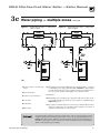
Water piping — multiple zones
&IGURE
Zoning with circulators — return water
130°F or higher.
1 "OILER ISOLATION BALANCING
valves
&IGURE
(continued)
Zoning with zone valves — return water
130°F or higher.
10 Automatic air vent (with diaphragm-type expansion tank), or connect
to tank fitting (closed-type expansion tank). $/./4 use an automatic
air vent when using closed-type expansion tank. It would allow air to
leave the system, causing waterlogging of the expansion tank.
2 Flow/check valve
3 System or zone circulator
11 Fill valve
12 $IAPHRAGMTYPEORBLADDERTYPEEXPANSIONTANKIFUSED&ORCLOSED
5 :ONEVALVE
type expansion tank, pipe from top of air separator to tank fitting as in
&IGURE, page 17.)
6 $RAINVALVE
13 !IRSEPARATORANDAUTOMATICVENTIFUSED.OTETHATTHElLLVALVEMUST
9 Relief valve
always be connected to the expansion tank, regardless of location of
expansion tank circulator or air separator.
For systems with possible low return-water temperature (such as converted gravity systems,
radiant heating systems and heat pump systems), refer to the special piping suggestions of
&IGURESn, as applies. Failure to prevent sustained low return water temperature to
the boiler could cause corrosion of the boiler sections, resulting in severe personal injury,
death or substantial property damage.
Part Number 550-101-009/0107
GOLD CGa Gas-Fired Water Boiler — Boiler Manual
3d
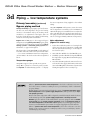
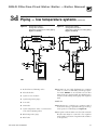
Piping — low temperature systems
Primary/secondary (preferred)
Bypass piping method
0RIMARYSECONDARYbypass piping is preferred because
the flow rate and temperature drop in the heating
circuit(s) is determined only by the heating circuit
circulator(s). So adjustment of the bypass valves in
the boiler circuit will not cause a change in the heating
circuit rate and temperature distribution.
Figures 13 and 14, page 21, show suggested bypass
arrangements using PRIMARYSECONDARY bypass piping
(preferred) for low temperature systems such as RADIANT
HEATINGSYSTEMS or CONVERTEDGRAVITYSYSTEMS. For
alternatives, see pages 22 through 25.
The bypass valves (items A and B) provide mixing of
hot boiler outlet water with cooler system return water
— set to assure a minimum return water temperature
(at least 130°F) to the boiler. Set the valves as explained
below.
Temperature gauges
'AUGEA is suggested, but optional on any system.
'AUGE B is optional on converted gravity systems,
but REQUIREDon radiant heating systems — to display
20
the water temperature being supplied to the radiant
tubing.
'AUGE is REQUIREDon all systems to assure the return
water temperature is accurately set for a minimum of
130°F. If this gauge is not available however, adjust the
valves such that the boiler-mounted temperature/pressure gauge reads at least 150°F when the system return
water is cold (approximately 60°F water temperature).
Valve adjustment
(Figures 13 and 14 only)
1. Set the valves while the system is cool, setting for the
coldest expected water temperature (usually 60°F
since the system will often drop to room temperature between cycles).
2. Start with valve A fully closed and B fully open.
'RADUALLYOPENVALVEA while closing valve B until
the temperature at gauge reads 130°F when gauge
A reads 60°F.
.OTETHATVALVEA regulates the amount of hot water from the boiler supply which mixes with return
WATER6ALVEB regulates the amount of system water
flowing through the boiler secondary loop.
Failure to PREVENTLOWRETURNWATERTEMPERATURE to the boiler could cause corrosion of
the boiler sections or burners, resulting in severe personal injury, death or substantial
property damage.
Radiant heating system piping should include a means of REGULATINGTHEBOILERRETURN
WATERTEMPERATURE and the SYSTEMSUPPLYTEMPERATURE (such as provided by an INJEC
TIONPUMPINGCONTROL).
"OILERRETURNWATERTEMPERATUREWILLBEADEQUATELYCONTROLLEDUSINGTHEMETHODSSHOWN
in this manual provided the SYSTEMSUPPLYTEMPERATURE is RELATIVELYCONSTANT
DO NOT apply the methods of this manual if the system is equipped with an OUTDOOR
RESETCONTROL Instead, PROVIDECONTROLSANDPIPING which can REGULATETHEBOILERRE
TURNWATERTEMPERATURE at NOLESSTHAN& regardless of system supply temperature.
#ONTACTYOUR7EIL-C,AINREPRESENTATIVEFORSUGGESTEDPIPINGANDCONTROLMETHODS
Failure to PREVENTCOLDRETURNWATERTEMPERATURE to the boiler could cause corrosion
damage to the sections or burners, resulting in possible severe personal injury, death or
substantial property damage.
Part Number 550-101-009/0107
GOLD CGa Gas-Fired Water Boiler — Boiler Manual
3d
Piping — low temperature systems
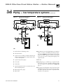
&IGURE
Primary/secondary piping
Zoning with circulators
1 "OILERISOLATIONBALANCINGVALVES
2
Flow/check valve
3
System or zone circulator (circulator should cycle
with zone valve and switches, using circulator valve
or zone control panel)
4
System temperature gauges
5 :ONEVALVE
6 $RAINVALVE
7
System temperature valves (see instructions to the
left for adjusting valves)
8 "LENDTEMPERATUREGAUGE
9
Relief valve
Part Number 550-101-009/0107
&IGURE
(continued)
Primary/secondary piping
Zoning with zone valves
10 Automatic air vent (with diaphragm-type expansion
tank), or connect to tank fitting (closed-type expansion tank). DO NOT use an automatic air vent when
using closed-type expansion tank. It would allow
air to leave the system, causing waterlogging of the
expansion tank.
11 Fill valve
12 $IAPHRAGMTYPE OR BLADDERTYPE EXPANSION TANK
if used (For closed-type expansion tank, pipe from
top of air separator to tank fitting as in &IGURE,
page 17.)
13 !IRSEPARATORANDAUTOMATICVENTIFUSED.OTETHAT
the fill valve must always be connected to the expansion tank, regardless of location of expansion tank,
circulator or air separator.)
21
GOLD CGa Gas-Fired Water Boiler — Boiler Manual
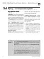
3d
Piping — low temperature systems
BOILER-bypass piping
method
This piping method (&IGURE or , page 23) is called
a BOILERBYPASS because part of the circulator flow is
bypassed around the boiler (through valve A). This
method reduces the flow rate throughout the boiler, in
order to raise the average water temperature in the boiler
ENOUGHTOPREVENTmUEGASCONDENSATION"OILERBYPASS
PIPINGISEFFECTIVEFORSOMEBOILERSINCLUDINGTHE#'A
— provided the flow rates are adjusted according to the
instructions following.
&IGURES and are alternative piping suggestions
for CONVERTED GRAVITY (large water content or steam
systems) or RADIANTHEATINGSYSTEM — for use when
primary/secondary piping can’t be applied. (&IGURE,
page 25, is another alternative, using system bypass in
place of boiler-bypass piping. &IGURE however, is
not suitable for radiant heating applications because it
does not protect the radiant system from possible high
water temperature.)
"OILERBYPASSPIPINGKEEPSSYSTEMmOWRATEASHIGHAS
possible and temperature drop as low as possible, helping to equalize the building heat distribution.
Temperature gauges
'AUGE A is optional if the bypass valves will be adjusted using cold (or room temperature) return water
22
(continued)
to the boiler. (When setting the valves without gauge
A installed — using cold or room temperature water
— assume the return water temperature to be 60°F. Set
the valves so gauge reads at least 120°F.
'AUGE B is optional on converted gravity systems,
but REQUIRED on radiant heating systems — to display
the water temperature being supplied to the radiant
tubing.
'AUGE is REQUIRED on all systems to assure reliable
adjustment of the bypass valves. The boiler-mounted
temperature/pressure gauge can be used if a separate
temperature gauge is not installed.
Valve adjustment
1. Start with valve A fully closed and B fully open.
'RADUALLY OPEN VALVE A while closing valve B
until the temperature at gauge reads 60 °F higher
than gauge A. A minimum 60°F temperature rise
through the boiler assures a low enough flow rate
and high enough average temperature to prevent
condensation even with low system return water
temperature.
6ALVEA regulates the system flow rate, while valve
Bregulates the boiler flow rate.
4. The boiler-mounted temperature/pressure gauge
may be used in place of a separate gauge .
Failure to PREVENTLOWRETURNWATERTEMPERATURE to the boiler could cause corrosion of
the boiler sections or burners, resulting in severe personal injury, death or substantial
property damage.
Radiant heating system piping should include a means of REGULATINGTHEBOILERRETURN
WATERTEMPERATURE and the SYSTEMSUPPLYTEMPERATURE (such as provided by an INJEC
TIONPUMPINGCONTROL).
"OILERRETURNWATERTEMPERATUREWILLBEADEQUATELYCONTROLLEDUSINGTHEMETHODSSHOWN
in this manual provided the SYSTEMSUPPLYTEMPERATURE is RELATIVELYCONSTANT
DO NOT apply the methods of this manual if the system is equipped with an OUTDOOR
RESETCONTROL Instead, PROVIDECONTROLSANDPIPING which can REGULATETHEBOILERRE
TURNWATERTEMPERATURE at NOLESSTHAN& regardless of system supply temperature.
#ONTACTYOUR7EIL-C,AINREPRESENTATIVEFORSUGGESTEDPIPINGANDCONTROLMETHODS
Failure to PREVENTCOLDRETURNWATERTEMPERATURE to the boiler could cause corrosion
damage to the sections or burners, resulting in possible severe personal injury, death or
substantial property damage.
Part Number 550-101-009/0107
GOLD CGa Gas-Fired Water Boiler — Boiler Manual
3d
Piping — low temperature systems
&IGURE
Boiler-bypass piping
Zoning with circulators
(Alternative to primary/secondary piping
Figures 13 and 14)
1 "OILERISOLATIONBALANCINGVALVES
2
Flow/check valve
3
System or zone circulator
4
System temperature gauges
5 :ONEVALVE
6 $RAINVALVE
7
System temperature valves (see instructions
to the left for adjusting valves)
8 "LENDTEMPERATUREGAUGE
9
Relief valve
Part Number 550-101-009/0107
&IGURE
(continued)
Boiler-bypass piping
Zoning with zone valves
(Alternative to primary/secondary piping
Figures 13 and 14)
10 Automatic air vent (with diaphragm-type expansion
tank), or connect to tank fitting (closed-type expansion tank). DO NOT use an automatic air vent when
using closed-type expansion tank. It would allow air to
leave the system, causing waterlogging of the expansion
tank.
11 Fill valve
12 $IAPHRAGMTYPE OR BLADDERTYPE EXPANSION TANK IF
used (For closed-type expansion tank, pipe from top
of air separator to tank fitting as in &IGURE)
13 !IRSEPARATORANDAUTOMATICVENTIFUSED.OTETHATTHE
fill valve must always be connected to the expansion
tank, regardless of location of expansion tank, circulator
or air separator.)
23
GOLD CGa Gas-Fired Water Boiler — Boiler Manual
3d
Piping — low temperature systems
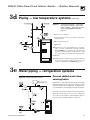
SYSTEM-bypass piping
method
This piping method (&IGURE, page 25) is called a SYS
TEMBYPASS because part of the circulator flow bypasses
the system (through valve A). This bypassed hot water
from the boiler outlet mixes with cooler system return
water temperature in order to provide minimum 130°F
RETURNWATERTOTHEBOILER6ALVEB will most often be
full open, but may need to be slightly closed on some
low pressure drop systems in order to cause enough
flow through valve A.
&IGURE is an alternative piping method that provides
return water temperature control for boilers installed
on CONVERTED GRAVITY SYSTEMS (large water content
or steam systems).
$/ ./4 apply the piping of &IGURE on RADIANT
HEATING SYSTEMS. It provides no method of regulating the water temperature provided to the system and
could result in excessive water temperature in the radiant tubing.
System-bypass piping as shown in &IGURE can be used
with either zone valve or circulator zoning. When used
with circulator zoning however, the boiler circulator
(item), must be piped as shown. It cannot be used as
one of the zoning circulators.
24
(continued)
$/ ./4 apply system-bypass piping if the reduced
flow in the system could cause poor heat distribution.
That is, system-bypass piping reduces the flow in the
system and increases the water temperature supplied to
the system. This can cause increased heat from radiators
at the beginning of the system and reduced heat from
radiators near the end of the system.
Valve adjustment
1. Start with valve A fully closed and B fully open.
'RADUALLYOPENVALVEA while closing valve B until
the temperature at gauge reads at least 130°F at all
times.
6ALVEA regulates the amount of boiler supply water
MIXEDWITHRETURNWATER6ALVEBcauses a pressure
drop in the system needed to balance flow through
valve A and the system.
4. The valve adjustment should be done with the
system at the coldest expected temperature (60°F
for converted gravity systems or high mass radiant
systems).
Failure to PREVENTLOWRETURNWATERTEMPERATURE to the boiler could cause corrosion of
the boiler sections or burners, resulting in severe personal injury, death or substantial
property damage.
Radiant heating system piping should include a means of REGULATINGTHEBOILERRETURN
WATERTEMPERATURE and the SYSTEMSUPPLYTEMPERATURE (such as provided by an INJEC
TIONPUMPINGCONTROL).
"OILERRETURNWATERTEMPERATUREWILLBEADEQUATELYCONTROLLEDUSINGTHEMETHODSSHOWN
in this manual provided the SYSTEMSUPPLYTEMPERATURE is RELATIVELYCONSTANT
DO NOT apply the methods of this manual if the system is equipped with an OUTDOOR
RESETCONTROL Instead, PROVIDECONTROLSANDPIPING which can REGULATETHEBOILERRE
TURNWATERTEMPERATURE at NOLESSTHAN& regardless of system supply temperature.
#ONTACTYOUR7EIL-C,AINREPRESENTATIVEFORSUGGESTEDPIPINGANDCONTROLMETHODS
Failure to PREVENTCOLDRETURNWATERTEMPERATURE to the boiler could cause corrosion
damage to the sections or burners, resulting in possible severe personal injury, death or
substantial property damage.
Part Number 550-101-009/0107
GOLD CGa Gas-Fired Water Boiler — Boiler Manual
3d
Piping — low temperature systems
&IGURE
(continued)
System-bypass piping — Zoning with
zone valve or circulators, return water
130°F or higher — (Alternative to boilerbypass piping Figures 15 and 16,
page 23)
3 System or zone circulator
7 System temperature valves (see instructions to the left for
adjusting valves)
8 "LENDTEMPERATUREGAUGE
9 Relief valve
10 Automatic air vent (with diaphragm-type expansion
tank), or connect to tank fitting (closed-type expansion
tank). $/./4 use an automatic air vent when using
closed-type expansion tank. It would allow air to leave
the system, causing waterlogging of the expansion tank.
11 Fill valve
12 $IAPHRAGMTYPEORBLADDERTYPEEXPANSIONTANKIFUSED
(For closed-type expansion tank, pipe from top of air
separator to tank fitting as in &IGURE, page 17.)
3e
Water piping — refrigeration systems
&IGURE Piping refrigeration systems
Prevent chilled water from
entering boiler
Install boiler so that chilled medium is piped in parallel
with the heating boiler. Use appropriate valves to prevent
chilled medium from entering boiler. See Figure 18 for
typical installation of balancing valve and check valve.
If boiler is connected to heating coils located in air handling units where they can be exposed to refrigerated
air, use flow control valves or other automatic means to
prevent gravity circulation during cooling cycle.
Part Number 550-101-009/0107
25
GOLD CGa Gas-Fired Water Boiler — Boiler Manual
4
Gas piping
Connect gas supply piping to boiler
Natural Gas:
1. Remove jacket front panel and refer to &IGURE to pipe gas to boiler.
1. Refer to 4ABLEFORPIPELENGTHANDDIAMETER"ASE
on rated boiler input (divide by 1,000 to obtain cubic
feet per hour). 4ABLE is only for gas with SPECIlC
a. )NSTALLDRIPLEG at inlet of gas connection to boiler. Where local
utility requires drip leg to be extended to the floor, use appropriate length of pipe between cap and tee.
b. )NSTALLGROUNDJOINTUNION for servicing, when required.
c. )NSTALLMANUALSHUTOFFVALVE in gas supply piping outside boiler
jacket when required by local codes or utility requirements.
d. )N#ANADA — When using manual main shutoff valve, it MUSTBE
IDENTIlED by the installer.
2. 3UPPORTPIPING with hangers, not by boiler or its accessories.
3. 0URGEALLAIR from gas supply piping.
"EFOREPLACINGBOILERINOPERATIONCHECKBOILERANDITSGASCONNEC
TIONFORLEAKS.
a. #LOSEMANUALMAINSHUTOFFVALVE during any pressure testing at
LESSTHANvWC
b. $ISCONNECTBOILERANDGASVALVEFROMGASSUPPLYPIPING durINGANYPRESSURETESTINGGREATERTHANvWC
$ONOTCHECKFORGASLEAKSWITHANOPENmAME —
Use bubble test. Failure to use bubble test or check for
gas leaks can cause severe personal injury, death or
substantial property damage.
5. 5SE PIPE DOPE COMPATIBLE WITH PROPANE GASES Apply sparingly
only to male threads of pipe joints so that pipe dope does not block gas
flow.
&AILURETOAPPLYPIPEDOPE as detailed above can result
in severe personal injury, death or substantial property
damage.
SIZINGINFORMATIONREFERTO!.3):OR"
OR"FOR#ANADIANINSTALLATIONS
2. Inlet pressure required at gas valve inlet:
s -AXIMUMvWC
s -INIMUMvWC
s -ANIFOLDGASPRESSUREvWC
)NSTALLLOCKUPGASPRESSUREREGULATORINSUPPLY
line IFINLETPRESSUREEXCEEDSvWC Adjust for
vWCMAXIMUM
Propane Gas:
#ONTACTGASSUPPLIERTOSIZEPIPESTANKSAND
lockup gas pressure regulator.
2. Adjust propane supply regulator provided by gas
SUPPLIERFORvWCMAXIMUMPRESSURE
3. Inlet pressure required at gas valve inlet:
s -AXIMUMvWC
s -INIMUMvWC
s -ANIFOLDGASPRESSUREvWC
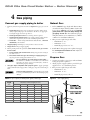
&IGURE Gas supply piping
Table 4 Pipe capacity for 0.60 specific gravity natural gas
Capacity of pipe for pipe size of:
(Capacity in cubic feet gas per hour)
Gas pipe
length
(feet)
½"
¾"
1"
1¼"
1½"
10
132
278
520
1050
1600
20
92
190
350
730
1100
30
73
152
285
590
860
40
63
130
245
500
760
50
56
115
215
440
670
26
GRAVITYWITHAPRESSUREDROPTHROUGHTHE
GAS PIPING OF v WC For additional gas pipe
75
45
93
175
360
545
100
38
79
150
305
460
150
31
64
120
250
380
Part Number 550-101-009/0107
GOLD CGa Gas-Fired Water Boiler — Boiler Manual
5
Field wiring
For your safety, TURN OFF ELECTRICAL POWER SUPPLY AT
SERVICEENTRANCEPANELBEFOREMAKINGANYELECTRICAL
CONNECTIONS to avoid possible electric shock hazard.
Failure to do so can cause severe personal injury or
death.
7IRINGMUSTBE.%##LASS
If rollout thermal fuse element wire as supplied with
boiler must be replaced, type # wire or equivalent
must be used. If other original wiring as supplied with
boiler must be replaced, use only type # wire or
equivalent.
"OILERMUSTBE ELECTRICALLY GROUNDED as required by
.ATIONAL %LECTRICAL #ODE !.3).&0! LATEST EDItion.
Installation must comply
with:
.ATIONAL %LECTRICAL #ODE AND ANY OTHER NATIONAL
state, provincial or local codes or regulations.
)N #ANADA #3! # #ANADIAN %LECTRICAL #ODE
Part 1, and any local codes.
Thermostat
#ONNECTTHERMOSTATASSHOWNONWIRINGDIAGRAM
on boiler.
2. Install on inside wall away from influences of drafts,
hot or cold water pipes, lighting fixtures, television,
sunrays or fireplaces.
3. If thermostat has a heat anticipator, set heat anticipator in thermostat to match power requirements
of equipment connected to it. If connected directly
to boiler, set for 0.1 amps plus gas valve current.
See information on the wiring diagram shown in
&IGURE B PAGE &OR OTHER DEVICES REFER TO
manufacturer’s specifications. Wiring diagram on
boiler gives setting for control module and gas valve.
Also see instructions with thermostat.
Junction box (furnished)
#ONNECT6!#POWERWIRING&IGURE).
2. Fused disconnect or service switch (15 amp. recommended) may be mounted on this box. For those
installations with local codes which prohibit installation of fused disconnect or service switch on boiler,
install a 2 x 4 cover plate on the boiler junction box
and mount the service switch remotely as required
by the code.
Wiring connections
Wiring multiple zones
"OILERISSHIPPEDWITHCONTROLSCOMPLETELYWIREDEXCEPT
spill switch and vent damper. Refer to wiring diagrams
shown on page 34 for standing pilot ignition boiler or
page 38 for spark-ignited pilot boiler.
Refer to zone valve manufacturer’s literature for wiring
and application. A separate transformer is required to
POWERZONEVALVES:ONINGWITHCIRCULATORSREQUIRESA
relay for each circulator.
&IGURE
Field wiring connections —
service switch and thermostat
(or end switch) provided by
installer
Part Number 550-101-009/0107
27
GOLD CGa Gas-Fired Water Boiler — Boiler Manual
6a
Start-up — preparation
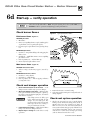
Check for gas leaks
"EFORESTARTINGTHEBOILERANDDURing initial operation, smell near the
floor and around the boiler for gas
ODORANT OR ANY UNUSUAL ODOR $O
not proceed with start-up if there is
any indication of a gas leak. Repair
any leak at once.
0ROPANEBOILERSONLY9OURPROpane supplier mixes an odorant with
the propane to make its presence
detectable. In some instances, the
odorant can fade and the gas may
no longer have an odor.
s 0ROPANE GAS CAN ACCUMULATE
at floor level. Smell near the
floor for the gas odorant or any
unusual odor. If you suspect a
leak, do not attempt to light the
pilot.
s 5SE CAUTION WHEN ATTEMPTING
to light the propane pilot. This
should be done by a qualified
service technician, particularly
if pilot outages are common.
s 0ERIODICALLY CHECK THE ODORANT
level of your gas.
28
Determine if water treatment is needed
$O NOT USE PETROLEUMBASED CLEANING OR SEALING
COMPOUNDS in boiler system. Severe damage to boiler
will occur, resulting in substantial property damage.
%LIMINATE ALL SYSTEM LEAKS #ONTINUAL FRESH MAKEUP
water will reduce boiler life. Minerals can build up in
sections, reducing heat transfer, overheating cast iron,
and causing section failure.
Verify water chemistry
#ONSULTLOCALWATERTREATMENTCOMPANIESFORUNUSUALLYHARDWATERAREAS
ABOVEGRAINSHARDNESSORLOWP(WATERCONDITIONSBELOW"OILER
WATERP(OFTOISRECOMMENDED
Freeze protection (when used)
Use antifreeze made especially for hydronic systems. Inhibited propylene
glycol is recommended.
$ONOTUSEETHYLENEGLYCOLAUTOMOTIVEORUNDILUTED
ANTIFREEZE. Severe personal injury or death can result.
$ETERMINE ANTIFREEZE QUANTITY according to system water content.
"OILERWATERCONTENTISLISTEDONPAGE2EMEMBERTOINCLUDEEXPANsion tank water content.
2. Follow antifreeze manufacturer’s instructions.
s )NSPECTBOILERANDSYSTEMATLEAST
yearly to make sure all gas piping
is leak-tight.
!SOLUTIONOFPROPYLENEGLYCOLWATERPROVIDESMAXIMUMPROTECtion to about -30°F.
s #ONSULT YOUR PROPANE SUPPLIER
regarding installation of a gas
leak detector. There are some
products on the market intended
FOR THIS PURPOSE 9OUR SUPPLIER
may be able to suggest an appropriate device.
4. Local codes may require BACKmOWPREVENTER or actual disconnect from
city water supply.
5. When using antifreeze in a system with automatic fill, install a water
METERTOMONITORWATERMAKEUP'LYCOLWILLLEAKBEFORETHEWATERBEgins to leak, causing glycol level to drop. Added water will dilute the
antifreeze, reducing the freeze protection level.
Part Number 550-101-009/0107
GOLD CGa Gas-Fired Water Boiler — Boiler Manual
6a
Start-up — preparation
(continued)
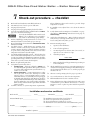
Fill the system with water
Inspect system water piping
#LOSEMANUALANDAUTOMATICAIRVENTS and boiler drain cock.
After filling the boiler and system with water, INSPECTALL
PIPING throughout the system for leaks. If found, repair
immediately. Repeat this inspection after the boiler has
been started and the system has heated up.
2. &ILLTOCORRECTSYSTEMPRESSURE#ORRECTPRESSUREWILLVARYWITHEACH
application. Typical cold water fill pressure for a residential system is
12 psi.
3. 0URGEAIR from system:
A #ONNECTAHOSETOTHEPURGEVALVESEEdrain valves, item , in suggested piping diagrams on pages 17 through 23, &IGURE through
&IGURE). Route hose to an area where water can drain and be
seen.
B #LOSETHEBOILERORSYSTEMISOLATIONVALVEBETWEENTHEPURGEVALVE
and fill connection to the system.
C #LOSEZONEISOLATIONVALVES
d. Open quick-fill valve on cold water makeup line.
e. Open purge valve.
f. One zone at a time, open the isolation valves. Allow water to run
through the zone, pushing out the air. Run until no noticeable air
mOWISPRESENT#LOSETHEZONEISOLATIONVALVESANDPROCEEDWITHTHE
next zone. Follow this procedure until all zones are purged.
G #LOSETHEQUICKlLLWATERVALVEANDPURGEVALVEANDREMOVETHE
hose. Open all isolation valves. Watch that system pressure rises to
correct cold-fill pressure.
h. After the system has operated for a while, eliminate any residual air
by using the manual air vents located throughout the system.
i. If purge valves are not installed in system, open manual air vents in
SYSTEMONEATATIMEBEGINNINGWITHLOWESTmOOR#LOSEVENTWHEN
water squirts out. Repeat with remaining vents.
4. Open AUTOMATICAIRVENT (diaphragm-type or bladder-type expansion
tank systems only) one turn.
5. Open other vents:
a. Starting on the lowest floor, open air vents one at a time until water
squirts out.
b. Repeat with remaining vents.
,EAKSMUSTBEREPAIREDATONCE
Failure to do so can damage the
boiler, resulting in substantial property damage.
$O NOT USE PETROLEUMBASED
CLEANING OR SEALING COMPOUNDS
in boiler system. Severe damage to
boiler will occur, resulting in substantial property damage.
Inspect base insulation
The boiler contains ceramic fiber
and fiberglass materials. Use care
when handling these materials per
instructions on PAGE of this
manual. Failure to comply could
result in severe personal injury.
&AILURETO REPLACE damaged insulation or reposition insulation can
result in a fire hazard, causing severe
personal injury, death or substantial
property damage.
6. Refill to correct pressure.
#HECKTOMAKESUREBASEINSULATIONISSECUREagainst
all four sides of the base. If insulation is damaged or
displaced, DONOT operate boiler. Replace or reposition
insulation.
Part Number 550-101-009/0107
GOLD CGa Gas-Fired Water Boiler — Boiler Manual
6b
Start-up — operate boiler
$/./4 proceed with boiler operation unless boiler
and system have been filled with water and all instructions and procedures of previous manual sections have
been completed. Failure to do so could result in severe
personal injury, death or substantial property damage.
"EFORESTARTINGTHEBOILERDOTHEFOLLOWING
s 2EADMANUAL 3ECTION and the ,IGHTING/PERATING INSTRUCTION
procedure (see 4ABLE, below).
s 6ERIFYTHEBOILERANDSYSTEMAREFULLOFWATER.
s 6ERIFYTHE 3TARTUPPREPARATION procedures of 3ECTION have been
completed.
4ABLE Lighting/Operating instruction location guide
Models Standing pilot
CGa-25
to
CGa-6
CGa-7
to
CGa-8
30
Gas
Page Spark-ignited pilot
Natural or
Honeywell VR8200/VR8300
Propane
35
Robertshaw 7200
Natural
36
Honeywell VR8200/VR8300
Natural or
Propane
Robertshaw 7200
Natural
Gas
Page
Honeywell VR8204/VR8304 Natural
40
Robertshaw 7200
Natural
41
White-Rodgers 36E
Natural
42
35
Honeywell VR8204/VR8304 Natural
40
36
White-Rodgers 36C
43
Natural
Part Number 550-101-009/0107
GOLD CGa Gas-Fired Water Boiler — Boiler Manual
6b
Start-up — operate boiler
(continued)
Start the boiler
s &OLLOWTHE,IGHTING/PERATING)NSTRUCTIONS from
3ECTION OR to start the boiler. Remove boiler
jacket door and note the gas valve manufacturer
and model number. Use only the lighting/operating instruction which applies to this gas valve (see
4ABLE, page 30). (The lighting instruction label on
the boiler provides the same information.)
s 3EE3ECTIONC if boiler fails to start.
%LIMINATE ALL SYSTEM LEAKS
#ONTINUAL FRESH MAKEUP WATER
will reduce boiler life. Minerals
can build up in sections, reducing heat transfer, overheating
cast iron, and causing section
failure.
Check system and boiler
If you discover evidence of any
gas leak, shut down the boiler
at once. Find the leak source
with bubble test and repair imMEDIATELY $O NOT START BOILER
again until corrected. Failure to
comply could result in severe
personal injury, death or substantial property damage.
1. #HECK SYSTEM PIPING FOR LEAKS If found, shut
down boiler and repair immediately.
2. 6ENTAIRFROMSYSTEM using manual vents. Air in
the system will interfere with circulation and cause
heat distribution problems and noise.
3. )NSPECT VENT SYSTEM thoroughly for signs of
deterioration from corrosion, physical damage or
SAGGING6ERIFYTHATMASONRYCHIMNEYLINERSAREIN
good condition, with no obstructions, and there are
no openings into the chimney.
4. #HECKAROUNDTHEBOILER for gas odor following the
procedure of Section A of this manual.
5. 6ERIFYOPERATION per Section D. Perform check-out
procedure in Section and fill in the )NSTALLATION
ANDSERVICECERTIlCATEon the same page.
6c
$O NOT USE PETROLEUMBASED
CLEANINGORSEALINGCOMPOUNDS
in boiler system. Severe damage
to boiler will occur, resulting in
substantial property damage.
Start-up — if boiler doesn’t start . . .
Check for:
1. Loose connections, blown fuse or
SERVICESWITCHOFF
(IGHLIMITSWITCHSETBELOWBOILER
WATERTEMPERATURE
3. Thermostat set below room temPERATURE
Part Number 550-101-009/0107
'ASNOTTURNEDONATMETERORBOILER
5. Incoming gas pressure less than:
vWCFORNATURALGASvWCFORPROPANEGAS
6. If none of the above corrects the problem, refer to 4ROUBLESHOOT
ing, Section of this manual.
31
GOLD CGa Gas-Fired Water Boiler — Boiler Manual
6d
Start-up — verify operation
4HEBOILERMODELSUFlXWILLBEh30$v&ORSPARKIGNITEDPILOTBOILERSSUFlXh0)$vSEE
3ECTION or for operation and lighting/operating information.
Check burner flames
&IGURE Typical pilot burner flame
Pilot burner flame (&IGURE)
PROPER pilot flame
"LUEmAME
2. Inner cone engulfing thermocouple (standing pilot)
or pilot flame sensor (spark-ignited pilot).
3. Thermocouple or pilot flame sensor glowing cherry
red.
IMPROPER pilot flame
1. Overfired — Large flame lifting or blowing past pilot
flame sensor.
2. Underfired — Small flame. Inner cone not engulfing
pilot flame sensor.
,ACKOFPRIMARYAIR9ELLOWmAMETIP
4. Incorrectly heated pilot flame sensor.
Main burner flame (&IGURE)
PROPER main burner flame
&IGURE Typical main burner flame
9ELLOWORANGE STREAKS MAY APPEAR CAUSED BY
dust).
IMPROPER main burner flame:
1. Overfired — Large flames.
2. Underfired — Small flames.
,ACK OF PRIMARY AIR 9ELLOW TIPPING ON mAMES
(sooting will occur).
Check vent damper operation
1. 2AISEROOMTHERMOSTATTOCALLFORHEAT6ENT
damper actuator will slowly open vent damper.
2. 7HENVENTDAMPERISFULLYOPEN — Main gas valve
will open and main burners will ignite. (Spark-ignited pilot controls will first light pilot, then allow
main burners to ignite.)
6ENT DAMPER MUST BE FULLY OPEN
before main burners light. If vent
damper does not fully open, flue
products such as carbon monoxide
will escape into house, causing severe personal injury or death.
3. ,OWERTHERMOSTATSETTING — Main burner flames
will go out, then vent damper will close.
4. 2EPEAT3TEPSTHROUGH several times to verify
operation.
32
5. Return thermostat to normal setting.
6. Set thermostat heat anticipator setting indicated on
wiring diagram.
Check vent system operation
#HECK VENT SYSTEM AT LEAST ONCE A MONTH DURING
heating season. With boiler firing, hold candle or
MATCH BELOW LOWER EDGE OF DRAFT HOOD hSKIRTv )F
flame does not blow out, but burns undisturbed,
vent system is functioning properly. If flame blows
out or flickers drastically, inspect vent system for
obstructions or other causes of improper venting
(such as exhaust fans in boiler room).
Part Number 550-101-009/0107
GOLD CGa Gas-Fired Water Boiler — Boiler Manual
7
O
O
O
O
O
O
O
O
O
O
O
O
Check-out procedure — checklist
"OILERANDHEATDISTRIBUTIONUNITSlLLEDWITHWATER
!UTOMATICAIRVENTIFUSEDOPENONEFULLTURN
!IRPURGEDFROMSYSTEM
!IRPURGEDFROMGASPIPING0IPINGCHECKEDFORLEAKS
#ORRECTLYSIZEDMANIFOLDORIlCESINSTALLED2EFERTO4ABLE,
page 12 to check size and fuel type.
#ORRECTLYSIZEDMANIFOLDORIlCESMUSTBEUSED
Failure to do so will cause severe personal injury, death or substantial property damage.
Followed lighting/operating instructions on boiler or in
manual Section or Section FORPROPERSTARTUP
0ROPERBURNERmAMEOBSERVED2EFERTO#HECKBURNERmAME,
manual Section D.
Test limit control — While burners are operating, move
indicator on limit control below actual boiler water temPERATURE"URNERSSHOULDGOOFFWHILECIRCULATORCONTINUES
to operate. Raise setting on limit control above boiler water
temperature and burners should reignite.
Test additional field-installed controls — If boiler has a low
water cutoff, additional high limit or other controls, test for
OPERATIONASOUTLINEDBYMANUFACTURER"URNERSSHOULDBE
operating and should go off when controls are tested. When
controls are restored, burners should reignite.
"UTTONONSPILLSWITCHPUSHEDIN
Test ignition system safety device:
a. 3TANDINGPILOT — Turn gas cock knob to 0),/4position and extinguish pilot flame. Pilot gas flow should
stop in less than 3 minutes. Put system back into operation (see Section ).
b. 3PARKIGNITEDPILOT#ONNECTMANOMETERTOOUTLET
side of gas valve. Start boiler, allowing for normal
start-up cycle to occur and main burners to ignite.
With main burners on, manually shut off gas supply
ATMANUALMAINSHUTOFFGASVALVE"URNERSSHOULDGO
off. Open manual main shutoff gas valve. Manometer
should confirm there is no gas flow. Pilot will relight,
flame sensing element will sense pilot flame and main
burners reignite.
Set limit control(s) to system temperature requirements.
Adjust balancing valves and controls to provide design
temperature to system.
O
For multiple zones, adjust flow so it is about the same in
each zone.
O
6ERIFYTHERMOSTATHEATANTICIPATORIFAVAILABLESETPROPERLY 2EFER TO &IELD WIRING, manual Section 5, page 27,
4HERMOSTATS.
O
#YCLEBOILERWITHTHERMOSTAT2AISETOHIGHESTSETTINGAND
verify boiler goes through normal start-up cycle. Lower to
lowest setting and verify boiler goes off.
O
Measure natural gas input:
a.
Operate boiler 10 minutes.
b.
Turn off other appliances.
c.
At natural gas meter, measure time (in seconds) required to use one cubic foot of gas.
D
#ALCULATEGASINPUT
3600 x 1000
= Btuh
number of seconds from step c
E
"TUHCALCULATEDSHOULDAPPROXIMATEINPUTRATINGON
boiler rating label.
O
#HECKMANIFOLDGASPRESSUREBYCONNECTINGMANOMETERTO
downstream test tapping on main gas valve. Manifold pressure for natural gas should be 3.5" w.c. and for propane gas
should be 10" w.c.
O
Observe several operating cycles for proper operation.
O
Set room thermostat to desired room temperature.
O
&ILLIN)NSTALLATIONANDSERVICECERTIlCATEBELOW
O
Review all instructions shipped with this boiler with owner
or maintenance person. Return instructions to envelope
and give to owner or place in pocket inside front panel in
boiler.
Installation and service certificate
"OILERMODEL??????????????????3ERIES??????????#0NUMBER???????????$ATEINSTALLED???????????
-EASURED"TUHINPUT????????????????????
O Installation instructions have been followed.
O #HECKOUTSEQUENCEHASBEENPERFORMED
O Above information is certified to be correct.
O Information received and left with owner/maintenance person
)NSTALLER????????????????????????????????????????????????????????????????????????????????
(company)
(address)
(phone)
)NSTALLERSSIGNATURE?????????????????????????????????????
Part Number 550-101-009/0107
33
GOLD CGa Gas-Fired Water Boiler — Boiler Manual
8a
Operation — standing pilot boilers
Follow all procedures given in this manual and lighting instructions when operating the boiler. Failure to
do so could result in severe personal injury, death or
substantial property damage.
1. 3TANDBYMODE After pilot is manually lit, the gas valve provides pilot
gas and maintains pilot as long as the thermocouple is satisfied. If thermocouple signal drops for any reason, pilot must be manually lighted,
following the ,IGHTING)NSTRUCTIONSINTHISMANUALANDONBOILER6ENT
damper will remain closed.
2. #ALLFORHEAT When thermostat circuit closes, the boiler circulator and
vent damper are energized. The vent damper drives open. When the
vent damper is fully open, its end switch energizes the main gas valve.
4HISPROVIDESGASTOTHEMAINBURNERS"URNERSREmain ignited until thermostat circuit or limit circuit
OPENS"URNERSANDCIRCULATORAREDEENERGIZEDWHEN
CALL FOR HEAT STOPS "URNERS ARE DEENERGIZED BUT
circulator remains on, if the limit circuit opens.
3. ,IMITOPERATION When a limit control opens, the
main gas valve is de-energized, but circulator continues to run. When the limit circuit closes again,
the main gas valve is energized if there is still a call
for heat.
4. 4HERMOSTATHEATANTICIPATOR Set heat anticipator
as shown on wiring diagram, &IGURE.
Figure 23 Wiring diagram — Standing pilot system
34
Part Number 550-101-009/0107
GOLD CGa Gas-Fired Water Boiler — Boiler Manual
8b Lighting
instructions
CGa-25 to CGa-8
Part Number 550-101-009/0107
s3TANDINGPILOTs.ATURALORPROPANEGAS
s'ASVALVE(ONEYWELL6262
35
GOLD CGa Gas-Fired Water Boiler — Boiler Manual
8b Lighting
instructions
CGa-25 to CGa-8
36
s3TANDINGPILOTs.ATURALGAS
s'ASVALVE2OBERTSHAW
Part Number 550-101-009/0107
GOLD CGa Gas-Fired Water Boiler — Boiler Manual
9a
Operation — spark-ignited pilot boilers
Follow all procedures given in this manual and operating
instructions when operating the boiler. Failure to do so
could result in severe personal injury, death or substantial
property damage.
1. 3TANDBYWith no call for heat, the vent damper and circulator are de-energized.
.OGASmOWSTOPILOTORMAINGASVALVE
2. #ALLFORHEAT(thermostat circuit closes):
A 6ENTDAMPERANDCIRCULATORENERGIZEDIFPILOTSTATUSACCEPTABLE6ENT
damper drives open. When vent damper end switch makes circuit, ignition control begins pilot ignition attempt.
b. Ignition control checks for false flame signal: If ignition control senses
pilot signal when no pilot gas should be present, control will lockout,
requiring reset procedure as given in&IGURE
3. 0ILOTIGNITION#ONTROLMODULESPARKSTHEPILOTANDOPENSPILOTVALVEINMAIN
gas valve.
a. If pilot does light and control module senses flame current, spark
generator is turned off and main valve opens.
b. If pilot does not light within 15 seconds, pilot valve is closed and
SPARKGENERATORISTURNEDOFF#ONTROLMODULEWAITSMINUTESTHEN
attempts to ignite pilot again. This cycle will continue indefinitely if
pilot ignition control does not sense pilot flame.
4. -AINBURNEROPERATION
A #ONTROLMODULEMONITORSPILOTmAME
current. If signal is lost, main valve closes,
spark generator activates and sequence
returns to step 4.
b. If power is interrupted, control system
shuts off pilot and main gas valves and
restarts at step 1 when power is restored.
c. In the event the limit control shuts down
the boiler — The control module closes
the main gas valve, but keeps the circulator operating and the vent damper open.
5. 4HERMOSTATSATISlED (thermostat circuit opens)
0ILOTANDMAINGASVALVESARECLOSED6ENT
damper is de-energized, and cycles to closed posiTION#IRCULATORISSHUTOFF
"OILERISNOWINTHESTANDBYMODE
7. Thermostat anticipator setting: Set thermostat
heat anticipator as instructed in&IGUREB, page
Figure 24 Ignition control module sequence of operation — status light indications
Part Number 550-101-009/0107
37
GOLD CGa Gas-Fired Water Boiler — Boiler Manual
9a
Operation — spark-ignited pilot system
(continued)
Figure 25a Schematic wiring diagram — Spark-ignited pilot system
38
Part Number 550-101-009/0107
GOLD CGa Gas-Fired Water Boiler — Boiler Manual
9a
Operation — spark-ignited pilot system
(continued)
Figure 25bLadder wiring diagram — Spark-ignited pilot system
Part Number 550-101-009/0107
GOLD CGa Gas-Fired Water Boiler — Boiler Manual
9b Operating
instructions
CGa-25 to CGa-8
40
s3PARKPILOTs.ATURALGAS
s'ASVALVE(ONEYWELL6262
Part Number 550-101-009/0107
GOLD CGa Gas-Fired Water Boiler — Boiler Manual
9b Operating
instructions
CGa-25 to CGa-6
Part Number 550-101-009/0107
s3PARKPILOTs.ATURALGAS
s'ASVALVE2OBERTSHAW
41
GOLD CGa Gas-Fired Water Boiler — Boiler Manual
9b Operating
instructions
CGa-25 to CGa-6
42
s3PARKPILOTs.ATURALGAS
s'ASVALVE7HITE2ODGERS%
Part Number 550-101-009/0107
GOLD CGa Gas-Fired Water Boiler — Boiler Manual
9b Operating
instructions
CGa-7 to CGa-8
Part Number 550-101-009/0107
s3PARKPILOTs.ATURALGAS
s'ASVALVE7HITE2ODGERS#
43
GOLD CGa Gas-Fired Water Boiler — Boiler Manual
10a
Service and maintenance — schedule
VERIFY PROPER OPERATION AFTER SERVICING
4ABLE Service and maintenance schedules (service technician and user)
Service technician
Owner maintenance
(see following pages for instructions)
(see CGa User’s Information Manual for instructions)
s#HECKBOILERAREA
Inspect:
s2EPORTEDPROBLEMS
Daily
s#HECKAIROPENINGS
s#HECKBOILERPRESSURE
TEMPERATUREGAUGE
s"OILERAREA
s!IROPENINGS
s&LUEGASVENTSYSTEM
s#HECKBOILERINTERIORPIPING
s0ILOTANDMAINBURNERFLAMES
s#HECKVENTINGSYSTEM
s7ATERPIPING
ANNNUAL START-UP
Monthly
s"OILERHEATINGSURFACES
s#HECKAIRVENTS
s#HECKBOILERRELIEFVALVE
s"URNERSANDBASE
s#HECKAUTOMATICAIRVENTSIF
USED
Service:
s/ILEDBEARINGCIRCULATORS
Periodically
Start-up:
s4ESTLOWWATERCUTOFFIFUSED
s0ERFORMSTARTUPPERMANUAL
Check/test:
Every 6 months
s/PERATERELIEFVALVE
End of season
s3HUTDOWNPROCEDURE
s'ASPIPING
s#OLDFILLANDOPERATINGPRESSURES
s!IRVENTSANDAIRELIMINATION
s,IMITCONTROLSANDCUTOFFS
s%XPANSIONTANK
s"OILERRELIEFVALVE
Review:
s2EVIEWWITHOWNER
Follow the 3ERVICEANDMAINTENANCE procedures given throughout this manual and in component literature shipped with the boiler. Failure to perform the service and maintenance
could result in damage to the boiler or system. Failure to follow the directions in this manual
and component literature could result in severe personal injury, death or substantial property
damage.
44
Part Number 550-101-009/0107
GOLD CGa Gas-Fired Water Boiler — Boiler Manual
10b
Service & maintenance — annual start-up
The boiler should be inspected and started annually, at the beginning of the heating season, only
by a qualified service technician. In addition, the
maintenance and care of the boiler designated in
Table 6, page 44, and explained on the following
pages must be performed to assure maximum
boiler efficiency and reliability. Failure to service
and maintain the boiler and system could result
in equipment failure.
Eliminate all system or boiler leaks.#ONTINUAL
of the CONTAMINANTSlisted in 4ABLEONPAGEOF
this manual. If any of these are present in the boiler
intake air vicinity, they must be removed. If they
cannot be removed, install combustion air piping
to the boiler in accordance with national, provincial
or local codes.
Air openings
6ERIFYTHATCOMBUSTIONANDVENTILATIONAIROPENings to the boiler room and/or building are open
and UNOBSTRUCTED#HECKOPERATIONANDWIRINGOF
automatic combustion air dampers, if used.
fresh makeup water will reduce boiler life. Minerals can build up in sections, reducing heat transfer,
overheating cast iron, and causing section failure.
Leaking water may also cause severe property
damage.
6ERIFYTHATBOILERVENTDISCHARGEANDAIRINTAKEARE
CLEANANDFREEOFOBSTRUCTIONS.
$ONOTUSEpetroleum-based cleaning or sealing
compounds in boiler system. Severe damage to
boiler will occur, resulting in substantial property
damage.
1. 6ISUALLYINSPECTENTIREmUEGASVENTINGSYSTEM
for blockage, deterioration or leakage. Repair any
joints that show signs of leakage in accordance with
vent manufacturer’s instructions.
Electrical shock hazard — Turn off power to
the boiler before any service operation on the
boiler except as noted otherwise in this instruction
manual. Failure to turn off electrical power could
result in electrical shock, causing severe personal
injury or death.
O
Flue gas vent system
6ERIFYTHATMASONRYCHIMNEYSARELINEDLININGISIN
good condition, and there are not openings into the
chimney.
&AILURE TO INSPECT for the above
conditions and have them repaired
can result in severe personal injury
or death.
Pilot and main burner flames
Inspect . . .
Reported problems
Inspect any problems reported by owner and correct
before proceeding.
Boiler area
6ERIFYTHATBOILERAREAISFREEOFANY COMBUSTIBLE
MATERIALS, gasoline and other flammable vapors
and liquids.
6ERIFYTHATBOILERAREAANDAIRINTAKEISFREEOFANY
Part Number 550-101-009/0107
6ISUALLY INSPECT PILOT BURNER AND MAIN BURNER
flames as directed under Section D, page 32 of this
manual.
Water piping
#HECKTHEBOILERINTERIORPIPINGANDALLSYSTEMPIPing for signs of leaks.
2. Repair any leaks before proceeding.
45
GOLD CGa Gas-Fired Water Boiler — Boiler Manual
10b
Service & maintenance – annual start-up
O
Inspect . . .
Boiler heating surfaces
$ISCONNECTTHEVENTPIPEATTHEBOILERDRAFTHOOD
and remove draft hood after turning off power to
the boiler.
2. Use a bright light to inspect the boiler flue collector
and heating surfaces.
3. If the vent pipe or boiler interior surfaces show
evidence of soot, follow #LEANINGBOILERHEATING
SURFACES in this manual section. Remove the flue
collector and clean the boiler if necessary after closer
inspection of boiler heating surfaces.
2. Inspect burners and all other components in the
boiler base.
3. If burners must be cleaned, raise rear of each
burner to release from support slot, slide forward
and remove. Then brush and vacuum the burners
thoroughly, making sure all ports are free of debris.
#AREFULLYREPLACEALLBURNERSMAKINGSUREBURNER
with pilot bracket is replaced in its original position
and all burners are upright (ports up).
4. Inspect the base insulation.
a. Pay attention to the 7!2.).'3on page 68
regarding working with insulation materials.
B 6ERIFYTHATTHEINSULATIONISINTACTANDSECURE
against all four sides of the base.
4. If there is evidence of rusty scale deposits on boiler
surfaces, check the water piping and control system
to make sure the boiler return water temperature is
properly maintained (per this manual).
O
5. Reconnect vent and draft hood. Replace all boiler
components before returning to service.
Oiled-bearing circulators
#HECKINSIDEANDAROUNDBOILERFOREVIDENCEOFANY
leaks from the boiler. If found, locate source of leaks
and repair."URNERSANDBASE
4HECIRCULATORSHIPPEDWITHTHE#'ABOILERISWATER
LUBRICATED.OOILINGISREQUIRED
The boiler contains ceramic
fiber and fiberglass materials.
Use care when handling these
materials per instructions on
PAGE of this manual. Failure to comply could result in
severe personal injury.
If insulation is damaged or
displaced, do not operate
the boiler. Replace or reposition insulation as necessary.
Failure to replace damaged
insulation can result in a fire
hazard, causing severe personal injury, death or substantial
property damage.
1. After turning off power to the boiler, remove the
jacket door and base access panel (&IGURE, item ,
page 62).
46
(cont.)
Service . . .
#HECK OTHER CIRCULATORS IN THE SYSTEM /IL ANY
circulators requiring oil, following circulator manufacturer’s instructions. Over-oiling will damage the
circulator.
O
Start-up . . .
1. Perform all start-up procedures given in Section of this manual.
6ERIFY COLD lLL PRESSURE is correct and that fill
system is working properly.
6ERIFYANTIFREEZELEVEL (if used) is at the right concentration and that inhibitor level is correct.
4. #HECKGASPIPING, per manual Sections and 6,
verifying no indications of leakage and all piping
and connections are in good condition.
5. Read the ,IGHTING OR /PERATING INSTRUCTIONS
(manual Section OR) applying to the boiler.
6. Start the boiler following appropriate ,IGHTINGOR
/PERATINGINSTRUCTIONS (manual Section OR).
Part Number 550-101-009/0107
GOLD CGa Gas-Fired Water Boiler — Boiler Manual
10b
Service & maintenance – annual start-up
O
Check/test
Gas piping
1. Sniff near floor and around boiler area for any indication of a GASLEAK.
2. 4ESTGASPIPINGUSINGBUBBLETEST per Section of this manual, if there is any indication of a leak.
Cold fill and operating pressures
1. While the system is cold, note the PRESSUREREADING
ONTHEBOILERPRESSURETEMPERATUREGAUGE6ERIFYTHAT
cold fill pressure is correct.
2. 7ATCHTHEPRESSURE as the boiler and system heat
up to ensure pressure rise is normal. Too high a rise
would indicate a waterlogged or undersized expansion tank.
Air vents and air elimination
1. Inspect automatic air vents (if used). Also inspect
air separators to ensure they are operational.
2. The cap must be unscrewed one turn to allow air to
escape.
3. See &IGURE. If the air vent is leaking, remove cap
!and briefly push valve "and then release to clean
the valve seat.
4. Replace cap !by twisting all the way onto valve "
and then unscrewing one turn.
&IGURE
Automatic air vent, typical
(cont.)
Expansion tank
1. Expansion tanks provide space for water to move in
an out as the heating system water expands due to
temperature increase or contracts as the water cools.
Tanks may be open, closed or diaphragm or bladder
type. See Section of this manual for suggested best
location of expansion tanks and air eliminators.
/PENTYPE — located above highest radiator or
BASEBOARDUNITUSUALLYINTHEATTICORCLOSET(ASA
gauge glass and overflow pipe to a drain.
#LOSEDTYPE — welded gas tight and located above
boiler. Tank is partially filled with water, leaving an
air cushion for expansion.
s -AKESURETHISTYPEOFTANKISlTTEDWITHATANK
lTTING SUCH AS THE " ' Tank-Trol or Taco
Taco-Trol. This fitting reduces gravity circulation of air-saturated tank water back to the
system and prevents the air from bubbling up
through the water as it returns from the system.
s $ONOTUSEAUTOMATICAIRVENTSINSYSTEMS
WITH CLOSEDTYPE TANKS The air will escape
from the system instead of returning to the tank.
Eventually, the tank will waterlog and no longer
control pressurization. The boiler relief valve
will weep frequently.
$IAPHRAGMORBLADDERTYPE — welded gas tight
with a rubber membrane to separate the tank pressurizing air and the water. May be located at any
point in the system, but most often found near the
boiler.
s 3YSTEMSWITHTHISTYPEOFEXPANSIONTANKREQUIRE
at least one AUTOMATICAIRVENT, preferably located on top of an air eliminator, as shown in
examples in manual Section .
2. If relief valve has tended to weep frequently, the expansion tank may be waterlogged or undersized.
#LOSEDTYPE TANK — tank is most likely water-
logged. Install a tank fitting if not already installed.
Then check fill level per fitting manufacturer’s
instructions. If fill level is correct, check tank size
against manufacturer’s instructions. Replace with
a larger tank if necessary.
Limit controls and cutoffs
)NSPECTANDTESTTHEBOILERLIMITCONTROL6ERIFYOPeration by turning control set point below boiler
TEMPERATURE"OILERSHOULDCYCLEOFF2ETURNDIALTO
original setting.
2. Inspect and test additional limit controls or low
water cutoffs installed on system.
Part Number 550-101-009/0107
$IAPHRAGM OR BLADDERTYPE — first, check tank
size to be sure it is large enough for the system. If
size is too small, add additional tank(s) as necessary to provide sufficient expansion. If tank size is
large enough, remove tank from system and check
charge pressure (usually 12 psig for residential applications). If tank won’t hold pressure, membrane
has been damaged. Replace tank.
47
GOLD CGa Gas-Fired Water Boiler — Boiler Manual
10b
Service & maintenance – annual start-up
O
Check/test
(cont.)
(continued)
Safety relief valves should be
REINSPECTED !4 ,%!34 /.#%
%6%294(2%%9%!23 , by a
licensed plumbing contractor or
authorized inspection agency, to
ensure that the product has not
been affected by corrosive water
conditions and to ensure that the
valve and discharge line have not
been altered or tampered with
ILLEGALLY #ERTAIN NATURALLY OCcurring conditions may corrode
the valve or its components over
time, rendering the valve inoperative. Such conditions are not
detectable unless the valve and
its components are physically
removed and inspected. This inspection must only be conducted
by a plumbing contractor or authorized inspection agency — not
by the owner. Failure to reinspect
the boiler relief valve as directed
could result in unsafe pressure
buildup, which can result in
severe personal injury, death or
substantial property damage.
Boiler relief valve
1. Inspect the relief valve and lift the lever to verify
flow as in the following warnings, excerpted from
ARELIEFVALVEMANUFACTURERSWARNINGLABEL"EFORE
operating any relief valve, ensure that it is piped
with its discharge in a safe area to avoid severe scald
potential. Read manual Section before proceeding
further.
2. After following the above warning directions, if the
relief valve weeps or will not seat properly, replace
the relief valve. Ensure that the reason for relief valve
weeping is the valve and not over-pressurization of
the system due to expansion tank waterlogging or
undersizing.
&IGURE
Relief valve, typical
Following installation, the valve
LEVER MUST BE OPERATED !4
,%!34/.#%!9%!2 to ensure
THATWATERWAYSARECLEAR#ERTAIN
naturally occurring mineral deposits may adhere to the valve,
rendering it inoperative. When
manually operating the lever, water will discharge and precautions
must be taken to avoid contact
with hot water and to avoid water
DAMAGE "EFORE OPERATING LEVER
check to see that a discharge line
is connected to this valve directing the flow of hot water from the
valve to a proper place of disposal
otherwise severe personal injury
may result. )F NO WATER FLOWS
VALVEISINOPERATIVE Shut down
boiler until a new relief valve has
been installed.
48
O
Review with owner
1. Review the 5SERS )NFORMATION -ANUAL with the
owner.
2. Emphasize the need to perform the maintenance
schedule specified in the 5SERS )NFORMATION
-ANUAL (and in this manual as well).
3. Remind the owner of the need to call in a licensed
contractor should the boiler or system exhibit any
unusual behavior.
4. Remind the owner to follow the proper shutdown
procedure and to schedule an annual start-up at the
beginning of the next heating season.
Part Number 550-101-009/0107
GOLD CGa Gas-Fired Water Boiler — Boiler Manual
10b
Service & maintenance – annual start-up
O
Cleaning boiler heating surfaces
The boiler contains ceramic fiber and fiberglass materials. Use care when handling these materials per instructions on PAGE of this manual. Failure to comply
could result in severe personal injury.
1. Shut down boiler:
s &OLLOW h4O4URN /FF 'AS TO !PPLIANCEv INstructions on boiler and ,IGHTINGOR/PERATING
INSTRUCTIONS.
s $O NOT DRAIN BOILER UNLESS IT WILL BE EXPOSED
to freezing temperatures. If using antifreeze in
system, do not drain.
2. Follow shutdown procedure.
3. Remove venting system connection to boiler.
4. Remove top jacket panel. Turn back insulation.
2EMOVEmUECOLLECTOR#LEANSEALANTFROMASSEMBLY
and sections.
6. Remove radiation plates hanging between sections.
11a
(cont.)
2EMOVE BURNERS FROM BASE "RUSH AND VACUUM
BURNERSTOREMOVEALLDUSTANDLINT6ERIFYTHATALL
burner ports are free of debris.
8. Place newspapers in base of boiler to collect soot.
#LEANBETWEENSECTIONSWITHWIREmUEBRUSH
2EMOVENEWSPAPERANDSOOT6ACUUMORBRUSHBASE
and surrounding area.
11. Reinstall radiation plates.
12. Replace collector box/transition assembly. Seal with
sealant. Obtain gas-tight seal to prevent flue gas
spillage and carbon monoxide emissions, resulting
in severe personal injury or death.
13. Replace insulation and jacket top panel.
14. Start up boiler following Section of this manual
and the boiler ,IGHTINGOR/PERATINGINSTRUCTIONS
(Section B or B). Excessive sooting indicates
improper gas combustion. If found, check for proper
combustion and make any necessary adjustments.
Troubleshooting — procedure
Label all wires prior to disconnection when servicing controls. Wiring errors can cause improper
and dangerous operation.
.EVERJUMPERBYPASSROLLOUTTHERMALFUSEELEment or any other device except for momentary
testing as outlined in 4ROUBLESHOOTING #HARTS.
Severe personal injury, death or substantial property damage can result.
"URNER ACCESS PANEL MUST BE IN POSITION DURING
boiler operation to prevent momentary flame
rollout on ignition of main flame. Severe personal injury or substantial property damage will
result.
3EE PAGES THROUGH FOR ADDITIONAL TROUBLEshooting information.
Part Number 550-101-009/0107
Before troubleshooting:
(AVETHEFOLLOWINGITEMS
A 6OLTMETERTHATCANCHECK6!#AND
6!#
b. Microammeter with a minimum scale
range of 0-25.
C #ONTINUITYCHECKER
d. U-tube manometer.
#HECKFOR6!#MINIMUM6!#TO
MAXIMUM6!#TOBOILER
3. Make sure thermostat is calling for heat and
contacts (including appropriate zone controls)
ARECLOSED#HECKFOR6!#BETWEENTHERMOstat wire nuts and ground.
GOLD CGa Gas-Fired Water Boiler — Boiler Manual
11a
Troubleshooting — procedure
Check the following:
1. Wire connectors to control module are securely
plugged in at module and originating control.
'ASPRESSURES
A 7ITHBOILEROFFvWCMAXIMUMNATURAL
or propane gas pressure upstream of gas valve.
b. With boiler on:
s vWCMINIMUMNATURALGASPRESSUREOR
vWCPROPANEGASPRESSUREUPSTREAMOF
gas valve.
s vWCMINIMUMNATURALGASPRESSUREOR
vWCPROPANEGASPRESSUREDOWNSTREAM
TAPPINGONGASVALVE#ANBEADJUSTEDBY
regulator on gas valve.
(continued)
damper blade to open position using wrench or
pliers on flat shaft between damper and actuator.
"OILERWILLlRE6ERIFYTHATDAMPERSERVICESWITCHIS
in (OLD$AMPER/PEN position. (&IGURE)
3. $O NOT LEAVE VENT DAMPER PERMANENTLY IN THIS
POSITION Replace actuator immediately. If vent
damper is left in open position, boiler will not operate at published efficiencies.
Johnson Controls damper
If troubleshooting chart recommends replacing actuator
and actuator is not immediately available, damper blade
can be fixed in an open position to allow boiler operation. Follow these instructions only in case of no heat
or damper actuator malfunction. See &IGURE.
1. Turn off power to boiler.
In event of vent damper
failure:
Effikal or Field Controls damper
If troubleshooting chart recommends replacing actuator and actuator is not immediately available, damper
blade can be fixed in an open position to allow boiler
operation. Manually turning blade can cause actuator
damage. Follow these instructions only in case of no
heat or damper actuator malfunction.
1. Move damper service switch to (OLD$AMPER/PEN
POSITION!PPLYCALLFORHEATTOBOILER$AMPERBLADE
should then rotate to open position and boiler will
fire.
2. If step 1 does not open damper, manually rotate
&IGURE
50
Failure to turn off power to boiler
can result in severe personal injury,
death or substantial property damage.
2. Refer to vent damper manufacturer’s instructions
for procedure to fix vent damper in open position.
3. Turn on power to boiler.
4. Using wrench or pliers on flat shaft section, manually rotate damper blade until green light turns on.
"OILERWILLlRE&IGURE)
$ONOTLEAVEVENTDAMPERPERMANENTLYINTHISPOSItion. Replace actuator immediately. If vent damper
is left in open position, boiler will not operate at
published efficiencies.
Manually
opening the
vent damper
s6ERIFYPROPEROPERATIONAFTERSERVICINGs3EEVENTDAMPERMANUFACTURERSINSTRUCTIONSPACKEDWITHVENTDAMPER
for additional information. Failure to comply could result in severe personal injury, death or substantial property
damage.
Part Number 550-101-009/0107
GOLD CGa Gas-Fired Water Boiler — Boiler Manual
11b
Troubleshooting — standing pilot boilers
CHART 1 — Standing pilot — Boiler will not fire
Is damper harness securely plugged in at both ends?
Secure connections.
No
Check for loose wire connections or bad relay on
transformer.
Yes
Is 24VAC present across transformer terminals C & Y?
No
Check for open thermostat, LWCO, high limit, spill switch or
rollout thermal fuse element contacts or check for loose wire
connections.
If LWCO, spill switch or rollout thermal fuse
element contacts are open, determine cause
and correct condition. Failure to do so will
cause severe personal injury, death or
substantial property damage.
Check/repair out of round stack section. Does vent damper
rotate open?
No
Yes
Is 24VAC present across transformer terminal C and
yellow wire on vent damper connector?
No
Yes
Is vent damper rotated open?
No
Yes
Is 24VAC present across gas valve terminals?
No
Yes
Replace actuator.
Retest.
Yes
Is main flame on now?
No
Open thermostat contacts for 30 seconds. Vent damper will
rotate to closed position. Close thermostat contacts. Vent
damper will rotate to open position. Is 24VAC present
across gas valve terminals?
No
Yes
No
Yes
Replace damper
wiring harness.
Retest.
Is gas valve cock turned to ON position?
Turn gas valve cock to
ON position. Retest.
Yes
Replace gas valve.
Retest.
Remove damper harness from
damper harness plug.
TEMPORARILY install jumper
between terminal 2 and
terminal 5 on damper plug in
boiler wiring harness. See
figure, right. Does boiler fire?
No
Replace gas valve.
Retest.
Part Number 550-101-009/0107
Retest
No
Check continuity of each wire in damper harness. Does
continuity exist for each wire? See Table below.
Yes
Yes
Replace damper
actuator. Retest.
51
GOLD CGa Gas-Fired Water Boiler — Boiler Manual
11c
Troubleshooting — spark-pilot boilers
The information on this page and
PAGESTHROUGHAPPLYONLYTO
SPARKIGNITED PILOT #'A BOILERS
These boilers are equipped with an
ignition control module that has indicator lights to show control status.
#HARTS2 through PAGES help you identify problems based
on indicator light conditions.
&IGURE CGa Ignition control module
Control module
Solder or water splatter between plugs and circuit board
can cause improper operation of control module. Place a
shield over the boiler internal controls and components
during installation. Failure to comply could result in
severe personal injury, death or substantial property
damage.
Make sure ground wiring is installed per wiring
DIAGRAM'OODGROUNDINGISEXTREMELYIMPORTANTFOR
proper operation.
Control indicator lights —
LOCKOUT modes
See Charts 1 through 7 in this section for detailed troubleshooting procedures.
4ORESETCONTROLAFTERALOCKOUTTURNOFFPOWERATTHE6!#SERVICESWITCHORTURN
down all thermostats. Wait 45 seconds. Then restore power or call for heat.
POWER light flashing alone
5SUALLYINDICATESREVERSEDPOLARITYOF6!#POWERWIRES
POWER and TSTAT CIRC lights flashing
Usually indicates stray voltage on external thermostat circuit wires (usually due to
miswired 3-wire zone valve).
POWER and DAMPER lights flashing
Usually indicates damper circuit is closed when it should not be, or damper failed
to close within 5 minutes.
POWER and FLAME lights flashing
Usually indicates false flame sense or flame sensed when it shouldn’t be there.
Control indicator lights —
NON-LOCKOUT modes
POWER light on and FLAME light flashing
Usually indicates pilot flame was not established within 15 seconds from application
OFSPARK#ONTROLWILLmASHLIGHTBUTWILLCONTINUETOCYCLEINDElNITELYUNTILmAME
is established or problem is corrected.
POWER light on and DAMPER light flashing
Usually indicates the damper circuit opened during the run cycle.
Troubleshooting the control module
See Figure 30 , page 53, for location of harness plug receptacles and plugs on the
control module.
52
Part Number 550-101-009/0107
GOLD CGa Gas-Fired Water Boiler — Boiler Manual
11c
Troubleshooting — spark-pilot boilers
(continued)
&IGURE Control module connections
Part Number 550-101-009/0107
53
GOLD CGa Gas-Fired Water Boiler — Boiler Manual
11c
Troubleshooting — spark-pilot boilers
(continued)
CHART 2 — Spark-ignited pilot — Troubleshooting POWER light status
— Usually indicates reversed 120 VAC polarity if POWER light flashes by itself —
Electrical shock hazard — Wherever you see TURN OFF POWER , follow the instructions. Failure to follow
instructions could result in severe personal injury, death or substantial property damage.
Is POWER light off?
No
•
Yes
•
•
Is POWER light...
Flashing
alone
TSTAT CIRC
light flashing
Chart
3
DAMPER
light flashing
Chart
4
FLAME
light flashing
Chart
5
Does voltmeter indicate 120 VAC?
On steady
(not flashing)
Flashing with
another light
Make sure service switch or circuit breaker is on or
fuses are good.
Remove 120 VAC IN plug (Figure 30, Item 3,
page 53) on control module.
Using voltmeter, check across top and bottom pins
of 120 VAC IN plug.
No
Yes
Problem is with incoming
electricity. Have licensed
electrician repair circuit.
Chart
6
For insufficient heat or no heat problem, go to
Chart 7, page 59, if POWER light is on steady,
with no other light flashing.
•
•
•
Reconnect 120 VAC IN plug.
Remove 120 VAC transformer PRIMARY plug
(Figure 30, Item 2, page 53) on control module.
Using voltmeter, check across top and bottom pins
of PRIMARY receptacle.
Does voltmeter indicate 120 VAC?
No
•
•
•
Usually indicates polarity on incoming 120 VAC power
line is wrong.
TURN OFF POWER at service switch or breaker,
then reverse the HOT and NEUTRAL wires entering
the boiler in the J-box.
Restore POWER at service switch or breaker.
Is POWER light flashing now?
No
Yes
Yes
Replace control module.
Retest.
•
•
•
Reinstall 120 VAC transformer PRIMARY plug.
Remove 24 VAC transformer plug (Figure 30, Item 5,
page 53) on control module.
Using voltmeter, check across pins of receptacle.
Does voltmeter indicate 120 VAC?
No
Boiler should now
operate normally.
54
Have system checked by a
licensed electricain.
If problem persists, call your
local Weil-McLain sales
representative.
Replace transformer.
Retest.
Yes
Replace control module.
Retest.
Part Number 550-101-009/0107
GOLD CGa Gas-Fired Water Boiler — Boiler Manual
11c
Troubleshooting — spark-pilot boilers
(continued)
CHART 3 — Spark-ignited pilot — TSTAT CIRC & POWER lights flashing
— Usually indicates 48 VAC on thermostat circuit (stray voltage) —
Electrical shock hazard — Wherever you see TURN OFF POWER , follow the instructions. Failure to follow
instructions could result in severe personal injury, death or substantial property damage.
• Disconnect the two external wires connected to the boiler
thermostat leads (two black low voltage leads in J-box).
• Connect a voltmeter across these two incoming wires.
Close each thermostat, zone valve and relay in the external
circuit one at a time and check the voltmeter reading
across the wires.
• There should NEVER be a voltage reading.
• If a voltage does occur under any condition, check and
correct the external wiring. (This is a common problem
when using 3-wire zone valves.)
• Once the external thermostat circuit wiring is checked and
corrected if necessary, reconnect the external thermostat
circuit wires to the boiler thermostat wires and allow the
boiler to cycle.
Did you find a voltage across the two external thermostat circuit wires?
Yes
No
• Leave external boiler thermostat connection wires
disconnected from boiler.
• If no voltage is found under any condition of the external
thermostat circuit, connect the two boiler thermostat
connection leads together (or jumper the boiler aquastat
T-T terminals).
• Troubleshoot the external thermostat circuit until you find
the source of the stray voltage. (Pay close attention to
the wiring connections to 3-wire zone valves.)
• Turn off power to the boiler for 1 minute.
• Correct the problem and repeat the voltmeter test above,
verifying there is no longer a voltage reading under any
condition in the external thermostat circuit.
• Turn on power and allow boiler to cycle.
Do the TSTAT and POWER lights still flash?
No
• Boiler should now operate per the normal sequence of
operation shown in Figure 24, page 37.
Part Number 550-101-009/0107
Yes
• Replace control module.
• Retest.
55
GOLD CGa Gas-Fired Water Boiler — Boiler Manual
11c
Troubleshooting — spark-pilot boilers
(continued)
CHART 4 — Spark-ignited pilot — DAMPER light flashing
— If POWER light is flashing: Usually indicates vent damper failed to prove open within 5 minutes —
— If POWER light is steady: Usually indicates vent damper closed during run cycle —
Electrical shock hazard — Wherever you see TURN OFF POWER , follow the instructions. Failure to follow
instructions could result in severe personal injury, death or substantial property damage.
• Reset boiler control by turning off power at service switch or turning down thermostat for at least 45 seconds.
• Thermostat should call for heat and appropriate zone valves open. The TSTAT CIRC and LIMIT lights should come on.
Does vent damper operate?
No
Yes
• Wait 45 seconds.
Does vent damper operate?
No
Yes
• Remove DAMPER plug (Figure 30, Item 6, page 53)
from plug receptacle of control module.
• Place voltmeter leads across the top two pins (1 and 4)
of the DAMPER receptacle.
• Wait 5 minutes.
Is PRESS SWITCH light flashing?
No
Yes
Does the voltmeter indicate 24 VAC?
No
Yes
• Try reseating plug in
module receptacle and
restart.
• If vent damper still does
not work, replace vent
damper assembly or
actuator.
• Retest.
• Boiler should be in
normal operating
sequence.
• Observe operation until
thermostat is satisfied.
Does vent damper actuator
indicator show damper is
open?
No
Yes
Are the TSTAT CIRC and LIMIT lights on steady?
Yes
• Replace control
module.
• Retest.
56
No
• Make sure thermostat is
calling for heat. If lights
still don't come on, see
Chart 7, page 59.
• Replace vent damper
assembly or actuator.
• Retest.
• Remove damper wiring
plug at damper and firmly
reconnect.
• Recheck boiler operation.
• If problem persists,
replace vent damper
assembly or actuator.
Part Number 550-101-009/0107
GOLD CGa Gas-Fired Water Boiler — Boiler Manual
11c
Troubleshooting — spark-pilot boilers
(continued)
CHART 5 — Spark-ignited pilot — FLAME & POWER lights flashing
— Usually indicates flame sensed when it shouldn't be there —
Electrical shock hazard — Wherever you see TURN OFF POWER , follow the instructions. Failure to follow
instructions could result in severe personal injury, death or substantial property damage.
Are manual main shutoff valve and gas valve open?
No
•
•
•
•
•
Yes
Leave main manual gas valve closed.
Turn off power to boiler at service switch or breaker.
Wait at least 45 seconds.
Turn on power to boiler.
Restart boiler, following Operating instructions in this
manual (Section 9b) or on boiler label.
•
•
•
•
Turn off power to the boiler at service switch or breaker.
Wait at least 45 seconds.
Turn on power to boiler.
Restart boiler, following Operating instructions in this
manual (Section 9b) or on boiler label.
• Look through the pilot inspection port to see if the pilot is
burning.
Do FLAME and POWER lights still flash?
No
Is pilot burning?
Yes
No
Yes
• Replace control module.
• Retest.
• Allow boiler to continue cycling.
Are FLAME and POWER lights flashing?
No
•
•
•
•
•
TURN OFF POWER
to boiler at service switch
or breaker.
Open main manual gas
valve.
Turn on power to boiler
at service switch or
breaker.
Restart boiler per
operating instructions.
Perform start-up
procedures in boiler
manual to verify proper
operation.
Part Number 550-101-009/0107
• Boiler may now be
operating
normally.
• Perform start-up
procedures in
boiler manual to
verify proper
operation.
Yes
• Replace gas valve.
• Retest boiler.
Are FLAME and POWER lights flashing?
No
Yes
• Replace control
module.
• Boiler should now
operate normally.
• Replace control
module.
• Retest.
• Original flashing
FLAME light
caused by gas
valve not
operating properly.
• Retest.
• See normal
sequence of
operation,
Figure 24,
page 37.
57
GOLD CGa Gas-Fired Water Boiler — Boiler Manual
11c
Troubleshooting — spark-pilot boilers
(continued)
CHART 6 — Spark-ignited pilot — FLAME light flashing and POWER light on steady
ALSO — Troubleshooting failure to establish main flame
Electrical shock hazard — Wherever you see TURN OFF POWER , follow the instructions. Failure to follow
instructions could result in severe personal injury, death or substantial property damage.
•
Are main manual shutoff valve and boiler gas valve open?
No
•
•
•
sTURN OFF POWERs to boiler at service switch or breaker.
Open main manual shutoff valve and boiler gas valve (per
Operating instructions in this manual). Wait at least 45
seconds.
Turn on power at service switch or breaker. Allow boiler to cycle.
Does FLAME light flash now?
No
•
Boiler should be in
normal operating
sequence.
Observe operation
until thermostat is
satisfied and blower
has completed its
post-purge cycle.
Is pilot flame visible through inspection port?
No
•
Check the voltage across
main gas valve terminals of
the gas valve.
Yes
•
Make sure ground wire
terminal is securely fastened
to control module mounting
screw.
•
Check the voltage across
main gas valve terminals of
the gas valve.
Is 24 VAC present there?
Yes
No
Yes
•
•
•
Yes
Verify inlet gas pressure at gas
valve:
•
•
If the wiring from the
control module to gas
valve is intact, replace the
control module.
Retest.
•
Verify inlet gas pressure at gas valve:
Natural gas — 5.0" w.c. min/14.0"
w.c. max
Propane — 11.0" w.c. min/14.0"
w.c. max
Is gas present at gas valve inlet and
within above range?
Yes
No
Is 24 VAC present there?
No
Yes
Natural gas — 5.0" w.c. min/14.0" w.c. max
•
•
•
•
•
•
•
58
TURN OFF POWER to
boiler at service switch or
breaker.
Remove base access panel
(see Figure 32, item 4,
page 62 for location).
Verify pilot gas line is not
kinked, obstructed or damaged
and is correctly attached to
pilot and gas valve.
Verify pilot ignition electrode,
electrode ceramic and spark
lead wire from control are in
good condition. Spark gap
should be approximately 1/8".
Correct any above problems,
replacing pilot if burner or
wiring is damaged.
Reinstall base access panel to
operate boiler for retest after
any changes or corrections.
If none of the above corrects
problem, then replace the
control module, reinstall base
access panel, and retest.
Propane — 11.0" w.c. min/14.0" w.c. max
Is gas present at gas valve inlet and within above range?
•
Contact gas supplier to correct
pressure or gas supply.
•
TURN OFF POWER to
boiler at service switch or
breaker.
Remove base access panel (see
Figure 32, item 4, page 62 for
location).
•
•
•
•
Verify pilot burner is securely
attached to pilot bracket, bracket
is securely attached to cross tie,
and there is no corrosion on the
parts which would affect the
ground path for flame sense.
Verify that pilot flame rod, flame
rod ceramic and lead wire from
control module to flame rod are in
good condition.
Correct any above problems,
replacing pilot if burner or wiring
is damaged.
No
•
•
•
•
•
Yes
TURN OFF POWER to boiler at service switch or breaker.
Check flame signal — Detach sense lead from igntion control
(Figure 30, item 8, page 53).
Connect negative lead of MICROAMMETER to control sense
terminal (Figure 30, item 8, page 53). Connect positive lead of
MICROAMMETER to sense wire.
DISCONNECT red wire connected to man gas valve terminal of
the gas valve.
Turn on power to boiler and allow to cycle. As soon as pilot is
burning, the MICROAMMETER should read at least 1.0
microamp.
Is flame signal at least 1.0 microamp?
No
Yes
•
If none of the previous steps
(including replacing pilot)
corrects problem, then replace
the control module, reinstall
base access panel and retest.
•
If the wiring from the
control module to gas
valve is intact, replace the
control module and retest.
Part Number 550-101-009/0107
GOLD CGa Gas-Fired Water Boiler — Boiler Manual
11c
Troubleshooting — spark-pilot boilers
(continued)
CHART 7 — Spark-ignited pilot — Insufficient heat or no heat (POWER light on steady)
Electrical shock hazard — Wherever you see TURN OFF POWER , follow the instructions. Failure to follow
instructions could result in severe personal injury, death or substantial property damage.
• Has it been at least 5 minutes since setting thermostat to
call for heat? If not, wait 5 minutes. Is system heating?
• Is thermostat set to call for heat? Remove thermostat
wires at boiler and check continuity across the two wires.
If circuit isn't closed, check external thermostat (zone
valve, relay, etc.) wiring. Correct problems and retry.
• Reconnect external thermostat wiring at boiler.
Is thermostat circuit closed (continuity across wires)?
No
Is boiler System circulator operating?
No
• Remove CIRCULATOR harness plug from
CIRCULATOR plug receptacle (Figure 30,
Item 7, page 53). Check with voltmeter across
pins of control module receptacle.
Does voltmeter show 120 VAC across pins?
Yes
Are all red lights off?
No
Yes
Wait 30 seconds.
Are all red lights off?
No
• Boiler is in standby.
• Set thermostat to call for
heat and recheck
operation.
• Verify Sequence of
operation, Figure 24,
page 37.
Yes
No
Yes
• Replace control
module.
• Retest.
• Repair/replace
circulator. Retest.
• Repair/replace
wiring. Retest.
• Wait 5 minutes.
Yes
Is FLAME light on?
Yes
Replace control module.
Retest.
• If you have sufficient heat — boiler should be in normal
operating sequence. (See normal sequence of operation,
Figure 24, page 37.)
• If you have less than sufficient heat —
Is vent or combustion air piping free of blockage?
No
Yes
• Correct conditions and
recheck operation.
• See Figure 24, page 37
for normal sequence of
operation.
Contact your Weil-McLain
sales representative.
• Wait for boiler water to cool to temperature 20 to 30 °F
lower than temperature set on limit switch.
No
Are limit switch contacts closed?
Yes
• Replace
limit switch.
• Retest.
• Boiler water temperature exceeded
setting on limit switch with thermostat
calling for heat. Boiler is OK.
• Also check setting on limit switch (should
be above 140°F.).
Part Number 550-101-009/0107
No
Is LIMIT light on?
No
Yes
• Check limit switch
contacts with continuity
checker.
• Replace control module.
• Retest.
Are limit switch contacts
closed?
No
Yes
Check spill switch and
rollout switch continuity —
are switches closed?
No
Yes
• Reset spill switch, or replace
rollout switch.
If rollout thermal fuse element or
spill switch has opened, determine
cause and correct condition.
Failure to do so will cause severe
personal injury, death or
substantial property damage.
• Check any other
limit controls wired
into the limit
circuit. If all are
OK, then replace
control module.
• Retest.
GOLD CGa Gas-Fired Water Boiler — Boiler Manual
12a
Replacement parts
Section assembly .............................................. 61
Base .................................................................. 62
Jacket ............................................................... 63
Trim ................................................................... 64
Controls ............................................................ 65
Replacement parts must be purchased through a local Weil-McLain
distributor. When ordering, specify boiler model and size and include
description and part number of replacement part. Results from using
modified or other manufactured parts will not be covered by warranty
and may damage boiler or impair operation.
Weil-McLain part numbers are found in 7EIL-C,AIN "OILERS AND
#ONTROLS2EPAIR0ARTS,ISTS.
The boiler contains ceramic fiber and fiberglass materials. Use care when
handling these materials per instructions on PAGE of this manual.
Failure to comply could result in severe personal injury.
60
Part Number 550-101-009/0107
GOLD CGa Gas-Fired Water Boiler — Boiler Manual
12b
Replacement parts — section assembly
&IGURE Section assembly, flue collector, draft hood and vent damper
Item
Description
number
1
2
3
not
shown
Weil-McLain
part number
5
6
7
End section, left hand, 51124
End section, right hand, 51128
Intermediate section, 51125
Replacement section
CGa-25 & CGa-3
assembly
CGa-4
CGa-5
CGa-6
CGa-7
CGa-8
Section replacement kit, includes seals and
sealant for 1 joint
Tie rod, " without nut CGa-25 & CGa-3
(3 per boiler):
CGa-4
CGa-5
CGa-6
CGa-7 & CGa-8
Nut, " (2 per tie rod)
Washer, " (1 per tie rod)
Radiation plate (1 per joint)
8
Collector hood
not
shown
4
Part Number 550-101-009/0107
CGa-25
CGa-3
CGa-4
CGa-5
CGa-6
CGa-7
CGa-8
311-103-830
311-103-821
311-103-818
321-114-345
321-114-346
321-114-347
321-114-348
321-114-349
321-114-350
381-354-527
560-234-500
560-234-501
560-234-502
560-234-503
560-234-504
561-928-235
562-248-684
460-003-700
Item
Description
number
Weil-McLain
part number
9
High limit, 30°
differential, with well
Honeywell
L4080D1036
White-Rodgers
11B81-3
510-312-250
10
Draft hood
11
Spill switch (210°F)
Spill switch (240°F)
CGa-25
CGa-3
CGa-4
CGa-5
CGa-6
CGa-7
CGa-8
CGa-25
CGa-3 through -8
450-021-240
450-021-241
450-021-242
450-021-243
450-021-244
450-021-245
450-021-246
510-300-013
510-300-014
12
Vent damper
4"
5"
6"
7"
381-800-474
381-800-475
381-800-476
381-800-477
13
Vent damper actuator
Effikal RVGP
Johnson M35BE-1C
510-512-337
510-312-255
14
Vent damper harness
591-391-795
381-354-625
381-354-626
381-354-627
381-354-628
381-354-629
381-354-630
381-354-631
61
GOLD CGa Gas-Fired Water Boiler — Boiler Manual
12c
Replacement parts — base
&IGURE Base assembly, manifold, orifices and burners
Item
Description
Weil-McLain
number
part number
Base assembly kit
(includes base panels items 1, 2,
3, 4, 5, 6, and 7, plus insulation,
air box gaskets, and hardware)
62
CGa-25
CGa-3
CGa-4
CGa-5
CGa-6
CGa-7
CGa-8
381-354-355
381-354-356
381-354-357
381-354-358
381-354-359
381-354-360
381-354-361
1
Base side panel (in Base assembly)
2
Base front cross-tie assembly (in Base assembly)
3
Base back cross-tie assembly (in Base assembly)
4
Access panel (in Base assembly)
5
Base pan angle, left side (in Base assembly)
6
Base pan angle, right side (in Base assembly)
7
Base pan (in Base assembly)
8
Burner rest
CGa-25
CGa-3
CGa-4
CGa-5
CGa-6
CGa-7
CGa-8
450-003-742
450-003-736
450-003-737
450-003-738
450-003-739
450-003-740
450-003-741
9
Base insulation kit
(includes insulation for all base
parts above plus gasket material
needed between block assembly
and base)
CGa-25
CGa-3
CGa-4
CGa-5
CGa-6
CGa-7
CGa-8
381-354-518
381-354-518
381-354-518
381-354-518
381-354-519
381-354-519
381-354-519
10
Boiler leg kit
11
Manifold
12
Main burner orifice — Natural gas, sea level
Main burner orifice — Propane gas, sea level
560-528-997
560-528-998
13
Burner, stainless steel
512-200-077
14
Burner with pilot bracket
(not shown)
590-424-253
CGa-25
CGa-3
CGa-4
CGa-5
CGa-6
CGa-7
CGa-8
591-126-615
591-126-616
591-126-617
591-126-618
591-126-619
591-126-556
591-126-557
Standing pilot
512-200-079
Spark-ignited
pilot
512-200-078
15
Screw, 10-32 x 1/ 8 STP type D hx, washer head
slot ZP
available at
local supply
house
16
Rollout thermal fuse element
512-050-230
Part Number 550-101-009/0107
GOLD CGa Gas-Fired Water Boiler — Boiler Manual
12d
Replacement parts — jacket
&IGURE Jacket assembly
1
2
3
4
Junction box, 2 x 4
Jacket panel, left side, with insulation
Jacket panel, right
side, with insulation
Jacket panel,
top front
Natural Gas
Standing Pilot
Boiler
Model
CGa-25
CGa-3
CGa-4
CGa-5
CGa-6
CGa-7
CGa-8
Boiler
Model
CGa-25/3
CGa-4
CGa-5
CGa-6
CGa-7
CGa-8
Propane Gas
Standing Pilot
Natural Gas
Spark Pilot
Boiler
Model
Weil-McLain part number
(Available at local
supply house)
381-355-400
381-355-407
381-355-410
381-355-417
381-355-424
381-355-431
381-355-438
381-355-445
381-355-448
381-355-451
381-355-454
381-355-457
381-355-460
381-355-463
381-355-466
381-355-470
381-355-473
381-355-477
381-355-481
381-355-485
381-355-489
381-355-699
381-355-699
381-355-699
431-223-311
431-223-311
431-223-311
431-223-311
381-355-403
381-355-403
381-355-413
381-355-420
381-355-427
381-355-434
381-355-441
5
6
7
8
9
10
Jacket panel,
top rear
Jacket panel,
door
Jacket cross tie,
bottom front
Jacket panel,
interior
Jacket panel,
rear
Not shown — gold
touch-up paint
431-223-300
431-223-301
431-223-302
431-223-303
431-223-304
431-223-305
592-000-000
Weil-McLain part number
381-355-404
381-355-414
381-355-421
381-355-428
381-355-435
381-355-442
Part Number 550-101-009/0107
381-355-406
381-355-416
381-355-423
381-355-430
381-355-437
381-355-444
431-223-325
431-223-326
431-223-327
431-223-328
431-223-329
431-223-330
381-355-405
381-355-415
381-355-422
381-355-429
381-355-436
381-355-443
CGa-25
CGa-3
CGa-4
CGa-5
CGa-6
CGa-7
CGa-8
Boiler
Model
CGa-25/3
CGa-4
CGa-5
CGa-6
CGa-7
CGa-8
63
GOLD CGa Gas-Fired Water Boiler — Boiler Manual
12e
Replacement parts — trim
&IGURE Trim assembly
Item
number
1
Description
Manufacturer
Manufacturer’s
part number
Weil-McLain
part number
Conbraco
Watts
Conbraco
Watts
10-407-10
M330
10-408-05
335
511-546-920
Pressure relief valve, ASME, 30 PSIG, ¾" male inlet
Pressure relief valve, ASME, 30 PSIG, ¾" female inlet
(Fittings shown are factory-installed on boiler.)
2
Combination pressure-temperature gauge, 3" diameter,
short shank (Fittings shown are shipped loose with boiler.)
3
Drain valve, ¾"
(Fittings shown are included with boiler.)
4
Circulator
(Fittings shown are shipped loose with boiler.)
5
Circulator gasket, universal (2 per boiler)
not shown Circulator hardware kit, includes:
1 flange, 2 nuts, 2 screws, 1 gasket:
¾” NPT — CGa-25 - - - - - - - - 1" NPT — CGa-3 through CGa-5 - 1¼" NPT — CGa-6 through CGa-7 1½” NPT — CGa-8 - - - - - - - - 6
Weil-McLain
380-000-000
Conbraco
Hammond Valve
Matco-Norca
Watts
31-606-01
710
511-210-423
Bell & Gossett
Taco
NRF-22-103253
007
205F04
BD-2C
511-405-118
511-405-113
Weil-McLain
590-317-535
Weil-McLain
-
-
-
-
-
-
-
-
-
-
-
-
-
-
-
-
-
Circulator wiring harness, standing pilot ignition
Circulator wiring harness, spark-ignited pilot (with Molex)
not shown Mate-N-Lock connector (red), spark-ignited pilot only
64
511-546-924
-
-
-
-
-
-
-
-
-
-
Weil-McLain
Amp
1-480698-2
-
-
381-354-530
381-354-525
381-354-526
381-354-531
591-319-793
381-354-528
563-210-632
Part Number 550-101-009/0107
GOLD CGa Gas-Fired Water Boiler — Boiler Manual
12f
Replacement parts — controls
&IGURE Gas control assembly
Item
number
Description
Standing pilot — Natural gas components
1
Gas valve, 1/2" x 1/2", CGa-25 through CGa-6
2
3
4
1
2
3
4
5
not shown
Gas valve, 3/4" x 3/4", CGa-7 and CGa-8
Pilot assembly kit with orifice
Tubing, pilot, aluminum
Tubing, thermocouple
Propane gas components
Gas valve, 1/2" x 1/2", CGa-25 through CGa-6
Gas valve, 3/4" x 3/4", CGa-7 and CGa-8
Pilot assembly kit with orifice
Tubing, pilot, aluminum
Tubing, thermocouple
Natural gas and propane gas components
Transformer relay
Wiring harness
Spark ignition
6
Gas valve, 1/2" x 1/2", CGa-25 through CGa-6
Gas valve, 3/4" x 3/4", CGa-7 and CGa-8
7
8
9
not shown
Pilot assembly kit with orifice and aluminum pilot gas tubing
Control module
Control transformer
Wiring harness, controls to control module
Manufacturer
Manufacturer’s
part number
Honeywell
Robertshaw
Honeywell
Weil-McLain
VR8200A2116
7200ER
VR8300C4050
Honeywell
Honeywell
Weil-McLain
VR8200C1074
VR83004068
511-044-360
511-044-256
510-811-644
560-742-860
511-724-254
511-044-258
511-044-257
510-811-646
550-742-860
511-724-253
510-312-167
591-391-862
Honeywell
White-Rodgers
Robertshaw
Honeywell
White-Rodgers
Weil-McLain
United Technologies
Pilot gas pressure regulator — Natural gas and propane gas, CGa-25 and CGa-3
not shown Pilot gas pressure regulator 4.0" w.c. outlet
Maxitrol
SLP
not shown Tubing, from gas valve to regulator
Weil-McLain
not shown Adapter, male 1/8" x 7/16" – 24, from regulator to pilot gas line
Weil-McLain
Part Number 550-101-009/0107
Weil-McLain
part number
VR8204A2001
36E36-266
7200 IPER
VR8304P4348
36C74-474
1107-2
RV-12
SL-50N
511-044-381
511-044-382
511-330-218
511-330-079
511-842-370
591-391-905
510-933-126
560-742-859
562-302-017
65
GOLD CGa Gas-Fired Water Boiler — Boiler Manual
13a
Dimensions
Figure 36 Dimensional drawing — ALL DIMENSIONS IN INCHES
Boiler
model
number
CGa-25
CGa-3
CGa-4
CGa-5
CGa-6
CGa-7
CGa-8
Note 3:
66
Supply
tapping
Return
tapping
Gas connection
& manifold size
(inches NPT)
(inches NPT)
(Note 3)
(inches NPT)
11/4
11/4
11/4
11/4
11/4
11/4
11/4
11/4
11/4
11/4
11/4
11/4
11/4
11/4
/
/
1/2
1/2
1/2
3/4
3/4
12
12
“A”
Vent
location
“D”
Vent
diameter
“W”
Jacket
width
“H”
Damper
height
(inches)
(inches)
(inches)
(inches)
5
5
61/2
8
91/2
11
121/2
4
4
5
6
6
7
7
10
10
13
16
19
22
25
453/8
523/8
543/8
577/8
60 7/8
62 1/8
64 7/8
Size gas piping from meter to boiler per local utility requirements.
Part Number 550-101-009/0107
GOLD CGa Gas-Fired Water Boiler — Boiler Manual
13b
Ratings
DOE
®
Boiler
model
number
®
Input
(Btuh)
(Note 1)
DOE
Heating
capacity
(Btuh)
0–2,000 feet
altitude
Input
(Btuh)
Output
(Btuh)
2,000–4,500 feet
altitude
Input
(Btuh)
Output
(Btuh)
(Note 2)
Net
Boiler
I=B=R
water
ratings content
(Btuh) (gallons)
DOE
Seasonal efficiency
(% A.F.U.E)
SPDN
SPDL
PIDN
Chimney
and
breeching
size
(Note 3)
CGa-25
52,000
44,000
52,000
44,000
46,800
39,000
38,000
1.5
81.5
83.3
84.0
4"I.D. x 20’
CGa-3
70,000
59,000
70,000
59,000
63,000
53,000
51,000
1.5
81.6
83.7
84.0
4"I.D. x 20’
CGa-4
105,000
88,000 105,000
88,000
94,500
79,000
77,000
2.1
81.7
83.7
84.0
5"I.D. x 20’
CGa-5
140,000
117,000 140,000 117,000 126,000 105,000 102,000
2.7
81.8
83.7
83.5
6"I.D. x 20’
CGa-6
175,000
146,000 175,000 146,000 157,500 131,000 127,000
3.3
81.9
83.6
83.2
6"I.D. x 20’
CGa-7
210,000
175,000 210,000 175,000 189,000 157,000 152,000
3.8
82.0
83.6
83.0
7"I.D. x 20’
CGa-8
245,000
204,000 245,000 204,000 220,500 183,000 177,000
4.4
82.1
83.6
82.7
7"I.D. x 20’
1. See Table 7 for available pilot systems. The suffix shown in the table is added to the boiler model number. (Not
available for millivolt systems.)
Notes
2. Based on standard test procedures prescribed by the United States Department of Energy.
3. Net I=B=R ratings are based on net installed radiation of sufficient quantity for the requirements of the building
and nothing need be added for normal piping and pickup. Ratings are based on a piping and pickup allowance of
1.15. An additional allowance should be made for unusual piping and pickup loads.
Table 7 Ignition system model suffixes
Pilot ignition system
Natural gas
Propane gas
Standing pilot
SPDN
SPDL
Spark-ignited pilot
PIDN
Not available
)NSTALL#'ABOILERSFORRESIDENTIALRADIANTPANELSYSTEMSCONVERTEDGRAVITYHEATINGSYSTEMSOROTHERLOWWATER
temperature applications per instructions in this manual to avoid damage due to condensation.
#'ABOILERSARE#3!DESIGNCERTIlEDFORINSTALLATIONONCOMBUSTIBLEmOORING
#'ABOILERSARE!3-%RATEDFORPSIGWORKINGPRESSURE
Part Number 550-101-009/0107
67
GOLD CGa Gas-Fired Water Boiler — Boiler Manual
Handling ceramic fiber and fiberglass materials
REMOVAL OF COMBUSTION CHAMBER
LINING OR BASE PANELS
The combustion chamber lining or
base insulation panels in this product contain ceramic fiber materials.
#ERAMIC FIBERS CAN BE CONVERTED TO
cristobalite in very high temperature
applications. The International Agency
FOR 2ESEARCH ON #ANCER )!2# HAS
CONCLUDEDh#RYSTALLINESILICAINHALEDIN
the form of quartz or cristobalite from
occupational sources is carcinogenic to
HUMANS'ROUPv
Precautionary measures
O Avoid breathing fiberglass dust and contact with skin
or eyes.
s 5SE.)/3(CERTIlEDDUSTRESPIRATOR.
This type of respirator is based on the
/3(!REQUIREMENTSFORlBERGLASSWOOLATTHE
time this document was written. Other types of
respirators may be needed depending on the
JOBSITECONDITIONS#URRENT.)/3(RECOMMENDATIONSCANBEFOUNDONTHE.)/3(WEBSITE
at http://www.cdc.gov/niosh/homepage.html.
.)/3(APPROVEDRESPIRATORSMANUFACTURERSAND
phone numbers are also listed on this web site.
s 7EARLONGSLEEVEDLOOSElTTINGCLOTHINGGLOVES
and eye protection.
O Apply enough water to the combustion chamber lining
or base insulation to prevent airborne dust.
O Remove combustion chamber lining or base insulation from the boiler and place it in a plastic bag for
disposal.
O Wash potentially contaminated clothes separately from
other clothing. Rinse clothes washer thoroughly.
NIOSH stated First Aid.
O Eye: Irrigate immediately.
O "REATHING&RESHAIR
68
REMOVAL OF FIBERGLASS WOOL
or
INSTALLATION OF FIBERGLASS WOOL,
COMBUSTION CHAMBER LINING OR
BASE PANELS:
This product contains fiberglass
jacket insulation and ceramic fiber
materials in combustion chamber
lining or base panels in gas fired
products. Airborne fibers from these
materials have been listed by the State
OF #ALIFORNIA AS A POSSIBLE CAUSE OF
cancer through inhalation.
Precautionary measures
O Avoid breathing fiberglass dust and contact with skin
or eyes.
s 5SE.)/3(CERTIlEDDUSTRESPIRATOR.
This type of respirator is based on the
/3(!REQUIREMENTSFORlBERGLASSWOOLATTHE
time this document was written. Other types
of respirators may be needed depending on
THEJOBSITECONDITIONS#URRENT.)/3(RECOMMENDATIONSCANBEFOUNDONTHE.)/3(WEB
site at http://www.cdc.gov/niosh/homepage.
HTML.)/3(APPROVEDRESPIRATORSMANUFACturers, and phone numbers are also listed on
this web site.
s 7EARLONGSLEEVEDLOOSElTTINGCLOTHINGGLOVES
and eye protection.
O Operations such as sawing, blowing, tear out, and
spraying may generate airborne fiber concentration
requiring additional protection.
O Wash potentially contaminated clothes separately
from other clothing. Rinse clothes washer thoroughly.
NIOSH stated First Aid.
O Eye: Irrigate immediately.
O "REATHING&RESHAIR
Part Number 550-101-009/0107