1
ML900
Operation Manual
Part Number: 7990 0114 3001 R03
(April 2004)
TRADEMARKS
All brand and product names are trademarks or registered trademarks of their
respective companies.
NOTE
Information in this manual is subject to change without notice.
Regulations Information
Class B Regulations
USA
Federal Communications Commission Radio Frequency Interference Statement
NOTE:
This equipment has been tested and found to comply with the limits for a Class B digital
device pursuant to Part 15 of the FCC Rules. These limits are designed to provide
reasonable protection against harmful interference in a residential installation. This
equipment generates, uses, and can radiate radio frequency energy and, if not installed
and used in accordance with the instructions, may cause harmful interference to radio
communications. However, there is no guarantee that interference will not occur in a
particular installation. If this equipment does cause harmful interference to radio or
television reception, which can be determined by turning the equipment off and on, the
user is encouraged to try to correct the interference by one or more of the following
measures:
− Reorient or relocate the receiving antenna.
− Increase the separation between the equipment and receiver.
− Connect the equipment into an outlet on a circuit different from that to which the
receiver is connected.
− Consult the dealer or an experienced radio/TV technician for help.
Any changes or modifications not expressly approved by the manufacturer could void the
user’s authority to operate the equipment.
Please note:
The use of a non-shielded interface cable with this equipment is prohibited.
Wireless LAN Module Statement
FCC CAUTION:
This device complies with Part 15 of the FCC Rules. Operation is subject to the following
two conditions: (1) this device may not cause harmful interference, and (2) this device
must accept any interference received, including interference that may cause undesired
operation.
FCC RF Radiation Exposure Statement
This equipment complies with FCC RF radiation exposure limits set forth for an
uncontrolled environment. This equipment should be installed and operated with a
minimum distance of 20 cm between the radiator and your body.
To assure continued compliance (example – use only shielded interface cables when
connecting to computer or peripheral devices), any changes or modifications not
expressly approved by the party responsible for compliance could void the user's
authority to operate this equipment.
Canada
Canadian Department of Communications
Radio Interference Regulations Class B Compliance Notice
This digital apparatus does not exceed the Class B limits for radio noise emissions from
digital apparatus set out in the Radio Interference Regulations of the Canadian
Department of Communications.
Le présent appareil numérique n’émet pas de bruits radioélectriques dépassant les limites
applicables aux appareils numériques de la classe B prescrites dans le Règlement sur le
brouillage radioélectrique édicté par le ministère des Communications du Canada.
SAFE USAGE NOTIFICATION:
For reason of personal safety and optimal radio performance, Motorola
has designed the ML900 with an intended purpose and position of use
either in a secured vehicle docking station or on the top of an office desk.
Motorola strongly recommends using this product in a vehicle only when
it is physically-secured in a lock or assured-stationary location as failure
to do so may cause the product to cause harm in accidents or other
conditions. Similarly, Motorola strongly recommends that the unit not be
situated for a prolonged period in a position that places the antennas
directly against the human body (for example, by “tucking” an
operational, radio-equipped unit under one’ s arm). NOTE: The radio
modems in the ML900 may continue to transmit and receive signals even
while the laptop is in a closed position. Failure to follow any part of this
notification could cause degraded radio performance or harm to the user”.
COMPUTER SOFTWARE COPYRIGHTS
The Motorola products described in this instruction manual may include
copyrighted Motorola computer programs stored in semiconductor
memories or other media. Laws in the United States and other countries
preserve for Motorola certain exclusive rights for copyrighted computer
programs, including the exclusive right to copy or reproduce in any form
the copyrighted computer program. Accordingly, any copyrighted
Motorola computer programs contained in the Motorola products
described in this instruction manual may not be copied or reproduced in
any manner without the express written permission of Motorola.
Furthermore, the purchase of Motorola products shall not be deemed to
grant either directly or by implication, estoppels or otherwise, any license
under the copyrights, patents or patent applications of Motorola, except
for the normal non-exclusive, royalty free license to use that arises by
operation of law in the sale of a product.
This Warranty applies within the fifty(50) United States' the District of
Columbia and Canada.
LIMITED WARRANTY
MOTOROLA COMMUNICATION PRODUCTS
If the affected product is being purchased pursuant to a written
Communications System Agreement signed by Motorola, the warranty
contained in that written agreement will apply. Otherwise, the following
warranty applies.
I. WHAT THIS WARRANTY COVERS AND FOR HOW LONG:
Motorola Inc. or if applicable, Motorola Canada Limited ("Motorola",)
warrants the Motorola manufactured radio communications product,
including original equipment crystal devices and channel elements
("Product"), against material defects in material and workmanship
under normal use and service for a period of Three (3)Years from the
date of shipment.
Motorola, at its option, will at no charge either repair the Product (with
new or reconditioned parts), replace it with the same or equivalent
Product (using new or reconditioned Product), or refund the purchase
price of the product during the warranty period provided purchaser
notifies Motorola according to the terms of this warranty. Repaired or
replaced Product is warranted for the balance of the original applicable
warranty period. All replaced parts of the Product shall become the
property of Motorola.
This express limited warranty is extended by Motorola to the original
end user purchaser purchasing the Product for purposes of leasing or
for commercial, industrial, or governmental use only, and is not
assignable or transferable to any other party. This is the complete
warranty for the Product manufactured by Motorola. Motorola assumes
no obligations or liability for additions or modifications to this warranty
unless made in writing and signed by an officer of Motorola. Unless made
in a separate written agreement between Motorola and the original end
user purchaser, Motorola does not warrant the installation maintenance or
service of the Product.
Motorola cannot be responsible in any way for any ancillary equipment
not furnished by Motorola which is attached to or used in connection
with the product, or for operation of the Product with any ancillary
equipment, and all such equipment is expressly excluded from this
warranty. Because each system which may use the Product is unique,
Motorola disclaims liability for range, coverage, or operation of the
system as a whole under this warranty.
II. GENERAL PROVISIONS:
This warranty sets forth the full extent Motorola’s responsibilities
regarding the product. Repair replacement or Refund of the purchase
price, at Motorola’s option, is the exclusive is the exclusive remedy.
THIS WARRANTY IS GIVEN IN LIEU OF ALL OTHER EXPRESS
WARRANTIES.
MOTOROLA DISCLAIMS ALL OTHER WARRANTIES OR
CONDITIONS, EXPRESS OR IMPLIED INCLUDING THE IMPLIED
WARRANTIES OR CONDITIONS OF MERCHANTABILITY AND
FITNESS FOR A PARTICULAR PURPOSE. IN NO EVENT SHALL
MOTOROLA BE LIABLE FOR DAMAGES IN EXCESS OF THE
PURCHASE OF PRICE THE PRODUCT FOR ANY LOSS OF USE
LOSS OF TIME, INCONVE-NIENCE, COMMERCIAL LOSS, LOST
PROFITS OR SAVINGS OR OTHER INCIDENTAL, SPECIAL
INDIRECT OR CONSEQUENTIAL DAMAGES ARISING OUT OF
THE USE OR INABILITY TO USE SUCH PRODUCT TO THE FULL
EXTENT SUCH MAY BE DISCLAMIED By LAW.
III. How TO GET WARRANTY SERVICE:
Purchaser must notify Motorola’s representative or call Motorola’s
Customer Response Center at1.800.247.2346 within the applicable
warranty period for information regarding warranty service.
IV. WHAT THIS WARRANTY DOES NOT COVER:
A) Defects or damage resulting from use of the Product in other than its
normal and customary manner.
B) Defects or damage from misuse, accident, water, or neglect.
C) Defects or damage from improper testing, operation, maintenance,
installation, alteration, modification, or adjustment.
D) Breakage or damage to antennas unless caused directly by defects
in material workmanship.
E) A Product subjected to unauthorized Product modifications,
disassemblies or repairs (including, without limitation, the addition
to the Product of non-Motorola supplied equipment) which adversely
affect performance of the Product or interfere with Motorola’s
normal warranty inspection and testing of the Product to verify any
warranty claim.
F) Product which has had the serial number removed or made illegible.
G) Accessories, including batteries carry their own separate limited One
(1) year warranty.
H) Freight costs to the repair depot.
I) A Product which, due to illegal or unauthorized alteration of the
software/firmware in the Product, does not function in accordance
with Motorola’s published specifications or with the FCC type
acceptance labeling in effect for the Product at the time the Product
was initially distributed from Motorola.
J) Scratches or other cosmetic damage to Product surfaces that do not
affect the operation of the Product.
K) That the software in the product will meet the purchaser’s requirements
or that the operation of the software will be uninterrupted or error-free.
L) Normal and customary wear and tear.
M) Non-Motorola manufactured equipment unless bearing a Motorola
Part Number in the form of an alphanumeric number (i.e.,TDE6030B).
V. GOVERNING LAW
In the case of a Product sold in the United States and Canada, this
Warranty is governed by the laws of the State of Illinois and the
Province of Ontario respectively.
VI. PATENT AND SOFTWARE PROVISIONS:
Motorola will defend, at its own expense, any suit brought against
the end user purchaser to the extent that it is based on a claim that
the Product or its parts infringe a United States patent, and Motorola
will pay those costs and damages finally awarded against the end
user purchaser in any such suit which are attributable to any such
claim, but such defense and payments are conditioned on the
following:
A) That Motorola will be notified promptly in writing by such purchaser
of any notice of such claim;
B) That Motorola will have sole control of the defense of such suit
and all negotiations for its settlement or compromise; and
C) Should the Product or its parts become, or in Motorola’s opinion be
likely to become, the subject of a claim of infringement of a United
States patent, that such purchaser will permit Motorola, at its option
and expense, either to procure for such purchaser the right to
continue using the product or its parts or to replace or modify the
same so that it becomes non-infringing or to grant such purchaser a
credit for the Product or its parts as depredated and accept its return.
The depreciation will be an equal amount per year over the lifetime
of the product or its parts as established by Motorola.
Motorola will have no liability with respect to any claim of patent
infringement which is based upon the combination of the Product or its
parts furnished hereunder with software, apparatus or devices not
furnished by Motorola, nor will Motorola have any liability for the use
of ancillary equipment or software not furnished by Motorola which is
attached to or used in connection with the Product. The foregoing
states the entire liability of Motorola with respect to infringement of
patents by the Product or any of its parts thereof.
About the Battery
Caution Texts Concerning Lithium Batteries
DANISH
ADVARSEL!
Lithiumbatteri – Eksplosionsfare ved fejlagtig håndtering. Udskiftning må kun ske med
batteri af samme fabrikat og type. Levér det brugte batteri tilbage til leverandøren.
NORWEGIAN
ADVARSEL:
Eksplosjonsfare ved feilaktig skifte av batteri. Benytt samme batteritype eller en
tilsvarende type anbefalt av apparatfabrikanten. Brukte batterier kasseres i henhold til
fabrikantens instruksjoner.
SWEDISH
VARNING:
Explosionsfara vid felaktigt batteribyte. Använd samma batterityp eller en ekvivalent typ
som rekommenderas av apparattillverkaren. Kassera använt batteri enligt fabrikantens
instruktion.
FINNISH
VAROITUS:
Paristo voi räjähtää, jos se on virheellisesti asennettu. Vaihda paristo ainoastaan
valmistajan suosittelemaan tyyppiin. Hävitä käytetty paristo valmistajan ohjeiden
mukaisesti.
ENGLISH
CAUTION:
Danger of explosion if battery is incorrectly replaced. Replace only with the same or
equivalent type recommended by the equipment manufacturer. Discard used batteries
according to manufacturer's instructions.
DEUTSCH
VORSICHT:
Explosionsgefahr bei unsachgemäßem Austausch der Batterie. Ersatz nur durch
denselben oder einen vom Hersteller empfohlenen gleich-wertigen Typ. Entsorgung
gebrauchter Batterien nach Angaben des Herstellers.
FRENCH
ATTENTION:
II y a danger d’explosion s’il y a remplacement incorrect de la batterie. Remplacer
uniquement avec une batterie du même type ou d’un type équivalent recommandé par le
constructeur. Mettre au rebut les batteries usagées conformément aux instructions du
fabricant.
Attention (for USA Users)
The product that you have purchased contains a rechargeable battery. The battery is
recyclable. At the end of its useful life, under various state and local laws, it may be illegal
to dispose of this battery into the municipal waste stream. Check with your local solid
waste officials for details in your area for recycling options or proper disposal.
About the Modem
Caution
1. Never install telephone wiring during a lightning storm.
2. Never install telephone jacks in wet locations unless the jack is specifically designed
for wet locations.
3. Never touch uninsulated telephone wires or terminals unless the telephone line has
been disconnected at the network interface.
4. Use caution when installing or modifying telephone lines.
5. Avoid using the telephone function (other than a cordless-type) during an electrical
storm. There may be a remote risk of electric shock from lightning.
6. Do not use the telephone function to report a gas leak in the vicinity of the leak.
Caution (for USA Users)
To reduce the risk of fire, use only No.26 AWG or larger telecommunication line cord.
Table of Contents
Preface ........................................................................................ v
Chapter 1 Getting Started .....................................................1-1
Getting the Computer Running................................................1-2
Unpacking ..........................................................................1-2
Connecting to AC Power ...................................................1-3
Opening the Cover .............................................................1-4
Turning On and Off the Computer.....................................1-5
Taking a Look at the Computer ...............................................1-6
Right-Side Components .....................................................1-6
Left-Side Components .......................................................1-7
Rear Components...............................................................1-8
Front Components............................................................1-10
Bottom-Side Components ................................................1-11
Top-open Components.....................................................1-13
Where to Go from Here .........................................................1-16
Chapter 2 Operating Your Computer ...................................2-1
Starting and Stopping the Computer........................................2-2
Starting the Computer ........................................................2-2
Stopping the Computer ......................................................2-2
Using the Keyboard .................................................................2-4
Typewriter Keys.................................................................2-4
Cursor-Control Keys..........................................................2-5
i
Numeric Keypad ................................................................2-5
Euro Symbol ......................................................................2-6
Windows Keys ...................................................................2-6
Function Keys ....................................................................2-6
Fn Key................................................................................2-7
Hot Keys ............................................................................2-7
Using the Touchpad .................................................................2-9
Configuring the Touchpad ...............................................2-11
Using the Touchscreen (option).............................................2-12
Using the Hard Disk Drive ....................................................2-13
Using the CD / DVD/Combo Drive.......................................2-14
Installing the CD / DVD/Combo Drive............................2-15
Inserting and Removing a CD..........................................2-16
Using the Video Features.......................................................2-17
Configuring the Display Modes .......................................2-17
Using the Audio Features ......................................................2-19
Connecting Audio Devices ..............................................2-20
Using the Communication Features.......................................2-21
Using the LAN .................................................................2-21
Using the Wireless LAN ..................................................2-22
Using the Wireless Modem ..............................................2-23
Using the GPS ..................................................................2-24
Chapter 3 Managing Power .................................................. 3-1
AC Adapter ..............................................................................3-2
Battery Pack.............................................................................3-3
Charging the Battery Pack .................................................3-3
Initializing the Battery Pack...............................................3-4
Checking the Battery Level................................................3-4
Replacing the Battery Pack ................................................3-5
Battery Low Signals and Actions.......................................3-6
Power Management .................................................................3-7
Hibernation.........................................................................3-8
Power-Saving Tips...................................................................3-9
ii
Chapter 4 Expanding Your Computer..................................4-1
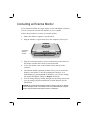
Connecting an External Monitor .............................................4-2
Connecting a USB Device .......................................................4-3
Connecting a Serial Device- ....................................................4-4
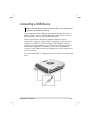
Connecting an IR Device.........................................................4-5
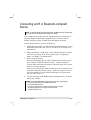
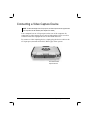
Connecting an IR or Bluetooth-compliant Device ..................4-7
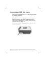
Connecting an IEEE 1394 Device ...........................................4-9
Connecting a Video Capture Device .....................................4-10
System Memory Upgrade ......................................................4-10
Chapter 5 Setup Configuration Utility (SCU).......................5-1
When and How to Use the SCU Program................................5-2
When to Use.......................................................................5-2
Starting SCU ......................................................................5-2
Moving Around and Making Selections ............................5-4
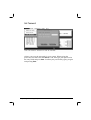
Startup Menu ...........................................................................5-5
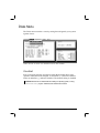
Disks Menu..............................................................................5-8
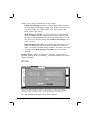
Components Menu...................................................................5-9
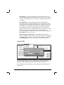
Power Menu...........................................................................5-13
Exit Menu ..............................................................................5-14
Chapter 6 Installing Software Drivers..................................6-1
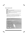
How to Use the CD..................................................................6-2
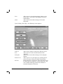
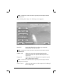
Installing Drivers for Windows 2000 ......................................6-3
Touchscreen Driver............................................................6-6
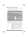
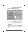
Installing Drivers for Windows XP .........................................6-7
Touchscreen Driver..........................................................6-10
Touchscreen Utility..........................................................6-16
Chapter 7 Caring for the Computer......................................7-1
Protecting the Computer ..........................................................7-2
Using the Password............................................................7-2
Using an Anti-Virus Strategy.............................................7-2
Taking Care of the Computer ..................................................7-3
General Guidelines.............................................................7-3
iii
Cleaning Guidelines ...........................................................7-4
Battery Pack Guidelines .....................................................7-4
When Traveling .......................................................................7-5
Chapter 8 Troubleshooting................................................... 8-1
Preliminary Checklist ..............................................................8-2
Solving Common Problems .....................................................8-3
Battery Problems................................................................8-4
CD / DVD/Combo Drive Problems....................................8-4
Display Problems ...............................................................8-5
Fingerprint Recognition Problems .....................................8-7
Hardware Device Problems................................................8-7
Hard Disk Drive Problems .................................................8-7
Infrared Problems...............................................................8-8
Keyboard, Mouse, and Touchpad Problems ......................8-8
LAN Problems ...................................................................8-9
WLAN Problems................................................................8-9
Modem Problems ...............................................................8-9
Power Management Problems (for Windows) .................8-11
Printer Problems...............................................................8-12
Software Problems ...........................................................8-12
Sound Problems ...............................................................8-13
Startup Problems ..............................................................8-14
Other Problems.................................................................8-15
Resetting the Computer .........................................................8-16
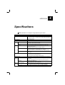
Appendix A Specifications ................................................... A-1
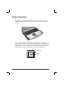
Appendix B Fingerprint Recognition System ..................... B-1
Finger Placement .................................................................... B-2
Using the Fingerprint Recongnition System Utility ............... B-3
iv
Preface
This manual contains information that will help you operate the
computer. It is divided into 8 chapters and an appendix.
Chapter 1, Getting Started, takes you through the process of setting
up the computer and identifying its external components.
Chapter 2, Operating Your Computer, tells you how to use the
computer’s components and features.
Chapter 3, Managing Power, provides information on power.
Chapter 4, Expanding Your Computer, provides information on
installing and using peripheral devices.
Chapter 5, SCU (Setup Configuration Utility), describes the SCU
program that configures the computer’s BIOS settings.
Chapter 6, Installing Software Drivers, describes how to install the
drivers and utilities supplied with the computer.
Chapter 7, Caring for the Computer, gives you tips in care and
maintenance.
Chapter 8, Troubleshooting, gives solutions to common problems
you may encounter when using the computer.
Appendix A, Specifications, gives a brief specification of the
computer.
v
Appendix B, Fingerprint Recognition System, provides
information on using the system’s fingerprint recognition system.
Notational Conventions
Throughout this manual, the following conventions are used to
distinguish elements of text.
NOTE: identifies additional information that requires special attention.
CAUTION: identifies important information which, if not followed, may result in loss of
data or damage to the computer.
Keyboard keys are shown in a bold typeset. For example:
Press Enter to complete.
When keys are joined by a plus sign (+), press the first key, and, while
keeping the first key down, press the remaining keys, finally release all
the keys. When necessary, keys are also shown in graphics.
A title, command, setup item, or button that you can see on the screen is
shown in boldface. A value or an option that you can select for a setup
item is shown in italic. For example:
Select Power Management, set it to Enabled, and then click the
OK button.
vi
CHAPTER
1
Getting Started
Congratulations on purchasing this computer.
This high performance notebook computer is especially designed for the
practical applications of warehouses, automobiles, vehicles, public
security, repairing, assisting the handicapped, and other demanding
situations where conventional notebook computers just cannot measure
up.
This chapter first tells you step by step how to get the computer up and
running. You will find instructions for these procedures:
Unpacking
Connecting to AC power
Opening the cover
Turning on the computer
Turning off the computer
Then, you will find a section briefly introducing the external components
of the computer. And the last section navigates you to the information
you may need after the computer is ready for use.
Getting the Computer Running
This section guides you through the procedures for getting the computer
ready for operation.
Unpacking
After unpacking the shipping carton, you should find these standard
items:
Notebook computer
Accessories:
− AC adapter (100~240 VAC, 50/60 Hz)
− AC power cord (US, CE, UK, SA)
− Driver CD
− Fingerprint recognition scanner in main system (includes
software)
− This Operation Manual
Inspect all the items. If any item is damaged or missing, notify your
dealer immediately.
Keep the shipping carton and packing materials in case you need to ship
or store the computer in the future.
Connecting to AC Power
The computer operates either on the external AC power or internal
battery power. It is suggested that you use AC power when you start up
the computer for the first time.
CAUTION: Use only the AC adapter included with your computer. Using other AC
adapters may damage the computer.
1-2
Getting Started
NOTE:
Power Supply Cord: (optional) Detachable, minimum 1.5 m long. Listed, rated
minimum 125 V, 7 A, having a 2/18 AWG, type SVT flexible cord. One end terminates
with a parallel blade, molded-on, attachments plug with a 7 A, 125 V (NEMA 1-15P)
configuration; other end terminates with a molded-on appliance coupler.
Alternative: (optional) Detachable, maximum 4.5 m (14.76 ft) long. Listed, rated
minimum 250 V, 6 A, having a 3/18 AWG, type SVT flexible cord. One end terminates
with a Tandem blade, grounding, listed molded-on, attachments plug with a 6 A, 250 V
(NEMA 6-15P) configuration; other end terminates with a molded-on appliance
coupler.
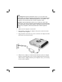
1. Make sure the computer is turned off.
2. Plug the DC cord of the AC adapter to the power connector on the
rear side of the computer.
3. Plug the female end of the AC power cord to the AC adapter and the
male end to an electrical outlet.
4. When the AC adapter is connected, the indicator on the AC adapter
lights up, indicating that power is being supplied from the electrical
outlet to the AC adapter and onto your computer. Now, you are ready
to turn on the computer.
Getting Started
1-3
CAUTION:
When you disconnect the AC adapter, disconnect from the electrical outlet first and
then from the computer. A reverse procedure may damage the AC adapter or the
computer.
When unplugging the connector, always hold the plug head. Never pull on the cord.
NOTE: When the AC adapter is connected, it also charges the battery pack. For
information on using battery power, see Chapter 3.
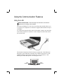
Opening the Cover
CAUTION: Be gentle when opening and closing the cover. Opening it vigorously or
slamming it shut could damage the computer.
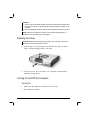
1. Open the top cover by pulling on the handle, inserting your index
finger, and then pulling on the cover latch.
2. Lift up the cover. You can tilt the cover forward or backward for
optimal viewing clarity.
Turning On and Off the Computer
Turning On
1. Make sure the computer is connected to AC power.
2. Press the power button.
1-4
Getting Started
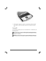
3. Each time the computer is turned on, it performs a Power-On Self
Test (POST), and the operating system such as Windows should
start.
Turning Off
To turn off the computer power, use the “Shut Down” command of your
operating system.
NOTE: There are other ways you can stop the computer so that you will be back to
where you left off when you next turn on the computer. (See “Stopping the Computer”
in Chapter 2 for information.)
CAUTION: If you have to turn the computer on again immediately after turning it off,
wait for at least five seconds. Turning the computer off and on rapidly can damage it.
Getting Started
1-5
Taking a Look at the Computer
This section identifies the external components of the computer and
briefly describes the function of each component.
NOTE: Depending on the model you purchased, the appearance of your computer may
not exactly be the same as those shown in this manual.
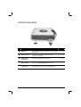
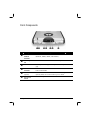
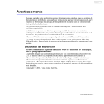
Right-Side Components
Ref
Component
Description
See Also
n
IEEE 1394 Port Connects a 1394 device, such as a scanner,
printer, digital camera, joystick, and more.
o
USB Ports
Each of the two ports connects a USB device,
such as a USB floppy drive, printer, digital
camera, joystick, and more.
P. 4-3
p
RJ-45 (LAN)
Link Indicator
Glows green when the system has an available
connection to LAN (Local Area Network).
P. 2-24
q
RJ-45
Connector
Connects the LAN cable.
P. 2-24
r
RJ-45 Active
Indicator
Blinks green when the system is accessing the
LAN.
P. 2-24
s
CD R-W/
DVD-Combo
Accepts a compact disc (CD) for installing or
loading software, accessing data, and playing
P. 2-17
1-6
P. 4-7
Getting Started
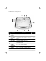
Left-Side Components
Ref
Component
Description
See Also
n
IR Port
Connects an IrDA-compliant device for wireless
data transfer.
P. 4-5
o
Bluetooth Port
Connects a bluetooth-capable device for
wireless data transfer.
P. 4-5
p
Microphone
Connector
Connects an external microphone.
q
Keyboard BIOS Use this to turn off the system when resetting the
system using Ctrl+Alt+Del does not work.
Reset Switch
P. 8-17
r
Audio Output
Connector
Connects a set of headphones, external speakers
with amplifier, or an audio recording device.
P. 2-23
Getting Started
P. 2-23
1-7
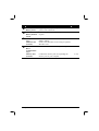
Rear Components
Ref
Component
Description
See Also
n
DVI-I Port
Connects an external monitor.
P. 4-2
o
Serial Port
Connects a serial device, such as an external
modem.
P. 4-4
p
Docking Port
For connecting to a Port Replicator / car mount.
q
Rear Cover
Latch
Locks the rear cover.
r
USB Ports
Each of the two ports connects a USB device,
such as a floppy disk drive, printer, digital
camera, joystick, and more.
P. 4-3
s
AV Input Port
Connects to a video recording device.
P. 4-8
t
Power
Connector
Connects the AC adapter.
P. 1-3
u
AC Power
Indicator
Glows green when the computer is using AC
power.
Blinks amber (orange) when the computer, using
AC power, is in Standby mode.
v
Battery Charge
Indicator
P. 1-4
Glows green when the battery is fully charged
and connected to AC power.
Glows amber (orange) when the battery is being
charged.
1-8
Getting Started
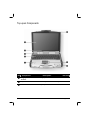
Front Components
Ref
Component
Description
See Also
n
Wireless
Modem
Antenna
Serves as the antenna for the wireless modem
(RDLAP, GPRS, iDEN, and CDMA).
P. 2-27
o
Stereo Speaker
Set
Sends out sound and voice from the computer.
P. 2-22
p
Handle
Allows you to carry your computer for an easy
grip.
q
Wireless LAN
Antenna
Serves as the antenna for the WLAN. It is
built-in the handle.
P. 2-25
r
GPS Antenna
(option)
Serves as the antenna for the Global Positioning
System (GPS). It is built-in the top cover latch.
P. 2-27
s
Top Cover
Latch
Locks the top cover.
Getting Started
P. 1-4
1-9
Bottom-Side Components
Ref
Component
n
X-bay Module
Antenna
Connector
Serves as the interface between the system and
antenna of the X-bay module.
o
CD Drive
Lock/Unlock
Switch
Allows you to lock the CD drive in place (can
also contain the floppy disk drive or secondary
battery).
P. 2-13,
2-17
p
CD/DVD Drive
Eject Latch
Allows you to remove the CD drive (can also
contain the CD R-W or DVD drive).
P. 2-13
q
GPS Connector Serves as the interface between the system and
external GPS antenna.
r
CPU Socket and Inside is the CPU of your computer and cooling
fan to protect it from overheating.
Sealed CPU
Cooling Fan
s
Ventilation
Openings
1-10
Description
See Also
Do not cover or block the ventilation openings
for air circulation thus preventing overheating.
Getting Started
Ref
Component
Description
See Also
t
Primary
Battery Pack
Supplies power to your computer when external
power is not connected.
P. 3-3
u
Secures the primary battery compartment cover
Primary
Battery Release in place.
Latch
P. 3-5
v
X-Bay Interface
(top)
Mini PCI Slot
(bottom)
Connects additional wireless modem (GPRS/
GSM or iDEN).
Inside is the Mini PCI slot for using an optional
Mini PCI card.
w
Hard Disk
Drive
Compartment
(top)
Memory Slot
(bottom)
Contains the hard disk drive of your computer.
Getting Started
Contains the memory slot for expanding the
memory size of your computer.
P. 2-15
P. 4-9
1-11
Top-open Components
Ref
Component
Description
See Also
n
Fingerprint
Scanner
Contains the fingerprint sensor.
P. B-1
o
p
Keyboard
Serves as the data input device of the computer.
P. 2-4
Power Button
Turns the computer power ON and OFF.
P. 1-5
1-12
Getting Started
q
Device
Indicators
Show the current status of the computer’s
devices.
Power on / Standby mode indicator
Hard disk drive in-use indicator
P. 1-3
P. 2-15
Num Lock indicator
P. 2-6
Caps Lock indicator
P. 2-4
Scroll Lock indicator
P. 2-4
r
LCD Screen
Displays the output of the computer.
P. 2-20
s
Light Sensor
Automatic light sensor for dimming the
display’s backlight.
P. 2-20
t
Touchpad
Serves as the pointing device of the computer.
u
Device
Indicators
Show the current status of the computer’s
devices.
CD/DVD drive in-use indicator
Getting Started
P. 2-9
P. 2-19
Battery power indicator –
Glows green when the computer is using battery
power.
Blinks green when the computer, using battery
power, is in Standby mode.
Blinks amber (orange) when the battery is
almost completely discharged.
P. 3-3
Battery charge indicator –
Glows green when the battery is fully charged
and connected to AC power.
Glows amber (orange) when the battery is being
charged.
P. 3-3
Glows green when the touchpad is enabled. Can
be enabled/disabled using the hot keys Fn+F7.
P. 2-9
AC in and HDD heater on indicator –
Glows green when the computer is connected to
AC power.
Blinks red when the hard disk heater is below
2° C, and can’t power on.
P. 1-4
P. 2-13
1-13
Where to Go from Here
As your computer is ready for operation, you may want to do any of the
following now:
For this purpose…
To know more about the computer…
Do this…
Go on to the next chapter.
To install the operating system if your See the operating system manual.
dealer has not already done so…
To know more about the operating
system…
Read the operating system manual.
To install the drivers if your dealer has See Chapter 6.
not already done so…
To set a power-on password…
See “Startup Menu” in Chapter 5.
To charge the battery pack for the first See “Charging the Battery Pack” in
time…
Chapter 3.
1-14
Getting Started
CHAPTER
2
Operating Your Computer
This chapter provides information about the use of the computer.
If you are new to computers, reading this chapter will help you learn the
operating basics. If you are already a computer user but are new to
notebook computers, you may choose to read only the parts containing
information unique to your computer.
Described in this chapter are the operating basics of these components:
Keyboard
Touchpad
Touchscreen
Floppy disk drive
Hard disk drive
CD/DVD drive
And these features:
Starting and stopping the computer
Video features
Audio features
Communication features
Starting and Stopping the Computer
There are a number of ways to start and stop the computer.
Starting the Computer
You always start the computer using the power button.
A computer starts up with an operating system (OS) existing on the
storage device such as the hard disk; or from a floppy disk or CD if you
have the respective modules installed. The computer will automatically
load the OS after you turn it on. This process is called booting.
NOTE: An operating system is the platform for all your software application programs to
run on. The most widely used operating system today is Microsoft Windows.
Stopping the Computer
When you finish a working session, you can stop the computer by turning
off the power or leaving the computer in Standby or Hibernation mode:
To stop in
this mode…
Off
Do this…
To start up or
resume again
Follow the shutdown procedure of your
operating system. This can prevent loss of
unsaved data or damage to your software
programs.
Press the power
button.
If the system is locked up because of
hardware or software problems, press the
power button to turn off the computer.
Standby
2-2
Depending on your settings in Windows,
you can place the computer in Standby
mode by:
• Closing the display cover
• Pressing the power button
Press any key.
Operating Your Computer
To stop in
this mode…
Do this…
Hibernation
Depending on your settings in Windows,
you can place the computer in
Hibernation mode by:
• Closing the display cover.
• Pressing the power button
To start up or
resume again
Press the power
button.
If you choose to stop in Standby or Hibernation mode, you can return to
where you left off the next time you start up the computer. (See “Power
Management” in Chapter 3 for more information.)
Operating Your Computer
2-3
Using the Keyboard
Your keyboard has all the standard functions of a full-sized computer
keyboard plus a Fn key added for specific functions.
The standard functions of the keyboard can be further divided into four
major categories:
Typewriter keys
Cursor-control keys
Numeric keys
Function keys
Typewriter Keys
Typewriter keys are similar to the keys on a typewriter. Several keys are
added such as the Ctrl, Alt, Esc, and lock keys for special purposes. When
the lock keys (Caps Lock, Num Lk, and Scroll Lk) are pressed, their
corresponding indicators light up.
The Control key is normally used in combination with other keys for
program-specific functions. The Alternate key is normally used in
combination with other keys for program-specific functions. The Escape
key is usually used for stopping a process. Examples are exiting a
program and canceling a command. The function depends on the program
you are using.
2-4
Operating Your Computer
Cursor-Control Keys
NOTE: The word “cursor” refers to the indicator on the screen that lets you know
exactly where on your screen anything you type will appear. It can take the form of a
vertical or horizontal line, a block, or one of many other shapes.
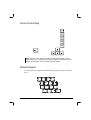
Numeric Keypad
A 15-key numeric keypad is embedded in the typewriter keys as shown
next:
Operating Your Computer
2-5
Numeric keys facilitate entering of numbers and calculations. When Num
Lock is on, the numeric keys are activated; meaning you can use these
keys to enter numerals.
NOTES:
When the numeric keypad is activated and you need to type the English letter in the
keypad area, you can turn Num Lock off or you can press Fn and then the letter
without turning Num Lock off.
Some software may not be able to use the numeric keypad on the computer. If so,
use the numeric keypad on an external keyboard instead.
Euro Symbol
You can press the Euro dollar sign
on the keyboard.
To press the Euro sign on the keyboard, hold down either of the Alt
keys and type 0128 on the numeric keypad of your keyboard.
To press the Euro sign on an UK keyboard, hold down the Alt Gr key
and press 4 (which has an Euro sign on it).
Windows Keys
The keyboard has two keys that perform Windows-specific functions:
Windows Logo key and
Application key.
Windows Logo key opens the Start menu and performs
The
software-specific functions when used in combination with other keys.
The
Application key usually has the same effect as a right mouse
click. (See your Windows manual for more information.)
Function Keys
On the top row of the keys are the function keys: F1 to F12. Function keys
are multi-purpose keys that perform functions defined by individual
programs.
2-6
Operating Your Computer
Fn Key
The Fn key, at the lower left corner of the keyboard, is used with another
key to perform the alternative function of a key. The letter “Fn” and the
alternative functions are identified by the color of blue on the keytop. To
perform a desired function, first press and hold Fn, then press the other
key.
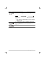
Hot Keys
Hot keys refer to a combination of keys that can be pressed any time to
activate special functions of the computer. Most hot keys operate in a
cyclic way. Each time a hot key combination is pressed, it shifts the
corresponding function to the other or next choice.
You can easily identify the hot keys with the icons imprinted on the
keytop. The hot keys are described next.
Key
Description
Toggles keyboard backlight on/off. (Brightness will be
controlled by ambient light sensor.)
Decreases the sound volume.
Increases the sound volume.
Decreases the LCD brightness.
Increases the LCD brightness.
Switches LCD on and off.
Operating Your Computer
2-7
Key
Description
Switches the display output to one of the following when an
external device is connected.
Upon booting the system with CRT:
LCD
CRT
LCD & CRT
NOTES:
If the display mode is set to 256 colors or lower, or in DOS
mode, there will be only two modes for selecting: CRT only
and LCD & CRT.
This function only applies to Plug & Play CRT monitors.
Serves as the sleep button that you can define with Windows’
Power Management. (See the “Power Management” in
Chapter 3.)
Switches GPS function on and off.
2-8
Operating Your Computer
Using the Touchpad
CAUTION: Do not use a sharp object such as a pen on the touchpad. Doing so may
damage the touchpad surface.
NOTES:
A touchpad indicator is found on the keyboard panel, use the Fn+F7 hot keys to
enable/disable this function.
For optimal performance of the touchpad, keep your fingers and the pads clean and
dry. When tapping on the pad, tap lightly. Do not use excessive force.
The touchpad is a pointing device that allows you to communicate with
the computer by controlling the location of the pointer on the screen and
making selection with the buttons.
The touchpad consists of a rectangular pad and four buttons. To use the
touchpad, place your forefinger or thumb on the pad. The rectangular pad
acts like a miniature duplicate of your display. As you slide your fingertip
across the pad, the pointer (also called cursor) on the screen moves
accordingly. When your finger reaches the edge of the pad, simply
relocate yourself by lifting the finger and placing it on the other side of
the pad.
Here are some common terms that you should know when using the
touchpad:
Operating Your Computer
2-9
Term
Action
Point
Move your finger on the pad until the cursor points to the
selection on the screen.
Click
Press and release the left button.
–or–
Tap gently anywhere on the pad.
Doubleclick
Press and release the left button twice in quick succession.
–or–
Tap twice on the pad rapidly.
Drag
and
drop
Press and hold the left button, then move your finger until you
reach your destination (drag). Finally, release the button (drop)
when you finish dragging your selection to the destination. The
object will drop into the new location.
–or–
Gently tap twice on the pad and on the second tap, keep your
finger in contact with the pad. Then, move your finger across the
pad to drag the selected object to your destination. When you lift
your finger from the pad, the selected object will drop into place.
Scroll
To scroll is to move up and down or left and right in the working
area on the screen.
To move vertically, place your finger on the right edge of the
pad and slide your finger up and down along the edge To move
horizontally, place your finger on the bottom edge of the pad and
slide your finger left and right.
This function works only after you install the touchpad driver
supplied with the computer and it may not work for all
applications.
TABLE NOTE: If you swap the left and right buttons, “tapping” on the touchpad
as an alternative method of pressing the left button will no longer be valid.
2-10
Operating Your Computer
Configuring the Touchpad
You may want to configure the touchpad to suit your needs. For example,
if you are a left-handed user, you can swap the two buttons so that you
can use the right button as the left button and vise versa. You can also
change the size of the on-screen pointer, the speed of the pointer, and so
on.
To configure the touchpad, you can use the standard Microsoft or IBM
PS/2 driver if you are using Windows. However, you can install the
touchpad driver supplied with your computer to take advantage of more
powerful features. (For information on installing the driver, see “How to
Use the Driver CD” in Chapter 6.)
Operating Your Computer
2-11
Using the Touchscreen (option)
CAUTION: Do not use a sharp object such as a ballpoint pen or pencil on the
touchscreen. Doing so may damage the touchscreen surface.
The touchscreen is a touch-sensitive device that allows you to
communicate with the computer by controlling the location of the pointer
on the screen and making selection with the buttons.
The touchscreen needs a special device driver support that allows you to
easily use the computer without any external pointing device. (For
information on installing the driver, see Chapter 6.)
Here are some common terms that you should know when using the
touchscreen:
Term
Action
Point
Move your finger on the touchscreen until the cursor
points to the selection on the screen.
Click
Tap gently anywhere on the touchscreen.
Double-click
Tap twice on the touchscreen rapidly.
Drag and
drop
Press lightly on the touchscreen and move your finger until
you reach your destination (drag). Finally, release your
finger (drop) when you finish dragging your selection to
the destination. The object will drop into the new location.
Scroll
To scroll is to move up and down or left and right in the
working area on the screen.
To move vertically, place your finger on the right edge of
the touchscreen and slide your finger up and down along
the edge. To move horizontally, place your finger on the
bottom edge of the touchscreen and slide your finger left
and right.
This function works only after you install the touchscreen
driver supplied with the computer and it may not work for
all applications.
2-12
Operating Your Computer
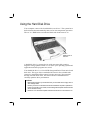
Using the Hard Disk Drive
Your computer comes with a hard disk drive as drive C. The system has a
built-in heater that automatically turns on for low temperature operation.
The AC in / HDD heater on indicator blinks red when heater is on.
AC in /
HDD heater on
indicator
A hard disk drive is a storage device with non-removable, rotating,
magnetic storage platters inside it. It is where your operating system and
application software programs are stored.
Your hard disk drive is a 2.5-inch IDE (Integrated Drive Electronics) hard
disk drive. This type of drive embodies the latest in fast, reliable mass
storage by integrating all the control circuitry necessary for operation
directly onto the drive itself. This allows the drive manufacturer to
carefully optimize drive performance.
CAUTION:
Make regular backups of your data files from your hard disk drive to floppy disks or
other storage media.
Never try to remove or install the hard disk drive while the computer is powered on.
Doing so can result in loss of data, and can damage the computer and the hard disk
drive’s sensitive circuitry.
Never turn off or reset the computer while the hard disk drive in-use indicator is on.
Operating Your Computer
2-13
Using the CD/DVD Drive (option)
Depending on the model, your computer comes with a CD R-W or
DVD-Combo drive. This drive is usually configured as drive D and is
connected through the CD drive bay located on the right side of the
computer.
The drive uses removable 5.25-inch silver discs, which look like standard
music CDs. It is an ideal medium to use for distributing multimedia
because of the huge amount of data that a disc can store.
Depending on the model, your drive is one of the following:
CD R-W drive not only read CDs, audio CDs, CD-R, and CD-RW
discs but also write to CD-R and CD R-W discs.
DVD-Combo drive can work both as a DVD drive and CD R-W
drive.
NOTE: If the CD R-W / DVD-Combo drive would be operating for more than half an
hour (such as showing a DVD title), use the AC power source instead of the battery. If
not, the battery may run out of power before the operation is complete.
CAUTION:
1. When inserting a CD, do not use force.
2. Make sure the CD is correctly inserted into the tray, and then close the tray.
3. Do not leave the CD tray open. Also, avoid touching the lens in the tray with your
hand. If the lens becomes dirty, the CD may malfunction.
4. Do not wipe the lens using materials with rough surface (such as paper towel).
Instead, use a cotton swab to gently wipe the lens.
FDA regulations require the following statement for all laser-based devices:
“Caution, Use of controls or adjustments or performance of procedures other than
those specified herein may result in hazardous radiation exposure.”
NOTE: The CD R-W / DVD-Combo drive is classified as a Class 1 laser product. This
label is located on the CD R-W / DVD-Combo drive.
2-14
Operating Your Computer
NOTE: For DVD-Combo drive only.
This product incorporates copyright protection technology that is protected by method
claims of certain U.S. patents and other intellectual property rights owned by
Macrovision Corporation and other rights owners. Use of this copyright protection
technology must be authorized by Macrovision Corporation, and is intended for home
and other limited viewing uses only unless otherwise authorized by Macrovision
Corporation. Reverse engineering or disassembly is prohibited.
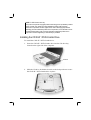
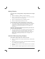
Installing the CD R-W / DVD-Combo Drive
To install the CD R-W / DVD-Combo drive:
1. Insert the CD R-W / DVD-Combo drive into the CD drive bay
located on the right side of the computer.
CD drive
2. Slide the CD drive lock/unlock switch to the lock position to secure
the CD R-W / DVD-Combo drive in place.
Operating Your Computer
2-15
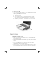
Inserting and Removing a CD
NOTE: The following procedure applies to inserting or removing a DVD disc as well.
Follow this procedure to insert or remove a CD.
1. Turn on the computer.
2. Press the eject button and the CD tray will slide out partially. Gently
pull on it until it is fully extended.
3. To insert a CD, place down the CD in the tray with its label facing up.
Slightly press the center of the CD until it clicks into place.
Eject button In-use
indicator
To remove a CD, hold the CD by its outer edge and lift it up from the
tray.
4.
Gently push the tray back into the drive.
NOTE: In the unlikely event that you are unable to release the CD tray by pressing the
eject button, you can manually release the CD. (See “CD R-W / DVD-Combo Drive
Problems” in Chapter 8.)
2-16
Operating Your Computer
Using the Video Features
The video subsystem of your computer features:
12.1/13.3-inch TFT (Thin-Film Transistor) color LCD display with
1024x768 XGA (Extended Video Graphics Array) resolution.
64 MB integrated video memory.
Simultaneous display on LCD and external monitor, which is useful
when you have a presentation as you can control the screen from your
computer and face the audience at the same time.
Dual view capability, which allows you to expand your desktop on
the screen to another display device so that you have more desktop
space to work on.
Power Management.
Touchscreen function (option).
Sunlight readable transflective LCD display (option).
NOTES:
Before using the dual view capability, the video driver supplied with your computer
must be installed.
The computer enters Standby or Hibernation mode when the LCD is closed. If you
want to use the computer with the LCD closed, set None to the “When I close the lid
of my portable computer” option in the Power Management Properties. Thus the
computer does not enter Standby or Hibernation mode when the LCD is closed.
Configuring the Display Modes
NOTES:
To take advantage of the enhanced video capabilities, the video driver supplied
with your computer must be installed.
When using CRT only, the resolution would depend on the supported resolution by
the CRT.
Operating Your Computer
2-17
Your computer has been set to a default resolution and number of colors
before shipment. You can view and change display settings through your
operating system. See your operating system documentation or online
help for specific information.
For displaying in higher resolutions, you can connect an external CRT
monitor that supports higher resolutions. (See “Connecting an External
Monitor” in Chapter 4 for more information.)
The following table lists the display modes supported by your computer.
Display Mode
Resolution
800x600
1024x768
LCD Only CRT Only Simultaneous Display
Colors
16-bit
√
√
√
32-bit
√
√
√
16-bit
√
√
√
32-bit
√
√
√
TABLE NOTES:
16-bit = High Color or 65,536 (64 K) colors; 32-bit = True Color 16,770,000 (16 M)
colors.
When using CRT only, the resolution would depend on the supported resolution by
the CRT.
2-18
Operating Your Computer
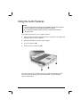
Using the Audio Features
NOTES:
To take advantage of the enhanced audio capabilities, the audio driver supplied
with your computer must be installed (see chapter 6 for details).
If you experience interference while recording, try lowering the microphone
recording volume.
The audio subsystem of your computer features:
Digital audio and analog mixing functions required for recording and
playing sound on your computer
Microsoft Windows Sound System support
A set of speakers ( )
External audio connectors ( )
Ways of playing and recording sound vary with the operating system
used. See your operating system documentation or online help for
specific information.
Operating Your Computer
2-19
Connecting Audio Devices
For higher audio quality, you can send or receive sound through external
audio devices.
Microphone Connector (
) can be connected to an external
microphone for recording voice or sound.
Audio Output Connector (
) can be connected to the line-in
connector of powered speakers with built-in amplifiers, headphones,
or earphone set. This connector is compliant with S/P-DIF
(Sony/Philips-Digital InterFace). You can connect audio equipment
with S/P-DIF to the computer. S/P-DIF is a new audio transfer file
format that ensures a high quality digital audio output through optical
fibers.
NOTE: When using external speakers/headphones or microphone, you cannot use the
internal one.
2-20
Operating Your Computer
Using the Communication Features
Using the LAN
NOTE for Windows 2000: To take advantage of the LAN feature, the LAN driver
supplied with your computer must be installed.
The internal 100Base-T LAN (Local Area Network) module allows you
to connect your computer to a network. It supports data transfer rate up to
100 Mbps.
To connect the network cable to the LAN module, connect one end of the
LAN cable to the RJ-45 connector on the computer and the other end to
the network hub.
The bottom left portion of the RJ-45 port contains the “Link Indicator,”
that glows green when the system has an available connection to LAN.
While the bottom right portion contains the “Active Indicator,” that
blinks green when the system is accessing the LAN.
Link
indicator
Operating Your Computer
Active
indicator
2-21
Using the Wireless LAN
Depending on your model, an internal Mini PCI wireless LAN (WLAN)
card may have been pre-installed by your computer manufacturer at the
factory. This card allows you to access corporate networks or the Internet
in a wireless environment.
The WLAN features include:
IEEE 802.11b standard compliance
2.4 GHz DSSS (Direct Sequence Spread Spectrum) technology
Peer-to-Peer (Ad-Hoc) and Access Point (Infrastructure) modes
support
WEP (Wired Equivalent Privacy) 64/128-bit data encryption
Transmission rate at 11 Mbps, 5.5 Mbps, 2 Mbps, and 1 Mbps with
automatic data rating
To take advantage of the WLAN feature, make sure that the WLAN
driver is installed correctly. (See Chapter 6 for more information.) If your
WLAN card was provided by your dealer instead of the computer
manufacturer, contact your dealer for the correct driver to use.
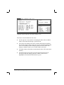
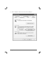
Configuring the WLAN
After driver installation, you can use the WLAN utility to configure and
monitor your WLAN connection. If you are using Windows XP, you can
also use its built-in WLAN utility. Follow this procedure to launch the
WLAN utility in Windows XP:
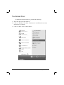
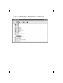
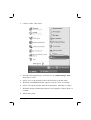
1. Select Control Panel from the Start menu.
2. Click Network and Internet Connections.
3. Click Network Connections, then double-click the Wireless
Network Connection icon
.
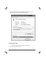
4. Click Properties in the Wireless Network Connection Status
dialog box.
5. You can configure your WLAN settings in the Wireless Network
Connection Properties dialog box.
2-22
Operating Your Computer
Turning Off/On the WLAN
NOTE: The FAA (Federal Aviation Agency) has deemed it unsafe to operate wireless
devices in aircraft as this may interfere with flight safety. Remember to select turn off
wireless LAN when using your computer in the airplane.
Upon booting-up your computer, the WLAN function is on.
To turn off the WLAN function, turn off the WLAN utility.
It takes approximately 30 seconds for your computer to make a successful
WLAN connection and approximately 10 seconds to disconnect.
Connecting to the Internet or a Network through
Wireless Data Services
Depending on your model, your computer includes an integrated GSM
(Global System for Mobile Communications) / GPRS (General Packet
Radio Service) feature.
After you establish a subscription with a GSM/GPRS service provider,
you can use the wireless data features of your computer. Check with your
service provider for a list of available wireless data services. Your service
provider may charge additional fees for use of data services.
There are two methods for wirelessly connecting to an ISP or network:
GSM data transmission (circuit-switched data)
GSM data services enable you to use the GSM component of your
computer as a built-in modem. You can use the service to connect to
the Internet through an ISP or dial in to a corporate network to browse
the Web or send and receive e-mail messages.
GPRS data transmission
GPRS is a high-speed data-on service that enables you to transmit
data over a mobile network. Subscribing to a GPRS service allows
you to transfer files, browse the Web and receive streaming audio and
video on your computer.
Connecting Using the GSM Modem
NOTE: To take advantage of the wireless modem feature, the PCI-952 driver supplied
with your computer must be installed (see chapter 6).
Operating Your Computer
2-23
Your computer can send and receive data via a mobile network using the
GSM protocol.
To send or receive data over a GSM network, you must have an account
with a service provider that supports GSM data services, and the service
provider must enable the data features on your account.
Configuring a GSM Modem Connection
Before you can use the GSM modem connection, make sure that you have
a subscription to the Circuit-Switched Data (CSD) network with your
service provider and you have an account with your service provider or
corporate network you are connecting to.
To connect to an ISP or dial in to a specific computer, you must configure
a connection for that service on your computer.
Connecting Using GPRS
Your computer can receive General Packet Radio Services (GPRS), a
high-speed data-only service that transmits data over a mobile telephone
network. In addition, GPRS provides permanent on-line connection.
To use GPRS, you must have a subscription to the function with a service
provider that supports GPRS.
Configuring a GPRS Connection
To connect to a GPRS network, you must configure a connection for that
service on your computer.
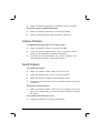
Connecting Using GPS
NOTE: To take advantage of the GPS feature, the PCI-952 driver supplied with your
computer must be installed (see chapter 6).
Navigation and positioning are crucial to so many activities and yet the
process has always been quite cumbersome. To try to figure out where
you are and where you are going, you need GPS technology.
The Global Positioning System (GPS) is a worldwide radio-navigation
system formed from a constellation of 24 satellites and their ground
stations. GPS uses these "man-made stars" as reference points to calculate
2-24
Operating Your Computer
positions accurate to a matter of meters. In fact, with advanced forms of
GPS you can make measurements to better than a centimeter! In a sense it
is like giving every square meter on the planet a unique address.
Here's how GPS works in five logical steps:
The basis of GPS is "triangulation" from satellites.
To "triangulate," a GPS receiver measures distance using the travel
time of radio signals.
To measure travel time, GPS needs very accurate timing that it
achieves with some tricks.
Along with distance, you need to know exactly where the satellites
are in space. High orbits and careful monitoring are the secret.
Finally you must correct for any delays the signal experiences as it
travels through the atmosphere.
Five broad categories of GPS application:
Location – determining a basic position
Navigation – getting from one location to another
Tracking – monitoring the movement of people and things
Mapping – creating maps of the world
Timing – bringing precise timing to the world
Operating Your Computer
2-25
2-26
Operating Your Computer
CHAPTER
3
Managing Power
Your computer operates either on external AC power or internal battery
power.
This chapter tells you how you can effectively manage power. To
maintain optimal battery performance, it is important that you use the
battery in the proper way.
The topics in this chapter include:
What is an AC adapter
How to charge the battery pack
When and how to initialize the battery pack
How to check the battery level
How to replace the battery pack
What happens when the battery is low and what actions to take
What is Power Management
How to save power
AC Adapter
CAUTION:
The AC adapter is designed for use with your computer only. Connecting the AC
adapter to another device can damage the adapter.
The AC power cord supplied with your computer is for use in the country where you
purchased your computer. If you plan to go overseas with the computer, consult
your dealer for the appropriate power cord.
When you disconnect the AC adapter, disconnect from the electrical outlet first and
then from the computer. A reverse procedure may damage the AC adapter or
computer.
When unplugging the connector, always hold the plug head. Never pull on the cord.
The AC adapter serves as a converter from AC (Alternating Current) to
DC (Direct Current) power because your computer runs on DC power,
but an electrical outlet usually provides AC power. It also charges the
battery pack when connected to AC power.
The AC adapter operates on any voltage in the range of 100 ~ 240 V AC.
3-2
Managing Power
Battery Pack
The battery pack is the internal power source for the computer. It is
rechargeable using the AC adapter.
The operating time of a fully charged battery pack depends on how you
are using the computer. When your applications often access peripherals,
you will experience a shorter operating time.
NOTE: Care and maintenance information for the battery is provided in the “Battery
Pack Guidelines” section in Chapter 7.
Charging the Battery Pack
NOTES:
Charging will not start if the battery’s temperature is below 0 °C (32 °F) or above 50
°C (122 °F).
The charging process will stop and the Battery Charge Indicator flashes amber
when the battery’s temperature gets above 60 °C (140 °F). If this happens, the
battery pack may be damaged. Please contact your dealer.
During charging, do not disconnect the AC adapter before the battery has been fully
charged; otherwise you will get a prematurely charged battery.
To charge the battery pack, connect the AC adapter to the computer and
an electrical outlet. The Battery Charge Indicator (
) on the computer
glows amber to indicate that charging is in progress. You are advised to
keep the computer power off while the battery is being charged. When the
battery is fully charged, the Battery Charge Indicator glows green.
It takes approximately 197 minutes to charge the battery pack to 80%
capacity and four or more hours to fully charge the battery pack when the
computer is off.
CAUTION: After the computer has been fully recharged, do not immediately disconnect
and reconnect the AC adapter to charge it again. Doing so may damage the battery.
NOTE: The battery level may automatically lessen due to the self-discharge process
(0.21% per day), even when the battery pack is fully charged (100%). This happens no
matter if the battery pack is installed in the computer.
Managing Power
3-3
Initializing the Battery Pack
You need to initialize a new battery pack before using it for the first time
or when the actual operating time of a battery pack is much less than
expected.
Initializing is the process of fully charging, discharging, and then
charging. It can take several hours.
1. Make sure the computer power is turned off. Connect the AC adapter
to fully charge the battery pack.
2. After the battery pack is fully charged, turn on the computer.
3. Disconnect the AC adapter and leave the computer on until the
battery is fully discharged. The computer will shut down
automatically.
4. Connect the AC adapter to fully charge the battery pack.
Checking the Battery Level
When the battery charge on the battery falls below 5%, then system will
shutdown.
NOTE: Any battery level indication is an estimated result. The actual operating time can
be different from the estimated time, depending on how you are using the computer.
You can check the approximate battery level using the battery meter
function of the operating system. To read the battery level in Windows,
click the
icon on the taskbar. (Click the
icon if the computer is
using AC power.)
3-4
Managing Power
Replacing the Battery Pack
CAUTION:
There is danger of explosion if the battery is incorrectly replaced. Replace the
battery only with the computer manufacturer’s optional battery packs. Discard used
batteries according to the dealer’s instructions.
Do not attempt to disassemble the battery pack.
If you often rely on battery power for a long period of time while
traveling, you may consider the purchase of an additional battery pack
from your dealer and keep it with you in a fully charged state as a backup.
To replace the battery pack, follow these steps:
1. Make sure the computer is not turned on or connected to AC power.
2. Slide the battery security lock outward to the unlock ( ) position
( ) and lift the battery pack compartment cover to take it off the
computer ( ).
3. Pull on the ribbon and take the battery pack off the computer.
4. Insert the new battery pack into the compartment.
Managing Power
3-5
Battery Low Signals and Actions
Battery Low occurs when the battery has approximately 10% (Windows
default setting) of its charge remaining. The computer gives warning
beeps or messages and the Battery Charge Indicator (
) blinks red to
alert you to take actions.
NOTE: You can set up your threshold and signals of Battery Low under Windows.
Immediately save your data upon Battery Low. The remaining operating
time depends on how you are using the computer. If you are using the
audio subsystem, hard or floppy disk drives, the battery might run out of
charge very quickly.
Always respond to Battery Low by placing your computer on Standby or
Hibernation mode, turning off the computer, or connecting the AC or car
adapter.
If you do not take any action and after a couple of warning beeps, the
computer will automatically hibernate and turn off.
CAUTION: If you fail to save your data when the battery completely runs out of charge,
then you lose your data.
3-6
Managing Power
Power Management
Your computer supports ACPI (Advanced Configuration and Power
Interface) for power management. The power management feature allows
you to reduce the power consumption for energy saving.
With an ACPI-compliant operating system such as Windows 2000 and
Windows XP, power supply to different computer components is
controlled on an as-needed basis. This allows maximum power
conservation and performance at the same time.
In general, Windows’ power management works in this way:
What…
When…
Power to the hard disk is turned off
When the hard disk has been idle for a
set period.
Power to the display is turned off
When the display has been idle for a set
period.
The computer enters Standby mode. When the entire system has been idle
The hard disk and display are turned for a set period.
off and the entire system consumes
When you press Fn+F10. *
less power.
When you close the cover. *
When you press the power button. *
The computer enters Hibernation
mode. (See the next subsection for
more information.)
When you press the power button. *
When you press Fn+F10. *
When you close the cover. *
* depends on your settings in Windows.
For detailed information on power management, see Windows’ Help.
Hibernation
Hibernation is a very useful feature. People frequently open many
applications when they use computers. It takes some time to get all these
applications open and running, and normally they all have to be closed
before the system can be turned off.
Managing Power
3-7
When you use the hibernation feature, you do not have to close the
applications. The computer stores the state of your computer to a file on
the hard disk and then shut down. The next time you turn on your
computer, you return to exactly where you left off.
3-8
Managing Power
Power-Saving Tips
In addition to your computer’s automatic power management, you can do
your part to maximize the battery’s operating time by following these
suggestions.
Do not disable Power Management.
Decrease the LCD brightness to the lowest comfortable level.
Disable the parallel and serial ports if no devices are connected to
these ports. (See “Components Menu” in Chapter 5.)
If you work with an application that uses the serial port, exit the
application when you finish using it.
Turn off the computer when you are not using it.
Managing Power
3-9
3-10
Managing Power
CHAPTER
4
Expanding Your Computer
You can expand the capabilities of your computer by connecting other
peripheral devices. When using a device, be sure to read the instructions
accompanying the device together with the relevant section in this
chapter.
This chapter gives guidelines on installing and using these devices:
External monitor
USB device
Serial device
IR and Bluetooth-capable devices
IEEE 1394 device
Video capture device
Connecting an External Monitor
If you want the benefits of a larger display screen with higher resolution,
you can connect an external CRT monitor to your computer.
Follow this procedure to connect an external monitor:
1. Make sure that the computer is not turned on.
2. Plug the monitor’s signal connector to the computer’s DVI-I port.
Connect to
external
monitor
3. Plug one end of the monitor’s power cord into the power socket on
the monitor and the other end to an electrical outlet.
4. To use the monitor, turn on the monitor before turning on the
computer.
5. The monitor should respond by default. If not, you can switch the
display to the monitor or to both (simultaneous display), or to
multi-display by pressing Fn+F9. In Windows, you can also change
the display through the settings in Display Properties.
6. You can change display settings through your operating system. See
your operating system documentation or online help for specific
information.
CAUTION: Do not disconnect the external monitor while the computer is in Standby
mode or Hibernation mode. If no external monitor is connected when the computer
resumes, the LCD remains blank and the output is not displayed.
4-2
Expanding Your Computer
Connecting a USB Device
NOTE: To take advantage of the USB 2.0 feature, the USB 2.0 driver supplied with your
computer must be installed (see chapter 6).
Your computer has four USB ports that supports transfer rates up to 12
MB/s for USB 1.1 devices and 480 MB/s for USB 2.0 devices, such as
digital camera, scanner, printer, modem, and mouse.
USB is specified to be an industry standard extension to the PC
architecture. It supports “Plug-and-Play” technology so you can install
and remove USB devices without turning off the computer. With its
multiple connection capability, up to 127 devices can be connected in a
daisy-chain configuration. In addition, you can use a USB hub that
converts a single USB connector into multiple ports where USB devices
can be connected.
To connect a USB device, simply plug the device cable to one of the USB
ports.
Expanding Your Computer
4-3
Connecting a Serial Device
Your computer has a serial port for connecting a serial device such as an
external modem.
Follow this procedure to connect a serial device:
1. Make sure the “COM1 Ports” item is set properly in the SCU
program. (See “Components Menu” in Chapter 5 for information.)
2. Make sure the computer is not turned on.
3. Plug the device cable to the serial port on the rear of the computer.
4. Turn on the computer.
NOTE: Portable modems that derive power through the serial port cannot be used with
the computer. Instead, use a modem that is powered by its own internal battery or
external AC power.
4-4
Expanding Your Computer
Connecting an IR or Bluetooth-compliant
Device
NOTE: To take advantage of the Bluetooth feature, the Bluetooth driver supplied with
your computer must be installed (see chapter 6 for details).
Your computer has an IR (infrared) / Bluetooth port for connecting an
infrared-equipped / Bluetooth-compliant device wirelessly such as
another computer, printer, or PDA (Personal Digital Assistant).
Follow this procedure to connect an IR device:
1. Under Windows, make sure that the IrDA Fast Infrared Port is set to
HP HSDL-2300/3600. (See “How to Use the CD” in Chapter 6 for
information.)
2. Make sure that the “COM Ports” and its “Mode Setting For COM2”
items are set properly in the SCU program. (See “Components
Menu” in Chapter 5 for information.)
3. When using the IR port:
Place the transmitting device where its IR port faces the IR port of
your computer within the effective range − within ±20-degrees
vertical angle and within ±20-degrees horizontal angle at no greater
than 0.8~1.0 meter distance.
Place the receiving device where the IR port of your computer faces
its IR port within the effective range − within ±15-degrees vertical
angle and within ±15-degrees horizontal angle at no greater than
0.8~1.0 meter distance.
4. To take advantage of the IR/Bluetooth communications, you need a
third party software.
NOTES: During infrared/Bluetooth communication, take note of the following:
Do not move the computer and IR/Bluetooth device.
Do not enter Standby mode.
Do not use a cell phone or another IR device near the computer.
Avoid strong light such as sunlight or fluorescent light.
Disable the screen saver.
Expanding Your Computer
4-5
4-6
Expanding Your Computer
Connecting an IEEE 1394 Device
Your computer has an IEEE 1394 port on the right side of the computer
for connecting 1394 devices.
IEEE 1394 is the next-generation serial bus standard, featuring
high-speed data transfer, multi-channel communication link, and “Hot
Plug” connectivity. It allows connection of up to 63 devices. The
applications include not only computer peripheral devices such as
scanner, printer and high-quality CCD, but also consumer electronic
equipment such as DVCAM and VCR.
To connect an 1394 device, simply plug the device cable to the IEEE
1394 port of the system.
Expanding Your Computer
4-7
Connecting a Video Capture Device
NOTE: To take advantage of the AV input port, the Video Capture driver supplied with
your computer must be installed (see chapter 6 for details).
Your computer has an AV input port on the rear of the computer for
connecting a video capture device such as high-quality CCD, as well as
consumer electronic equipment such as DVCAM and VCR.
To connect a video capturing device, simply plug the device cable to the
AV input port (conexant 878A PCI; BNC-type) of the system.
Connect to video
capture device
4-8
Expanding Your Computer
System Memory Upgrade
You can upgrade your computer by changing system memory to a
maximum of 1 GB on the two 200-pin PC2100 DDR SO-DIMM slots.
However, to avoid damage during the installation procedure, please ask
your dealer for help.
Expanding Your Computer
4-9
4-10
Expanding Your Computer
CHAPTER
5
Setup Configuration Utility (SCU)
SCU is a program for configuring the BIOS (Basic Input/Output System)
settings of the computer.
BIOS is a layer of software, called firmware, that translates instructions
from other layers of software into instructions that the computer hardware
can understand. The BIOS settings are needed by your computer to
identify the types of installed devices and establish special features.
This chapter tells you how to use the SCU program.
When and How to Use the SCU Program
When to Use
You need to run the SCU program when:
You see an error message on the screen requesting you to run Setup.
You want to restore the factory default settings.
You want to modify some specific settings according to the
hardware.
You want to modify some specific settings to optimize system
performance.
Starting SCU
NOTES:
The Setup screens shown in this chapter are for your reference only. The actual
items or settings on your computer may differ.
The Setup program may have been updated after the publication of this manual.
The settings you select in your operating system might override similar settings in
Setup.
To run SCU, press F2 when the prompt appears in the lower left corner of
the screen during system startup. The prompt shows up on the screen for
only a few seconds. You must press F2 quickly. The SCU menu appears
as shown next.
5-2
Setup Configuration Utility (SCU)
The menu can be divided into four areas:
On the top line is the menu bar containing the titles of the available
menus. Each menu title brings a specific menu.
The center left column of the menu contains information regarding
the current settings of the system. If you open a pull-down menu and
select an item that provides multiple options, the left column will
display a submenu where you can make further selections.
The right column of the menu contains details of the CPU and system
memory.
The bottom lines of the menu provide keyboard instructions for
moving around and making selections. When a menu item is
highlighted, more detailed information is given.
Setup Configuration Utility (SCU)
5-3
Moving Around and Making Selections
A brief description of keyboard usage is listed next:
Key
Function
←, →
Selects a menu title.
↑, ↓
1) Selects an item or option.
2) Brings up/down the value.
Enter
1) Brings up the sub-menu when available.
2) Opens or closes the options window when an item is selected.
Tab
Jumps from one item to another.
Esc
1) Exits the SCU program.
2) Returns to the previous menu if in a sub-menu.
3) Closes the options window if one is open.
NOTE: You are advised to use the mouse (if installed) as it is more straightforward than
using the keyboard.
5-4
Setup Configuration Utility (SCU)
Startup Menu
The Startup menu contains the basic configuration setting of the system,
the sequence of the devices to be searched for the operating system, and a
security setting that safeguards your system against unauthorized use.
Date and Time
Setup Configuration Utility (SCU)
5-5
Sets the system time (Hour, Minute, Second) and date (Month, Day,
Year).
Boot Device
Sets the first, second, third, and fourth booting device. The system will
try to boot from the first device but if it is not available, will try the next
boot device. If you set the first boot device to PXE LAN, the system will
boot from the LAN server first. The options are Hard Disk C, CD-ROM
Drive, Diskette A, and PXE LAN. The default setting is Diskette A, Hard
Disk C, CD-ROM Drive, then PXE LAN.
NOTE: If you set all booting options to the same device, then the computer will try to
boot from that device only.
5-6
Setup Configuration Utility (SCU)
Set Password
Allows you to set the password for your system. When typing the
password, first make sure that Num Lk is off, then type your password in
the entry fields and press Enter. Confirm your password by typing it again
and pressing Enter.
Setup Configuration Utility (SCU)
5-7
Disks Menu
The Disks menu contains a security setting that safeguards your system
against viruses.
Virus Alert
Sets if a warning message will appear when the hard disk boot sector
(partition table) has been changed. A checkmark ( ) indicates enabled,
while an underline (_) indicates disabled. The default setting is disabled.
CAUTION: Set this item to disabled before installing an operating system, running
Fdisk or Format program. Otherwise, the intended action will fail.
5-8
Setup Configuration Utility (SCU)
Components Menu
The Components menu contains a security setting that safeguards your
system against viruses.
COM Ports
Setup Configuration Utility (SCU)
5-9
Allows you to configure the IR port of the computer.
COM1/2/3/4 Settings sets the I/O (Input/Output) address and the
Interrupt ReQuest line (IRQ) settings of the IR port. The options are
Disabled; COM1, 3F8, IRQ4; COM2, 2F8, IRQ3; COM3, 3E8,
IRQ6; COM4, 2E8, IRQ11.
Mode Setting for COM2 sets the communication compatibility
mode according to the type of the IR device to be connected. The
options are IrDA (HPSIR) and Fast IR. The default setting is Fast IR.
This item is not valid for setting if the COM1/2/3/4 Settings item is
set to Disabled.
DMA Setting For Fast IR sets the DMA (Direct Memory Access)
channel of the IR port in Fast IR mode. The options are DMA 0,
DMA 1, and DMA 3. Default setting is DMA 0. This item is not valid
for setting if the Mode Setting for COM2 item is set to IrDA
(HPSIR).
Pointing Device enables or disables the touchpad. A checkmark ( )
indicates enabled, while an underline (_) indicates disabled. The default
setting is disabled.
LPT Port
This item configures the parallel port of the computer.
5-10
Setup Configuration Utility (SCU)
Port Address sets the I/O address and the interrupt request line
settings of the parallel port. The options are None; LPT1, 378, IRQ
7; LPT2, 278, IRQ 5;and LPT3, 3BC, IRQ 7. Default setting is LPT1,
378, IRQ 7.
Port Definition sets the operating mode for the parallel port
according to the type of the parallel device to be connected. Your
system supports EPP (Enhanced Parallel Port) and ECP (Extended
Capabilities Port) standards, which turn the standard parallel port
into a high-speed bi-directional peripheral port. The options are
Standard AT (Centronics), Bidirectional (PS-2), Enhanced Parallel
(EPP), and Extended Capabilities (ECP). Default setting is
Extended Capabilities (ECP). This item is not valid for setting if the
Port Address item is set to None.
DMA Setting For ECP Mode sets the DMA (Direct Memory
Access) channel of the ECP mode. The options are DMA 1 and DMA
3. Default setting is DMA 3. This item is not valid for setting if the
Port Definition item is not set to Extended Capabilities (ECP).
Legacy USB
This item enables or disables the system’s support for the USB port in
DOS mode.
Setup Configuration Utility (SCU)
5-11
The Enable USB Port sub-item enables or disables the USB port in
DOS mode. The options are enable and disable. A [X] mark indicates
enable, while blank [ ] indicates disable. Default setting is enable.
The USB Keyboard sub-item enables or disables the USB
keyboard in DOS mode. The options are Enable and Disable.
Default setting is Enable. This item is not valid for setting if the
Enable USB Port sub-item is disabled.
The USB Floppy sub-item enables or disables the USB floppy drive
in DOS mode. The options are Enable and Disable. Default setting is
Enable. This item is not valid for setting if the Enable USB Port
sub-item is disabled.
5-12
Setup Configuration Utility (SCU)
Exit Menu
The Exit menu allows you to leave the SCU program. After finished with
your settings, you must save and exit so that the new settings can take
effect.
Save and Exit saves the changes you have made and exit the SCU
program.
Exit (No Save) exits the SCU program without saving the changes you
have made.
Default Settings loads factory default values for all the items.
Restore Settings restores previous values for all the items.
Version Info displays the BIOS version information.
Setup Configuration Utility (SCU)
5-13
5-14
Setup Configuration Utility (SCU)
CHAPTER
6
Installing Software Drivers
To take full advantage of the unique features of your computer, some
operating systems require custom software, known as drivers, to be
installed.
If you purchased the computer with Windows pre-installed, your dealer
may have already installed the drivers. If not, you need to install the
drivers using the CD supplied with your computer.
This chapter describes how to install the drivers.
How to Use the CD
NOTES:
• The drivers may have been updated after this manual was published. For driver
upgrade, please contact your dealer.
• You can always find README or document files on the CD. These files contain
the latest information from the software supplier. Please read the files together
with this chapter.
• This CD supports Windows 2000 and Windows XP only.
• The available items may differ according to your computer model and operation
system.
An autorun program is provided on the driver CD to help you easily
install the drivers. As you insert the CD, the autorun program
automatically starts. If you need to start the program manually, run the
Autorun.exe program from the Setup directory of the CD.
The main screen appears as shown next:
6-2
Installing Software Drivers
Installing Drivers for Windows 2000
To set up the necessary drivers for Windows 2000, click on “Windows
2K” on the initial screen. The following screen appears:
To install the necessary driver, just click on the particular option and
follow the onscreen instructions to continue and complete installation.
Application
Chipset
DirectX 8.1
Installing Software Drivers
Installs the Intel® Application Accelerator to improve
performance of the storage sub-system and overall
system performance. This software delivers improved
performance through several ingredient technologies
(components).
Ensures the full function of the following drivers.
Install this main chipset driver before installing the
device drivers.
Allows you to take full advantage of the multimedia
applications.
6-3
VGA
Audio
Allows you to select high-resolution displays with
richer colors. It can drive LCD displays as well as
CRT displays.
Allows you to take full advantage of the audio
subsystem.
Upon clicking “Next Page,” the following screen appears:
USB 2.0
LAN
Touchpad
Touchscreen
PCI-952
6-4
Allows your system to connect to USB 2.0 devices.
Allows you to use the network function of the
computer.
Allows you to take full advantage of the touchpad
features.
Allows you to use your fingers as a pointing device
(refer to the next section for further instructions).
Installs the PCI to serial device driver that allows you
to connect devices that uses a serial connection. You
can use GPS technology and wireless modem to
transmit information wirelessly.
Installing Software Drivers
NOTE: An extensive on screen instructions is provided, follow the steps outlined to
install the driver.
Upon clicking “Next Page,” the following screen appears:
Mini-PCI
Installs the WLAN driver allows you to use the
internal Mini PCI WLAN card.
NOTE: An extensive on screen instructions is provided, follow the steps outlined to
install the driver.
USB-to-LAN
Fingerprint
Allows you to use the network function of the
computer through the optional docking station (if
connected).
Allows you to use the fingerprint recognition system
and its application software.
NOTE: An extensive on screen instructions is provided, follow the steps outlined to
install the driver and utility.
Video Capture
Installing Software Drivers
Allows you to connect a video capture device through
the AV input port.
6-5
NOTE: An extensive on screen instructions is provided, follow the steps outlined to
install the driver.
Bluetooth
Allows you to use the bluetooth port to connect to
bluetooth-compliant devices.
Touchscreen Driver
To install the touch screen driver, perform the following:
1. Insert the driver CD into the drive.
2. Click on “Windows 2K”, then “Touchscreen” and follow the onscreen
instructions to continue.
3. When finished installing, select “Yes” to reboot your system. The driver
should now be loaded.
4. After the system has finished rebooting, click on the “PenMount Monitor”
icon located on the taskbar to bring up the “PenMount Control Panel”.
5. Select the “Standard Calibrate” folder and click on “OK.”
6. Click on “Advanced Calibrate” button.
7. Click on the four sides (points) and the plus-sign “+” on the screen to
calibrate your touchscreen for use on the computer.
6-6
Installing Software Drivers
Installing Drivers for Windows XP
To set up the necessary drivers for Windows XP, click on “Windows XP”
on the initial screen. The following screen appears:
To install the necessary driver, just click on the particular option and
follow the onscreen instructions to continue and complete installation.
Application
Chipset
VGA
Installing Software Drivers
Installs the Intel® Application Accelerator to improve
performance of the storage sub-system and overall
system performance. This software delivers improved
performance through several ingredient technologies
(components).
Ensures the full function of the following drivers.
Install this main chipset driver before installing the
device drivers.
Allows you to select high-resolution displays with
richer colors. It can drive LCD displays as well as
CRT displays.
6-7
Audio
Allows you to take full advantage of the audio
subsystem.
USB 2.0
Allows your system to connect to USB 2.0 devices.
Upon clicking “Next Page,” the following screen appears:
Touchpad
Mini-PCI
Allows you to take full advantage of the touchpad
features.
Installs the WLAN driver allows you to use the
internal Mini PCI WLAN card.
NOTE: An extensive on screen instructions is provided, follow the steps outlined to
install the driver.
PCI-952
Installs the PCI to serial device driver that allows you
to connect devices that uses a serial connection. You
can use GPS technology and wireless modem to
transmit information wirelessly.
NOTE: An extensive on screen instructions is provided, follow the steps outlined to
install the driver.
6-8
Installing Software Drivers
Touchscreen
Allows you to use your fingers as a pointing device
(refer to the next section for further instructions).
Upon clicking “Next Page,” the following screen appears:
USB-to-LAN
Fingerprint
Allows you to use the network function of the
computer through the optional docking station (if
connected).
Allows you to use the fingerprint recognition system
and its application software.
NOTE: An extensive on screen instructions is provided, follow the steps outlined to
install the driver and utility.
Video Capture
Allows you to connect a video capture device through
the AV input port.
NOTE: An extensive on screen instructions is provided, follow the steps outlined to
install the driver.
Bluetooth
Installing Software Drivers
Allows you to use the bluetooth port to connect to
bluetooth-compliant devices.
6-9
Touchscreen Driver
To install the touchscreen driver, perform the following:
1. Insert the driver CD into the drive.
2. Click on “Windows XP”, then “Touchscreen” and follow the onscreen
instructions to continue.
3. Click on ”Start,” then “Control Panel.”
6-10
Installing Software Drivers
4. Click on the “Performance and Maintenance” category.
Installing Software Drivers
6-11
5. Click on “System.”
6-12
Installing Software Drivers
6. Click on “Hardware” folder, then click on “Device Manager.”
Installing Software Drivers
6-13
7. Click on “? Unknown device,” then click on the “Properties” icon.
6-14
Installing Software Drivers
8. Click on “Reinstall Driver.”
9. When the “Hardware Update Wizard” appears, select “Install the software
automatically [Recommended],” then click on “Next.”
Installing Software Drivers
6-15
10. Click on “Continue Anyway.”
6-16
Installing Software Drivers
11. Click on “Finish.”
Installing Software Drivers
6-17
12. When the “PenMount DMC9000 and DMC9100 Properties” screen
appears, click on “Close” to exit the driver installation.
Touchscreen Utility
To install the touchscreen utility, perform the following:
1. Insert the driver CD into the drive.
6-18
Installing Software Drivers
2. Click on “Start”, then “Run.”
3. Enter the following directory on the driver CD: \TSRC\Setup.exe,
then click on “OK.”
4. Select “Yes” to the question if this is the first time to run this setup.
5. When the “InstallShield Wizard” appears, click on “Next” to continue.
6. Select “I accept the terms in the license agreement,” then click on “Next.”
7. When the “Ready to Install the Program” screen appears, click on “Next” to
continue.
8. Reboot the system.
Installing Software Drivers
6-19
6-20
Installing Software Drivers
CHAPTER
7
Caring for the Computer
Taking good care of your computer will ensure a trouble-free operation
and reduce the risk of damage to your computer.
This chapter gives you guidelines covering these areas of maintenance:
How to protect the computer
What to note when using and storing the computer
How to clean the computer
What to note when using the battery pack
What to note when traveling with the computer
Protecting the Computer
To safeguard the integrity of your computer data as well as the computer
itself, you can protect the computer in several ways as described in this
section.
Using the Password
The power-on password protects your computer against unauthorized
use. If the password is set, the prompt requesting for the password
appears on the screen whenever the computer is turned on.
The password is set via the SCU program. See “Startup Menu” in Chapter
5 for instructions.
Using an Anti-Virus Strategy
New viruses are always being developed nowadays and they are attacking
computers even more easily with emails so commonly used worldwide.
The Security feature of the SCU program protects the boot sector of the
hard disk. To enable the function, see “Disks Menu” in Chapter 5 for
instructions.
You can also install a virus-detecting program to monitor potential
viruses that could damage your files.
7-2
Caring for the Computer
Taking Care of the Computer
Location Guidelines
Use the computer where the temperature is between 0 °C (32 °F) and
50 °C (122 °F).
Avoid placing the computer in a location subject to high humidity,
extreme temperatures, mechanical vibration, direct sunlight, or heavy
dust.
Do not cover or block any ventilation openings on the computer. For
example, do not place the computer on a bed, sofa, rug, or other
similar surface. Otherwise, overheating may occur that results in
damage to the computer.
Keep the computer at least 13 cm (5 inches) away from electrical
appliances that can generate a strong magnetic field such as a TV,
refrigerator, motor, or a large audio speaker.
Do not move the computer abruptly from a cold to a warm place. A
temperature difference of more than 10 °C (18 °F) will cause
condensation inside the unit, which may damage the storage media.
Do not place the computer on an unsteady surface.
General Guidelines
Do not place heavy objects on top of the computer as this may
damage the display.
The screen surface is easily scratched. Do not use paper towels to
clean the display. Avoid touching it with a ballpoint pen or pencil.
To maximize the life of the backlight in the display, allow the
backlight to automatically turn off as a result of power management.
Avoid using a screen saver or other software that prevents the power
management from working.
Caring for the Computer
7-3
Cleaning Guidelines
Never clean the computer with its power on.
Use a soft cloth moistened with water or a non-alkaline detergent to
wipe the exterior of the computer.
Gently wipe the display with a soft, lint-free cloth. Do not use alcohol
or detergent on the display.
Dust on the IR/Bluetooth port can interfere with data transfer. Wipe
the port with a soft, dry cloth.
Dust or grease on the touchscreen can affect its sensitivity. Clean the
touchscreen by using adhesive tape to remove the dust and grease on
its surface.
Battery Pack Guidelines
Recharge the battery pack when it is nearly discharged. When
recharging, make sure the battery pack is fully charged. Doing so
may avoid harm to the battery pack.
Operate the computer with the battery pack installed even when using
external power. This ensures that the battery is fully charged.
If you will not be using the computer for a long period of time (more
than two weeks), remove the battery pack from the computer.
If you remove the battery pack, make sure the battery terminals do
not contact any conductors such as metal objects or water. Otherwise,
the battery may become unusable as a result of a short circuit.
If you need to store the battery pack, store it in a cool, dry place.
Never allow the temperature to exceed 70 °C (158 °F).
Do not leave the battery pack in storage for more than 3 months
without recharging it.
7-4
Caring for the Computer
When Traveling
Before traveling with your computer, make a backup of your hard
disk data into floppy disks or other storage devices. As an added
precaution, bring along an extra copy of your important data.
Make sure the battery pack is fully charged.
Make sure the computer is turned off.
Do not leave objects that will press onto the display.
Disconnect the AC adapter from the computer and take it with you.
Use the AC adapter as the power source and as a battery-charger.
Hand-carry the computer. Do not check it in as luggage.
Allow extra time for airport security. Many airports inspect
electronic devices carefully.
If you need to leave the computer in the car, put it in the trunk of the
car to avoid exposing the computer to excessive heat.
When going through airport security, it is recommended that you
send the computer and floppy disks through the X-ray machine (the
device you set your bags on). Avoid the magnetic detector (the device
you walk through) or the magnetic wand (the hand-held device used
by security personnel).
If you plan to travel abroad with your computer, consult your dealer
for the appropriate AC power cord for use in your country of
destination.
Caring for the Computer
7-5
7-6
Caring for the Computer
CHAPTER
Troubleshooting
Hardware, software, or a combination of both can cause computer
problems. When you encounter any problem, it might be a typical
problem that can easily be solved.
This chapter tells you what actions to take when solving common
computer problems. It is divided into three sections:
Preliminary checklist
Solving common problems
Resetting the computer
8
Preliminary Checklist
Here are helpful hints to follow before you take further actions when you
encounter any problem:
Try to isolate which part of the computer is causing the problem.
Make sure that you turn on all peripheral devices before turning on
the computer.
If an external device has a problem, make sure that the cable
connections are correct and secure.
Make sure that the configuration information is properly set in the
SCU program.
Make sure that all the device drivers are correctly installed.
Make notes of your observations. Are there any messages on the
screen? Do any indicators light? Do you hear any beeps? Detailed
descriptions are useful to the service personnel when you need to
consult one for assistance.
If any problem persists after you follow the instructions in this chapter,
contact an authorized dealer for help.
8-2
Troubleshooting
Solving Common Problems
For easy reference, the problems are divided into these categories.
Problem Type
Go to
Battery Problems
P. 8-4
CD R-W / DVD-Combo Drive Problems
P. 8-4
Display Problems
P. 8-5
Fingerprint Recognition Problems
P. 8-7
Hardware Device Problems
P. 8-7
Hard Disk Drive Problems
P. 8-8
Infrared Problems
P. 8-8
Keyboard, Mouse and Touchpad Problems
P. 8-9
LAN Problems
P. 8-9
WLAN Problems
P. 8-10
Modem Problems
P. 8-10
Power Management Problems (for Windows)
P. 8-12
Printer Problems
P. 8-12
Software Problems
P. 8-13
Sound Problems
P. 8-13
Startup Problems
P. 8-14
Other Problems
P. 8-15
Troubleshooting
8-3
Battery Problems
The battery does not charge (Battery Charge indicator does not light
amber).
Make sure that the AC adapter is properly connected.
Make sure that the battery is not too hot or cold. Allow time for the
battery pack to return to room temperature.
Make sure that the battery pack is installed correctly.
Make sure that the battery terminals are clean.
The operating time of a fully charged battery becomes shorter.
If you often partially recharge and discharge, the battery might not
be charged to its full potential. Initialize the battery to solve the
problem. (See “Initializing the Battery Pack” in Chapter 3 for
instructions.)
The battery operating time indicated by the battery meter does not
match the actual operating time.
The actual operating time can be different from the estimated time,
depending on how you are using the computer. If the actual
operating time is much less than the estimated time, initialize the
battery. (See “Initializing the Battery Pack” in Chapter 3 for
instructions.)
CD R-W / DVD-Combo Drive Problems
The CD R-W / DVD-Combo drive cannot read a CD.
Make sure that the CD is correctly seated in the tray, with the label
facing up.
Make sure that the CD is not dirty. Clean the CD with a CD cleaning
kit, available in most computer stores.
Make sure that the CD R-W / DVD-Combo drive driver is installed
correctly.
Make sure that the computer supports the CD or the files contained.
8-4
Troubleshooting
You cannot eject a CD.
The CD is not properly seated in the drive. Manually release the CD
following the method described next:
1. Turn off the system.
2. Insert a small rod, such as a straightened paperclip, into the
drive’s manual eject hole and push firmly to release the tray.
3. Pull the tray out until fully extended, and then remove the CD.
Display Problems
Nothing appears on the screen.
If the power-on indicator is not on, check the electrical outlet, the
plugs and power cords.
If the power button does not respond to a light touch, press the button
firmly.
If you are using battery power, make sure that it has a charge
remaining and that it is installed correctly.
During operation, the screen may automatically turn off as a result of
power management. Press any key to see if the screen comes back.
Troubleshooting
8-5
The brightness level might be too low. Increase brightness by
pressing Fn+F6.
The display output might be set to an external device. To switch the
display back to the LCD, press Fn+F9, or change the display through
the settings in Display Properties.
Reset the computer by pressing the keyboard BIOS reset switch on
the left side of the computer or by pressing Ctrl+Alt+Del keys.
Try turning the computer off, wait for a few seconds, then turn it
back on.
The characters on the screen are dim.
Adjust the brightness and/or contrast.
Bad dots appear on the display at all times.
A small number of missing, discolored, or bright dots on the screen
are an intrinsic characteristic of TFT LCD technology. It is not
regarded as a LCD defect. The Inspection Standard generally agreed
in the LCD industry allows a maximum of 8 pixels on a unit.
Term definition:
Bright dots When the LCD screen is lighted, dots appear bright
at a dark area. Red/green/blue bright dots also
count.
Dark dots When the LCD screen is lighted, dots appear black
at bright areas.
Distance between
The minimum distance between two defective dots.
defective dots
Adjacent defective dots Defective dots within a radius of 10 mm.
Resolution cannot be adjusted to desired setting.
Make sure that the video driver is installed correctly.
The external monitor displays nothing.
Make sure that the monitor is turned on.
Make sure that the monitor’s signal cable is properly connected.
8-6
Troubleshooting
Switch the display to the monitor by pressing Fn+F9, or change the
display through the settings in Display Properties.
Simultaneous display/multi-display does not work.
Make sure that you turn on the external monitor before turning on
the computer.
Press Fn+F9 to toggle through the display options or change the
settings in Display Properties in Windows.
Fingerprint Recognition Problems
The fingerprint recognition application does not work.
Make sure that the necessary driver is correctly installed.
Make sure that your finger is properly placed on the surface of the
sensor.
Hardware Device Problems
The computer does not recognize a newly installed device.
The device may not be correctly configured in the SCU program.
Run the SCU program to identify the new type.
Make sure if any device driver needs to be installed. (Refer to the
documentation that came with the device.)
Make sure if the device needs any jumper or switch settings. (Refer
to the documentation that came with the device.)
Check the cables or power cords for correct connections.
For an external device that has its own power switch, make sure that
the power is turned on.
Troubleshooting
8-7
Hard Disk Drive Problems
The hard disk drive error message appears on the screen.
Insert a bootable diskette and check the integrity of your hard drive.
The hard disk drive has defects. Ask your dealer for help.
The hard disk drive operations seem slow.
The data files stored on the hard disk drive may be fragmented. Use a
tool such as Window’s Disk Defragmenter to defragment the files.
The hard disk drive in-use indicator glows without blinking.
The data files stored on the hard disk drive may be fragmented. Use a
tool such as Window’s Disk Defragmenter to defragment the files.
Infrared Problems
The IR port does not work.
Make sure that the IR ports of the two device face each other within a
±15-degrees angle and 1 meter (3 feet) distance and there are no
obstructions in between.
Make sure that the device connected is using an equivalent speed.
Make sure that the IrDA Fast Infrared Port is set to HP
HSDL-2300/3600.
Make sure that the IR port is set correctly in the SCU program.
If you are printing to an infrared printer, make sure that the
appropriate driver is installed.
If you are using any file transfer functions, make sure that both the
computer and the IR device have the appropriate software running.
Make sure that there is no device radiating infrared rays, such as
remote-controlled devices or wireless headphones, near the
computer or device.
Make sure that no direct sunlight or fluorescent lamps are near the
computer or device.
8-8
Troubleshooting
Make sure that the IR ports are clean.
Keyboard, Mouse and Touchpad Problems
The keyboard does not respond.
Try connecting an external keyboard. If it works, contact an
authorized dealer, as the internal keyboard cable might be loose.
The numeric keypad is disabled.
Make sure that the Num Lk is switched on. (Check if the Num Lock
Indicator glows or not.)
The external keyboard does not work.
Make sure that the keyboard cable is properly connected.
The USB mouse does not work.
Make sure that the mouse cable is properly connected.
The touchpad does not work, or the pointer is difficult to control
with the touchpad.
Make sure that the touchpad is clean.
LAN Problems
I cannot access the network.
Make sure that the LAN driver is correctly installed.
Make sure that the LAN cable is properly connected to the RJ-45
connector and the network hub.
Make sure that the network configuration is appropriate.
Make sure that the user name or password is correct.
Troubleshooting
8-9
WLAN Problems
I cannot use the WLAN feature.
Make sure that the Mini PCI WLAN card is correctly installed.
Make sure that the necessary driver(s) is correctly installed.
Make sure that the WLAN feature is turned on.
Transmission quality is poor.
Your computer may be in an out-of-range situation. Move your
computer closer to the Access Point or another WLAN device it is
associated with.
Check if there is high interference around the environment and solve
the problem as described next.
Radio interference exists.
Move your computer away from the device causing the radio
interference such as microwave oven and large metal objects.
Plug your computer into an outlet on a different branch circuit from
that used by the affecting device.
Consult your dealer or an experienced radio technician for help.
I cannot connect to another WLAN device.
Make sure that the WLAN feature is turned on.
Make sure that the SSID setting is the same for every WLAN device
in the network.
Your computer is not recognizing changes. Restart the computer.
Make sure that the IP address or subnet mask setting is correct.
I cannot communicate with the computer in the network when
Infrastructure mode is configured.
Make sure that the Access Point your computer is associated with is
powered on and all the LEDs are working properly.
8-10
Troubleshooting
If the operating radio channel is in poor quality, change the Access
Point and all the wireless station(s) within the BSSID to another
radio channel.
Your computer may be in an out-of-range situation. Move your
computer closer to the Access Point it is associated with.
Make sure that your computer is configured with the same security
option (encryption) to the Access Point.
Use the Web Manager/Telnet of the Access Point to check whether it
is connected to the network.
Reconfigure and reset the Access Point.
I cannot access the network.
Make sure that the necessary driver(s) is correctly installed.
Make sure that the network configuration is appropriate.
Make sure that the user name or password is correct.
You have moved out of range of the network.
Turn off power management.
Modem Problems
The modem does not work.
Make sure that the modem driver is correctly installed.
Make sure that the COM port in the communication software is
correctly set.
Turn off power management.
Troubleshooting
8-11
Power Management Problems (for Windows)
The computer does not enter Standby or Hibernation mode
automatically.
If you have a connection to another computer, the computer does not
enter Standby or Hibernation mode if the connection is actively in
use.
Make sure that the Standby or Hibernation time-out is enabled.
The computer does not enter Standby or Hibernation mode
immediately.
If the computer is performing an operation, it normally waits for the
operation to finish.
The computer does not resume from Standby or Hibernation mode.
The computer automatically enters Standby or Hibernation mode
when the battery pack is empty. Do any one of the following:
− Connect the AC adapter to the computer.
− Replace the empty battery pack with a fully charged one.
The computer does not enter Hibernation mode with the Fn+F10 hot
keys.
Make sure that the Hibernation function is specified for the sleep
button.
Printer Problems
The printer does not work.
Make sure that the printer is turned on (if it comes with an
independent power source) and is online (ready to use).
Make sure that the printer’s signal cable is properly connected.
Make sure that the printer driver is correctly installed.
Make sure that you have assigned the printer port correctly in your
operating system or application program.
8-12
Troubleshooting
Make sure that the printer port is enabled in the SCU program.
The printer prints garbled information.
Make sure that the printer driver is correctly installed.
Make sure that the printer cable is properly connected.
Software Problems
An application program does not work correctly.
Make sure that the software is correctly installed.
If an error message appears on the screen, consult the software
program’s documentation for further information.
If you are sure the operation has stop, reset the computer. (See
“Resetting the Computer” later in this chapter.)
Sound Problems
No sound is produced.
Make sure that the volume control is not set too low.
Make sure that the audio driver is correctly installed.
Make sure that the computer is not in Standby mode.
If using an external speaker, make sure that the speaker is properly
connected.
Distorted sound is produced.
Make sure that the volume control is not set too high or too low. In
most cases, a high setting can cause the audio electronics to distort
the sound.
The sound system does not record.
Adjust the playback or recording sound levels.
Troubleshooting
8-13
The external microphone or audio device does not work.
Make sure that the microphone is connected to the proper connector
on the computer.
Make sure that your computer is equipped with the driver needed.
Click the speaker symbol on the taskbar and check the Windows
volume control.
Check the volume control of your computer.
Startup Problems
When you turn on the computer, it does not respond and the Power
Indicator does not light green.
If you are using an external AC power, make sure that the AC
adapter is correctly and securely connected. If so, make sure that the
electrical outlet works properly.
If you are using the battery power, make sure that the battery is not
discharged.
When you turn on the computer, it stops after POST.
Restart your computer.
The message “Operating system not found” appears on the screen
after you turn on the computer.
Make sure that there is no floppy disk in the floppy disk drive. If
there is, remove it and restart the system.
If this message appears when you are booting from the hard disk,
insert a bootable disk in the floppy disk drive and check the
condition of the hard disk.
Make sure that the hard disk is set correctly in the SCU program.
The message “Invalid system disk” or “Disk error” appears on the
screen after you turn on the computer.
If you are deliberately trying to boot from a floppy disk, replace the
disk with a bootable one and press any key to continue booting.
8-14
Troubleshooting
If you are booting from the hard disk, make sure that there is no
floppy disk in the floppy disk drive. If there is, remove it and restart
the system.
If this message appears when you are booting from the hard disk,
insert a bootable disk in the floppy disk drive and check the
condition of the hard disk.
Make sure that the hard disk is set correctly in the SCU program.
Other Problems
The date/time is incorrect.
Correct the date and time via the operating system or SCU program.
After you have performed everything as described above and still
have the incorrect date and time every time you turn on the
computer, the RTC (Real-Time Clock) battery is at the end of its life.
Call an authorized dealer to replace the RTC battery.
Troubleshooting
8-15
Resetting the Computer
You may have to reset (reboot) your computer on some occasions when
an error occurs and the program you are using hangs up.
If the system operation seems to hang up, first wait. It is possible that the
system is processing data. Periodically check the hard disk drive in-use
indicator, if it flashes irregularly, the program may be accessing data and
preventing you from using the keyboard. If you are sure the operation has
stopped and you cannot use the “restart” function of the operating system,
reset the computer.
Reset the computer by any one of these methods:
Press Ctrl+Alt+Del.
If the above action does not work, turn off the system. Wait for at
least five seconds and turn it on again.
If the above does not work, insert a small rod, such as a straightened
paper clip, into the keyboard BIOS reset switch on the left side of the
computer and press firmly.
Keyboard BIOS
reset switch
CAUTION: Resetting will cause any unsaved data to be lost.
8-16
Troubleshooting
APPENDIX
A
Specifications
NOTE: Specifications are subject to change without any prior notices.
Parts
Specifications
CPU
Intel Mobile Pentium 4 Processor-M series microprocessor,
µ-FCPGA package, 1.7 GHz; Front Side Bus (FSB) 400 MHz with
SpeedStep function
Cache Memory
ROM BIOS
RAM
System
L2 512 KB on-die
512 KB Flash EEPROM, PC2001-compliant
Two 200-pin PC2100 DDR SO-DIMM sockets,
maximum 1 GB (standard 256 MB)
64 MB (integrated DDR memory)
12.1/13.3-inch TFT XGA LCD, resolution up to 1024×768,
Touchscreen (option),
Sunlight Readable Transflective display (option)
Display
Video
Panel
Video controller
Video port
Keyboard
Pointing device
Storage Hard disk drive
device
CD drive
Audio
Audio controller
Audio port
ATI M9-CSP64, 64 MB integrated into DDR memory,
supports DirectX® 8.1 and OpenGL® 1.3, AGP 4X,
dual view function, LCD/CRT simultaneous display capability
DVI-I port (TMDS/RGB), AV input (Conexant 878A PCI;
BNC-type)
Waterproof with membrane cover, standard keys, numeric keypad,
12 function keys, and Windows keys,
rubber keyboard and backlight feature(option)
Four buttons touchpad with Microsoft Windows mouse function
2.5-inch (9.5 mm height), IDE, Ultra DMA support, damper
protection,
built-in system heater for low temperature function (option)
Slim-type CD R-W drive
DVD-Combo drive (DVD + CD R-W)
Realtek ALC202, AC97 codec Rev.2.2 support, two built-in 2-watts
stereo speakers, Microsoft Windows Sound compatibility
Two audio ports for Mic-in / Line-out (supports S/P-DIF)
Parts
I/O ports
IR port and Bluetooth port, Mic-in, Line-out
On right side
On rear side
IEEE 1394 port, two USB ports, RJ-11 fax/modem port
DVI-I port, serial port, docking port for Port Replicator / car mount,
two USB ports, AV input port, AC-in
On keyboard panel
LAN
Wireless LAN
Wireless Modem
GPS
Power
AC adapter
Battery
Dimension (W×D×H)
Weight
Environment
Temperature
Humidity
A-2
Specifications
On left side
Fingerprint recognition system
10/100Base-T
Mini PCI (option)
GSM/GPRS, iDEN, DataTAC, CDMA (option)
Easily removable M-Loc MPM (Trimble solution) – option
Input: 100∼240 V AC, 50∼60 Hz auto-switching
Output: 19 V DC / 120 W
Smart Li-ion battery, 11.1 V / 6000 mAH, 9 cells
11.8×9.5×2.3 inch (300×241×58 mm)
8.8 lb (4 kg)
Operating: 0 °C (32 °F) to 50 °C (122 °F)
Storage: –40 °C (–40 °F) to 70 °C (158 °F)
Operating: 5 % to 95 % RH, non-condensing
Specifications
APPENDIX
B
Fingerprint Recognition System
Your system features a fingerprint recognition system that can:
•
display fingerprint images derived from the sensor IC
•
enroll new users
•
extract fingerprint templates from raw images, and store them in a
local database
•
match live-scan fingerprints against the local database
Finger Placement
When placing a finger to be enrolled or identified, slide the cover to
expose the sensor matrix surface, then use a light, but firm and steady
pressure.
Avoid moving your finger during the scan, and be sure that you are
making contact with the “sensor matrix” and with the surrounding drive
ring (the light-colored surface surrounding the matrix. The system works
best when it has a “core” image (the center of your fingerprint, which is
approximately opposite the line of the cuticle of your fingernail.
Drive ring
Sensor
matrix
B-2
Fingerprint Recognition System
Using the Application
NOTE: To take advantage of the fingerprint recognition system, the driver and utility
supplied with your computer must be installed (see chapter 6 for details).
Double-click on the icon located on your Windows’ system tray. The
main menu appears.
The following program options are available:
•
Enroll – allows the sensor IC to acquire fingerprint images, process it
into the essential template data, and then insert it into the database
together with an associated User ID and other optional information.
•
Identify – is used to compare the finger presented to the sensor
against all of the other fingerprints currently entered in the database
(known as one-to-many search).
•
Validate ID – is used to perform a one-to-one verification to
ascertain if the person whose finger is placed on the sensor is in fact
the same as the person enrolled under a particular User ID.
•
Data Capture – a viewing facility that is used to display (or capture)
a continuous series of real-time images of a fingerprint.
•
Database – is used to review, delete, and otherwise manage the
contents of the database.
NOTE: For an online Help information on using the application, click on “Help” located
on the menu bar, then “Aware User’s Guide.”
A Readme.txt file is also located on your driver CD for late-breaking news, known
bugs, work-arounds, and other additions, deletions, or discrepancies in the application
program.
Fingerprint Recognition System
B-3
B-4
Fingerprint Recognition System