1
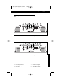
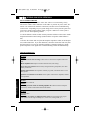
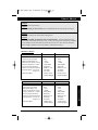
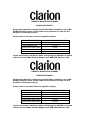
apx-dpx-update.qxp
8/18/2004
8:46 AM
Page 1
APX640.4/APX640.2/APX320.2/DPX1001.1
Owner/Installation Manual
apx-dpx-update.qxp
8/18/2004
8:46 AM
Page 2
APX640.4/640.2/320.2/DPX1001.1
Dear Customer,
Congratulations on your purchase of the world’s finest brand in the mobile electronic
industry. At Clarion we are committed to high-quality music reproduction, and we are
confident that you will be pleased with your purchase. Clarion’s extensive history in the
mobile electronic industry translates into products that are built to the highest of standards. These products provide optimum performance, which we are sure you will enjoy
for years to come. Thank you for making Clarion your car audio brand.
For maximum performance Clarion recommends having your amplifier installed
by an authorized Clarion dealer. Please read your warranty statement and retain
your original sales receipt as proof of purchase.
To learn more about Clarion’ complete line of car audio products, please visit us at our
Web site
www.clarion.com
INTRODUCTION
WARNING
Exposure to continuous sound levels of 85dB or higher may result in
hearing loss. Clarion products are capable of producing high sound
pressure levels, but please use your product at reasonable levels.
Please observe all local sound ordinances for your safety during the
operation of your vehicle.
2
apx-dpx-update.qxp
8/18/2004
8:46 AM
Page 3
Owner’s
Owner’sManual
Manual
TABLE OF CONTENTS
Introduction . . . . . . . . . . . . . . . . . . . . . . . . . . . . . . . . . . . . . . . . . 2
Description . . . . . . . . . . . . . . . . . . . . . . . . . . . . . . . . . . . . . . . . . 3
Installation, Mounting/Wiring Precautions . . . . . . . . . . . . . . . . . 4
Input Connections and Audio Control . . . . . . . . . . . . . . . . . . . . 5-8
Connections for Power and Speakers . . . . . . . . . . . . . . . . . . . . . 9-10
Applications . . . . . . . . . . . . . . . . . . . . . . . . . . . . . . . . . . . . . . . . 11-14
Setting the Gain, Crossover/Bass Boost . . . . . . . . . . . . . . . . . . . 15
Final System Checks, Troubleshooting . . . . . . . . . . . . . . . . . . . . 16
Product Specs . . . . . . . . . . . . . . . . . . . . . . . . . . . . . . . . . . . . . . . 17
Warranty Information . . . . . . . . . . . . . . . . . . . . . . . . . . . . . . . . . 18
DESCRIPTION
Clarion has crafted its car audio amplifier to fit a variety of system configurations. The following is a list of features:
DESCRIPTION
• Full frequency response with low distortion and exceptional
signal-to-noise performance.
• Advanced circuitry design features bridgeable outputs for use in a
variety of applications.
• Independent electronic crossovers, each with a 12dB (12/24dB - DPX1001.1)
per octave slope and full adjustment range from 50Hz to 5.8KHz, (50Hz to
580Hz - DPX1001.1) to aid in audio system design.
• Bass boost circuit to reinforce low frequency signals that may be lost
due to subwoofer box design.
• Adjustable input level controls with ground loop isolation, accepting a
wide range of input signals.
• Remote turn-on with “soft start” muting to prevent turn-on “thump”.
• Protection circuits for overheating and speaker shorts.
• 2-ohm load capable to drive a variety of speaker systems.
• Gold-plated input/output connectors and an external automotive- type
fuse.
• Aluminum heat sink for efficient heat dissipation.
• Low profile, compact size to accommodate space limitation.
3
apx-dpx-update.qxp
8/18/2004
8:46 AM
Page 4
APX640.4/640.2/320.2/DPX1001.1
INSTALLATION
This section lists mounting and wiring precautions prior to installing the Clarion
amplifier. These safeguards provide enough detail to complete an installation successfully. Do not attempt to install the amplifier yourself, if you do not have the necessary skills. Instead, see your authorized Clarion dealer for installation recommendations.
MOUNTING PRECAUTIONS
Although the Clarion amplifiers incorporate heat sinks and protection circuits, mounting the amplifier in a tight space without any air movement will result in damage to
the amp’s internal circuitry over time. Choose a site that provides adequate ventilation around the amplifier. For easy system setup, mount the amplifier so the frontpanel controls are accessible after installation.
In addition, observe the following precautions:
1. For the most efficient cooling, mount the amplifier so cool air runs along the length
of the fins rather than across them. Remember, any moving air will dissipate heat.
2. Mount the amplifier on a rigid surface. Avoid mounting to subwoofer enclosures or
areas prone to vibration. Do not install the amplifier on plastic or other combustible
materials.
3. Prior to drilling, make sure proposed mounting holes will not cut into the fuel tank,
fuel lines, brake lines (under chassis), or electrical wiring.
WIRING PRECAUTIONS
Read all wiring precautions. If you are not sure of the connections, contact your
authorized Clarion dealer.
1. Before installation, make sure the source unit’s Power switch is in the OFF position.
2. Disconnect the negative (-) lead of the battery before making any power connections.
PRECAUTIONS
3. When making connections, be sure that each connection is clean and secure.
Insulate final connections with electrical tape or shrink tubing. Failure to do so may
result in damage to your equipment.
4. A secure, clean ground connection is critical to the performance of your Clarion
amplifier. Use the shortest ground wire possible and securely connect to the vehicle’s
chassis to minimize resistance and avoid noise problems. Be sure to clean off any
paint prior to making this connection.
5. Add an external fuse on the amplifier’s positive (+) power lead and connect it as
close as possible to the vehicle’s (+) battery terminal. Use a fuse rated to the total current consumption of the amplifier(s). Adding an external fuse will protect the electrical system from short circuits that can result in a fire.
4
apx-dpx-update.qxp
8/18/2004
8:46 AM
Page 5
Owner’s Manual
INPUT CONNECTIONS AND AUDIO CONTROL
Clarion amplifiers contain connections for RCA Inputs and Audio Control as shown
below.
4
1
6
2
INPUT
L
8
3
0
55
15
550
7
5
9
CROSSOVER
110
APX320.2
240
dB
4V-8V
2V-4V
0.2V-2V
R
330
Hz
FREQ
RANGE
X1
X10
HIGH
Level
OFF
HP
LP
L & R (MONO)
BRIDGED (R IN)
L
STEREO
R
Figure 1-1 APX320.2 Input Connections and Audio Control
4
1
6
2
INPUT
9
APX640.2
240
15
R
4V-8V
2V-4V
0.2V-2V
dB
7
5
CROSSOVER
110
55
0
L
8
3
550
330
Hz
FREQ
RANGE
X1
X10
HIGH
Level
OFF
HP
LP
L & R (MONO)
BRIDGED (R IN)
L
STEREO
R
1.
2.
3.
4.
5.
RCA Input Jacks
Input Voltage Selector
Precise Frequency Selector
Gain Control
Input Mode
6.
7.
8.
9.
CONNECTIONS
Figure 1-2 APX640.2 Input Connections and Audio Control
Bass Boost Control
Speaker Level Inputs
Frequency Multiplier
X-Over Mode Switch
5
apx-dpx-update.qxp
8/18/2004
8:46 AM
Page 6
APX640.4/640.2/320.2/DPX1001.1
INPUT CONNECTIONS AND AUDIO CONTROL
Clarion amplifiers contain connections for RCA Inputs and Audio Control as shown
below.
17
5
3
2
INPUT
FRONT
(2 CH. IN)
REAR
0.2V-0.6V
0.6V-4V
2V-8V
FRONT
GAIN
L
HIGH
Level
6
REAR
GAIN
0
SOURCE
SELECT
2 CH.
BASS
BOOST
330
55
8
X1
X10
330
LP OFF
28 24
9
23
REAR
HIGH
Level
L & R MONO
BRIDGED (R L IN)
STEREO
+
L +
RHP
240
550
LP OFF
APX640.4
STEREO
BRIDGED (F R IN)
L & R SUM MONO
FREQ
FREQ Hz RANGE
110
HP
240
20 21
18
13
4 CH.
2 CH.
BASS
dB
FREQ Hz
110
55
550
12
FRONT
0.2V-0.6V
0.6V-4V
2V-8V
15
+
-L
+ R
-R
14
15
Figure 2-1 APX640.4 Input Connections and Audio Control
16
1
30
19
.2V-.6V
INPUT
INPUT
SENSITIVITY
.6V-2V
M IN
SPEAKER
LEVEL IN
R
USA
L
BASS
BOOST
FREQ Hz
SUBSONIC BASS
FILTER BOOST
0
XOVER
FREQ Hz
110
30
55
125
550
dB
MAX
+
- L
+
-R
15 31 22 25 29
2V-8V
GAIN
ON 15
OFF
XOVER
SLOPE
2-4 OHM
LOAD
240
330
12dB
24 dB
DPX1001.1
1 OHM
REM OTE
LEVEL
GND
26 27
Figure 2-2 DPX1001.1 Input Connections and Audio Control
CONNECTIONS
1. RCA Input Jacks
2. Front RCA Input Jacks
3. Rear RCA Input Jacks
4. Input Voltage Selector
5. Front Input Voltage Selector
6. Rear Input Voltage Selector
7. Precise Frequency Selector
8. Front Precise Frequency Selector
9. Rear Precise Frequency Selector
12. Front Input Mode
13. Rear Input Mode
14. Rear Input Selector
15. Bass Boost Control
16. Speaker Lever Inputs
17. Front Speaker Level Inputs
6
18.
19.
20.
21.
22.
23.
24.
25.
26.
27.
28.
29.
30.
31.
Rear Speaker Level Inputs
Gain Control
Front Gain Control
Rear Gain Control
X-Over Mode Switch
Front X-Over Mode Switch
Rear X-Over Mode Switch
X-Over Slope
Remote Level Control Port
Subsonic Filter
Frequency Range Multiplier
Impedance Load Selector
Input Sensitivity
Bass Boost Frequency
apx-dpx-update.qxp
8/18/2004
8:46 AM
Page 7
Owner’s Manual
The Input Connections are gold-plated RCA Jacks. The Gain Controls provide a
wide adjustment range to accommodate output levels from any source unit brand.
Precise Frequency Selector
The filter frequency markings on the front panel of the amplifier are for reference
purposes. If you would like to select the filter frequency with a higher level of precision, consult the chart in Figure 3 on this page. This chart gives you a more accurate frequency for each of the forty-one detented positions of the frequency selection
control.
• Gain Controls with Selectable Input Voltage
There are 2 settings for the "Gain" that must be
adjusted in order to maximize the power output of
the amplifier. The first step is to select the proper
input voltage and the second step is to adjust the
Gain dial.
CONNECTIONS
• Input Voltage Selector
A wide range of signal input voltages can be accommodated by the APX320.2, APX640.2, APX640.4
and DPX1001.1 input section (200mV - 8V). This
wide range is split up into three ranges, Figure 2,
accessible via switches located in the "Gain" of the
amplifier. The "0.2V-0.6V" position on the switch
selects an input sensitivity range between 200mV
and 600mV, the "0.6V-2V" position on the switch
selects an input sensitivity range between 600mV
and 2V and the "2V-8V" position on the switch
selects an input sensitivity range between 2V and
8V. This means that the "Gain" rotary control will
operate within that voltage window. If you are using
an aftermarket source unit with RCA outputs, make
sure you select the proper voltage selection range.
For example, if the RCA voltage of the aftermarket
head unit is rated at 4 volts, set the switch at
"2V-8V".
Figure 3 - Detent Chart
7
apx-dpx-update.qxp
8/18/2004
8:46 AM
Page 8
APX640.4/640.2/320.2/DPX1001.1
• Load Selector
Please note that when configuring the DPX1001.1 amplifier, the LOAD SELECTOR switch
must be set in the correct position in order for the amplifier to function properly. Please refer
to the chart below for specific settings.
SUBWOOFER IMPEDANCE
LOAD SELECTOR SWITCH SETTING
2-OHM Bridged Load
4~8-OHM Bridged Load
1-OHM Load on each output
2-OHM Load on each output
4 OHM Load on each output
1 OHM
2-4 OHM
1 OHM
2-4 OHM
2-4 OHM
• Gain Dial
Located next to the input voltage selector, is a rotary control labeled "Gain". Once the
appropriate input voltage range has been selected, this rotary control can be used to
match the source unit's output voltage to the input stage of the amplifier for maximum
clean output. Rotating the control clockwise will result in higher sensitivity (louder for
a given input voltage). Rotating the control counter-clockwise will result in lower sensitivity (quieter for a given input voltage). After using this procedure, you can then
adjust the level of the amplifier by adjusting the input sensitivity downward, if the
amplifier requires attenuation to achieve the desired system balance. Do not increase
the "Gain" setting for any amplifier in the system beyond the maximum level. Doing
so will result in audible distortion and possible speaker damage.
CONNECTIONS
• Bass Boost Control
The amplifier also features a “high-Q” (i.e., narrow frequency band) Bass Boost circuit. It acts much like an equalizer with a switchable gain fixed at 45Hz. Use this
feature to tune low-frequency audio response to compensate for a less than ideal subwoofer enclosure design. The added boost produces rich, full bass tones that are normally difficult to reproduce in the car audio environment. NOTE: If Bass Boost is
undesired, set Bass Boost to OFF.
• X-Over Mode Switches - These switches are equipped with 12dB per octave electronic filters for precise frequency attenuation with minimal phase distortion. Each
filter is activated by sliding the X-Over Mode Switch to either HP or LP.
• Speaker Level Inputs - These provide connections for a high-level stereo source.
These connections are provided for installations when the source unit does not have
RCA outputs.
WARNING:
When using the speaker (high-level) inputs, the Black wire must be grounded at the radio.
Failure to do so will result in noise and/or improper operation.
8
apx-dpx-update.qxp
8/18/2004
8:47 AM
Page 9
Owner’s Manual
CONNECTIONS FOR POWER AND SPEAKERS
The rear panel of Clarion’s amplifiers contain power and speaker connections as
shown below.
3
4
L
4
2
MIN + MIN
6
5
7
8
R
2
MIN +
30 AMP MAX
APX320.2
Figure 4-1 APX320.2 Connections for Power and Speakers
3
4
L
4
2
MIN + MIN
6
5
7
8
R
2
MIN +
25x2
AMP MAX
APX640.2
1. Left Front Speaker Output
2. Right Front Speaker Output
3. Left Speaker Output
4. Right Speaker Output
5. Remote Turn-On Input
CONNECTIONS
Figure 4-2 APX640.2 Connections for Power and Speakers
6. Ground Input
7. Battery + 12V Input
8. Fuse
9. Left Rear Speaker Output
10. Right Rear Speaker Output
9
apx-dpx-update.qxp
8/18/2004
8:47 AM
Page 10
APX640.4/640.2/320.2/DPX1001.1
CONNECTIONS FOR POWER AND SPEAKERS
The rear panel of Clarion’s amplifiers contain power and speaker connections as
shown below.
1
6
2
5
7
8
R
L
4
2
MIN + MIN
2
MIN +
25x2
AMP MAX
APX640.4
FRONT
REAR
9
10
Figure 5-1 APX640.4 Connections for Power and Speakers
4
3
1
MIN
1
MIN
POWER
5
7
GND
REM
+12V
DPX1001.1
RIGHT
LEFT
USA
6
BRIDGED
2
MIN
CONNECTIONS
Figure 5-2 DPX1001.1 Connections for Power and Speakers
1. Left Front Speaker Output
2. Right Front Speaker Output
3. Left Speaker Output
4. Right Speaker Output
5. Remote Turn-On Input
10
6. Ground Input
7. Battery + 12V Input
8. Fuse
9. Left Rear Speaker Output
10. Right Rear Speaker Output
apx-dpx-update.qxp
8/18/2004
8:47 AM
Page 11
Owner’s Manual
Bridged-Mono Subwoofer System
L
4
2
MIN + MIN
R
2
MIN +
30 AMP MAX
BASS
BOOST
CROSSOVER
110
55
0
240
550
15
APX320.2
330
dB
FREQ
RANGE
FREQ
Hz
L & R (MONO)
OFF
X1
HP
X10
BRIDGED (R IN)
STEREO
LP
Set X-Over Mode to LP and adjust
frequency to subwoofer specifications.
R
2
MIN +
25x2
AMP MAX
BASS
BOOST
0
CROSSOVER
110
55
240
550
15
APX640.2
330
dB
FREQ
Hz
FREQ
RANGE
OFF
X1
HP
X10
LP
L & R (MONO)
BRIDGED (R IN)
STEREO
APPLICATIONS
L
4
2
MIN + MIN
Set X-Over Mode to LP and adjust
frequency to subwoofer specifications.
Figure 6 - In this application, the amplifier is bridged for mono operation to drive a
subwoofer.
11
apx-dpx-update.qxp
8/18/2004
8:49 AM
Page 12
APX640.4/640.2/320.2/DPX1001.1
2-Channel Full-Range or Subwoofer System
(APX320.2 or APX640.2)
R
L
4
2
MIN + MIN
2
MIN +
30 AMP MAX
L - Full Range
APX320.2
R - Full Range
CROSSOVER
110
55
0
240
550
15
330
dB
OFF
HP
Hz
LP
or
CROSSOVER
110
55
0
15
240
550
330
dB
OFF
HP
Hz
LP
or
CROSSOVER
APPLICATIONS
15
110
55
0
240
550
330
dB
OFF
Hz
HP
LP
Figure 7 - In this application, the amplifier is used in stereo and drives two full-range (or
satellite, or subwoofer) speakers.
NOTE: A passive crossover must be used with satellite speakers.
12
apx-dpx-update.qxp
8/18/2004
8:51 AM
Page 13
Owner’s Manual
4-Channel High Power System
R
L
4
2
MIN + MIN
2
MIN +
25x2
AMP MAX
APX640.4
FRONT
REAR
FL - Full Range
RR - Full Range
FR - Full Range
RL - Full Range
FREQ Hz
110
55
FREQ Hz
110
HP
240
550
240
330
REAR
X1
X10
LP OFF
330
APPLICATIONS
550
FREQ
RANGE
55
Figure 8 - In this application, the APX640.4 is used as a 4-channel amplifier to drive
four full-range speakers in stereo.
13
apx-dpx-update.qxp
8/18/2004
8:52 AM
Page 14
APX640.4/640.2/320.2/DPX1001.1
1
MIN
1
MIN
POWER
GND
REM
+12V
DPX1001.1
RIGHT
LEFT
BRIDGED
2
MIN
USA
XOVER
FREQ Hz
55
550
110
XOVER
SLOPE
240
330
12dB
24 dB
R - Subwoofer
CONNECTIONS
L - Subwoofer
Figure 9 - In this application, the DPX1001.1 is used to drive a pair of subwoofers.
14
apx-dpx-update.qxp
8/18/2004
8:52 AM
Page 15
Owner’s Manual
SETTING THE GAIN
After completing the installation, follow these steps to set the Gain Control and then
perform the Final System Checks.
1. Turn the Gain Control all the way counter-clockwise.
2. Select the proper input voltage as described on page 7, (Gain Control with
Selectable Input Voltage)
3. Turn the vehicle’s Ignition Switch to the ON position. Then turn the ON/OFF
Switch on the source unit to the ON position. Set all Tone or Equalization Controls
to “flat” positions and turn Loudness off.
4. Play a CD or Tape and set the Volume Control at 75% of full level.
NOTE: If the system uses an equalizer set all frequency controls to the “flat”
position.
5. Slowly increase the Gain Control. Stop when you hear a slight distortion of audio.
SETTING THE CROSSOVER
The Clarion amplifiers feature fully adjustable crossovers. To set the crossovers, follow these steps:
1. Using the X-Over Mode Switch, select the desired mode: LP for Low Pass, HP for
High Pass or OFF for Full Range.
2. Using the Freq (Hz) Selection Control, select the desired frequency.
SETTING THE BASS BOOST
1. Initially set the Bass Boost control to its OFF position.
2. Listen to a variety of music styles (e.g., Rock, Rap, etc.) and switch the Bass Boost
control ON until a noticeable increase in low bass response is realized.
SETTING
CAUTION: If you hear a “pop” (due to speaker over-excursion) adjust switch to
lower the Bass Boost to prevent speaker damage.
15
apx-dpx-update.qxp
8/18/2004
8:52 AM
Page 16
APX640.4/640.2/320.2/DPX1001.1
FINAL SYSTEM CHECKS
1. Start the engine and turn on the source unit. After a two-second delay, slowly
increase the volume control and listen to the audio. If you hear any noise, static, distortion or no sound at all, check the connections, and also refer to troubleshooting
section below. Depending on your system design, the levels may become quite loud
even at low volume control settings. Until you get an “audio feel” of the system’s
power, use care when adjusting controls.
2. Turn the balance controls to their extreme positions and listen to the results. Audio
output should match control settings (audio from the left speaker when balance is
left).
3. Increase the volume and verify that the amplifier reproduces audio (at full frequencies) without distortion. If you hear distortion, check the connections and verify that
the gain control is set correctly. Another possibility is damaged speakers or underpowered speakers. Once again refer to troubleshooting section for additional help.
TROUBLESHOOTING
Problem
No Audio.
Solution
Low or no remote turn-on voltage: Check remote connections at amplifier and source
unit.
Blown amplifier fuse: Replace with new fast-blow fuse (same rating).
Power wires not connected: Check battery and ground wiring at amplifier; also check
battery connections.
Speaker leads shorted: Check speaker continuity to ground, it should not show a common ground.
Speakers not connected or are blown: Check speaker connections at amplifier, measure
coil impedance.
TROUBLESHOOTING
Problem
Audio cycles on and off.
Solution
Thermal protection circuits are shutting amplifier off: Check location for adequate
ventilation; consult an authorized Clarion Audio Dealer.
Problem
Distorted audio.
Solution
Gain is not set properly, or damaged speaker cones: Review Setting Gain; inspect
each speaker cone for signs of damage (i.e., frozen cone, burning smell, etc.)
16
apx-dpx-update.qxp
8/18/2004
8:52 AM
Page 17
Owner’s Manual
Problem
Amplifier fuse keeps blowing.
Solution
Incorrect wiring or short circuit: Review Installation and check all wiring connections.
Problem
Whining or ticking noise in the audio with engine on.
Solution
Amplifier is picking up alternator noise or radiated noise: Turn down input gain and
move audio cables away from power wires. Check power and ground connections on amplifier and install an in-line noise filter on source unit’s power wire. Also check the alternator
and/or voltage regulator. Test for weak battery or add water to battery.
MODEL
APX320.2
APX640.2
Maximum Power Output
Continuous Power Output
THD @ Rated Output (%)
Sound to Noise Ration (A wtg)
Frequency Response(+/-1dB)
Line Level Input Sensitivity
Speaker Level Input Sensitivity
Input Impedance - Low Level
High Level
Output Impedance
320
80x2
<.05%
>110dB
10Hz-50kHz
200mV-8V
400mV to 16V
12k Ohms
395 Ohms
2 Ohms Stereo
4 Ohms Bridged
640
160x2
<.05%
>110dB
10Hz-50kHz
200mV-8V
400mV to 16V
12k Ohms
395 Ohms
2 Ohms Stereo
4 Ohms Bridged
MODEL
APX640.4
DPX1001.1
Maximum Power Output
Continuous Power Output
THD @Rated Output (%)
Sound to Noise Ration (A wtg)
Frequency Response (+/-1dB)
Line Level Input Sensitivity
Speaker Level Input Sensitivity
Input Impedance - Low Level
High Level
Output Impedance
640
80x4
<.05%
>110dB
10Hz-50kHz
200mV-8V
400mV to 16V
12k Ohms
395 Ohms
2 Ohms Stereo
4 Ohms Bridged
1000
250x2
<.05%
>95dB
10Hz-50kHz
200mV-8V
400mV to 16V
12k Ohms
395 Ohms
1 Ohms Stereo
2 Ohms Bridged
PRODUCT SPECS
PRODUCT SPECS
17
apx-dpx-update.qxp
8/18/2004
8:52 AM
Page 18
WARRANTY INFORMATION
This product is warranted against all defects in material workmanship for a period of one year
from the date of original purchase. Clarion ProAudio products, except for speakers, are covered
by a two-year warranty when installed by an authorized Clarion dealer. The conditions of this
warranty and the extent of responsibility of Clarion Corporation under this warranty are as follows:
1.PROOF OF DATE OF PURCHASE WILL BE REQUIRED FOR WARRANTY SERVICE
OF THIS PRODUCT. IN CASE OF 2-YEAR WARRANTY FOR CLARION PROAUDIO
PRODUCT, PROOF OF INSTALLATION BY AUTHORIZED DEALER IS REQUIRED.
INFORMATION ABOUT CLARION AUTHORIZED WARRANTY SERVICE CENTERS
MAY BE OBTAINED BY CONTACTING OR WRITING CLARION CORPORATION AT
THE ADDRESS LISTED BELOW.
2.This warranty will become void if service performed by anyone other than an approved
Clarion Warranty Service Center results in damage to product.
3.This warranty does not apply to any product which has been subject to misuse, neglect or
accident, or which has had the serial number altered, defaced or removed, or which has been
connected, installed, adjusted or repaired in a manner that is not in accordance with the instructions furnished by Clarion Corporation.
4.This warranty does not cover car static or other electrical interferences, tape head cleaning or
adjustments, or labor costs for the removal or reinstallation of the unit for repair.
5.The sole responsibility of Clarion Corporation under this Warranty shall be limited to the
repair or replacement thereof, at the sole discretion of Clarion Corporation.
6. If it becomes necessary to send the product or any defective part to Clarion Corporation or
an authorized warranty service station, the product must be shipped in its original carton or
equivalent carton, fully insured, with shipping charges prepaid. Clarion Corporation will not
assume any responsibility for any loss or damage incurred in shipping.
7. ALL IMPLIED WARRANTIES EXCEPT TO THE EXTENT PROHIBITED BY APPLICABLE LAW SHALL HAVE NO GREATER DURATION THAN THE WARRANTY PERIOD
SET FORTH ABOVE. UNDER NO CIRCUMSTANCES SHALL CLARION CORPORATION BE LIABLE FOR ANY LOSS OR DAMAGE, DIRECT OR CONSEQUENTIAL,
ARISING OUT OF THE USE OR INABILITY TO USE THE PRODUCT. BECAUSE SOME
STATES DO NOT ALLOW LIMITATIONS ON HOW LONG AN IMPLIED WARRANTY
LASTS OR EXCLUSIONS OR LIMITATIONS OF INCIDENTAL OR CONSEQUENTIAL
DAMAGES, THE ABOVE LIMITATIONS OR EXCLUSIONS MAY NOT APPLY TO YOU.
WARRANTY
8.THIS WARRANTY GIVES YOU SPECIFIC LEGAL RIGHTS, AND YOU MAY ALSO
HAVE OTHER RIGHTS WHICH VARY FROM STATE TO STATE.
9.For instructions on how to obtain warranty service, please call 1-800-668-5612 or visit our
Web site at www.clarion.com for a listing of Authorized Warranty Service Centers in your area,
or contact the Clarion Customer Service Manager at the address listed below:
Clarion Canada Inc.
2239 Winston Park Drive
Oakville, ON L6H 5R1
18
apx-dpx-update.qxp
8/18/2004
8:52 AM
Page 19
Clarion Canada Inc.
2239 Winston Park Drive
Oakville, ON
L6H 5R1
1-800-668-5612
www.clarion.com
Amp Manual - Rev. 04/26/04
OWNER’S MANUAL SUPPLEMENT
CLARION DPX1001.1
Please note that when configuring the DPX1001.1 amplifier, the LOAD
SELECTOR switch must be set in the correct position in order for the
amplifier to function properly.
Please refer to the chart below for specific settings.
SUBWOOFER IMPEDANCE
2-OHM Bridged Load
4~8-OHM Bridged Load
1-OHM Load on each output
2-OHM Load on each output
4 OHM Load on each output
LOAD SELECTOR SWITCH SETTING
1 OHM
2-4 OHM
1 OHM
2-4 OHM
2-4 OHM
If you need further assistance when configuring the DPX1001.1 please
contact Clarion/UNGO Product Support at 1-800-668-5612 ext. 229