1
EVS-2
Electronic Vibration Switch
Installation and Operations Manual
00-02-0841
2013-01-14
Section 20
In order to consistently bring you the highest quality, full featured products, we reserve the right to change our
specifications and designs at any time. The latest version of this manual can be found at www.fwmurphy.com.
Warranty – A limited warranty on materials and workmanship is given with this FW Murphy product.
A copy of the warranty may be viewed or printed by going to http://www.fwmurphy.com/warranty.
Please read the following information before installing the EVS-2.
This installation information is intended for all EVS-2
models. A visual inspection of this product before
installation for any damage during shipping is
recommended.
Disconnect all power and be sure machine is inoperative
before beginning installation.
Installation is to be done only by qualified technician
according to the National Electrical Code.
Observe all Warnings and Cautions at each section in
these instructions.
Please contact FW MURPHY immediately if you have any
questions.
FW MURPHY has made efforts to ensure the reliability of the Electronic Vibration Switch (EVS2) and to recommend safe usage practices in system applications. Please note that in any
application, operations and device failures can occur. These failures may result in full control
outputs or other outputs which may cause damage to or unsafe conditions in the equipment or
process connected to the EVS-2.
Good engineering practices, electrical codes, and insurance regulations require that you use
independent external protective devices to prevent potentially dangerous or unsafe conditions.
Assume that the Murphy EVS-2 system can fail with outputs full on, outputs full off, or that other
unexpected conditions can occur.
Table of Contents
Product Information ...................................................................................................................1
Murphy EVS-2 Overview ..............................................................................................1
EVS-2 Characteristics and Orientation .........................................................................2
Installation ...................................................................................................................................3
Mounting ......................................................................................................................3
Mounting Options .........................................................................................................4
Bracket Proposals ........................................................................................................5
Mounting Examples ......................................................................................................5
Plug Options.................................................................................................................6
Wiring ...........................................................................................................................6
Settings......................................................................................................................................10
Setting the Set-Point in Inches Per Second (IPS) Peak .............................................10
Setting of Alarms ........................................................................................................13
Vibration Limits Based on Class of Equipment Based on ISO 10816-3 .....................14
Equipment Manufacturer Recommended Settings .....................................................16
Specifications ...........................................................................................................................17
THIS PAGE INTENTIONALLY LEFT BLANK
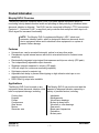
Product Information
Murphy EVS-2 Overview
The Murphy Electronic Vibration Switch (EVS-2) protects against equipment failure by
monitoring velocity-based vibration levels and providing an early warning or shutdown when
abnormal vibration is detected. The EVS-2 can be connected to Murphy’s TTD annunciator,
Centurion , Centurion PLUS or any third- party controller that accepts a switch input or 420mA signal for increased functionality.
NOTE: The Murphy EVS-2 complements Murphy’s VS2 shock and
excessive vibration switch, which is designed to detect an abnormal shock
due to equipment failure and to shutdown other equipment in a system to
prevent further damage.
Features
Universal use, can be mounted horizontal, vertical or at any other angle
Piezoelectric-crystal internal sensor with built-in microelectronics for reduced noise
sensitivity
Electronically integrated output signal that measures and trips on velocity (IPS peak)
Two independently adjustable output channels
Shutdown setpoint measured in velocity (IPS peak)
4-20 mA output for continuous monitoring capability
Solid-state outputs for setpoint trip
Adjustable time delay to prevent false tripping on high-vibration start-ups or nonrepetitive transient events
RAW 100mV/g output also available
Applications
The Murphy EVS-2 can be used on any
equipment where abnormal vibration could
lead to equipment damage, including:
Cooling fans
Engines
Pumps
Compressors
Gear boxes
Motors
Generator sets
Section 20
2013-01-14
The Murphy EVS-2 can monitor and alert the
operator of abnormal vibration caused by a
variety of possible factors, including:
Imbalance
Misalignments
Worn sleeve bearings
Broken tie down bolts
Worn ball or roller bearings
Gear mesh
Blade pass frequencies
Detonation
Broken parts
00-02-0841
-1-
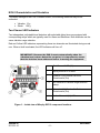
EVS-2 Characteristics and Orientation
To prevent damage to the EVS-2 vibration switch, the following vibrations may not be
exceeded:
Vibration 15 g
Shock 150 g
Two-Channel LED Indicators
Two independent, adjustable level detectors with selectable delay times are equipped with
corresponding relays which are typically used for Alarm and Shutdown. Both channels use the
same vibration range selection.
Red and Yellow LED indicators representing these two channels are illuminated during normal
use. When a fault is activated, the LED indicators will turn off.
IMPORTANT! Because the EVS-2 resets automatically when the
vibration level returns below the set point, it is important to ensure
that the fault has been addressed before restarting the equipment.
1
Red Channel 2 LED (K2)
2
Spring terminal 16-24 AWG.
3
Channel 2 (K2) Vibration Set Point
Potentiometer (Pot)
4
DIP switches for vibration ranges and time
delays.
5
Channel 1 (K1) Vibration Set Point
Potentiometer (Pot)
6
Yellow Channel 1 (K1) LED
Figure 1 – Inside view of Murphy EVS-2 component locations
Section 20
2013-01-14
00-02-0841
-2-
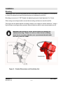
Installation
Mounting
The Murphy EVS-2 must be mounted and set in accordance with the guidelines in this manual
to obtain the desired and specified performance and equipment protection.
Mounting occurs via a ½” NPT thread, the tightening torque is hand tight plus 2 to 3 turns.
When using a mounting bracket, ensure that mounting surfaces are smooth and flat.
Care must also be taken that the mounting surface is not subject to natural vibrations. Using a
high stiffness mounting surface prevents natural vibrations which cause measurement errors.
WARNING! Exceeding the torque specification will damage the
aluminum housing. If there is concern of the device becoming
loose due to excessive vibration, use a permanent thread locker
such as Loctite 271 (RED).
Figure 2 – Product Dimensions and Sensitivity Axis
Section 20
2013-01-14
00-02-0841
-3-
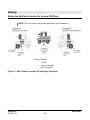
Mounting Options
The following diagrams illustrate example mounting options for the EVS-2 using a simple pipe
plug welded to the machine surface or a bracket with the special adapter provided for drilled
and tapped surface mount.
NOTE: The special adapter is available for sale. Also note that a hollow
pipe close nipple is NOT recommended for installations.
Section 20
2013-01-14
00-02-0841
-4-
Bracket Proposals
Mounting Examples
Legend: C=Compressor, E=Engine
Compressor
Cx (Compressor) = Crankshaft endplay
Cy = Main Bearings, Rod Bearings
Cz = Main Bearings
Section 20
2013-01-14
Engine
Ex (Engine) = Crankshaft endplay
Ey = Main Bearings
Ez = Main Bearings, Detonation, Rod Bearings
00-02-0841
-5-
Plug Options
High-pressure (non-hollowed), forged steel pipe
plug permanently welded to equipment or
bracket surface. Be sure weld is clear of
threads for maximum thread engagement.
Optional Adapter available from FW Murphy:
½” NPT, High-pressure (non-hollowed), steel
pipe plug, Male x Male to be used for direct
mount to equipment with a ½” NPT threaded
pilot hole.
Wiring
The method chosen to electrically connect to the switch should be mechanically flexible to
eliminate the measurement of vibration induced from conduit and to provide a moisture barrier
as well. Although Sealtite and other flexible conduit have been used successfully, in areas of
extreme humidity or moisture Murphy recommends using an “SO” type cable along with a Div.
2 suitable rain-tight CGB Gland/Strain relief fitting. No stress should be possible on the wiring
to the terminal block. If such protection is not provided by the conduit system, some form of
stress relief must be installed.
WARNING! Certification compliance requires the use of a cable
gland and strain relief fitting.
To assure compatibility with EMI compliance standards, any signal level wiring such as
transducer or 4-20 mA wiring should use shielded cable in EMI proof conduit, separate from
any power wiring except the DC power for the EVS-2. AWG 16-26 wire can be used.
NOTE: It is strongly recommended that this cabling be installed using the
method defined in the Shipboard Cable/Cord Installation document (0002-0725 rev 08/2010). That document can be found by following this link
http://www.fwmurphy.com/evs-2.
Section 20
2013-01-14
00-02-0841
-6-
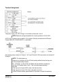
Terminal Assignment
The power supply +24 VDC voltage is connected via terminals 1 and 2.
NOTE: Minimum voltage acceptable for normal operation is 20-30 VDC.
A DC to DC converter can be used for 12V systems. Murphy recommends the Phoenix
Contact MINI-PS-12-24DC/24DC/1 or equivalent.
Non-latching relay outputs for Channel 1 (K1) and Channel 2 (K2) are present on terminals 3
through 8.
NOTE: On initial power-up:
Relays do not activate until the 4-20mA reading settles below the trip point
for the corresponding channel.
Ex: If Channel 1 is set at 50%, the Relay will not activate on power-up
until the 4-20 settles below 12mA. This could take approximately 7
seconds.
If the trip point is higher (90%) then it will take less time.
If the trip point is lower (10%) then it will take more time.
4-20mA Output requires approximately 30 seconds to reach full resolution.
Section 20
2013-01-14
00-02-0841
-7-
Figure 3 - EVS-2 Hook-up (showing only how to wire Channel 1 {K1})
Section 20
2013-01-14
00-02-0841
-8-
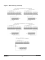
Figure 3 - EVS-2 Hook-up (continued)
Section 20
2013-01-14
00-02-0841
-9-
Settings
Setting the Set-Point in Inches Per Second (IPS) Peak
NOTE: The unit must be set per the application upon installation.
Factory Settings:
- 1.5 IPS
- 1 sec. time delay
- 50% limit value
Figure 4 – EVS-2 Detail for setting IPS and Delay Set-points
Section 20
2013-01-14
00-02-0841
- 10 -
Procedure
Refer to the monitored machine recommended setting and mounting information and make
appropriate adjustments. To adjust the setpoint, open the Murphy EVS-2 cover and follow
these steps:
Select the appropriate delay settings and ranges using the DIP switches.
A. Time delays for each channel are set to either 1 second or 5 seconds via DIP switch 1 for
Channel 1, and DIP switch 5 for Channel 2.
(ON=1 sec; OFF=5 sec)
B. Select a range that allows normal vibration and preferred trip points to exist near mid range.
Range selection affects both channels. The measurement range in vibration velocity (in/sec
peak) is established when:
DIP switch 2: ON=0.75 in/sec peak (DIP switches 3, 4=OFF)
DIP switch 3: ON=1.50 in/sec peak (DIP switches 2, 4=OFF)
DIP switch 4: ON=3.00 in/sec peak (DIP switches 2, 3=OFF)
Use a slotted, narrow blade screwdriver to adjust both of the Vibration Set Point potentiometers:
To increase the Vibration Set Point, turn the potentiometer clock-wise.
To decrease the Vibration Set Point, turn the potentiometer counter clockwise.
Make sure that the machine to be monitored is powered on and in normal operation.
Determining & Adjusting the Delay Setpoint (1 or 5 Seconds)
The Delay Setpoint value can define the line between sensitivity and nuisance faults. A 1
second delay allows a potentially catastrophic failure to be detected quickly. A 5 second delay
helps prevent normal start-up vibrations from triggering an alarm. An evaluation of these two
conditions should be made for each unique installation before setting the Delay Setpoint.
If start-up vibrations exceed the established threshold limits and trigger the alarm at the
desired delay set-point, wire the EVS-2 to a “Class B” input timer on a Murphy annunciator or
controller. If used with a PLC system, the input can be timed out for startup.
There are two independently adjustable channels. Each channel has its own delay setting.
Useful Vibration Formulas
V = fD
V = 61.44 g/f
g = 0.0511 f2D
g = 0.0162 Vf
D = 0.3183 V/f
D = 19.57 g/f2
Section 20
2013-01-14
D (displacement) = inches peak-to-peak
V (velocity)=inches/second=IPS
g (acceleration) = 386.1 inches / second2
f (frequency) = RPM/60
rms (root mean squared) = 0.707 x peak
peak-to-peak = 2 x peak
= 3.1416
00-02-0841
- 11 -
Pot Settings
The Vibration Setpoint potentiometers (pots) adjust the level detection based on the scale set
in DIP switches 2 through 4. These pots adjust to a percentage of the scale (range) chosen. If
0 to 1.5 IPS is selected as the range, then a pot setting of 50% would cause the EVS-2 to trip
at a vibration of 0.75 IPS. Figures 5 and 6 illustrate these pot settings for the EVS-2.
Figure 5
Figure 6
Section 20
2013-01-14
00-02-0841
- 12 -
Setting of Alarms
The alarm values may vary considerably, up or down, for different machines. The values
chosen will normally be set relative to a baseline value determined from experience for the
measurement position or direction for that particular machine.
As shown in Figure 7, it is recommended that the alarm value be set higher than the baseline
by an amount equal to 25% of the upper limit for Zone B. If the baseline is low, the alarm
should be below Zone C.
Where there is no established baseline (for example with a new machine) the initial alarm
setting should be based either on experience with other similar machines or relative to agreed
acceptance values.
After a period of time, the steady-state baseline value will be established and the alarm setting
should be adjusted accordingly.
Recommended Alarm Settings
The following are guidelines based on industry standards. Actual settings will vary depending
on mounting and unit installation. (Note: Refer to the Appendix for recommended settings by
specific manufacturers.) Experience with a given installation should be the major factor in
deciding the settings.
It is recommended that the alarm value should not normally exceed 1.25 times the upper limit
of zone B.
Section 20
2013-01-14
00-02-0841
- 13 -
Vibration Limits Based on Class of Equipment Based on ISO 10816-3
Figure 7 – Vibration Limits
Section 20
2013-01-14
00-02-0841
- 14 -
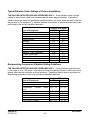
Typical Vibration Alarm Settings of Various Installations
THE VALUES LISTED BELOW ARE GUIDELINES ONLY – Actual vibration limits must be
related to stress levels, which can be measured with strain gage equipment. In general, if
vibration levels are below the guidelines mentioned below, the stress levels are well below the
fatigue level of the equipment. If vibration problem is perceived, a spectral analysis should be
performed on the unit by a qualified specialist.
Type of Equipment
Compressor, Centrifugal
Compressor, Reciprocating
Conveyors
Electric Motors
Engines
Fans, Blowers
Gear Boxes
Generator Sets, Electric Driven
Generator Sets, Engine Driven
Machine Tools (unloaded)
Pumps, Centrifugal
Pumps, Gear
Pumps, Reciprocating
Turbines
Velocity (IPS peak)
LOW
HIGH
0.2
0.4
0.5
0.7
0.3
0.5
0.1
0.3
0.5
0.7
0.2
0.4
0.1
0.3
0.2
0.3
0.5
0.7
0.05
0.2
0.1
0.3
0.1
0.3
0.5
0.7
0.05
0.2
Reciprocating Compressor Vibration Setting Guidelines
THE VALUES LISTED BELOW ARE GUIDELINES ONLY – Cyclical failures generally occur
in the range of 10 to 100 cycles. High velocity at high frequency will result in failure at a much
greater rate than high velocities at a low frequency. Experience should also be a guideline in
determining acceptance limits for a particular compressor package.
Type of Equipment
Motor Frame
Compressor Frame
Compressor Cylinder (outer
end)
Pulsation bottles (outer center)
Skid Frame (top)
Scrubber (6’-6” elevation)
Piping (saddles and 12” spans)
PSV’s (top of valves)
Section 20
2013-01-14
Velocity (IPS peak)
(IPS)
(mm/sec)
0.3 – 0.5
8 – 12
0.2 – 0.3
5–8
0.5 – 1.0
12 – 25
0.5 – 1.0
0.1 – 0.3
0.8 – 1.0
0.5 – 0.8
0.6 – 0.8
12 – 25
2.5 – 8
20 – 25
12 – 20
15 - 20
00-02-0841
- 15 -
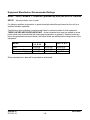
Equipment Manufacturer Recommended Settings
ARIEL: SKID, FRAMES, CYLINDERS (provided by Ariel) MICROLOG CMVA60
SETUP: Velocity ins/sec, zero to peak
If a vibration problem is perceived, a spectral analysis should be performed on the unit by a
qualified vibration specialist.
The following chart indicates overall average limits for various models of Ariel equipment.
THESE VALUES ARE GUIDELINES ONLY - Actual vibration limits must be related to stress
levels, which can be measured with strain gage equipment. In general, if vibration levels are
below the guidelines mentioned below, the stress levels are well below the fatigue level of the
equipment.
JG, A, M, N, JGJ, H, E, T,
JGC, D, B, V
P, Q, R, W
K
Skid
<0.10 IPS
<0.15 IPS
<0.20 IPS
Compressor Frame
<0.20 IPS
<0.40 IPS
<0.20 IPS
Compressor Cylinder
<0.45 IPS
<0.80 IPS
<1.0 IPS
Chart effective 10/01/00, Check latest limits on Ariel Web Site.
Model
Other manufacturer’s data will be provided as authorized.
Section 20
2013-01-14
00-02-0841
- 16 -
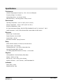
Specifications
Performance
Vibration Range (Adjust Jumper S1): 0.75, 1.50 or 3.00 IPS/peak
Frequency Range: 5 to 1000 Hz
Analog Output (Rload): 4 to 20 mA ≤ 500 Ω
Raw Signal (Rload): 100 mV/g (offset + 5VDC) ≤ 20 kΩ
Environment
Operating Temperature: -22°F to +185°F (-30C to +85C)
Storage Temperature: -40°F to +185°F (-40°C to +85°C)
Enclosure Classification: IP68
EC Type Certification # Rating: BSI 07 ATEX 1532458U EX d IIC T6 , Ex tD A21 T 100°C
Cable Connection: ½ NPT, IP66, IRA 06 ATEX 1188 X SIRA 07 ATEX 4327 X
Electrical
Sensor Type: Accelerometer
Power Required: 20 to 30 VDC
Current Draw: <40 mA
Electrical Connectors: Spring Terminals
Relay
Switch Contact Capacity: 30 VDC/1A, 150 VAC/0.46 A
Relay Function: Non-Latching
Threshold Set Point: 10 to 100% of Alarm Set Point
Normally Energized (NE): Fail Safe
Time Delay (Adjust DIP Switch S1 and S5): 1 or 5 seconds
Physical
Housing Material: Aluminum/Epoxy Paint (Red)
Weight: 1.54 lbs. (0.7 kg)
Size (H x W): 4.9 in x 3.9 in (125 x 100 mm)
Mounting Threads: ½ “ NPT Female, ½” NPT Male/Male SS
Indicators
Alarm (LED): Yellow
Shutdown (LED): Red
Section 20
2013-01-14
00-02-0841
- 17 -
THIS PAGE INTENTIONALLY LEFT BLANK
THIS PAGE INTENTIONALLY LEFT BLANK