1
T400 Controller Facilities Manual
SIEMENS TRAFFIC CONTROLS LIMITED
Sopers Lane
POOLE Dorset.
BH17 7ER
SYSTEM/PROJECT/PRODUCT: T400 CONTROLLER
T400 CONTROLLER
FACILITIES MANUAL
PREPARED: A.Pickering
APPROVED: J.P.Burgess
FUNCTION: Senior Engineer
FUNCTION: Engineering Manager
SIGNATURE:
SIGNATURE:
ISSUE:
1
2
3
4
5
6
7
8
CHANGE REF.:
DATE:
83/15948
83/16122
83/16700
83/16955
83/17014
83/17147
83/18623
16/08/89
15/02/91
13/06/91
24/09/92
18/12/92
20/01/93
23/03/93
22/05/96
9
APPROVED BY:
Jan 1999
Siemens Traffic Controls Limited 1995 All rights reserved.
The information contained herein is the property of Siemens Traffic Controls Limited and is
supplied without liability for errors or omissions and no part may be reproduced, used or
disclosed except as authorized by contract or other written permission. The copyright and the
foregoing restriction on reproduction, use and disclosure extend to all the media in which this
information may be embodied.
(stcl-pub)
667/EB/20200/000
Page i
Issue 9
T400 Controller Facilities Manual
SAFETY WARNING
In the interests of health and safety, when using or servicing this equipment the following
instructions must be noted and adhered to:
(i)
Only skilled or instructed personnel with relevant technical knowledge and
experience, who are also familiar with the safety procedures required when
dealing with modern electrical/electronic equipment are to be allowed to use
and/or work on the equipment. All work shall be performed in accordance with
the Electricity at Work Regulations 1989.
(ii)
Such personnel must take heed of all relevant notes, cautions and warnings in
this Handbook, the Maintenance Handbook (667/HA/20200/000) and any
other Document or Handbook associated with the equipment including, but not
restricted to, the following:
(a)
The equipment must be correctly connected to the specified incoming
power supply.
(b)
The equipment must be disconnected/isolated from the incoming power
supply before removing any protective covers or working on any part
from which the protective covers have been removed.
(c)
This equipment contains a Lithium battery which must be disposed of in
a safe manner. If in doubt as to the correct procedure refer to the
Siemens instructions. CP No. 526.
(d)
In the event of any person working elsewhere on the junction the Mains
Supply to the controller must be switched off and the Master switch
locked in the Off position using the Master Switch lock facility.
(667/1/21386/000).
WARNING
Removal of the electricity board fuse or switching off the controller or the Manual Panel
Signals On/Off switch does not guarantee isolation of the equipment.
667/EB/20200/000
Page ii
Issue 9
T400 Controller Facilities Manual
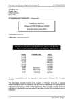
ISSUE HISTORY
DOCUMENT ISSUE: 8
PAGES
ISSUE
PAGES
ISSUE
PAGES
ISSUE
i to xvi
1-1 to 1-4
2-1 to 2-9
3-1 to 3-13
4-1 to 4-3
5-1 to 5-1
6-1 to 6-5
7-1 to 7-4
8-1 to 8-5
9-1 to 9-61
9
9
9
9
9
9
9
9
9
9
10-1 to 10-4
11-1 to 11-2
12-1 to 12-6
13-1 to 13-2
14-1 to 14-5
15-1 to 15-14
16-1 to 16-6
17-1 to 17-17
18-1 to 18-16
19-1 to 19-12
9
9
9
9
9
9
9
9
9
9
20-1 to 20-3
21-1
21-2 to 21-27
22-1
22-2 to 22-33
23-1 to 23-2
24-1 to 24-1
25-1 to 25-25
A-1 to A-10
B-1 to B-2
9
9
#1
9
#7
9
9
9
9
9
Sheets marked # contain manual inserts.
Source Type*
Sheets
Source Reference
1
ALL
FACIL_8.DOC
* Source Types: 1=Paper, 2=VAX File, 3=Microfilm, 4=Caltext Disc
5=DECmate disc, 6=Paper Insert, 7=MAC Disc
8=LIFESPAN,
9=Other - MAC Drawings in MAC/TPVOL/T400 Folder.
- MCE 0141 sheets included.
Changes for issue 8:
• Headers and footers have been updated.
• 9.5.1 Priority of one Hurry Call over another. Text amended.
667/EB/20200/000
Page iii
Issue 9
T400 Controller Facilities Manual
SUMMARY OF SECTIONS
1. INTRODUCTION
2. STAGES
3. PHASES
4. DEMANDS AND EXTENSIONS
5. CALL/CANCEL
6. HIGH SPEED VEHICLE DETECTION
7. ALL-RED DISPLAYS
8. PHASE DELAYS
9. MODES
10. STAGE MOVEMENT RESTRICTIONS
11. THE MASTER TIME CLOCK SYSTEM
12. THE EVENT TIMETABLE
13. LINKING
14. ALTERNATIVE SIGNAL SEQUENCES AND FLASHING SIGNALS
15. INPUTS AND OUTPUTS
16. MANUAL PANEL
17. PELICAN/PEDESTRIAN CONTROLLER
18. EQUIPMENT
19. ORIGINAL LAMP MONITORING UNIT
20. SPECIAL CONDITIONING
21. EXAMPLE OF AN INTERSECTION
22. EXAMPLE OF AN INTERSECTION ROAD TRAFFIC & LIGHT RAIL VEHICLES
23. MOVA (MICROPROCESSOR OPTIMISED VEHICLE ACTUATION)
24. GAS PLINTH
25. ANCILLARY PROCESSOR (INTEGRAL OTU/LMU/RLM)
APPENDIX A) SUPPLYING DC POWER FOR VEHICLE DETECTORS
APPENDIX B) 50-0-50 VOLT CONTROLLER
667/EB/20200/000
Page iv
Issue 9
T400 Controller Facilities Manual
CONTENTS
1. INTRODUCTION ................................................................................................ 1-1
1.1 GLOSSARY OF TERMS .................................................................................. 1-2
1.2 RELATED DOCUMENTS ................................................................................. 1-3
2. STAGES ............................................................................................................. 2-1
2.1 FACILITIES ...................................................................................................... 2-1
2.2 ALLOCATION OF PHASES ............................................................................. 2-1
2.3 STAGES ACTIVE ............................................................................................. 2-1
2.4 INTERSTAGE PERIOD .................................................................................... 2-1
2.5 STAGE CHANGE ALGORITHM ....................................................................... 2-1
2.5.1 Effects of Modes other than V.A. on Stage Change Algorithm............... 2-3
2.5.2 Usage of Stage Movement Restriction Tables ....................................... 2-4
2.6 PARALLEL STAGE STREAMING .................................................................... 2-4
2.6.1 General .................................................................................................. 2-4
2.6.2 Stage Streams........................................................................................ 2-4
2.6.3 Mode Selection....................................................................................... 2-5
2.6.4 Mode Operation...................................................................................... 2-6
2.6.5 Window Timers ...................................................................................... 2-8
2.6.6 Extend all Red (Hold Intergreen)............................................................ 2-8
2.6.7 LMU Supplementary Intergreen Extensions........................................... 2-8
2.6.8 LMU Maximum All Red ........................................................................... 2-9
2.6.9 SDE/SA .................................................................................................. 2-9
2.6.10 Arterial Reversion................................................................................. 2-9
3. PHASES ............................................................................................................. 3-1
3.1 FACILITIES ...................................................................................................... 3-1
3.2 TYPES OF PHASES ........................................................................................ 3-1
3.2.1 Traffic Phase .......................................................................................... 3-1
3.2.2 Pedestrian Phase ................................................................................... 3-2
3.2.3 Green Arrow Phase ................................................................................ 3-3
3.2.4 Dummy Phase ........................................................................................ 3-4
3.2.5 Switched Sign Phase ............................................................................. 3-4
3.3 CONFLICTING PHASES.................................................................................. 3-5
3.4 OPPOSING PHASES ....................................................................................... 3-5
3.5 TIMING PERIODS ............................................................................................ 3-6
3.5.1 Minimum Green (MIN) ............................................................................ 3-6
3.5.2 Green Extension (EXT) .......................................................................... 3-6
3.5.3 Maximum Green (MAX,MBX,MCX,MDX)................................................ 3-7
3.5.4 Pedestrian Blackout/Flashing Green (PBT) ........................................... 3-7
3.5.5 Intergreen (IGN) ..................................................................................... 3-7
3.5.6 Starting Intergreen (IGS) ........................................................................ 3-8
3.5.7 Conditioning Timers (PIR) ...................................................................... 3-8
3.5.8 Limit Green Watchdog (Facility constructed in Special Conditioning
for Export Only). ................................................................................ 3-9
3.6 HANDSET RANGE LIMITS AND THRESHOLD VALUES................................ 3-9
667/EB/20200/000
Page v
Issue 9
T400 Controller Facilities Manual
3.6.1 Minimum Green Thresholds ................................................................. 3-10
3.6.2 Intergreen Thresholds .......................................................................... 3-10
3.7 CONDITIONS OF APPEARANCE.................................................................. 3-10
3.7.1 Appearance Type 0 .............................................................................. 3-10
3.7.2 Appearance Type 1 .............................................................................. 3-10
3.7.3 Appearance Type 2 .............................................................................. 3-11
3.7.4 Appearance Type 3 .............................................................................. 3-11
3.7.5 Window Timers Parallel Stage Streaming Facilities ............................ 3-12
3.8 FIXED PHASES.............................................................................................. 3-12
3.9 NON-FIXED PHASES .................................................................................... 3-12
3.10 CONDITIONS OF TERMINATION ............................................................... 3-13
3.10.1 Termination Type 0 ............................................................................ 3-13
3.10.2 Termination Type 1 ............................................................................ 3-13
3.10.3 Termination Type 2 ............................................................................ 3-13
3.11 EARLY TERMINATION OF PHASES........................................................... 3-13
4. DEMANDS AND EXTENSIONS ......................................................................... 4-1
4.1 GENERAL DESCRIPTION ............................................................................... 4-1
4.2 TYPES OF DEMANDS ..................................................................................... 4-1
4.2.1 Latched................................................................................................... 4-1
4.2.2 Unlatched ............................................................................................... 4-1
4.3 ORIGINS OF DEMANDS AND EXTENSIONS ................................................. 4-1
4.3.1 On-Street Detection Equipment ............................................................. 4-1
4.3.2 Pedestrian Push-Buttons........................................................................ 4-1
4.3.3 Revertive Demands................................................................................ 4-2
4.3.4 UTC Demand Bits................................................................................... 4-2
4.3.5 Conditions Occurring.............................................................................. 4-2
4.3.6 Repeat Pulses ........................................................................................ 4-2
4.3.7 SDE/SA .................................................................................................. 4-2
4.3.8 Handset .................................................................................................. 4-2
4.4 OPERATION DURING CERTAIN MODES....................................................... 4-3
4.4.1 Manual, Fixed Time and Start Up Mode................................................. 4-3
4.4.2 UTC ........................................................................................................ 4-3
4.4.3 Mode ...................................................................................................... 4-3
4.4.4 Disabling Modes..................................................................................... 4-3
5. CALL/CANCEL ................................................................................................... 5-1
5.1 GENERAL ........................................................................................................ 5-1
5.2 CALL/CANCEL - METHODS OF USE.............................................................. 5-1
6. HIGH SPEED VEHICLE DETECTION................................................................ 6-1
6.1 SPEED DISCRIMINATION EQUIPMENT (SDE) .............................................. 6-1
6.1.1 Double SDE............................................................................................ 6-1
6.1.2 Triple SDE.............................................................................................. 6-1
6.1.3 SDE Extension Inhibit............................................................................. 6-2
6.2 SPEED ASSESSMENT (SA) ............................................................................ 6-2
6.3 ASSESSORS AVAILABLE ............................................................................... 6-2
6.4 EXTRA CLEARANCE PERIODS...................................................................... 6-2
667/EB/20200/000
Page vi
Issue 9
T400 Controller Facilities Manual
6.5 SDE/SA PARALLEL STAGE STREAMING FACILITIES .................................. 6-3
6.6 SDE/SA ON GREEN ARROWS ....................................................................... 6-3
6.7 COMMON APPROACH LANES ....................................................................... 6-3
6.8 OTHER LOOP SPACINGS............................................................................... 6-4
6.9 EQUIPMENT .................................................................................................... 6-4
6.10 EXAMPLE....................................................................................................... 6-4
6.11 HIGH SPEED DETECTORS WITH CALL CANCEL....................................... 6-4
7. ALL-RED DISPLAYS .......................................................................................... 7-1
7.1 ALL-RED STAGE ............................................................................................. 7-1
7.2 RED EXTENSION DURING INTERGREEN ..................................................... 7-2
7.2.1 Independent Intergreens ........................................................................ 7-3
7.2.2 Extend All Red (Hold I/G) Parallel Stage Streaming Facilities ............... 7-3
8. PHASE DELAYS ................................................................................................ 8-1
8.1 GENERAL DESCRIPTION ............................................................................... 8-1
8.2 PHASES LOSING RIGHT-OF-WAY................................................................. 8-1
8.3 PHASES GAINING RIGHT-OF-WAY ............................................................... 8-3
8.4 DELAY TIMER.................................................................................................. 8-3
8.5 PHASE DELAY HANDSET COMMANDS......................................................... 8-4
8.6 EFFECT OF RED EXTENSIONS AND SDE/SA............................................... 8-4
9. MODES .............................................................................................................. 9-1
9.1 START UP MODE ............................................................................................ 9-2
9.1.1 Normal Start-up Sequence ..................................................................... 9-2
9.1.2 Optional Start-Up Sequence .................................................................. 9-3
9.1.3 Start Up Parallel Stage Streaming Facilities .......................................... 9-3
9.2 PART TIME MODE........................................................................................... 9-5
9.3 URBAN TRAFFIC CONTROL (UTC) MODE .................................................... 9-6
9.3.1 Method of Plan Introduction ................................................................... 9-6
9.3.2 Summary of Control and Reply Bits ....................................................... 9-7
9.3.3 Control Bits............................................................................................. 9-8
9.3.4 Reply Bits ............................................................................................. 9-11
9.3.5 Special UTC Requirements.................................................................. 9-15
9.3.6 OTU Links ............................................................................................ 9-15
9.3.7 Methods of Control ............................................................................... 9-16
9.3.8 UTC Mode Conditions .......................................................................... 9-16
9.3.9 Outstation Transmission Units (OTU) .................................................. 9-17
9.3.10 The Effects of U.T.C. Control Bits on C.L.F. and Master Time
Clock ............................................................................................... 9-17
9.3.11 UTC Parallel Stage Streaming Facilities ............................................ 9-18
9.4 PRIORITY AND EMERGENCY VEHICLE MODE .......................................... 9-19
9.4.1 Definitions ............................................................................................ 9-19
9.4.2 Operational Description........................................................................ 9-21
9.4.3 Basic Facilities ..................................................................................... 9-26
9.4.4 Visual Indications ................................................................................. 9-29
9.4.5 Interfaces.............................................................................................. 9-29
9.4.6 Use of Priority Mode for Control in Light Rail Transit Systems ............ 9-30
667/EB/20200/000
Page vii
Issue 9
T400 Controller Facilities Manual
9.5 HURRY CALL MODE ..................................................................................... 9-33
9.5.1 Priority of One Hurry Call Over Another............................................... 9-35
9.5.2 Hurry Call Parallel Stage Streaming Facilities ..................................... 9-35
9.5.3 Control From A Remote Pushbutton .................................................... 9-36
9.5.4 Control From A Queue Detector........................................................... 9-36
9.5.5 Timings Range ..................................................................................... 9-36
9.6 SELECTED MANUAL CONTROL MODE....................................................... 9-37
9.6.1 Manual Mode........................................................................................ 9-37
9.6.2 Allocation Of Stages To Push-buttons ................................................. 9-37
9.6.3 Manual Mode Enable/Disable Facility .................................................. 9-38
9.6.4 Manual Control Parallel Stage Streaming Facilities............................. 9-38
9.6.5 Dim Override facility ............................................................................. 9-38
9.7 MANUAL STEP-ON MODE ............................................................................ 9-39
9.7.1 Manual Disable Switch (Police)............................................................ 9-39
9.7.2 Manual Step-on Mode Parallel Stage Streaming Facilities .................. 9-40
9.8 SELECTED FIXED TIME, CLF OR V.A. MODE ............................................. 9-41
9.9 CABLELESS LINKING FACILITY (CLF) MODE............................................. 9-41
9.9.1 Example Of Simple Linked Installation................................................. 9-43
9.9.2 Offset Timing ........................................................................................ 9-43
9.9.3 Different Plans And Offsets .................................................................. 9-44
9.9.4 Plan And Group Organisation .............................................................. 9-44
9.9.5 Group Influences.................................................................................. 9-45
9.9.6 Examples Of Plans ............................................................................... 9-46
9.9.7 Influence Set Combinations ................................................................. 9-46
9.9.8 Alternative CLF System........................................................................ 9-48
9.9.9 CLF Parallel Stage Streaming Facilities............................................... 9-51
9.10 VEHICLE ACTUATED (VA) MODE .............................................................. 9-53
9.10.1 Arterial Reversion............................................................................... 9-54
9.10.2 Arterial Reversion Parallel Stage Streaming Facilities....................... 9-55
9.10.3 Parallel Stage Streaming Facility ....................................................... 9-55
9.11 FIXED TIME WORKING............................................................................... 9-56
9.11.1 Fixed Time Mode................................................................................ 9-56
9.11.2 Fixed Time to Current Maximums (VA Mode with Permanent
Demands and Extensions) ............................................................. 9-56
9.11.3 Fixed Time Parallel Stage Streaming Facilities.................................. 9-57
9.12 MODE PRIORITY ......................................................................................... 9-59
9.13 TIMER RELATIONSHIPS............................................................................. 9-61
10. STAGE MOVEMENT RESTRICTIONS .......................................................... 10-1
10.1 PROHIBITED MOVES.................................................................................. 10-2
10.2 ALTERNATIVE MOVES ............................................................................... 10-2
10.3 IGNORE MOVES.......................................................................................... 10-3
10.4 PERMITTED MOVES ................................................................................... 10-3
10.5 PREVENTED STAGES/PHASES ................................................................. 10-4
11. THE MASTER TIME CLOCK SYSTEM .......................................................... 11-1
11.1 INTRODUCTION .......................................................................................... 11-1
11.2 REAL TIME CLOCK (RTC)........................................................................... 11-1
667/EB/20200/000
Page viii
Issue 9
T400 Controller Facilities Manual
11.3 TIMETABLE RESOLUTION ......................................................................... 11-2
11.4 BRITISH SUMMER TIME CHANGES........................................................... 11-2
11.5 MINUTE PULSE ........................................................................................... 11-2
12. THE EVENT TIMETABLE............................................................................... 12-1
12.1 PLAN CHANGE/EVENT TIMETABLE .......................................................... 12-1
12.2 CABLELESS LINK PLANS ........................................................................... 12-1
12.2.1 Synchronisation of Cableless Linking Equipment .............................. 12-2
12.3 SWITCH FUNCTION SETTING ................................................................... 12-2
12.3.1 Event Switch Default States ............................................................... 12-5
12.4 PARAMETERS ............................................................................................. 12-5
13. LINKING ......................................................................................................... 13-1
13.1 PELICAN CONTROLLER............................................................................. 13-1
13.2 REPEAT PULSES ........................................................................................ 13-2
13.3 OTU LINKING............................................................................................... 13-2
14. ALTERNATIVE SIGNAL SEQUENCES AND FLASHING SIGNALS .............. 14-1
14.1 ALTERNATIVE SIGNAL SEQUENCES........................................................ 14-1
14.2 ALTERNATIVE START-UP SEQUENCES ................................................... 14-2
14.3 FLASHING SIGNALS ................................................................................... 14-3
14.3.1 Variable Flashing Signals .................................................................. 14-3
14.4 EXPORT SIGNAL SEQUENCES ................................................................. 14-4
15. INPUTS AND OUTPUTS................................................................................ 15-1
15.1 INPUTS (I/P)................................................................................................. 15-1
15.2 OUTPUTS (O/P)........................................................................................... 15-1
15.3 LOGIC CONDITIONS................................................................................... 15-1
15.4 PORTS ......................................................................................................... 15-1
15.5 PROVISION OF I/O ON EXPANSION I/O, MAIN PROCESSOR AND
SDE/SA BOARDS...................................................................................... 15-2
15.6 INTERFACING ............................................................................................. 15-2
15.6.1 Cable Assemblies............................................................................... 15-3
15.6.2 Extended System Bus ........................................................................ 15-3
15.7 PORT ALLOCATION.................................................................................... 15-4
15.8 ‘DET’ HANDSET COMMAND ..................................................................... 15-11
15.9 DETECTOR FAULT MONITORING (DFM) ................................................ 15-12
15.9.1 DFM Timing...................................................................................... 15-13
15.9.2 Switched DFM .................................................................................. 15-14
15.9.3 Cabinet Alarm From Special Conditioning ....................................... 15-14
15.9.4 Fixed I/O for specific contracts......................................................... 15-14
16. MANUAL PANEL ............................................................................................ 16-1
16.1 STANDARD FACILITIES (Intersection Controller) ....................................... 16-1
16.1.1 Stage Selection Push-Buttons............................................................ 16-1
16.1.2 Mode Select Pushbuttons .................................................................. 16-1
16.1.3 Signals OFF/ON Switch ..................................................................... 16-1
667/EB/20200/000
Page ix
Issue 9
T400 Controller Facilities Manual
16.1.4 SW1, SW2 and SW3 Pushbuttons..................................................... 16-1
16.1.5 Lamp Dim Override Switch (If Configured)......................................... 16-1
16.1.6 DFM Reset Push-button (If Configured)............................................. 16-2
16.1.7 Lamp Test Push-button ...................................................................... 16-2
16.1.8 Manual Button Indicators.................................................................... 16-2
16.1.9 Awaiting Command Indicator.............................................................. 16-2
16.1.10 Prohibited Move Indicator ................................................................ 16-2
16.1.11 Hurry Call Active Indicator................................................................ 16-2
16.1.12 Higher Priority (UTC) Active Indicator .............................................. 16-2
16.1.13 Spare Indicators ............................................................................... 16-2
16.2 HONG KONG INTERNAL MANUAL PANEL ................................................ 16-3
16.2.1 Signals OFF/ON Switch ..................................................................... 16-3
16.2.2 SW1, SW2, SW3 Pushbuttons........................................................... 16-3
16.2.3 Lamp Dim Override switch ................................................................. 16-3
16.2.4 Spare Indicators ................................................................................. 16-3
16.3 PELICAN MANUAL PANEL.......................................................................... 16-4
16.4 EXTRA FACILITIES...................................................................................... 16-4
16.4.1 Basic Manual Panel............................................................................ 16-4
16.4.2 Fixings for BT Terminations ............................................................... 16-4
17. PELICAN/PEDESTRIAN CONTROLLER ....................................................... 17-1
17.1 GENERAL .................................................................................................... 17-1
17.1.1 Fixed Vehicle Period Mode ................................................................ 17-1
17.1.2 Pelican VA Mode................................................................................ 17-1
17.1.3 Short Vehicle Green via UTC............................................................. 17-2
17.2 PELICAN/PEDESTRIAN TIMINGS............................................................... 17-2
17.3 MANUAL PANEL FACILITIES ...................................................................... 17-3
17.3.1 Select VA/FVP.................................................................................... 17-3
17.3.2 Continuous Ped. Demand .................................................................. 17-3
17.3.3 Continuous Vehicle Extension............................................................ 17-3
17.3.4 DFM Reset ......................................................................................... 17-3
17.3.5 Auxiliary LEDs (AUX1/AUX2/AUX3) and Switches
(SW1/SW2/SW3)............................................................................ 17-3
17.4 HANDSET .................................................................................................... 17-4
17.4.1 Timings............................................................................................... 17-4
17.4.2 Speed Discrimination (SDE/SA) ......................................................... 17-4
17.5 I/O LINE ALLOCATION ................................................................................ 17-5
17.6 WAIT INDICATORS ..................................................................................... 17-6
17.7 AUDIO CONTROL AND MONITOR ............................................................. 17-6
17.8 GREEN CONFLICT FAULT ACTION ........................................................... 17-6
17.9 RED LAMP MONITORING ........................................................................... 17-6
17.10 DESCRIPTION OF I/O LINE FUNCTIONS................................................. 17-7
17.10.1 UTC Facilities (Control Bits)............................................................. 17-8
17.10.2 UTC Facilities (Reply Bits) ............................................................... 17-9
17.10.3 Local Link Facilities........................................................................ 17-10
17.10.4 Call/Cancel Function ...................................................................... 17-12
17.10.5 Puffin I/O Facilities ......................................................................... 17-12
17.11 TIMESWITCH FACILITIES....................................................................... 17-14
17.11.1 Switch Audio off.............................................................................. 17-14
667/EB/20200/000
Page x
Issue 9
T400 Controller Facilities Manual
17.11.2 Alternative Max. sets ...................................................................... 17-14
17.11.3 Switch to FVP mode ....................................................................... 17-14
17.11.4 Enhanced DFM .............................................................................. 17-14
17.12 CONDITIONING FACILITIES ................................................................... 17-14
17.12.1 Dual Level and Audible On/Off control........................................... 17-14
17.12.2 Real Time Clock Synchronisation. ................................................. 17-14
17.12.3 Special Detector checking.............................................................. 17-15
17.13 CLF FACILITIES....................................................................................... 17-15
17.14 CROSS INHIBIT LINKING (DUAL PELICAN)........................................... 17-15
18. EQUIPMENT .................................................................................................. 18-1
18.1 PHASE FACILITIES ..................................................................................... 18-1
18.2 MAIN CONTROLLER UNITS ....................................................................... 18-1
18.3 PED. AUDIBLE / TACTILE INDICATION (MCE0141 CONTROLLERS ONLY)
.................................................................................................................. 18-2
18.4 SWITCHED MAINS VOLTAGE PEDESTRIAN AUDIBLES (Export Only).... 18-2
18.5 DUAL LEVEL AUDIBLES ............................................................................. 18-3
18.6 DETECTOR RACKS AND DETECTORS ..................................................... 18-3
18.7 SIGNAL DIMMING........................................................................................ 18-4
18.7.1 Dimming by Time of Day .................................................................... 18-4
18.8 T400 FAILURE FLASHER UNIT .................................................................. 18-5
18.9 FUSES, LOADING, VOLTAGE AND FREQUENCY..................................... 18-5
18.10 CONTROLLER DOOR STAY FACILITIES ................................................. 18-5
18.11 INTERNAL ILLUMINATION........................................................................ 18-5
18.12 POWERING EXTERNALLY SITUATED D-DETECTORS WITH PSU
TYPE 667/1/20654/000 ............................................................................. 18-6
19. ORIGINAL LAMP MONITORING UNIT .......................................................... 19-1
19.1 LAMP MONITOR + OTU (NOT RED LAMP MONITORING) ........................ 19-3
19.2 RED LAMP MONITORING ........................................................................... 19-4
19.2.1 Effect of RLM on Intergreens and Phase delays................................ 19-7
19.3 L.M.U. PARALLEL STAGE STREAMING FACILITIES............................... 19-10
19.3.1 LMU Supplementary Intergreen Extensions..................................... 19-10
19.3.2 LMU Maximum All Red ..................................................................... 19-10
19.4 SET UP CONNECTIONS FOR RED LAMP MONITORING ....................... 19-11
19.4.1 Link Pin Connections ....................................................................... 19-11
19.4.2 Configuration Switch (SW1) ............................................................. 19-11
19.4.3 LMU Output Connections To Controller Inputs ................................ 19-11
19.4.4 Configuration Requirements............................................................. 19-12
20. SPECIAL CONDITIONING ............................................................................. 20-1
20.1 INTRODUCTION .......................................................................................... 20-1
20.2 SPECIAL CONDITIONING OPERATORS.................................................... 20-1
20.3 SPECIAL CONDITIONING EXAMPLES ....................................................... 20-1
20.4 READING CONTROLLER TIMERS ............................................................. 20-2
20.5 SPECIAL CONDITIONING WITH CONTROLLER CONFIGURING
SYSTEM .................................................................................................... 20-3
667/EB/20200/000
Page xi
Issue 9
T400 Controller Facilities Manual
21. EXAMPLE OF AN INTERSECTION ............................................................... 21-1
22. EXAMPLE OF AN INTERSECTION ROAD TRAFFIC & LIGHT RAIL
VEHICLES............................................................................................................ 22-1
23. MOVA (MICROPROCESSOR OPTIMISED VEHICLE ACTUATION)............. 23-1
23.1 INSTRUCTIONS FOR CONNECTING MOVA TO TRAFFIC
CONTROLLERS ........................................................................................ 23-1
24. GAS PLINTH .................................................................................................. 24-1
24.1 GENERAL DESCRIPTION ........................................................................... 24-1
25. ANCILLARY PROCESSOR (INTEGRAL OTU/LMU/RLM) ............................. 25-1
25.1 GENERAL DESCRIPTION ........................................................................... 25-1
25.1.1 FUNCTIONAL APPLICATIONS.......................................................... 25-1
25.1.2 PHYSICAL DESCRIPTION ................................................................ 25-4
25.1.3 ANCILLARY PROCESSOR PCB ELECTRONICS ............................. 25-4
25.2 ANCILLARY PROCESSOR CARD INSTALLATION .................................... 25-5
25.2.1 General .............................................................................................. 25-5
25.2.2 Configuring the Ancillary Processor PCB........................................... 25-5
25.2.3 Safety Warning................................................................................... 25-5
25.2.4 Cover.................................................................................................. 25-6
25.2.5 Configuring the Switches on the Ancillary Processor PCB ................ 25-6
25.2.6 Connectors and Cables...................................................................... 25-9
25.2.7 Effect of Incorrect Switch Settings on the Ancillary Processor PCB. 25-14
25.2.8 Fault Finding at the Outstation ......................................................... 25-15
25.2.9 Lithium battery.................................................................................. 25-15
25.2.10 Recommended Spares................................................................... 25-15
25.3 RLM GENERAL DESCRIPTION................................................................. 25-16
25.3.1 Background Information ................................................................... 25-16
25.3.2 Overview .......................................................................................... 25-16
25.4 ENHANCED RLM DETAILED DESCRIPTION ........................................... 25-17
25.4.1 Operation On First Red Lamp Fail ................................................... 25-17
25.4.2 Operation On Second Red Lamp Fail .............................................. 25-19
25.4.3 Operation With Free-Standing RLM Unit ......................................... 25-20
25.4.4 Support for Original RLM Facility ..................................................... 25-21
25.4.5 Configuration Data ........................................................................... 25-22
25.4.6 Configuration Considerations........................................................... 25-25
APPENDIX A) SUPPLYING DC POWER FOR VEHICLE DETECTORS ............... A-1
Appendix A.1) Using 24v 2A Internal Supply for Detectors .................................... A-2
Appendix A.2) Using 24v 2A Internal Supply - Cable limitations............................ A-3
Appendix A.3) Using 27.5v Additional Detector PSU ............................................. A-5
Appendix A.4) Using 27.5v Detector Supply - Cable Limitations............................ A-6
Appendix A.5) Cable Distances for SDE ................................................................ A-8
APPENDIX B) 50-0-50 VOLT CONTROLLER........................................................ B-1
667/EB/20200/000
Page xii
Issue 9
T400 Controller Facilities Manual
B.1 50-0-50 volt Controller ..................................................................................... B-1
B.2 Dual Solar Cell (Only Available on 50-0-50 Volt Controller) ............................ B-2
667/EB/20200/000
Page xiii
Issue 9
T400 Controller Facilities Manual
TABLE OF FIGURES
FIGURE 6.1 - SDE/SA LAYOUTS .......................................................................... 6-5
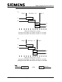
FIGURE 8.1 - DELAY PHASE LOSING RIGHT-OF-WAY...................................... 8-2
FIGURE 8.2 - DELAY PHASE GAINING RIGHT-OF-WAY .................................... 8-5
FIGURE 9.1 - START-UP SEQUENCE .................................................................. 9-4
FIGURE 9.2 - PRIORITY DEMAND ORDER........................................................ 9-32
FIGURE 9.3 - TWO DELAYS SET FOR ONE PRIORITY UNIT........................... 9-32
FIGURE 9.4 - POLICE MANUAL STEP-ON PANEL LAYOUT ............................. 9-40
FIGURE 9.5 - SIMPLE INTERSECTION WITH CLF ............................................ 9-42
FIGURE 9.6 - SIMPLE LINKED INSTALLATION ................................................. 9-43
FIGURE 9.7 - EXAMPLES OF INFLUENCE SET COMBINATIONS .................... 9-47
FIGURE 9.8 - EXAMPLE OF VA STAGE CHANGES........................................... 9-54
FIGURE 9.9 - GENERAL TIMERS ....................................................................... 9-61
FIGURE 9.10 - PHASE COMPENSATION........................................................... 9-61
FIGURE 15.1 - BLOCK DIAGRAM OF MAIN PROCESSOR BOARD.................. 15-5
FIGURE 15.2 - PCB POSITIONS AND LAYOUT OF PHASE DRIVER
RIBBON CABLES ...................................................................................... 15-6
FIGURE 15.3 - REAR VIEW OF PCB I/O CONNECTIONS (T400 LARGE
SHOWN).................................................................................................... 15-7
FIGURE 15.4 - TERMINAL BLOCKS IN SMALL CONTROLLER......................... 15-8
FIGURE 15.5 - TERMINAL BLOCKS IN LARGE CONTROLLER ........................ 15-9
FIGURE 15.6 - TERMINAL BLOCKS IN LARGE CONTROLLER (HONG
KONG) ..................................................................................................... 15-10
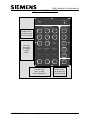
FIGURE 16.1 - MANUAL PANEL ......................................................................... 16-5
FIGURE 16.2 - INTERNAL MANUAL PANEL (HONG KONG) ............................. 16-6
FIGURE 17.1 - PELICAN MANUAL PANEL (STANDARD) ................................ 17-16
FIGURE 17.2 - PELICAN MANUAL PANEL (BASIC) ......................................... 17-17
FIGURE 18.1 - PEDESTRIAN AUDIBLE INDICATION (SIGNAL HEAD
MOUNTING) .............................................................................................. 18-7
FIGURE 18.2 - PEDESTRIAN AUDIBLE INDICATION (CONTROLLER
MOUNTING) .............................................................................................. 18-8
FIGURE 18.3 - PEDESTRIAN TACTILE INDICATION (SIGNAL HEAD
MOUNTING) .............................................................................................. 18-9
FIGURE 18.4 - PEDESTRIAN TACTILE INDICATION (CONTROLLER
MOUNTING) ............................................................................................ 18-10
FIGURE 18.5 - POSSIBLE PCB CONFIGURATIONS........................................ 18-11
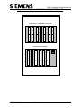
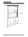
FIGURE 18.6 - FRONT VIEW OF THE TYPE 400 CONTROLLER (LARGE
O/C) ......................................................................................................... 18-12
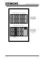
FIGURE 18.7 - FRONT VIEW OF THE TYPE 400 CONTROLLER (SMALL
O/C) ......................................................................................................... 18-13
FIGURE 18.8 - CONNECTING DUAL LEVEL AUDIBLES.................................. 18-14
FIGURE 18.9 - SINGLE SIDED ACCESS T400L ............................................... 18-15
FIGURE 19.1 - LAMP MONITOR OVERVIEW ..................................................... 19-2
FIGURE 19.2 - RED LAMP MONITORING .......................................................... 19-5
FIGURE 19.3 - LMU HOLD WITHOUT LOSING PHASE DELAY ........................ 19-8
FIGURE 19.4 - LMU HOLD WITH LOSING PHASE DELAY................................ 19-9
FIGURE 21.1 - CUSTOMER SPEC SHEET EXAMPLE ...................................... 21-2
FIGURE 21.2 - CUSTOMER SPEC SHEET EXAMPLE ...................................... 21-3
667/EB/20200/000
Page xiv
Issue 9
T400 Controller Facilities Manual
FIGURE 21.3 - CUSTOMER SPEC SHEET EXAMPLE ...................................... 21-4
FIGURE 21.4 - CUSTOMER SPEC SHEET EXAMPLE ...................................... 21-5
FIGURE 21.4A - CUSTOMER SPEC SHEET EXAMPLE..................................... 21-6
FIGURE 21.5 - CUSTOMER SPEC SHEET EXAMPLE ...................................... 21-7
FIGURE 21.6A - CUSTOMER SPEC SHEET EXAMPLE..................................... 21-8
FIGURE 21.6B - CUSTOMER SPEC SHEET EXAMPLE..................................... 21-9
FIGURE 21.7 - CUSTOMER SPEC SHEET EXAMPLE .................................... 21-10
FIGURE 21.8 - CUSTOMER SPEC SHEET EXAMPLE .................................... 21-11
FIGURE 21.8A - CUSTOMER SPEC SHEET EXAMPLE................................... 21-12
FIGURE 21.9 - CUSTOMER SPEC SHEET EXAMPLE .................................... 21-13
FIGURE 21.9A - CUSTOMER SPEC SHEET EXAMPLE................................... 21-14
FIGURE 21.9B - CUSTOMER SPEC SHEET EXAMPLE................................... 21-15
FIGURE 21.10 - CUSTOMER SPEC SHEET EXAMPLE ................................... 21-16
FIGURE 21.11 - CUSTOMER SPEC SHEET EXAMPLE ................................... 21-17
FIGURE 21.12 - CUSTOMER SPEC SHEET EXAMPLE ................................... 21-18
FIGURE 21.13 - CUSTOMER SPEC SHEET EXAMPLE ................................... 21-19
FIGURE 21.14 - CUSTOMER SPEC SHEET EXAMPLE ................................... 21-20
FIGURE 21.15 - CUSTOMER SPEC SHEET EXAMPLE ................................... 21-21
FIGURE 21.16 - CUSTOMER SPEC SHEET EXAMPLE ................................... 21-22
FIGURE 21.17 - CUSTOMER SPEC SHEET EXAMPLE ................................... 21-23
FIGURE 21.18 - CUSTOMER SPEC SHEET EXAMPLE ................................... 21-24
FIGURE 21.19 - CUSTOMER SPEC SHEET EXAMPLE ................................... 21-25
FIGURE 21.20 - CUSTOMER SPEC SHEET EXAMPLE ................................... 21-26
FIGURE 21.21 - CUSTOMER SPEC SHEET EXAMPLE ................................... 21-27
FIGURE 22.1 - CUSTOMER SPEC SHEET EXAMPLE ....................................... 22-2
FIGURE 22.2 - CUSTOMER SPEC SHEET EXAMPLE ....................................... 22-3
FIGURE 22.3 - CUSTOMER SPEC SHEET EXAMPLE ....................................... 22-4
FIGURE 22.4 - CUSTOMER SPEC SHEET EXAMPLE ....................................... 22-5
FIGURE 22.5 - CUSTOMER SPEC SHEET EXAMPLE ....................................... 22-6
FIGURE 22.6 - CUSTOMER SPEC SHEET EXAMPLE ....................................... 22-7
FIGURE 22.7 - CUSTOMER SPEC SHEET EXAMPLE ....................................... 22-8
FIGURE 22.8 - CUSTOMER SPEC SHEET EXAMPLE ....................................... 22-9
FIGURE 22.9 - CUSTOMER SPEC SHEET EXAMPLE ..................................... 22-10
FIGURE 22.10 - CUSTOMER SPEC SHEET EXAMPLE ................................... 22-11
FIGURE 22.11 - CUSTOMER SPEC SHEET EXAMPLE ................................... 22-12
FIGURE 22.12 - CUSTOMER SPEC SHEET EXAMPLE ................................... 22-13
FIGURE 22.13 - CUSTOMER SPEC SHEET EXAMPLE ................................... 22-14
FIGURE 22.14 - CUSTOMER SPEC SHEET EXAMPLE ................................... 22-15
FIGURE 22.15 - CUSTOMER SPEC SHEET EXAMPLE ................................... 22-16
FIGURE 22.16 - CUSTOMER SPEC SHEET EXAMPLE ................................... 22-17
FIGURE 22.17 - CUSTOMER SPEC SHEET EXAMPLE ................................... 22-18
FIGURE 22.18 - CUSTOMER SPEC SHEET EXAMPLE ................................... 22-19
FIGURE 22.19 - CUSTOMER SPEC SHEET EXAMPLE ................................... 22-20
FIGURE 22.20 - CUSTOMER SPEC SHEET EXAMPLE ................................... 22-21
FIGURE 22.21 - CUSTOMER SPEC SHEET EXAMPLE ................................... 22-22
FIGURE 22.22 - CUSTOMER SPEC SHEET EXAMPLE ................................... 22-23
FIGURE 22.23 - CUSTOMER SPEC SHEET EXAMPLE ................................... 22-24
FIGURE 22.24 - CUSTOMER SPEC SHEET EXAMPLE ................................... 22-25
FIGURE 22.25 - CUSTOMER SPEC SHEET EXAMPLE ................................... 22-26
667/EB/20200/000
Page xv
Issue 9
T400 Controller Facilities Manual
FIGURE 22.26 - CUSTOMER SPEC SHEET EXAMPLE ................................... 22-27
FIGURE 22.27 - CUSTOMER SPEC SHEET EXAMPLE ................................... 22-28
FIGURE 22.28 - CUSTOMER SPEC SHEET EXAMPLE ................................... 22-29
FIGURE 22.29 - CUSTOMER SPEC SHEET EXAMPLE ................................... 22-30
FIGURE 22.30 - CUSTOMER SPEC SHEET EXAMPLE ................................... 22-31
FIGURE 22.31 - CUSTOMER SPEC SHEET EXAMPLE ................................... 22-32
FIGURE 22.32 - CUSTOMER SPEC SHEET EXAMPLE ................................... 22-33
FIGURE 25.1 - ANCILLARY PROCESSOR PCB LAYOUT.................................. 25-8
FIGURE 25.2 - LMU INPUT CONNECTOR........................................................ 25-10
667/EB/20200/000
Page xvi
Issue 9
T400 Controller Facilities Manual
1. INTRODUCTION
This manual refers to the facilities available in the Type 400 Controller using firmware
PB321 and PB322. For precise details of facilities supported by earlier versions of
firmware see 667/SU/20200/000. This document is included in the General Handbook.
The controller conforms to the UK Department of Transport Specification MCE 0141,
but also incorporates extra facilities.
The operation of the controller is phase oriented. Timings and demands are associated
with phases and the control philosophy is designed to give right-of-way to phases in an
optimum manner.
It is necessary to group phases into stages for Manual Control, operation in Urban
Traffic Control Schemes and in Cableless Linking Schemes.
The grouping of phases into stages is conditioned by the traffic requirements and safety
constraints.
Requests for ROW are received by the controller from:
(a)
(b)
(c)
(d)
(e)
‘On-street’ detection equipment and pedestrian pushbuttons
the UTC computer
the Cableless Linking Facility
manual inputs
special requests, e.g. hurry calls
The controller then orders the appearance of phases in accordance with the controller
strategy, the current mode operative and the demand requests for ROW. The
controller will always change stages cyclically.
667/EB/20200/000
Page 1-1
Issue 9
T400 Controller Facilities Manual
1.1 GLOSSARY OF TERMS
Abbreviations
AC
CET
CLF
CLU
CMOS
CPU
CRC
CVT
DC
DFM
ELCB
EMxxxxx
EPROM
FT
FVP
GP
GR
I/G
I/O
I/P
KOP
LCD
LED
LMU
LRT
LRV
LSTTL
mA
MC
MOVA
mS
MTC
MTCS
NLT
NRT
OMCU
OMU
OTU
PCB
PPM
PROM
PSU
RAM
RCD
RFL
667/EB/20200/000
Alternating Current
Cable Earth Terminal
Cableless Linking Facility
Cableless Linking Unit
Complementary Metal Oxide Silicon
Central Processing Unit
Cyclic Redundancy Code
Constant Voltage Transformer
Direct Current
Detector Fault Monitor
Earth Leakage Circuit Breaker
Controller Identity Number (Electromatic)
Erasable Programmable Read Only Memory
Fixed Time
Fixed Vehicle Period (Pelican mode)
General Purpose
“GR” Electronics Ltd.
Intergreen
Input/Output
Input
Kit of Parts
Liquid Crystal Display
Light Emitting Diode
Lamp Monitor Unit
Light Rail Transit
Light Rail Vehicle
Low Power Schottky Transistor Transistor Logic
Milliamps
Manual Control
Microprocessor Optimised Vehicle Actuation
MilliSeconds
Master Time Clock
Master Time Clock System
No Left Turn
No Right Turn
Outstation Monitor and Control Unit
Outstation Monitor Unit
Outstation Transmission Unit
Printed Circuit Board
Parts Per Million
Programmable Read Only Memory
Power Supply Unit
Random Access Memory
Residual Current Device
Reset Fault Log (Handset Command)
Page 1-2
Issue 9
T400 Controller Facilities Manual
RLMU
RMS
ROW
RTC
SA
SDE
SIE
ST
STS
SVD
SWG
TCSU
UTC
VA
Red Lamp Monitor Unit
Root Mean Square
Right Of Way
Real Time Clock
Speed Assessment
Speed Discrimination Equipment
Supplementary Intergreen Extensions
Self Tuning
Site to Scale Drawing
Selective Vehicle Detector
Standard Wire Gauge
Traffic Control Systems Unit
Urban Traffic Control
Vehicle Actuated
1.2 RELATED DOCUMENTS
667/HH/20200/000
T400 CONTROLLER HANDSET COMMAND LIST
This handbook details the following:
(a)
Data entry, Display and command formats
(b)
The controller data which can be accessed via the handset and the handset
commands necessary to access the items.
(c)
Operational aspects of the intelligent terminal software which allows an
EPSON HX20 to act as an intelligent terminal for use with a T400.
(d)
Operational aspects of the intelligent terminal software which allows an IBM
PC compatible Laptop Personal Computer to act as an intelligent terminal for
use with a T400.
667/HD/20200/000
INTERSECTION CONFIGURATOR 003 USERS HANDBOOK
This handbook details the following:
(a)
The hardware requirements for a configuring system (the configurator is
Siemens software running on an IBM PC compatible computer).
(b)
How to use the configuring system to enter data from the completed customer
specification sheets into the computer and produce the programmed EPROMs
required to configure the T400 controller.
This includes the writing of special conditioning and details on error messages which
may be produced during the processing if data entered.
667/EB/20200/000
Page 1-3
Issue 9
T400 Controller Facilities Manual
667/HA/20200/000
MAINTENANCE HANDBOOK FOR THE T400 CONTROLLER
This handbook details the following:
(a)
Safety procedures when working on the T400 traffic controller and its ancillary
equipment.
(b)
The use of the handset/terminal for maintenance purpose.
(c)
Routine maintenance/inspection procedures.
(d)
Fault finding procedures.
(e)
Procedures for replacing PCBs.
(f)
Clarification of specific controller functions.
(g)
PCB histories and retrospective modifications since initial design.
(h)
The last section of the handbook contains a basic overview of the controller
hardware at module level with a block diagram representation of the hardware.
667/EB/20200/000
Page 1-4
Issue 9
T400 Controller Facilities Manual
2. STAGES
2.1 FACILITIES
There are up to 16 stages (0 to 15) available for use.
Stage 0 is normally used as a manual all-red facility. It may be used as a traffic stage.
Stage 1 normally is the start-up stage and must not be deleted.
Some stages may appear in some modes but not others. However, it may be possible to
be in a stage not in the current mode if a change of mode occurs. If this happens then
the stage will respond to current stage change conditions after all minimum greens for
the phases in the stage have timed off.
2.2 ALLOCATION OF PHASES
The available phases are allocated to the stages in any combination subject to the
method of control, the traffic requirements and safety considerations. Figure 21.2 and
Figure 21.5 illustrate an example of allocating phases to stages.
2.3 STAGES ACTIVE
A stage is considered active when all fixed phases (see Sections 3.7.1 & 3.8) that are
allocated to the stage are at green and all phases (fixed or non-fixed) that are not
allocated to the stage are at red.
A stage is considered to be terminating when:
The first phase which has had ROW (i.e. been at green) during the stage, loses right of
way.
2.4 INTERSTAGE PERIOD
The interstage period is the time between one stage terminating and another stage
becoming active.
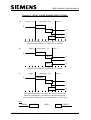
2.5 STAGE CHANGE ALGORITHM
In all modes the controller monitors the following all demands (for both phases and
stages), extensions and maximum green timers every 200ms. These are monitored in
order to check to see if it is possible to move to a new stage, and serve new demands.
In order to select the next stage (SUGGESTED STAGE) the controller goes through
the following decision-making process.
667/EB/20200/000
Page 2-1
Issue 9
T400 Controller Facilities Manual
Firstly, the controller sets the “suggested stage” as the current stage and the number of
new “phases & stages to get right of way” to zero ‘0’.
These two items will then be updated as the controller goes though its decision-making
process.
The following process is performed for each stage in cyclic order starting at current
stage +1.
1.
Are any of the phases in the stage or the stage itself, prevented and/or deleted?
If NO, proceed to next step.
If YES, (prevented and/or deleted) try next stage in cyclic order (starting at
step 1).
2.
Are there demands for phases in this stage or for the stage itself.
If YES, proceed to next step.
If NO, (i.e. phases/stage not demanded) try next stage in cyclic order (starting
at step 1).
3.
Can the current stage be terminated?
i.e. will all phases which have extensions and for which the maximum green
timer has not expired keep right of way in this stage (if selected as the
“Suggested Stage”.)
If YES, proceed to next step.
If NO, add the demanded phases in this stage (or the stage itself if stage is
demanded) to “Phases & Stages to Get right of way” (for checking later). Then
try next stage in cyclic order (starting at Step 1).
4.
Will all demanded phases which appear in previously checked stages and any
specifically demanded stages previously checked (i.e. “Phases & Stages to Get
right of way”) get right of way, be serviced by this stage?
(N.B. Obviously if a previously checked stage is itself specifically demanded,
no other stage can satisfy the demand and the answer to above question will be
NO. Stage demands are normally only inserted from special conditioning or
Modes of operation where specific stages are requested, i.e. CLF, UTC, Hurry
Call, Fixed Time, Manual or Manual Step-On.)
If YES, proceed to next step.
667/EB/20200/000
Page 2-2
Issue 9
T400 Controller Facilities Manual
If NO, add the demand phases in this stage (or the stage itself if stage is
demanded) to “Phases & stages to Get right of way”. Then try next stage in
cyclic order (starting at Step 1).
5.
Will more demanded phases be serviced by this stage than in previously
“Suggested Stage”?
If YES, set “Suggested Stage” equal to this stage.
If NO, add the demanded phases in this stage (or the stage itself if stage is
demanded) to “Phases & Stages to Get right of way”. Then try next stage in
cyclic order (starting at Step 1).
At the end of the decision-making process the “Suggested Stage” will either be
a new stage other than the current stage, or it will have remained as the current
stage.
If the suggested stage is other than the current stage, the controller then checks
the “Stage movement restriction” table appropriate to the mode, to see if it can
make the move, see below:
If the move from the current stage to the “Suggested Stage” is prohibited, the
controller will stay in the current stage until the decision-making process comes
up with a different “Suggested Stage” to move to.
If the move from the current stage to “Suggested Stage” is an Ignore move, the
controller will immediately return to the decision-making process, it will
remove from the equation the demanded phases which would have been served
by the previously “Suggested Stage” (so that process does not come up with
same “Suggested Stage” again), and then it will start again searching for a
stage to move to.
If the move from the current stage to the “Suggested Stage” has an alternative
stage move specified, the controller will move to the alternative stage and then
restart the decision-making process.
If the move from the current stage to the “Suggested Stage” is unrestricted, the
controller will move to the “Suggested Stage” and then restart the decisionmaking process.
2.5.1 Effects of Modes other than V.A. on Stage Change Algorithm
In V.A. mode, the stage change algorithm is allowed to suggest a stage based on the
influences current at the time without any manipulating of those influences.
667/EB/20200/000
Page 2-3
Issue 9
T400 Controller Facilities Manual
However, in other modes, namely CLF, UTC, Fixed Time, Priority, Part-Time, Manual
and Manual Step-On, the modes influence the outcome of the stage change algorithm.
This can be done by:
a) applying stage/phase prevents,
b) masking out phase demand,
c) inserting stage demands,
d) masking out extensions, i.e. causing them to be ignored,
e) Suspending maximum green times.
Thus for above-mentioned modes, specific stages may be requested, and the controller
forced to serve them when required.
2.5.2 Usage of Stage Movement Restriction Tables
The controller will always use the stage movement restriction table, applicable to the
mode in which it is operating when it initiates the stage change.
EXAMPLE
If a priority demand invokes a stage change, the controller will be in priority mode due
to the priority demand and will use the stage change restrictions table applicable to
priority mode.
However, if the controller has already decided to make a stage change in the VA mode
and a priority demand is received, the controller will continue to make the VA move
although the mode will have changed. The controller will then only use the stage
movement restriction table applicable to priority mode if it makes any subsequent
moves whilst still in priority mode.
2.6 PARALLEL STAGE STREAMING
2.6.1 General
Parallel Stage Streaming will provide independant control of up to 4 separate
intersections, later referred to as Streams, from one controller, i.e. the four
intersections may be considered as being controlled by separate controllers with the
exception of working in Manual mode, Part Time mode (see section 2.6.3), linked
fixed time and manual step on (see section 2.6.4).
This facility would normally be used if there are to be no cross-stream Phase Conflicts.
However, cross-stream Phase Conflicts and cross-stream Linking can be covered by
using either cross-stream Phase Intergreen or Special Conditioning Software.
2.6.2 Stage Streams
The controller will support up to 4 streams (numbered 0 to 3). Each stream may
contain any number of stages but no stage may appear in more than one stream and the
total number of stages for all streams must not exceed 16.
667/EB/20200/000
Page 2-4
Issue 9
T400 Controller Facilities Manual
All stages contained within a stream must be numbered consecutively starting at Stage
0 for Stream 0.
If a stream requires an all red condition then a separate all red stage must be provided
for that stream. No phase may appear in more than one stream.
2.6.3 Mode Selection
Each stream will independently run the highest priority mode for which a request
exists, except in the case of Manual and Part Time modes. (See also section 9.12).
Manual mode will be operated on all streams simultaneously and will be operative only
if Manual has been selected from the Manual Panel and no higher priority mode is
running on any stream. If Manual Mode has been selected and one or more streams
runs a higher priority mode, then Manual Mode will not be operational on any stream.
Any stream not running a higher than Manual priority mode will run a lower than
Manual priority mode.
Part Time Mode will always be placed in the top priority position and, when requested,
will be implemented on all streams simultaneously.
Each mode, with the exception of Manual and Part Time, may be configured so that it
is disabled on an individual stream. Manual and Part Time may be disabled but would
be disabled on all streams simultaneously. The modes may be disabled as a standard
configuration item but may also be enabled or disabled on a per stream basis via
Special Conditioning.
Forms IX & IXa allow for modes to be disabled permanently, and operation of certain
mode select buttons to be made inoperative permanently.
However, some situations do not require the above-mentioned items deleted on a
permanent basis, rather only under special conditions.
For example, on a two stream controller, if VA was not required on Stream 1 but was
required on Stream 2, the mode could be permanently disabled for Stream 1. However,
the selected VA position of the mode select buttons could not be made permanently
non-operative, and similarly neither could the ‘Selected Fixed Time/VA’ mode on form
IXa. As Selected Fixed Time will be required on Stream 1 (where VA is not required)
and both selected VA and Selected Fixed Time may be required on Stream 2. In this
instance, Special Conditioning is required to disable the ‘Selected Fixed Time/VA’
mode on Stream 1 when the VA mode select button is pressed (see also Section 4.4.4).
667/EB/20200/000
Page 2-5
Issue 9
T400 Controller Facilities Manual
2.6.4 Mode Operation
(See also section 9.)
2.6.4(a) Fixed Time
Each stream will have its own fixed sequence of stages and will move around it
independently of the other streams. Alternatively the streams can be linked, allowing
groups of stages to run together, i.e. Linked Fixed Time.
2.6.4(b) VA
Each stream will move around its own stages according to its own on street demands
and extensions independent of any other streams.
2.6.4(c) CLF
The controller has up to 8 plans. Each plan can run up to 16 groups. Each group when
active can operate up to 4 influences simultaneously,1 influence for each stream. There
is an influence set for each plan where an influence set consists of 4 influences for each
of the 16 groups (Combinations A, B, C and D). In general, Influence Set Combination
‘A’ would be used for Stream 0, Influence Set Combination ‘B’ for Stream 1, etc.
In this way it is possible on introduction of a group to operate different influences at
the same time on difference streams.
If it is required that, during a given group timing, a stream is not required to change
influence, then this stream’s influence should be set to Group Influence number 7
followed by the related stage number, i.e. the number of any stage contained within the
stream upon which the influence acts. (See sub-section 9.9.7, Figure 9.7).
Only one plan can be in operation on the controller at once while in CLF. CLF can run
on all streams at once or on some streams with the remainder running higher priority
modes. If CLF is disabled on a stream then that stream will run the next lower priority
mode.
For further description of CLF mode see section 9.9.
2.6.4(d) Manual Control
The Manual Stage Buttons are programmed so that each of the 7 buttons can select:
a)
a combination of stages, one from each stream, that will run
simultaneously.
b)
one stage from any one stream
The all red button can be programmed to select:
a)
an all red condition on all streams
b)
an all red condition on any one stream - it would normally be necessary
to programme other buttons for all red conditions on any other streams.
667/EB/20200/000
Page 2-6
Issue 9
T400 Controller Facilities Manual
The Awaiting New Command lamp will only illuminate when all phase minimums on
all streams have expired and consequently allow further moves to be made using the
Manual Buttons.
A change is accepted as valid even if only one of the stage streams changes.
The Manual Panel indicators illuminate when the stage that is configured to the
corresponding button is active.
For parallel Stage Streams the buttons can be configured to call combinations of stages
in the individual streams and the LEDs illuminate when the combinations configured to
the corresponding buttons are active. The indicators illuminate in VA and fixed time
mode as well as manual mode and irrespective of whether the handset is plugged in.
Manual Step-On:If fitted, the Controller will step on to the next stage, or combination of stages, on the
operation of a pushbutton. See also section 9.7.
2.6.4(e) Hurry Call
2 Hurry Call units are available, numbered 0 and 1, and they may be allocated to any
stage on any stream.
If they are both allocated to different stages but in the same stream, they will be
actioned on the basis of Hurry Call 0 being of higher priority than Hurry Call 1.
However, if they are allocated to different stages but in different streams, they can both
be actioned simultaneously, neither having precedence over the other or affecting each
other in any way.
2.6.4(f) Priority and Emergency Vehicle
Each stream will move around its own stages according to its own Priority or
Emergency Vehicle demands and extensions independent of any other streams.
2.6.4(g) UTC
UTC mode can be active on any or all of the streams. If there are force bits present on
any stream then the UTC active lamp will illuminate on the manual panel. Each stream
can respond to its force bits independently of the other streams. If, however, it is
required to have Master-Master UTC Linking, i.e. for UTC mode to operate on any
stream, force bits are required to be present for all streams, then the UTC mode may
be disabled on the relevant streams by Special Conditioning until the correct force bits
are available.
2.6.4(h) Part Time (see also Para. 2.6.3)
The Part Time switch off mode, when requested, will apply simultaneously to all
streams.
667/EB/20200/000
Page 2-7
Issue 9
T400 Controller Facilities Manual
Each stream will then move immediately to its individual switch off stage subject to
any delays caused by minimum greens or intergreens timing off and also subject to any
stage movement restrictions.
When all streams have reached their switch-off stages and all minimum greens have
expired then all signals will be extinguished.
The Part Time switch off stage for each stream is specified in configuration.
2.6.4(i) Start Up
The start-up stage for each stream is configurable. This determines the stages that the
controller starts up in when powering up, when coming out of Part Time, or after the
signals have been switched off from Special Conditioning (using the method that
implements start-up).
2.6.5 Window Timers
(See also section 3.7.4)
Provision has been made within the software to provide 4 separate window timers, one
for each stream. This is necessary because up to 4 stages may be running
simultaneously, each demanding a different window time. Each window timer will run
the window time related to the stage within its associated stream. This is associated
with type 3 phases.
2.6.6 Extend all Red (Hold Intergreen)
(See also section 7)
There is an extend all red Facility available on each stream. There is a separate All Red
Extension time and All Red Maximum time for each stream. If the extend all red input
is active on the specified stage to stage movement, then when the first phase in the
stream that is about to go to green reaches the start of its red-green transition period,
the intergreen and delay times concerned with the intergreen are held until the All Red
extension period terminates or the All Red Maximum time is reached. (See also section
19.2).
Each stream’s all red extension time may be accessed using the handset command:
REX followed by the stream number (e.g. REX1)
Each stream’s all red maximum time may be accessed using the handset command:
RMX followed by the stream number (e.g. RMX2)
2.6.7 LMU Supplementary Intergreen Extensions
There is an LMU supplementary intergreen extension facility available for each stream.
If an LMU indicates one red lamp fail (see Section 19.2) then the all red period of the
667/EB/20200/000
Page 2-8
Issue 9
T400 Controller Facilities Manual
intergreens on the configured stage to stage movements will be held until the
supplementary extension timer expires. The extension period is measured from the
stage change point. Each streams extension can be accessed by using the handset
command:
SIE followed by the stream number (e.g. SIE2). Data is in the range 0 to 31.8 secs. in
0.2 second steps.
2.6.8 LMU Maximum All Red
There is an LMU maximum all red facility available for each stream. If an LMU
indicates a second red lamp failure pending (see section 19.2) then the all red period of
the intergreens on the configured stage to stage movements will be held until the LMU
maximum all red timer expires. The maximum period is measured from the stage
change point. Each stream’s maximum can be accessed by using the handset command:
LMX followed by the stream number (e.g. LMX 0) Data is in the range 0 to 255 secs.
in 1 second steps.
2.6.9 SDE/SA
If a phase with SDE/SA is requesting extra clearance and so increasing the time in its
associated intergreen timer, it is possible to specify at configuration which delay timers
(for phases gaining ROW) are to also be increased. In this way it is possible to specify
delay timers just for the phases appearing in a particular stream, whilst not increasing
those in other streams.
2.6.10 Arterial Reversion
There is an Arterial Reversion facility for each stream. If there is no demand or
extension present for any phase in the stream, and no demand for any stage in the
stream, then an Arterial demand for a phase or stage in the stream will be inserted, if
specified in configuration.
667/EB/20200/000
Page 2-9
Issue 9
T400 Controller Facilities Manual
3. PHASES
3.1 FACILITIES
There are up to 16 phases (A to P) available for use as any of the following types of
phase:
• Traffic
• Pedestrian
• Green arrow, filter or indicative
• LRT vehicle
• Dummy
• Switched sign.
Note: Pelican, pedestrian and vehicle phases and the pelican audio indication are
described in section 17.
Traffic, pedestrian and green arrow phases are considered as real phases and require
phase hardware as well as phase software.
Dummy phases require only phase software. As no phase hardware is required the
dummy phases are allocated after the real phases.
Switched sign phases do not require phase software. They require the software
necessary for switching them on and off and phase hardware.
It is possible to use phase software for a dummy phase and phase hardware for a
switched sign phase.
(N.B. For more details on specific lamp sequences for particular countries of the
world, refer to Section 14.)
3.2 TYPES OF PHASES
3.2.1 Traffic Phase
A traffic phase controls vehicle movements via a 3-aspect signal comprising red, amber
and green. The green aspect may be a left turn or a right turn or straight ahead green
arrow as required by the method of control.
The standard signal sequence is as follows:
RED
RED/AMBER
GREEN
AMBER
667/EB/20200/000
-
at no ROW
changing to ROW
at ROW
changing to no ROW
Page 3-1
Issue 9
T400 Controller Facilities Manual
The red/amber period is normally 2 seconds and the amber period is normally 3
seconds.
Alternative signal sequences, e.g. RED-GREEN-AMBER-RED, may be obtained if
required.
In the example in Figure 21.2 and Figure 21.3, phases A,B,E and F are traffic phases.
3.2.2 Pedestrian Phase
A pedestrian phase controls pedestrian movements via a 2-aspect signal comprising red
and green man plus a WAIT indicator.
The standard signal sequence is as follows:
RED MAN - at no ROW
GREEN MAN - at ROW
BLACKOUT - changing to no ROW
Alternative signal sequences, e.g. RED MAN - GREEN MAN - AMBER MAN, or
RED MAN - GREEN MAN - FLASHING GREEN MAN, or others may be obtained
if required.
The WAIT indicator uses the amber aspect drive (if not used for anything else, see
section 3.2.53.2.5(b)) and is illuminated when a demand is inserted for the pedestrian
phase from a pedestrian push-button unit. It will remain illuminated until the pedestrian
phase gains ROW when it will be extinguished. During the green man period demands
for the pedestrian phase are disregarded but they will be accepted during the blackout
period and thus illuminate the WAIT indicator.
A pedestrian phase is not extendible. However, if it appears in the same stage as a
traffic or green arrow phase and they are extended, the pedestrian phase will be held at
green.
In the example in Figure 21.2 and Figure 21.3, phase G is a pedestrian phase.
3.2.2(a) MCE0141 Audible Indication (Low Voltage)
It is possible to have audible indication when a pedestrian phase is at green, if required.
This may be sounded for the entire period of green or just for a minimum period.
The audible units fit into the pedestrian push-button units. Up to two may be fitted to
give an alternative of loud for daytime use and soft for night time, switched by the
master time clock.
For equipment required see section 18.
Note: It is a requirement of the Department of Transport that the audible indication
facility must be accompanied by a Red Lamp Monitoring facility. (See sub-section
19.2).
667/EB/20200/000
Page 3-2
Issue 9
T400 Controller Facilities Manual
3.2.2(b) MCE0141 Audible Indication 2 (High Voltage)
The audible signals are driven direct from the aspect supply to the pedestrian red and
green signals via relay contacts. An I/O port will be used to drive a relay to disconnect
the red and green feeds to the audible signal when it is not required. Eight pedestrian
signals will be controlled usually by timeswitch control.
8 relays are provided and driven from an output port bit to switch the above feeds on
and off.
The handset command “DET” for the specific output port/bit can be used to switch
this facility permanently ON, OFF, or allow it to follow the output state as dictated by
the controller logic.
3.2.2(c) LRT Phase (Option for Export)
This is a pedestrian phase used to control Light Rail Transit vehicles via a 2-aspect
signal stop and proceed. The proceed may be ahead, left turn or right turn arrow, as
required by the method of control.
(N.B. If two different movements are required for proceed, e.g. ahead or left turn, then
two phases must be used.)
The standard signal sequence is as follows:
stop - at no ROW
proceed - at ROW (treated as a green for conflict purposes)
flashing proceed - leaving right of way (changing to No right of way)
3.2.3 Green Arrow Phase
A green arrow phase controls vehicle movements via a single aspect green arrow.
There are two types of green arrow:
- Filter
- Indicative
3.2.3(a) Filter Green Arrow
A filter green arrow may be used to allow filter traffic to gain ROW in advance of the
main movement. It is illuminated during the stage or stages preceding the stage in
which its associated phase appears.
It will remain illuminated during the interstage period, normally until its associated
phase gains ROW, when it will be extinguished.
Alternatively, it can remain illuminated during the green of its associated phase and
extinguish at the commencement of the amber leaving.
For safety reasons, and in the U.K. to meet DTp Specifications, a filter green arrow
must always be followed by the green of its associated phase. To achieve this, a
demand dependent filter green arrow must also demand its associated phase. A filter
667/EB/20200/000
Page 3-3
Issue 9
T400 Controller Facilities Manual
green arrow that appears unconditionally must always be followed by its associated
phase by means of stage movement restrictions (see section 10). Alternative methods
of control can be provided to meet other specifications.
During Manual Mode the appearance of the filter green arrow during its associated
stage(s) is configurable, i.e. ON, OFF or Demand Dependant.
In the example in Figure 21.2 and Figure 21.3, phase D is a filter green arrow
associated with Phase E. If Phase D appears during stage 2 then the demand for Phase
E will ensure that Stage 3 follows. If Phase D does not appear in Stage 2 then Stage 3
needn’t necessarily follow.
3.2.3(b) Indicative Green Arrow
An indicative green arrow may be used when an early cut off facility is required to
allow turning traffic. The green arrow will be illuminated after a pre-determined
intergreen period from the conflicting main movement. This is normally set at 3
seconds so that the green arrow appears at the start of the conflicting red. The green
arrow will remain illuminated throughout the green of its associated phase and will be
extinguished at the commencement of the amber leaving.
If required, the demand for the indicative green arrow will only mature if a demand
exists for an opposing or other specified phase.
It may be required to use a Call/Cancel facility with an indicative green arrow (see
section 5).
To meet Department of Transport specifications, an indicative green arrow must
always be followed by the amber leaving of its associated phase. If a direct move back
to the main movement is required the stage change must go via an All-Red Stage (see
sub-section 7.1).
Alternative methods of control can be provided to meet other specifications.
In the example in Figure 21.2 and Figure 21.3, phase C is an indicative green arrow
associated with Phase B. Phase C will be illuminated after an inter-green period from
Phase A has timed off.
3.2.4 Dummy Phase
A dummy phase may be used in situations where timings or detector conditioning have
to be associated with a traffic movement that is not uniquely signalled. The dummy
phase provides suitable time periods or conditions stage changes even though no signal
aspects are associated with the phase.
3.2.5 Switched Sign Phase
A switched sign phase is a phase that is not allocated to a stage but is illuminated and
extinguished by the timeclock or when specific conditions occur.
667/EB/20200/000
Page 3-4
Issue 9
T400 Controller Facilities Manual
The normal functions of a switched sign phase are as follows:
3.2.5(a) Secret Regulatory Signs
Secret regulatory signs, e.g. NRT, NLT, etc. are illuminated and extinguished at a
certain time of day when a specified associated phase loses ROW.
3.2.5(b) WAIT Indicator for 3-aspect Phases (Export Only)
When a pedestrian phase has a WAIT indicator the power to it is normally supplied by
the amber drive. If a pedestrian phase has 3-aspects (i.e. Red Man-Amber Man-Green
Man), or if a traffic phase requires a WAIT indicator, then this drive is not available.
A switched sign phase is then used. It is illuminated when the phase is not active and a
demand for it is present. It is extinguished when the pedestrian phase gains ROW.
3.3 CONFLICTING PHASES
Real phases which cannot appear together for safety reasons are considered to be
conflicting and as such must have intergreen times between them.
Phases which conflict but may never make a phase to phase transition due to stage
movement restrictions must also have intergreen times between them. This is to cover
the possibility of intergreen and minimum green times of phases in intermediate stages
being set low enough on the handset to allow the phase to phase transition to take
place. If an intergreen time is not specified by the Customer then it will be set to 5
seconds.
Phases which do not conflict and never appear together are considered to be nonconflicting phases and as such will not have an intergreen time.
Works specification form IV is used to determine conflicting phases, i.e. the ones with
times are conflicting.
3.4 OPPOSING PHASES
Demands for opposing phases are used to start phase maximum green timers.
Normally, phases which conflict also oppose. Dummy phases that would conflict if
they were real phases also oppose.
Phases which do not conflict but do not always appear together may be programmed
to oppose in order to start one or the others maximum green timers.
When a phase is active any latched demands for it are disregarded. Therefore, when
opposing phases appear at the same instant, they will not start each others maximum
green timers.
667/EB/20200/000
Page 3-5
Issue 9
T400 Controller Facilities Manual
All phases will normally be set to oppose each other, unless works specifications form
III is completed to specify which phases oppose which phases.
3.5 TIMING PERIODS
Each phase has its own minimum green timer, green extension timer, maximum green
timer and pedestrian blackout timer.
Each phase to phase transition has its own intergreen timer.
The following timing periods are set in the PROM at the time of configuration but may
be changed via the handset, using the commands in brackets.
3.5.1 Minimum Green (MIN)
When a phase gains ROW a minimum green period commences to time. For safety
reasons the phase cannot lose ROW until the minimum green has timed off, whatever
mode of control is operative. The minimum green cannot be terminated prematurely.
Stage changes will not take place until the last minimum green for phases in that stage
has timed off unless the associated phases run in the new stage.
The timing range is 0 to 255 seconds in 1 second steps.
3.5.2 Green Extension (EXT)
When a vehicle actuated phase (i.e. traffic, green arrow or dummy phase) is at green, it
is possible to extend it past the minimum green period by means of green extensions,
up to a maximum green period.
The occupation of an extension loop will generate a green extension for its associated
phase. The green extension will continue while the loop is occupied.
When the extension loop is cleared, the green extension will continue for a fixed period
- the extension time.
It is possible to program the controller so that extensions for a phase are lifted during
any stage that the phase appears in.
The phase cannot be terminated whilst the green extension is active unless it is
legitimately overridden (e.g. maximum green timer terminating or under influence of
UTC or CLF).
If no vehicles are detected for a period longer than the extension time then the phase
will ‘gap change’ if there is an opposing demand.
The timing range is 0 to 31.8 seconds in 0.2 second steps.
667/EB/20200/000
Page 3-6
Issue 9
T400 Controller Facilities Manual
3.5.3 Maximum Green (MAX,MBX,MCX,MDX)
A maximum green timer is provided for each vehicle actuated phase and commences to
time upon receipt of a demand for any opposing phase. If the opposing demand is
present when the phase gains ROW then the maximum green period will commence to
time off immediately.
Stage changes will not take place until the last maximum green timer for phases in that
stage have timed off, unless the associated phase runs in the new stage.
It is possible to program the controller so that a specified phase has a pre-timed
maximum green. This means that the maximum green timer will always run whenever
the phase is active, regardless of opposing demands.
A pre-timed maximum green is achieved by allocating a dummy phase to oppose the
specified phase. The dummy phase is not allocated to any stage and never appears.
When the specified phase gains ROW, an unlatched demand is inserted for the dummy
phase. This starts the maximum green timer of the specified phase. When the specified
phase loses ROW, the unlatched demand for the dummy phase is cleared.
The maximum green timer will only be effective during VA, Bus Priority and
Emergency Vehicle modes. During CLF mode it will be ignored. During UTC mode, if
it is not to be considered for special requirements, it is possible to configure it to be
held reset.
Four sets of maximum green timings are available. These are switched in and out as
required by the master time clock (see section 11).
The timing range is 0 to 255 seconds in 1 second steps.
3.5.4 Pedestrian Blackout/Flashing Green (PBT)
When a pedestrian phase terminates, the green man is followed by a preset blackout
period for U.K. (or flashing green for some countries abroad) which in turn is followed
by the red man. The blackout period is considered as part of the intergreen, i.e. the two
timers will run in parallel.
The timing range is 0 to 255 seconds in 1 second steps.
If no blackout/flashing green is required the timer should be set to 0 seconds.
Figure 21.3 illustrates the allocation of the above timing periods to phases.
3.5.5 Intergreen (IGN)
The intergreen period is a safety period between one phase losing ROW and another
phase gaining ROW. Only conflicting phase to phase transitions can have individual
intergreen timing values.
667/EB/20200/000
Page 3-7
Issue 9
T400 Controller Facilities Manual
No intergreen period is reduced below its value during phase changes. In the event of
different intergreen values to phases gaining ROW, the longest intergreen will be
effective.
If phases conflict, but due to stage movement restrictions, the phase to phase transition
never takes place, the intergreen value should be set the same as the intergreen limiting
value for safety reasons. The I/G’s D-A and C-A in Figure 21.4 are examples of this.
The timing range is 0 to 199 seconds in 1 second steps.
Figure 21.4 illustrates the allocation of intergreen timings for conflicting phases for the
intersection in Figure 21.2 and Figure 21.3. As an example, intergreens A-E and B-E
are 5 seconds and intergreen C-E is 7 seconds. This would have the effect of a 5
second intergreen to Phase E on a stage change 1-3, but 7 seconds on a stage change
2-3.
3.5.6 Starting Intergreen (IGS)
The starting intergreen period is a safety period in Start-Up Mode before any phases
gain ROW, (see section 9.1).
3.5.7 Conditioning Timers (PIR)
Up to 32 conditioning timers (0 to 31) are available for use as auxiliary timers using
PB321, and up to 64 conditioning timers (0 to 63) are available for use as auxiliary
timers using PB322 issue 3 and later.
The uses of the conditioning timers include the following:
(a)
Delay, Lift Inhibit and Override Timers for use with a Pelican Link
facility.
(b)
Holding a stage for a specified fixed period when no phases gain ROW.
Normally dummy phases are used for this purpose, but this method may
be used if no dummy phases are available.
(c)
Timing long periods - can be achieved by running the same timer
several times, e.g. to time 20 minutes, give the timer a value of 120
secs. and run it 10 times.
(d)
Switched window timers.
(e)
Limit Green watchdog timer.
(f)
Hurry call watchdog timer.
(g)
Intergreens extended by curtailed extensions.
(h)
Special facility, if applicable.
667/EB/20200/000
Page 3-8
Issue 9
T400 Controller Facilities Manual
(i)
Fixed Period during Manual Step-On. (Export only).
The timing range is 0 to 255 seconds in 1 second steps.
3.5.8 Limit Green Watchdog (Facility constructed in Special Conditioning for Export
Only).
In all modes except Hurry Call, Vehicle Actuated and Manual Control, the maximum
duration of each stage green can be governed by a limit green watchdog time. One
limit green watchdog timer (a Special Conditioning timer) is provided, which is applied
to each stage in turn.
The stage limit green watchdog timer commences timing when the stage green is
reached and is reset on a plan change, a mode change and when the stage terminates.
If the limit green override code is sent from the ATC computer during computer stage
control mode, the limit green watchdog timer is held reset.
In the event of a limit green watchdog timer timing out before its associated phase
green has terminated, the controller will then revert to the next highest priority mode
configured for which a request exists and the fault will be logged. If the current mode
at the time of failure is fixed time mode, the controller switches off the power to the
lamps.
3.6 HANDSET RANGE LIMITS AND THRESHOLD VALUES
The following handset commands have configurable minimum and maximum range
limits on the value of data which can be entered via the handset. There is only one
minimum limit and one maximum limit for each of the commands (with the exception
of minimum greens and intergreens which are described separately).
Minimum Green
Green Extensions
Maximum Green
Phase Intergreen
Phase Delays
Pedestrian Flash Time
Starting Intergreen Period
Hurry Call Delay
Hurry Call Hold
Hurry Call Prevent
Group Time
Offset Time
DFM Time
Priority First Delay Timer
Priority Second Delay Timer
667/EB/20200/000
MIN
EXT
MAX
IGN
DPG
PBT
SIG
DHC
HHC
PHC
PLT
OFF
DFD
PFD
PSD
Page 3-9
Issue 9
T400 Controller Facilities Manual
3.6.1 Minimum Green Thresholds
Minimum Green times have range limits for each phase (i.e. each phase has an upper
and lower minimum green time associated with it.)
3.6.2 Intergreen Thresholds
Intergreen times have a common maximum limit but there is an individual lower limit
associated with each intergreen time.
3.7 CONDITIONS OF APPEARANCE
If more than one phase is allocated to a stage, it may be required to make the
appearance of some of them conditional so that they will only appear if demanded. The
condition will apply in all the stages to which the phase is allocated.
There are four different types of appearance. The normal one is Appearance Type 0.
3.7.1 Appearance Type 0
This is the normal type of condition with the phase always appearing whenever its
associated stage runs. If more than one Type 0 phase is allocated to the stage they will
all appear regardless of which phase was demanded. In the intersection illustrated in
Figure 21.2 and Figure 21.3, Phases A and B will always appear whenever Stage 1
runs, Phases B and C when Stage 2 runs, Phases E and F when Stage 3 runs and
Phases F and H when Stage 4 runs.
3.7.2 Appearance Type 1
The phase will only appear whenever its associated stage runs if a demand for it is
inserted before the start of the interstage. If the demand is inserted after this point it
will be stored and can be configured using a special software algorithm either:
a)
to be ignored if there are other demands present and not influence the
next stage change and then to be considered for subsequent stage
changes; but if there are no other demands it will cause a stage change
to a stage which honours the demands.
b)
Not to be ignored and influence the next stage change.
The algorithm may be accessed using the handset command PMV.
The normal use for this type of condition is for a pedestrian phase as illustrated in
Figure 21.2 & Figure 21.3 with Phase G. If, for example, Phase G hadn’t appeared in
Stage 1 and was subsequently demanded, it would then appear in Stage 2 when it runs,
although under normal circumstances the demand for Phase G wouldn’t cause the
stage change.
667/EB/20200/000
Page 3-10
Issue 9
T400 Controller Facilities Manual
3.7.3 Appearance Type 2
The phase will only appear whenever its associated stage runs if demanded, although
there is no limit point for when the demand may be inserted. If the demand is inserted
before the stage runs then the phase will appear at the start of the stage. If the demand
is inserted during the stage then the phase will appear immediately. The appearance of
the phase in both cases will be subject to any relevant intergreen periods timing off.
When the phase appears its timing periods will be considered for the stage duration.
Therefore, if the phase appears during the stage its minimum green period, and
possibly maximum green period, may affect the termination of the stage. Therefore this
type should only be used if essential. Appearance Type 3 should be used unless the
phase is a filter green arrow.
The normal use for this type of condition is a filter green arrow phase as illustrated in
Figure 21.2 & Figure 21.3 with Phase D. The minimum green has been set to 0
seconds to prevent the green arrow appearance affecting the termination of the stage.
A demand for the filter green arrow should not be latched to ensure that a filter green
arrow demand does not exist without an associated main green demand.
The green arrow active should insert a demand for the main green phase.
3.7.4 Appearance Type 3
This is as Appearance Type 2 but the appearance of the phase after the stage has
commenced is inhibited after the expiry of a window period. The window period is
started by an opposing demand, except in UTC mode when it commences at the start
of the stage. Any demand inserted after this will be stored and can be configured using
a special software algorithm to affect the subsequent stage changes in different ways
(see section 3.7.2).
The window period is normally the difference between the longest maximum green
period of the other phases in the stage and the minimum green period of the
conditional phase. This means that the phase will not appear if there is not enough time
left for its minimum green to run and so will not affect the stage termination.
If the alternative maximum green facility is used, this may affect the required window
time. There are two ways to overcome this. One is to have a compromise window time
which will suit all of the alternative maximum green periods. The other is to switch the
window times along with the alternative maximum green times.
There are two methods to achieve switched window times:
(i)
667/EB/20200/000
Alternate stages with the alternative window times are introduced and
deleted by the master time clock at the same time as the alternative
maximum green periods.
Page 3-11
Issue 9
T400 Controller Facilities Manual
(ii)
The conditional phase is programmed as an Appearance Type 2 and
conditioning timers are used as window timers to inhibit the appearance
of the phase. The conditioning timers are introduced and deleted by the
master time clock at the same time as the alternative maximum green
periods.
The timing range of the window period is 0 to 255 seconds in 1 second steps. The
timers are individual to stages and Figure 21.5 illustrates the allocation point.
The programmed value of the window timer may be changed via the handset using the
PWN command.
With Appearance Types 1, 2 and 3, the intergreen periods following the stage
termination may be affected by the appearance or non-appearance of the phases.
The condition of appearance of phases which are deleted by the master time clock will
only be effective during the period of non-deletion. (See section 11).
3.7.5 Window Timers Parallel Stage Streaming Facilities
(See also section 3.7.4)
Provision has been made within the software to provide 4 separate window timers, one
for each stream. This is necessary because up to 4 stages may be running
simultaneously, each demanding a different window time. Each window timer will run
the window time related to the stage within its associated stream. This is associated
with type 3 phase.
3.8 FIXED PHASES
A fixed phase is a phase (real or dummy) that has a condition of appearance Type 0
and is not deleted by timeswitch at any time.
(a)
(b)
At least one fixed phase must be allocated to each stage (with the exception of
the manual all-red facility).
On stage changes at least one fixed phase must gain ROW.
3.9 NON-FIXED PHASES
A non-fixed phase is a phase (real or dummy) that has a condition of appearance Type
1, 2 or 3, whether it is deleted at any time or not, or a phase that has a condition of
appearance Type 0 and is deleted at some time.
During Manual Mode the appearance of a non-fixed phase during its associated
stage(s) may be configured to:
a)
never appear
b)
always appear (subject to any delete phase conditions)
667/EB/20200/000
Page 3-12
Issue 9
T400 Controller Facilities Manual
c)
be demand dependant
3.10 CONDITIONS OF TERMINATION
3.10.1 Termination Type 0
The phase terminates at the end of its associated stage. If the phase appears in
consecutive stages then it will remain at green throughout the interstage period.
This is the normal type of phase termination. (See Figure 21.2 and Figure 21.3).
3.10.2 Termination Type 1
The phase terminates when a specified associated phase gains ROW. The associated
phase must be a fixed phase.
The normal use for this type of phase is a filter green arrow as illustrated with Phase D
in Figure 21.2 & Figure 21.3.
3.10.3 Termination Type 2
The phase terminates when a specified associated phase loses ROW. The associated
phase must be a fixed phase.
The normal use for this type of phase is an indicative green arrow as illustrated with
Phase C in Figure 21.2 & Figure 21.3.
3.11 EARLY TERMINATION OF PHASES
Once a phase has gained ROW in a stage it cannot normally be terminated before the
end of the stage.
If early termination of a phase is required, usually for a pedestrian phase, it is achieved
by using two consecutive stages. The phase that is to terminate early is allocated to the
first stage while the other phases that are to stay at ROW are allocated to both stages.
The normal method of operation is for a demand to be inserted for the second stage
when the first stage becomes active. A stage change will then occur following the
expiry of the minimum green of the early terminating phase.
The controller is programmed so that the stage change occurs without an interstage to
give the appearance of one stage instead of two.
Variations of this method of control may also be achieved.
667/EB/20200/000
Page 3-13
Issue 9
T400 Controller Facilities Manual
4. DEMANDS AND EXTENSIONS
4.1 GENERAL DESCRIPTION
Demands may be inserted for phases or stages, but extensions may only be inserted for
phases. Demands will only be acted upon when the relevant phase or stage is not
active, whereas extensions will only be acted upon when the relevant phase is active.
4.2 TYPES OF DEMANDS
4.2.1 Latched
The demand remains active until the phase or stage is served.
All priority demands are latched irrespective of the current mode. In order to provide
an unlatched facility special conditioning is required (see Section 9.4 for reference).
4.2.2 Unlatched
The demand is cleared if the demand condition ceases before the phase or stage is
served.
Any maximum green timers started by an unlatched demand will be reset if all of the
opposing demands are cleared.
4.3 ORIGINS OF DEMANDS AND EXTENSIONS
4.3.1 On-Street Detection Equipment
This refers to the approach detectors at the intersection. Figure 21.7 illustrates the
requirements of the detectors for the inter-section in section 21.
4.3.2 Pedestrian Push-Buttons
These insert latched demands and also illuminate the WAIT indicators of their
respective pedestrian phases.
If it is required, it is possible to illuminate the WAIT indicator without inserting a
demand or conversely insert a demand without illuminating the WAIT indicator.
In the example in Figure 21.7 push-buttons 1 & 2 are required to demand pedestrian
Phase G.
667/EB/20200/000
Page 4-1
Issue 9
T400 Controller Facilities Manual
4.3.3 Revertive Demands
When a vehicle actuated phase terminates with an extension active, a revertive latched
demand is inserted for the phase to prevent any vehicles being trapped between the
detectors and stop line without a demand for the phase.
If required, the revertive demand may be inserted for an alternative phase rather than
for the terminated phase.
In the example in Figure 21.5, the green arrow Phase C inserts a revertive demand for
its associated Phase B, and dummy Phase H for Phase F.
4.3.4 UTC Demand Bits
These provide simulated on-street demands and/or extensions from the UTC
computer. In the case of pedestrian demands, the WAIT indicator will be illuminated
on receipt of the demand unless specifically requested otherwise.
4.3.5 Conditions Occurring
Demands and/or extensions may be required to be inserted when certain conditions
occur rather than the operation of detectors. For example, a stage becoming active
inserts a demand for a following stage.
4.3.6 Repeat Pulses
When controllers are linked, demands and/or extensions may be required to be inserted
when certain conditions occur in the first controller and the pulses are repeated to the
second controller. (See section 13.2).
4.3.7 SDE/SA
This facility provides extra extensions to phases for high speed vehicles, see section 6.
4.3.8 Handset
Demands and extensions for phases may be inserted via the handset using the IOP
command.
Type in IOP 0 enter. Then pressing keys 0-7 will insert demands/extensions on port 0,
all the time the key is pressed. The ‘+’ and ‘-’ keys may be used to quickly move up
and down to other ports.
Alternatively, fixed demands and extensions for phases may be inserted and removed
via the handset using the PHD and the PHE commands.
667/EB/20200/000
Page 4-2
Issue 9
T400 Controller Facilities Manual
4.4 OPERATION DURING CERTAIN MODES
4.4.1 Manual, Fixed Time and Start Up Mode
During Manual and Fixed Time Mode demands and extensions are disregarded. This
does not apply when Fixed Time to Current Maxes is the operative mode, see section
9.11.2.
However, demands are inserted for all non-running real phases when these modes
terminate. Pedestrian phase WAIT indicators will be illuminated while a demand is
present.
4.4.2 UTC
For UTC it is possible to configure the following:
1.
Which phases and/or stages have latched or unlatched demands inserted
when a certain UTC demand bit is applied.
2.
Which phases are extended by which UTC demand bits.
3.
Demand dependent force bits and for each force bit which demands are
to be considered.
4.4.3 Mode
Extensions are disregarded during CLF mode. However, it is possible to configure
demand dependant moves to stages during CLF. This is achieved by selecting the
group influence as a demand dependant move to a stage and specifying the stage.
Two alternative movements can also be specified by selecting the ‘Add demand
dependant move’ group influence.
4.4.4 Disabling Modes
There is a table in the specification sheets for disabling modes on a per stream basis. If
this is filled in, the modes specified will be deleted permanently as it will be configured
into the controller. However, if modes are to be disabled under certain conditions, the
same parameters are available to special conditioning and thus special conditioning
may be used to delete modes.
667/EB/20200/000
Page 4-3
Issue 9
T400 Controller Facilities Manual
5. CALL/CANCEL
5.1 GENERAL
There are up to 8 call/cancel units (0 to 7) available which may be used for turning
movements or in conjunction with queue loops or switched facilities.
The input to a unit must remain active for the call period before the output goes active,
and inactive for the cancel period before the output returns to the inactive condition.
If the call/cancel unit is used for a turning movement, then the output would be
configured to insert an unlatched demand for the appropriate phase to allow for it to be
cancelled.
The call and cancel delay times that are programmed may be changed via the handset
using the DCL and DCN commands.
The timing range of both the call and cancel period is 0 to 255 seconds in 1 second
steps.
In the example in Figure 21.7, detector loop C1 must be occupied for 3 seconds for the
demand for Phase C to be inserted and unoccupied for 3 seconds for the demand to be
cancelled.
5.2 CALL/CANCEL - METHODS OF USE
STAGE 1
BX
B
A
BHS
CX
AHS
AX
STAGE 2
(Only phases and
stages relevant to
call/cancel are shown)
B
A
In this situation the controller can be configured to operate in various ways as shown,
where
AX - always calls and extends phase A.
BX - 1) extend stage 1 only, or
2) extend stage 1 until call for stage 2 then extend stage 2, or
3) extend stage 1 and stage 2
CX - a call/cancel that demands and extends stage 2
Note:- A demand for stage 2 may or may not be dependant on a side road demand. If it
is not, then a backwards move from stage 2 to 1 via all red must be allowed.
For details on the high-speed detectors AHS and BHS, see section 6.11.
667/EB/20200/000
Page 5-1
Issue 9
T400 Controller Facilities Manual
6. HIGH SPEED VEHICLE DETECTION
To provide this facility, an SDE/SA processor PCB and soundmark interface socket
must be added to the controller. This fits in the PCB module beside the Main
Processor Board. Unused input lines on the SDE/SA PCB may be used as general
inputs.
On roads where high speed vehicles are required to be detected to ensure safe passage
through an intersection, one of two methods may be used:
-
SDE, double or triple, where a fixed extension is generated.
SA, where a fixed extension is generated after a variable delay dependent on
the vehicle speed.
6.1 SPEED DISCRIMINATION EQUIPMENT (SDE)
Each traffic lane is provided with either one or two speed measurement points,
assessors, situated further from the stop line than the normal detectors, to implement
either double or triple SDE. An assessor consists of two loops (A and B) with a 12ft
leading-edge to leading-edge spacing. The loop-loop traversal time gives a measure of
the vehicle speed. A vehicle travelling over an assessor above a preset threshold
generates a preset extension for the approach phase green, to retain ROW until the
vehicle reaches the normal point of detection.
See Figure 6.1(a) and (b) for a sketch of the layout.
6.1.1 Double SDE
This facility is used at intersections where vehicle approach speeds in excess of 35mph
(56Km/hr) and less than 45mph (72Km/hr) are normally anticipated. Alternative speeds
may be configured if required.
The standard assessment speed is 30mph (48Km/hr) and the distance of the assessor is
79 metres from the stop line. A fixed extension period normally of 3.0 seconds is
provided for each vehicle exceeding the threshold velocity. Alternative extension
periods may be configured if required.
6.1.2 Triple SDE
This facility is used where vehicle approach speeds in excess of 45mph (72Km/hr) and
less than 65mph (105Km/hr) are normally anticipated. Alternative speeds may be
configured if required.
Two assessors are used, an outer and an inner. The outer is situated 159 metres from
the stop line and the inner 91 metres. The outer assessor has a threshold velocity of
45mph (72Km/hr) and the inner 35mph (56Km/hr). A fixed extension period normally
of 3.5 seconds is provided by each assessor for vehicles exceeding the threshold
velocity. Alternative extension periods may be configured if required.
667/EB/20200/000
Page 6-1
Issue 9
T400 Controller Facilities Manual
6.1.3 SDE Extension Inhibit
An SDE extension may be suppressed, but not the associated extra clearance, by using
a Special Conditioning mask. This would be used in an early cut-off situation where
the overlapped phase would not be required to be extended by its SDE loops during
the turning movement. In the example shown in section 21, Phase B SDE extensions
would be inhibited during Stage 2.
6.2 SPEED ASSESSMENT (SA)
Each traffic lane is provided with an assessor situated 151 metres from the stop line. A
vehicle crossing the assessor at a speed above 28mph (45Km/hr) generates a fixed
extension of 5.0 seconds after a delay period which is dependent on the vehicle speed.
The faster the vehicle speed the less the delay period is. Above 62mph (100Km/hr) the
delay period is zero.
See Figure 6.1(c) for a sketch of the layout.
The formula for calculating the delay period is:
Delay = (140) (V)
5 seconds
where V is the measured vehicle speed in metres per second. For example, the delay at
30 mph is 5.5 seconds and the delay at 45 mph is 2 seconds. During the delay period, a
normal gap change can occur.
6.3 ASSESSORS AVAILABLE
There are up to 16 assessors (0 to 15) available for use on SDE or SA.
6.4 EXTRA CLEARANCE PERIODS
Each phase which is equipped with SDE or SA can be allocated an extra clearance
period to extend the subsequent intergreen. The extra clearance period for each phase
will be introduced if any of the following conditions occur:
(a)
An SDE or SA extension is active for the phase during its amber leaving state.
(b)
Any speed measurement detector does not detect a vehicle during the
associated phase green period.
(c)
Optionally any extension (speed extension, green extension or Priority
extension) is active for the phase when it changes from green to amber leaving.
667/EB/20200/000
Page 6-2
Issue 9
T400 Controller Facilities Manual
The condition in (c) is normally disabled for individual phases at the time of
configuration. Speed extensions will still request extra clearance because of the
operation of condition (a).
An extra clearance period will be given under any mode of control, i.e. manual, VA,
fixed time, CLF, UTC, vehicle priority or hurry call. Its effect is to increase all the
inter-green timings for the phase which is being given the extra clearance, and also to
increase the phase change delay times for gaining phases.
This latter increase is computed as the largest of the extra clearance times currently
applied for that stage to stage move.
Phase change delay times for individual gaining phases may be configured so that they
are not increased when a specific phase is requesting an extra intergreen due to
SDE/SA.
NOTE: If the inter-green is not dependent on the SDE/SA phase inter-green time
(because another losing phase has a longer inter-green time) then the extra clearance
period may not actually delay the appearance of the gaining phase.
The range of the timing period for the extra-clearance is 0 to 50 seconds in 1 second
steps for each SDE/SA phase.
The programmed value may be changed via the handset using the SCT command.
6.5 SDE/SA PARALLEL STAGE STREAMING FACILITIES
If a phase with SDE/SA is requesting extra clearance and so increasing the time in its
associated intergreen timer, it is possible to specify at configuration which delay timers
(for phases gaining ROW) are to also be increased. In this way, it is possible to specify
delay timers just for the phases appearing in a particular stream, whilst not increasing
those in other streams.
6.6 SDE/SA ON GREEN ARROWS
Where these are single aspect, the red and amber drives of the Phase Switch PCB are
not available to drive other green arrows, as they must be programmed as 3-aspect to
get the amber signal to meet the requirement of 6.4, even though only the green arrow
is connected. (See section 18).
6.7 COMMON APPROACH LANES
Where an assessor is associated with a number of phases, then all the phases that
require speed extensions and extra clearance periods can be driven from that assessor.
If this is required then the phase termination’s should not be staggered.
667/EB/20200/000
Page 6-3
Issue 9
T400 Controller Facilities Manual
6.8 OTHER LOOP SPACINGS
The SDE/SA facility can be configured to operate with 10 ft. loop spacing. Note that
all SDE/SA loops on the site must be 10ft. loop spacing. However, it is recommended
that all the loops are re-cut for 12ft loop spacing and the Controller configured for
12ft. operation.
6.9 EQUIPMENT
The SDE/SA facility is provided on a separate PCB which fits into the PCB Module
beside the Main Processor Board. It contains enough inputs for up to 16 assessors (i.e.
32 inputs). Any inputs not required may be used for other input facilities, i.e. detectors
or push-button.
A jack socket is provided for interface to a Soundmark or equivalent test set.
An additional detector power supply may be required. See the Detector Power Supply
Section for the supply requirements of externally mounted vehicle detection
equipment.
6.10 EXAMPLE
Figure 21.18 shows an example of requirement of Double SDE on Phases A, B and C
tying in with the intersection in section 21. Phase A is one approach and Phase B and
C are another approach with Phase C being a right turn indicative green arrow. Phases
A and B have been requested not to have extra clearance if a non high speed extension
is active at phase termination.
6.11 HIGH SPEED DETECTORS WITH CALL CANCEL
In the diagram in section 5, the AHS and BHS were high-speed detectors:Detector AHS - Extends phase A and extend the intergreen following phase A if
any high speed vehicle is detected.
Detector BHS - 1) In case 1 above extends stage 1 only
2) In case 2 above extends stage 1 until a call for stage 2 and
then will extend stage 2
3) In case 3 above extends stage 1 and 2.
AHS must extend the I/G green following termination of phase A if a high speed
vehicle is detected. In all 3 cases detector BHS should extend the intergreen following
termination of phase B if a high speed vehicle is detected, i.e. leaving stage 1 or 2.
667/EB/20200/000
Page 6-4
Issue 9
T400 Controller Facilities Manual
Figure 6.1 - SDE/SA LAYOUTS
Stop
Line
79m
Z
Y X
Standard ‘D’
Detector
12’
(3.66m)
(a) Double SDE
Stop
Line
159m
91m
Z
Y X
Standard ‘D’
Detector
12’
(3.66m)
12’
(3.66m)
(b) Triple SDE
Stop
Line
151m
Z
Y X
Standard ‘D’
Detector
12’
(3.66m)
(c) Speed Assessment
667/EB/20200/000
Page 6-5
Issue 9
T400 Controller Facilities Manual
7. ALL-RED DISPLAYS
There are two methods of achieving an all-red display:
-
All-red stage
Red extension during intergreen.
An All-Red Stage is a stage during which all signal phases display their red signal
aspects.
The red condition between conflicting phases in certain stage to stage transitions can
be extended up to a pre-determined maximum. One red extension value and one
maximum red value is provided for all stage to stage transitions.
The programmed value may be changed via the handset using the commands in
brackets.
The range of timings are:
Red extension (REX) - 0 to 31.8 seconds in 0.2 second steps
Maximum red (RMX) - 0 to 255 seconds in 1 second steps
(See also section 2.6.6).
If alternative extension or maximum red periods are required for different red periods
this can be achieved by the use of separate All-Red stages. Care should be taken to
ensure that any all-red extensions in this case operate as required during different
modes.
7.1 ALL-RED STAGE
The All-Red Stage can be called automatically and used to provide a ‘buffer stage’
between conflicting phases, e.g. as shuttle working on bridges or on moves from an
indicative green arrow turning movement back to the main movement. In the
intersection in section 21 the move 2-1 goes via stage 0.
Note: if Stage 0 is used for changes to stages other than Stage 1, problems can arise as
the controller will decide on stage changes cyclically.
The All-Red Stage can have a minimum period which can be extended by the relevant
detectors up to a maximum period. This is achieved by allocating a dummy phase to
the stage to provide a minimum green, green extension and maximum green. In the
intersection in section 21 phase J is in Stage 0.
Any of the stages available, including Stage 0 can be considered as an All-Red Stage.
During manual operation, All-Red Stages cannot be extended by All-Red detectors,
they will just be displayed for the minimum period.
667/EB/20200/000
Page 7-1
Issue 9
T400 Controller Facilities Manual
7.2 RED EXTENSION DURING INTERGREEN
The occupation of an All Red detector loop during its specified stage to stage
movement will generate an All Red extension.
When using priority mode to provide priority facilities for Light Rail Transit schemes,
the priority demands (LRV requests) can be used to extend the all Red period. The all
red extensions called by LRV requests can be configured to be different depending
upon the stage being left (flexible all red).
(N.B. As the extend all red signals are available in special conditioning, the extend all
red period may be introduced due to special conditions when required.)
The extension will continue all the while the loop is occupied. When the loop is cleared
the extension will continue for a fixed period - the All Red Extension period.
When the first phase in the stage that is about to go to green reaches the start of its
red-green transition period, all intergreen and delay times concerned with the
intergreen will be held until either the All Red Extension period or the All Red
Maximum period terminates. (See also section 8.2).
During the red extension period, any phase change delay timing is suspended (i.e. any
further delays given to phases gaining ROW after the extended red condition will occur
unchanged).
During all modes, except Fixed Time Mode, the red extension and maximum red
period can operate as normal or, if required, the extended red period can be
automatically extended up to the maximum red value. (See Figure 21.9).
During Fixed Time Mode, the controller automatically extends the red period up to the
maximum red value for safety reasons.
There are 7 facilities (units 1 to 7) available for different sets of all-red detectors. If
one set is to be used for several stage to stage transitions, then this would only require
one facility.
Care must be taken to ensure that no stage to stage movement is repeated on different
facilities (units). In the example in Figure 21.9, it would not be possible to satisfy a
requirement to extend the all red on the stage movement 1 to 3 using facility unit 3, as
this movement has already been specified against facility unit 1.
This restriction is due to the fact that the stage to stage movements for the 7 units
mentioned are specified in a binary fashion in three tables, see the example overleaf:
667/EB/20200/000
Page 7-2
Issue 9
T400 Controller Facilities Manual
Stage movements for all red units are specified as follows:
Unit 7
Unit 6
Unit 5
Unit 4
Unit 3
Unit 2
Unit 1
1-2
1-3
2-3
4-5
4-6
5-8
8-1
TABLES
Units
7
6
5
4
3
2
1
3
Binary Value 4
1-2
1-3
2-3
4-5
2
Binary Value 2
1-2
1-3
1
Binary Value 1
1-2
2-3
4-6
5-8
4-6
8-1
As can be seen from above, the stage moves are entered in the appropriate tables to
equate to the required unit. Thus a movement cannot be specified for two units.
In the example in Figure 21.9, all-red detectors AR1 & AR2 are required to extend
stage transitions 1-2, 1-3 and 1-4, while AR3 & AR4 are required on 3-1 & 3-4. An
extension time of 2.0 seconds and a maximum time of 12 seconds are required.
7.2.1 Independent Intergreens
In some circumstances, when a normal Extend All Red (Hold Intergreen) is applied to
an intersection, there are some phases to which the Intergreen Extension applies, which
are not involved in the conflict, and so whose appearance does not need to be delayed.
In order to cater for this requirement, the Independant Intergreen Facility has been
incorporated within the software. It is possible to specify at configuration, for each
terminating phase, the intergreens to the gaining phases which will not be held by the
Extend All Red facility.
7.2.2 Extend All Red (Hold I/G) Parallel Stage Streaming Facilities
There is an extend all red Facility available on each stream. There is a separate All Red
Extension time and All Red Maximum time for each stream. If the extend all red input
is active on the specified stage to stage movement, then when the first phase in the
stream that is about to go to green reaches the start of its red-green transition period,
the intergreen and delay times concerned with the intergreen are held until the All Red
extension period terminates or the All Red Maximum time is reached. (See also section
19.2.)
667/EB/20200/000
Page 7-3
Issue 9
T400 Controller Facilities Manual
NB
Care must be taken when using/testing independent intergreens. The Extend All
Red ceases when the gaining stage comes to fruition (i.e. when all fixed phases
are at right of way). Therefore the following situation is possible; if the
intergreens to all fixed phases are independent and it is the intergreen to a nonfixed phase to which the intergreen extensions apply, then as the intergreens to
all the fixed phases are not held by the extensions, they will gain right of way
after their normal intergreens and the gaining stage will come to fruition, which
will then terminate the intergreen extension for the non fixed phase. This may
mean that the intergreen extension for the non-fixed phase is terminated
prematurely, i.e. before the Max All Red timer or the loss of the extension
input would have terminated it.
Each stream’s all red extension time may be accessed using the handset command:
REX followed by the stream number (e.g. REX1).
Each stream’s all red maximum time may be accessed using the handset command:
RMX followed by the stream number (e.g. RMX2).
667/EB/20200/000
Page 7-4
Issue 9
T400 Controller Facilities Manual
8. PHASE DELAYS
8.1 GENERAL DESCRIPTION
In order to gain more efficient use of phases during stage to stage transitions, it may be
required to delay specific phases from losing or gaining ROW.
There are up to 60 phase delay times (0 to 59) available for different phases on
different stage to stage transitions.
The timing range is 0 to 255 seconds in 1 second steps.
The programmed value may be changed via the handset using the DPG command.
8.2 PHASES LOSING RIGHT-OF-WAY
A phase may be delayed from losing ROW on a specific stage to stage transition to
obtain a clearance period. The delayed phase is held at green during the interstage for
the period of the delay time, while non-delayed phases that do not appear in the next
stage terminate. Any intergreen periods from the delayed phase to conflicting phases
will not commence to time until the phase delay period has expired, even though other
intergreen timers from phases already terminated will have started and possibly
terminated. Therefore any phases gaining right of way may have their appearance
delayed as a result of the difference in intergreen times, unless the intergreen times
allow for the phase delay time.
For example, in Figure 8.1 (referring to the intersection in section 21), Phase B is to be
delayed by 1 second on a move from Stage 1 to 3, to give a short clearance period.
Figure 8.1(a) illustrates that if the intergreen (I/G) B-E/F was 5 seconds, the same as
I/G A-E/F then Phases E and F would appear 1 second late giving an effective I/G AE/F of 6 seconds. To overcome this, in Figure 8.1(b) I/G B-E/F has been reduced to 4
seconds to allow for the 1 second delay on Phase B and the I/G A-E/F remains at 5
seconds.
667/EB/20200/000
Page 8-1
Issue 9
T400 Controller Facilities Manual
Figure 8.1 - DELAY PHASE LOSING RIGHT-OF-WAY
(a)
...Stage 1
(interstage - 6s)
Stage 2...
AMBER
A
AMBER
B
R/A
E
R/A
F
Phase B is delayed by 1 second.
Intergreen from Phase A to Phases E and F is 5 seconds.
Intergreen from Phase B to Phases E and F is 5 seconds.
(b)
...Stage 1
(interstage - 5s)
Stage 2...
AMBER
A
AMBER
B
R/A
E
R/A
F
Phase B is delayed by 1 second.
Intergreen from Phase A to Phases E and F is 5 seconds.
Intergreen from Phase B to Phases E and F is 4 seconds.
Key:...GREEN
667/EB/20200/000
AMBER
Page 8-2
...RED...
R/A
GREEN...
Issue 9
T400 Controller Facilities Manual
8.3 PHASES GAINING RIGHT-OF-WAY
The intergreen times from a conflicting phase determines at which point a phase gains
ROW. If phases gaining ROW have different intergreen times from a conflicting phase
then they will gain ROW at different points. The time differences will be the same
every time the phase to phase transition occurs regardless of the stage to stage
transition. For example, in Figure 8.2(a) (referring to the intersection in section 21) if
the I/G E-A/G is 5 seconds and the I/G E-B is 6 seconds then, whether on a move 3-1
or 5-1, Phase B will gain ROW 1 second after Phases A and G. If it is required to have
an I/G E-B of 6 seconds on a move 5-1 then this would be achieved by having an I/G
E-B of 5 seconds and delay Phase B by 1 second on a move 5-1. Figure 8.2(b)
illustrates the move 3-1 and Figure 8.2(c) the move 5-1.
Figure 21.4 indicates where to request the phase delay facilities.
8.4 DELAY TIMER
Whether a phase is losing or gaining ROW, the delay timer starts when the leaving
stage terminates.
If a phase losing ROW is delayed, it will be prevented from terminating (i.e. held at
green) for the delay period.
If a phase gaining ROW is delayed, it will be prevented from gaining ROW (i.e. held at
red for traffic and pedestrian phases and blackout for green arrow phases). In this case
the delay time must include the longest intergreen time to the phase on this transition
plus the actual delay required. In the case of a traffic phase the red/amber time (i.e. 2
seconds) is not included in the total sum.
In the example in Figure 8.2(c) to delay traffic Phase B from gaining ROW by 1
second the delay timer time will be:
5
+ 1
- 2
= 4
(I/G E-B)
(delay required)
(red/amber)
(total delay timer time)
Note: If phase B had been a Green Arrow or Pedestrian phase it would be:
5
+ 1
- 0
= 6
667/EB/20200/000
(I/G E-B)
(delay required)
(no RED/AMBER)
(total delay timer time)
Page 8-3
Issue 9
T400 Controller Facilities Manual
8.5 PHASE DELAY HANDSET COMMANDS
There are three handset commands which can be used to specify phase delays or
modify information previously entered in the configuration prom. Up to 60 entries can
be made to specify the phase to be delayed, how many seconds it is delayed by, and on
which stage to stage movement the phase is to be delayed.
DPG - The Phase Delay time in seconds.
DMV - Updates Delayed phase Movement Table.
DFZ - Updates Phase to be delayed Table.
DMV x=y - x is in range [0 - (No. of phase delays configured - 1)] and is a
decimal number.
- y is a hex no. where the left hand digit of y indicates the ‘from’
stage and right hand digit of y indicates the ‘to’ stage.
- e.g. y = 35H indicates a phase is delayed when going from
stage 3 to stage 5 (the phase to be delayed will be specified in
the appropriate position in the phase to be delayed table).
DFZ x=y - x is in range [0 - (No. of phase delays configured - 1)] and is a
decimal value.
- y is a letter indicating the phase to be delayed.
- If the 10th phase delay was to delay Phase F then entry is DFZ
9=F.
Thus, if we wanted to introduce a new phase delay to the existing 10 phase delays in a
given configuration we could do it via the handset. For example delay phase E for 12
seconds in going from stage 2 to stage 1:
DMV 10=21
DFZ 10=E
DPG 10=12
8.6 EFFECT OF RED EXTENSIONS AND SDE/SA
During the red extension period or SDE/SA extra clearance period (see sections 7.2
and 6.4), delay timings for phases gaining ROW are suspended and the delays will
occur unchanged at the end of the period. However, it is possible to configure delay
times for individual gaining phases such that they will not be suspended during an extra
clearance requested by SDE/SA (see section 6.4).
667/EB/20200/000
Page 8-4
Issue 9
T400 Controller Facilities Manual
Figure 8.2 - DELAY PHASE GAINING RIGHT-OF-WAY
(a)
...Stage 3 or 5
(interstage - 6s)
Stage 1...
AMBER
E
R/A
A
G
R/A
B
Intergreen from Phase E to Phases A and G is 5 seconds.
Intergreen from Phase E to Phase B is 6 seconds.
...Stage 3
(b)
(interstage - 5s)
Stage 1...
AMBER
E
R/A
A
G
R/A
B
Intergreen from Phase E to Phase B is 5 seconds.
(c)
...Stage 5
(interstage - 6s)
Stage 1...
AMBER
E
R/A
A
G
R/A
B
Intergreen from Phase E to Phase B is still 5 seconds, but
Phase B is delayed by 1 second more than the intergreen.
(4 second phase delay plus 2 second red/amber = 6 seconds)
Key:...GREEN
667/EB/20200/000
AMBER
...RED...
Page 8-5
R/A
GREEN...
Issue 9
T400 Controller Facilities Manual
9. MODES
The following modes are available:
(a)
(b)
(c)
(d)
(e)
(f)
(g)
(h)
(i)
(j)
(k)
(l)
(m)
(n)
(o)
Fixed Time (FT)
Vehicle Actuated (VA)
Cableless Linking
Manual Operation
Hurry Call
Urban Traffic Control.
Part Time (Off period)
Start Up
Manual Operation (Selected via mode switch)
VA, CLF or FT Operation (selected via mode switch)
Emergency Vehicle
Priority (Non-emergency vehicle)
Manual Step-On, if fitted.
Pelican FVP mode
Pelican VA mode
Selection of the modes is influenced by the following:
•
Status of the incoming hurry call signals.
•
Status of the UTC force and demand signals.
•
Status of the Priority Inputs.
•
Status of the manual select buttons
•
Status of Part time requests.
•
Timeswitch/CLF signals.
•
Conditioning signals.
•
Integrity of the hardware/software.
The mode priorities are defined during controller configuration with the following
restrictions, assuming all stipulated modes are utilised:
•
Signals off periods during the part time cycle have highest priority.
•
Hurry call modes 0 and 1 are in descending order but not necessarily
consecutive priority. Both hurry call modes must be higher priority than the VA
mode.
•
Cableless linking mode must be higher priority than VA mode.
•
Fixed time mode is always the lowest priority.
667/EB/20200/000
Page 9-1
Issue 9
T400 Controller Facilities Manual
With the mode priorities defined, the controller adopts the highest priority mode for
which the following conditions of entry apply:
•
Part time off (or flashing) period: Part time off selected by master time clock.
•
Hurry call mode: Hurry call applied and any call delay expired.
•
UTC mode: When the UTC mode code has been received by the controller.
•
Manual Control selection: MANUAL selected on the manual panel.
•
Cableless linking mode: A valid cableless linking plan is selected by the master
time clock.
•
Bus/LRT/Emergency Vehicle mode: Entered if a request exists for priority
from a special vehicle detector, (e.g. LRT request).
•
Vehicle actuated mode: Entered if a request does not exist for a higher priority
mode.
•
Fixed Time mode: If no other mode is available this mode is run.
9.1 START UP MODE
The start up mode is entered to produce a safe signals on sequence when any of the
following conditions occur:
•
The a.c. supplies to the controller are switched on or restored following a
failure, provided part time off is not selected.
•
The signals are switched on by means of the SIGNALS ON/OFF switch or the
signals isolating switch (if fitted), provided part time off is not selected. This
facility is optional. The alternative option is that the signals turn on immediately
at whatever point in the cycle the controller has reached when the SIGNALS
ON/OFF switch is switched on.
•
The signals are switched on by the master time clock at the end of a part time
off period.
9.1.1 Normal Start-up Sequence
The standard start-up sequence consists of three periods:
(a) Start-up Period
The start-up time is a period of 7 seconds which commences at the start of the ‘signals
on’ command. During this period all signals for all phases are off.
667/EB/20200/000
Page 9-2
Issue 9
T400 Controller Facilities Manual
(b) Amber Leaving/Red Display.
Following the blackout an amber leaving signal is shown to all traffic phases not in
Stage 1, continue signals off to all traffic phases in Stage 1 and a red signal to all
pedestrian phases.
(c) Starting Intergreen
At the end of 3 seconds amber leaving, the traffic phases not in Stage 1 change to red,
the traffic phases in Stage 1 continue at signals off and all pedestrian phases continue
at red. This state continues until the end of the starting intergreen time (as specified in
Figure 21.4), when the traffic phases in Stage 1 change straight from signals off to
green and any pedestrian phase in Stage 1 change from red to green as normal. Any
green arrow phases in Stage 1 will illuminate as normal.
The start-up mode is now finished and the controller will assume the highest priority
mode. During the start-up sequence demands are inserted for all phases to prevent any
vehicles being trapped against a red signal.
9.1.2 Optional Start-Up Sequence
The start up sequence is as follows:
0 seconds All signals off.
7 - 10 seconds later All 3 aspect vehicle phases and pedestrian phases show the red
condition and the starting intergreen period starts. The Phase will
remain at Red for the duration of this period which consists of the
Starting Intergreen time plus an additional time equal to the amber
leaving time (3 sec).
Following the red period above, phases in the startup stage are set to green. (Start up
stage is the one selected to be the first stage to become active after start-up.)
The start-up mode is now finished and the controller will assume the highest priority
mode.
Also during the start up mode, demands will be inserted for all configured real phases
(not dummy phases), to ensure that no vehicles are trapped against a red signal.
Note the start up stage should not be deleted. (As controller will fail to start up if start
up stage is deleted.)
9.1.3 Start Up Parallel Stage Streaming Facilities
The start-up stage for each stream is configurable. This determines the stages that the
controller starts up in when powering up, when coming out of Part Time, or after the
signals have been switched off from Special Conditioning (using the method that
implements start-up). Figure 9.1 illustrates the start-up sequence for the intersection in
section 21.
667/EB/20200/000
Page 9-3
Issue 9
T400 Controller Facilities Manual
Figure 9.1 - START-UP SEQUENCE
StartUp Time
(7 seconds)
Amber
Leaving
(3 sec’s)
Starting Intergreen
Stage 1...
(8 seconds)
BLACK-OUT
GREEN
A
BLACK-OUT
GREEN
B
BLACK-OUT
AMBER
RED
E
BLACK-OUT
AMBER
RED
F
BLACK-OUT
667/EB/20200/000
RED
Page 9-4
GREEN
G
Issue 9
T400 Controller Facilities Manual
9.2 PART TIME MODE
During part-time mode, normal traffic control operations are suspended and signals
blackout is selected. In order to achieve this, Part-time mode must always be
programmed as the highest priority mode.
On the change from normal to off, ROW moves immediately to Stage 1, subject to any
delays caused by minimum greens or intergreens timing off and also subject to any
stage movement restrictions. Following the expiry of all minimum greens in Stage 1,
the signals are extinguished.
On the change from off to normal, the Start-up mode is entered to ensure normal
operations resume in a safe manner.
The normal method of switching from Part-time mode to normal traffic operations is
by means of the master time clock at specified times of the day.
An alternative method is by means of queue detectors. If a queue of traffic is detected
then Part-time mode is deleted and normal traffic operations are introduced for a
certain period e.g. 20 minutes. At the end of this period, Part-time mode is reintroduced unless a queue is still being detected, in which case the normal traffic
operations will continue until the queue is not detected for a certain length of time.
Alternative signal sequences, e.g. flashing amber for traffic phases during night-time
may be obtained if required (for Export Controllers ONLY).
For alternative signal sequences, see section 14.
Part-time mode may be used to introduce flashing amber by the following methods.
a) Handset
b) Manual Panel switch (SW1, 2 or 3 as configured.)
c) Time switch event
See the special conditioning section 20.3 for an example.
Note: it is a requirement of the Department of Transport that Part-time mode may only
be used if accompanied by a Red Lamp Monitoring facility, see Section 19.2.
667/EB/20200/000
Page 9-5
Issue 9
T400 Controller Facilities Manual
9.3 URBAN TRAFFIC CONTROL (UTC) MODE
(Normally an O.T.U. is required for this facility.)
In UTC mode, operations are controlled and monitored by the central computer of an
Urban Traffic Control system.
Stage changes are effected by the application of forces and demands. The demands
may either be local or simulated by the computer. During UTC mode maximum green
timers normally have no effect and are held in a RESET state.
Instation equipment at the central computer office communicates via telephone lines to
an outstation transmission unit (OTU) housed within the controller. This method
conforms to Department of Transport Specification MCE 0312.
Control signals are transmitted as two 8-bit control words and monitoring signals are
returned as two 8-bit reply words. Figure 21.14 illustrates a bit format for the
intersection in section 21.
Interfacing of the control and reply signals between the OTU and the controller is via
reed relay buffers (see section 15).
The logic states of the control and reply bits at the controller are as follows:
CONTROL:
REPLY:
ACTIVE
INACTIVE
‘CLOSED (1)’
‘OPEN (0)’
‘OPEN (0)’
‘CLOSED (1)’
Any unused reply bits are usually set to the inactive state.
9.3.1 Method of Plan Introduction
Certain contracts require that the controller must synchronise with the Plan quickly.
To achieve this, the following constraints are placed on the UTC facility:
The Stage movement restraints table used by UTC should not have purely
prohibited moves or Ignore moves configured. They should either be allowed
moves or if this is not acceptable for safety reasons, then alternative moves
should be specified. If alternatives are specified, it is preferable for the
alternative stage to be one or two stages ahead in cyclic order of the original
target stage, for example:
if the move 1-2 is not to be allowed,
the alternative could be 1-3 or 1-4.
667/EB/20200/000
Page 9-6
Issue 9
T400 Controller Facilities Manual
9.3.2 Summary of Control and Reply Bits
Control Bits
Section
(a)
(b)
(c)
(d)
(e)
(f)
(g)
(h)
(i)
(j)
(k)
(l)
Bit designation
Title
DX
D1, D2 etc.
F1, F2 etc.
SF1 and SF2
SO
SG
LO
LL
FM
TO
TS
TS1
TC
Demands - Common
Demands - Stage
Forces
Switch Facility
Solar Override
CLF Group Synchronisation
Lamps On / Off
Local Link Inhibit
Fall Back Mode
Take Over
RTC Set to stored value
RTC Synchronisation
Transmission Confirm
Bit designation
Title
G1, G2 etc.
DF
SC1 and SC2
GR1
CS
SD1, SD2 etc.
FC
HC
MC
RR
CF
LE
CC
CC1
TOR
SC
TF
FR
LC
Stage Confirm
Detector Fault
Switch Facility Confirm
First Group Confirm
CLF Group Sync. confirm
Stage demand confirm
Fall Back Confirm
Hurry Call Confirm
Manual Control Mode
Remote Reconnect
Controller Fault
Lamps Off
RTC Sync. Confirm to Stored Value
RTC Sync. Confirm
Take Over Confirm
Solar Override Confirm
Test Facility
Signals Flashing
Local Link Inhibited
Reply Bits
Section
(a)
(b)
(c)
(d)
(e)
(f)
(g)
(h)
(i)
(j)
(k)
(l)
(m)
(n)
(o)
(p)
(q)
(r)
667/EB/20200/000
Page 9-7
Issue 9
T400 Controller Facilities Manual
9.3.3 Control Bits
See Figure 21.14
9.3.3(a) Demands - Common (DX) and Stage (D1,D2 etc.)
A ‘D’ bit simulates local demands, i.e. detectors or pedestrian push-buttons.
‘DX’ bit normally demands all phases and extends all extendible phases.
‘D’ bits normally demand and extend (where required) the phases within the specified
demand dependent stage.
The demands may be latched or unlatched as required, although normally they are
latched.
Demands for pedestrian phases do not normally illuminate the WAIT indicators,
although they may be programmed to if required.
Timing delays associated with call/cancel facilities are not applicable, although
demands may still be unlatched.
Any demands dependent on other demands may still be effective.
The demands may be programmed so that they are only effective if the appropriate ‘F’
bit is present with the ‘D’ or ‘DX’ bit.
If required it is possible to program the controller so that demands for phases may be
ignored for certain stages.
‘D’ bits may be used during CLF, VA, Bus Priority or Emergency Vehicle modes as
well as UTC mode.
In the example in Figure 21.14, ‘DX’ demands all phases and extends all extendible
phases. ‘D2’ demands and extends phase C and ‘D4’ demands phase H.
See also 9.3.4(9.3.4(f)).
9.3.3(b) Forces (F1,F2 etc.)
An ‘F’ bit forces the controller to make an immediate move to the specified stage,
subject to any minimum green or intergreen periods timing off and any stage
movement restrictions.
An ‘F’ bit may be demand dependent if required. If it is, the move will only occur if
there is a demand for a phase within the specified stage.
In the example in Figure 21.14, ‘F2’ and ‘F4’ are demand dependent forces.
See also 9.3.4(9.3.4(a)).
667/EB/20200/000
Page 9-8
Issue 9
T400 Controller Facilities Manual
9.3.3(c) Switch Facility (SF1 and SF2)
An ‘SF’ bit may be programmed to simulate any one of the facilities provided by the
Event Timetable.
See also 9.3.4(9.3.4(c)).
9.3.3(d) Solar Switch Override (SO)
An ‘SO’ bit may be programmed to override the Signal Dimming facility and switch
the signals to the BRIGHT condition.
See also 9.3.4(9.3.4(o)).
9.3.3(e) CLF Group Synchronisation (SG)
An ‘SG’ bit may be programmed to reset the current CLF plan and cycle time to the
start of the first group, i.e. Group O.
The synchronisation code is transmitted four times at 0101 levels, each level of 1
second duration.
The reset is actioned within 300 ms of the leading edge of the second ‘1’ bit.
See also 9.3.4(9.3.4(e)).
9.3.3(f) Lamps On/Off (LO)
If part-time mode is configured it may be programmed to be introduced by the
presence of an ‘LO’ bit. The ‘LO’ bit has to be present for at least 10 seconds to
introduce Part-time mode and absent for at least 10 seconds to delete it (i.e. reintroduce normal signal operation).
Part time may be either signals off or, for export orders, signals flashing.
See also 9.3.4(9.3.4(k)).
9.3.3(g) Local Link Inhibit (LL)
If a local link to an adjacent controller is configured an ‘LL’ bit may be programmed to
override the link. Normally the link would then be operated by separate control bits
from the computer.
9.3.3(h) Fall Back Mode (FM)
Unless the customer specifies the action of the FM bit, it will be programmed to cause
the controller to disable CLF mode whilst the FM bit is true/active. Thus, if higher
modes are not requested, the controller will work in the next mode below C.L.F. in the
priority table, normally V.A. or F.T.
See also 9.3.4(9.3.4(g))
667/EB/20200/000
Page 9-9
Issue 9
T400 Controller Facilities Manual
9.3.3(i) Take Over (TO)
A ‘TO’ bit may be programmed so that no ‘F’ bits will be effective unless ‘TO’ is
present. The facility that is available for ‘TC’, desribed in section 9.3.3(9.3.3(l)), is
used for ‘TO’ instead.
See also 9.3.4(9.3.4(n)) and 9.3.7
9.3.3(j) RTC Set to Stored Value (TS)
A ‘TS’ bit may be programmed to cause the time in the Real Time Clock to be set to
the value stored in the configuration PROM. This is similar functionally to setting the
time using CKL = 1.
The Sync signal (TS) is transmitted at the same levels as TS1 (see section
9.3.3(9.3.4(l))).
The Synch signal can set either:
a) minutes and seconds OR
b) hours, minutes and seconds OR
c) day, hours, minutes and seconds.
This will allow synching either:
a) once an hour
b) once a day
c) once a week
selected at configuration time.
9.3.3(k) RTC Synchronisation (TS1)
A ‘TS1’ bit may be programmed to cause the master time clock to be synchronised at
8, 18, 28, 38, 48 or 58 minutes past each hour. The synchronisation code is transmitted
at 0101 levels, each level of 1 second duration.
The central office computer has to be programmed to send the synchronisation code
when its system clock indicates any of the times shown below. The central office
computer must be programmed such that the final “1” bit of the synchronisation code
is sent on the 30 second boundary, i.e. start sending code at 27 seconds past with first
‘0’ bit.
Hour
Any
Any
Any
Any
Any
Any
Minutes
8
18
28
38
48
58
Seconds
30
30
30
30
30
30
When the controller receives the second “1” bit (at the end of the Code), it checks to
see if the real time clock is within + 29 secs. of the synch time. If it is, the controller
667/EB/20200/000
Page 9-10
Issue 9
T400 Controller Facilities Manual
sets the seconds to 30 (and the sub-seconds counter to 0). The hour is disregarded by
the controller check.
Example
If the synch code is sent at (HRS:MINS:SECS) XX:08:30 and Real time clock is
between XX:08:01 and XX:08:59, it will be re-synchronised to XX:08:30.
...where ‘XX’ is any hour.
(N.B. As the real time clock is unlikely to be a whole hour in error, the hour is
ignored.)
If the real-time clock error is greater than + 29 seconds, the synchronisation code is
ignored and synchronisation confirm (‘CC1’) is not returned.
See also 9.3.4(9.3.4(m)).
9.3.3(l) Transmission Confirm (TC)
‘TC’ is an OTU output and not a transmitted control bit. Its presence indicates that
valid transmission is being received from the central computer.
The controller may be programmed so that no control bits are effective unless ‘TC’ is
present.
See also 9.3.7.
9.3.4 Reply Bits
See Figure 21.14.
9.3.4(a) Stage Confirm (G1,G2 etc.)
A single ‘G’ bit is returned when the specified stage is active, i.e. all fixed phases
within the stage are at green (see section 2.3).
If required, the controller can be programmed so that more than one stage returns the
same ‘G’ bit whenever the different stages are active. In this case the ‘G’ bit will not
stay active during any interstages between two stages with the same ‘G’ bit unless the
controller is specifically programmed to do so. (See section 9.3.3).
Two ‘G’ bits returned simultaneously, normally ‘G1/G2’, may be programmed to
indicate any of the following conditions:
(i)
(ii)
(iii)
(iv)
(v)
Manual mode selected and operative.
Manual mode selected.
No lamp power.
Detector Fault Monitor timed out.
NORMAL mode select button not selected, i.e. MANUAL, FIXED
TIME or V/A.
(vi) An entry in the controller fault log.
667/EB/20200/000
Page 9-11
Issue 9
T400 Controller Facilities Manual
When ‘G1/G2’ is received at the central office the computer releases control
immediately. When ‘G1/G2’ stops being sent the computer will not regain control until
reset by the operator.
Normally ‘G1/G2’ is used to indicate no lamp power, i.e. condition (iii). If it is used to
indicate condition (i), (ii) or (v) then the modes that are selected may not be a higher
priority than UTC and would cause the computer to release control unnecessarily and
then require computer operator intervention to restore UTC control.
Ideally conditions (i), (ii) and (v) should be used with an ‘MC’ or ‘RR’ bit, condition
(iv) with a ‘DF’ bit and condition (vi) with a ‘CF’ bit, although the availability of bit
allocation will be the deciding factor.
If stage 2 is not used during UTC mode or there is no ‘G2’ bit, then another ‘G’ bit
may be programmed to be returned along with ‘G1’.
Figure 21.15 indicates where to request the conditions required.
In the example shown, ‘G1/G2’ is returned when there is no lamp power.
See also 9.3.3(9.3.3(b)).
9.3.4(b) Detector Fault (DF)
A ‘DF’ bit may be returned to indicate any of the following conditions:
(i)
(ii)
(iii)
(iv)
(v)
Manual mode selected and operative
Manual mode selected
No lamp power
Detector Fault Monitor timed out.
NORMAL mode select button not selected, i.e. MANUAL, FIXED
TIME or V/A.
(vi) An entry in the controller fault log.
Normally ‘DF’ is used to indicate condition (iv) although sometimes it is used for
condition (vi).
Figure 21.15 indicates where to request the conditions required.In the example shown,
‘DF’ is returned when there is a detector fault, i.e. the DFM has timed out.
9.3.4(c) Switch Facility Confirm (SC1 and SC2)
An ‘SC’ bit may be returned to indicate that its associated ‘S’ control bit has
introduced its facility of the Event Timetable.
See also 9.3.3(9.3.3(c)).
9.3.4(d) First Group Confirm (GR1)
A ‘GR1’ bit may be returned to indicate that the first group, i.e. Group O, of the
current CLF plan is active, regardless of whether CLF is the current mode or not.
667/EB/20200/000
Page 9-12
Issue 9
T400 Controller Facilities Manual
9.3.4(e) CLF Group Synchronisation Confirm (CS)
A ‘CS’ bit may be returned to confirm synchronisation of the current CLF plan and
cycle time to the start of the first group i.e. Group O.
The ‘CS’ bit is maintained for a preset period, configurable in 1 sec. steps normally set
to 3 secs.
See also 9.3.3(9.3.3(e)).
9.3.4(f) Stage Demand Confirm (SD1,SD2 etc.)
A ‘SD’ bit may be returned to indicate the presence of a demand, either locally or from
a ‘D’ bit, for a phase within the specified demand dependent stage.
Any phase that appears in more than one demand dependent stage will cause a ‘SD’ bit
for each of the stages to be returned whenever a demand is present, unless the demand
has been programmed to be ignored.
See also 9.3.3(9.3.3(a)).
9.3.4(g) Fall Back Confirm (FC)
An ‘FC’ bit may be returned to indicate that an ‘FM’ control bit has been received.
See also 9.3.3(9.3.3(h)).
9.3.4(h) Hurry Call Confirm (HC)
An ‘HC’ bit may be returned to indicate that a Hurry Call is being actioned.
9.3.4(i) Manual Control Mode (MC) and Remote Reconnect (RR)
Either an ‘MC’ or an ‘RR’ bit may be returned to indicate any of the following
conditions:
(i)
(ii)
(iii)
(iv)
(v)
Manual mode selected and operative.
Manual mode selected.
No lamp power.
Detector Fault Monitor timed out.
NORMAL mode select button not selected, i.e. MANUAL, FIXED
TIME or V/A.
(vi) An entry in the controller fault log.
When ‘MC’ or ‘RR’ is received at the central office the computer releases control.
When ‘MC’ or ‘RR’ stop being sent the computer will regain control without having to
be reset by the operator as with ‘G1/G2’.
Normally ‘MC’ or ‘RR’ are used to request the computer to release control or to
inform it that the controller has adopted a higher priority mode by selection, i.e.
Manual, Fixed Time or Vehicle Actuated. Therefore ‘MC’ or ‘RR’ are normally used
to indicate conditions (i), (ii) or (v).
667/EB/20200/000
Page 9-13
Issue 9
T400 Controller Facilities Manual
Figure 21.15 indicates where to request the conditions required. In the example shown,
‘RR’ is returned when Manual mode is selected. Tying in with the intersection in
section 21 and Figure 21.8, Manual mode is a lower priority than UTC mode. The
‘RR’ bit is used to request the computer to release control so that the controller may
be operated manually. When NORMAL is selected on the mode buttons ‘RR’ will stop
being sent and the computer will automatically regain control.
9.3.4(j) Controller Fault (CF)
A ‘CF’ bit may be returned to indicate any of the following conditions:
(i) No lamp power
(ii) An entry in the controller fault log
(iii) Detector Fault monitor timed out
Figure 21.15 indicates where to request the conditions required. In the example shown
‘CF’ is returned when there is a controller fault, i.e. an entry in the controller fault log.
9.3.4(k) Lamps Off (LE)
An ‘LE’ reply bit may be returned to indicate that an ‘LO’ control bit to introduce
Part-time mode has been actioned.
See also 9.3.3(9.3.3(f)).
9.3.4(l) RTC Synchronisation Confirm to Stored Value (CC)
A ‘CC’ reply bit may be returned to indicate Real Time Clock load signal (TS) has
been received and actioned. The signal is maintained for a preset period, configurable
in 1 sec. steps but normally set to 3 secs.
Another reply bit ‘RT’ may be returned at a specified time configured within the
controller. When this time is reached the reply bit is activated for a preset period,
configurable in 1 sec steps but normally set to 3 secs.
See also 9.3.3(9.3.3(j)).
9.3.4(m) RTC Synchronisation Confirm (CC1)
A ‘CC1’ reply bit may be returned to confirm the synchronisation of the RTC. The
signal is maintained for a preset period, configurable in 1 sec. steps but normally set to
3 secs.
If the error at synchronisation is greater than +29 seconds, no synchronisation confirm
is returned.
See also 9.3.3(9.3.3(k)).
9.3.4(n) Take Over Confirm (TOR)
A ‘TOR’ reply bit may be returned to indicate that UTC mode is active.
See also 9.3.3(9.3.3(i)).
667/EB/20200/000
Page 9-14
Issue 9
T400 Controller Facilities Manual
9.3.4(o) Solar Override Confirm (SC)
An ‘SC’ reply bit may be returned to indicate that the signals are in the BRIGHT
condition. This may be from either of the following sources:
(i) the solar cell
(ii) the dim override switch on the manual panel
(iii) the ‘SO’ control bit being active
See also 9.3.3(9.3.3(d)).
9.3.4(p) Test Facility (TF)
A ‘TF’ reply bit may be returned to indicate that the handset has been plugged in.
9.3.4(q) Signals Flashing (FR)
A ‘FR’ bit may be returned to indicate Signals Flashing
9.3.4(r) Local Link Inhibit (LC)
An ‘LC’ bit may be returned to indicate that the Local Link is inhibited.
9.3.5 Special UTC Requirements
Special UTC requirements that can be programmed may include the following:
(a)
One ‘G’ bit for more than one stage. Normally the ‘G’ bit does not stay
active during the interstage between the stages. If this is required, then
a dummy phase is allocated to all the stages that are to return the ‘G’
bit.
The dummy phase will then remain active during the interstages and is
programmed to return the ‘G’ bit instead of the stages active.
(b)
UTC mode active disables selection of VA or Fixed Time mode.
(c)
Fixed Time mode or Manual mode active returns ‘G1/G2’ and the
current ‘G’ bit.
(d)
Special stage change conditions. See Figure 21.21.
9.3.6 OTU Links
The OTU in the Type 400 Controller may also control and monitor an adjacent
controller over a cabled link.
If the controller is a Pelican Controller, the control and reply bits will differ to those in
an Intersection Controller. The control and reply bits specifically for a Pelican
Controller are as follows:
9.3.6(a) Control Bits
(a) Pedestrian Demand (PX)
667/EB/20200/000
Page 9-15
Issue 9
T400 Controller Facilities Manual
A ‘PX’ bit simulates a pedestrian demand.
(b) Hold Vehicle Stage (PV)
A ‘PV’ bit holds the vehicle stage and inhibits the serving of pedestrian demands. Any
pedestrian demands inserted during this period will be served when the ‘PV’ bit is
removed.
9.3.6(b) Reply Bits
(a) Pedestrian Reply (GX)
A ‘GX’ bit may be returned to indicate that the vehicle stage is at green.
9.3.7 Methods of Control
There are two options which govern the method of control depending on which
Department of Transport Specification is to be met:
- Option 1, i.e. MCE 0105/0106
- Option 2, i.e. TCD 316
Figure 21.14 indicates where to specify the option required.
The following is a summary of the stage movements for each option. For a fuller
description the relevant specification should be consulted.
Option 1
Under Option 1, a stage change will not occur unless the ‘F’ bit for the current stage is
lifted and there is an ‘F’ bit (with a demand if necessary) for the next stage.
Option 2
Under Option 2, all stages are demand and extension dependent. A stage change will
not occur unless there are no extensions for the current stage or the ‘F’ bit is lifted and
there is a demand for the next stage with or without an ‘F’ bit.
9.3.8 UTC Mode Conditions
See Figure 21.14.
Any one of three conditions may be used to indicate UTC control:
(i) Force bits present - any one of the ‘F’ bits present.
(ii) Force bits and TC/TO present - any one of the ‘F’ bits and ‘TC’ or
‘TO’ present.
(iii) TC/TO present - any control bit and ‘TC’ or ‘TO’ present.
667/EB/20200/000
Page 9-16
Issue 9
T400 Controller Facilities Manual
The above conditions may not cause UTC mode to become the current mode due to
the mode priority structure. UTC may be active without being the current mode and
certain control bits may have an influence in the current mode.
Conditions (i) or (ii) will cause the UTC ACTIVE indicator on the manual panel to be
illuminated.
9.3.9 Outstation Transmission Units (OTU)
See Figure 21.14.
Some UTC systems require all control and reply signals to be inverted by an
interposing unit.
9.3.10 The Effects of U.T.C. Control Bits on C.L.F. and Master Time Clock
The master time clock
introduces C.L.F. Plans
dependent upon the entries
in its timetable.
The method of Plan
introduction may be either
of two options.
MASTER TIME CLOCK
(REAL TIME CLOCK)
----------------->
C.L.F.
CABLELESS LINK
FACILITY
UTC bits which affect MTC
UTC bits which affect C.L.F.
TS: Resets Real Time Clock to a
configured value, e.g. 1.00 a.m.
SG: Resets CLF. Plan to start of
Group 0
OR
(N.B. This bit must not be used in
conjunction with the 2nd option for
plan introduction otherwise synchronisation may be upset.)
TS1: Resets real time clock to time and
30 seconds if within +29 seconds of
time when synch received. Synch is
only applicable at the following minutes
past the hour: 8, 18, 28, 38, 48, 58.
9.3.10(a) Options
Option 1
When the timetable introduces the plan, the plan always starts at Group 0.
Option 2
When a plan is introduced the controller calculates what group should be running
based upon the Plan being introduced at 2.00 am and the time elapsed between 2.00
667/EB/20200/000
Page 9-17
Issue 9
T400 Controller Facilities Manual
am and the real Introduction time of the Plan. The controller then brings the C.L.F.
plan into synchronisation based upon this.
(N.B. It may take up to 3 cycles of a plan to achieve synchronisation, and plans must
be carefully constructed to ensure synchronisation can be achieved.)
Thus, if all controllers in an area are configured as this Option, they will always remain
in synch with each other regardless of when a plan is actually introduced because
everything is based on a theoretical introduction time of 2.00 am.
(See also 9.9.8 for further details.)
9.3.11 UTC Parallel Stage Streaming Facilities
UTC mode can be active on any or all of the streams. If there are force bits present on
any stream then the UTC active lamp will illuminate on the manual panel. Each stream
can respond to its force bits independently of the other streams. If, however, it is
required to have Master-Master UTC Linking, i.e. for UTC mode to operate on any
stream, force bits are required to be present for all streams, then the UTC mode may
be disabled on the relevant streams by Special Conditioning until the correct force bits
are available.
667/EB/20200/000
Page 9-18
Issue 9
T400 Controller Facilities Manual
9.4 PRIORITY AND EMERGENCY VEHICLE MODE
Priority and Emergency Vehicle modes provide a facility in which appropriate vehicles
have priority in gaining and holding ROW over other vehicles.
Selective Vehicle Detectors (SVD) or transponder interrogators which respond only to
the appropriate type of vehicle, i.e. buses (or Light rail vehicles if light rail transit
system) for Priority mode and ambulances or fire appliances for Emergency Vehicle
mode, are used to distinguish the vehicles.
The output from the SVD or interrogator is used to insert a VA demand for the
Priority Phase and also provides an input for the associated Priority Unit.
The VA demand ensures that the phase gains ROW if the Priority Unit is inhibited and
also starts maximum green timers, VA as well as priority.
The input into the Priority Unit is converted into a Priority Demand for a specified
Priority Phase.
The presence of a Priority Demand will cause Priority or Emergency Vehicle mode to
become operational, subject to mode priority considerations. ROW will then go
immediately to the Priority Phase, subject to any delay caused by minimum green or
intergreen periods timing off. Any VA extensions will be curtailed and any VA
demands will be skipped.
Further outputs from the SVD while the Priority Phase has ROW will be converted by
the Priority Unit into Priority Extensions. The Priority Extensions will hold the Priority
Phase at ROW.
During Priority mode only:
(a)
Any phases that have their VA extensions curtailed or their VA demands
skipped may be compensated next time they have ROW.
(b)
Following the actioning of a Priority Demand, that demand and/or other
Priority Demands may be inhibited for a specified period. The timer
relationships are indicated by the figure in Section 9.13 of this document.
9.4.1 Definitions
Detection equipment designed to respond only to the appropriate type of vehicle unit
to D.Tp. Specification MCE 0117 or SPCL Specification 667/YA/17360 for buses and
MCE 0123 for emergency vehicles.
9.4.1(a) Priority Phase
A phase which is equipped with emergency vehicle and/or bus priority facilities.
667/EB/20200/000
Page 9-19
Issue 9
T400 Controller Facilities Manual
9.4.1(b) Priority Extension
A continuation of a green signal requested by vehicle(s) equipped to operate the
priority vehicle detection equipment.
The timing range is 0 to 31.8 seconds in 0.2 second steps.
9.4.1(c) Priority Maximum Running Period
A further maximum running period which commences at the expiry of the normal
maximum running period if a priority extension period is running or if a priority vehicle
detector output is present.
The timing range is 0 to 255 seconds in 1 second steps.
9.4.1(d) Priority Demand
A demand for an immediate right of way originating from vehicle(s) equipped to
operate the priority vehicle detection equipment.
9.4.1(e) Revertive Priority Demand
A priority demand entered, at the termination of a priority phase, for the phase being
left.
9.4.1(f) Priority Change
A signal change which occurs as a result of a priority demand (the signal change being
subject to the maximum safety periods and to the priority facilities specified on the
phase which has right of way).
9.4.1(g) Priority Unit
A Priority Unit can be regarded as a Priority Channel. The required phase is allocated
to a Priority Unit. The phase can then be regarded as a Priority Phase. The Priority
facilities, e.g. Priority Timings, or Priority Inhibits are set (via the configuration Prom
or the handset) for each Priority Unit. This in practice then affects the times, etc.
associated with the Priority Phase.
9.4.1(h) Priority Delay
A Priority Delay can be applied to a Priority Input such that, when the Priority Input
goes active, it does not apply a Priority demand on the controller until the Priority
Delay Timer has expired.
9.4.1(i) Inhibit Period
A period following a priority change, during which priority changes originating from
the same priority unit shall not occur, but priority extensions may still be served. The
inhibit period may be considered to have started from either the commencement or end
of the prior stage which was called by a priority demand.
The Priority Inhibit Period may be in the range 0 to 255 seconds in 1 second steps.
9.4.1(j) Compensation Period
An extension of the normal maximum running periods which, following a priority
change may be introduced in nominated signal phases associated with each bus priority
phase other than the phase to which the priority change was made.
The timing range is 0 to 255 seconds in 1 second steps.
667/EB/20200/000
Page 9-20
Issue 9
T400 Controller Facilities Manual
9.4.2 Operational Description
9.4.2(a) General
Under no circumstances will the introduction or cancellation of priority facilities
override the normal minimum green period, intergreen periods (including pedestrian
blackout periods) or any enforced stage sequences specified for safety or other
reasons. A priority demand will result in each phase in such a sequence running for its
minimum period.
The priority extension priority maximum running period and priority change facilities
will be provided for emergency vehicles. Inhibit and compensation periods are not
required for emergency vehicle priorities.
The duration of the priority extension and priority maximum periods at the bus priority
level, may not necessarily be of the same duration as those specified for the emergency
vehicle priority level.
The range of priority facilities specified for a given signal phase at a particular priority
level, need not be duplicated at the other priority level, nor need priority demands and
priority extensions at one level apply to the same phase.
An operation of the priority vehicle detection equipment whilst the priority phase does
not have right of way will, in addition to registering as priority demand, register as a
normal demand. If the phase is normally called by a call/cancel unit, a latching demand
may still be registered.
Provision is made for the full range of priority facilities for buses, but the inclusion of
certain facilities is optional and some facilities are interdependent.
The minimum facilities for buses are priority extension and priority maximum running
period.
Priority change may be added. An on/off control may be specified to include or
exclude this facility.
An inhibit period may be added.
Compensation period(s) for phases curtailed or omitted may be added.
Priority facilities for emergency vehicles and for buses will only need to be provided on
a maximum of two phases for each priority level at a junction. The priority phases for
emergency vehicles need not be the same as the priority phases for buses.
667/EB/20200/000
Page 9-21
Issue 9
T400 Controller Facilities Manual
9.4.2(b) Precedence Levels
For isolated operation, the normal order of precedence for the differing levels of
priority (in descending order) shall be:
Emergency Vehicle
Hurry Call
UTC
Manual
Manually Selected other modes
CLF
Buses
VA
FT
9.4.2(c) Servicing of Priority Facilities at a Common Priority Level
The presence of an output from a priority vehicle detector will, while the priority phase
is running, hold the green signal. The cessation of the output will initiate a priority
extension period. A priority demand, for a phase other than that which is running,
which is received whilst a priority extension and/or priority maximum period is running
at the same priority level, will be stored and serviced when the proper extension or
priority maximum period expires, when no inhibit period is specified.
The priority extension period, for buses or for emergency vehicles will be adjustable by
means of switch(es) or other approved means over the range 0 to 15 seconds, in one
second steps.
The priority maximum running period for buses will be adjustable by means of
switch(es) or other approved means over the range 0 to 36 seconds, preferably in 1
second steps, otherwise in not more than 4 second steps.
Should two or more priority demands be stored at the termination of a minimum
running period, then the priority demands will be serviced in the normal cyclic order
and not necessarily in order of receipt. An exception may be made for LRVs (see
section 9.4.6(a)).
When a priority extension runs a phase beyond its normal maximum running period,
then a normal demand will be entered upon leaving the phase during, or at the end of,
the priority maximum running period. An extended intergreen will also be introduced
in this case if specified for the intergreen period following the state (for high speed
roads) or the maximum value of a variable intergreen will be introduced. This demand
and extended intergreen may be omitted only if, by monitoring of normal detectors, it
is established that no vehicles or vehicle extensions are present at the end of the phase.
If a phase terminates with a Priority Extension asserted, then a revertive priority
demand will be automatically entered, if the priority demand facility is specified.
Optionally, a switch may be specified to enable this reversion to be included or
excluded. This reversion shall not be included for the emergency vehicle priority level.
667/EB/20200/000
Page 9-22
Issue 9
T400 Controller Facilities Manual
When the inhibit period is not specified, then irrespective of the normal cyclic stage
sequence, priority demands which are received after the commencement of a priority
change, will be serviced in cyclic order based upon the priority demands and after any
priority extensions (subject to the priority maximum running period) are satisfied. An
exception may be made for LRVs - see Section 9.4.6(a).
An inhibit period will only be introduced when a priority change has lead to a running
phase being prematurely terminated or a demanded phase has been omitted.
In the case of a controller having 5 or more stages, the inhibit period may be
introduced following any priority change, irrespective of curtailment or omission of a
stage.
The inhibit period will be terminated either after a pre-selected period has elapsed,
which period shall be adjustable by means of a switch(es) or other approved means
over the range 30 to 150 seconds in not more than 10 second steps, or by right of way
being granted to the priority phase whichever occurs first.
A priority demand stored during the inhibit period will be cancelled if the demanded
phase is served at the normal VA level during the inhibit period (this will also cancel
the inhibit period).
A preselected extension (the compensation period) to the normal maximum running
period will, when specified, be given to nominated phases the first time they run
following a priority change, if they were curtailed or omitted by the priority change.
The compensation periods will be adjustable over the range 0 to 30 seconds, in not
more than 2 second steps, selected individually for each signal phase for which
compensation is specified. This may alternatively be effected by switching the
maximum phase running period(s), in which case the timing increments may be
seconds. Different phases may be compensated as a result of priority changes to each
priority phase.
In the case of a controller having 5 or more stages, the compensation period may be
given following any priority change, irrespective of curtailment or omission.
If a compensation period is curtailed by a priority change, the compensation period
may be reapplied on the next cycle.
If the compensation periods are required on a phase as a result of two separate priority
changes, these compensation periods will run concurrently.
Each signal phase omitted or curtailed by a priority change will always be serviced in
the normal cyclic order following a priority change.
The receipt of a priority extension request, during an inhibit period, for a running
priority phase will result in a priority extension and priority max running period being
introduced.
667/EB/20200/000
Page 9-23
Issue 9
T400 Controller Facilities Manual
A compensation period will only be introduced on a particular running phase if there is
an outstanding vehicle extension present at the expiry of the normal maximum period
for that phase.
When a priority change results in a VA extension being curtailed, then:
For high speed roads, an extended intergreen period will be introduced if specified for
that stage change.
A revertive demand will be entered for the phase being left.
In the event of a bus detector:
(a)
having a fault indication occasioned by disconnection of the loop
(b)
giving a permanent output for 5 minutes
then the output of that detector will, until manually reset, have no further effect on the
operation of the controller, and the external DFM lamp will be illuminated.
Should the emergency vehicle detector give an output, with no interruption exceeding
either 4 or 8 seconds as selected, for a period in the range 30 to 240 seconds in steps
of 30 seconds or less (selected by switch(es) or other approved means) then the effect
of that detector output, and of any other emergency vehicle detector operating on the
same phase, will be inhibited until there has been a break in the output for the 4 or 8
second period above, at which time the detector outputs will be re-enabled.
9.4.2(d) Changes from A Lower to a Higher Priority Level
Changes from a lower priority level to a higher priority level (i.e. normal to bus or bus
to emergency vehicle) can only occur on receipt of a priority demand for a higher
priority level than that which is running, or a priority extension of a higher priority
level occurs on a phase which is in progress.
Emergency vehicle priority demands and/or extensions which are received whilst an
inhibit period on the bus priority level is running, will be serviced immediately, subject
to normal safety periods.
On a change from the bus priority level to the emergency vehicle priority level, all
stored priority demands for phases, inhibit and compensation periods, at the bus
priority level may be cancelled. Normal VA demands will be stored as usual.
Should an emergency vehicle priority extension request be received for the running
phase whilst a bus priority extension period is running, and before the expiry of the
normal maximum running period, then the priority maximum period for the emergency
vehicle priority level will commence from the expiry of the normal maximum running
period. However, should the emergency vehicle priority extension request be received
after the commencement of the bus priority maximum period, then the emergency
vehicle priority maximum running period will commence from the receipt of the
emergency vehicle level priority extension.
667/EB/20200/000
Page 9-24
Issue 9
T400 Controller Facilities Manual
When a priority change from the bus priority level to the emergency vehicle priority
level results in a bus priority extension being curtailed, then an extended intergreen
period will be introduced if specified for that stage change (for high speed roads) or
the maximum value of a variable intergreen will be introduced.
9.4.2(e) Changes from Emergency Vehicle to Bus Priority Level
When all the conditions and requirements pertaining to the emergency vehicle priority
facilities have been serviced, the controller will return to normal (VA) operation or to
bus level if bus demands have been stored. Bus demands need not be stored during
emergency vehicle priority working. Bus demands/extensions, subsequent to the return
to normal operation, will be serviced in the normal way.
If the change from the emergency vehicle priority level occurs part way through a
phase and before the normal maximum running period has expired, then the subsequent
receipt of a bus priority extension request on the running phase will introduce a bus
priority extension and priority maximum running period.
If a change from the emergency vehicle priority level occurs after the normal maximum
running period has expired, a maximum signal change to the next demanded stage in
the cyclic sequence will then occur, unless a bus extension is present or a bus demand
stored for another phase.
9.4.2(f) Other Changes of Level
If a controller is “taken over” by UTC force signal(s) while a priority level is running,
the force signal(s) will have no effect until all vehicle extensions at the priority level
have been satisfied. Subsequently, response to force signals will comply with
specification MCE 0106, unless further priority demands and/or extensions are
received.
If a controller is “taken over” while the bus priority level is running, and the input
defined in section 6.3 is present, then the controller operation will comply with
specification MCE 0106.
Note: Mode priorities will be in accordance with Works Specification, however
Emergency vehicle priority operation will normally override UTC input (see section
9.4.2) and Bus priority will override VA.
9.4.2(g) Tolerances of Timers
Tolerance will be in line with the relevant Sections of MCE 0141.
667/EB/20200/000
Page 9-25
Issue 9
T400 Controller Facilities Manual
9.4.3 Basic Facilities
Reference should be made to Figure 21.16.
Both Priority and Emergency Vehicle modes have the same facilities unless otherwise
stated.
9.4.3(a) Priority Units
There are 8 Priority Units (0 to 7) available which may be divided in any proportion
between Priority and Emergency Vehicle Mode.
If both modes are used then the following conditions are applied:
(i)
The Priority Units are allocated to Priority mode first.
(ii)
Emergency Vehicle mode is higher than Priority mode in the mode
priority table.
9.4.3(b) Priority Phase
Each Priority Unit is allocated a Priority Phase which may either be a real phase or
dummy phase. The Priority Phase may either be in general use or used only for the
priority facility.
9.4.3(c) Priority Demand
A Priority Demand for a Priority Phase is either created by its Priority Unit from an
SVD input or from the Revertive Priority Demand facility. The priority input may also
be used to generate a V.A. demand for the same phase such that if Priority mode is
unavailable for any reason the phase will still be serviced.
(N.B. Both priority demands and associated VA demands are latched. An Unlatched
facility may be achieved by use of special conditioning, see Configurator handbook for
further details on conditioning libraries.)
If a Priority Demand is not required, it may be disabled so that only Priority Extensions
are created. This does mean that (although not Priority demanded), when the
associated Priority phase reaches green, the controller will switch to Priority mode as
Priority extensions are present and the Priority maximum timer will time off as normal.
If Priority mode is disabled, the associated VA demands will still be entered and
serviced, and if the standard facility which is latched Priority demands is used, the
Priority demands will be stored up until Priority mode is available again.
9.4.3(d) Revertive Priority Demand
When a Priority Phase terminates with a Priority Extension active, a Revertive Priority
Demand is inserted for that Priority Phase, providing the Priority Demand facility has
not been disabled.
If the Revertive Priority Demand facility is not required, it may be disabled without
affecting the Priority Demand facility.
667/EB/20200/000
Page 9-26
Issue 9
T400 Controller Facilities Manual
9.4.3(e) Priority Units Inhibited (Priority Mode Only)
When a Priority Phase gains ROW, it is possible to inhibit specified Priority Units
(including the one at ROW) for a specified time.
9.4.3(f) Revertive Priority Demands To Start Inhibit Timer (Priority Mode Only)
This facility allows the Priority Units inhibited facility to be activated when a Priority
Phase gains ROW due to a Revertive Priority Demand being present.
9.4.3(g) Allowed VA Demands For Phases
When a Priority Demand is being actioned all VA demands are normally disregarded
until after Priority or Emergency Vehicle mode have finished.
However, it is possible to specify phases, which appear cyclically before the Priority
phase, which may have any VA demands present to be actioned before the Priority
Demand.
The specified phases will only run for their minimum green period regardless of any
VA extensions present.
If the Priority Phase is a pedestrian phase, Allowed VA Demands should not be used.
(N.B. This facility is not compatible with priority phases of type 2 appearance, i.e. if
the stage in which the priority phase appears is active when a priority demand is
received, the priority phase appears immediately. At the same time unwanted “enforced
VA demands” may be entered, which may cause unnecessary timing of priority
maximum and unnecessary stage changes when the priority phase terminates.)
9.4.3(h) Enforce VA Demands For Phases
This facility works on the same basis as Allowed VA Demands for Phases except that
VA demands for the specified phases are inserted to ensure that the specified phases
will run.
(N.B. This facility is not compatible with priority phases of type 2 appearance, i.e. if
the stage in which the priority phase appears is active when a priority demand is
received, the priority phase appears immediately. At the same time unwanted “enforced
VA demands” are entered, which may cause unnecessary timing of priority maximum
and unnecessary stage changes when the priority phase terminates.)
9.4.3(i) Monitor Time
The SVD’s may not operate for long periods due to their normal use and so are not
considered for the Detector Fault Monitor (DFM). (See section 15.9).
In order to monitor the input to a Priority Unit, a Monitor Timer is used. The
operation of the Monitor Timer is different when in Priority mode to that in
Emergency Vehicle mode.
667/EB/20200/000
Page 9-27
Issue 9
T400 Controller Facilities Manual
(1) Priority Mode Fault Monitor
When the input becomes active the Monitor Timer is started. When the input becomes
inactive the Monitor Timer is reset providing it has not timed off. If it has, i.e. the input
has been active for an abnormal amount of time, then the Priority Unit is disabled. A
fault is then recorded against the Priority Unit and the Cabinet Alarm is illuminated.
If the input now becomes inactive, one way of re-enabling the Priority Unit is to reset
the DFM. This is achieved by either pressing the DFM Reset button on the manual
panel or by using the DFM Reset Command on the handset. The fault log entry will
not be reset.
The other way of re-enabling the Priority Unit is to use the Bus DFM Self Reset
facility.
(2) Emergency Vehicle Mode Fault Monitor
When the input becomes active the Monitor Timer is started. When the input becomes
inactive the Monitor Timer stops but is not reset unless the input is inactive for a
specified period - the Emergency Gap Time.
If the input becomes active again within the Emergency Gap Time then the Monitor
Timer will continue to time. If the Monitor Timer times off, i.e. the input has been
active for an abnormal amount of time, then the Priority Unit is disabled.
The Priority Unit will be re-enabled by the input becoming inactive for the Emergency
Gap Time. The fault log entry will not be reset.
The timing range of the Monitor Timer is 0 to 2550 seconds in 10 second steps.
9.4.3(j) Priority DFM Self Reset Facility (Priority Mode Only)
This facility allows a disabled Priority Unit to be re-enabled by the associated input
becoming inactive. The fault log entry will not be reset.
9.4.3(k) Emergency Gap Time (Emergency Vehicle Mode Only)
The Emergency Gap Timer is started by an input becoming inactive and is reset by the
input becoming active.
A disabled Priority Unit will be re-enabled if the input is inactive for the Emergency
Gap Time. The fault log entry will not be reset.
The timing range is 0 to 255 seconds in 1 second steps.
Note: the Emergency Gap Time is sometimes referred to as the Detection Interrupt
Period.
9.4.3(l) Priority and Emergency Vehicle Parallel Stage Streaming Facilities
Each stream will move around its own stages according to its own Priority or
Emergency Vehicle demands and extensions independent of any other streams.
667/EB/20200/000
Page 9-28
Issue 9
T400 Controller Facilities Manual
9.4.4 Visual Indications
A separate indicating light emitting source is normally provided, behind the police
facility door of the controller. Whilst a priority vehicle is detected, the handset may be
used to determine which priority unit has been demanded.
For each priority stage equipped with an inhibit period, a display is available on the
handset to indicate that an inhibit period is running.
For each priority stage equipped with a compensation period, a display is available on
the handset to indicate a compensation period is running.
Note: The indicators above may alternatively be provided by the handset.
Handset facilities are provided at the controller to enable:
(a)
A permanent priority demand to be inserted.
(b)
The priority facility to be permanently disabled.
(c)
Insertion of a priority demand pulse.
9.4.5 Interfaces
For controllers modified in accordance with MCE 0106, inputs and outputs to the
OTU will be provided as in 6.3 and 6.4. These will comply with the requirements of
MCE 0106 Section C7 and C8 respectively.
For controllers used in linked systems, and output as in section 9.4.4 will be provided.
9.4.5(a) Inputs
Optionally, an input may be provided such that Condition ‘0’ will cause the bus priority
facilities to be isolated. Bus priority demands need not be stored. The input will take
effect irrespective of the state of computer control force bits.
9.4.5(b) Outputs
An output channel will be provided to indicate that stage confirmation signals may not
be as required by the computer/linking plan. Condition ‘0’ will be returned to indicate
that the controller is operating at a priority level (either bus or emergency vehicle).
A separate output channel for each bus priority stage may be specified. Condition ‘0’
will be returned to indicate the presence of a bus demand or extension.
A separate output channel for each emergency vehicle priority phase may be specified.
Condition ‘0’ will be returned to indicate the operation of an emergency vehicle
detector. (This may be used to synchronise a “green wave”).
667/EB/20200/000
Page 9-29
Issue 9
T400 Controller Facilities Manual
9.4.6 Use of Priority Mode for Control in Light Rail Transit Systems
Shown in Figure 9.2 is a block diagram of the additional features available in Priority
mode which may be used when controlling Light Rail Vehicles.
9.4.6(a) Serving Priority Demands in Order of Receipt
In general the controller will serve the Priority Demands cyclically. On receipt of one
or more Priority Demands the controller will move to the next stage cyclically which
serves a demanded Priority Phase. If another stage further round the cycle can serve
this Priority Phase and another Priority Phase, then the controller will move there
instead. This is the same movement strategy as used in VA.
However, when using Priority Mode with a LRT System, in deciding which Priority
Demand the controller will serve next, the controller needs to take into account that
one LRV approach may be used by 2 LRV’s which turn in different directions at the
intersection.
When a signal is received indicating that the LRV Request for Unit 0 is active, a
decision has to be made as to whether this Unit is one of a pair requesting ROW on the
same approach, which must therefore be served in order of receipt relative to each
other or are not the same approach and can therefore be served cyclically. The
information specifying which LRV units have to be treated as pairs is entered at
configuration “associated priority unit” see Figure 21.7 “Associated Priority Unit”
column. Figure 9.2 assumes that Unit 1 is associated with Unit 0.
When the LRV Request for Unit 0 goes active, the state of the LRV request for Unit 1
is tested and if this is not active, then Unit 0 will be enabled, such that when its First
Priority Delay timer has expired, it will set a flag readable by Special Conditioning.
This flag can be used to inhibit moves other than to specified stages if required during
the 2nd delay period. i.e. “During Second Delay Prevent Except Stage” on the
configuration sheets. (This is to enable immediate servicing of the Priority Demand
after the Second Priority Delay by avoiding the controller being caught in a stage
change.)
After expiry of this second delay timer, the request gets passed to special conditioning
(‘B’) provided that Unit 0 request is enabled by the “first come first served logic”, i.e.
provided that a request for Unit 0 is not already present. If a request for Unit 1 is
already present, then the request for Unit 0 is stopped until the request for Unit 1
clears. If the request for Unit 0 clears before 1 clears, then the request for Unit 0 is
ignored.
The Priority Inputs at ‘B’ are inputs to the special Conditioning. The outputs from the
Special Conditioning are shown at point ‘C’. The Special Conditioning outputs ‘C’
connect to the inputs of the Vehicle Priority Software. If the Priority signal does not
require conditioning, then point ‘B’ can effectively be connected directly to point ‘C’
without passing through Special Conditioning.
(For points B and C refer to Figure 9.2.)
667/EB/20200/000
Page 9-30
Issue 9
T400 Controller Facilities Manual
9.4.6(b) Request Delays
The first delay as indicated allows for the travelling time of the LRV from the request
detector to the junction. The first delay covers time which is not needed to process the
LRV request. This is normally due to the detector not being in the ideal position (for
instance due to an intervening stop). During the first delay, the controller takes no
action on the demand. The second delay which forms the later part of the overall delay
before the LRV actually reaches the junction, allows the controller to be prepared to
give instant service to the LRV. This is usually done by using special conditioning to
prevent any stage moves except to a stage which will serve the requested LRT phase.
See Figure 22.11 “During Second Delay Prevent Except Stage” column. This ensures
that the required stage move does not get held by other stage changes or have to wait
for other minimum green times to expire.
There are 8 sets of (1st and 2nd) delay periods (0 - 7) these are normally associated
with the respective priority units 0 to 7.
However, it is possible to allocate two or more sets of delays (2 or more inputs) to one
priority unit in special conditioning. See Figure 9.3.
9.4.6(c) Extend All Red Option
It is also possible to use priority demand inputs to special conditioning (see ‘B’ on
Figure 9.2) to extend the all red period between stages should a priority phase
terminate with a priority demand input still active. This facility provides time to ensure
that the LRV clears the junction. This is again achieved using the special conditioning
facility.
For further details on special conditioning libraries, see Configurator Handbook
667/EB/20200/000
Page 9-31
Issue 9
T400 Controller Facilities Manual
Figure 9.2 - PRIORITY DEMAND ORDER
ASSOCIATED LRT REQUEST
SIGNAL PRIORITY UNIT 1
FIRST COME FIRST
SERVED LOGIC
‘B’
ENABLE
‘A’
LRT
REQUEST
SIGNAL
PRIORITY
UNIT 0
DELAY PERIOD 1
DELAY FOR
DISTANCE BETWEEN
REQUEST
DETECTOR AND
JUNCTION
DELAY PERIOD 2
DELAY TO ALLOW
INSTANT SERVICE
ON PRIORITY CALL
PRIORITY FIRST
DELAY TIME - ‘PFD’
ON THE HANDSET
(0-255 SECONDS)
PRIORITY SECOND
DELAY TIME - ‘PSD’
ON THE HANDSET
(0-255 SECONDS)
AND
‘C’
SPECIAL
CONDITIONING
PRIORITY UNIT 0
INPUT / OUTPUT
PRIORITY INPUT
VA DEMAND
AND
USED IN SPECIAL
CONDITIONING TO PREVENT
CERTAIN STAGES
VA INPUT
USED IN SPECIAL CONDITIONING
TO EXTEND THE ALL RED IF AN
LRT PHASE TERMINATES WITH AN
LRT REQUEST STILL PRESENT
Figure 9.3 - TWO DELAYS SET FOR ONE PRIORITY UNIT
REQUEST 1
REQUEST 2
DELAYS ASSOCIATED WITH UNIT 0
FIRST
SECOND
PRIORITY
PRIORITY
DELAY
DELAY
DELAYS ASSOCIATED WITH UNIT 1
FIRST
SECOND
PRIORITY
PRIORITY
DELAY
DELAY
SPECIAL
CONDITIONING
667/EB/20200/000
Page 9-32
PRIORITY
UNIT 0
OR
NORMAL ROUTE
FOR PRIORITY
INPUT
PRIORITY
UNIT 1
END PRIORITY
UNITS
Issue 9
T400 Controller Facilities Manual
9.5 HURRY CALL MODE
A hurry call demand gives precedence to a particular stage to ensure that a green signal
is given to certain vehicles. Hurry calls may be used at junctions, e.g. near to fire or
ambulance stations, to ensure that certain vehicles are given right of way, or in
conjunction with queue detectors, to prevent blocking of a junction.
Two hurry calls (0 and 1) are available. They must be allocated a higher priority than
VA and Hurry Call 0 will have higher priority than Hurry Call 1. Timings associated
with the hurry calls are:
(a)
Hurry call delay - the period between receipt and implementation of a hurry call
(DHC). The implementation of the Hurry Call is the point at which the
controller accepts the hurry call request and lights the hurry active LED.
(b)
Hurry call hold - the period that the hurry call stage is maintained following
selection (HHC).
(c)
Hurry call prevent - the period following selection of the hurry call stage during
which a repeat of the same hurry call is prohibited (PHC).
(d)
Hurry call request watchdog, i.e. a request for a hurry call mode persisting for
longer than the request watchdog period will cause the hurry call mode to be
unavailable and an entry made in the fault log. Hurry call mode will be
unavailable until hurry call fault log entries are cleared.
(e)
Hurry call watchdog, i.e. period for which the controller may remain in a hurry
call mode. If the controller remains in hurry call mode for longer than the
watchdog period, the hurry call mode will become unavailable and an entry
made in the fault log. Hurry call will be unavailable until hurry call fault log
entries are cleared.
(f)
Hurry call call/cancel facility; Special conditioning can also provide a call
cancel facility for the hurry call input, i.e. as long as the input is active, the
hurry call will act as normal. However, if the input goes inactive, this is taken
by special conditioning to be a cancel signal and the special conditioning then
sets true the cancel input for the hurry call. If the hurry call is cancelled, the
Prevent timer does not become active, so if required, this may also be
implemented in special conditioning.
Facilities (d), (e) & (f) can be provided by Special Conditioning for Export only.
The programmed values may be changed via the handset using the commands in
brackets. The periods for (d), (e) and prevent timer in (f) can be changed by use of the
command (PIR) for relevant conditioning timer, see the Handbook for the
Configurator for details of timers used, and any special conditioning libraries.
Immediately a valid hurry call is received, the HURRY ACTIVE indicator on the
manual panel illuminates and remains illuminated until the end of the hold period. A
667/EB/20200/000
Page 9-33
Issue 9
T400 Controller Facilities Manual
hurry call is valid provided its prevent timer is not active due to a previous hurry call
and the delay timer for any higher priority hurry call is not active. A cancel input for
each hurry call enables the process to be terminated any time during the delay, hold or
prevent periods.
There are two hurry call units available on the controller (0 & 1), the facilities
described below exist for both individual hurry call units.
The hurry call for a stage is normally generated from a remote push button or special
detectors but other calling conditions can be used, if required. On receipt of a hurry
call request the controller will go into Hurry Call mode after a preset delay - the hurry
call delay period - providing the controller is not in a higher priority mode.
On expiry of the hurry call delay period, the controller moves immediately to the
requested stage, subject to stage movement restrictions, provided the intergreen
timings and minimum green timings associated with phases in the currently running
stage have expired.
Extensions for running phases are ignored. If the requested move to the hurry call
stage is not permitted directly, the controller can be programmed to move via the all
red stage or other specified permitted stage movements to the hurry call stage. If the
move is accomplished via an alternative stage(s), these stage(s) terminate when their
phase minimum green timings expire. During the move to the called stage, any active
intergreen extensions are implemented.
With the hurry call stage selected, the condition is held for a preset period - the hurry
call hold period - irrespective of the condition of the minimum, extension and
maximum green timers for phases in the stage. At the end of the hold period, the
controller reverts to the highest priority mode whose operating conditions are active.
The hurry call is only considered to have been serviced when the required movement
has been active for the hold period. Thus, if the movement is cut short by a higher
priority mode, the request remains and is serviced after the higher priority mode unless,
in the course of operating in the higher priority mode, the cancel input is activated.
The prevent timer allows programming of the minimum period between repeats of the
same call. With the prevent timer for a call running, incoming calls are rejected. The
prevent timer commences to time at the same time as the hold timer.
Cancel input: An input can be configured to cancel the hurry call. If the cancel input
becomes active during the delay period, the controller will drop out of hurry call mode.
(N.B. If cancelled during the Hold period, the prevent timer is reset, thus the same
hurry call can cause hurry mode to become active again immediately, without waiting
for a prevent time to expire.)
Acknowledge/Confirm output: An output can be configured to confirm that a valid
hurry call request has been received and accepted. If the request is not accepted due to
any of the reasons mentioned below, the output will not become active to confirm.
667/EB/20200/000
Page 9-34
Issue 9
T400 Controller Facilities Manual
The reasons for a request being rejected may be:
(i)
The prevent timer being active.
(ii) The delay timer for the higher priority hurry call (0) being active,
(iii) Hurry call mode being disabled. (Perhaps by special conditioning, see
(d) and (e) above.)
This output may be used to activate a switching mechanism which illuminates an
indicator at the origin of the hurry call request, e.g. Fire station, or it may be used as a
confirm signal for a UTC system.
9.5.1 Priority of One Hurry Call Over Another
There are two hurry call units available 0 & 1. 0 is the higher priority call. If a request
for hurry call 1 occurs whilst the delay for hurry call 0 is timing the request for 1 is
rejected (it is not latched in by the controller).
If a request for hurry call 0 occurs during the delay or hold period for Hurry Call 1,
Hurry Call 1 is interrupted and the controller moves to serve Hurry Call 0. After
serving Hurry Call 0, the controller will return to the stage requested by Hurry Call 1,
and the hold period
is re-started.
Special Conditioning may be used to further enhance this priority of Hurry Call 0 over
Hurry Call 1 as follows. Special Conditioning may be written to prevent the Hurry Call
1 input whilst Hurry Call 0 prevent timer is active. This may then be used to ensure a
gap between hurry calls so that a controller is not unduly held up.
N.B. If the Hurry Call is inserted from a momentary pushbutton it is advisable to use a
Hurry Call Confirm output in the above instances, so that the sender knows if the
Hurry Call has been accepted.
9.5.2 Hurry Call Parallel Stage Streaming Facilities
Two Hurry Call units will be available, numbered 0 and 1, and they may be allocated to
any stage on any stream.
If they are both allocated to different stages but in the same stream, they will be
actioned on the basis of Hurry Call 0 being of higher priority than Hurry Call 1.
However, if they are allocated to stages in different streams, they can both be actioned
simultaneously, neither having precedence over the other or affecting each other in any
way.
667/EB/20200/000
Page 9-35
Issue 9
T400 Controller Facilities Manual
9.5.3 Control From A Remote Pushbutton
If, on pressing the hurry request button, the confirm indication does not illuminate then
this indicates that the request has been rejected due to either:
- The Prevent Timer being active.
- The Delay Timer for a higher priority hurry call being active.
- Hurry Call mode being disabled.
- Any Special Conditioning which prevents the input of the Hurry Call.
e.g. Prevent Hurry Call 1 input whilst prevent timer for Hurry Call 0 is active.
The fact that the HURRY ACTIVE indicator is illuminated following the request only
indicates that the hurry request has been accepted and latched into the controller. The
servicing of the request may be delayed because a higher priority mode is active or a
higher priority hurry call is requested.
In the case where UTC mode is a higher priority than the Hurry Call mode then, on
receipt of a valid hurry call request, the confirm indication will normally be transmitted
to the central office for actioning (either by relinquishing UTC mode or by introducing
a special hurry call plan in UTC mode).
9.5.4 Control From A Queue Detector
Normally, the signal for the queue detector is processed by a call/cancel facility. While
the output of the call/cancel is active it may be required to force and hold the hurry call
stage indefinitely. To achieve this, the prevent period is set to zero and the hold period
is set at some small value, say five seconds. When the hold period expires, the hurry
call stage is immediately requested.
When the hurry call request from the call/cancel facility goes inactive, this is taken as a
cancel request and the hurry call stage is terminated. (This requires special
conditioning.)
The hurry call may be interrupted by a higher priority mode and on terminating this
mode the hurry call is serviced again only if it is still requested.
9.5.5 Timings Range
The range of timings for the Delay, Hold and Prevent periods is 0 to 255 seconds in 1
second steps.
667/EB/20200/000
Page 9-36
Issue 9
T400 Controller Facilities Manual
9.6 SELECTED MANUAL CONTROL MODE
Refer also to Section 16.
MANUAL mode selected on the pushbuttons is recognized as a mode for priority
purposes and for use during UTC mode.
Manual mode will only become operative if it is a higher priority then the current mode
and if it has not been disabled.
9.6.1 Manual Mode
(If Manual Step-On facility is fitted see also section 9.7.)
With the MANUAL mode button pressed, Manual mode will be selected providing
there are no operating conditions for a higher priority mode (see section 9.12). During
Manual mode, only 7 stages and the all-red condition (Stage 0) are available to be
selected by means of push-buttons on the manual panel. No stage changes may be
made until the last phase minimum green in the current stage has timed off. When the
controller is ready to accept a selection, the AWAITING COMMAND indicator
illuminates and any subsequent push-button selection is implemented provided:
(i) No prohibited stage move condition is violated.
(ii) The requested stage is not deleted by the master time clock.
If any of these conditions occur, the PROHIBITED MOVE indicator illuminates. In
the case of (i) the stage can be selected via another stage change which is allowed, e.g.
to Stage 0, but in the case of (ii), the stage cannot be selected until the master time
clock inhibit is removed. Any phases deleted by the master time clock will not be active
during Manual mode. For control of non-fixed phases during Manual Control see
section 3.9.
When Manual Mode ceases, demands may be automatically inserted for selected nonrunning phases to force a particular sequence. These demands are normally inserted to
ensure no vehicles are trapped against a red light, unless otherwise requested by a
customer.
9.6.2 Allocation Of Stages To Push-buttons
Stage 0 is always allocated to Push-button 0. Up to 7 of the remaining stages may be
allocated to any of push-buttons 1 to 7 as required (see Figure 21.5). Stages other than
those allocated to the push-buttons may appear during Manual mode. If one is active
when Manual mode first becomes operative it will continue to run until a new selection
is made. If one is used as alternative stage during a prohibited move, the stage will run
for the minimum period and then automatically change to the required stage.
During the interstage and while the stage is active, the indicator by the push-button
number that the stage is allocated to will illuminate on the manual panel. Push button
numbers would normally coincide with stage numbers although this is not necessarily
667/EB/20200/000
Page 9-37
Issue 9
T400 Controller Facilities Manual
so. Where parallel stage streaming is employed the indicator will illuminate when the
combination of stages that is allocated to the push-button is active
9.6.3 Manual Mode Enable/Disable Facility
Manual mode may be enabled or disabled from becoming operative by two methods
(see Figure 21.8 for configuration example):
i) by using the handset command MND.
If NORMAL has been selected on the mode select buttons and manual
switch position is disabled using handset (MND=1) then if MANUAL is
selected, the controller continues as if still in normal position.
Using handset command MND=0, manual can be enabled so switching
to manual position will allow manual operation.
If the controller is under manual operation and the handset is used to
disable manual mode (MND=1), then manual mode will continue until
another mode select button is pressed. If MANUAL is then re-selected,
the controller will continue as if NORMAL were selected.
ii) by the handset being plugged in or out when configured on a particular
intersection.
If manual is selected while the handset is not plugged in then the
controller will continue as if normal was selected.
If manual is selected with the handset plugged in the controller will
allow manual operation until the handset is removed or until another
mode select button is pressed.
9.6.4 Manual Control Parallel Stage Streaming Facilities
The Manual Stage Buttons are programmed so that each of the 7 buttons can select:
a)
a combination of stages, one from each stream, that will run
simultaneously,
b)
one stage from any one stream
9.6.5 Dim Override facility
The Dim override push button will toggle the Dim/Bright state of the lamps if the
lamps are in the dimmed state initially. SW1 will be used for this function if it is
required. Auxiliary LED1 will normally be configured such that LED ON represents
the overriding of the dimmed state to bright.
NOTE: Override is from Dim to Bright only.
667/EB/20200/000
Page 9-38
Issue 9
T400 Controller Facilities Manual
9.7 MANUAL STEP-ON MODE
A Manual Step-on facility can be provided when a Police Manual Panel is fitted. See
Figure 9.4.
If the Manual Step-on facility is used and located behind the Manual access flap on the
side of the controller, the Manual facility described in section 9.6 is transferred to the
internal manual panel.
It is possible to change stage under Manual Step-on Control by operation of a push
button on the Police Manual Panel. When Manual Step-on has been selected on the
Police Manual Panel, the controller, subject to the Mode Priority, will go into Manual
Step-on Mode. The order in which stages are introduced in Manual Step-on is
predefined in configuration (site data). The push button on the Police Manual Panel is
operated to make the controller move on to the next designated stage. Having arrived
at the next stage the controller may do one of two things depending on the option
selected.
(a)
Remain in that stage indefinitely, the controller being ready to respond to
another operation of the push button, which if operated will send the controller
to the next predefined stage,
or
(b)
stay in one stage for a fixed period defined at configuration and then
automatically move to another pre-defined stage. The controller is then ready
to respond to a further push button operation.
The user may change the operation between (a) and (b) as required, by means of the
handset.
There is a separate Push Button for selecting All Red. When this Push Button has been
operated the controller will, subject to any safety periods, change to the All Red stage.
The controller will stay in the All Red stage until the Manual Step-on Push Button is
operated when the controller will move to the next stage in the cycle following the
stage prior to the call to the All Red stage. Alternatively, if the manual mode is
switched off the controller moves to the stage required in the new mode.
The Manual mode should be disabled after use by operating the Manual Disable
pushbutton.
9.7.1 Manual Disable Switch (Police)
A micro-switch may also be fitted to the Police manual step-on panel to disable manual
step-on mode when the door is closed. If the manual panel is subsequently opened,
manual step-on mode is not re-entered; to select manual step-on mode it is necessary
to operate the Enable push button.
667/EB/20200/000
Page 9-39
Issue 9
T400 Controller Facilities Manual
9.7.2 Manual Step-on Mode Parallel Stage Streaming Facilities
Each step is allocated a combination of stages, one from each stream, that will run
simultaneously.
(N.B. After selecting the mode, it may take the controller a couple of steps to
become synchronised with the manual Step-on facility.)
Figure 9.4 - Police Manual Step-On Panel Layout
DOOR MICROSWITCH
CABINET
ALARM
SIGNALS
OFF
ON
PLESSEY
MANUAL
CONTROL
ACTIVE
667/EB/20200/000
ENABLE
ALL RED
DISABLE
STEP ON
Page 9-40
Issue 9
T400 Controller Facilities Manual
9.8 SELECTED FIXED TIME, CLF OR V.A. MODE
Manually selected ‘FT’, ‘CLF’ and ‘VA’ are selected by mode select buttons ‘FIXED
TIME’, ‘CLF’ and ‘V.A.’. The modes selected are recognised as modes for priority
purposes and for use during UTC mode.
The respective mode will only become operative if SELECTED FIXED TIME, CLF
or VA mode is a higher priority than the current mode.
These mode select buttons may be used to force the controller to work in VA, CLF or
FT mode rather than in a mode (UTC, Priority, etc.) which would normally be higher
in priority than VA, CLF or FT. Because although VA or FT is usually configured as
the lowest priority mode, SELECTED VA/FT/CLF is treated as a separate mode, and
can be configured higher up in the mode priority table.
(N.B. Priority demands and associated VA demands are latched and will affect the
operation if VA is selected. However Priority mode will not become operative and
Priority maximums will not take effect.)
9.9 CABLELESS LINKING FACILITY (CLF) MODE
The cableless linking facility (CLF) allows a method of linking traffic intersections
along a route and/or in an area using timing information derived from the master time
clock system (MTCS) in their controllers. Different Plans are used during the day to
cater for varying traffic patterns.
CLF consists of Plans which are made up of Groups. A Plan can have up to 16 groups
(0 to 15). Each group has a time and an influence allocated to it. When a Plan is
introduced, each group in the Plan is in turn selected to run. As each group is selected,
its particular influence/effect on the controller is applied for the duration of the time
allocated to it. The total of all the group times is the cycle time for a Plan.
Thus, at a particular time of day, a pre-defined plan can be introduced to enforce a set
of fixed duration effects on the controller.
Therefore, if a group of controllers each have ‘Plans’ designed for them, and they are
all introduced at pre-determined times by the accurate Real time Master time clocks in
each controller, it can be seen that the actions of the controllers can be co-ordinated,
so as to create a fixed time form of control for a whole area.
When Plans are introduced, they normally start with the introduction of Group 0 and
cycle around from that point.
However, there is an alternative method of Plan introduction and this has been
designed to ease the drawing up/designing of Plans where different areas need to be
brought into the CLF Scheme at different times of the day. Because, if Plan
introduction always starts with group 0, the time at which the Plan is introduced will
667/EB/20200/000
Page 9-41
Issue 9
T400 Controller Facilities Manual
need to be carefully considered, if synchronisation with the rest of the system is to be
achieved.
With the alternative method, when a plan is introduced, the controller works out which
group would be running if the Plan had been running (starting with group 0) from a
fixed time of the day, 2.00 a.m. The controller then starts at that group and continues
from there. Within 3 cycles, the controller should be synchronised with influences of
the Groups. Because every controller is introducing plans as if the Plans had all been
running since the same base time 2.00 a.m., the actual time of Plan introduction is no
longer critical.
(N.B. Certain contracts with this alternative method of Plan introduction require that
from introduction of a plan the controller be synchronised with the group influences
within 3 cycles of the Plan, and that during this Synchronising period, none of the stage
durations should be more than 1.5 times, their normal duration under the Plan. This
places certain constraints on the construction of the Plans, see section 9.9.8(e).)
For example, at a simple intersection (see Figure 9.5), a plan allocates 30 seconds
vehicle flow to the main road (Group 0) and 15 seconds to the minor road (Group 1)
for a cycle time of 45 seconds. Under this plan the controller cycles continuously
between main road and minor road flows at 30/15 second timings under precise mains
(or other source) synchronized control. Within the group timing allocated the
red/amber/green sequence is a function of the main controller software.
Figure 9.5 - SIMPLE INTERSECTION WITH CLF
PLAN 0
PLAN 1
MAIN RD
(30 Secs)
MINOR RD
(15 Secs)
MAIN RD
(40 Secs)
MINOR RD
(20 Secs)
GROUP 0
GROUP 1
GROUP 0
GROUP 1
PLAN 0
PLAN 1
667/EB/20200/000
GROUP 0
30 SECS
40 SECS
Page 9-42
GROUP 1
15 SECS
20 SECS
Issue 9
T400 Controller Facilities Manual
9.9.1 Example Of Simple Linked Installation
A simple linked installation covering three intersections on a main road into a city
(Figure 9.6) is used as an example. At each of the three intersections A, B and C, a
cableless linking facility is used to drive the respective controllers.
A 3-intersection stretch of main road, indicating group timings at each intersection and
progressive plan starts/offsets along the route, for:
(a) Morning into-city peak (Plan 0)
(b) Evening out-of-city peak (Plan 1)
Figure 9.6 - SIMPLE LINKED INSTALLATION
(a) Morning Peak (Plan 0)
Plan Start:
CITY
CENTRE
Controller Timings:
08:30:35
A
08:30:20
15 Secs
30 Secs
15 Secs
B
08:30:00
20 Secs
20 Secs
25 Secs
C
20 Secs
25 Secs
(b) Evening Peak (Plan 1)
Plan Start:
CITY
CENTRE
Controller Timings:
16:15:00
A
16:15:19
19 Secs
20 Secs
40 Secs
B
16:15:46
27 Secs
15 Secs
45 Secs
C
25 Secs
35 Secs
9.9.2 Offset Timing
During morning peaks, traffic flowing into the city centre (C-B-A) is required to meet
a succession of signals at green (a ‘green wave’). Typically, free flowing morning peak
traffic takes 20 seconds to travel from C to B and 15 seconds from B to A. The main
road lights at B should therefore change to green 20 seconds after those at C, and
those at A a further 15 seconds later. Offset timings of 20 seconds at B with respect to
C, and 15 seconds at A with respect to B are therefore required.
667/EB/20200/000
Page 9-43
Issue 9
T400 Controller Facilities Manual
The group timers in each linking unit are fully synchronous and, provided the total
cycle time at each intersection is the same, the offset between controllers at the start of
a particular plan is maintained until the next plan is selected.
The controller follows plans within the limits of minimum greens and intergreens by the
respective time switches, whose settings incorporate the required offsets.
9.9.3 Different Plans And Offsets
Figure 9.6(a) illustrates the offsets and settings for the introduction of Plan 0 (morning
peak) which is introduced at C at 08.30 and zero seconds, at B at 08.30 and 20
seconds, and at A at 08.30 and 35 seconds.
Similarly, during the evening peak - Figure 9.6(b) - the green wave of light is required
for traffic moving out from the city centre (A-B-C). The evening plan, designated Plan
1, is introduced at A at 16.15 with B offset 19 seconds from A, and C 27 seconds from
B.
9.9.4 Plan And Group Organisation
Operations in CLF mode are performed under control of up to 8 fixed time plans (0 to
7). Each plan consists of up to 16 consecutive groups (0 to 15), each group time being
individually programmed for each plan with unused groups set to zero. If all group
times within a plan are set to zero then the plan will not run.
The timing range of the group times is 0 to 255 seconds in 1 second steps.
The programmed values may be changed via the handset using the PLT command.
The influences exerted during the groups of a plan are programmed as an influence set.
Usually the same influence set is used for each plan, but up to 8 different sets (0 to 7)
can be programmed if required. Each influence set consists of 4 influences for each of
the 16 groups (combination A, B, C, D).
The programmed influences may be changed via the handset using the commands; IFA,
IFB, IFC, IFD and PLI.
A CLF plan is introduced by a timetable setting with a function number of ‘1’. The
setting consists of the day type, hour, minute and second at which the change is to the
effected and the plan number to be brought into operation. Figure 21.10 shows an
example of timetable settings for plan changes.
The timetable settings that are programmed may be changed via the handset using the
TSW command. If the timetable settings are not known at the time they may be added
at a later date via the handset.
667/EB/20200/000
Page 9-44
Issue 9
T400 Controller Facilities Manual
9.9.5 Group Influences
0.
GO TO VA - allows vehicle actuation to operate except that phase
maximums have no effect and phases may only terminate on a gap
change. The controller is still in CLF mode. This influence should not
be confused with the facility to isolate from CLF mode using a
timetable setting when full VA facilities with maximum timings will be
operative.
1.
IMMEDIATE MOVE - requests an immediate move to a specified
stage subject to minimum green and intergreen timings and stage to
stage movement restrictions.
2.
DEMAND DEPENDENT MOVE - requests an IMMEDIATE MOVE
to a specified stage providing a demand exists for a phase within that
stage.
3.
HOLD - does not allow any stage change to occur. ROW will remain
on the current stage at the time of the group change. Care should be
taken if this influence follows a move that goes via an alternative stage,
e.g. all-red, as the controller could then be held in all-red.
4.
PREVENT - prevent all moves except to a specified stage providing a
demand exists for a phase within that stage and providing no extensions
exist for terminating phases.
5.
ADD IMMEDIATE MOVE - adds an IMMEDIATE MOVE to the
existing influence so that either influence may be actioned.
6.
ADD DEMAND DEPENDENT MOVE - adds a DEMAND
DEPENDENT MOVE to the existing influence so that either influence
may be actioned.
7.
IGNORE - continue with previous influence (for use on Parallel Stage
Streaming)
8.
INHIBIT - Inhibit Pelican Pedestrian on Pelican stream.
9.
ALLOW - Allow Pelican Pedestrian on Pelican stream.
The Influence is followed by the number of the stage to which the Influence applies.
The stream affected is the one containing the stage specified. The stream to which
Influences 0, 3 and 7 apply is identified by specifying any stage within the stream.
With influences 2,4 and 6 if a demand does not occur then ROW will rest on the
current stage until either a demand does occur or the group time elapses.
667/EB/20200/000
Page 9-45
Issue 9
T400 Controller Facilities Manual
9.9.6 Examples Of Plans
See Figure 21.11.
9.9.6(a) Plan 0
The sequence will commence with an immediate move to Stage 1 during Group 0. If
during Group 1 there is no demand for Stage 2 then Group 2 will force an immediate
move to Stage 3 and Group 3 will hold it there. If there was a demand for Stage 2
during Group 1 (in this case just Phase C would be considered) then ROW would
change to Stage 2 and the influence of Group 2 would be overridden by inter-green
and minimum green timings. Group 3 would now hold Stage 2.
If at the start of Group 4 ROW was on Stage 3 then the influence would hold it there.
If ROW was on Stage 2 then Group 4 would force an immediate move to Stage 3.
If during Group 5 there was no demand for Stage 4 and during Group 6 there was no
demand for Stage 4 or 1 then ROW would remain on Stage 3 and Group 7 would hold
it there. If there was a demand for Stage 1 during Group 6 then ROW would change to
Stage 1 and Group 7 would hold it there. If during Group 5 or 6 there was a demand
for Stage 4 then ROW would go there and Group 7 would hold it.
This set of influences could also be used with Plans 2 and 3 with different group times
for different times of the day. (see Figure 21.10).
9.9.6(b) Plan 1
This plan would normally be used as an off-peak plan. The sequence will commence
with an immediate move to Stage 1 during Group 0 followed by an isolate period
during Group 1 in which ROW will change according to local demands and extension.
If the isolate period of Group 1 was followed directly by an immediate move to Stage
1 then it is possible that at the start of Group 0 a move had begun to a stage other than
Stage 1. Group 0 would then be taken up by an intergreen and minimum green period
which would override the influence of Group 0 and Stage 1 might never gain ROW
during Group 0. The ‘prevent’ influence during Group 2 is used to prepare for the
move to Stage 1 by holding the current stage and only allowing a move to Stage 1 if
no current extensions exist and there is a demand for Stage 1.
9.9.7 Influence Set Combinations
Because the Influence Set Combinations (see section 9.9.4) all run at identical times,
i.e. on each group output, it is possible to run more than one influence at the same
time. This has a number of uses, e.g:
1)
667/EB/20200/000
On Parallel Stage Streaming, each stream would normally be allocated a
separate combination (see section 2.6.4) to allow different influences to
work on different streams simultaneously and to simplify identification
of each streams influences.
Page 9-46
Issue 9
T400 Controller Facilities Manual
The example shown in Figure 9.7(a) would be for a two stream
controller where Stream 0 contains Stage 1 and 2, and Stream 1
contains Stages 3, 4, 5. Influence Set Combination ‘A’ has been used
for Stream 0 and Influence Set Combination ‘B’ for Stream 1. Stream 0
would move on groups 0 and 2; Stream 1 would move on groups 0, 1 if
stage 4 is demanded, and group 2. It will be noted that Stream 0 will
ignore group 1 and will continue to operate on influences set in group 0
(see section 2.6.4 on CLF).
2)
On a single stream to give a choice of more than one demand dependant
move simultaneously. For the example shown in Figure 9.7(b), at group
output no. 3, either Stage 2 would be selected if a demand for Stage 2
was present or Stage 3 if a demand for Stage 3 was present with no
demand for Stage 2.
3)
On a single stream to give a choice of a demand dependant move or an
immediate move simultaneously. For the example shown in Figure
9.7(c), at group output no. 2 either Stage 3 would be selected if a
demand for Stage 3 was present or Stage 4 if a demand for Stage 3 was
not present.
In this example the group timer for group no. 2 would normally be set
to a short window time, e.g. 1 sec.
However, if the timer was set to a time greater than the intergreens to
the demand dependant stage plus the minimum green of any phase
running in that stage, then if a demand dependant move was made to
stage 3 then it would be followed by the immediate move to stage 4.
In this way it is possible to build up complex stage change decisions
within the CLF with a minimum of lost cycle time.
Figure 9.7 - EXAMPLES OF INFLUENCE SET COMBINATIONS
a)
Group 0
Group 1
Group 2
667/EB/20200/000
INFLUENCE SET 1
Influence Set
Influence Set
Combination ‘A’
Combination ‘B’
Group
Related
Group
Related
Inf
Stage
Inf
Stage
1
1
1
3
7
1
2
4
1
2
1
5
Page 9-47
Issue 9
T400 Controller Facilities Manual
b)
Group 3
INFLUENCE SET 2
Influence Set
Influence Set
Combination ‘A’
Combination ‘B’
Group
Related
Group
Related
Inf
Stage
Inf
Stage
2
2
6
3
Group 2
INFLUENCE SET 1
Influence Set
Influence Set
Combination ‘A’
Combination ‘B’
Group
Related
Group
Related
Inf
Stage
Inf
Stage
2
3
5
4
c)
9.9.8 Alternative CLF System
There is an alternative CLF system to the one previously described. This system
operates such that at the time of a plan change requested by the master clock or the
handset, the controller will calculate the group and group timer as if the group timer
had been running since the base time (usually 2.00 a.m.) plus the required offset. This
calculation on the plan change uses the values currently held for the plan and the time
in the master time clock.
The base time is configurable as are the group times. Each plan has its own group
offset time. The base time plus group offset is called the RESYNC TIME for that plan.
This alternative CLF system is a configurable option.
9.9.8(a)
In the Alternative CLF system each controller can have a group offset associated with
each plan. This group offset is a configurable item and can be expressed in seconds
only or in minutes and seconds. It can be changed via the handset, by using the “OFF”
handset command.
9.9.8(b)
At 2.00 a.m. every morning, the controller will wait until the group offset time has
expired, which may be 0 seconds, and then activate group 0 in the current plan. It will
involve re-introducing the current plan. Group 0 will last for the length of time
specified against group 0 for that plan. The group outputs will continue timing off and
cycling onto the next group output within the plan.
9.9.8(c)
The time of day in conjunction with the time switch settings determines which plan is
controlling the intersection under CLF mode. In the normal CLF system when the
controller changes plan it starts the new plan at group 0, but in the Alternative CLF
system when the controller changes plan it does a calculation to work out which group
667/EB/20200/000
Page 9-48
Issue 9
T400 Controller Facilities Manual
it would be outputting and how many seconds have elapsed within this group if this
plan had been in continuous operation since 2.00 a.m. Having done these calculations
(i.e. current group has been determined and the number of seconds remaining in
current group have been calculated) the plan change can occur.
9.9.8(d)
1)
Due to ‘CCP’ Handset Command
Similar actions occur when the operator decides to restore cableless linking
operation to real time clock via ‘CCP’ handset command.
In the normal CLF system, the time switch table is analysed to see what plan
should be outputting. A calculation is done to see what group within this plan
should be operating and how many seconds have elapsed within this group, has
the plan been continuously operating since, the start time specified for this plan,
in the time switch table. Having done these calculations, (i.e. current plan,
current group and seconds remaining in current group) the plan change can
occur.
The Alternative CLF system operates like the normal CLF system but in the
Alternative CLF system, having calculated what the current plan should be, the
current group is calculated as the group that should be outputting had this plan
been in continuous operation since 2.00 a.m. that morning. (Thus 2.00 a.m. is
used as the plan start time rather than the start time specified in the time switch
table).
2)
Due to Real Time Clock Sync (Refer to 9.3.3(k))
Actions as for (1) above.
3)
Due to Real Time Clock Load (Refer to 9.3.3(j))
Actions as for (1) above.
4)
Due to Handset Clock Load (CKL = 1)
Actions as for (1) above.
9.9.8(e) Method of Plan Introduction
Certain contracts require that, when using the alternative method of Plan Introduction
mentioned above, the controller must synchronise with the Plan quickly.
To achieve this, the following constraints are placed on the CLF facility:
1.
The Stage movement restraints table used by CLF should not have purely
prohibited moves or ignore moves configured. They should either be allowed
moves or if this is not acceptable for safety reasons, then alternative moves
667/EB/20200/000
Page 9-49
Issue 9
T400 Controller Facilities Manual
should be specified. If alternatives are specified, it is preferable for the
alternative stage to be one or two stages ahead in cyclic order of the original
target stage. For example:
If the move 1-2 is not allowed
the alternative could be 1-3 or 1-4.
2.
The use of the following group influences should be avoided if possible, but if
not their use, i.e. the group time and Group position within the plan, must be
considered carefully.
i) Hold
ii) Prevent
The “GO VA” influence should not be used at all as this will nearly always
cause disruption to the Synchronisation of Controller and Plan, even when used
in CLF in general.
3.
Group times should be a minimum of the maximum intergreen between the
stage associated with the group influence and the stage associated with the
previous group influence. Plus the longest minimum green of the phases
appearing in the stage associated with the group.
For example, if Group 0 is an immediate move to stage 1 and Group 1 is an
immediate move to stage 2, then the minimum time for group 1 should be
longest phase intergreen between Stage 1 and 2 and longest minimum green of
phases appearing in Stage 2. Longer Group times will obviously aid
synchronisation.
9.9.8(f) Grouptime Changes
A grouptime for any group within a plan which is not in operation can be altered by
handset at anytime during the day and when the plan is subsequently introduced, it will
immediately be synchronised with any other controllers which are running the cycle
time of the new plan.
If the grouptime for a group within a plan is changed by the handset whilst the plan is
actually running, i.e. current, then in the normal CLF system, this would mean that the
controller would not be synchronised with another controller which was running the
new cycle time, unless there was a plan change away from current plan and
subsequently back to the same plan. This problem is solved in two ways.
1)
Use ‘CCP’ Command (Handset)
If the operator after changing a grouptime within the current plan, enters a
‘CCP = 1’ handset command this will cause the controller to introduce the
current plan thus introducing the new grouptime(s).
2)
Use Background Timer (Automatic)
667/EB/20200/000
Page 9-50
Issue 9
T400 Controller Facilities Manual
If required (specified by handset command), then every time a grouptime within
the current plan is changed the automatic plan re-entry delay timer is loaded.
This timer is decremented every second. When the time has expired the
controller automatically re-introduces the current plan. The time in the
automatic plan re-entry timer is configurable and is changeable via the handset.
9.9.8(g) Alternative CLF Handset Commands
1)
Automatic Plan Re-entry Delay Time Switch ‘PRS’
If the data associated with this handset command is set to one then after a
grouptime change occurs in the current plan, the current plan will be reintroduced when the automatic plan re-entry delay timer has expired (see PRD
below).
If the data associated with this command is set to zero then no automatic plan
re-entry will occur. Therefore the controller will not be synchronised with the
other controllers with the same cycle time until a ‘CCP’ command is entered or
unless there is a plan change away from the current plan and subsequently back
again, or at the resync for this plan.
2)
Automatic Plan Re-entry Delay Time ‘PRD’
This handset command may be used to display or alter the automatic plan reentry delay time.
PRD x
3)
(if x = 0, alter/display minutes
x = 1, alter/display seconds)
Group Offset Time ‘OFF’
This handset command is used to display or alter the Group Offset Time.
OFF x y:n x - the Plan number
y - identifies whether n is the value in minutes or seconds.
i.e. y = 0, then n = number of seconds, if y = 1, then n = number of minutes.
e.g. OFF 5 1 = 25
This handset command will change Plan 5’s Group offset minutes value to 25.
9.9.9 CLF Parallel Stage Streaming Facilities
The controller has up to 8 plans. Each plan can run up to 16 groups. Each group, when
active can operate up to 4 influences simultaneously, 1 influence for each stream.
There is an influence set for each plan, where an influence set consists of 4 influences
for each of the 16 groups. (Combinations A, B, C and D). In general, Influence Set
667/EB/20200/000
Page 9-51
Issue 9
T400 Controller Facilities Manual
Combination ‘A’ would be used for Stream 0, Influence Set Combination ‘B’ for
Stream 1, etc.
In this way, it is possible on introduction of a group, to operate different influences at
the same time on different streams.
If it is required that, during a given group timing, a stream is not required to change
influence, then this stream’s influence should be set to Group Influence number 7,
followed by the related stage number, i.e. the number of any stage contained within the
stream upon which the influence acts. (See section 9.9.7, Figure 9.7(a).)
Only one plan can be in operation on the controller at once while in CLF. CLF can run
on all streams at once or on some streams with the remainder running higher priority
modes. If CLF is disabled on a stream then that stream will run the next lower priority
mode.
For further description of CLF mode see section 9.8.
667/EB/20200/000
Page 9-52
Issue 9
T400 Controller Facilities Manual
9.10 VEHICLE ACTUATED (VA) MODE
In VA mode the controller monitors all demands, extensions and maximum green
timers every 200 mS to select a suggested stage in order to satisfy as many demands as
possible without missing any stage containing a phase with a demand.
If the suggested stage is different from the current stage then the prohibited move table
is monitored to see whether an alternative move should be selected or not. If the
prohibited move is to be ignored, the above process is repeated ignoring demands for
the original suggested stage.
If the move to the suggested stage is permitted, then the phase minimum green timers
in the current stage are monitored to see when the change may take place, i.e. when
the last minimum green for phases in that stage have timed off.
Figure 9.8 illustrates an intersection where if there are no phases extending, then the
stage changes are straight forward. During Stage 1 a demand for Phase E will take
ROW to Stage 2, a demand for Phases E and F will take ROW to Stage 3 and a
demand for Phases E, F and G will take ROW to Stage 4.
However, if during Stage 1, Phase A is extending and Phase B is not, then a demand
for Phases E and F would take ROW to Stage 2 to satisfy the extensions of Phase A
and the demand for Phase E. The maximum green timer of Phase A will have been
started by the demand for Phase F, so Stage 2 will run until Phase A ceases extending
and then ROW will move to Stage 3 to satisfy the demand for Phase F.
If phase B had been extending during Stage 1, then a demand for Phases E and F
would start the maximum green timer of Phase B and Stage 1 would run until the end
of the maximum green of Phase B or until Phase B ceased to extend. ROW would now
go straight to Stage 3 to satisfy the demands of Phases E and F.
Similarly, if the demands for Phases E and F were inserted and neither Phase A nor
Phase B were extending, then ROW would again go straight to Stage 3. The point at
which a demand for Phase G was inserted would determine whether ROW would go to
Stage 3 or 4. If the demand was inserted before the end of Stage 1 or 2 then ROW
would go to Stage 4.
A stage change will not occur unless there is a demand present for either a phase
within the new stage or the new stage itself, regardless of how the demand originated.
In Figure 9.8, if during Stage 4 it was required to move to Stage 3 after the minimum
green of Phase G had expired a demand would have to be created either for Dummy
Phase I or Stage 3. Dummy Phase I would also be required to provide a minimum
period for Stage 3 as the minimum greens of Phases E and F would have timed off in
Stage 4.
Without Dummy Phase I, Stage 3 would only be dependent on the extensions of
Phases E and F and if these extensions ceased during the 4-3 interstage then Stage 3
would terminate as it became active.
667/EB/20200/000
Page 9-53
Issue 9
T400 Controller Facilities Manual
Figure 9.8 - EXAMPLE OF VA STAGE CHANGES
STAGE 1
STAGE 2
A
AC
B
D
E
STAGE 3
STAGE 4
F
E
G
F
E
‘I’
9.10.1 Arterial Reversion
After a phase has gained ROW, if there are no other demands then ROW will remain
on that phase. The arterial reversion facility allows ROW to revert to a specified stage
or phase in the absence of any demands and extensions, subject to any minimum green
periods timing off and any stage movement restrictions.
If a stage is specified, then the reversion will always be to that stage, but if a phase is
specified, then reversion will be to the next stage in cyclic order in which that phase
appears.
If ROW is on a phase that is extending with no other demands or extensions and that
phase appears in the arterial stage or appears in another stage with the arterial phase,
then a change to that stage will take place.
The name of the facility is derived from its normal use, which is for intersections with a
main (or arterial) movement. During quiet periods, especially at night, ROW will revert
to the main movement after a side road has had ROW, so that isolated vehicles on the
main movement will not have to demand ROW and then wait for an intergreen period
from the side road to time off. In this case, a stage would normally be specified for
reversion.
Another use of the facility is on bridges with shuttle working. If the all-red movement
is reverted to then isolated vehicles from either direction would only have to wait for a
red/amber period before gaining ROW. If more than one all-red stage is used with the
same dummy phase in each stage, then this phase would be specified for reversion
allowing the next all-red stage in cyclic order to become active.
Figure 21.5 indicates where to specify the required stage or phase.
667/EB/20200/000
Page 9-54
Issue 9
T400 Controller Facilities Manual
9.10.2 Arterial Reversion Parallel Stage Streaming Facilities
There is an Arterial Reversion facility for each stream. If there is no demand or
extension present for any phase in the stream, and no demand for any stage in the
stream, then an Arterial demand for a phase or stage in the stream will be inserted, if
specified in configuration.
9.10.3 Parallel Stage Streaming Facility
Each stream will move around its own stages according to its own on street demands
and extensions independent of any other streams.
667/EB/20200/000
Page 9-55
Issue 9
T400 Controller Facilities Manual
9.11 FIXED TIME WORKING
There are two methods of obtaining fixed time working:
- Fixed Time mode
- Vehicle Actuated (VA) mode with permanent demands and extensions.
9.11.1 Fixed Time Mode
Fixed Time Mode is implemented:
- when FIXED TIME is selected on the mode select buttons subject to mode priority.
- by default, if there is no higher priority mode is active and no VA.
During Fixed Time mode, the controller cycles round a pre-programmed sequence of
stages disregarding local demands and extensions. The stage durations are exclusive to
the Fixed Time mode and do not include intergreen timings or phase delays which will
be implemented as during Vehicle Actuated mode. The stage duration can be changed
via the handset but the stage sequence cannot. Not all stages need be included in the
sequence. No stage can appear more than once in a cycle. If, for example a movement
is required to appear twice in the same cycle then two identical stages must be used.
Phases which appear conditionally will always appear in their corresponding stages, i.e.
there will be permanent requests.
The range of the timing period for the stage duration is 0 to 255 seconds in 1 second
steps. There is only one set of timings.
The programmed values may be changed via the handset using the FIX command.
Any all-red extension periods are automatically extended up to the maximum value to
ensure safe operation.
When Selected Fixed Time mode ceases, demands may be automatically inserted for
selected non-running phases to force a particular sequence. These demands are
normally inserted to ensure no vehicles are trapped against a red light, unless otherwise
requested by a customer.
9.11.2 Fixed Time to Current Maximums (VA Mode with Permanent Demands and
Extensions)
This method of fixed time operation can only be implemented with the use of special
conditioning.
When FIXED TIME is selected on the mode select buttons. The function of the button
is changed, using Special Conditioning, to select Vehicle Actuated mode and to insert
permanent demands and extensions for all phases, providing no higher priority mode is
active. The controller will then operate to VA mode strategy and not to a preprogrammed sequence as in Fixed Time mode.
667/EB/20200/000
Page 9-56
Issue 9
T400 Controller Facilities Manual
If Fixed time to current maximum is to be the default/lowest mode of operation. Then
VA is configured once and special conditioning written such that when VA mode is
operational, permanent extensions and demands are inserted.
(N.B. It is Normal to have Fixed time to current maximums only as an alternative to
“Selected Fixed Time” and not as the default mode.)
This method of operation has been created so that the following are possible:
-
Phases which appear conditionally may be excluded from having
permanent demands and still rely on local demands for their appearance.
-
Any set of maximum green timings may be introduced giving four sets
of fixed times by the master time clock.
With Selected Fixed Time to current maximums, when NORMAL mode is restored
there will still be demands present for all non-running phases, so no vehicles will be
trapped against a red signal.
In the example in Figure 21.5, both methods of fixed time working are illustrated
although only one may be implemented.
In the standard Fixed Time mode, it is required to cycle between Stages 1, 2 and 3
using stage durations 15, 10 and 18 respectively.
In the fixed time to current maximum mode, it is required to have phases C and D
dependent on local demands. The controller will then cycle between Stages 1, 3 and 4
with stage durations defined by the current maximum green times. If Phase C or D is
demanded, it will cycle Stages 1, 2, 3 and 4.
9.11.3 Fixed Time Parallel Stage Streaming Facilities
There are two options:
9.11.3(a) Independent Fixed Time
Each stream will have its own fixed sequence of stages and will move around it
independently of the other streams.
9.11.3(b) Linked Fixed Time
Fixed time mode can be configured to provide Linking between stage combinations in
different streams as an alternative to ‘normal’ fixed time mode which forces moves on
each stream independently.
A maximum of 16 fixed time steps will be provided. Specified for each of these 16
times will be a configured stage combination. See the following example.
When linked fixed time is introduced, the Controller will move to combination 0,
combination 0 time duration will start when all stages have appeared. When time 0
duration has expired the controller will move to combination 1 and combination 1
667/EB/20200/000
Page 9-57
Issue 9
T400 Controller Facilities Manual
timer will start when all stages have appeared. This process will be repeated for each
configured stage combination, until either the last available (i.e. sixteenth) or last
configured stage combination is reached. In these cases stage combination 0 will
commence again.
During Linked Fixed time mode the controller will display fixed time mode on the
handset (Mode 1).
Fixed time mode need not be active on all streams. Only the streams that have fixed
time active will be demanded through the specified stage combination.
EXAMPLE
Four Streams with the following Stages allocated to each:
STREAM
0
1
2
3
STAGES
0, 1, 2, 3
4, 5, 6
7, 8, 9
10, 11, 12
Where Stages 0, 4, 7 and 10 are All Red Stages.
If Streams 2 and 3 are to run independently in Fixed Time Mode, then Streams 0 and 1
could run the following linked sequence (for example):
STREAMS
0 and 1
0 and 1
0 and 1
667/EB/20200/000
COMBINATION
0
1
2
Page 9-58
STAGES RUNNING TOGETHER
1 and 5
2 and 5
3 and 6
Issue 9
T400 Controller Facilities Manual
9.12 MODE PRIORITY
The mode priority facility allows for the mode with the highest priority for which
operating conditions are active (e.g. force bits from the UTC computer or a hurry call
demand) to be the current mode. When the operating conditions become inactive, then
the next highest priority mode with operating conditions active will become the current
mode. It need not necessarily be the next one in line. If at any time operating
conditions for a higher priority mode become active, then that mode will become the
current mode. If more than one set of operating conditions are active then the mode
with the highest priority will become the current mode.
In order to achieve this facility, the mode select buttons on the manual panel are left in
the NORMAL position.
The current mode may be read via the handset using the MOD command.
If VEHICLE ACTUATED mode is in the priority list then this must be put as the
lowest priority. If VA mode is not required then FIXED TIME mode must be the
lowest priority.
For priority purposes, SELECTED MANUAL CONTROL and SELECTED FIXED
TIME, CLF OR VA are considered as modes. The operating conditions for these
modes are the relevant mode select buttons being selected, i.e. MANUAL, FIXED
TIME, CLF or VA.
Fixed time, CLF or VA selected via the manual panel are considered as different
modes to ‘normal’ VA, CLF or Fixed time modes. This allows VA or Fixed time to be
configured as the lowest mode, i.e. the one in which the controller will operate if no
higher priority modes are requested. Whilst SELECTED VA or FIXED TIME mode
can be configured higher up the mode priority table, so that if necessary, the controller
can be forced to operate in VA or Fixed time, even if there are requests for modes of
higher priority than the basic VA or Fixed time.
e.g.
Priority
1
2
3
4
5
6
Mode(s)
Selected VA, CLF or fixed time*
Hurry
Priority
UTC
CLF
VA
(* This will allow controller to be forced to operate in the Selected mode even if any of
modes 2-4 are requested to be active).
To select Fixed Time, CLF or VA, the appropriate mode select button on the manual
panel must be selected.
667/EB/20200/000
Page 9-59
Issue 9
T400 Controller Facilities Manual
Similarly to select Manual mode the MANUAL mode select button is selected and if
SELECTED MANUAL CONTROL is a higher priority than the current mode then
manual mode will become operational.
If when Fixed Time, CLF, VA or Manual have been selected, they are not a higher
priority than the current mode then no change of mode will occur.
EMERGENCY VEHICLE, HURRY CALL(S) and PRIORITY modes must always
have a higher priority than VEHICLE ACTUATED mode (or FIXED TIME mode if
there is no VEHICLE ACTUATED mode) but their priority above other modes is
dependent on the required method of control of the intersection.
In the example of a mode priority table in Figure 21.8, UTC mode is the top priority.
While there are force bits present from the UTC computer this will be the current
mode. A hurry call request, the correct time of day for CLF or selection of Manual,
Fixed Time or VA will have no effect. When the computer comes off line and drops
the force bits then CLF will become the current mode, if it is the correct time of day. If
it is not then Vehicle Actuated mode will become the current mode. If CLF is the
current mode then a hurry call request will still have no effect but, selection of Manual,
Fixed Time or VA will make the relevant mode operational. The hurry call request will
only be honoured when Vehicle Actuated is the current mode.
Several different stage change conditions for different modes may be active at the same
time, but the controller will only respond to the ones of the highest priority mode.
When a change of mode occurs, the controller will respond to the current stage change
conditions of the new mode. For example, during UTC mode a CLF plan will continue
to run with the group influences having no effect. When the mode changes to CLF the
current group influences will become effective.
Changing of modes cannot override minimum green and intergreen timings.
Note: The controller must never be without a mode requested. Therefore, either VA or
Fixed Time must always be configured in the mode priority.
667/EB/20200/000
Page 9-60
Issue 9
T400 Controller Facilities Manual
9.13 TIMER RELATIONSHIPS
Below is a simple diagram intended to indicate the relationships between the various
timers in the controller:
Figure 9.9 - GENERAL TIMERS
PRIORITY
MODE
PRIORITY PHASE
MINIMUM
GREEN
INTERGREEN
MINIMUM
GREEN
MAXIMUM
GREEN
PRIORITY
MAX.
INTERGREEN
DELAY
DELAY
INTERGREEN
INTERGREEN
1ST
DELAY
2ND
DELAY
PRIORITY EXTENSIONS
AND VA EXTENSIONS
TAKE EFFECT.
INTERGREEN
Priority extensions on their
own will cause normal max.
to time off.
EXTEND
ALL RED
PRIORITY
REQUEST
ALL RED extensions start when
first phase in stage is about to
start changing to right of way
(e.g. red/amber).
Any unfinished delays or
intergreens are suspended at
this point
If a phase is terminated early (i.e. during its maximum green time, whilst there are still
outstanding extensions), due to a Priority/Emergency demand. Then, if the phase terminated
has been allocated a phase compensation time against the particular priority unit from which
the priority demand originated, the phase compensation time may be implemented as below
when the phase next has right of way.
Figure 9.10 - PHASE COMPENSATION
MINIMUM
GREEN
MAXIMUM GREEN
IF VALID EXTENSIONS STILL EXIST
AT THIS POINT, THEN THE PHASE
COMENSATION TIME IS STARTED.
667/EB/20200/000
Page 9-61
PHASE COMPENSATION
TIME
THE CONTROLLER WILL
STILL GAP CHANGE
DURING THIS PERIOD IF
EXTENSIONS CEASE
Issue 9
T400 Controller Facilities Manual
10. STAGE MOVEMENT RESTRICTIONS
When a specific stage change is required not to occur for safety or traffic control
reasons, it is possible to restrict the move.
The type of restrictions available are:
(a)
PROHIBITED MOVE:
This is the most restrictive and the effect is for the controller to stay on the
same stage and not look for other moves until the stage change conditions are
altered.
(b)
ALTERNATIVE MOVE:
With this, the restricted move is not made but an alternative stage is specified
and a move to that stage takes place.
(c)
IGNORED MOVE:
This is less restrictive than a Prohibited Move in that the restricted move is
ignored, but the controller looks for another satisfactory stage change.
The above movement restrictions can apply in one or more modes, as specified on the
configuration sheets. Four sets of alternative and/or ignore move tables are available,
and 8 sets of Prohibited move tables.
Within the controller itself, there are two sets of movement tables, one set with the
Prohibited/Allowed moves and another set which define those prohibited moves which
are to be Ignore moves and which have alternatives. When configuring a controller, the
configuring engineer must translate the data on the customer spec sheets as follows:
For every Prohibited, Ignore or Alternative move the move should be made prohibited
in the “Prohibited/Allowed moves table”. Then in the appropriate “Alternative moves
table” the Ignore and Alternative moves should be defined.
If, in deciding a stage change, the controller encounters a prohibited move, it then
looks in the appropriate Ignore/Alternative move table to see if another movement is
possible.
WARNING
To avoid the possibility of locking-up the controller, PROHIBITED MOVES should
not be applied during modes other than Manual, UTC or CLF - IGNORE or
ALTERNATIVE MOVES should be used instead.
If SMOOTH PLAN CHANGES are required in UTC and CLF Modes, (e.g. Hong
Kong Controllers), Prohibited and Ignore moves should not be used. See Sections 9.3
and 9.9.
667/EB/20200/000
Page 10-1
Issue 9
T400 Controller Facilities Manual
10.1 PROHIBITED MOVES
When a move to a stage is prohibited and there is a demand for the prohibited stage,
the controller will not move to that stage and the current stage will remain active until
either of the following happens:
(i)
the stage change conditions alter and a move can be made to a stage
before the prohibited stage.
(ii) the stage change condition is removed and replaced by another stage
change condition.
(iii) the stage change restriction is removed due to a mode change.
In (i), after the stage change occurs, a move to the original prohibited stage might now
be permitted.
In (ii), the only modes that could achieve this are:
Manual - by the operator seeing the prohibited move light illuminated and
selecting another stage by means of the appropriate pushbutton.
UTC - by the force being removed and another one applied.
CLF - by another group influence becoming active.
In the example in Figure 21.6(a), the move 2-1 is prohibited in Manual mode, because
the indicative green arrow Phase C must terminate with Phase B (see section 3.2.3(b)),
and the move 4-3 is prohibited because of the required method of control.
10.2 ALTERNATIVE MOVES
When a move is not allowed it may be possible to specify an alternative move to a
nominated stage. The stage may either be one that is in general use or one that is used
only for the alternative move.
If the nominated stage is in general use, any move out of it will be subject to any
current stage change conditions and may not go directly to the original required stage.
If the nominated stage is used only for the alternative move then the only permitted
move to it will be from the original current stage and the only move out of it will be to
the original required stage. All other moves out of it will be restricted by specifying an
alternative move to the original required stage. This will ensure that the original
required stage is reached before any other stage change conditions are satisfied.
In the example in Figure 21.6(a), the move 4-3 is not allowed, but an alternative move
into stage 1 is required in VA, UTC and CLF modes. When Stage 1 gains ROW there
667/EB/20200/000
Page 10-2
Issue 9
T400 Controller Facilities Manual
may be stage change conditions present for Stage 2 and ROW will go there before
Stage 3.
In the example in Figure 21.6(a), the move 2-1 is not allowed, but an alternative move
into stage 0 is required in VA, UTC and CLF modes.
In these modes, Stage 0 is only used for this alternative move and so all moves out of
it, apart from Stage 1, are prohibited with an alternative move to Stage 1. During
Manual mode the move 0-1 is allowed.
10.3 IGNORE MOVES
When a move is restricted and a nominated alternative stage is too restrictive, it is
possible to programme the controller to ignore the restricted move and to look for
another satisfactory stage to change to. The stage change conditions for the original
restricted move will still be present and after another stage change has occurred they
will be considered for any further stage changes.
The ignore move facility is normally only required during modes where it is possible to
have stage change conditions present for more than one stage, i.e. VA, Priority,
Emergency Vehicle and UTC mode.
In the example in Figure 21.6(a) the move 4-5 is an ignore move during VA, UTC and
CLF mode. Stage 5 is a hurry call stage and is only used during that mode. In UTC
mode there is no force condition for Stage 5 so it will never appear but during VA and
CLF modes, a demand for Phase E during Stage 4 will try and initiate a change to
Stage 5. If the move was just prohibited, no further stage changes would take place
and so the move is programmed to be ignored.
10.4 PERMITTED MOVES
Permitted moves are not programmed they are achieved by the lack of any stage
movement restrictions.
Although a stage may only appear in one mode, there will be occasions when the stage
is active and the mode changes. Moves are therefore permitted out of it during the
other modes to allow for the stage change conditions of the new mode.
In the example in Figure 21.6(a) Stage 5 is used only during Hurry Call mode, but
once the hurry call has been serviced, Stage 5 will be active in whichever mode takes
over. Moves to Stage 5 are restricted (Ignored) in all other modes but moves out of it
are permitted.
667/EB/20200/000
Page 10-3
Issue 9
T400 Controller Facilities Manual
10.5 PREVENTED STAGES/PHASES
The deletion of a stage or phase, which may be achieved by use of the master time
clock, see section 11, may be simulated by preventing them when certain conditions
occur using Special Conditioning Software.
If a stage is prevented it will be omitted from the cycle.
If a real phase is prevented, then the signals will remain at red whenever a stage that
the phase normally appears in is active. If the prevented phase is the only phase
allocated to a stage, then the stage will not appear in the cycle.
If a dummy phase is prevented, then any effect its appearance has on stage changes or
timings will be cancelled.
The prevention of stages or phases is effective in all modes except Fixed Time mode.
In the intersection in section 21, Figure 21.20 illustrates a special stage change
condition during VA mode for the move 1-4, i.e. a demand for Phase F and no demand
for Phase E. Normal VA stage change conditions would cause a stage change 1-3.
To achieve the move 1-4, Stage 3 would be prevented while the required conditions
occur, i.e. in Stage 1 with a demand for Phase F and no demand for Phase E.
If any of the conditions are cancelled before the move takes place, e.g. a demand for
Phase E is inserted or a change to Stage 2 occurs, then the prevent on Stage 3 would
be removed.
667/EB/20200/000
Page 10-4
Issue 9
T400 Controller Facilities Manual
11. THE MASTER TIME CLOCK SYSTEM
11.1 INTRODUCTION
The master time clock system (MTCS) provides the following facilities:
-
A software clock.
A crystal oscillator and standby RTC circuit which is battery supported.
A software timetable (see section 12).
Plan timings for cableless linking in software (see section 9.9).
Plan influence definitions in software (see section 9.9).
The software real time digital clock which controls the system has a resolution of one
second and records seconds, minutes, hours, days and weeks. The clock is normally
triggered by 50Hz signals derived from the a.c. mains supply, i.e. a convenient source
available to all controllers in a linked system permitting synchronism to be maintained
without inter-connection.
In areas where the stability of the mains frequency is unsatisfactory, a high precision
crystal oscillator signal can be used in place of the mains derived signal. This may be
introduced via the handset using the CTS command.
The handset command MST may be used to specify a time when a changeover from
crystal to mains is to occur.
11.2 REAL TIME CLOCK (RTC)
The RTC maintains the current time of day in hours, minutes, seconds and week
numbers.
The clock is set up via the handset using the WEK, STM & CKL commands.
The current time of day may be read via the handset using the TOD command.
The clock is normally driven from the mains frequency. Short mains breaks (50mS or
less) which do not cause the controller to shut down are compensated for in the clock
software module. If a longer break occurs, the standby system on the RTC circuit
counts the period for which the power is off. These circuits derive their power from a
lithium battery which is switched and mounted on the Main Processor PCB.
On restoration of the power, the duration of the power failure is read from the RTC
circuit. This period is then added to the time value saved when the power went off, to
establish the new time.
The battery maintains the circuit operation and powers the RAM so that the time of
day is not lost even if the PCB is removed from the PCB module.
667/EB/20200/000
Page 11-1
Issue 9
T400 Controller Facilities Manual
If the mains fails for more than 30 days (this threshold is configurable and also
alterable via handset PFD command) then an entry is made in the fault log and the
RTC time is considered invalid. The timetable is then not available and the timetable
settings are set to their default state.
11.3 TIMETABLE RESOLUTION
CLF plans and timetable events are introduced by timetable settings to a resolution of
1 second.
11.4 BRITISH SUMMER TIME CHANGES
The RTC will advance or retard one hour at 02.00 hours on the Sunday morning of
specified weeks to allow for the time changes of British Summer Time.
When the clock is advanced, any CLF plan change or timetable event facility that
would have occurred between 2 a.m. and 3 a.m. will automatically be brought into
effect.
When the clock is retarded, a return to the conditions applicable at 2 a.m. is
automatically implemented.
The programmed week numbers may be changed via the handset using the BSA and
BSR commands.
Note: The advance and retard week numbers are not reset after being actioned and will
be effective the following year unless changed or set to ‘0’ to inhibit the facility.
11.5 MINUTE PULSE
This signal is of 5 seconds duration and begins 5 seconds before each 5 minute
boundary of the RTC. It is available to special conditioning and therefore may be
allocated to a normal T400 output Port bit. Conditioning bit goes active for duration of
pulse.
667/EB/20200/000
Page 11-2
Issue 9
T400 Controller Facilities Manual
12. THE EVENT TIMETABLE
12.1 PLAN CHANGE/EVENT TIMETABLE
There are 64 entries in the Event Timetable. Within each entry, the following 6 pieces
of information are specified.
1.
The Day Type, which is a number that indicates the day(s) on which this Event
occurs.
Number
0
1
2
3
4
5
6
7
8
9
Significance
Saturday
Sunday
Monday
Tuesday
Wednesday
Thursday
Friday
Every Day
Every Day except Sunday
Every Day except Saturday and Sunday
2.
The Hours value at which the event is introduced.
3.
The Minutes value at which the event is introduced.
4.
The Seconds value at which the event is introduced.
5.
The Time Switch Setting Command Code which indicates what function is to
be performed when this Time Switch Setting is reached. Possible Codes are
one of the following:
6.
a)
Isolate, i.e. Switch the controller to VA operation.
b)
Selects the Plan number. The actual Plan number to be selected is
specified.
c)
Change the Switch Function Settings to those as specified.
The extra information required for option b) and c) in 5 above.
12.2 CABLELESS LINK PLANS
The cableless link plans define the timing period for each group but the actual function
of the group is determined firstly by the group influence set which applies and secondly
by the group influence definition contained within the particular set.
Refer to Section 9.9 for CLF Mode operation.
667/EB/20200/000
Page 12-1
Issue 9
T400 Controller Facilities Manual
12.2.1 Synchronisation of Cableless Linking Equipment
Synchronisation of Cableless Linking Equipment (i.e. maintaining required offsets for
the running plan) in adjacent controllers can be achieved either by the UTC computer
or by operators locally adjusting the real time when no link to the UTC computer is
existing, or is not required.
The UTC computer can correct small errors in the real time clock by sending a
command at one of the following minute boundaries past an hour 8, 18, 28, 38, 48, 58.
This would correct the Real Time Clock if the error was no more than 29 secs (see
section 9.3.3(9.3.3(k))).
The UTC computer can set the real time in the controller to a pre-programmed system
time and the computer will send the control signal at the time which is programmed
(see section 9.3.3(9.3.3(j))).
In the absence of the computer system, adjacent controllers can easily and accurately
be synchronised by local operators setting the controller RTC to ‘system time’ using
one controller as the master reference. No other adjustments are necessary to
synchronise the controller to adjacent controllers running the current local coordinated mode system plan. Thus, if an UTC computer is not used, a limited “urban
traffic control” strategy may be implemented using CLF plans to link controllers in an
area.
(See Appendix C of the “T400 Controller Handset Command List” for details of
synchronisation procedure.)
12.3 SWITCH FUNCTION SETTING
The event timetable is introduced by a Master timeclock timetable setting with a
function number of ‘2’ (see Figure 21.12). Following the function number 2 in the
MTC timetable will be a ‘Parameter’ number. This parameter number refers to a
combination of event switches which are required to be inoperative ‘0’ or operative
‘1’.
Thus, when the MTC invokes a timeswitch parameter, a combination of events may be
set operative or inoperative (see Figure 21.13).
In the event of a timeclock failure, all the timetable settings are set to their default state
(see section 12.3.1).
16 event switches are available to be defined (0-15), each one may be defined as any
one of the following event types:
(a) Switch an Input/Output Active/Inactive/Normal
An input or output will operate as normal until switched active or inactive by a
timetable setting. Switching it active will set it permanently active, while switching it
667/EB/20200/000
Page 12-2
Issue 9
T400 Controller Facilities Manual
inactive will set it permanently inactive. The state will continue until another timetable
setting switches it back to normal.
In the case of a detector input, the permanent active or inactive state will neither cause
the Detector Fault Monitor to start timing nor affect the monitoring of the detector.
In the example in Figure 21.13, Detector C1 is set inactive during Parameters 1 and 2.
(b) Introduce Alternative Maximum & Priority Time Settings
The standard maximum green times (Set A) for phases and standard Priority times
(Plan 0), if Priority mode is required, will be effective until switched by a timetable
setting.
There are three alternative maximum sets (B to D) and another three Bus Priority plans
(Sets B to D or Plan 1 to 3) available. Switching an alternative maximum facility active
will automatically switch the corresponding Bus Priority plan active.
All phase maximum green timings and all Bus Priority unit timings are switched when
an alternative maximum facility is introduced. Therefore, any timings that are required
not to be changed in an alternative plan, should be set to the same value as in the
previous plan.
Any timer that is active at the time of switching will remain effective until the next start
of that timing period.
e.g. If a maximum green of 50 seconds is timing off and the maximum is switched in
the middle of that 50 seconds to a new value of 30 seconds, the 50 seconds will still be
timed. The 30 seconds will become effective when that maximum green timer next has
a reason to start.
(c) Switch a Sign On/Off
A secret sign whose default state is extinguished may be illuminated by a timetable
setting. Alternatively a secret sign whose default state is illuminated may be
extinguished by a timetable setting. The facility used will depend on the required state
of the secret sign in the event of a timeclock failure, i.e. extinguished or illuminated. If
“Switch Sign OFF” is used, the default state will automatically be sign ON, but if
“Switch Sign ON” is used, the normal state will automatically be sign OFF.
NOTE: The two different facilities should not be used with the same switched sign.
(d) Switch a Stage/Phase In/Out of Cycle
Any stage, apart from Stage 1, and any phase may be deleted and re-introduced by a
timetable setting.
If a stage is deleted, then it will be omitted from the cycle until it is re-introduced.
667/EB/20200/000
Page 12-3
Issue 9
T400 Controller Facilities Manual
If a real phase is deleted, then the signals will remain at red (or blackout in the case of
a green arrow phase) whenever a stage that the phase normally appears in is active.
If a dummy phase is deleted, then any effect its appearance has on stage changes or
timings will be cancelled.
When a stage is deleted, any demands for that stage or for phases within the stage must
also be deleted by the same timetable setting, unless the phases appear in other stages.
In order to delete current demands and prevent further demands, it is recommended
that such demands be deleted by using special conditioning to write a “FALSE” state
to the entry in the latched or unlatched demand arrays for the appropriate phase/stage.
When a phase is deleted, any demands for that phase must also be dependent on the
same timetable setting.
If the above two conditions are not met, then outstanding demands for stages or
phases may never be satisfied.
The deletion of stages or phases is effective in all modes except Hurry Call and Fixed
Time mode, as deletion of phase/stages associated with these later two modes would
cause the controller to lock up.
If you wish to delete a phase or a stage and a form of fixed time working is required,
then “Fixed time to Current Maximums” can be used. This uses the VA mode with
permanent demands and extension. Thus if a phase/stage is to be deleted then provided
demands for it are also deleted, it can be deleted without problems.
(e) Switch To/From Part-Time Mode
Part-time mode may be switched to and from by a timetable setting. See section 9.2 for
a more detailed explanation.
(f) Switch A Conditioning Flag Active/Inactive
A conditioning flag that is required to indicate a particular time of day may be switched
active or inactive by a timetable setting.
(g) Switched DFM
DFM can be switched between four different Timesets as required. The Monitor times
can be adjusted by the Handset.
667/EB/20200/000
Page 12-4
Issue 9
T400 Controller Facilities Manual
12.3.1 Event Switch Default States
Event
MaxSwitch
CondSwitch
I/P active
I/P inactive
O/P active
O/P inactive
Delete Stage
Part Time
Sign OFF
Sign ON
Delete Phase
Change Timeset
Default State
Set A and Priority Plan 0 selected.
Conditioning flag false
Input normal operation (following external influence)
Input normal operation (following external influence)
Output normal operation (following controller influence)
Output normal operation (following controller influence)
Stage not deleted
Not Part time (i.e. signals illuminated normally)
Sign will be ON
Sign will be OFF
Phase not deleted
Timeset A
12.4 PARAMETERS
All the required combinations of the event timetable facilities are programmed in a
parameter array. 16 parameters can be defined, each containing any of the 16 switches
(allocated to facilities, see Section 12.3). The switches are set to active for a parameter
by insertion of a ‘1’. This allows a timetable setting not only to switch facilities in and
out but also to maintain facilities at their current state (see Figure 21.13). The
parameter is then allocated to a timetable setting which consists of day type, hour,
minute and second (see Figure 21.12).
Any combinations not required initially, may be included in the parameter array for use
at a later date. The request for a parameter may be added to a timetable setting via the
handset using the TSW command. The parameter array cannot be changed by using the
handset.
The individual facilities may be introduced via the handset by using the SWS
command.
For example, refer to the intersection in section 21 and Figure 21.12 and Figure 21.13:
At 07:30 Alternative maximum Set B is introduced, Detector C1 is switched
inactive, Dummy Phase I is deleted and the secret sign (NRT) is
illuminated - Parameter 1. The last two facilities have the effect of
Stage 2 not appearing and preventing right turning traffic on Phase B.
At 09-00 Alternative Maximum Set B is replaced by Alternative Maximum Set C
but Detector C1 remains inactive, Dummy Phase I remains deleted and
the secret sign remains illuminated - Parameter 2.
At 10-00 The standard maximum Set A is restored, Detector C1 is allowed to
operate normally, Dummy Phase I remains deleted and the secret sign is
extinguished - Parameter 0.
667/EB/20200/000
Page 12-5
Issue 9
T400 Controller Facilities Manual
At 12-30 Alternative Maximum Set D is introduced and Dummy Phase I remains
deleted with no other facilities - Parameter 3.
At 14-00 The standard Maximum Set A is restored and Dummy Phase I remains
deleted - Parameter 0.
At 17-30 The standard maximum Set A is retained and Dummy Phase I is
introduced to provide longer intergreen periods from Phases E and F to
Phases A, B and G - Parameter 4.
At 19-00 Dummy Phase I is deleted and the standard maximum Set A is retained
- Parameter 0.
If Alternative Maximum Set B and Set C are required to be introduced with no other
facilities, then Parameters 5 and 6 are configured and they may be added later by
handset.
Note: The illuminating and extinguishing of a secret sign would normally be
dependent on the leaving amber of the associated phase as well as the timetable
setting.
If this is required, Special Conditioning must be written to tie the secret sign to
the amber leaving of the appropriate phase as well as the timetable setting.
“SIGN ON” and “SIGN OFF” in timetable should not be used. Instead a
conditioning flag is used in time table.
667/EB/20200/000
Page 12-6
Issue 9
T400 Controller Facilities Manual
13. LINKING
13.1 PELICAN CONTROLLER
A link to an adjacent Pelican Controller may be provided for the purpose of inhibiting
the appearance of its pedestrian stage until certain conditions occur within the Type
400 Controller, in order to prevent the intersection becoming congested.
The inhibit facility is incorporated within the Pelican Controller and the Type 400
Controller provides a signal for connection to it.
The normal method of operation is that the start or end of a nominated phase or stage
in the Type 400 Controller starts a DELAY timer, the expiry of which starts a LIFT
INHIBIT timer. The value of the DELAY timer is dependent on the layout of the
intersection but the LIFT INHIBIT timer normally has a small value (e.g. 1 or 2
seconds) and acts as a window period for demands for the pedestrian stage of the
Pelican Controller.
If a demand exists or matures during the window period, then the pedestrian stage is
allowed to gain ROW subject to the method of control of the Pelican Controller. The
inhibit is re-applied at the termination of the window period, but this will not affect the
pedestrian stage if it has gained ROW.
If the Type 400 Controller is liable to rest on a phase or stage for long periods then an
OVERRIDE timer may be provided in order to lift the inhibit in the event of the
nominated phase or stage not starting or ending.
If the lifting of the inhibit is associated with the start of the nominated phase or stage
then the OVERRIDE timer will commence timing at the end of the phase or stage and
will be reset at the start.
If the lifting of the inhibit is associated with the end of the nominated phase or stage
then the OVERRIDE timer will commence timing at the start of the phase or stage and
will be reset at the end.
The expiry of the OVERRIDE timer starts the LIFT INHIBIT timer and the process is
the same as before. The OVERRIDE timer will continue to run until reset.
The link may only be effective during certain times of the day if required.
A control bit (LL) may be transmitted from the UTC computer in order to remove the
link if required.
If the Type 400 Controller fails or is switched off then the inhibit will be lifted.
Figure 21.19 illustrates a request for a link with an adjacent Pelican Controller. Figure
21.12 and Figure 21.13 illustrate applying and removing the link at certain times of the
day (see section 12.2).
667/EB/20200/000
Page 13-1
Issue 9
T400 Controller Facilities Manual
13.2 REPEAT PULSES
The Type 400 Controller may be linked to other traffic controllers so that a pulse
which occurs, or a pulse which is created by a condition occurring, in one controller
may be repeated to the other. The function of the pulse when received will depend on
the method of control of the intersection.
One function of the facility is to maintain traffic flow through closely associated
intersections. When a certain phase gains ROW, a pulse is transmitted to the linked
controller to demand a phase along the same route.
Special conditioning is used to provide an output from the controller under pre-defined
conditions, e.g. during Red/amber or amber leaving of a particular phase.
13.3 OTU LINKING
The Type 400 Controller may be linked to other controllers in a UTC scheme when it
is required to share an outstation transmission unit (OTU) between more than one
controller. In this case the link will only be for connection between the OTU and the
other controllers. The operation of the controller will have no effect on the link.
667/EB/20200/000
Page 13-2
Issue 9
T400 Controller Facilities Manual
14. ALTERNATIVE SIGNAL SEQUENCES AND FLASHING SIGNALS
14.1 ALTERNATIVE SIGNAL SEQUENCES
To change signal sequences requires changes in the controllers database values not
accessible to users, such changes are performed by the Traffic Engineering Department
of Siemens. Requirements of signal sequences must be clearly stated in tender
documents, and any subsequent customer orders.
As the Siemens Controller configuring system (Configurator) is developed, fixed
sequence options may be built in and these will be defined in the Configurator
handbook and ‘Customer Specification Forms’.
Traffic Phases
Some examples of alternative signal sequences are:
at no ROW:
changing to ROW:
at ROW:
changing to no ROW:
RED
RED
GREEN
AMBER
RED
RED
GREEN
GREEN/AMBER
In both examples, the omission of RED/AMBER for “changing to ROW” does not
affect the length of the intergreen.
In the second example, the GREEN/AMBER would normally be the same value as
AMBER LEAVING, i.e. 3 seconds.
The RED/AMBER and AMBER LEAVING periods in the standard signal sequence is
fixed at 2 seconds and 3 seconds respectively in order to conform with Department
Transport Specifications. These values may be changed in order to meet other
specifications if required. For example, it is possible to specify a variable amber leaving
time in a similar way to specifying pedestrian blackout times (see the LAT handset
command).
Pedestrian Phases
The standard signal sequence for pedestrian phases does not allow for “changing to
right-of-way” and “changing to no right-of-way”. The power supply that drives amber
signals on traffic phases is utilised to drive the wait indicator on a pedestrian phase.
An example of an alternative signal sequence is:
at no ROW: RED MAN
at ROW: GREEN MAN
changing to no ROW: AMBER MAN
667/EB/20200/000
Page 14-1
Issue 9
T400 Controller Facilities Manual
If this sequence is required, the pedestrian phase has to be programmed as a traffic
phase in order to obtain the amber signal. If a wait indicator is required, this has to be
programmed as a switched sign phase (see section 3.2.5(b)).
Green must always be used for “at right-of-way” for traffic, pedestrian & green arrow
phases because of the green conflict facility.
14.2 ALTERNATIVE START-UP SEQUENCES
As an alternative to the standard start-up sequence and blackout during Part-time
mode, the following may easily be provided as stated in above statement.
(a) Start-up Sequence
FLASHING AMBER for 6 seconds
ALL-RED for the length of the starting intergreen plus the amber leaving time.
With ROW going first to Stage 1 before completing one cycle.
(b) Part-Time Mode
At the changeover to Part-time mode, following the expiry of all phase
minimum greens, ROW goes to an all-red stage (normally Stage 0) for a
specified time. This is then followed by flashing amber to all traffic phases and
blackout to all pedestrian and green arrow phases.
The specified time in the all-red stage is provided by allocating a dummy phase
to the stage. The minimum green value of the dummy phase will provide the
time.
At the changeover from Part-time mode the start-up sequence is effective.
(c) Other Modes
The signal sequence during all other modes remains the same as the standard
sequence unless requested to be changed.
667/EB/20200/000
Page 14-2
Issue 9
T400 Controller Facilities Manual
14.3 FLASHING SIGNALS
The signals on traffic, pedestrian and green arrow phases are normally a continuous
display. If required, the display may be programmed to flash instead. Either the type of
phases, i.e. traffic, pedestrian or green arrow, or individual phases may have a flashing
display on one or more signals.
e.g.
traffic phases:
at no ROW:
changing to ROW:
at ROW:
changing to no ROW:
RED
RED/AMBER
GREEN
FLASHING AMBER
pedestrian phases:
at no ROW: RED
at ROW: FLASHING GREEN
traffic phases:
at no ROW:
changing to ROW:
at ROW:
changing to no ROW:
Phases A,B & C
RED
RED/AMBER
GREEN
AMBER
Phase D
RED
RED/AMBER
FLASHING GREEN
AMBER
The displays that are programmed to flash will do so every time they appear. They
cannot be programmed to be solid and flashing.
The flashing facility may also be applied to the start-up sequence and Part-time mode if
required:
e.g.
Phases A,B & C
FLASHING AMBER
RED
Phase D
FLASHING RED
RED
Followed by ROW going to Stage 1 before commencing a complete cycle.
14.3.1 Variable Flashing Signals
The facility is available to have flashing traffic, pedestrian and LRT signals. The rate of
flashing is adjustable with adjustable on/off ratio. The adjustment will be in 20mS steps
for both on and off periods, with a limit of 5.1 seconds.
Due to the operation of the green monitoring system, a period of less than 240mS for
the on or off time should not be used.
667/EB/20200/000
Page 14-3
Issue 9
T400 Controller Facilities Manual
14.4 EXPORT SIGNAL SEQUENCES
The following is a list of some of the foreign signal sequences available. If other
sequences are required, consult with the Siemens Traffic Engineering Department.
BAHRAIN: Blackout start-up and flashing amber part-time with standard
British traffic and pedestrian sequences (no blackout).
Supply: 240V 50Hz.
CHINA:
Beijing: Normal startup sequence and blackout part-time mode.
Traffic: red - green - amber - red.
Supply: 220V 50Hz.
Shekou: Normal startup sequence and blackout part-time mode.
Traffic: as Beijing.
Ped:
red man - green man - flashing green man - red man.
Supply: 220V 50Hz.
Shen Zhen Province: As Columbia, but 220V 50Hz.
COLUMBIA: Flashing amber start-up and part-time.
Traffic: red - green - amber - red.
Ped:
red man - green man - flashing green man - red man.
Supply: 110V 60Hz.
DALLAH: Flashing amber start-up and part-time.
Traffic: red - green - amber - red.
Ped:
red man - green man - blackout - red man
(usually as parallel peds).
Supply: 220V 60Hz
(except Dammam Port - 277V 60Hz. A special transformer is
needed here).
Side road flash in part time may be red instead of amber.
Amber leaving may also be requested as five seconds instead
of the normal three.
EIRE: Normal start-up.
Traffic: red - green - amber - red.
Ped:
standard (sometimes with blackout).
Supply: 240V 50Hz.
667/EB/20200/000
Page 14-4
Issue 9
T400 Controller Facilities Manual
HONG KONG: Startup sequence:
A 7-10 second blackout, followed by all red usually 8 seconds.
Then phases in starting stage go immediately to green.
The LRT phase sequence is:
Stop - Proceed - Flashing Proceed - Stop.
Proceed may be ahead, and/or left turn and/or right turn
proceed signals. If two different ahead moves are required, a
separate phase is required for each.
The vehicle phase sequence will be:
red - red/amber - green - amber - red.
The pedestrian phase sequence will be:
red man - green man - flashing green man - red man
Supply: 200V 50Hz
SYRIA: Flashing amber start-up and part-time.
Traffic: red - green - amber - red.
Ped:
standard (with three second blackout).
Supply: 240V 50Hz (Damascus).
SRI LANKA: As Bahrain, but with flashing amber start-up. 240V 50Hz.
TRINIDAD: Flashing amber start-up with flashing amber (main road) and
flashing red (side road) part-time.
Traffic: red - green - amber - red.
Ped:
standard sequence.
Both 240V 50Hz and 110V 60Hz are used in Trinidad and
Tobago depending on the actual location.
ZAMBIA: As Syria with 240V 50Hz.
667/EB/20200/000
Page 14-5
Issue 9
T400 Controller Facilities Manual
15. INPUTS AND OUTPUTS
15.1 INPUTS (I/P)
Inputs into the controller may include the following:
(i)
(ii)
(iii)
(iv)
(v)
(vi)
(vii)
Demands and extensions from detectors (VA and Priority).
Demands from pedestrian push-buttons.
Extensions from SDE/SA assessors.
Extensions from all-red detectors.
UTC control bits.
Links from other controllers.
Hurry Call requests.
15.2 OUTPUTS (O/P)
Outputs from the controller may include the following:
(i)
(ii)
(iii)
(iv)
(v)
UTC reply bits
Links to other controllers
Monitoring Signals
Hurry Call Confirmations
Special Outputs to indicate certain states within the controller (e.g.
controller fault output)
15.3 LOGIC CONDITIONS
The logic conditions of the inputs and outputs are shown in below:
INPUT
OUTPUT
NON-UTC
ACTIVE
INACTIVE
1
0
1
0
UTC
ACTIVE
INACTIVE
1
0
0
1
The logic conditions of the ports may be read via the handset using the IOP command.
The active and inactive states are configurable for each individual input by choosing
whether or not to invert them. Normally, ‘1’ is an open circuit for vehicle detectors.
15.4 PORTS
The ports of the controller provide a means of connecting the hardware of the input
and output signals to the controller software.
Each port consists of 8 bits (0 to 7) which must be either all inputs or all outputs.
In order to calculate the number of ports that are required, the inputs and outputs are
allocated, where practical, into groups of 8. It is better for configuring if all the
detectors for one phase are on the same port.
UTC inputs must be allocated different ports to detector or other inputs for software
reasons.
667/EB/20200/000
Page 15-1
Issue 9
T400 Controller Facilities Manual
15.5 PROVISION OF I/O ON EXPANSION I/O, MAIN PROCESSOR AND SDE/SA
BOARDS
There are 16 input lines and 16 output lines available on each Expansion I/O Board.
All lines on the board are buffered.
Up to three Expansion I/O Boards (i.e. boards 0, 1 and 2) may be fitted in the PCB
module, with a total of 12 ports available as detailed in section 15.7.
When the SDE/SA facility is used, the input ports required for the assessors are
contained on a special SDE/SA PCB which is situated beside the Expansion I/O
Board(s). In this case expansion board 1 is not available.
The SDE/SA PCB consists of 4 input ports (port numbers 6-9) which provide 32
buffered inputs and consequently 16 assessors (see section 6). Any unused inputs may
be used for other inputs.
The Main Processor Board provides 4 buffered input lines, 12 unbuffered input lines
and 4 buffered output lines.
The ports on the Expansion I/O, Main Processor and SDE/SA PCBs are accessed by
sockets on the rear. The Expansion I/O Board has 4 sockets, the Main Processor has 2
and the SDE/SA PCB has 2.
15.6 INTERFACING
Normally equipment is connected to the controller inputs via the controller Expansion
I/O Boards, which isolate the controller logic from the outside world. However, if the
equipment is within the controller cabinet, it is possible to connect directly to the
controller Main Processor unbuffered inputs without going via Main Processor
buffered inputs or Expansion I/O Boards.
Note: Unbuffered inputs MUST NOT be connected to any equipment external
to the outercase.
This is only possible if the device to be connected to the controller input has isolated
(voltage free) reed relay contacts, or the Solid State equivalent, as an output with the
following impedance characteristics.
Device output low impedance:
Device output high impedance:
< 2K ohms
> 300K ohms
This will not operate within a standard solid state output as specified in MCE0100.
Such output contacts may be commoned to Controller 0 volts if required.
N.B.
Controller inputs, both buffered (I/O Card) and unbuffered (CPU Card input
bits 4 to 15) may be connected to an internally mounted Siemens Outstation
Monitoring Unit. This may not be true for other makes of OMU.
667/EB/20200/000
Page 15-2
Issue 9
T400 Controller Facilities Manual
15.6.1 Cable Assemblies
A cable assembly consists of a cable with one or two 12-way terminal blocks on one
end and a plug for connection to an Expansion I/O Board, SDE/SA Board or Main
Processor Board at the other.
The following types of cable assembly are normally used:
a)
One terminal block and a plug for a single 8-input only port (two
buffered, six not) into PLE of the Main Processor Board.
b)
Two terminal blocks and plugs for a 16-input only port (two buffered,
fourteen not) into PLE of the Main Processor Board.
c)
A terminal block at one end and discrete Berg pins at the other for
inserting into the Main Processor Board Output port (PLC - 4 reed
relay outputs).
d)
Two terminal blocks and plugs for connection to Expansion I/O Boards
or SDE/SA Boards.
There is a short and long version of each type of cable assembly to allow for the
different positions of the terminal blocks.
15.6.2 Extended System Bus
A ribbon cable is used to interconnect the Main Processor Board and the Expansion
I/O Boards and/or SDE/SA PCB via the Extended System Bus connectors.
667/EB/20200/000
Page 15-3
Issue 9
T400 Controller Facilities Manual
15.7 PORT ALLOCATION
Port numbers are allocated as per the following table:
Board Type
CPU
CPU
CPU
Port No
0
1
11*
Port Type
INPUT
INPUT
OUTPUT
Connector name
PLE
PLE
PLC
Expansion I/O
Expansion I/O
Expansion I/O
Expansion I/O
(a)
(b)
(c)
(d)
INPUT
INPUT
OUTPUT
OUTPUT
PLB
PLC
PLE
PLD
SDE/SA
SDE/SA
SDE/SA
SDE/SA
6
7
8
9
INPUT
INPUT
INPUT
INPUT
PLB
PLB
PLC
PLC
Where a, b, c and d are:
Expansion
I/O Board 0
2
3
4
5
a
b
c
d
Expansion
I/O Board 1
6
7
8
9
Expansion
I/O Board 2
10
n/a
11*
or
n/a
n/a
10
n/a
11*
The Expansion I/O Board no. is indicated on the rotary switch on the front of each
board.
*
Port 11 can be defined as either 4 bits of output (on the main CPU board) or 8
bits of input or output (using Expansion I/O board 2).
The following figures will assist when allocating the ports:
Figure 15.1 - BLOCK DIAGRAM OF MAIN PROCESSOR BOARD
Figure 15.2 - PCB POSITIONS AND LAYOUT OF PHASE DRIVER
RIBBON CABLES
Figure 15.3 - REAR VIEW OF PCB I/O CONNECTIONS (T400 LARGE
SHOWN)
Figure 15.4 - TERMINAL BLOCKS IN SMALL CONTROLLER
Figure 15.5 - TERMINAL BLOCKS IN LARGE CONTROLLER
Figure 15.6 - TERMINAL BLOCKS IN LARGE CONTROLLER (HONG
KONG)
667/EB/20200/000
Page 15-4
Issue 9
T400 Controller Facilities Manual
Figure 15.1 - BLOCK DIAGRAM OF MAIN PROCESSOR BOARD
10.0mm
LEVEL 3 ACCESS BUTTON
POWER ON LED
(GREEN)
WATCHDOG FAIL LED
(RED)
EXTENDED
SYSTEM BUS
(40 WAY IDC)
SYSTEM ERROR LED
(RED)
TO MANUAL
PANEL
(34 WAY IDC)
TO PHASE
DRIVER BOARDS
(34 WAY IDC’S)
16 INPUTS
(26 WAY IDC)
4 SIGNAL LAMP
RELAY OUTPUTS
AND
4 RELAY OUTPUTS
(16 WAY IDC)
25 WAY
D-TYPE
HANDSET
SOCKET
POWER
(10 WAY)
10.0mm
FRONT
667/EB/20200/000
REAR
Page 15-5
Issue 9
T400 Controller Facilities Manual
Figure 15.2 - PCB POSITIONS AND LAYOUT OF PHASE DRIVER RIBBON
CABLES
PHASE
DRIVER
A-D
667/EB/20200/000
PHASE
DRIVER
E-H
PHASE
DRIVER
I-L
PHASE
DRIVER
M-P
Page 15-6
I/O
I/O
SDE CPU
/SA
Issue 9
T400 Controller Facilities Manual
Figure 15.3 - REAR VIEW OF PCB I/O CONNECTIONS (T400 LARGE SHOWN)
PHASE
DRIVER
M-P
CPU
SDE/SA
I/O
PHASE
DRIVER
I-L
PHASE
DRIVER
E-H
PHASE
DRIVER
A-D
I/O
EXTENDED
SYSTEM BUS
TO MANUAL
PANEL
HEATSINK
16 INPUTS
4 OUTPUTS
POWER
TO LAMP
CONNECTIONS TO
MAINS
SUPPLY OTU’S AND EXTERNAL CONNECTIONS
RELAYS
DETECTORS ETC.
667/EB/20200/000
Page 15-7
Issue 9
T400 Controller Facilities Manual
Figure 15.4 - TERMINAL BLOCKS IN SMALL CONTROLLER
PCB MODULE
(EXPANSION)
MANUAL
PANEL
CONTROLLER
PANEL
ASSEMBLY
PCB MODULE
E
F
TERMINAL
BLOCKS
A
G
H
J
L
K
M
ADDITIONAL
TERMINATION
BLOCKS
B
N
C
D
R
T
X
P
S
W
Y
POWER
SUPPLY UNIT
FUSE RAIL
667/EB/20200/000
Page 15-8
Issue 9
T400 Controller Facilities Manual
Figure 15.5 - TERMINAL BLOCKS IN LARGE CONTROLLER
ADDITIONAL TERMINATION PANEL
DD
BB
Z
X
T
R
N
EE
CC
AA
Y
W
S
P
DISTRIBUTION PANEL
667/EB/20200/000
L
J
G
E
C
A
M
K
H
F
D
B
Page 15-9
Issue 9
T400 Controller Facilities Manual
Figure 15.6 - TERMINAL BLOCKS IN LARGE CONTROLLER (HONG KONG)
SECOND PANEL (FITTED AS REQUIRED)
1
G
J
L
N
R
T
X
LONG CABLES
ARE REQUIRED
FOR THIS PANEL
( /1nn ETC)
12
1
H
K
M
P
S
W
Y
12
FIRST PANEL (ALWAYS FITTED)
1
1
E
F
E
24
1
C
24
A
12
12
1
1
F
D
12
36
1
6
31
1
TBZ
SHORT CABLES
ARE REQUIRED
FOR THIS PANEL
( /0nn ETC)
B
12
PED AUDIO
667/EB/20200/000
Page 15-10
Issue 9
T400 Controller Facilities Manual
15.8 ‘DET’ HANDSET COMMAND
Each bit of each port has an I/O line number which is used as the index for the DET
handset command and other similar commands.
The Det. Reference numbers are as follows:
PORT
0
1
2
3
4
5
6
7
8
9
10
11
DET
0-7
8-15
16-23
24-31
32-39
40-47
48-55
56-63
64-71
72-79
80-87
88-95
The normal DET setting for an input or output line is Code ‘2’. This allows the input
or output to operate normally. The state may be configured to ‘0’ or ‘1’ if required.
‘0’ will set the input or output permanently inactive while ‘1’ will set it permanently
active. The setting of ‘0’ or ‘1’ will force DFM to treat the input as if it is always
changing state and thus DFM is effectively disabled on that input.
Whichever state is programmed may be changed via the handset using the DET
command.
Note: the DET command cannot be applied to SDE/SA ports, although it can be
applied to ports on the SDE/SA board which are not used for SDE/SA.
If having set inputs and/or outputs permanently active or inactive, you wish to set all
inputs/outputs back to ‘normal’ operation, i.e. reacting to internal or external
influences as normal, then just enter “DET 0=99”.
The DET command may be used to introduce, delete or override certain facilities by
using the handset.
To introduce or delete a facility, the controller is programmed so that the facility will
only be effective if a nominated input is active. The setting of the input active, i.e. ‘1’,
will introduce the facility, while setting it inactive or normal, i.e. ‘0’ or ‘2’, will delete
the facility.
667/EB/20200/000
Page 15-11
Issue 9
T400 Controller Facilities Manual
An example of this is a stage that is required not to appear initially. The stage is
prevented from appearing while the input is active. When the input is set inactive or
normal then the stage will be allowed to appear.
To override a facility, the controller is programmed so that the facility will be effective
when the correct conditions occur or a nominated input is set active.
An example of this is flashing amber signals at night time. The setting of the input
active will override the timetable setting and introduce the facility.
15.9 DETECTOR FAULT MONITORING (DFM)
DFM is allocated to specified detector inputs and, if required, pedestrian push-button
inputs.
If an input does not change state, i.e. is permanently active or permanently inactive, for
a specified period then the DFM will time out.
When the DFM times out the following happens:
(i) the cabinet alarm lamp situated in the manual panel door is illuminated.
(ii) the input will be either be used as before, forced active or forced
inactive as selected on the configuration sheet (see example Figure
21.7). This selection can be altered via the handset.
(iii) the appropriate fault log will be set
If the input then subsequently changes state and the DFM Reset push-button (if fitted)
on the Manual panel is operated or the RDF command handset is used before the DFM
timer times out again. Then the cabinet alarm lamp will be extinguished and the input
will resume normal operation. The fault log will not be reset until the appropriate
command is entered via the handset.
If the detector fault cannot be immediately repaired, then to clear the cabinet alarm
lamp and any DFM reply to the central office, and allow further faults to be indicated.
Do the following:
Use the ‘ADF’ command to accept the detector faults. This only removes the already
faulty input from DFM consideration, any faults on other inputs will still be flagged up.
N.B. After using ‘ADF’ DO NOT press DFM reset button on the manual panel or use
‘RDF’, otherwise DFM timer may reset and monitoring will resume on faulty input
giving repeat fault indications.
After having used ‘ADF’ and removed external fault indications (i.e. Fault log remains
intact). Use the appropriate ‘DET’ command to set the relevant input permanently
active, i.e. DET? = 1 where ? is the relevant DET number. This will provide a
permanent demand or extension as necessary.
667/EB/20200/000
Page 15-12
Issue 9
T400 Controller Facilities Manual
15.9.1 DFM Timing
15.9.1(a) Option 1
The timing range of the DFM is 0 to 255 hours in 1 hour steps, although the normal
time is 9 or 18 hours. The programmed value may be changed via the handset using the
DFD command.
Figure 21.7 shows an example configuration sheet including selection of the DFM
time, the selection of inputs covered by DFM, and the action on DFM timeout.
15.9.1(b) Option 2
The inputs are assigned to one of eight groups. Each group is allocated to a separate
‘Stuck active’ and ‘Stuck inactive’ time.
The timer for each input resets when the Detector changes state. It is possible to
introduce up to four threshold limits (as shown in the example below), and if the timer
value is greater than the threshold, a fault is reported straight away.
Note that short DFM periods should not be introduced at the same time as demand is
expected to increase, but some time later to allow for the fact that the timer value may
already have been exceeded.
Each input will be individually timed and checked against the timeout value, The
timeout values are:
Stuck Active time.......1 to 254 minutes
Stuck Inactive time.....1 to 254 Hours
The DFM Group times can be adjusted by the handset subject to configured limits for
the Active and Inactive times.
Additional Handset commands are available for this facility, see T400 Handset
Handbook 667/HH/20200/000
EXAMPLE:
DFM Group 0
DFM Group 1
etc....
Timeset A
A
I
60
2
30
9
Timeset B
A
I
30
4
30
18
Timeset C
A
I
30
4
15
9
Timeset D
A
I
30
4
255 255
In the above example:
‘A’ is the Active State (Measured in minutes).
‘I’ is the Inactive State (Measured in hours).
The DFM will time out for detectors in Group 0 during time set A as follows:
667/EB/20200/000
Page 15-13
Issue 9
T400 Controller Facilities Manual
If the detector is active for greater than 60 minutes.
If the detector is inactive for greater than 2 hours.
Note that in Group 1 during time set D, the value is 255, this disables the DFM timer.
15.9.2 Switched DFM
It is possible for a detector or pedestrian push-button to have switched DFM, i.e. at
certain times of day the DFM facility is removed.
To achieve this, two inputs are required for each detector or pedestrian push-button
requiring the switched DFM.
One input has DFM associated with it and the other one does not. The inputs are then
switched inactive by timetable settings such that only one input is operational at any
time of day.
Special Conditioning Software is necessary to prevent the inactive inputs DFM
function from timing off. See section 12.3.
This facility is implemented in firmware for later issues of PB321 firmware. See Option
2 Section 15.9.1.
15.9.3 Cabinet Alarm From Special Conditioning
The Cabinet Alarm LED can be controlled from Special Conditioning. The Special
Conditioning output is OR-ed with the normal DFM output, so either active output
will light the led. If the Cabinet Alarm flashes due to a red lamp failure report from an
LMU, then the outputs from Special Conditioning and the normal DFM are ignored.
15.9.4 Fixed I/O for specific contracts
Certain contracts require that the Controller Inputs and Outputs be fixed for all
Controllers. This is achieved by entering dummy inputs/outputs at the time of
configuration.
667/EB/20200/000
Page 15-14
Issue 9
T400 Controller Facilities Manual
16. MANUAL PANEL
See Figure 16.1.
16.1 STANDARD FACILITIES (Intersection Controller)
16.1.1 Stage Selection Push-Buttons
There are 8 stage selection push-buttons (0 to 7) available for use during Manual
mode.
Push-button 0 is normally allocated to Stage 0, the manual all-red facility, and is
designated ALL RED.
Push-buttons 1 to 7 may have any 7 of the remaining 15 stages allocated to them.
Figure 21.5 indicates where to request the allocations.
16.1.2 Mode Select Pushbuttons
When the NORMAL mode select pushbutton is pressed, the highest priority mode with
operating conditions active will be the current mode.
Selection of MANUAL, VA, CLF or FIXED TIME will cause those modes to become
operational providing no higher priority mode is active. (See also section 9.12).
16.1.3 Signals OFF/ON Switch
When the OFF position is selected the signal lamps will be extinguished immediately
regardless of their current state. While the signal lamps are extinguished the controller
will continue to function.
When the ON position is selected the signal lamps will be illuminated immediately at
whatever point the controller has reached, or go through a start-up sequence,
depending upon configuration.
16.1.4 SW1, SW2 and SW3 Pushbuttons
The function of these switches can be set up in configuration for such facilities as Dim
Override, DFM Reset or Part-Time mode, etc. (see below).
16.1.5 Lamp Dim Override Switch (If Configured)
The LAMP DIM OVERRIDE switch gives two situations, NORMAL or BRIGHT.
When the switch is in the NORMAL position the Signals Dimming facility will operate
normally.
When the switch is in the BRIGHT position the Signals Dimming facility will be
overridden.
667/EB/20200/000
Page 16-1
Issue 9
T400 Controller Facilities Manual
16.1.6 DFM Reset Push-button (If Configured)
The DFM RESET push-button extinguishes the CABINET ALARM lamp, providing
the DFM failure causing the alarm indication has been cleared. This push-button also
re-establishes fault monitoring for detector inputs overridden via the handset using the
ADF command.
16.1.7 Lamp Test Push-button
The LAMP TEST push-button applies a signal which illuminates all indicators on the
Manual panel and illuminates the CABINET ALARM lamp for test purposes.
16.1.8 Manual Button Indicators
The Manual Button Indicators are for use during Manual mode. They generally
indicate the number of the current stage selected, but see section 9.6.2.
These indicators are only illuminated when manual mode is in operation or when the
handset is plugged in.
16.1.9 Awaiting Command Indicator
When Manual mode is operative, the AWAITING COMMAND indicator illuminates
when a stage change is permitted, i.e. the minimum green periods for the phases in the
current stage have expired (see section 3.5.1).
16.1.10 Prohibited Move Indicator
When Manual mode is operative the PROHIBITED MOVE indicator illuminates if the
selected stage is prevented, deleted by the master time clock or if the move is
prohibited.
16.1.11 Hurry Call Active Indicator
This is illuminated immediately a valid Hurry Call is received and remains illuminated
until the end of the hold period even if Hurry Call mode is not the current mode due to
a higher priority mode being active.
16.1.12 Higher Priority (UTC) Active Indicator
This is illuminated whenever the current operating mode is higher priority than manual
mode (this could be due to UTC bus priority etc.).
16.1.13 Spare Indicators
There are three indicators (AUX1, AUX2, AUX3) whose function can be set up in
configuration, e.g. to indicate when an input to a Priority Unit is active, UTC active,
Remote Reconnect, Dim override, Alternative Maximum, Audio override, Barrier Up,
Continuous Demands and/or Extensions, Green Wave etc.
667/EB/20200/000
Page 16-2
Issue 9
T400 Controller Facilities Manual
If more than three indicators are required, then the HURRY CALL active or HIGHER
PRIORITY active indicators may be used if they are not required for their normal use.
Another use is to indicate the state of the switches SW1, SW2 and SW3, e.g. to show
if Dim Override is active or not.
SW1, SW2 and SW3 can be used to implement optional manual facilities such as:
Dim Override.
DFM Reset.
Part Time (Export only).
Signals Flash (Export only).
Alternative Maximum.
Override Audio Signal.
Diversion.
Refer also to 667/2/20645/000 (T400 Manual Panel Labels)
16.2 HONG KONG INTERNAL MANUAL PANEL
See Figure 16.2.
The internal Manual Panel used on T400s supplied to Hong Kong are similar to the
standard item although they are housed internally, with different silk-screening and are
mounted horizontally. The following sections describe the differences.
16.2.1 Signals OFF/ON Switch
This is not mounted on the Internal Manual Panel - it is mounted on the Police Manual
Panel behind the Manual Access Door. Its function is unchanged from the standard
item.
16.2.2 SW1, SW2, SW3 Pushbuttons
SW1 and SW2 are pre-allocated to Override Dim and Flash Signals and are silk
screened accordingly. SW3 is not present.
16.2.3 Lamp Dim Override switch
There is no Lamp Dim Override switch, a pushbutton being provided instead (see
above).
16.2.4 Spare Indicators
There is only one spare indicator - AUX3.
667/EB/20200/000
Page 16-3
Issue 9
T400 Controller Facilities Manual
16.3 PELICAN MANUAL PANEL
The Manual Panel used on a Pelican controller is essentially a reduced version of the
Intersection Panel, with the exception that the mode select buttons are replaced by
‘Cont Ped Demand’, ‘Cont Vehicle Extend’ and a ‘Select’ button for toggling between
‘VA’ mode and ‘Fixed Vehicle Period’ mode, see Figure 17.1.
For a full description of the Pelican Manual Panel, see section 17.3.
16.4 EXTRA FACILITIES
16.4.1 Basic Manual Panel
If the manual panel is not required, then it can be replaced by a basic manual panel
which only contains a SIGNALS OFF/ON switch and CABINET ALARM LED (See
Figure 17.2). When this is used, handset commands are available for the selection and
display of Manual Facilities.
16.4.2 Fixings for BT Terminations
Modifications can be made to the manual panel to fit different types of British Telecom
(BT) terminal boxes.
The following types of BT terminal boxes can be fitted to the Manual Panel plastic
shroud:
(i) Type 14A
(ii) Type 35A
(iii) Type 14A and Line Jack Unit 1A
667/EB/20200/000
Page 16-4
Issue 9
T400 Controller Facilities Manual
Figure 16.1 - MANUAL PANEL
SIGNALS
CABINET
ALARM
OFF
ON
MANUAL CONTROL
BT TERMINAL
BOXES TYPE
14A & 35A CAN
BE FITTED HERE
BT LINE
JACK UNIT
1A CAN BE
FITTED
HERE
ALL
RED
1
2
NORMAL
3
4
5
MANUAL
6
7
AWAITING
COMMAND
FIXED
TIME
HURRY CALL
(AUX 4)
HIGHER PRIORITY
(AUX 5)
PROHIBITED
MOVE
AUX 1
AUX 2
AUX 3
SW 1
SW 2
SW 3
BT LINE JACK
UNIT 1A CAN
BE FITTED HERE
667/EB/20200/000
MODE SELECT
Page 16-5
VEHICLE
ACTUATED
CABLELESS
LINK
LAMP
TEST
BT TERMINAL
BOXES TYPE
14A & 35A CAN
BE FITTED HERE
Issue 9
T400 Controller Facilities Manual
Figure 16.2 - INTERNAL MANUAL PANEL (HONG KONG)
HURRY CALL
(AUX 4)
OVERRIDE
DIM
6
AUX 3
PROHIBITED
MOVE
ALL
RED
MANUAL CONTROL
HIGHER
PRIORITY
ACTIVE
(AUX 5)
SIGNALS
FLASH
3
7
4
1
5
2
MANUAL
NORMAL
AWAITING
COMMAND
MODE SELECT
LAMP
TEST
667/EB/20200/000
CABLELESS
LINK
VEHICLE
ACTUATED
Page 16-6
FIXED
TIME
Issue 9
T400 Controller Facilities Manual
17. PELICAN/PEDESTRIAN CONTROLLER
17.1 GENERAL
There are a number of pelican configuration PROMs which define the basic operation,
e.g. single or dual, MCE0125 or MCE0145, Puffin or Toucan, etc...
One of these basic configurations is selected for the controller and it is further altered
via the handset, i.e. timings may be altered within approved ranges, IO lines on the
controller may be set up to have different functions, etc. Selection of some facilities
may require extra hardware, e.g. extra Expansion I/O card. Timings and selections
made via the handset are stored in battery backed RAM which is continually validated
by CRC checking. If the check fails an entry is made in the fault log and all lamps are
switched off. Manual intervention (i.e. RFL=1) and Power OFF/ON is required before
the lamps will come on again.
Further details of the pelican configuration PROMs and the facilities supported by
particular firmware types & issues can be found in 667/SU/20200/000 which is
included in the General Handbook.
There are two modes of operation of a Pelican/Pedestrian controller:
17.1.1 Fixed Vehicle Period Mode
In this mode, the controller runs a set Vehicle Green period (ranging from 20 to 60
seconds in 1 second increments) after which it will service a pedestrian demand if one
exists. If no pedestrian demand is present it will rest on vehicle green until there is a
ped. demand which it will then service immediately.
17.1.2 Pelican VA Mode
In VA mode, the controller will respond to vehicle extension detectors (once the
minimum vehicle green has expired) in the following manner:
17.1.2(a) Extending/Maximum Change
If a pedestrian demand is inserted but vehicles are passing continuously over the
detectors, the vehicle green will be extended to a preset maximum, after which the
pedestrian demand is serviced. In this instance, for safety reasons, a “maximum
change” all-red period will be inserted between the vehicle green and the pedestrian
green after the amber leaving period. If no pedestrian demand exists, the vehicle max.
green timer will not be started and the vehicle phase will rest in green.
17.1.2(b) Gap Changing
If a pedestrian demand is inserted where vehicles are not passing continuously over the
detectors, the controller will wait until no vehicle extensions are being timed and then
service the pedestrian demand, before the vehicle green max. timer has timed out. In
this instance, a “gap change” all-red period alterable between 1 and 3 seconds, is
inserted between the vehicle and pedestrian greens.
667/EB/20200/000
Page 17-1
Issue 9
T400 Controller Facilities Manual
17.1.2(c) Pre-timed Maximum Vehicle Green
This is an alternative form of VA mode if selected, the controller will start the max.
vehicle green timer as soon as vehicle green is gained, instead of waiting for an
opposing/pedestrian demand. If no pedestrian demand occurs before the max timer
expires the controller will rest in vehicle green until a pedestrian demand is inserted
which it will then service immediately by completing a “max change” to pedestrian
green, even if a vehicle is inserting a continuous extension. If a pedestrian demand is
inserted before this max. timer has expired there can still be a gap change if there are
no vehicle extensions present.
17.1.3 Short Vehicle Green via UTC
When operating in Fixed Vehicle Period mode the Pelican can be forced, via the UTC,
to run VA mode; which will give a vehicle green of 6 to 15 seconds (assuming no
extensions). The following steps need to be taken:
(1) Enable VA mode via the handset and manual panel.
(2) Invert the inputs allocated to ‘UTC switch to FVP’ signal (UTCFVP) using the
appropriate handset command.
(3) On setting UTCFVP active the Pelican will be forced to stop running Fixed Vehicle
Period and VA will become active.
17.2 PELICAN/PEDESTRIAN TIMINGS
The minimum green, maximum green and vehicle extension timings for a pelican are
alterable via the handset within ranges approved in MCE 0125 and MCE 0145. These
are different to those for MCE 0141 vehicle phases and thus they are accessed by
different handset commands.
There are other alterable timings for the all-red time from vehicle green to ped. green
in UTC and Local Link modes following the removal of PV and PV1 respectively. If
both of these signals occur simultaneously then the UTC signal PV always overrides
the Local Link signal.
If SDE/SA is selected (via the handset) and fitted on the controller, then all of the
vehicle green to pedestrian green all-red times are fixed at three seconds.
If there has been a DFM failure on the controller, then a maximum all-red time is
included in the change from vehicle green to pedestrian green for safety reasons.
If the Vehicle Detector Checking facility has been enabled and there has been no
activity on one or more of the vehicle extension during the vehicle green period, then a
maximum all-red time is included in the change from vehicle green to pedestrian green
for safety reasons.
667/EB/20200/000
Page 17-2
Issue 9
T400 Controller Facilities Manual
17.3 MANUAL PANEL FACILITIES
A different manual panel is required for the T400 when used as a Pelican controller
instead of as an intersection controller. Two options are available Standard and Basic.
The overlays for these panels are shown in Figure 17.1 and Figure 17.2 respectively. A
brief description of the function of each of the switches follows:
17.3.1 Select VA/FVP
The mode on the pelican/pedestrian controller may be selected between FVP and VA.
However the Select VA function is only actioned if VA mode has been enabled via the
handset. The associated LED reflects the position of the pushbutton only and this is
not necessarily the mode that is currently running.
17.3.2 Continuous Ped. Demand
When this button is pushed, the associated LED is illuminated and a permanent
demand is inserted for the pedestrian phase of that pelican stream.
17.3.3 Continuous Vehicle Extension
When this button is pushed, the associated LED is illuminated and the vehicle
extension timers are continually reset so that in VA mode the vehicle phase always
runs to a max. When this switch is released, the extension timer running continues to
time out and after it has expired, the pelican stream reverts to normal operation.
17.3.4 DFM Reset
This button is used to reset the DFM lamp and only has that effect if all faulty
detectors/pedestrian pushbuttons have changed state since the fault was registered.
17.3.5 Auxiliary LEDs (AUX1/AUX2/AUX3) and Switches (SW1/SW2/SW3)
There are two functions available which may be assigned to any of these three switches
and LEDs. The requirements in terms of switches and LEDs for these two functions
are given below:
Remote Reconnect : Both a switch and LED are required.
Computer Control LED : LED alone is required.
NOTE: When a Basic panel is used the manual Panel facilities are available via the
handset.
667/EB/20200/000
Page 17-3
Issue 9
T400 Controller Facilities Manual
17.4 HANDSET
On street selection of pelican facilities by the handset can be carried out. A list of the
pelican handset commands is given in section 8 of the Handset Handbook,
667/HH/20200. The following settings can be altered on the pelican controller:
17.4.1 Timings
Handset commands are provided to control the pelican timing steps separately from the
intersection timings.
Use of the intersection timing commands (e.g. MIN, MAX, EXT, IGN, IGS etc.) have
no effect on the pelican timings.
Local linking times for link delay, link window, override and link fail times are also
alterable on the handset.
17.4.2 Speed Discrimination (SDE/SA)
No SDE/SA operation, Double or Triple SDE or SA operation and the number of
speed assessor units required for the Pelican/Pedestrian may be selected via the
handset.
Both of the standard PROMs have capability for SDE/SA facilities but only for the
DTp standard loop spacing of 12ft.
667/EB/20200/000
Page 17-4
Issue 9
T400 Controller Facilities Manual
17.5 I/O LINE ALLOCATION
Each of the following functions may be allocated to an I/O line:
Input functions
UTC ped. inhibit PV
UTC ped. demand PX
UTC take over TO (enable SC, PV, PX)
UTC switch to FVP working
UTC switch to alternative timings
UTC Dim Override / remote dim control DO
UTC vehicle extensions inhibit SC
UTC RTC Sync. bit, UTCTS
UTC fall back mode FM
local link disable LL
local link ped. inhibit PV1
local link ped. demand LD
call/cancel ped. demand CC
3 vehicle extension detectors
2 push button ped. demand (4 on PB322 issue 2 and higher)
Output functions
UTC vehicle green confirm GX
UTC wait indicator confirm WT
UTC ped. green confirm PG
UTC RTC Reply, UTCCS
UTC fall back confirm FC
DFM fail confirm DF
UTC signals off confirm SO
local link disable confirm LL
UTC bright confirm SOC
remote reconnect RR (active state = disconnect)
link out (vehicle green confirm)
link out (bright confirm)
A description of each of these I/O functions is given in Section 17.10 and the Works
Specification defines which functions are defaulted to which I/O line.
In addition it is possible to:
(a)
enable/disable DFM on each input.
(b)
define the action taken when DFM on an input detects a fault as:
- continue to use input as before.
- override input state to active.
- override input state to inactive.
(c)
invert the sense of particular inputs.
(d)
define number of red lamp monitor channels used on each pelican/pedestrian
traffic phase.
NOTE: All outputs are defaulted as open contact for active.
667/EB/20200/000
Page 17-5
Issue 9
T400 Controller Facilities Manual
17.6 WAIT INDICATORS
This facility allows the user to select (via the handset) whether the wait indicator is
illuminated by any of the following demands:
- Pushbutton ped demands
- UTC ped demands
- Manual Panel ped demands
- Local Link ped demands
- Handset ped demands
17.7 AUDIO CONTROL AND MONITOR
An output activates the audio unit during the ped. steady green time (MCE0125 only).
An input monitors the drive voltage to the audio unit and a check is made that the
monitored state corresponds with the requested state. Repeated failure of the check
causes the lamps to be turned off within 500mS (from the point at which the first
occurrence of the fault was detected) and an entry made in the fault log. Since the
audio drive is derived from the pedestrian green supply, turning the signals off removes
the audio drive.
These is one audible drive circuit per 2 phase driver board, and each can drive upto 6
audibles (assuming each is 2kΩ).
In the interests of safety, when the audibles are off, one set of relay contacts ‘short’ the
cable pair driving the audibles, and the other set connects a 1kΩ resistor across the
supply driving the audibles.
This audio drive can also be used to control Tactile Units, see Figure 18.3.
17.8 GREEN CONFLICT FAULT ACTION
On detection of a green conflict (as indicated by monitoring the output of the green
conflict PROM) the controller turns all the controller lamps and audio indicators off.
The lamps will remain off until manually reset, using the handset, turning the power off
and then restoring the power.
17.9 RED LAMP MONITORING
The each pelican stream has upto four seperately monitored vehicle red drives, known
as the four red lamp monitor ‘channels’. The current flowing through the vehicle red
lamps is monitored to check that there is at least one vehicle red lamp showing per
channel while there is a steady green signal showing to pedestrians. If a fault occurs,
the controller turns the signals and the audio indicators off for that pelican stream. The
lamps will remain off until manually reset, using the handset, turning the power off and
then restoring the power.
667/EB/20200/000
Page 17-6
Issue 9
T400 Controller Facilities Manual
17.10 DESCRIPTION OF I/O LINE FUNCTIONS
Pelican I/O Summary
Control Bits UTC
Title
Bit Designation (if any)
UTC Pedestrian Inhibit ........................................ (PV)
UTC Pedestrian Demand ..................................... (PX)
UTC Transmission Confirm ................................. (TC)
UTC Takeover Control........................................ (TO)
UTC Dim Override/Local Link Dim Request ....... (SO)
UTC Fall Back Mode........................................... (FM)
Vehicle Extensions Inhibit.................................... (SC)
Real Time Clock Sync ..........................................(TS)
Computer Control LED on Manual Panel ............ ( )
Switch to FVP mode............................................ ( )
Switch to Alternative Timings.............................. ( )
Local link Disable .................................................(LL)
Reply Bits UTC
Title
Bit Designation (if any)
Vehicle Green Confirm ........................................ (GX)
Wait Indicator Confirm........................................(WT)
Pedestrian Green Confirm.................................... (PC)
DFM Fail Confirm ............................................... (DF)
Signals Off Confirm ............................................. (LE)
Local Link Disable Confirm ..................................(LL)
UTC Bright Confirm........................................... (SOC)
Remote Reconnect............................................... (RR)
Real Time Clock Sync. Reply............................... ( )
Fall Back Confirm.................................................(FC)
Local Link Facilities
Title
Bit Designation (if any)
Local Link Ped. Inhibit ....................................... (PV1)
Local Link Dim Request ...................................... ( )
Local Link Ped. Demand...................................... (LD)
Link Out (Vehicle Green Confirm) ...................... ( )
Link Out (Dim Request) ..................................... ( )
Call/Cancel Ped. Demand..................................... (CC)
667/EB/20200/000
Page 17-7
Issue 9
T400 Controller Facilities Manual
17.10.1 UTC Facilities (Control Bits)
UTC Ped. Inhibit (PV)
This input signal prevents the pedestrian phase on a pelican. When PV is released,
vehicle extensions will be inhibited for a period specified via the handset (UIE). Even if
PV is reapplied during this period it will have no effect.
UTC Ped. Demand (PX)
This input signal puts in a request for the pedestrian stage of a pelican.
Vehicle Extensions Inhibit (SC)
This input signal forces the controller to ignore all vehicle extension requests. To
ensure safety of operation, the vehicle to ped. change becomes a UTC. all-red change
rather than a gap change. The UTC all-red change time is alterable via the handset.
Real Time Clock Sync.
This input causes the Real Time Clock to synchronise to 12:00:00 hrs each day.
UTC Transmission Confirm (TC) or Takeover Control (TO)
The TC signal, if allocated to an I/O line, is transmitted to the controller from the OTU
if valid data has been received by the OTU. The TO signal is very similar in effect
except that it is transmitted from the UTC Central Office and not from the OTU and it
too signifies that valid data is being sent by the UTC Central Office. The presence of
either of these signals disables the Local Link facility.
Computer Control LED on the Manual Panel
The rules governing the illumination of this LED are as follows:
(1) If the TC/TO function has not been assigned to an IO Line then the presence of PV
alone lights this LED.
(2) If TO has been assigned to an I/O line then the LED is only illuminated when TO is
present in conjunction with PV.
(3) If TC has been assigned to an I/O line and selected to control the LED, then the
presence of this TC signal alone lights the LED.
(4) If TC has been assigned to an I/O line and selected not to control the LED, then
the LED is illuminated only when both PV and TC are present (as in case 2).
Switch to FVP mode
This input disables Pelican VA mode and thus forces the controller to run in FVP
mode. This signal only has an effect when the Pelican is running VA mode which
happens when:
(a) VA operation is selected via the handset.
AND (b) the mode requested by the VA select button on the manual panel is VA.
667/EB/20200/000
Page 17-8
Issue 9
T400 Controller Facilities Manual
Switch to Alternative Timings
This input signal forces the Pelican to switch to the first alternative set of timings (for
vehicle green max time and FVP time only).
UTC Dim Override (SO)/Local Link Dim Request
One of these two types of remote dimming can be selected via the handset for the
pelican/pedestrian. The main difference between the two types is:
•
the UTC input signal overrides any request for the controller to be in the dim
state provided by the solar cell output and thus provides a “Bright Request”
signal.
•
the Local Link Dim Request signal is required for a slave pelican controller in a
linked dimming situation and provides a “Dim Request” signal. This means that
a master controller which has a solar cell controlling its dimming facility may be
able to pass on its dim/bright state to another (slave) controller without a solar
cell.
Local Link Disable (LL)
The effect of this input signal is to disable the Local Link Pedestrian Inhibit facility
(PV1) which is detailed in section 17.10.3. This signal is not required for UTC Control
as the removal of PV inhibits PV1 as well as extensions during the window time (UIE).
Fall Back Mode (FM)
This causes the Pelican to disable C.L.F. mode whilst the FM bit is true/active. Thus, if
higher modes are not requested, the pelican will work in the next mode below C.L.F.
in the priority table, normal VA or FVP.
17.10.2 UTC Facilities (Reply Bits)
Vehicle Green Confirm (GX)
This output signal indicates that the vehicle phase is showing green on the street. This
output signal must always be assigned to a Normally Closed relay so that it fails to the
inactive (closed contact) state.
Wait Indicator Confirm (WT)
This output signal indicates that the Wait indicator for the pedestrian phase is
illuminated on the street. This output signal must always be assigned to a Normally
Closed relay so that it fails to the inactive (closed contact) state.
Pedestrian Green Confirm (PC)
This output signal indicates that the pedestrian phase is showing green on the street.
This output signal must always be assigned to a Normally Closed relay so that it fails
to the inactive (closed contact) state.
DFM Fail Confirm (DF)
This output signal indicates when the DFM lamp has been illuminated. This output
signal should be assigned to a Normally Open relay so that it defaults to the active
(open contact) state when power is removed from the controller.
667/EB/20200/000
Page 17-9
Issue 9
T400 Controller Facilities Manual
Signals Off Confirm (LE)
This output signal indicates that the signals on the CPU pelican/pedestrian are off for
whatever reason i.e. Signals switched off from the Manual Panel, Red Lamp Monitor
failure, Conflict detected etc. This output signal should be assigned to a Normally
Open relay so that it fails to the active (open contact) state.
Local Link Disable Confirm (LL)
This output signal indicate that the local link facility on the controller has been
disabled, for whatever reason i.e. Local Link disable switch on Manual Panel active,
UTC local link disable control bit active, timeswitch function etc.
UTC Bright Confirm (SOC)
This output signal indicates that the signals on the controller are in the bright state, for
whatever reason i.e. daytime operation, dim override switch on Manual Panel active,
UTC dim override control bit active etc.
Remote Reconnect (RR)
This reply bit is generated when the Remote Reconnect Switch on the Manual Panel is
activated (indicated by the illumination of the associated LED). This switch indicates
to the UTC central office that the controller is ready to resume under UTC control.
Real Time Clock Sync. Reply (CC)
This signal is made active if a successful RTC Sync. has occurred. The duration of the
reply is 3 seconds.
Fall Back Confirm (FC)
An ‘FC’ bit may be returned to indicate that an ‘FM’ control bit has been received.
17.10.3 Local Link Facilities
Local Link Ped Inhibit (PV1)
While this signal is active, it prevents the appearance of the ped. phase irrespective of
demands, subject to the effect of the Override timer described below. A delay time can
be set via the handset so that there is this delay between the PV1 signal being released
and the Inhibit on the controller being lifted. After this, a Window time which is also
alterable via the handset, can come into effect. This is the time after the Inhibit has
been lifted during which the controller ignores vehicle extension detectors and looks
for a pedestrian demand to service, even if PV1 has been reapplied during this time. If
the window timer expires and PV1 has not been reapplied the controller reverts to its
normal working mode.
If PV1 is active the Override timer will start to time if it has been set to a non-zero
value via the handset and normally at the start of the vehicle phase green. This override
timer can optionally be selected (via the handset) to commence timing only if a
pedestrian demand is present while the vehicle phase is at green. This timer is reset
when the PV1 signal goes inactive. If it times out one of two actions may be taken,
depending on handset selection:
667/EB/20200/000
Page 17-10
Issue 9
T400 Controller Facilities Manual
(i)
it will ignore the PV1 signal and revert to normal unlinked operation
and only recognise the PV1 signal again if it is now released and reapplied.
(ii) it can operate in self resetting mode i.e. once the override timer expires
it reloads itself, introduces the Link Delay and Link Window times and
commences re-timing when either the Window time expires or the
controller returns to vehicle green as a result of serving a Pedestrian
demand during the Window period. If PV1 is released and reapplied
normal linked operation resumes.
The Override timer is usually used only for MCE 0125 pelicans and its use is
determined by checking for a non-zero timing value. There is another watchdog
mechanism used for MCE 0145 pedestrian controllers which checks that the link is not
permanently operated nor permanently released. This mechanism will be used if there is
a non-zero timing value for the Link Failure Active/Inactive times. Timeout of either of
these signifies “link failure” which causes the following actions:
Inhibit the appearance of the Pedestrian Phase.
Light the Wait Indicator
Light the Cabinet Alarm Lamp
Set a Fault Log Flag
After a “link failure”, manual intervention is required to reset the fault log before the
controller can resume normal operation.
In certain circumstances e.g. light traffic flow, the intersection controller will be unable
to generate link inhibit release pulses often enough to prevent the timeout of a Fail
timer and in these cases a pulse generator is required in the main controller to signify
that the link is good. The pulse generator must ensure that the link inhibit is released
and reapplied periodically to reset both the FAIL ACTIVE and FAIL INACTIVE link
fail timers. To ensure that this pulse generator does not cause the link inhibit signal to
be released erroneously certain timing restrictions are imposed on the pulses and
signals:
20ms < inhibit release pulse ≤ 300ms
inhibit release signal ≥ 340ms
This means that if the signal on this line is released for less than 300ms and then
reapplied the only effect will be to reset the Link Fail Active and Inactive timers. If the
signal is released for more than 340ms and then reapplied, then the effect will be to
reset the Link Fail Active and Inactive timers and to start the Link Delay timer.
Local Link Dim Request
This input signal is treated in the same manner as UTC Dim Override (DO) and is
described in section 17.10.1.
Local Link Ped. Demand (LD)
This input signal puts in a remote pedestrian demand.
667/EB/20200/000
Page 17-11
Issue 9
T400 Controller Facilities Manual
Link Out (Vehicle green confirm)
This output signal is essentially a Vehicle Green Confirm signal and can be used to
provide a Ped. Inhibit (PV1) to another pelican usually in a staggered link situation.
The effect then is to inhibit the ped. of the other pelican while it itself is not in the
vehicle green period. Note that this does not take account of any race condition
between two controllers that are linked together and as such if the pushbuttons of the
two controllers are pressed simultaneously there is a possibility that both pelicans
could go to green at the same time and so true dual pelican operation cannot be
achieved in this manner.
Link Out (Dim Request)
This signal is used by the master controller in a linked dimming situation, where it is
usually used to pass on the dim/bright state of the master to the slave pelican
controller.
17.10.4 Call/Cancel Function
Call/Cancel Ped. Demand (CC)
This input signal acts as a normal call/cancel demand, in that a demand must be present
for a certain period (call time) before the demand is accepted. Similarly if the demand
disappears before the controller has satisfied it, then it must permanently disappear for
a certain period (cancel time) before the controller will forget about it. The effect of
the input is to put in a demand for the pedestrian phase, or for a turning phase. This
facility can also be used on a detector input to provide the facilities of a queue
detector.
17.10.5 Puffin I/O Facilities
More detail on the Puffin facility, refer to the General Puffin spec EM21843.
Push Button and Kerbside Detector Inputs
Two push button inputs are available on each Puffin stream. In addition, each Puffin
stream has two kerbside detector inputs which indicate when there are pedestrians
waiting to cross.
Each input from push button or kerbside detector is held active in the controller for a
configurable hold time (after the input has gone inactive).
The pedestrian demand is only registered if the following conditions are met:
a)
a push button is being pressed or hold period active
AND
b)
a pedestrian is being detected by the kerbside detector or the kerbside
hold period is active.
The pedestrian demand is cancelled and the wait indicator turned off if all kerbside
detectors indicate no pedestrians present for a configured detector timeout period.
667/EB/20200/000
Page 17-12
Issue 9
T400 Controller Facilities Manual
NOTE: Pedestrian demands from UTC or local link operate as on the Pelican
controller i.e. the demand does not require the kerbside detector to be active in order
to be registered and the demand is latched - not cleared when the kerbside timeout
period expires.
Kerbside Detector Test Output
One test output is provided for each Puffin stream. This output should be wired to
connect +24V through the ‘normally open’ relay contacts to the detector test input on
surface mounted kerbside detectors.
While there is no pedestrian demand registered, each detector is tested at 10 second
intervals. Note that the kerbside detector is tested during the pedestrian push button
hold time, providing that no demand is registered.
The test output is driven with a 400mS pulse by the controller and a check is made for
a detector response pulse. A missing or late response forces the detector active (within
the controller) and an entry is made in the fault log. A subsequent correct response
from the detector removes the force condition.
Detector testing is required with surface mounted detectors, but not with ‘above
ground’ detectors. Detector testing is enabled by default. Testing can be disabled by
de-allocating the corresponding detector test output.
NOTE: The test sequence results in a pulse appearing on the kerbside detector output.
This will be treated as a normal pedestrian presence, activating the kerbside hold and
timeout periods.
‘On-crossing’ Detector Inputs
Up to 4 inputs are available on each Puffin stream. The ‘on-crossing’ detector indicates
when there are pedestrians moving on the crossing and is used to extend the variable
clearance period on the move from pedestrian green to vehicle green.
Any configured ‘on-crossing’ detector remaining inactive during a cycle is assumed
faulty and forces the following variable clearance period to be extended up to its
maximum. An entry is also made in the fault log.
If the detector subsequently operates correctly, then the force is removed and normal
operation resumed.
667/EB/20200/000
Page 17-13
Issue 9
T400 Controller Facilities Manual
17.11 TIMESWITCH FACILITIES
17.11.1 Switch Audio off
This facility allows the pelican ped. audio signal to be turned off on a time of day basis.
The Audio will only switch on/off during the vehicle green period.
17.11.2 Alternative Max. sets
This facility allows the four time sets that are available for each of the modes i.e.
Pelican VA and FVP to be selectable on a time of day basis. To allow the UTC
“Switch to Alternative times” signal (described in 17.10.1) some priority over the
Timeset selection, the Timeswitch selection will only take effect when the UTC signal
is not active.
17.11.3 Switch to FVP mode
This facility disables Pelican VA mode and thus introduces FVP mode on the
pelican/pedestrian controller on a time of day basis.
17.11.4 Enhanced DFM
The later pelican configurations include the enhanced DFM facility, see section
15.9.1(15.9.1(b)).
17.12 CONDITIONING FACILITIES
17.12.1 Dual Level and Audible On/Off control.
Dual level audible operation is enabled via the handset. The changeover relay required
for the switching is located on the first I/O expansion board. Switching between the
two levels is achieved using the event timetable. Note that when using just the Loud
audible indication this I/O line can be used to switch the audible output On/Off. See
Figure 18.2.
When this facility is used no other signals can be allocated to Port 4.
On/Off control is effected as above or via the CPU output lines. The CPU line method
must be used if no expansion board is fitted.
For a Pelican Controller the supply for the Audibles will come from the 2-Phase driver
board.
17.12.2 Real Time Clock Synchronisation.
When enabled by the handset, two lines are dedicated - one to the Sync. input line and
the other to a confirm line. See also UTC facilities information (Section 17.10.1).
667/EB/20200/000
Page 17-14
Issue 9
T400 Controller Facilities Manual
17.12.3 Special Detector checking.
This facility is used in VA Mode. When enabled the Controller checks that during the
Vehicle Green period the detector output changes state. If no change in state is
detected then the All Red period is set to 3 Secs.
NOTE The use of these commands is fully explained in the T400 Controller Handset
Command List. (See section on Pelican).
17.13 CLF FACILITIES
The only effect of CLF on a pelican controller is to provide a ped. inhibit signal. There
is a corresponding group influence to cancel this ped inhibit influence i.e. an “Allow
Ped” influence which is used to provide a ped window. This CLF inhibit signal inhibits
the Pedestrian phase for as long as this input is active provided that there is an Allow
Ped influence somewhere in the same group. If there is no Allow Ped influence within
the same group then the CLF input has no effect.
17.14 CROSS INHIBIT LINKING (DUAL PELICAN)
To ensure that both pedestrian phases do not run green simultaneously enter the
required handset command. For simultaneous demands stream 0 is the Master stream
and stream 1 the slave. i.e. if simultaneous pedestrian demands are received the Master
stream will run the Ped. phase but the slave stream will be inhibited until such time that
the Traffic green on Stream 0 is re-established.
667/EB/20200/000
Page 17-15
Issue 9
T400 Controller Facilities Manual
Figure 17.1 - Pelican Manual Panel (Standard)
SIGNALS
CABINET
ALARM
OFF
ON
CONT PED
DEMAND
CONT
VEHICLE
EXTEND
VA
SELECT
FIXED
VEHICLE
PERIOD
AUX 1
AUX 2
AUX 3
SW 1
SW 2
SW 3
DFM
RESET
LAMP
TEST
and for a dual pelican...
SIGNALS
CABINET
ALARM
AUX 1
667/EB/20200/000
OFF
ON
AUX 2
Page 17-16
Pelican 2
Pelican 1
CONT PED
DEMAND
CONT PED
DEMAND
CONT
VEHICLE
EXTEND
CONT
VEHICLE
EXTEND
VA
VA
SELECT
SELECT
FIXED
VEHICLE
PERIOD
FIXED
VEHICLE
PERIOD
AUX 3
DFM
RESET
Issue 9
T400 Controller Facilities Manual
Figure 17.2 - Pelican Manual panel (Basic)
CABINET
ALARM
SIGNALS
OFF
ON
667/EB/20200/000
Page 17-17
Issue 9
T400 Controller Facilities Manual
18. EQUIPMENT
18.1 PHASE FACILITIES
The Intersection Controller can drive up to 16 real phases. The Pelican can drive a
traffic and a pedestrian phase. The signals are driven by 4-Phase Driver Boards on the
Intersection Controller and 2-Phase Driver Boards on the Pelican. A 4-Phase Driver
Board drives four 3-aspect phases and a 2-Phase Driver Board drives two 3-aspect
phases with a MCE 0125/MCE 0145 Red Lamp Monitor circuit.
A real phase can control one of the following:
(i)
(ii)
(iii)
(iv)
vehicle movements via a 3-aspect signal
pedestrian movements via a 2-aspect signal and a WAIT indicator
vehicle movements via a green arrow signal.
a switched sign.
18.2 MAIN CONTROLLER UNITS
667/1/20200/000
Type 400 Controller (Large, small and options).
667/1/20240/000
Large Case Preliminary Assembly.
667/1/20240/100
Small Case Preliminary Assembly.
667/1/20284/001
Controller Manual Panel Assembly.
667/1/20284/002
Pelican Manual Panel Assembly.
667/1/20221/001
Main Processor PCB.(Intersection use.)
667/1/20221/002
Main Processor PCB.(Pelican use.)
667/1/20223/000
4 Phase Driver PCB
667/1/20225/000
2 Phase Driver + Red Lamp Monitor PCB.
667/1/20229/000
Expansion I/O PCB.
667/1/20231/000
SDE/SA PCB.
667/EB/20200/000
Page 18-1
Issue 9
T400 Controller Facilities Manual
18.3 PED. AUDIBLE / TACTILE INDICATION (MCE0141 CONTROLLERS ONLY)
Items Required:
K-O-P for Signal Head mounted Audible/Tactile Drive .....667/1/15799/000
K-O-P to add Audio Ind to Push Button Unit ...................667/1/01478/006
Note: If the dimmed supply voltage is 120V, 140V or 160V then the Sonalert Malary
SC628P audible indicator can be used. Only at 160V dimming can the
Bleeptone A.P. Bessom RS/1 18V be used.
It is recommended that all units are the same type on one supply.
The items are connected as shown in the circuit in Figure 18.1 to Figure 18.4. The
connections to the transformer are via single to dual Faston terminals.
Note 1: It is a requirement of Department of Transport that audible signals may only
be used if the pedestrian phase runs with no vehicle phases and it is accompanied by
the Red Lamp Monitoring facility, see sections 19 and 25.
SWITCHED AUDIO/TACTILES
(DRIVE CIRCUIT MUST BE MOUNTED INSIDE THE CONTROLLER)
This facility provides the power unit to supply one group of three Audio/Tactile
Indicators during Pedestrian Green time using a high current output. (This may be
increased to twelve units if additional kits are added). The supply to the
Audible/Tactile can be terminated before the end of the Pedestrian green by utilising a
Controller output.
Note that the ‘Radix System RS250’ Tactile Unit is used if the Tactiles are to be
switched since this provides an input for a steady DC voltage. Unswitched Tactiles can
use the ‘RS251’ Tactile Unit. The ‘RS252’ Tactile Unit can be used in either situations
and is ‘configured’ by the use of a link.
Note that the Pedestrian advice note specifies that irrespective of whether the
pedestrian signal is for sighted or unsighted people, the intergreen given should be the
same. If however the intergreen time for sighted people is reduced below the specified
time and the Tactile HAS to be terminated early to provide safety to the unsighted
people the above method must not be used. A separate phase with its own intergreen
must be used to drive an intersection Tactile.
18.4 SWITCHED MAINS VOLTAGE PEDESTRIAN AUDIBLES (Export Only)
In certain export markets (presently Hong Kong) the Pedestrian audible units are
powered from mains voltage namely the pedestrian phase green man supply and red
man supply. When connected to the green and red man supplies the audio units give
high rate audible clicks as a signal during the green man and lower rate audible clicks
as a signal during the red man. The supplies to these units may be taken via relay
contacts to allow the audio to be switched off at a certain time of day. The required kit
for the switching of these audio units is:
Audio Switching Kit of Parts ............................................667/1/21470/000
667/EB/20200/000
Page 18-2
Issue 9
T400 Controller Facilities Manual
18.5 DUAL LEVEL AUDIBLES
Items Required:
Kit Of Parts to add secondary buzzer ................................667/1/15292/000
The audible indication can be Dual Level, this is achieved in the same way as for the
Pelican. See Section 17.12 and Figure 18.8.
The audibles will only change state during the vehicle green period.
Output Bits controlling the change over relay, the On/Off relay and terminal block
connections are specified in the Works Specification.
The change over relay is situated on the I/O Expansion board. If an additional On/Off
Relay is also required this is available on the micro-processor board.
NOTE: If the additional On/Off Relay is also connected in series with the Dual Level
Audible change over contact then only two audibles units may be connected to the
drive.
18.6 DETECTOR RACKS AND DETECTORS
A number of detectors and their associated racks can be fitted into the T400 racking
system.
The units available are as follows:
Racks
667/7/17017/001
19 inch detector rack
667/7/17017/000
11 inch detector rack
667/1/15990/002
Dual detector backplane kit
667/1/15990/003
Single detector backplane kit
667/1/15900/004
U/D, Count and Queue backplane kit
667/1/20359/002
Siemens (ST) self tune detectors or Microsense ST detectors
short rack with backplane for two detector cards.
667/1/15180/***
Sarasota AT45Z detector rack equipped with Detector card and
detectors. Variant number relates to number of detectors
required.
654/4/01028/***
Sarasota AT25Z detector rack with detector cards (various
numbers of backplanes). Variant number relates to number of
detectors that rack is equipped for.
667/EB/20200/000
Page 18-3
Issue 9
T400 Controller Facilities Manual
Detectors
Siemens (ST) Self Tune Detectors MkII 667/1/17180/012 = 2 detector channel unit
667/1/17180/014 = 4 detector channel unit
Microsense (ST) Self Tune Detectors 667/7/20360/002 = 2 detector channel unit
(Type MSE) 667/7/20360/004 = 4 detector channel unit
Sarasota AT25Z 654/4/01027/000 = 1 detector channel unit
Sarasota MCE25Z Single Detector Channel Unit
26Z 2 Detector Channel Unit
28Z 4 Detector Channel Unit
Sarasota MTS35Z Single Detector Channel Unit
36Z 2 Detector Channel Unit
38Z 4 Detector Channel Unit
18.7 SIGNAL DIMMING
Signal dimming is provided to dim the signals during darkness hours under control of a
photo-electric cell mounted on a signal head.
There are three values of dimming voltage available:
• 120V
•
140V
•
160V (preferred value)
The type of dimming transformer required depends on the value of the dimming
voltage and the total average power load on the controller. For selection of the
Dimming Transformer see the General Handbook 667/HB/20200/000.
Figure 21.1 indicates where to specify the dimming voltage required.
18.7.1 Dimming by Time of Day
The dimming facility may be operated by time of day rather than a light operated
switch (Solar Cell). To allow this facility to be implemented, the Solar Cell input of the
controller must be wired to mains supply voltage to switch the controller to ‘DIM’
permanently. This state is then ‘overridden’ by special conditioning to switch the
controller to the Bright State.
Normally, the time of dim state change is ‘hard coded’ into the special conditioning
(using the special conditioning compare facility to compare the RTC to a fixed value).
Although this means that if the time of the dim state change needs to be changed, the
controller will need to be re-configured, the advantage is that changing the MTC
timetable will not alter the dimming facility.
667/EB/20200/000
Page 18-4
Issue 9
T400 Controller Facilities Manual
Alternatively, a special conditioning flag can be set from the MTC timetable to indicate
when to switch to bright, allowing the time of dim state change to be altered by
changing the timetable using the handset. However, care must be taken when changing
any timetable times/functions via the handset, to ensure that the dim state change time
has not altered. In addition, this alternative uses up the ‘Parameter Table’ rapidly if
functions/switches need to be active in both states, i.e. dim and bright. This is because
in this situation two parameters would be required both identical except for the special
conditioning flag controlling the dimming. The flag would be set in one parameter and
not set in the other.
18.8 T400 FAILURE FLASHER UNIT
The Hardware Failure Flasher can flash up to 16 individual aspects, the basic assembly
catering for 4 aspects. Additional kits catering for further groups of four aspects may
be added to provide switching for up to 16 phases.
The On/Off periods are variable on the Fail Flasher from 0 to 1260 mS (1.26 Secs.) in
20mS steps. Flasher periods should not be set below 240mS for either the On or Off
periods.
18.9 FUSES, LOADING, VOLTAGE AND FREQUENCY
This information is covered in the General Handbook, 667/HB/20200/000 Section 2.
18.10 CONTROLLER DOOR STAY FACILITIES
Two alternatives exist:Kit Of Parts for Door Stay................................................667/1/21478/000
Kit Of Parts for Door Stop (Maintenance) ........................667/1/21480/000
The large doors may each be fitted with a door stay which automatically locks the door
when opened at an angle of approximately 90 degrees. Lifting the stay bar allows the
doors to be closed. The door stay facility can be disabled simply if not required.
Although normally a factory fitted facility it is possible to implement it in the Field.
Alternatively, for maintenance purposes, a Door Stop can be fitted.
18.11 INTERNAL ILLUMINATION
Used on single sided access only. Bulkhead type lamp operated by door activated
microswitch.
667/EB/20200/000
Page 18-5
Issue 9
T400 Controller Facilities Manual
18.12 POWERING EXTERNALLY SITUATED D-DETECTORS WITH PSU TYPE
667/1/20654/000
Items Required:
Kit Of Parts required ........................................................667/1/20659/000
This is an unregulated nominal 45 volt PSU option which may be retrofitted to a
Siemens T400L or T400S Traffic Controller to provide a DC supply for the old Type
D inductive loop detectors fitted in external housings (“beehives”).
This unit is a simple transformer isolated, capacitor-smoothed supply designed to fit
into a Type 400 controller. It consists of a single metal plate to which the electronic
items are fitted and interconnected by hand wiring.
Each beehive is equipped with a Regulator in addition to a number of detector cards.
Load Calculation
Maximum O/P current = 500 milliamps
Current per Regulator board = 16 milliamps (1 regulator per beehive)
Current per detector board = 48 milliamps
667/EB/20200/000
Page 18-6
Issue 9
T400 Controller Facilities Manual
Figure 18.1 - PEDESTRIAN AUDIBLE INDICATION (SIGNAL HEAD MOUNTING)
(Note: If it is required to switch the Audibles, then see Figure 18.2)
Pedestrian Signal Head
Wait Indicator Box
Pedestrian Green
240v
(if dim,
160v etc.)
12v
(or 8v etc)
5 Amp.
bridge rectifier
667/1/15799/000
10kΩ resistor fitted
when there is no
lamp load (on the
transformer), e.g. on
a short wait pole.
667/EB/20200/000
100µF 25v
Page 18-7
Audio unit in wait
indicator box
667/1/01478/006
Issue 9
T400 Controller Facilities Manual
Figure 18.2 - PEDESTRIAN AUDIBLE INDICATION (CONTROLLER MOUNTING)
(Note: If it is not required to switch the Audibles, then they may be driven from the signal
head transformer itself, see Figure 18.1)
Controller
Wait Indicator Boxes
Pedestrian
Green Drive
240v
(if dim
160v etc.)
12v
(or 8v
etc)
10kΩ resistor
22Ω resistor
5 Amp.
bridge rectifier
667/1/15799/000
100µF 25v
Controller output
contact for
switching audibles
on/off facility.
(22Ω contact
protection resistor)
Audio units in wait
indicator box
667/1/01478/006
(3 units max.)
Extra circuits may be added up to a maximum of 4 in total.
Each can drive up to 3 indicators.
667/EB/20200/000
Page 18-8
Issue 9
T400 Controller Facilities Manual
Figure 18.3 - PEDESTRIAN TACTILE INDICATION (SIGNAL HEAD MOUNTING)
(Note: If it is required to switch the Tactile, see Figure 18.4)
Pedestrian Signal Head
Wait Indicator Box
Pedestrian Green Man (not flashing)
12v
(or 8v etc)
240v
(if dim
160v etc.)
Tactile Power Unit
RS251 or RS252
Tactile Unit
667/1/17390/000
MCE0125 Pelican Signal Head
Wait Indicator Box
Flashing Pedestrian Green Man
12v
(or 8v etc)
240v
(if dim
160v etc.)
Tactile Power Unit
RS250 or RS252
Tactile Unit
667/1/17390/000
Pelican Audio Supply from 2-Phase Phase Driver Board
667/EB/20200/000
Page 18-9
Issue 9
T400 Controller Facilities Manual
Figure 18.4 - PEDESTRIAN TACTILE INDICATION (CONTROLLER MOUNTING)
(Note: If it is not required to switch the tactiles, then see Figure 18.3)
Controller
Signal Head
Wait Indicator Boxes
Pedestrian
Green Drive
240v
(if dim
160v etc.)
12v
(or 8v
etc)
Ped.
Green
Mains
Supply
10kΩ resistor
22Ω resistor
5 Amp.
bridge rectifier
667/1/15799/000
100µF 25v
Controller output
contact for
switching tactiles
on/off facility.
(22Ω contact
protection resistor)
Tactile
Power
Supply
RS250
or
RS252
Tactile Units in wait
boxes
667/7/17390/000
(up to 3 max.)
Extra circuits may be added up to a maximum of 4 in total.
667/EB/20200/000
Page 18-10
Issue 9
T400 Controller Facilities Manual
Figure 18.5 - POSSIBLE PCB CONFIGURATIONS
2 PCBs
Positions 1 & 3
2 PCBs
Positions 1 & 5
3 PCBs
Positions 1, 4 & 5
4 PCBs
Positions 1, 2, 4 & 5
PCB
Modules
Phase
Driver
Phase
Driver
Phase
Driver
CPU
Phase SDE/SA
Driver
or
Exp. IO
CPU
Exp. IO
SDE/SA CPU
or
Exp. IO
Example configuration with 8 to 16 phases
Exp. IO
SDE/SA CPU
or
Exp. IO
Example configuration for the TCSU 1995 contract
Exp. IO
CPU
(with config
change facility)
667/EB/20200/000
Page 18-11
IRM
SDE
RLM
Issue 9
T400 Controller Facilities Manual
Figure 18.6 - FRONT VIEW OF THE TYPE 400 CONTROLLER (LARGE O/C)
OTU or OMU (if fitted)
Detector Rack (if fitted)
Logic Rask Assembly
(Made up of up to four
PCB modules)
Logic PSU
Fuse Rail
Dimming Transformer
667/EB/20200/000
Page 18-12
Issue 9
T400 Controller Facilities Manual
Figure 18.7 - FRONT VIEW OF THE TYPE 400 CONTROLLER (SMALL O/C)
(see Figure 15.4 - TERMINAL BLOCKS IN SMALL CONTROLLER on page 15-8)
667/EB/20200/000
Page 18-13
Issue 9
T400 Controller Facilities Manual
Figure 18.8 - CONNECTING DUAL LEVEL AUDIBLES
SUPPLY
Audio unit in wait
indicator
667/1/01478/006
Contact protection
resistor
(normally 22Ω)
Change-over
contacts located on
expansion I/O board
Notes:(i) On an intersection controller, the supply for the audibles would
originate from a transformer mounted in the controller as shown in
Figure 18.2.
(ii) For a pelican controller, the supply will come from the 2-phase driver
board.
(iii) Note that the high current outputs are used, i.e. the contacts are
protected by a series resistor of 22Ω.
667/EB/20200/000
Page 18-14
Issue 9
T400 Controller Facilities Manual
Figure 18.9 - Single Sided Access T400L
3U PROVISIONAL DETECTOR RACK POSITION
EQUIPMENT
MOUNTING FRAME
3U PROVISIONAL FAIL FLASHER POSITION
(667/1/21473/250. FOR CCT DIAGRAM SEE
667/DA/21473/000)
PCB’S
1 TO 8
PHASES
PCB’S
9 TO 16
PHASES
PCB
CPU
ETC
CONTROLLER
INTERNAL
ILLUMINATION
(DOOR OPERATED)
DISTRIBUTION
PANEL
SEE 667/GA/20287/250
FOR MAINS DISTRIBUTION
P.S.U. CONTROLLER SWITCH,
AUTO TRANSFORMER ETC. LAYOUT
A
A
PHASE CABLE
TERMINATION BLOCKS
I/O AND ELV
TERMINAL
BLOCKS
T400L OUTER CASE
TELECOMS
CONNECTION POST
DOOR STAY BRACKET
LOCKED AND SEALED REAR DOOR
VIEW ON SECTION AA
ALL LOW VOLTAGE (MAINS)
TERMINAL BLOCKS
MOUNTED LH SIDE
ELV TERMINAL
BLOCKS MOUNTED
ON REAR AND
RH SIDE
1ST CASTELLATED BAR POSITION
DISTRIBUTION PANEL
ADDITIONAL CASTELLATED BAR
POSITIONS AS REQUIRED
MAIN DOOR
DOOR STAY
POSITION OF HINGED MAINS
COVER WHEN OPENED
667/EB/20200/000
Page 18-15
Issue 9
T400 Controller Facilities Manual
CPU AND I/O PCB(S) ETC
LOCATION
PHASE PCB(S) LOCATION
UP TO 16 PHASES
POLYESTER POWDER COATED,
ALUMINIUM HINGED DOOR,
COVERING MAINS AREA
DANGER
VIEW WITH HINGED MAINS
COVER CLOSED
667/EB/20200/000
Page 18-16
Issue 9
T400 Controller Facilities Manual
19. ORIGINAL LAMP MONITORING UNIT
This is a separate item of hardware and is not part of the controller. It should not be
mistaken for the ‘integral’ Red Lamp Monitor facility on the ‘ancillary processor card’,
see section 25.
The Lamp Monitoring Unit provides a means to check that the signals at an
intersection are in the required state and no failures have occurred. Very little preinstallation configuration is required as the LMU has the ability to “learn” the
intersection and report any lamp failures.
There are six types of controller outputs that can be monitored.
1)
Wait indicators, single green arrows and secret signs
2)
Pedestrian (2 aspect)
3)
Vehicle (3 aspect)
4)
Regulatory signs (only during bright state of controller)
5)
Pelican - vehicle (3 aspect)
6)
Pelican - pedestrian (2 aspect)
A single LMU is capable of monitoring up to 15 controller outputs.
Each output from the controller that is monitored provides information about the
current flowing, status of the green signal for that output and value of mains voltage.
The inputs are monitored by the software at a rate of 1 per mains cycle, this checks if
the status is correct and determines if any lamps have failed.
Fault information is sent out through outputs which are connected directly to the OTU
with standard lamp monitoring or via the controller with red lamp monitoring.
667/EB/20200/000
Page 19-1
Issue 9
T400 Controller Facilities Manual
Figure 19.1 - LAMP MONITOR OVERVIEW
Current
Sensor
Controller
Terminal
Panel
Current
Sensor
Current
Sensor
Current
Sensor
Signal Heads
Current Sensor
Inputs
Green Voltage Inputs
Ouputs to
OTU or
Controller
Lamp Supply Voltage
Neutral Reference
Power
667/EB/20200/000
FAULT DISPLAYS
Page 19-2
Issue 9
T400 Controller Facilities Manual
19.1 LAMP MONITOR + OTU (NOT RED LAMP MONITORING)
With the standard lamp monitoring, 5 outputs can be used from the LMU which are
activated as follows:
Fault Output 0
-
Red lamp failure on any 3 aspect vehicle phase
Fault Output 1
-
Activated if a second red lamp fails on any 3 aspect vehicle
phase where a red lamp has previously failed
Fault Output 2
-
Any one lamp (red, amber, green, regulatory sign or wait
indicator) on an input being monitored fails
Fault Output 3
-
Active if a second red lamp failure is pending on any 3
aspect vehicle phase where a red lamp has already failed
Fault Output 4
-
Activated if a green lamp on any 3 aspect vehicle phase has
failed
Fault Outputs
Set During
Lamps Off
-
Fault Output 2
Fault Output 3
Fault Output 4
These LMU outputs connected directly to OTU to give required reply bits when LMU
outputs are activated.
These outputs have no effect on controller operation.
L.M.U.
0
O.T.U.
1
2
3
4
667/EB/20200/000
Page 19-3
Issue 9
T400 Controller Facilities Manual
19.2 RED LAMP MONITORING
This facility monitors the state of lamps at an intersection as in standard lamp
monitoring. There are 3 outputs from RLMU that affect the controller operation with
another 2 outputs which can be connected directly to the OTU.
RLMU
Output
Cause Of Output
Controller
Input Ref.
MCK 1061
Reference
0
Activated if a red lamp fails on any 3 aspect
vehicle phase
LMU1
Indication 1
1
Activated if a second red lamp fails on any 3
aspect vehicle phase where a red lamp has
previously failed
LMU2
Indication 2
2
Activated if a second red lamp failure is
pending on any 3 aspect vehicle phase
where a red lamp has already failed
LMU3
Indication 3
3
Active if any one lamp (red, amber, green,
reg. sign, or wait indicator) on an input
being monitored fails
-
Connect directly to
OTU if required
4
Active if any green lamp on any 3 aspect
vehicle phase has failed
-
Connect directly to
OTU if required
(Fault Outputs Set During Lamps Off - Fault Outputs 3 and 4)
Red Lamp Monitoring is used on part-time signals or intersections with pedestrian
phases with audible or tactile indicators and pedestrian only stage.
The Red Lamp Monitor outputs 0, 1 and 2 are connected into the T400 controller with
outputs 3 and 4 connected directly into the OTU.
Each of the outputs from the LMU can only be connected to one input on the
controller so if a UTC reply bit is required when either fault output 0, 1 or 2 goes
active, it must be achieved via conditioning.
The 3 controller inputs (LMU1, LMU2 and LMU3) have relay contacts open when
active. In the event of LMU fail or incorrect connections the controllers sees all 3
inputs as being active. This causes controller to respond accordingly.
667/EB/20200/000
Page 19-4
Issue 9
T400 Controller Facilities Manual
NOTES
(1)
CLF Mode - When calculating the minimum cycle time of a CLF plan the Red
extensions due to Red Lamp Monitoring should be included with the Intergreen
and Minimum running times. CLF plans must have a cycle time greater than the
calculated minimum otherwise synchronism may be lost.
(2)
UTC Mode - RF1 and RF2 UTC reply bits should be configured from LMU1
and LMU2 signals respectively to allow the Instation to recognise that a
compliance error could be due to a Red Lamp Monitor extension.
(3)
Fixed Time Mode - The cycle time may be increased during Red Lamp Monitor
extensions.
(4)
A single red lamp monitor unit is usually used for single or parallel stage stream
controllers.
On parallel stage streaming controllers a single red lamp failure will introduce
the appropriate intergreen extensions on all streams. If two red lamp failures
are detected on a particular vehicle phase all pedestrian phases on all streams
will be inhibited.
Multiple LMUs may be used to monitor each stream separately, this will
introduce appropriate intergreen extensions and inhibit phases on that particular
stream only. As this requires significant additional hardware (LMU, Mounting
kits etc.) and the red lamp monitoring facility to be implemented in special
conditioning, THE USE OF MULTIPLE LMUs IS NOT RECOMMENDED.
Figure 19.2 - RED LAMP MONITORING
L.M.U.
0
LMU1
1
LMU2
2
LMU3
T400
Controller
(Any reply bits from
LMU1, 2 and 3 via
Reply
conditioning if required)
Bits
3
4
Red Lamp Monitoring
using 4 LMU outputs.
RF1
RF2
O.T.U.
LF1
667/EB/20200/000
Page 19-5
Issue 9
T400 Controller Facilities Manual
a) Red Lamp Monitoring on Part-Time Signals
The LMU outputs have the following effects on the controller when they become
active.
Indication 1:
The cabinet alarm lamp flashes which overrides a requirement
for it to be continuously illuminated. The all red period of
intergreens will be extended up to 3 seconds. This extension will
not be apparent if the all-red period during the normal
intergreen is equal to or greater than 3 Secs.
Indication 3:
The all red period for the intergreens will be extended up to 8
seconds for any Vehicle to Ped. transition.
Indication 2:
Within 500ms of this signal becoming active the signals
extinguish and will not switch on until Indication 2 becomes
inactive.
b) Lamp Monitoring with Audible / Tactile Indicators
Note that the Pedestrian stage must be exclusive of any Traffic Phases if Audibles
are used.
When these indications are active they have the following effects on the controller.
Indication 1:
The cabinet alarm lamp flashes which overrides a requirement
for it to be continuously illuminated. The all red period of
intergreens will be extended up to 3 seconds. This extension will
not be apparent if the all-red period during the normal
intergreen is equal to or greater than 3 Secs.
Indication 3:
The all red period of intergreens is further extended by a period
of 8 seconds for any Vehicle to Ped. transition.
Indication 2:
When Indication 2 becomes active the controller may be in
one of several states i.e.:
Case 1 - Controller running a stage other than that which
contains the Ped. with Audible / Tactiles:The Pedestrian phase will not appear.
Case 2 - Controller running stage in which the Ped. with
Audibles / Tactiles is run:The Controller will force VA mode, lift any extensions to ensure
that the Stage is run for only a minimum time. On leaving and
re-entering the stage the Pedestrian phase will not appear.
667/EB/20200/000
Page 19-6
Issue 9
T400 Controller Facilities Manual
Case 3 - Controller making transition to the Stage which
contains the Ped. with Audibles / Tactiles:The Stage will appear without the Ped. phase (All Red will
show if the stage is an exclusive Ped. Stage). On entering this
stage Case 2 will apply.
Following the above cases the pedestrian demands are inhibited
and wait indicators illuminated. The pedestrian phase will stay at
red until the fault has been rectified and Indication 2 becomes
inactive. i.e. the Pedestrian Stage will not appear.
For Indications 1 and 3 above, the LMU will extend the configured intergreens to the
relevant all red periods even if an all red extension is operating from the normal Extend
All Red facility. However, if the LMU causes an all red extension on a configured
stage change then the normal Extend All Red facility cannot then subsequently
introduce an additional extension during this all red period. (See also subsection 2.6.6
and 2.6.8).
19.2.1 Effect of RLM on Intergreens and Phase delays
When a red fail is indicated by the RLMU, subsequent stage to stage moves are
affected as described below.
A hold timer is started at the start of the interstage period, i.e. at the start of the amber
leaving or losing delay period as appropriate.
The hold timer has no effect on controller operation until a phase in the next stage is
about to go to red/amber and then all the intergreen and gaining delay timers are
suspended. The suspension is lifted when the configured hold time expires and then the
intergreen and gaining delay timers resume timing off the remainder of their periods.
Where losing delays are configured on a stage to stage movement, the hold timer is
increased by the longest losing delay on that move. Thus the required red period is
given even when the losing delays are changed.
NOTE To ensure a 5 sec. red period, the hold time should be configured as 8
sec. to allow for the 3 sec amber period.
If the intergreens are long, the hold timer will expire before the phase
intergreens and no additional clearance will be given.
The gaining delay timers and intergreen timers are all held to ensure
that the offsets between gaining phases are maintained.
See also Figure 19.3 and Figure 19.4.
667/EB/20200/000
Page 19-7
Issue 9
T400 Controller Facilities Manual
Figure 19.3 - LMU Hold without losing phase delay
...STAGE 1
STAGE 2...
A
AMBER
B
AMBER
C
AMBER
D
AMBER
E & F would start
at this point but
are held off
R/A
R/A
E
R/A
R/A
F
G
H
Time (secs)
0
4
Hold timer
started with
7 sec.
Intergreen
and gaining
phase delay
timers held.
7
9
Hold timer
expires and
hold
removed.
Notes:(i) All intergreens are set to 6 seconds.
(ii) Hold time (SIE) set to 7 seconds.
(iii) 1st RLM fail active.
667/EB/20200/000
Page 19-8
Issue 9
T400 Controller Facilities Manual
Figure 19.4 - LMU Hold with losing phase delay
...STAGE 1
STAGE 2...
A
AMBER
B
AMBER
E & F would start
at this point but
are held off
C
AMBER
D
Phase H would
start at this point
but is held off
AMBER
R/A
R/A
E
R/A
R/A
F
G
H
Time (secs)
0
4
Hold timer
started with
13 sec.
Intergreen
and gaining
phase delay
timers held.
6
Intergreen
from C to H
started but
held.
12 13
Hold timer
expires and
hold
removed.
15
19
The 6 sec
intergreen from C to
H only started when
the hold was
removed.
Notes:(i)
(ii)
(iii)
(iv)
(v)
667/EB/20200/000
All intergreens are set to 6 seconds.
Hold time (SIE) set to 7 seconds.
1st RLM fail active.
Losing phase delay of 6 seconds set from phase C.
Phase C only conflicts with phase H.
Page 19-9
Issue 9
T400 Controller Facilities Manual
19.3 L.M.U. PARALLEL STAGE STREAMING FACILITIES
19.3.1 LMU Supplementary Intergreen Extensions
There is an LMU supplementary intergreen extension facility available for each stream.
If an LMU indicates one red lamp fail (see Section 19.2) then the all red period of the
intergreens on the configured stage to stage movements will be held until the
supplementary extension timer expires. The extension period is measured from the
stage change point. Each stream’s extension can be accessed by using the handset
command:
SIE followed by the stream number (e.g. SIE 2). Data is in the range 0 to 31.8 seconds
in 0.2 second steps.
19.3.2 LMU Maximum All Red
There is an LMU maximum all red facility available for each stream. If an LMU
indicates a second red lamp failure pending (see section 19.2) then the all red period of
the intergreens on the configured stage to stage movements will be held until the LMU
maximum all red timer expires. The maximum period is measured from the stage
change point. Each stream’s maximum can be accessed by using the handset command:
LMX followed by the stream number (e.g. LMX 0). Data is in the range 0 to 255
seconds in 1 second steps.
667/EB/20200/000
Page 19-10
Issue 9
T400 Controller Facilities Manual
19.4 SET UP CONNECTIONS FOR RED LAMP MONITORING
Installation is in accordance with Lamp Monitoring Unit Handbook
667/HB/17330/000 Section 5. The pre-installation are detailed in Section 4 and should
be as follows:
19.4.1 Link Pin Connections
Output State Watchdog fail:- LINK 1
Mains Voltage Supply:- LINK 7
Watchdog Retry Count:- LINK 11
Pins 1 and 3
Pins 2 and 3
Pins 1 and 4
(standard - Open CCT)
(for 240v)
(standard - 7 Retries)
19.4.2 Configuration Switch (SW1)
BIT No.
SWITCH No.
ON or OFF
7
8
1
6
7
1
5
6
1
(See Handbook Section 4.4 for full details)
4
3
2
1
0
5
4
3
2
1
1
1
0
0
0
A CLOSED (ON) SWITCH = 0
AN OPEN (OFF) SWITCH = 1
SWITCH 6 / BIT No. 5
When SWITCHED SIGNS are being monitored this switch is set CLOSED otherwise
set it OPEN.
19.4.3 LMU Output Connections To Controller Inputs
LMU
Connection
PL4
Pin 1 (+ve)
Pin 3 (+ve)
Pin 5 (+ve)
Pin 2 (-ve)
Pin 4 (-ve)
Pin 6 (-ve)
667/EB/20200/000
LMU
Output
0
1
2
T400
Input
Terminal
SEE
WORKS
SPEC.
Input
Reference
MCK1061
Reference
LMU1
LMU2
LMU3
INDICATION 1
INDICATION 2
INDICATION 3
Linked Together & Connected to T400 Terminal TN3 and TN4
Page 19-11
Issue 9
T400 Controller Facilities Manual
19.4.4 Configuration Requirements
Starting Intergreen:
A value of 8 seconds is required to enable the LMU to learn
the intersection
LMU Supplementary
Intergreen Extension
Time:
This should be set to 6 seconds (3 second amber and 3
second red) to give 3 second all red when Indication 1 is
active (see section 2.6.7).
LMU Max All Red Time:
Set this to 11 seconds (3 second amber and 8 seconds red) to
give 8 seconds all red when Indication 3 is active (see section
2.6.8).
Allocation of Ports:
The three controller inputs LMU1, LMU2 and LMU3 must
be allocated so that they do not use an input port on the
SDE/SA card, because the inputs are active low and on
power up, the SDE PCB sets all I/P signals low, thus
producing a spurious failure indication.
With all pedestrian stages, an opposing demand is required to give minimum green
termination upon second red lamp failure being detected (Indication 2). A demand
must therefore be inserted by complex conditioning to cause the stage to terminate in
the absence of opposing demands with Indication 2 becoming active.
Care must also be taken to ensure that any pedestrian demands introduced as a result
of Indication 2 being detected are conditioned such that they do not allow any other
Phase maximum to be started unnecessarily.
Red Lamp Monitoring is specified in MCK 1061 and MCK 1057 (these amend MCE
0141) as being required when an exclusive pedestrian stage is provided with audible or
tactile indicators. If it is requested to have red lamp monitoring with parallel
pedestrians then the following method of working has been agreed:
There must be no conflicting vehicle movement with the pedestrians, and all red
signals protecting the pedestrian must be monitored. Also in this case Tactile
Indicators must be used NOT Audibles.
At the time of configuration, it is possible to set the controller fault log, by
conditioning, when any of the LMU inputs are active.
667/EB/20200/000
Page 19-12
Issue 9
T400 Controller Facilities Manual
20. SPECIAL CONDITIONING
20.1 INTRODUCTION
There are often special requirements for the operation of a controller which are not
covered by its normal methods of working. This is normally due to the peculiarities of
a particular intersection. For example it may be a requirement that demands for a
particular phase are inhibited during the first six seconds of appearance of another
phase, or a demand for a particular phase is inserted when there is a demand on
another phase and an extension on another, etc. This type of facility can be catered for
by Special Conditioning.
The operation required by Special Conditioning is specified at configuration and the
data is located in the configuration PROM. This data forms a special software
language which is interpreted by the T400. The types of functions that can be
performed are described below.
20.2 SPECIAL CONDITIONING OPERATORS
A large selection of controller variables can be read from Special Conditioning, and a
smaller selection of variables can be written to which will then modify the operation of
the controller. A number of logical operations can be performed on variables which
have been read. These include the logical operations of ‘NOT’, ‘AND’, ‘OR’ and
‘EXCLUSIVE OR’. Conditional and unconditional jumps can be performed. The
values of certain variables can be tested to see if they are ‘EQUAL’ to a specified value
or ‘GREATER’ than a specified value. There are Special Conditioning timers which
can be run and tested from within Special Conditioning.
20.3 SPECIAL CONDITIONING EXAMPLES
The following list is included to indicate the type and range of facilities that can be
provided by Special Conditioning:• Fixed time to current max
• Stages appearing more than once per cycle if many stages
• Intergreens extended by curtailed extensions
• LRT prevent moves
• Ped audibles deleted by time of day
• Dimming by time of day
• Linking to remote pedestrian controllers or other controllers
• Fault recognition of pedestrian controllers
• Limit Green timer
• Hurry call watchdog
• CLF plans affecting VA operation
• Instigation of Flash Amber Mode due to Fault
• Pelican Link
• Holding a stage with a Special Conditioning timer
667/EB/20200/000
Page 20-1
Issue 9
T400 Controller Facilities Manual
20.4 READING CONTROLLER TIMERS
It is possible to read whether certain controller timers are active, held or expired, and
also what the count value is.
Following is a list of timers which have the above facility:
Minimum
Extension
Maximum
Delay
Sequence
Intergreen
2nd-ary Intergreen
Hurry Delay
Hurry Hold
Hurry Prevent
Conditioning
Call/Cancel
Priority Extension
Priority Maximum
Priority Inhibit
General
Compensation
Fixed
Window
Hold Intergreen Maximum
Hold Intergreen Extension
General/Sequence. These are timers which are not available to the traffic engineer but
are essential to the correct operation of the controller, e.g. start-up, data set ready,
handset timeout, background checks, start up switch to bright.
Note the timers cannot be loaded with a value in conditioning and the actual count
value cannot be read. Only logical expressions can be performed, i.e. count equal to ‘x’
or count greater than ‘x’.
667/EB/20200/000
Page 20-2
Issue 9
T400 Controller Facilities Manual
Example
If a side road phase is extending towards its maximum and a demand is inserted for the
main road, providing the side road max timer has exceeded 20 seconds then the
extensions may be prevented, to allow the main road phase to gain ROW immediately.
Phase B at green and demand present for phase A?
YES
NO
Phase B max timer > 20 ?
Do nothing
YES
NO
Prevent phase B extensions Allow phase B extensions
END
MAIN ROAD = PHASE A
SIDE ROAD = PHASE B
20.5 SPECIAL CONDITIONING WITH CONTROLLER CONFIGURING SYSTEM
(Supplied Separately from Controllers)
Within the controller configuring system (The Configurator) files containing special
conditioning code can be stored and used as a library. Allowing commonly used items
of special conditioning to be recalled for use at any time. For further details see the
Configurator Handbook.
667/EB/20200/000
Page 20-3
Issue 9
T400 Controller Facilities Manual
21. EXAMPLE OF AN INTERSECTION
This section consists of an example of an intersection using Siemens MCE 0141 General Specification Forms.
As many facilities as possible have been incorporated but it must be appreciated that no
controller would have every facility programmed.
667/EB/20200/000
Page 21-1
Issue 9
T400 Controller Facilities Manual
Figure 21.1 - CUSTOMER SPEC SHEET EXAMPLE
667/EB/20200/000
Page 21-2
Issue 9
T400 Controller Facilities Manual
Figure 21.2 - CUSTOMER SPEC SHEET EXAMPLE
667/EB/20200/000
Page 21-3
Issue 9
T400 Controller Facilities Manual
Figure 21.3 - CUSTOMER SPEC SHEET EXAMPLE
667/EB/20200/000
Page 21-4
Issue 9
T400 Controller Facilities Manual
Figure 21.4 - CUSTOMER SPEC SHEET EXAMPLE
667/EB/20200/000
Page 21-5
Issue 9
T400 Controller Facilities Manual
Figure 21.4a - CUSTOMER SPEC SHEET EXAMPLE
667/EB/20200/000
Page 21-6
Issue 9
T400 Controller Facilities Manual
Figure 21.5 - CUSTOMER SPEC SHEET EXAMPLE
667/EB/20200/000
Page 21-7
Issue 9
T400 Controller Facilities Manual
Figure 21.6a - CUSTOMER SPEC SHEET EXAMPLE
667/EB/20200/000
Page 21-8
Issue 9
T400 Controller Facilities Manual
Figure 21.6b - CUSTOMER SPEC SHEET EXAMPLE
667/EB/20200/000
Page 21-9
Issue 9
T400 Controller Facilities Manual
Figure 21.7 - CUSTOMER SPEC SHEET EXAMPLE
667/EB/20200/000
Page 21-10
Issue 9
T400 Controller Facilities Manual
Figure 21.8 - CUSTOMER SPEC SHEET EXAMPLE
667/EB/20200/000
Page 21-11
Issue 9
T400 Controller Facilities Manual
Figure 21.8a - CUSTOMER SPEC SHEET EXAMPLE
667/EB/20200/000
Page 21-12
Issue 9
T400 Controller Facilities Manual
Figure 21.9 - CUSTOMER SPEC SHEET EXAMPLE
667/EB/20200/000
Page 21-13
Issue 9
T400 Controller Facilities Manual
Figure 21.9a - CUSTOMER SPEC SHEET EXAMPLE
667/EB/20200/000
Page 21-14
Issue 9
T400 Controller Facilities Manual
Figure 21.9b - CUSTOMER SPEC SHEET EXAMPLE
667/EB/20200/000
Page 21-15
Issue 9
T400 Controller Facilities Manual
Figure 21.10 - CUSTOMER SPEC SHEET EXAMPLE
667/EB/20200/000
Page 21-16
Issue 9
T400 Controller Facilities Manual
Figure 21.11 - CUSTOMER SPEC SHEET EXAMPLE
667/EB/20200/000
Page 21-17
Issue 9
T400 Controller Facilities Manual
Figure 21.12 - CUSTOMER SPEC SHEET EXAMPLE
667/EB/20200/000
Page 21-18
Issue 9
T400 Controller Facilities Manual
Figure 21.13 - CUSTOMER SPEC SHEET EXAMPLE
667/EB/20200/000
Page 21-19
Issue 9
T400 Controller Facilities Manual
Figure 21.14 - CUSTOMER SPEC SHEET EXAMPLE
667/EB/20200/000
Page 21-20
Issue 9
T400 Controller Facilities Manual
Figure 21.15 - CUSTOMER SPEC SHEET EXAMPLE
667/EB/20200/000
Page 21-21
Issue 9
T400 Controller Facilities Manual
Figure 21.16 - CUSTOMER SPEC SHEET EXAMPLE
667/EB/20200/000
Page 21-22
Issue 9
T400 Controller Facilities Manual
Figure 21.17 - CUSTOMER SPEC SHEET EXAMPLE
667/EB/20200/000
Page 21-23
Issue 9
T400 Controller Facilities Manual
Figure 21.18 - CUSTOMER SPEC SHEET EXAMPLE
667/EB/20200/000
Page 21-24
Issue 9
T400 Controller Facilities Manual
Figure 21.19 - CUSTOMER SPEC SHEET EXAMPLE
667/EB/20200/000
Page 21-25
Issue 9
T400 Controller Facilities Manual
Figure 21.20 - CUSTOMER SPEC SHEET EXAMPLE
667/EB/20200/000
Page 21-26
Issue 9
T400 Controller Facilities Manual
Figure 21.21 - CUSTOMER SPEC SHEET EXAMPLE
667/EB/20200/000
Page 21-27
Issue 9
T400 Controller Facilities Manual
22. EXAMPLE OF AN INTERSECTION ROAD TRAFFIC & LIGHT RAIL
VEHICLES
This section consists of an example of an intersection using Siemens MCE 0141 General Specification Forms. 667/DJ/20200/010.
Only the 0141 forms required for this particular example are included. For the
complete set of forms see the document above.
As many facilities as possible have been incorporated but it must be appreciated that no
controller would have every facility programmed.
The control of this generalised junction is not Controller specific and some of the
T400’s capabilities/facilities are not used or identified in the specification sheets. e.g.
Linked Fixed Time.
NOTE Any dummy phase(s) used will be specified as the next phase(s) after all the
hardware phases. i.e. If four hardware phases are used (A to D) the first
dummy phase would be phase E.
667/EB/20200/000
Page 22-1
Issue 9
T400 Controller Facilities Manual
Figure 22.1 - CUSTOMER SPEC SHEET EXAMPLE
667/EB/20200/000
Page 22-2
Issue 9
T400 Controller Facilities Manual
Figure 22.2 - CUSTOMER SPEC SHEET EXAMPLE
667/EB/20200/000
Page 22-3
Issue 9
T400 Controller Facilities Manual
Figure 22.3 - CUSTOMER SPEC SHEET EXAMPLE
667/EB/20200/000
Page 22-4
Issue 9
T400 Controller Facilities Manual
Figure 22.4 - CUSTOMER SPEC SHEET EXAMPLE
667/EB/20200/000
Page 22-5
Issue 9
T400 Controller Facilities Manual
Figure 22.5 - CUSTOMER SPEC SHEET EXAMPLE
667/EB/20200/000
Page 22-6
Issue 9
T400 Controller Facilities Manual
Figure 22.6 - CUSTOMER SPEC SHEET EXAMPLE
667/EB/20200/000
Page 22-7
Issue 9
T400 Controller Facilities Manual
Figure 22.7 - CUSTOMER SPEC SHEET EXAMPLE
667/EB/20200/000
Page 22-8
Issue 9
T400 Controller Facilities Manual
Figure 22.8 - CUSTOMER SPEC SHEET EXAMPLE
667/EB/20200/000
Page 22-9
Issue 9
T400 Controller Facilities Manual
Figure 22.9 - CUSTOMER SPEC SHEET EXAMPLE
667/EB/20200/000
Page 22-10
Issue 9
T400 Controller Facilities Manual
Figure 22.10 - CUSTOMER SPEC SHEET EXAMPLE
667/EB/20200/000
Page 22-11
Issue 9
T400 Controller Facilities Manual
Figure 22.11 - CUSTOMER SPEC SHEET EXAMPLE
667/EB/20200/000
Page 22-12
Issue 9
T400 Controller Facilities Manual
Figure 22.12 - CUSTOMER SPEC SHEET EXAMPLE
667/EB/20200/000
Page 22-13
Issue 9
T400 Controller Facilities Manual
Figure 22.13 - CUSTOMER SPEC SHEET EXAMPLE
667/EB/20200/000
Page 22-14
Issue 9
T400 Controller Facilities Manual
Figure 22.14 - CUSTOMER SPEC SHEET EXAMPLE
667/EB/20200/000
Page 22-15
Issue 9
T400 Controller Facilities Manual
Figure 22.15 - CUSTOMER SPEC SHEET EXAMPLE
667/EB/20200/000
Page 22-16
Issue 9
T400 Controller Facilities Manual
Figure 22.16 - CUSTOMER SPEC SHEET EXAMPLE
667/EB/20200/000
Page 22-17
Issue 9
T400 Controller Facilities Manual
Figure 22.17 - CUSTOMER SPEC SHEET EXAMPLE
667/EB/20200/000
Page 22-18
Issue 9
T400 Controller Facilities Manual
Figure 22.18 - CUSTOMER SPEC SHEET EXAMPLE
667/EB/20200/000
Page 22-19
Issue 9
T400 Controller Facilities Manual
Figure 22.19 - CUSTOMER SPEC SHEET EXAMPLE
667/EB/20200/000
Page 22-20
Issue 9
T400 Controller Facilities Manual
Figure 22.20 - CUSTOMER SPEC SHEET EXAMPLE
667/EB/20200/000
Page 22-21
Issue 9
T400 Controller Facilities Manual
Figure 22.21 - CUSTOMER SPEC SHEET EXAMPLE
667/EB/20200/000
Page 22-22
Issue 9
T400 Controller Facilities Manual
Figure 22.22 - CUSTOMER SPEC SHEET EXAMPLE
667/EB/20200/000
Page 22-23
Issue 9
T400 Controller Facilities Manual
Figure 22.23 - CUSTOMER SPEC SHEET EXAMPLE
667/EB/20200/000
Page 22-24
Issue 9
T400 Controller Facilities Manual
Figure 22.24 - CUSTOMER SPEC SHEET EXAMPLE
667/EB/20200/000
Page 22-25
Issue 9
T400 Controller Facilities Manual
Figure 22.25 - CUSTOMER SPEC SHEET EXAMPLE
667/EB/20200/000
Page 22-26
Issue 9
T400 Controller Facilities Manual
Figure 22.26 - CUSTOMER SPEC SHEET EXAMPLE
667/EB/20200/000
Page 22-27
Issue 9
T400 Controller Facilities Manual
Figure 22.27 - CUSTOMER SPEC SHEET EXAMPLE
667/EB/20200/000
Page 22-28
Issue 9
T400 Controller Facilities Manual
Figure 22.28 - CUSTOMER SPEC SHEET EXAMPLE
667/EB/20200/000
Page 22-29
Issue 9
T400 Controller Facilities Manual
Figure 22.29 - CUSTOMER SPEC SHEET EXAMPLE
667/EB/20200/000
Page 22-30
Issue 9
T400 Controller Facilities Manual
Figure 22.30 - CUSTOMER SPEC SHEET EXAMPLE
667/EB/20200/000
Page 22-31
Issue 9
T400 Controller Facilities Manual
Figure 22.31 - CUSTOMER SPEC SHEET EXAMPLE
667/EB/20200/000
Page 22-32
Issue 9
T400 Controller Facilities Manual
Figure 22.32 - CUSTOMER SPEC SHEET EXAMPLE
667/EB/20200/000
Page 22-33
Issue 9
T400 Controller Facilities Manual
23. MOVA (MICROPROCESSOR OPTIMISED VEHICLE ACTUATION)
At present, MOVA is implemented in separate units which monitor the movement of
vehicles through an intersection via their own independent loops and then adjust the
operation of the controller to optimise traffic flow.
These units are interfaced to the controller via the controllers UTC interface which
allows the units to influence the controller.
23.1 INSTRUCTIONS FOR CONNECTING MOVA TO TRAFFIC CONTROLLERS
1.
Stage Green confirms and, where required, phase green confirms will be open
circuit during green. They will be short circuit at other times except as detailed
in item 3.
2.
Ready to control bit will be short circuit during normal operation, except as
detailed in item 3, and open circuit when manual control is operational.
3.
Stage green confirm 1 and 2 and ready to control bits will all be open circuit
during the following conditions:
a)
b)
c)
d)
e)
Manual Control
Selected Fixed time if available
Selected VA time if available
Signals switched off (manually or fault log)
Lamp Supply fuse blown
Note: On older controllers, the ready to control bit need not be open circuit
for all these conditions as long as the double green is output.
4.
Force bits closed contact provides the force signal. The force may be either
demand dependent or not, depending on customer request. If the force is
demand dependent, then DX bit closed contact must insert an unlatched
demand for that stage whilst the force bit is present. This then ensures that
when the forces disappear the controller will work correctly to street demands
only and not be affected by the state of the DX bit. Note: if there are no
demand dependent forces, then DX will not be set.
5.
Common detectors including Push Buttons - none of these will be driven from
the controller ports using conditioning.
The output of the detector/pushbutton can be wired directly both to the controller
input and the MOVA input. Usually the detector will be configured as open circuit
equal to vehicle present.
Normally, these wires/signals to and from the MOVA unit will be listed in the spec. to
wire to the individual points of the controller, i.e. UTC interface blocks, the detector
input terminal blocks, the pushbutton terminal blocks etc.
667/EB/20200/000
Page 23-1
Issue 9
T400 Controller Facilities Manual
However, some customers will ask for the push buttons to be wired via the UTC
interface. In this case, all signals except the pushbuttons will be listed as above, but the
MOVA connections for the pushbuttons inputs will be wired to the correct UTC
interface reply terminal block. The existing wiring on these terminals which comes
from the buffer cards should be removed and tied back. Additional wiring should then
be provided to link the Push Button input terminals to the UTC interface reply
terminals.
667/EB/20200/000
Page 23-2
Issue 9
T400 Controller Facilities Manual
24. GAS PLINTH
24.1 GENERAL DESCRIPTION
A gas plinth can be fitted below the controller to prevent ground-permeating gases
from entering the controller; the gas is allowed to escape via the vented plinth. All
cables entering into the controller must pass through the gas plinth with cable glands
being used to seal the cables. There is a maximum number of cables which can enter
the controller when a gas plinth is used, as detailed below:
Small case controller - 18 cables (Including electrical supply)
Large case controller - 27 cables (Including electrical supply)
If required, a Cable Earth Termination (CET) may be used to support and terminate
the cables inside the Controller. This method of termination is shown on the drawing
667/GA/21150/etc.
667/EB/20200/000
Page 24-1
Issue 9
T400 Controller Facilities Manual
25. ANCILLARY PROCESSOR (Integral OTU/LMU/RLM)
25.1 GENERAL DESCRIPTION
The Ancillary Processor is a double extended Euro sized PCB which connects to the
T400 Main Processor via the Extended System Bus. Configuration information for the
Ancillary Processor comes from the Configuration PROM on the T400 Main
Processor PCB. Handset access to the Ancillary Processor is via the handset socket on
the Main Processor board.
25.1.1 FUNCTIONAL APPLICATIONS
25.1.1(a) Integral/Enhanced Red Lamp Monitor
The RLM function is required at part-time signals and at junctions which are fitted
with pedestrian audible or tactile devices. The vehicle red lamps are monitored and
when lamp failures are detected, the operation of the controller is modified to ensure
that unsafe signal conditions do not occur.
The basic differences between this RLM facility and the original described in section
19, is that this facility provides:•
eight indepandant RLM ‘groups’, i.e. eight 1st and 2nd fail indications,
•
greater configuration flexibility to action the failures,
•
a much faster response time,
The RLM function is provided by the T400 firmware operating in conjunction with the
Ancillary Processor card. The hardware comprises of a T400 ancillary processor card
(667/1/02239/001), together with current monitoring transformers (toroids) and a
voltage monitoring transformer. The ancillary processor card resides in the T400
module rack and communicates with the T400 main processor card via the extended
system bus ribbon cable. (The T400 can also operate with a free standing RLM unit,
giving reduced facilities - see section 25.4.3.)
One current sensor per vehicle phase and one per pedestrian phase with wait boxes is
required for full lamp monitoring. So a 16 phase controller will have 16 current sense
transformers, each transformer having the wires feeding the red, amber/wait and green
signals passed through the toroid. For part time and Audio/Tactile sites, only the
opposing vehicle phases need be equipped with current sensors.
This RLM function, which applies to intersection controllers, should not be confused
with Pelican Red Lamp Monitoring, which is specific to Pelican crossings (i.e.
MCE0125, MCE0145) and is implemented in hardware on the T400 2-phase drive
card.
667/EB/20200/000
Page 25-1
Issue 9
T400 Controller Facilities Manual
On detection of first red lamp failure the RLM response is :•
The T400 system LED is illuminated.
•
DFM lamp flashes.
•
The appropriate phases are delayed by a preset amount (specified in the T400’s
configuration) to allow extra time for drivers to realise that a red is present on
this approach.
•
Internal fault log is set.
•
If the controller is configured to output ‘any fail’ and ‘any red’ signals then
these are activated on the configured output bits.
•
If configured, the Red Lamp Fail 1 bit is set
On detection of second red lamp failure on same approach, the controller response is :•
The DFM Lamp remains flashing and the T400 system LED remains
illuminated.
•
Fault logs are set to indicate a second red lamp failure.
•
If the controller is configured to output ‘any fail’ and ‘any red’ signals then
these remain activated on the configured output bits.
•
If configured, the Red Lamp Fail 2 bit is set
For pedestrian RLM :•
The appropriate pedestrian phases are inhibited, as configured for that
RLM group. Note if the pedestrian phase is already active or is within
500ms of going active, then the pedestrian phase will be run for its
minimum period and on subsequent cycles be inhibited.
•
The wait indicators are illuminated for all inhibited pedestrians.
For part time junction RLM :•
667/EB/20200/000
The phases on the stream or streams are switched off. This is to ensure
the approaching driver doesn’t think the signals are off and drives
through a failed red, resulting in an accident.
Page 25-2
Issue 9
T400 Controller Facilities Manual
Red Lamp Monitor Operation
1. The voltage monitor transformer measures the actual voltage on the signals, to
allow the current readings to be tracked against actual voltage.
2. The Ancillary processor assesses if a lamp failure has occurred, and counts the
number of failures against each colour and phase.
3. The lamp failure information is sent to the T400 over the extended system bus. The
T400 then takes this lamp failure indication and compares it to the configuration
and takes the appropriate action.
Lamp failures occurring whilst the lamp is illuminated, and after the expiry of an
additional 500mS delay at start of illumination of the red, will be acted upon within
500mS.
Lamp failures that occur while the lamp is not been powered or that occur during
the first 500mS that the lamp is powered, will be acted upon within one second
from the start of the lamp being powered.
The additional 500mS delay at the start of a red period is to ensure that all surges
have reduced to an acceptable level (as discussed at the 141 meeting on the
16/5/95).
4. The T400 lamp faults can be sent to the central office by an OTU (either integral or
free-standing).
25.1.1(b) Lamp Monitor (Integral)
To detect bulb failures and report to other manufacturers’ OTU’s and UTC Systems.
25.1.1(c) OTU (Integral)
To provide an Outstation Transmission Unit for use in a TC12 Data Transmission
System. This may also incorporate the functions of LMU and RLM.
Note: the OTU function of this Ancillary Processor is not required for LMU or RLM,
but it is capable of carrying out this function as well, although the Integral OTU is not
currently BABT approved for use in the UK.
667/EB/20200/000
Page 25-3
Issue 9
T400 Controller Facilities Manual
25.1.2 PHYSICAL DESCRIPTION
25.1.2(a) Mechanical Construction
The PCB is located within the T400 PCB Module, along side the other T400 Logic
PCB’s. It interfaces to the T400 Main Processor PCB via the Extended System Bus
ribbon cable, in a similar way to the existing SDE/SA PCB.
25.1.2(b) Current Sensors & Voltage Monitor
There is a connector on the PCB to allow connection of the current sensors and a
voltage monitor which are used for Lamp Monitoring.
25.1.2(c) Telephone Line Interface (OTU)
There is a BT style Jack provided to allow 2 or 4 wire leased line connection, when
used as an integral OTU.
25.1.2(d) Test Jack Sockets (OTU)
A Jack socket is provided to allow connection of a TC12 Instation Test Set, for use in
UTC systems. This permits monitoring of line levels and communication data during
installation and maintenance etc.
25.1.3 ANCILLARY PROCESSOR PCB ELECTRONICS
The Ancillary Processor PCB is based on the Intel 80188 microprocessor, which is the
same processor as used on the T400 Main Processor PCB. Please refer to Figure 25.1
for a functional block diagram of the Ancillary Processor PCB.
The peripherals to the processor are the:
Firmware PROM
RAM (battery supported)
Shared RAM (‘shared’ with the T400 main processor)
A to D Converter with Analogue Multiplexer
Serial Interface (USART) with integral Modem and Line Interface
Watchdog Monitor Facility
Status LED Indicators
Note that there is no configuration prom on this PCB as all the data is obtained from
the T400 configuration prom.
667/EB/20200/000
Page 25-4
Issue 9
T400 Controller Facilities Manual
25.2 ANCILLARY PROCESSOR CARD INSTALLATION
25.2.1 General
Installation and commissioning of the ancillary processor is carried out in the following
order:
• Configure the ancillary processor PCB via PCB switches
•
Install PCB in Controller and Connect the cabling
•
Configure and commission the ancillary processor using the Handset terminal
The parameters that need configuring include:(1) Output power level
(2) Receive Threshold
(3) 2 or 4 wire line connection
(4) Ohm or High Impedance line termination
(5)
(6)
(7)
(8)
(9)
(10)
(11)
(12)
(13)
Baud Rate/Mode
Outstation Address
Number of Outstations on the line
Number of control bytes for all Outstations on the line
Number of reply bytes for all Outstations on the line
Reply Bit Function
Lithium Battery isolation switch
LMU Information (see the LMU section)
Fault Flag and Data Displays
(1),(2),(3),(4) and (11) above are configured using switches on the PCB, as described
below. All others are configured using the handset terminal.
(1)-(10) only apply to the ancillary processor if it is be used as a TC12 UTC Outstation
Transmission Unit (OTU). If the ancillary processor is not being used as an OTU,
parameters (1)-(10) can be ignored.
25.2.2 Configuring the Ancillary Processor PCB
Figure 25.1 shows a diagram of the Ancillary Processor PCB layout. The position of
the switches, connectors, and status LED’s are shown.
Ensure that the correct variant of the PCB has been supplied against the Works
Specification, if this is available.
25.2.3 Safety Warning
The Ancillary Processor PCB contains a lithium battery. Care must be taken with the
use and disposal of this battery. The handling precautions in code of practice CP526
must be followed.
667/EB/20200/000
Page 25-5
Issue 9
T400 Controller Facilities Manual
25.2.4 Cover
The PCB is fitted with a cover (part number 667/2/25192/000 front, 667/2/25193/000
rear).
The cover must ALWAYS be fitted before any cables are installed, and should
NEVER be removed whilst the telephone cable (from socket SK1 on the PCB) is
connected to the telephone network.
In the UK, removal of this cover invalidates BABT approval.
If the PCB is for RLM only, it may be sub-equipped. In this case, the telephone socket
and associated electronics are not fitted, and thus, no cover is required.
25.2.5 Configuring the Switches on the Ancillary Processor PCB
Before any connectors are attached to the Ancillary Processor PCB, the configuration
switches need to be set up as described below. Figure 25.1 shows the position of the
switches on the PCB and the directions to set the switches to for different options.
There are 4 switches on the PCB:
S1 - 2/4 Wire Select Switch
S2 - Lithium Battery On/Off Switch
S3 - Line Level Switch
S4 - 600 Ohm/High Impedance Switch
(If the PCB is not being used as an OTU, switches S1, S3 and S4 can be ignored.)
These are set as follows;
1. S1 - 2/4 Wire Select Switch
Set to either 2 or 4 wire as required by the position indicated on the
installation sheet for the Integral OTU.
2. S2 - Lithium Battery On/Off Switch
Set the Lithium Battery Switch (S2) to ON.
3. S3 - Line Level Switch
Ensure that the Line Level switch (S3) is set to the required line levels.
These are stated on the installation information sheet for the Integral OTU.
The table below shows switch settings corresponding to the different
levels. Switch S3 is a 6-way DIL switch. Switch positions 1 to 4 set the
Output Power and switch positions 5 and 6 set the Receive Threshold.
Output Power
0 dBm
-3 dBm
-6 dBm
-9 dBm
-10 dBm
-13 dBm
-16 dBm
667/EB/20200/000
1
1
1
0
0
0
0
0
2
0
0
1
1
0
0
0
3
0
0
0
0
1
0
0
4
0
1
0
1
0
0
1
Page 25-6
Receive Threshold
-42 dBm
-39 dBm
-33 dBm
5
0
0
1
6
0
1
0
Issue 9
T400 Controller Facilities Manual
4. S4 - 600 Ohm/High Impedance Switch
Switch S4 - Installation
(To be performed by qualified/authorised installation/service engineer.)
WARNING - THIS SWITCH IS LOCATED UNDER THE PCB COVER.
FOR UK USAGE THERE ARE NO USER ACCESSIBLE PARTS UNDER
THE COVER. BABT APPROVAL WILL BE INVALIDATED IF THE
COVER IS LEFT OFF OR MISSING.
This switch is always set to the 600 Ohms position for all Radial, Multi Point
and/or Multi Terminal lines. The switch is set to 600 Ohms during manufacture
and therefore does not need to be changed. Where British Telecom or other
telephone line supplier has agreed to provide Multi-drop circuits i.e. where
more than one OTU is to be connected to one line, the final OTU on the line is
set to 600 Ohm, all others on the line need to be set to high impedance. Then
the switch may be set as appropriate for the OTU, as noted below.
Note to Service / Installation engineers:This switch is located underneath the cover. The top half of the cover should
be removed in order to set the switch. No cabling should be connected at this
stage, but before removing the cover make sure that the cable connected to
socket SK1 of the PCB is not connected to the telephone network. Ensure the
cover is re-fitted correctly after setting the switch.
Make a note of the switch setting on the OTU installation sheet for future
reference.
667/EB/20200/000
Page 25-7
Issue 9
T400 Controller Facilities Manual
Figure 25.1 - Ancillary Processor PCB Layout
Status LED’s
PLA
40-Way
Extended
System Bus
Connector
LP2 - Carrier Detect
LP3 - Transmit Confirm
LP4 - Watchdog Fail
SK2 - Reply Line Jack Socket
SK3 - Control Line Jack Socket
ON
Lithium Battery Switch - S2
Push down this
side for ‘open’
switch (i.e. ‘0’)
S1 - 2/4 Wire Selector
S3 - Line Level Switch
Lithium Battery - B1
Serial No.
600Ω
S4 - 600Ω / High Impedance Selector
Hi-Z
Covered Area
SK1 - 6-Way Telecom Socket
Cover Fixings
667/EB/20200/000
Page 25-8
PLB
60-Way
Connector
to LMU
Inputs
Issue 9
T400 Controller Facilities Manual
25.2.6 Connectors and Cables
25.2.6(a) Extended System Bus Ribbon Cable
Connect the T400 extended system bus cable to Plug PLA on the back of the Ancillary
Processor PCB.
NOTE: Do not connect/disconnect the cable whilst the controller power is switched
on.
25.2.6(b) Telephone Cable with 6-way Plug
If the installation uses the TC12 outstation facility then the OTU comes fitted with a
telephone cable terminated in a 6 way telecom plug. Connect the telephone plug to the
telephone socket in the traffic control equipment.
NOTE: The cable should never be disconnected from the PCB Socket SK1,
whilst the other end is connected to the telephone network (via the network
termination unit). In order to prevent the cable being disconnected from the
PCB by accident, the PCB cover fits around the end of the plug on the cable, in
order to retain it.
25.2.6(c) Lamp Monitor Unit Connections
If the installation uses the lamp monitoring facility then Current and Voltage
monitoring transformers are connected to PLB on the Ancillary Processor PCB via a
64-way connector housing (part number 508/4/26138/008). The current and voltage
monitor transformers have 2 wires each, terminated in crimps which push in to the
connector housing.
Note - only 60 positions are used on the 64 way housing. Positions 1,2,63 and 64 are
unused as they do not line up with any of the 60 pins on the plug PLB.
Figure 25.2 shows the pin out of PLB.
LMU input 1+ and LMU input 1- (PLB pins 1 and 2), correspond to positions 3 and 4
respectively on the 64 way housing and so on.
667/EB/20200/000
Page 25-9
Issue 9
T400 Controller Facilities Manual
Figure 25.2 - LMU Input Connector
PLB Pin
1
2
3
4
5
6
7
8
9
10
11
12
13
14
15
16
17
18
19
20
21
22
23
24
25
26
27
28
29
30
Name
Sensor 1+
Sensor 1Sensor 2+
Sensor 2Sensor 3+
Sensor 3Sensor 4+
Sensor 4Sensor 5+
Sensor 5Sensor 6+
Sensor 6Sensor 7+
Sensor 7Sensor 8+
Sensor 8Sensor 9+
Sensor 9Sensor 10+
Sensor 10Sensor 11+
Sensor 11Sensor 12+
Sensor 12Sensor 13+
Sensor 13Sensor 14+
Sensor 14Sensor 15+
Sensor 15-
667/EB/20200/000
Berg Pin
3
4
5
6
7
8
9
10
11
12
13
14
15
16
17
18
19
20
21
22
23
24
25
26
27
28
29
30
31
32
Page 25-10
PLB Pin
31
32
33
34
35
36
37
38
39
40
41
42
43
44
45
46
47
48
49
50
51
52
53
54
55
56
57
58
59
60
Name
Sensor 16+
Sensor 16Sensor 17+
Sensor 17Sensor 18+
Sensor 18Sensor 19+
Sensor 19Sensor 20+
Sensor 20Sensor 21+
Sensor 21Sensor 22+
Sensor 22Sensor 23+
Sensor 23Volt. Mon+
Volt. MonN/C
N/C
N/C
N/C
N/C
N/C
N/C
N/C
N/C
N/C
N/C
N/C
Berg Pin
33
34
35
36
37
38
39
40
41
42
43
44
45
46
47
48
49
50
51
52
53
54
55
56
57
58
59
60
61
62
Issue 9
T400 Controller Facilities Manual
Current Transformers
Each controller phase or illuminated indicator that is to be monitored requires 1
current sensor as detailed below. The table also indicates which lamp feeds are passed
through the current sense transformer for each type.
Monitorable
Lamp/phase types
Intersection Vehicle (IV)
Pelican Vehicle (PV)
Intersection Pedestrian (IP)
Pelican Pedestrian (PP)
Wait Indicator 40Watt (W4)
Wait Indicator 60Watt (W6)
Regulatory Sign (RS)
Current sensor
lamp feeds
R, A, G
R, A, G
Rm, Gm
Rm, Gm
Wt
Wt
Sign
Switched Sign
- Bulb type (SB)
Switched Sign
- Tube type (ST)
Pelican Pedestrian and
Wait (PPW and PP4)
Pelican Stream
(PS and PS4)
Intersection Ped. & Wait
(IPW and IP4)
Intersection Ped. Stream
(IPS and IS4)
Export Pedestrian
with flashing Red (XP1)
Export Vehicle
with flashing Green (XV1)
Export Vehicle Filter
flashing Amber Ball (XV2)
Export Vehicle - flashing Amber
signal group (XV3)
Sign
Sign
Rm, Gm, Wt
R, A, G,
Rm, Gm, Wt
Rm, Gm, Wt
R, A, G,
Rm, Gm, Wt
Rm, Gm
R, A, G
Flashing Ball
R, A, G
Maximum number of
Signal Heads (see note 1)
16 { 6 }
16 { 6 }
16 { 6 }
16 { 6 }
16 { 6 }
16 { 6 }
7 signs (21 tubes)
{2 signs ( 6 tubes)}
16 lamps {6 (note5)}
7 signs (21 tubes)
{2 signs (6 tubes) note 4 }
16 (note 2)
{6}
16 (note 3)
{6}
16 (note 2)
{6}
16 (note 3)
{6}
16
{6}
16
{6}
16
{6}
16
{6}
Note 1:
These limits apply to 240W rms supply voltage and 50W lamp loads (unless
stated). Where the supply is lower or the lamp loads are higher the limits are
reduced accordingly. For example the figures given in curly brackets {}, are the
maximum loads when a 50-0-50 Vrms mains supply is used. The limits are only
reduced if the actual voltage being monitored is at the lower level, i.e. if a 50-050 Vrms supply (derived from a transformer) is used but the monitoring is on
the 240V rms side of the transformer, then the limits do not need to be
reduced.
667/EB/20200/000
Page 25-11
Issue 9
T400 Controller Facilities Manual
If the nominal load current (excluding red/ambers) of a particular controller
output exceeds 4.0A rms., at nominal mains voltage, then that output should be
split and treated as two separate outputs.
Note that for red lamp monitoring, no more than 10 x 50W halogen bulbs
(or equivalent loading) should be monitored by a current sensor performing
RLM. The recommended limit is therefore 8 signal heads per red lamp
monitored vehicle phase, or, if the phase controls more than one approach,
8 signals heads per approach and each approach monitored separately. Also
note that any red lamp monitored vehicle phase, can only be split on an
approach basis - any one approach cannot be monitored by two or more
sensors since a single bulb failure on each sensor is not accumulated into a
second red lamp failure. It is recommended that a red lamp monitored
vehicle phase controlling more than one approach is actually split into one
phase for each approach when the controller is configured.
Note 2:
For example, 8 pedestrian plus 8 wait indicator.
Note 3:
For example, 8 vehicle plus 4 pedestrian plus 4 wait indicator.
Note 4:
To allow monitoring of tube type signs at 50-0-50 Volt sites, the signs must be
driven with the 50-0-50 Volt supply and the tubes must have the standard
voltage-current characteristic.
CAUTION
The current sensors may produce a high voltage if current is passed through the
core when they are not terminated into the OTU board.
The Current transformers (part number 667/7/25171/000) measure the current flowing
in conductors that are passed through their core. To maintain the correct relationship
between the current flowing in the conductors and the output from the sensor, the
sensors must be connected the correct way round.
The current transformers are toroidal and one side is marked with a spot to indicate the
input direction. The Live conductor(s) should pass from the controller output
terminal(s) through the centre of the current transformer, entering the side with the
spot marker, and on to the lamp(s).
The output wires from the current transformer are red (positive) and white (negative)
and are terminated with Berg mini PV terminals which are clipped into a Berg mini
latch housing to provide a complete sensor assembly which plugs into PLB on the
ancillary processor. Referring to Figure 25.2, the red wire connects to the required
number LMU input shown with a +, and the white wire connects to the corresponding
- input. Inputs should normally be allocated consecutively starting from number 1. The
667/EB/20200/000
Page 25-12
Issue 9
T400 Controller Facilities Manual
current sensors should then be anchored by passing a TYWRAP or equivalent through
the sensor hole and around a suitable fixing point.
Up to 23 current transformers can be used per Outstation when equipped with LMU
facilities. However, it is recommended that one current transformer is assigned to
monitor one complete controller phase (including wait indicators of pedestrian phases),
i.e. one sensor per phase.
Voltage monitoring transformer
A Voltage monitoring transformer (part number 667/7/25172/000) is used per
Outstation when equipped with LMU facilities. The red and black wires connect to the
lamp supply mains live and neutral being monitored (Red to Live and Black to
Neutral). The orange and white output wires connect to PLB. Referring to Figure
25.2, the orange wire connects to pin 47 (i.e. pin 49 on the Berg mini latch) and the
white wire connects to pin 48 (i.e. pin 50 on the Berg mini latch).
The transformer should then be anchored to a suitable point in the cabinet.
Voltage Sensors
Voltage sense transformers (667/1/22734/000) are not required with the Integral
Ancillary Processor PCB. All the information on which colours are being driven is
obtained from the ‘aspect drive’ information passed from the T400 Main Processor
over the extended system bus.
667/EB/20200/000
Page 25-13
Issue 9
T400 Controller Facilities Manual
25.2.7 Effect of Incorrect Switch Settings on the Ancillary Processor PCB
(i)
S1 - 2/4 Wire Select Switch
4 wire system but with 2 wire selected in error or 2 wire system but
with 4 wire selected in error; the OTU may not receive the control
signal and will not reply, therefore the carrier detect and transmit
confirm LED’s will be OFF.
(ii) S2 - Lithium Battery On/Off Switch
If this switch is off the system fail LED will illuminate on the T400
Main Processor PCB and the Integral OTU will not communicate with
the Instation.
(iii) S3 - Line level switch
A 6-way DIL switch is used to set line levels. If switch positions 1 to 4,
of the DIL switch, are set incorrectly the OTU will transmit at the
wrong output power.
If switch positions 5 and 6 are set incorrectly the receive threshold for
the OTU modem will be wrong. If it is set too low corrupted control
messages may occur. If set too high the control messages from the
Instation may be undetected.
(iv) S4 - 600 Ohm/High Impedance Switch
If the switch is set to high impedance when it should be set to 600
Ohms, the transmit signal for all OTU’s on the line and the receive
signal for the particular OTU will be up to 3dB higher than if the switch
was set correctly. The characteristics of the line may also be affected.
If the switch is set to 600 Ohms when it should be set to high
impedance this will reduce signal levels and may upset the
characteristics of the line.
667/EB/20200/000
Page 25-14
Issue 9
T400 Controller Facilities Manual
25.2.8 Fault Finding at the Outstation
Symptom
System Fault LED lit on T400
Main Processor
Watchdog LED On
OTU not replying to control
message
The lamp monitor will not
learn the junction or will not
detect lamp failures
Possible Reason
- Use handset to access fault log for information on the
type of fault that has occurred, this may be an Integral
Ancillary Processor fault.
- Software not running correctly. Attempt to discover
the cause using the controller handset commands OTS
and OTH, and then power off and back on.
- OTU Switch settings incorrect.
- OTU configured incorrectly via the handset, repeat
configuration.
- Extended system bus cable disconnected or faulty.
- No control data - low line level, interference, or BT
lead disconnected/faulty.
- There are entries in the fault log which indicate the
reason - e.g. faulty voltage monitor or its connections.
- The lamp monitor is not enabled (KLE handset
command).
- The controller’s signals are off.
- The lamp monitor connector is not connected to PLB.
- Use the KAC handset command to check the lamp
monitor is taking readings.
25.2.9 Lithium battery
The outstation PCB is fitted with a Lithium Battery (B1, part number
418/4/97186/000),
This battery must be Replaced every 4 years. The battery has a label attached to it
with the date by which the battery should be replaced. When replacing the battery,
label the new one with today’s date plus 4 years’.
WARNING: Care should be taken when handling/disposing of Lithium batteries.
Refer to code of practice CP526.
25.2.10 Recommended Spares
General Spares:
Ancillary Processor PCB 667/1/21611/001
(Note swap IC32 PLD and IC26 Firmware
EPROM, from old board to new board
when making replacement)
Lithium battery 418/4/97186/00
LMU Spares (if equipped):Current Transformer 667/7/25171/000
Voltage Monitoring Transformer 667/7/25172/000
667/EB/20200/000
Page 25-15
Issue 9
T400 Controller Facilities Manual
25.3 RLM GENERAL DESCRIPTION
25.3.1 Background Information
The RLM facility is required at part-time signals and at junctions which are fitted with
pedestrian audible or tactile devices. The vehicle red lamps are monitored and when
lamp failures are detected, the operation of the controller is modified to ensure that
unsafe signal conditions do not occur.
The RLM function is provided by the T400 firmware operating in conjunction with a
RLM unit. The RLM unit hardware comprises a T400 ancillary processor card
(666/1/02239/001), together with current monitoring transformers (toroids) and a
voltage monitoring transformer. The ancillary processor card resides in the T400
module rack and communicates with the T400 main processor card via the extended
system bus ribbon cable. The T400 can also operate with a free-standing RLM unit,
giving reduced facilities.
This RLM function, which applies to intersection controllers, should not be confused
with Pelican Red Lamp Monitoring, which is specific to Pelican crossings (i.e.
MCE0125, MCE0145 and Puffin) and is implemented in hardware on the T400 2phase drive card.
25.3.2 Overview
For earlier installations, a separate mains powered RLM unit may be employed. In this
case, the RLM facilities available are reduced. The combinations of facilities and
equipment which are available are summarised in the table below.
Equipment
RLM Operation
RLM Signals Available
free-standing RLM unit
original RLM all red.
RLF1, RLF2 & RLF3.
free-standing RLM unit
enhanced RLM phase
delays and inhibits on
first RLM group only.
RLF1 & RLF2.
Caution:
RLF3 is not supported.
integral RLM unit
original RLM all red.
RLF1 & RLF2 for first
RLM group only.
RLF3 is not required.
integral RLM unit
enhanced RLM phase
delays and inhibits.
RLF1 & RLF2 for up to
8 RLM groups.
RLF3 is not required.
667/EB/20200/000
Page 25-16
Issue 9
T400 Controller Facilities Manual
25.4 ENHANCED RLM DETAILED DESCRIPTION
In descriptions below, references (C1), (C2) etc. refer to individual configuration items
described in section 25.4.5.
25.4.1 Operation On First Red Lamp Fail
25.4.1(a) Phase Appearance Delays
When the first red lamp fails (RLF1 indication) on a RLM group, the controller delays
the appearance of selected phases by configurable time periods.
The selection of which phases are delayed by a RLM group is made by means of
configuration data (C1).
The times by which the phase appearances are delayed, are configured for each phase
to phase change (C2 & C7). The actual delay applied to each phase (in addition to the
normal intergreen / variable all red) is the sum of:1) the RLM delay time for the phase,
plus 2) the longest time in the RLM phase-phase delay offset table which is
applicable to the phase to phase changes being made.
Phases can be configured with zero delay time in the RLM delay time array and in the
RLM phase-phase delay offset table, and thus will appear at their normal times.
RLM delay offsets can be applied to a phase, even though the phase appearance is not
controlled by any intergreen times i.e. where none of the phases losing right-of-way
conflict with a phase gaining right-of-way, the phase gaining right-of-way can still have
an RLM delay applied if this is specified in the RLM phase-phase delay table.
The RLM delay time (C7) for each phase can be altered via the handset. A range check
is applied to delay times entered via the handset and out of range values are rejected.
The high and low range limits are set in the T400 configuration PROM (C8).
The stage-stage moves on which RLM delays are to be applied can be selected by
means of configuration data (C12).
25.4.1(b) Effect On Intergreens, Holds And Demand Dependent Phases
The RLM delay time is computed and applied separately to each phase appearing
within the stage. For fixed phases within the stage, the RLM delay is applied at the
point when any relevant gaining delays, intergreens, SDE/SA extra clearance, and
holds (i.e. extend all red) have expired and the phase is about to gain right of way. At
this point, the phase is inhibited for the computed RLM delay time and then the phase
starts changing to right-of-way.
667/EB/20200/000
Page 25-17
Issue 9
T400 Controller Facilities Manual
For demand dependent phases gaining right-of-way when the RLF1 indication is
already active, the RLM delay is applied from the point at which the phase could first
appear, if it were demanded. If the RLF1 indication is not active at this point, but
appears later then the RLM delay is timed from the activation of the RLF1 signal.
Once the RLM delay has expired, the phase will appear as soon as its demand
conditions are satisfied.
Once the RLM delay has started timing off, any hold all-red (i.e. intergreen extension)
inputs are ignored.
On stage changes where a demand dependent phase could lose right-of-way, any RLM
delay times on other phases due to the demand dependent phase are only applied if the
demand dependent phase has actually appeared in the preceding stage.
25.4.1(c) Response Timing And Staggered Phase Starts
A vehicle red lamp fail occurring during the interstage period will be actioned,
provided that the failure occurs more than 500mS before the start of the phase (i.e.
changing to right-of-way, for example the start of red/amber for traffic phases).
If the red fail occurs after the start of a phase, no phase delay can be introduced on that
particular phase, but other phases which have not yet appeared can still be delayed.
The above method of operation ensures that the RLM delays are introduced as soon as
possible, even though this means that the appearance of some of the phases in the stage
may be delayed relative to other phases which have already started.
25.4.1(d) Flashing The DFM Lamp
When all RLF1 signals are de-activated, and the manual reset is entered if ‘latching
RLM’ operation is selected (C6), the DFM lamp reverts to either off or on steady,
depending on whether there is a DFM fault active.
667/EB/20200/000
Page 25-18
Issue 9
T400 Controller Facilities Manual
25.4.2 Operation On Second Red Lamp Fail
The operation of the controller when a second red lamp fails (RLF2 indication) can be
configured for each RLM group to one of the following - see config items (C3) and
(C5):a)
For Pedestrian RLM
Inhibit selected phases - normally pedestrians - from appearing and insert
permanent demands for these phases (so that wait indicators are illuminated on
inhibited pedestrian phases).
If the inhibited phases are already at green, special conditioning can be used to
terminate the phases on expiry of the minimum greens.
If the failure occurs while the controller is moving to a stage where an inhibited
phase would appear, but the phase has not yet started to change from red, then
the inhibited phase will continue to show red for the duration of the stage. On
subsequent cycles, a stage which only contains inhibited phases will not be run.
NOTE: When configuring inhibits, the inhibited phases should be configured as
optional within the stage.
or b)
For Part-Time Signals
Set selected phases to blackout, irrespective of the current phase display (red,
min green, amber etc.). Care must be taken when configuring to ensure that all
phases on a stream are blacked out.
NOTE: Setting phases to blackout does not disable green correspondence
checking, i.e. the greens still checked that they are off.
The second red lamp failure is actioned within 500mS of the failure occurring.
A feeder failure or a failure of the RLM unit, are actioned as for a second red lamp
failure.
Where the RLF2 signal is used to blackout phases, these phases will not be allowed on
again until the RLF2 signal is removed and the controller has powered off and on. This
ensures that the lamps follow the required start-up sequence.
When the faulty lamps have been replaced on a part-time controller, the operator
enters KRD=1 to remove the RLF2 signal, enters RFL=1 to clear the fault from the
controller and then powers the controller off and on. On powering up, the lamps will
come on as normal. If the faulty lamps have not been replaced then the signals are
switched off again as soon as the failed aspect appears, since the integral RLM unit will
detect the faulty load and re-assert RLF2.
667/EB/20200/000
Page 25-19
Issue 9
T400 Controller Facilities Manual
25.4.2(a) Configuration Options
The effect of a second red lamp fail on the RLM delays can be configured (C4) for
each RLM group to either:a)
or
b)
No effect, i.e. the RLM delays remain in force while RLF1 is active.
Inhibit any RLM delays due to RLF1 on this group. In this case, the RLM
delays are applied only while the RLF1 indication is active and there is no
second red lamp fail (RLF2 indication) on the same RLM group.
When the RLF2 indication is activated, any RLM delays already active are
timed to completion but on subsequent stage changes, no RLM delays are
introduced due to the RLF1 signal for that group (although the same phases
may still be delayed due to the RLF1 signal on other groups).
If the RLF2 indication is removed, and the manual reset is entered if ‘latching
RLM’ operation is selected (C6), but RLF1 is still active, then the RLM phase
delays are re-introduced.
The controller can be configured (C6) for either latching RLM or non-latching RLM
operation:a)
or
b)
For ‘latching RLM’ operation, the effect of the RLF1 or RLF2 signals is
maintained until a manual reset is performed, even though the RLF1 and/or
RLF2 signals are de-activated. The manual reset is detected by clearance of the
RLM fault entries in the T400 fault log, i.e. lamp replacement followed by
RFL=1.
For ‘non-latching RLM’ operation, the effect of each RLF1 or RLF2 signal is
removed when the signal is de-activated, i.e. when the lamps are replaced. In
the case of part-time junctions, non-latching RLF2 operation can not be
achieved since the lamps were switched off when the failure was detected.
Latching of RLF1 and RLF2 can be configured separately, e.g. RFL1 non-latching and
RLF2 latching.
25.4.3 Operation With Free-Standing RLM Unit
When operating with the free-standing RLM unit, the controller can be configured to
provide either the original RLM facility (see the following section) or enhanced RLM
operation (as described above).
If enhanced RLM operation is configured, the ‘second fail pending’ signal, RLF3, is
not supported by the new facility and so the controller should be configured to give
sufficient red time when the first fail occurs. This is to allow for the longer confirm
time of the free-standing unit.
If enhanced RLM operation is configured, only the first RLM group is used.
667/EB/20200/000
Page 25-20
Issue 9
T400 Controller Facilities Manual
Only the ‘non-latching’ mode of operation is available on the controller when using a
free-standing RLM unit (latching is achieved in the free-standing RLM unit its-self).
25.4.4 Support for Original RLM Facility
The controller can be configured to select either the enhanced RLM facility or the
original RLM facility (by setting or clearing the appropriate bit in the facilities table see item C10).
If the original facility is selected, the controller will respond as for previous issues of
the firmware, i.e. the intergreen hold period is timed starting from the stage change
point and the hold period is configured on a stream basis.
The original RLM facility can be selected in conjunction with the integral RLM unit, so
that customers can retain the original method of operation but move to the new
hardware platform.
Since the original RLM facility on the controller only provided for one set of RLM
inputs (RLF1, RLF2 and RLF3), only the first RLM group on the integral RLM unit
would be configured.
Since the integral RLM unit has a fast response to the second red lamp fail, the RLF3
input on the controller is not required.
667/EB/20200/000
Page 25-21
Issue 9
T400 Controller Facilities Manual
25.4.5 Configuration Data
(C1) RLM Delayed Phases (PROM item - RLMDFZ)
This is an 8 word array, indexed by RLM group. Each word defines the phases whose
appearance is to be delayed when RLF1 is activated for that group, with one bit per
phase.
Bit 15
Phase P
Bit 14
Phase O
...
...
Bit 1
Phase B
Bit 0
Phase A
0 = no phase appearance delay
1 = delay this phase appearance when RLF1 is active on this RLM
group
(C2) RLM Phase Delay Times Offset (PROM item - RLMOFF)
This is a 16x16 byte array, indexed by gaining phase (minor index) and losing phase
(major index). Each entry defines the phase appearance delay offset to be applied for a
phase to phase move. The delay is specified in seconds, range 0 to 255 and is added to
the RLM phase delay time, item C7, to give the total delay to be applied.
For any gaining phase, an offset delay is only applied if:a) an RLF1 signal is active
and b) the phase is selected as being delayed by that RLF1 signal (in item C2)
and c) a phase delay applies to this stage-stage movement, i.e. at least one of the
losing phases on this stage-stage movement has a non-zero RLM delay for
this gaining phase
and d) RLM delays are enabled on this stage-stage move (see LMUMOV item C12).
Where there is more than one applicable phase delay, the longest one is used.
(C3) RLM Phase Inhibits (PROM item - RLMIFZ)
This is an 8 word array, indexed by RLM group. Each word defines the phases whose
appearance is to be inhibited when RLF2 is activated for that group, with one bit per
phase.
Bit 15
Phase P
Bit 14
Phase O
...
...
Bit 1
Phase B
Bit 0
Phase A
0 = phase appears as normal
1 = inhibit this phase appearance when RLF2 is active on this RLM
group
NOTE: Inhibited phases display either red or blackout - see (C5).
667/EB/20200/000
Page 25-22
Issue 9
T400 Controller Facilities Manual
(C4) RLF2 Cancel Option (PROM item - RLF2_CANCEL_RLF1)
This byte contains one bit for each RLM group:Bit 7
Group 7
Bit 6
Group 6
...
...
Bit 1
Group 1
Bit 0
Group 0
0 = RLF2 has no effect on RLF1.
1 = When RLF2 is activated, any phase appearance delays due to
RLF1 on this RLM group are cancelled.
(C5) Switch off/inhibit Option (PROM item - RLF2_SWITCH_OFF)
This byte contains one bit for each RLM group:Bit 7
Group 7
Bit 6
Group 6
...
...
Bit 1
Group 1
Bit 0
Group 0
0 = When phases are inhibited by RLF2, the phases display red.
1 = When phases are inhibited by RLF2, the phases are switched off
(i.e. blackout). This option is used for part-time signals and care
must be taken when configuring to ensure that all phases on a
stream are blacked out.
(C6) RLM Latching Option (PROM item - LATCHED_RLMS)
This word contains two bits for each RLM group and each bit pair selects latching or
non-latching operation for RLF1 and RLF2:...
...
Bit 3
Group 1
RLF2
Bit 2
Group 1
RLF1
Bit 1
Group 0
RLF2
Bit 0
Group 0
RLF1
‘Even’ bits:
0 = The effect of RLF1 is removed when the faulty lamp is replaced.
1 = A manual reset is required to clear RLF1.
‘Odd’ bits:
0 = The effect of RLF2 is removed when the faulty lamps are
replaced (assuming the signals have not been switched off).
1 = A manual reset is required to clear RLF2.
Note that for a part-time controller, RLF2 should be configured as non-latching as the
latching effect is achieved in the RLM unit since the lamps are switched off.
667/EB/20200/000
Page 25-23
Issue 9
T400 Controller Facilities Manual
(C7) RLM Phase Delay Times (PROM item - RLMBUV & RAM item - RLMTME)
This 16 byte array contains the RLM delay time, in seconds, for each phase. The delay
is alterable via the handset, and is in addition to any delay specified in the RLM delay
offset, item C2. The handset range is configurable via item C8.
The delay time is only applied if RLM delays are enabled on this stage-stage move (see
LMUMOV item C12).
(C8) RLM Delay Limits (PROM item - RLMTMERNG)
This word holds the low and high range limit on the RLM delay times, used to check
that new times entered from the handset are within the allowed limits. The least
significant byte of the word holds the high limit and the most significant byte of the
word holds the low limit. If the low limit is set above the high limit then this stops the
configured RLM delay times being changed via the handset.
(C9) Number of Integral RLM Groups (PROM item - INTRLM_GROUPS_CFG)
This byte holds the number of integral RLM groups configured. The value should be
set to 0 when the free-standing RLM unit is used. When the integral RLM unit is used,
the value should be set in the range 1 to 8 as appropriate.
(C10) Enhanced RLM Facilities Table Bit (PROM item - ENHANCED_RLM)
The enhanced RLM facility is disabled unless bit 0 of this byte is set in the facilities
table.
When the facilities table bit is not set, the T400 operates to the original RLM method.
In this case, RLF1 and RLF2 can still be configured to come from the integral RLM
unit if required.
(C11) Integral RLM Facilities Table Bit (PROM item - OTUFAC)
Bit 1 of OTUFAC in the facilities table selects between the free-standing RLM unit and
the integral RLM unit. When the bit is a zero, the free-standing unit is assumed and the
config items LMU1ST and LMU2ND should be set to the RLF1 and RLF2 input lines.
When the bit is a one, the integral unit is assumed and the RLF1 and RLF2 signals are
taken from the integral RLM shared RAM. In this case, item C9 should be set to the
number of RLM groups configured.
Note: Bit 0 of OTUFAC indicates if an integral OTU/LMU is fitted. For integral RLM,
both bit 0 and bit 1 of OTUFAC should be set.
667/EB/20200/000
Page 25-24
Issue 9
T400 Controller Facilities Manual
(C12) LMU Moves Array (PROM item - LMUMOV)
This is an existing config PROM item which is used by both the original RLM facility
and enhanced RLM operation. It comprises a 16 word array and defines for each stage
to stage move whether the RLM delays are to be applied or not.
25.4.6 Configuration Considerations
25.4.6(a) All-red Stages
When stage to stage moves are made via an intermediate all-red stage, the RLM phase
offset delays will only be applied on the basis of the phase changes involved on the
move from the all-red stage to the target stage.
The all-red stage should include a dummy phase and then any required RLM delay time
offsets should be configured on changes between the dummy phase and the phases
appearing in the target stage.
25.4.6(b) Intermediate Stages
When stage to stage moves are made via an intermediate stage, the same
considerations apply as for the all-red stage. If no phases (either real phases or dummy
phases) are losing right-of-way on the change from the intermediate stage to the target
stage, then no RLM offset delays will be applied. To avoid this, a dummy phase should
be configured in the intermediate stage.
667/EB/20200/000
Page 25-25
Issue 9
T400 Controller Facilities Manual
APPENDIX A) SUPPLYING DC POWER FOR VEHICLE DETECTORS
Table APPENDIX A) -1 gives the total number of 24 volt above-ground detectors or
detector cards (2-channel and 4-channel) which can be driven from the internal 24v
power supply. This is qualified by the number of Expansion I/O cards and SDE/SA
cards which are also being supplied from the same Power Supply.
Table APPENDIX A) -2 to Table APPENDIX A) -5 show the distances at which
different numbers of detectors can be supplied by the 24V supply. The actual distance
is determined by the voltage drop along the detector supply cable.
Table APPENDIX A) -6 to Table APPENDIX A) -8 show the maximum number of
detectors that can be supported by both the small and large 27.5V Detector PSU.
Table APPENDIX A) -9 to Table APPENDIX A) -12 show the distances at which
different numbers of detectors can be supplied by the 27.5V supply. The actual
distance is determined by the voltage drop along the detector supply cable.
Table APPENDIX A) -13 and Table APPENDIX A) -14 cover SDE for
Siemens/Microsense and Sarasota systems.
Note that detectors should never be powered from a regulator when used with the
T400.
Power for ‘D’ Detectors can be obtained by fitting a 45v/0.5 Ampere unregulated
supply in the T400. See also Section 18.12. Maximum distances are given in Table
APPENDIX A) -15.
667/EB/20200/000
Page A-1
Issue 9
T400 Controller Facilities Manual
Appendix APPENDIX A) .1) Using 24v 2A Internal Supply for Detectors
There is spare capacity on the 24v power supply. The exact amount depends upon the
number of Expansion I/O Boards and their equivalents (1 SDE/SA Board @ 250mA is
equivalent to two Expansion I/O Boards @ 2 x 125mA). e.g. 5 equivalents represent 3
Exp I/O + 1 SDE/SA.
The use of the internal 24v power supply is also dependent upon the distance rules see
the following section.
Table APPENDIX A) -1) Using the 24v 2A Internal Supply For Detectors
The following table indicates the maximum number of detector cards the T400 is
capable of supporting on the 24v 2A internal supply, given the number of expansion
I/O boards fitted (or equivalent) and the type of detector card:Expansion I/O Equivalents
Siemens and Microsense 2- and 4-Channel (220mA)
Sarasota 4-Channel MCE28Z (370mA)
Sarasota 4/2/1-Channel MTS38Z/36Z/35Z (160mA)
24v +20% 8VA Above Ground Detectors (333mA)
0
8
5
11
5
1
8
4
11
5
2
7
4
10
4
3
6
4
10
3
4
6
3
8
3
5
5
3
8
3
i.e. The controller is capable of supporting at least 5 Siemens detector cards (subject to
distance) even when fully equipped.
667/EB/20200/000
Page A-2
Issue 9
T400 Controller Facilities Manual
Appendix APPENDIX A) .2) Using 24v 2A Internal Supply - Cable limitations
Table APPENDIX A) -2 to Table APPENDIX A) -5 indicate the permissible cable
lengths and whether 2 parallel cores are required for various detectors.
S = Single conductor out and return
P = Parallel conductors out and return
Assumes 1mm2 cable.
(distances quoted are the ‘Maximum distance from the controller’)
Table APPENDIX A) -2) Number of Detector Boards (Siemens & Microsense) in
External Housing(s) Using a Common Cable (220mA per card)
Beehives:
Detectors:
1
1
2
3
2
4
5
3
6
7
4
8
5
100m
S
S
S
S
P
P
P
P
125m
S
S
S
P
P
P
150m
S
S
P
P
P
175m
S
S
P
P
200m
S
S
P
P
225m
S
S
P
250m
S
P
P
9
6
10
11
12
Table APPENDIX A) -3) Number of Detector Boards (Sarasota MCE28Z) in
External Housing(s) Using a Common Cable (370mA per card)
Beehives:
Detectors:
1
2
1
2
100m
S
P
125m
P
150m
P
175m
P
200m
P
225m
P
3
3
4
5
4
6
7
5
8
9
6
10
11
12
250m
667/EB/20200/000
Page A-3
Issue 9
T400 Controller Facilities Manual
Table APPENDIX A) -4) Number of Detector Boards (Sarasota
MTS38Z/36Z/35Z) in External Housing(s) Using a Common Cable (160mA per
card)
Beehives:
Detectors:
1
2
1
2
100m
S
P
125m
S
P
150m
P
175m
P
200m
P
225m
P
3
3
4
5
4
6
7
5
8
9
6
10
11
12
250m
Table APPENDIX A) -5) Number of 24v +/-20% 8VA (333mA) Above Ground
Detectors Using a Common Cable
Max cable run from controller
25m
50m
75m
100m
125m
150m
175m
200m
667/EB/20200/000
Page A-4
Number of detectors
on one cable run
1
2
3
4
5
S S S S S
S S S P P
S S P P P
S P P
S P P
S P
S P
P P
Issue 9
T400 Controller Facilities Manual
Appendix APPENDIX A) .3) Using 27.5v Additional Detector PSU
Where there is insufficient spare capacity on the 24v power supply the 27.5v supply
must be called up. (Table APPENDIX A) -6 to Table APPENDIX A) -8)
The distance rules are different for this supply as the allowable voltage drop is greater
due to the higher supply voltage;- see Table APPENDIX A) -9 to Table APPENDIX
A) -12.
Table APPENDIX A) -6) 4-Channel Detector Cards
Small PSU 667/7/20204/001 (2A)
Large PSU 667/7/20204/000 (4A)
Maximum No. of 4-Channel Cards
Siemens or
Microsense
Sarasota
(220mA)
(370mA)
(160mA)
7
4
9
13
8
18
Table APPENDIX A) -7) 2-Channel Detector Cards
Small PSU 667/7/20204/001 (2A)
Large PSU 667/7/20204/000 (4A)
Maximum No. of 2-Channel Cards
Siemens or
Microsense
Sarasota
(220mA)
(370mA)
(160mA)
7
6
9
15
13
18
Note:
2 Channel Detector cards are usually used for SDE/SA
see Manufacturers information.
Table APPENDIX A) -8) 24v +/-20% 8VA (333mA) Above Ground Detectors
Max. No. of Detectors
Small PSU 667/7/20204/001 (2A)
6
Large PSU 667/7/20204/000 (4A)
12
667/EB/20200/000
Page A-5
Issue 9
T400 Controller Facilities Manual
Appendix APPENDIX A) .4) Using 27.5v Detector Supply - Cable Limitations
Table APPENDIX A) -9 to Table APPENDIX A) -12 indicate the permissible cable
lengths and whether 2 parallel cores are required for various detectors.
S = Single conductor out and return
P = Parallel conductors out and return
Assumes 1mm2 cable.
NB: The following tables for distances assume the use of 1mm2 cable with the detector
current specified. Use of larger cable will increase the length of run possible as
will use of detectors with a lower operating current. Recalculate any values as
required on a pro-rata basis.
The distances quoted are the ‘Maximum distance from the controller’.
Table APPENDIX A) -9) Number of Detector Boards (Siemens & Microsense) in
External Housing(s) Using a Common Cable (220mA per card)
Beehives:
Detectors:
1
1
2
3
2
4
5
3
6
7
4
8
9
5
10
11
6
100m
S
S
S
S
S
S
S
S
P
P
P
125m
S
S
S
S
S
S
S
P
P
P
P
150m
S
S
S
S
S
S
P
P
P
P
P
175m
S
S
S
S
S
P
P
P
P
P
200m
S
S
S
S
P
P
P
P
P
225m
S
S
S
S
P
P
P
P
250m
S
S
S
P
P
P
P
12
Table APPENDIX A) -10) Number of Detector Boards (Sarasota) in External
Housing(s) Using a Common Cable (370mA per card)
Beehives:
Detectors:
1
2
3
4
5
6
7
8
100m
S
S
S
S
P
P
P
P
125m
S
S
S
P
P
P
150m
S
S
P
P
P
175m
S
S
P
P
200m
S
S
P
P
225m
S
P
P
250m
S
P
P
667/EB/20200/000
1
2
3
Page A-6
4
5
9
6
10
11
12
Issue 9
T400 Controller Facilities Manual
Table APPENDIX A) -11) Number of Detector Boards (Sarasota) in External
Housing(s) Using a Common Cable (160mA per card)
Beehives:
Detectors:
1
1
2
3
2
4
5
3
6
7
4
8
5
100m
S
S
S
S
P
P
P
P
125m
S
S
S
P
P
P
P
150m
S
S
S
P
P
P
175m
S
S
P
P
P
200m
S
S
P
P
225m
S
S
P
250m
S
P
P
9
6
10
11
12
Table APPENDIX A) -12) Number of 24v +/-20% 8VA (333mA) Above Ground
Detectors Using A Common Cable
Max cable run from controller
25m
50m
75m
100m
125m
150m
175m
200m
667/EB/20200/000
Number of detectors on one cable run
1
2
3
4
5
6
7
8
S S S S S S S S
S S S S S S S S
S S S S S S S P
S S S S S P P P
S S S S P P P P
S S S P P P P
S S S P P P
P P P
Page A-7
Issue 9
T400 Controller Facilities Manual
Appendix APPENDIX A) .5) Cable Distances for SDE
NOTE: SDE/SA cabling assumes the use of 2 Channel Detectors, some 4 Channel
Detectors can be used for SDE/SA. See Manufacturer’s information.
Stop Line
T400
‘n’ m
91m
68m
NB: The following tables for distances assume the use of 1mm2 cable with the detector
current specified. Use of larger cable will increase the length of run possible as will use
of detectors with a lower operating current. Recalculate any values as required on a
pro-rata basis.
Table APPENDIX A) -13) Cable Distances for SDE using Siemens or Microsense
Detectors
Cable length from stop line to controller
Cable 1mm2
Supply Voltage for Detectors
Detector PSU Output Voltage
‘n’ metres
0.0362 Ohm/metre loop
19.2V - 28.8V
27.5V+4.5% (Max 28.74V, Min
26.26V)
Max permissible volt drop (27.5V PSU) = 7.06V.
Logic PSU = 24v+6% (Max 25.44V, Min 22.56V)
Max permissible volt drop (24V supply) = 3.36V.
Power supply:
=
=
=
=
Cable Length ‘n’
27.5v P.S.U.
24v P.S.U.
3-lane 1 conductor out & return
37.5 metres
UNUSABLE
3-lane 2 conductors out & return
200 metres
29.7 metres
2-lane 1 conductor out & return
48.8 metres
UNUSABLE
2-lane 2 conductors out & return
362 metres
107 metres
1-lane 1 conductor out & return
362 metres
107 metres
1-lane 2 conductors out & return
850 metres
339 metres
667/EB/20200/000
Page A-8
Issue 9
T400 Controller Facilities Manual
Table APPENDIX A) -14) Cable Distances for SDE using Sarasota Detectors (2
CHANNEL)
Cable length from stop line to controller
Cable 1mm2
Supply Voltage for Detectors
Detector PSU Output Voltage
‘n’ metres
0.0362 Ohm/metre loop
21V - 40V
27.5V+4.5% (Max 28.74V, Min
26.26V)
Max permissible volt drop (27.5V PSU) = 5.26V
Logic PSU = 24v+6% (Max 25.44V, Min 22.56V)
Max permissible volt drop (24V supply) = 1.56V
power supply:
current per 2 channel card:
=
=
=
=
Cable Length ‘n’
27.5v P.S.U.
24v P.S.U.
230mA
160mA
230mA
160mA
3-lane 1 conductor out & return
unusable
24
unusable
unusable
3-lane 2 conductors out & return
85
177
unusable
unusable
2-lane 1 conductor out & return
32
41
unusable
unusable
2-lane 2 conductors out & return
147
329
unusable
9
1-lane 1 conductor out & return
190
329
unusable
9
1-lane 2 conductors out & return
506
780
62
144
667/EB/20200/000
Page A-9
Issue 9
T400 Controller Facilities Manual
Table APPENDIX A) -15) Maximum Distances for feeder cable when using ‘D’
Detectors
Load Calculation
Maximum O/P current
Current per Regulator board
Current per detector board
Minimum input voltage to regulator
Minimum power supply output voltage
=
=
=
=
=
500 milliamps
16 milliamps (1 regulator per beehive)
48 milliamps
32v
35.4v
Maximum number of cards driven
Assuming two beehives the maximum number of cards that can be driven from
the Power Supply is nine.
Maximum feeder length (9 Cards)
Using the same figures for cable resistance as previously (0.0362 Ohms/metre
loop) and assuming the maximum number of cards then:
Maximum feeder length is approximately 200 metres.
Using the above figures the length can be calculated for any number of
detectors if required.
SDE/SA Detection
Using Triple SDE on two lanes (8 cards)
The Controller must be within 70 metres of the stop line.
667/EB/20200/000
Page A-10
Issue 9
T400 Controller Facilities Manual
APPENDIX B) 50-0-50 Volt Controller
B.1 50-0-50 volt Controller
Note: This version of the T400 does not meet DTp specification MCE0141 in respect
of dimming voltages and voltage sensing. This is inherent in the 50-0-50 volt
output but it meets the equivalent figures which are multiplied by (50+50)/240.
The 50-0-50 volt controller is a version of the standard so that the voltages on the
cables leaving the controller are 50 volts A.C. nominal with respect to earth, rather
than the standard 240 volts, and are transformer isolated from the incoming mains
supply.
The voltage on feeds to signals and to auxiliary devices such as regulatory signs,
microwave detectors solar cells etc. is nominally 50-0-50 volt rms (50 Hz) with the
centre tap taken to earth. This requires all street furniture to be modified to enable
operation at these voltages. Low voltage dc supplies for detectors (nominal 24 volts)
are unaffected.
An additional circuit breaker can be provided to enable the 50-0-50 volt feeds to be
isolated with a single switch without switching the controller logic off. (This does not
include the 24 volts intended for supplying external loop detectors.)
For controller operation at 50-0-50 volt all street furniture must be modified using the
appropriate kits and additional hardware is required in the controller.
667/EB/20200/000
Page B-1
Issue 9
T400 Controller Facilities Manual
B.2 Dual Solar Cell (Only Available on 50-0-50 Volt Controller)
The solar cell facility can be modified to enable two solar cell outputs to be monitored.
The solar cell outputs are connected via two relays to two controller inputs. One of the
solar cells will then cause the controller to change between dim and bright in the
normal manner. The part number for the dual solar cell kit is 667/1/21020/000.
The two solar cell outputs are monitored and when either of the following two fault
conditions occur the signals will be set to the non-dimmed state.
1.
If both solar cells outputs remain in the same state for more than 16 hours. This
is adjustable in the range of 0 to 255 hours using handset command PIR0. The
value which is assigned to handset command PIR0 will give required monitor
time in hours, with the default setting being 16.
2.
If the solar cell outputs are in different states for more than 45 minutes. This is
adjustable in the range of 0 to 255 minutes using handset command PIR1. The
value which is assigned to handset command PIR1 will give required monitor
time in minutes, with the default setting being 45.
When either of the above two faults occur the controller fault log 27 will be set as
shown below. The fault log will remain set until reset using the handset. While the fault
log is active the signals will be held in the non-dimmed state.
FLF 27 = 1 If the solar cell outputs remain in the same state for more than 16 hours.
FLF 27 = 2 If the solar cell outputs are in different states for more than 45 minutes.
FLF 27 = 3 If both the above two conditions occur.
Additional hardware and configuration information is required to enable this facility.
667/EB/20200/000
Page B-2
Issue 9