1
REFERENCE
INTRODUCTION
Dear Customer,
Congratulations on your purchase of the world’s finest brand of car audio equipment. At MB Quart, we are
pleased you chose our product. Through years of engineering expertise, hand craftsmanship and critical
testing procedures, we have created a wide range of products that reproduce music with all the clarity and
richness you deserve.
For maximum performance we recommend you have your new MB Quart product installed by an Authorized
MB Quart Dealer. Please read your warranty and retain your receipt and original carton for possible future use.
Great product and competent installations are only a piece of the puzzle when it comes to your system. Make
sure that your installer is using quality accessories in your installation. Poor quality RCA cables and speaker
wire can effect the performance and sound quality of your system. When installing, or having your system
installed, use the best. Insist on it! After all, your new system deserves nothing but the best.
To get a free brochure on MB Quart products and accessories,
in the U.S. call 1-800-962-7757 or FAX 1-800-327-3777.
For all other countries, call +49 6261 638-0 or FAX +49 6261 638-129.
PRACTICE SAFE SOUND™
Continuous exposure to sound pressure levels over 100dB may cause permanent hearing
loss. High powered auto sound systems may produce sound pressure levels well over
130dB. Use common sense and practice safe sound.
If, after reading your manual, you still have questions regarding this product, we recommend that you see
your MB Quart dealer. If you need further assistance, you can call us direct at 1-800-962-4412. Be sure to
have your serial number, model number and date of purchase available when you call.
The serial number can be found on the outside of the box. Please record it in the space provided below as
your permanent record. This will serve as verification of your factory warranty and may become useful in
recovering your amplifier if it is ever stolen.
Serial Number:___________________________________________
Model Number: __________________________________________
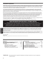
TABLE OF CONTENTS
Introduction . . . . . . . . . . . . . . . . . . . . . . . . . . . 2
Safety Instructions . . . . . . . . . . . . . . . . . . . . . . 3
Design Features . . . . . . . . . . . . . . . . . . . . . . 4-5
Installation . . . . . . . . . . . . . . . . . . . . . . . . . . 5-9
Installation Considerations . . . . . . . . . . . . . . . . 5
Mounting Locations. . . . . . . . . . . . . . . . . . . . . . 6
Battery and Charging . . . . . . . . . . . . . . . . . . . . 6
Wiring the System . . . . . . . . . . . . . . . . . . . . . . . 7
Operation . . . . . . . . . . . . . . . . . . . . . . . . . 10-11
Set-up Features . . . . . . . . . . . . . . . . . . . . . . . . 10
Front End Defeat . . . . . . . . . . . . . . . . . . . . . . . 10
Crossover . . . . . . . . . . . . . . . . . . . . . . . . . . . . . 10
Gain . . . . . . . . . . . . . . . . . . . . . . . . . . . . . . . . . . 11
Troubleshooting . . . . . . . . . . . . . . . . . . . . 11-12
Specifications . . . . . . . . . . . . . . . . . . . . . . . . . 12
Limited Warranty Information . . . . . . . . . . . . 13
NOTE: Review each section for more detailed information.
2
GETTING STARTED
Welcome to MB Quart! This manual is designed to provide information for the owner, salesperson and
installer. For those of you who want quick information on how to install this product, please turn to the
Installation Section of this manual. Other information can be located by using the Table of Contents. We, at
MB Quart, have worked very hard to make sure all the information in this manual is current. But, as we are
constantly finding new ways to improve our product, this information is subject to change without notice.
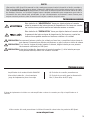
SAFETY INSTRUCTIONS
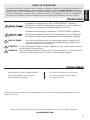
This symbol with “WARNING” is intended to alert the user to the
presence of important instructions. Failure to heed the instructions will
result in severe injury or death.
This symbol with “CAUTION” is intended to alert the user to the
presence of important instructions. Failure to heed the instructions can
result in injury or unit damage.
CAUTION:
To prevent injury and damage to the unit, please read and follow the instructions
in this manual. We want you to enjoy this system, not get a headache.
CAUTION
If you feel unsure about installing this system yourself, have it installed by an
authorized MB Quart dealer.
CAUTION
Before installation, disconnect the battery negative (-) terminal to prevent
damage to the unit, fire and/or possible injury.
CONTENTS OF CARTON
Model RAA4200 4-Channel Amplifier
(4) Speaker Plug Connectors
Installation & Operation Manual
(1) Power Plug Connector
Mounting Hardware Kit
(1) 8/32" Allen Wrench
The hardware kit included with each amplifier contains the mounting hardware necessary to secure the
amplifier to the vehicle.
Visit our web site for the latest information on all MB Quart products.
www.mbquart.com
3
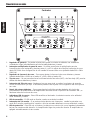
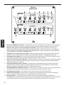
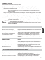
DESIGN FEATURES
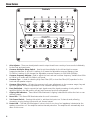
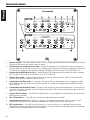
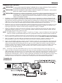
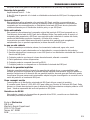
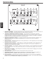
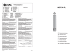
Controls
1.
Gain Adjuster – These can be adjusted to match output levels from a variety of source units individually
for the front and rear inputs.
2.
Crossover Multiplier Range Switch – Used to set the multiplier for the left and right crossover
frequencies between x1 and x10. A setting of x1 leaves the adjustable crossover frequency from
50-500Hz. A setting of x10 changes the adjustable crossover frequency to 500-5KHz (5000Hz)
3.
Crossover Frequency Adjuster– Used to adjust the front and rear crossover frequency. Variable from 50Hz
to 500Hz in x1 mode, and 500-5KHz in x10 mode.
4.
Crossover Type – Is used for selecting High-Pass Filter (HPF) or Low-Pass Filter (LPF) operation for the
front and rear speaker outputs.
5.
Crossover Filter Switch – Off sets the crossover to all-pass, adjustments to the crossover range, freq, and
type are bypassed. On allows adjustments to the crossover settings to be used.
6.
Front End Defeat – Used to reroute the input signal around the signal processing circuitry within the
amplifier. While in the ON position, all gain and crossover functions are bypassed.
7.
Clipping LED Indicators – These Yellow LEDs illuminate if clipping is detected for either the front or rear
channel outputs.
8.
Power LED – This Green LED illuminates when the unit is turned on.
9.
2/4 Channel Switch – Pressing this switch in, switches the inputs to a 2-channel mode, allowing
connection to only the front inputs with a 4-channel output.
10. Protect LED – This Red LED illuminates if a short circuit or too low of an impedance is detected at the
speaker connections or if the amplifier reaches thermal protection. The amplifier will automatically shut
down if this occurs.
4
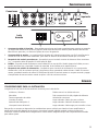
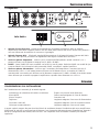
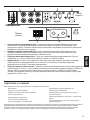
DESIGN FEATURES
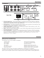
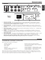
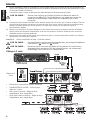
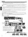
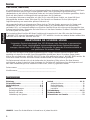
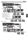
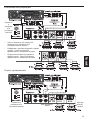
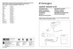
Connections
Left Side
Right Side
1.
RCA Line Output Jacks – These outputs provide a convenient source for daisy-chaining an additional
amplifier without running an extra set of RCA cables from the front of the vehicle. These are pass-thru
only and are not effected by crossover or gain adjustments.
2.
RCA Input Jacks – The industry standard RCA jacks provide an easy connection for line level input. They
are plated to resist the signal degradation caused by corrosion.
3.
Speaker Plug Receptacle – Receptacle for the speaker plug connector. These connectors (+ and –) will
accept wire sizes from 12 AWG to 18 AWG.
4.
Fuses – These ATC fuses are easily accessible in case of failure. Always replace fuses with same type and
rating. See Specifications for fuse ratings.
5.
Power Plug Receptacle – Receptacle for the power plug connector. The power (+12V DC) and ground
wire connectors will accommodate up to a 2 AWG wire. The Remote wire connector will accommodate
sizes from 12 AWG to 18 AWG. The Remote terminal is used to remotely turn-on and turn-off the
amplifier when +12V DC is applied.
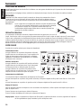
INSTALLATION
INSTALLATION CONSIDERATIONS
The following is a list of tools needed for installation:
Volt/Ohm Meter
Wire strippers
Wire crimpers
Wire cutters
#2 Phillips screwdriver
Battery post wrench
Hand held drill w/assorted bits
1/8" diameter heatshrink tubing
Assorted connectors
Adequate Length—Red Power Wire
Adequate Length—Remote Turn-on Wire
Adequate Length—Black Grounding Wire
This section focuses on some of the vehicle considerations for installing your new amplifier.
Pre-planning your system layout and best wiring routes will save installation time. When deciding on the
layout of your new system, be sure that each component will be easily accessible for making adjustments.
5
INSTALLATION
CAUTION:
If you feel unsure about installing this system yourself, have it installed by a
authorized MB Quart Dealer.
CAUTION:
Before installation, disconnect the battery negative (-) terminal to prevent
damage to the unit, fire and/or possible injury.
Before beginning any installation, follow these simple rules:
1.
Be sure to carefully read and understand the instructions before attempting to install the unit.
2.
For safety, disconnect the negative lead from the battery prior to beginning the installation.
3.
For easier assembly, we suggest you run all wires prior to mounting your unit in place.
4.
Route all of the RCA cables close together and away from any high current wires.
5.
Use high quality connectors for a reliable installation and to minimize signal or power loss.
6.
Think before you drill! Be careful not to cut or drill into gas tanks, fuel lines, brake or hydraulic lines,
vacuum lines or electrical wiring when working on any vehicle.
7.
Never run wires underneath the vehicle. Running the wires inside the vehicle provides the best protection.
8.
Avoid running wires over or through sharp edges. Use rubber or plastic grommets to protect any wires
routed through metal, especially the firewall.
9.
ALWAYS protect the battery and electrical system from damage with proper fusing. Install the appropriate
fuse holder and fuse on the +12V power wire within 18” (45.7 cm) of the battery terminal.
10. When grounding to the chassis of the vehicle, scrape all paint from the metal to ensure a good, clean
ground connection. Grounding connections should be as short as possible and always be connected to
metal that is welded to the main body, or chassis, of the vehicle.
MOUNTING LOCATIONS
Engine Compartment
Never mount this unit in the engine compartment. Mounting the unit in the engine compartment will void
your warranty.
Trunk Mounting
Mounting the amplifier vertically will provide adequate cooling of the amplifier.
Mounting the amplifier on the floor of the trunk will provide the best cooling of the amplifier.
Mounting the amplifier upside down to the rear deck of the trunk will not provide proper cooling and will
severely affect the performance of the amplifier and is strongly not recommended.
Passenger Compartment Mounting
Mounting the amplifier in the passenger compartment will work as long as you provide a sufficient amount of
air for the amplifier to cool itself. If you are going to mount the amplifier under the seat of the vehicle, you
must have at least 1" (2.54cm) of air gap around the amplifier's fan intake and top exhaust vents.
Mounting the amplifier with less than 1" (2.54cm) of air gap around the amplifier in the passenger
compartment will not provide proper cooling and will severely affect the performance of the amplifier and is
strongly not recommended.
BATTERY AND CHARGING
Amplifiers will put an increased load on the vehicle's battery and charging system. We recommend checking
your alternator and battery condition to ensure that the electrical system has enough capacity to handle the
increased load of your stereo system. Stock electrical systems which are in good condition should be able to
handle the extra load of any MB Quart amplifier without problems, although battery and alternator life can
be reduced slightly. To maximize the performance of your amplifier, we suggest the use of a heavy duty
battery and an energy storage capacitor.
6
INSTALLATION
WIRING THE SYSTEM
CAUTION:
If you do not feel comfortable with wiring your new unit, please see your local
authorized MB Quart Dealer for installation.
CAUTION:
Before installation, disconnect the battery negative (-) terminal to prevent
damage to the unit, fire and/or possible injury.
CAUTION:
Avoid running power wires near the low level input cables, antenna, power
leads, sensitive equipment or harnesses. The power wires carry substantial
current and could induce noise into the audio system.
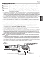
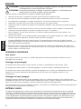
1.
Plan the wire routing. Keep RCA cables close together but isolated from the amplifier's power cables and
any high power auto accessories, especially electric motors. This is done to prevent coupling the noise
from radiated electrical fields into the audio signal. When feeding the wires through the firewall or any
metal barrier, protect them with plastic or rubber grommets to prevent short circuits. Leave the wires
long at this point to adjust for a precise fit at a later time.
2.
Remove the four (4) 8/32 allen head screws holding the connection end cover in place (this is the end
without the vents for the fans). Keep the cover and screws in a safe place for reinstallation when
mounting and wiring is complete.
3.
Prepare the RED wire (power cable) by stripping 1/2" of insulation from the end of the wire. Insert the
bared wire into the “+” terminal on the plug connector. Tighten the set screw with a 3/32" allen wrench
to secure the cable in place.
NOTE: The "+" (positive) cable MUST be fused 18" or less from the vehicle's battery. Install the fuseholder
under the hood and ensure connections are water tight.
4.
Trim the RED wire (power cable) within 18" of the battery and splice in a inline fuse holder. See
Specifications for the rating of the fuse to be used. DO NOT install the fuse at this time.
5.
Strip 1/2" from the battery end of the power cable and crimp a large ring terminal to the cable. Use the
ring terminal to connect to the battery positive terminal.
6.
Prepare the BLACK wire (Ground cable) by stripping 1/2" of insulation from the end of the wire. Insert the
bared wire into the “-” terminal on the plug connector. Tighten the set screw with a 3/32" allen wrench
to secure the cable in place. Prepare the vehicle chassis ground by scraping any paint from the metal
surface and thoroughly clean the area of all dirt and grease. Strip the other end of the wire and attach a
ring connector. Fasten the cable to the chassis using a non-anodized screw and a star washer.
NOTE:
7.
Keep the length of the BLACK wire (Ground) as short as possible. Always less than 30"(76.2cm).
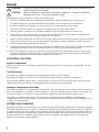
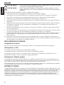
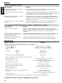
Prepare the Remote turn-on wire by stripping 1/2" of insulation from the end of the wire. Insert the
bared wire into the “R” terminal on the plug connector. Tighten the set screw with a 3/16" allen wrench
to secure the cable in place. Connect the other end of the Remote wire to a switched 12 volt positive
source. The switched voltage is usually taken from the source unit's accessory lead. If the source unit
does not have this output available, the recommended solution is to wire a mechanical switch in line
with a 12 volt source to activate the amplifier manually.
Power Connection
7
INSTALLATION
8.
Securely mount the amplifier to the vehicle or amp rack. Be careful not to mount the amplifier on
cardboard or plastic panels. Doing so may enable the screws to pull out from the panel due to road
vibration or sudden vehicle stops.
9.
Connect source signal by plugging the RCA cables into the input jacks at the amplifier.
CAUTION:
Always ensure power is off or disconnected at the amplifier before connecting
RCA cables. Failure to do so may cause injury, damage to the amplifier and/or
connected components.
10. Connect the speakers. Strip the speaker wires 1/2" and insert into the speaker plug connector and tighten
the set screw to secure into place. Be sure to maintain proper speaker polarity. DO NOT chassis ground
any of the speaker leads as unstable operation may result.
11. Perform a final check of the completed system wiring to ensure that all connections are accurate. Check
all power and ground connections for frayed wires and loose connections which could cause problems.
12. Ensure the amplifier is mounted securely and reinstall the end cover. Install an inline fuse near the
battery connection.
NOTE:
Follow the diagrams for proper signal polarity.
CAUTION:
These amplifiers are not recommended for impedance loads below 2
and 4 bridged.
CAUTION:
Do not attempt to connect the source units speaker leads directly to the RCA
connections of this amplifier, as damage to the source unit and/or the
amplifier may result.
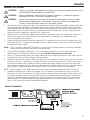
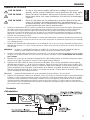
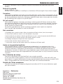
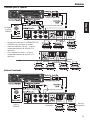
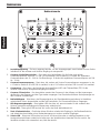
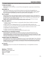
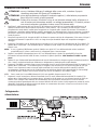
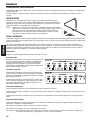
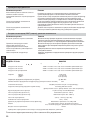
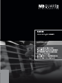
2-Channel Wiring
•
RCA Inputs connect to FRONT inputs only.
•
2/4 CH SWITCH push in to set to 2CH.
•
Gain (Front & Rear) - is set independently to
suit application.
•
Crossover (Front & Rear) - is set independently
to suit application.
8
stereo
INSTALLATION
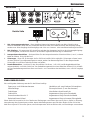
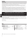
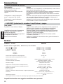
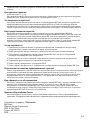
4-Channel Wiring
•
2/4 CH SWITCH push in to set to 4CH.
•
Gain (Front & Rear) - is set independently
to suit application.
•
Crossover (Front & Rear) - is set
independently to suit application.
Stereo Bridged
9
OPERATION
SET-UP FEATURES
The MB Quart R Series amplifier offers a wide range of selections for the user to create a listening
environment that meets your personal preference.
Before making final adjustments, read through the descriptions for each feature to get the best results.
ADJUSTMENTS
Loosen the allen screw holding the small cover in place over the controls. Tilt
the cover up and away from the amplifier. After making adjustments, always
ensure the cover is in place to prevent accidental changes to the settings.
NOTE: Failure to follow these instructions may result in a loss of sonic
quality. This is caused by premature activation of the protection
circuitry to maintain the integrity of the amplifiers sensitive
components. The performance specifications listed in this manual
cannot be guaranteed under such conditions.
FRONT END DEFEAT
The front-end defeat switch is responsible for rerouting the signal around the
signal processing circuitry within the amplifier. This feature was designed for use with external processors to
provide the purest possible signal path through the amplifier.
With this configuration, the MB Quart R Series amplifiers are able to provide lower distortion and better
signal reproduction due to the reduction in the number of components in the signal path. Bypassing the
crossover will also eliminate the typical phase shift associated with the analog filter transform function. While
the Front End Bypass is turned on, all adjustments made to the gain or crossover will be bypassed.
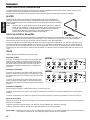
CROSSOVER
Do the following individually for each channel.
Filter Switch
Placing the switch in the ON position (In Position)
sets the amplifier to the All Pass mode, preventing
any crossover adjustment, allowing all frequencies
to pass. Adjustments made to the Multiplier switch
or Frequency Adjuster are bypassed.
Frequency Switch
Placing the switch in the HPF position (In Position)
sets the amplifier to the High Pass mode, enabling
frequencies above the cut-off point to pass.
Placing the switch in the LPF position (Out Position)
sets the amplifier to the Low Pass mode, enabling
frequencies below the cut-off point to pass.
Multiplier Switch
This switch sets the multiplier for the crossover frequencies.
Placing the switch in the x10 position (In Position) sets the adjustable crossover frequency to 500-5KHz
(5000Hz).
Placing the switch in the x1 position (Out Position) sets the adjustable crossover frequency to 50-500Hz.
Frequency Adjustment
After setting the Frequency Switch and Multiplier Switch, use the Frequency Adjuster to set the desired cutoff point.
Turning the adjuster counter-clockwise decreases the set frequency.
Turning the adjuster clockwise increases the set frequency.
Quick Setting: Decrease the crossover frequency all the way down. With the system playing, increase the crossover
frequency up slowly until the desired crossover point is achieved.
10
OPERATION
GAIN
Do the following individually for each channel.
Turning the adjuster clockwise decreases the set gain.
Turning the adjuster counter-clockwise increases the set gain.
1. To adjust the gain setting, turn the amplifier gains all the way down (clockwise).
2. Turn the source unit volume up until distortion is audible and then turn it down a bit until the distortion
is inaudible. This will be about all the way up on most source units.
3. Increase the amplifier gain setting until adequate volume is achieved or clipping is noted by the LED
indicators. Turn the gain down slightly if clipping is indicated.
Most quality source units do not distort, so the volume can be used at maximum setting.
NOTE: Best signal to noise and dynamic range are realized with the gain at minimum. Most users find
adequate gain and volume is achieved at about halfway in the adjustment range.
CAUTION:
Avoid setting the amplifier gain very high as noise and distortion will increase
significantly.
NOTE: For a more in depth setting procedure, contact MB Quart Technical Support.
TROUBLESHOOTING
Amplifier Does Not Turn On
Possible Cause
Solution
The in-line fuse on battery positive
cable is blown.
Check in-line fuse on battery positive cable. Replace if necessary.
Poor ground connection
Verify that Ground connection is connected to clean metal on the
vehicle’s chassis. Repair/replace if necessary.
Poor power connection or power
outside acceptable range.
Verify there is 10.5 - 15.5 Volts present at the positive battery and
remote turn-on cable. Verify quality connections for both cables at
amplifier, stereo, and battery/fuseholder. Repair/replace if necessary.
No Sound Coming From Amplifier
Possible Cause
Solution
Poor RCA connections.
Verify good RCA input connections at source and amplifier. Check
entire length of cables for kinks, splices, etc. Test RCA inputs for
AC voltage with the source unit on. Repair/replace if necessary
Poor speaker connections
Use an ohm meter to check speaker wire integrity. Check entire
length of wires for kinks, splices, etc. Repair/replace if necessary.
Bad source unit
Connect RCA input from test source directly to amplifier input. If
this solves the problem, have the source unit repaired or replaced.
If not, have the amplifier checked by a qualified technician.
Speaker "Pop" When Amplifier Turns On
Possible Cause
Solution
Remote from source unit comes on too
quickly.
Disconnect input signal to amplifier and turn amplifier on and off.
If the noise is eliminated, connect the REM lead of amplifier to
source unit with a delay turn-on module
Poor remote power signal from source
Use a different 12 Volt source for REM lead of amplifier (i.e.
battery direct). If the noise is eliminated, use a relay to isolate the
amplifier from noisy turn-on output.
11
TROUBLESHOOTING
Excessive Engine Noise
Possible Cause
Solution
RCA cables too close to main power
cables.
Route all signal carrying wires (RCA, Speaker cables) away from
power and ground wires.
Bad component in the signal chain
Bypass any and all electrical components between the source and
the amplifier(s). Connect source directly to input of amplifier. If
noise goes away the unit being bypassed is the cause of the noise.
Poor ground connection at system
components
Remove existing ground wires for all electrical components.
Reground wires to different locations. Verify that grounding
location is clean, shiny metal free of paint, rust etc
Poor ground connection at battery
Add secondary ground cable from negative battery terminal to the
chassis metal or engine block of vehicle.
PROT (Protect) LED Comes On, Amplifier shuts down
Possible Cause
Solution
There is a short in the system
Turn the system off. Check connection to all components for possible
shorts. Check all wires and cables for kinks, splices, poor insulation,
etc. Repair/replace if necessary.
Amplifier has exceeded normal
operating temperature due to improper
ventilation.
Turn the system off and allow to cool. Verify adequate ventilation
around amplifier. Move the amplifier to a spot with better ventilation
if needed.
Speaker impedance too low
Check for proper speaker impedance, replace if needed.
Low battery voltage
Check that the vehicle charging system is maintaining proper voltage.
SPECIFICATIONS
MODEL- R Series
RAA4200
Continuous Power Rating (RMS) - Measured at 14.4 Battery Volts
100 Watts x 4Ch and ≤ 1% THD+N
200 Watts x 4Ch and ≤ 1% THD+N
400 Watts x 2Ch and ≤ 1% THD+N
2.375" (6cm)
11.5" (29.2cm)
16.75" (42.5cm)
4 Load Per Channel
2 Load Per Channel
4 Load Bridged
Dimensions:
Height
Width
Length
Amplifier Fuse Rating (Amp/Type)
Battery Fuse Rating (Amp) External (Not Supplied)
Signal-to-Noise Ratio
Crossover (Front and Rear)
Crossover Slope
(3) 30A / ATC
90A
>80dB A-weighted (reference: 0dB = 2Vrms)
Selectable HPF/LPF or Off (High Pass / Low Pass or All Pass)
12dB/octave Butterworth
Crossover Frequency (Multiplier X1)
variable from 50Hz to 500Hz
Crossover Frequency (Multiplier X10)
variable from 500Hz to 5KHz
Frequency Response
0.25Hz to 100kHz (-3dB, 1watt)
Rated Bandwidth
Signal Voltage Adjustment Range (RCA Input)
Protection
Input Impedance
20Hz to 20kHz
Variable from 0.15V to 8V
Shorted output, DC offset,
thermal, power supply over-current
20k ohms
These specifications are Amplifier Power Standard CEA-2006 Compliant
Specifications subject to change without notice
12
LIMITED WARRANTY INFORMATION
MB Quart Corporation offers a limited warranty on MB Quart products on the following terms:
Length of Warranty
R Series Amplifiers – 1 Year
Or, two (2) years warranty if installed by a Authorized MB Quart Dealer. Requires proof of purchase.
What is Covered
This warranty applies only to MB Quart products sold to consumers by Authorized MB Quart Dealers
in the United States of America or its possessions. Product purchased by consumers from an
Authorized MB Quart Dealer in another country are covered only by that country’s Distributor and
not by MB Quart.
Who is Covered
This warranty covers only the original purchaser of MB Quart product purchased from an Authorized
MB Quart Dealer in the United States. In order to receive service, the purchaser must provide MB
Quart with a copy of the receipt stating the customer name, dealer name, product purchased and
date of purchase.
Products found to be defective during the warranty period will be repaired or replaced
(with a product deemed to be equivalent) at MB Quart's discretion.
What is Not Covered
1. Damage caused by accident, abuse, improper operations, water, theft, shipping
2. Any cost or expense related to the removal or reinstallation of product
3. Service performed by anyone other than MB Quart or an Authorized MB Quart Service Center
4. Any product which has had the serial number defaced, altered, or removed
5. Subsequent damage to other components
6. Any product purchased outside the U.S.
7. Any product not purchased from an Authorized MB Quart Dealer
Limit on Implied Warranties
Any implied warranties including warranties of fitness for use and merchantability are
limited in duration to the period of the express warranty set forth above. Some states do not allow
limitations on the length of an implied warranty, so this limitation may not apply. No person is
authorized to assume for MB Quart any other liability in connection with the sale of the product.
How to Obtain Service
Contact the Authorized MB Quart Dealer you purchased this product from.
If you need further assistance, call 1-800-962-4412 for MB Quart Customer Service. You must
obtain an RA# (Return Authorization number) to return any product to MB Quart. You are
responsible for shipment of product to MB Quart.
EU Warranty
This product meets the current EU warranty requirements, see your Authorized dealer for details.
Ship to: Electronics
MB Quart
Warranty Repair Department
2055 E. 5th Street
Tempe, AZ 85281
RA#: _________________________
13
INTRODUCTION
Français
Cher client,
Toutes nos félicitations pour avoir acheté un produit de la meilleure marque d'équipements audio pour automobile.
Chez MB Quart, nous sommes heureux que vous ayez choisi notre produit. Des années d'expertise en ingénierie, de
savoir-faire et d'essais poussés nous ont permis de créer une vaste gamme de produits capables de reproduire toute
la clarté et la richesse musicales que vous méritez.
Pour obtenir les meilleurs résultats, nous vous recommandons de faire installer votre nouvel appareil par un
distributeur MB Quart agréé. Prenez soin de lire la garantie et conservez votre reçu ainsi que l'emballage d'origine
pour usage ultérieur.
Pour monter un excellent système, il ne suffit pas de posséder un super produit et d'assurer une installation qualifiée
compétente. Vous devez veiller à ce que votre installateur utilise des accessoires de qualité. Des câbles RCA et un
câble de haut-parleurs de mauvaise qualité peuvent affecter la performance et la reproduction sonore de votre
système. Utilisez ce qu'il y a de mieux lorsque vous effectuez ou faites effectuer l'installation. Insistez pour les avoir!
Après tout, votre nouveau système ne mérite rien de moins.
Pour obtenir une brochure gratuite sur les produits et accessoires MB Quart,
appelez aux États-Unis le 1-800-962-7757 ou faxez au 1-800-327-3777.
Pour tous les autres pays, appelez le +49 6261 638-0 ou faxez au +49 6261 638-129.
PRATIQUEZ UNE ÉCOUTE SANS RISQUESM
Une exposition continue à des niveaux de pression acoustique supérieurs à 100 dB peut
causer une perte d'acuité auditive permanente. Les systèmes audio de forte puissance pour
auto peuvent produire des niveaux de pression acoustique bien supérieurs à 130 dB. Faites
preuve de bon sens et pratiquez une écoute sans risques.
Si vous avez encore des questions à propos de ce produit, même après avoir lu ce manuel, contactez votre
distributeur agréé MB Quart. Si vous avez besoin d'aide, appelez-nous au 1-800-962-4412 (+49 6261 638 125 pour
l'Europe). Veuillez avoir les numéros de modèle et de série, ainsi que la date d'achat de l'appareil à portée de main
lorsque vous appelez.
Le numéro de série est indiqué sur l'extérieur de l'emballage. Cela permettra de vérifier votre garantie et de retrouver
votre amplificateur en cas de vol.
Numéro de série : ____________________________________________
Numéro de modèle : __________________________________________
TABLE DES MATIÈRES
Introduction . . . . . . . . . . . . . . . . . . . . . . . . . . . 2
Consignes de sécurité . . . . . . . . . . . . . . . . . . . . 3
Particularités techniques . . . . . . . . . . . . . . . . 4-5
Installation . . . . . . . . . . . . . . . . . . . . . . . . . . 5-9
Considérations concernant l'installation . . . . . 5
Emplacements de montage. . . . . . . . . . . . . . . . 6
Batterie et charge . . . . . . . . . . . . . . . . . . . . . . . 6
Câblage du système. . . . . . . . . . . . . . . . . . . . . . 7
Fonctionnement . . . . . . . . . . . . . . . . . . . . 10-11
Fonctions de réglage . . . . . . . . . . . . . . . . . . . . 10
Dérivation frontale. . . . . . . . . . . . . . . . . . . . . . 10
Filtre passif (X.Over). . . . . . . . . . . . . . . . . . . . . 10
Gain . . . . . . . . . . . . . . . . . . . . . . . . . . . . . . . . . . 11
Dépannage . . . . . . . . . . . . . . . . . . . . . . . . 11-12
Spécifications . . . . . . . . . . . . . . . . . . . . . . . . . 12
Informations sur la garantie limitée . . . . . . . . 13
REMARQUE : Consultez chaque section pour de plus amples informations.
2
AVANT DE COMMENCER
CONSIGNES DE SÉCURITÉ
Le symbole accompagnant le mot « AVERTISSEMENT » signale à
l'utilisateur la présence d'instructions importantes. Le non-respect de
ces instructions causera des blessures graves ou la mort.
Le symbole accompagnant l'expression « MISE EN GARDE » signale à
l'utilisateur la présence d'instructions importantes. Le non-respect de
ces instructions peut causer des blessures ou endommager l'appareil.
MISE EN GARDE :
Pour éviter des blessures et ne pas endommager l'appareil, veuillez lire et
suivre les instructions de ce manuel. Nous espérons que ce système vous
procurera du plaisir et non des tracas.
ATTENTION
Si vous vous sentez incapable d'installer l'appareil par vous-même, confiez la tâche à
un distributeur MB Quart agréé.
ATTENTION
Avant d'entamer l'installation, déconnectez la broche négative (-) de la batterie pour
éviter tout risque de blessures, d'incendie ou de dommages à l'appareil.
CONTENU DE L'EMBALLAGE
Amplificateur à 4 voies, modèle RAA4200
(4) Fiches de connexion de haut-parleur
Manuel d'installation et d'utilisation
(1) Fiche de connexion d'alimentation
Kit de matériel de montage
(1) Clé Allen 8/32 po
Le kit de matériel inclus avec chaque amplificateur contient le matériel de montage nécessaire pour fixer
l'ampli au véhicule.
Visitez notre site Web pour obtenir les dernières informations sur tous les produits MB Quart.
www.mbquart.com
3
Français
Bienvenue à MB Quart! Ce manuel vise à informer le propriétaire, le vendeur et l'installateur de l'appareil. Si
vous désirez apprendre rapidement comment installer ce produit, consultez la section Installation du manuel.
Reportez-vous à la Table des matières pour d'autres informations. Nous nous efforçons de faire en sorte que
toutes les informations contenues dans ce manuel soient à jour. Cependant, du fait de l'amélioration
constante de nos produits, nous nous réservons le droit de modifier ces informations sans aucun préavis.
Français
PARTICULARITÉS TECHNIQUES
Commandes
1.
Ajusteur de gain - Peut être réglé de façon à faire correspondre individuellement les niveaux de sortie de
diverses unités source aux entrées avant et arrière.
2.
Commutateur de multiplication de filtre – Permet de paramétrer le multiplicateur pour les fréquences
de filtre gauche et droite entre x1 et x10. Un réglage de x1 maintient la fréquence réglable du filtre entre
50-500 Hz. Un réglage de x10 modifie la fréquence réglable du filtre de 500 Hz à 5 kHz (5000 Hz).
3.
Ajusteur de multiplication de filtre – Permet d'ajuster les fréquences de filtre avant et arrière. Variable
de 50 à 500 Hz en mode x1, et de 500 Hz à 5 kHz en mode x10.
4.
Type de filtre passif – Permet de sélectionner les modes de filtre passe-haut (HPF) ou passe-bas (LPF)
pour les sorties de haut-parleur avant et arrière.
5.
Commutateur de filtre passif – En position Off, met le filtre en mode passe-tout; les réglages de filtre,
de fréquence et de type sont contournés. En position On, permet aux réglages des paramètres de filtre
d'être utilisés.
6.
Commutateur de dérivation frontal - Permet de réacheminer le signal d'entrée de façon à contourner le
circuit de traitement de signal au sein de l'ampli. En position ON, toutes les fonctions de gain et de filtre
passif sont contournées.
7.
Voyants DEL d'écrêtage – Ces DEL jaunes s'illuminent en cas de détection d'écrêtage aux sorties de hautparleur avant ou arrière.
8.
DEL d'alimentation – Cette DEL verte s'illumine lorsque l'appareil est allumé.
9.
Commutateur de canal 2/4 – Quand on l'enfonce, ce commutateur passe en mode 2 canaux, ce qui
permet une connexion aux entrées avant seulement en présence d'une sortie à 4 canaux.
10. DEL de protection – Cette DEL rouge s'illumine si un court-circuit ou une impédance trop basse est
détecté au niveau des connexions de haut-parleur ou si l'ampli atteint le niveau de protection thermique.
L'ampli s'éteint automatiquement si cela se produit.
4
PARTICULARITÉS TECHNIQUES
Connexions
Français
Ponté à
gauche
Ponté à
droite
1.
Prises de sortie RCA –Ces sorties permettent de connecter en guirlande un second ampli en évitant
d'acheminer des câbles RCA supplémentaires de l'avant du véhicule. Il s'agit d'extensions ampli qui ne
sont pas affectées par les réglages de filtre ou de gain.
2.
Prises d'entrée RCA – Les prises RCA de norme industrielle permettent une connexion facile pour les
entrées de niveau de ligne. Elles sont plaquées pour résister à la détérioration de signal due à l'effet de la
corrosion.
3.
Prise de haut-parleur – Prise de la fiche de connexion de haut-parleur. Ces fiches (+ et –) acceptent des
câbles de calibre 12 AWG à 18 AWG.
4.
Fusibles - Ces fusibles ATC sont facilement accessibles en cas de défaillance. Remplacez toujours les
fusibles par des fusibles de type et de capacité identiques. Voir les Spécifications en ce qui concerne la
capacité des fusibles.
5.
Prise d'alimentation – Prise pour la fiche d'alimentation. Les connecteurs d'alimentation (+12V c.c.) et de
masse sont prévus pour des câbles de calibre inférieur ou égal à 2 AWG. Le connecteur de fil de
télécommande accepte des câbles de calibre 12 AWG à 18 AWG. La borne de télécommande permet
d'allumer et d'éteindre l'ampli à distance lorsque le courant (+12 V c.c.) est mis.
INSTALLATION
CONSIDÉRATIONS CONCERNANT L'INSTALLATION
Voici la liste d'outils requis pour l'installation :
Voltmètre-ohmmètre
Pince à dénuder
Pince à sertir
Coupe-fils
Tournevis à embout cruciforme no. 2
Clé de borne de batterie
Perceuse à main avec mèches assorties
Tube thermorétrécissable de 1/8 po de diamètre
Connecteurs assortis
Longueur adéquate — Fil d'alimentation rouge
Longueur adéquate — Fil d'allumage à distance
Longueur adéquate — Fil de masse noir
Cette section traite de points concernant le véhicule dont il faut tenir compte pour l'installation de votre nouvel
ampli. Vous sauverez du temps en planifiant à l'avance la disposition du système et du câblage. Assurez-vous, entre
autres, que chaque composant du système est facilement accessible pour les réglages.
5
Français
INSTALLATION
MISE EN GARDE :
Si vous vous sentez incapable d'installer l'appareil par vous-même, confiez
la tâche à un distributeur MB Quart agréé.
MISE EN GARDE :
Avant d'entamer l'installation, déconnectez la broche négative (-) de la
batterie pour éviter tout risque de blessures, d'incendie ou de dommages à
l'appareil.
Avant de commencer l'installation, suivez ces règles toutes simples :
1.
Prenez soin de bien lire et comprendre les instructions avant d'installer l'appareil.
2.
Par mesure de sécurité, veuillez débrancher le fil négatif de la batterie avant de commencer l'installation.
3.
Pour faciliter le montage, nous vous suggérons de dérouler tous les câbles avant d'installer l'appareil.
4.
Acheminez tous les câbles RCA de façon groupée, à l'écart des fils à courant élevé.
5.
Utilisez des connecteurs de haute qualité pour assurer une installation fiable et minimiser la perte de signal ou
de puissance.
6.
Réfléchissez avant de percer quoique ce soit! Faites attention de ne pas couper ou percer le réservoir d'essence,
les conduites de carburant, de frein, hydrauliques ou de dépression, ou le câblage électrique lorsque vous
travaillez sur un véhicule.
7.
Ne faites jamais passer les fils sous le véhicule. Il vaut mieux les installer à l'intérieur du véhicule pour assurer
une meilleure protection.
8.
Évitez de faire passer les fils par dessus ou à travers des bords tranchants. Tout fil acheminé à travers du métal,
un pare-feu en particulier, doit être protégé avec des bagues en caoutchouc ou en plastique.
9.
Protégez TOUJOURS la batterie et le circuit électrique des dommages potentiels à l'aide de fusibles. Installez un
porte-fusible et un fusible appropriés sur le câble d'alimentation de +12 V à moins de 45,7 cm (18 po) de la
borne de batterie.
10. Préparez la masse du châssis en grattant toute trace de peinture de la surface métallique afin d'assurer une
bonne mise à la masse. Les connexions de masse doivent être aussi courtes que possible et toujours connectées à
du métal soudé à la carrosserie ou au châssis du véhicule.
EMPLACEMENTS DE MONTAGE
Compartiment du moteur
Ne montez jamais l'appareil dans le compartiment moteur car cela entraînera l'annulation de la garantie.
Montage dans le coffre
Un montage vertical de l'ampli assure un refroidissement adéquat.
Le montage de l'ampli sur le plancher du coffre assure un refroidissement optimal.
Le montage de l'ampli à l'envers, sur la tablette arrière, n'assure pas un refroidissement satisfaisant, nuit à la
performance de l'ampli et est, pas conséquent, fortement déconseillé.
Montage dans l'habitacle passager
Le montage de l'ampli dans l'habitacle passager est acceptable à condition que l'ampli reçoive suffisamment d'air
pour refroidir. Si vous comptez installer l'ampli sous le siège du véhicule, prévoyez un intervalle d'au moins 2,54 cm
(1 po) autour de la prise d'air du ventilateur et des évents de sortie du haut de l'ampli.
Un intervalle inférieur à cela autour de l'ampli dans l'habitacle passager n'assure pas un refroidissement satisfaisant,
nuit à la performance de l'ampli et est, pas conséquent, fortement déconseillé.
BATTERIE ET CHARGE
Les amplificateurs exercent une charge accrue sur la batterie et le système de charge du véhicule. Nous vous
conseillons de vérifier l'état de l'alternateur et de la batterie pour vous assurer que le système électrique peut
supporter la charge accrue de votre système stéréo. Les systèmes électriques ordinaires en bon état sont
normalement capables de fournir sans problème la charge supplémentaire requise par les amplis MB Quart.
Toutefois, la durée de vie de la batterie et de l'alternateur peut s'en trouver affectée légèrement. Pour
maximiser la performance de votre ampli, nous vous suggérons d'utiliser une batterie à usage intensif et un
condensateur de stockage d'énergie.
6
INSTALLATION
CÂBLAGE DU SYSTÈME
Si vous ne vous sentez capable d'effectuer le câblage de votre nouvel
appareil, veuillez confier l'installation à votre distributeur MB Quart agréé.
MISE EN GARDE :
Avant d'entamer l'installation, déconnectez la broche négative (-) de la
batterie pour éviter tout risque de blessures, d'incendie ou de dommages à
l'appareil.
MISE EN GARDE :
Évitez de faire passer les fils d'alimentation près des câbles d'entrée bas
niveau, de l'antenne, des câbles d'alimentation, des équipements ou
faisceaux sensibles. Les fils d'alimentation transportent un courant élevé et
peuvent produire du bruit dans le système audio.
Français
MISE EN GARDE :
1.
Planifiez l'acheminement des fils. Gardez les câbles RCA ensemble mais en les isolant des câbles d'alimentation
de l'ampli et des autres accessoires automobiles de forte puissance, particulièrement les moteurs électriques,
pour éviter que le signal audio ne subisse d'interférence de bruit provenant de champs de rayonnement
électriques. Si vous faites passer les fils par un pare-feu ou autre barrière métallique, protégez-les à l'aide de
bagues en caoutchouc ou en plastique pour éviter les courts-circuits. Conservez toute la longueur des fils pour
l'instant. Vous l'ajusterez plus tard.
2.
Retirez les quatre (4) vis Allen 8/32 retenant le couvercle d'extrémité des connexions (extrémité sans évents de
ventilateurs). Gardez le couvercle et les vis en lieu sûr afin de pouvoir les remettre en place une fois le montage
et le câblage terminés.
3.
Préparez le fil ROUGE (câble d'alimentation) qui en dénudant 1,6 cm (1/2 po) de son extrémité. Insérez la partie
dénudée dans la borne « + » de la fiche de connexion. Serrez la vis sans tête à l'aide d'une clé Allen 3/32 po pour
fixer le câble.
REMARQUE : Le câble « + » (positif) DOIT comporter un fusible à 45,7 cm (18 po) ou moins de la batterie du véhicule.
Installez le porte-fusible sous le capot et assurez-vous que les connexions sont étanches.
4.
Coupez le fil ROUGE (câble d'alimentation) à moins de 45,7 cm (18 po) de la batterie et épissez un porte-fusible
en ligne. Voir les Spécifications en ce qui concerne la capacité du fusible à utiliser. N'INSTALLEZ PAS le fusible
pour l'instant.
5.
Dénudez 1,6 cm (1/2 po) de l'extrémité de batterie du câble d'alimentation et sertissez une grosse cosse à
anneau sur le câble. Connectez la cosse à la borne positive de la batterie.
Préparez le fil NOIR (câble de mise à la masse) en dénudant 1/2 po de son extrémité. Insérez la partie
dénudée dans la borne « - » de la fiche de connexion. Serrez la vis sans tête à l'aide d'une clé Allen 3/32
po pour fixer le câble. Préparez la masse du châssis du véhicule en grattant toute trace de peinture de la
surface métallique et en nettoyant soigneusement pour éliminer tout dépôt de saleté et de graisse.
Dénudez l'autre extrémité du fil et fixez un connecteur en anneau. Fixez le câble au châssis à l'aide d'une
vis non anodisée et une rondelle en étoile.
6.
REMARQUE :
7.
Gardez le fil NOIR (masse) aussi court que possible. Toujours inférieur à 76,2 cm (30 po).
Préparez le fil d'allumage à distance en dénudant 1,6 cm (1/2 po) de son extrémité. Insérez la partie dénudée dans
la borne « R » de la fiche de connexion. Serrez la vis sans tête à l'aide d'une clé Allen 3/16 po pour fixer le câble.
Connectez l'autre extrémité du fil d'allumage à distance à une source positive commutée de 12 volts. La tension
commutée provient généralement du câble d'accessoire de la source audio. Si la source audio ne comporte pas
une telle sortie, nous recommandons de raccorder un interrupteur mécanique en ligne avec une source de 12 volts
pour activer l'ampli manuellement.
Connexion
d'alimentation
7
Français
INSTALLATION
8.
Montez solidement l'ampli sur le véhicule ou le rack d'ampli. Prenez soin de ne pas le fixer sur des panneaux en
carton ou en plastique. Les vis pourraient en effet se décoller des panneaux sous l'effet des vibrations de la route
ou des arrêts soudains du véhicule.
9.
Connectez le signal à l'ampli en branchant les câbles RCA dans les prises d'entrée de l'ampli.
MISE EN GARDE :
Assurez-vous toujours que l'ampli est éteint ou débranché avant de
connecter les câbles RCA. Toute négligence à cet égard peut causer des
blessures ou endommager l'ampli et/ou les composants qui lui sont
connectés.
10. Connectez les haut-parleurs. Dénudez les fils des haut-parleurs de 1,6 cm (1/2 po) et insérez-les dans la fiche de
connexion de haut-parleur, puis serrez la vis sans tête pour fixer le tout. Veillez à respecter la polarité des hautparleurs. NE mettez PAS les fils de haut-parleur à la masse sur le châssis, car cela pourrait causer un
fonctionnement instable.
11. Effectuez une vérification finale du câblage pour vous assurer que toutes les connexions sont bien effectuées.
Vérifiez toutes les connexions d'alimentation et de mise à la masse en vue de fils effilochés et de connexions
desserrées pouvant causer des problèmes.
12. Assurez-vous que l'ampli est bien monté, puis remettez en place le couvercle d'extrémité. Installez un fusible en
ligne près de la connexion de la batterie.
REMARQUE :
Vérifiez les polarités de signal à l'aide des schémas.
MISE EN GARDE :
Ces amplificateurs ne sont pas recommandés pour des charges d'impédance
inférieures à 2 stéréo et 4 pontées.
MISE EN GARDE :
Ne tentez pas de connecter les câbles de haut-parleur de l'unité source
directement aux connexions RCA de cet amplificateur, car cela pourrait
endommager l'unité source et/ou l'amplificateur.
Câblage à 2 voies
Régler sur 2
voies
•
Entrées RCA connectées à l'AVANT seulement.
•
COMMUTATEUR 2/4 VOIES - Enfoncer pour
régler sur 2 voies.
•
Gain (avant et arrière) - Réglé de façon
indépendante selon l'application.
•
Filtre passif (avant et arrière) - Réglé de façon
indépendante selon l'application.
8
INSTALLATION
Câblage à 4 canaux
Français
Régler sur
4 voies
•
COMMUTATEUR 2/4 VOIES - Enfoncer pour
régler sur 4 voies.
•
Gain (avant et arrière) - Réglé de façon
indépendante selon l'application.
•
Filtre passif (avant et arrière) - Réglé de
façon indépendante selon l'application.
Ponté stéréo
Régler sur 4
voies
Ponté à
gauche
Ponté à
droite
9
FONCTIONNEMENT
Français
FONCTIONS DE RÉGLAGE
L'amplificateur MB Quart de série R offre à l'utilisateur une vaste gamme de sélections qui lui permet de créer l'environnement
sonore qu'il préfère.
Avant d'effectuer les réglages ultimes, veuillez lire les descriptions de chaque fonction afin d'obtenir les meilleurs résultats.
RÉGLAGES
Desserrez la vis Allen retenant le petit couvercle au-dessus des commandes. Inclinez le
couvercle vers le haut en l'éloignant de l'ampli. Après avoir effectué les réglages, assurezvous toujours que le couvercle est remis en place pour éviter toute modification accidentelle
des paramètres.
REMARQUE :
Le non-respect de ces consignes peut entraîner une perte de qualité sonore.
Cela est dû à une activation prématurée du circuit de protection nécessaire
pour préserver l'intégrité des composants sensibles des amplis. Les
caractéristiques de performance listées dans ce manuel ne peuvent être
garanties sous de telles conditions.
DÉRIVATION FRONTALE
Le commutateur de dérivation frontale se charge de réacheminer le signal autour du circuit de traitement de signal au sein de
l'ampli. Cette fonction a été conçue pour des processeurs externes afin de fournir le trajet de signal le plus pur à travers l'ampli.
Grâce à cette configuration, les amplificateurs MB Quart de série R sont capables de fournir une distorsion inférieure et une
meilleure reproduction de signal à cause de la réduction du nombre de composants dans le trajet du signal. Contourner le filtre
permet également d'éliminer le déphasage typique associé à la fonction de transformation de filtre analogique. Lorsque la
dérivation frontale est activée, tous les réglages de gain ou du filtre passif sont contournés.
FILTRE PASSIF
Procédez de la manière suivante pour chaque voie séparément.
Commutateur de filtre
Lorsque le sélecteur est en position ON (position enfoncée),
l'amplificateur est en mode passe-tout, ce qui empêche tout
filtrage et laisse passer toutes les fréquences. Les réglages
appliqués au commutateur de multiplication ou à l'ajusteur
de fréquence sont contournés.
Sélecteur de fréquence
Lorsque le sélecteur est en position HPF (position enfoncée),
l'amplificateur est en mode passe-haut, ce qui laisse passer
les fréquences situées au-dessus du point de coupure.
Lorsque le sélecteur est en position LPF (position sortie),
l'amplificateur est en mode passe-bas, ce qui laisse passer les
fréquences situées au-dessous du point de coupure.
Commutateur de multiplication
Ce commutateur règle la multiplication des fréquences du filtre passif.
Lorsque l'interrupteur est en position x10 (position enfoncée), la fréquence réglable du filtre passif est de 500 Hz à 5 kHz (5000
Hz).
Lorsque l'interrupteur est en position x1 (position sortie), la fréquence réglable du filtre passif est de 50 à 500 Hz.
Réglage de fréquence
Après le réglage du sélecteur de fréquence et du commutateur de multiplication, utilisez l'ajusteur de fréquence pour régler le
point de coupure voulu.
Tournez l'ajusteur vers la gauche pour réduire la fréquence.
Tournez la molette de réglage vers la droite pour augmenter la fréquence.
Réglage rapide : Baissez complètement la fréquence du filtre passif. Le système audio étant en marche, augmentez la fréquence
du filtre graduellement jusqu'à atteindre le point de fréquence voulu.
10
FONCTIONNEMENT
GAIN
Tournez l'ajusteur vers la gauche pour réduire le gain.
Tournez l'ajusteur vers la droite pour augmenter le gain.
1. Pour régler le gain, tournez le bouton de gain de l'ampli vers son niveau le plus bas (sens contraire des aiguilles d'une
montre).
REMARQUE : Lorsque vous utilisez la télécommande de niveau et d'accentuation des fréquences avec cet appareil,
prenez soin de baisser au minimum la commande de niveau (bouton gauche) avant d'effectuer les
réglages.
2. Augmentez le volume de la source audio jusqu'à produire une distorsion audible, puis baissez-le jusqu'à ce que la
distorsion devienne inaudible. Cela correspondant généralement au maximum du volume sur la plupart des unités
source.
3. Augmentez le gain de l'ampli jusqu'à ce que le volume soit adéquat ou que les voyants DEL indiquent de l'écrêtage.
Diminuez le gain légèrement en cas d'écrêtage.
La plupart des sources audio ne produisent pas de distorsion, vous pouvez donc mettre le volume au maximum.
Mettez le gain au minimum pour assurer le meilleur rapport signal/bruit et la meilleure gamme
dynamique. Pour la plupart des utilisateurs, un réglage au milieu assure un niveau de gain et de volume
adéquat.
REMARQUE :
MISE EN GARDE :
REMARQUE :
Évitez de régler le gain de l'ampli trop haut car cela entraîne une augmentation
significative du bruit et des distorsions.
Pour une procédure de réglage plus approfondie, communiquez avec le support technique de MB Quart.
DÉPANNAGE
L'ampli ne s'allume pas.
Cause possible
Solution
Le fusible en ligne du câble positif de la
batterie est grillé
Vérifiez le fusible en ligne du câble positif de batterie. Effectuez un
remplacement au besoin.
Mauvaise connexion à la masse
Vérifiez que la connexion de mise à la masse est branchée à une surface
métallique propre du châssis du véhicule. Procédez à une réparation ou un
remplacement si nécessaire.
Mauvaise connexion d'alimentation ou
alimentation insuffisante.
Vérifiez la présence d'un courant de 10,5 à 15,5 volts au niveau de la borne
positive de la batterie et du câble d'allumage à distance. Vérifiez la qualité
des connexions des deux câbles au niveau de l'ampli, de la stéréo, de la
batterie et du porte-fusible. Procédez à une réparation ou un
remplacement si nécessaire.
Aucun son en provenance de l'ampli
Cause possible
Solution
Mauvaises connexions RCA.
Vérifiez que les connexions d'entrée RCA sont correctes au niveau de la
source audio et de l'ampli. Vérifiez s'il y a des problèmes de torsion ou
d'épissure tout le long des câbles, etc. Testez la présence de tension c.a. au
niveau des entrées RCA lorsque la source audio est allumée. Procédez à une
réparation ou un remplacement si nécessaire.
Mauvaises connexions de haut-parleur
Utilisez un ohmmètre pour contrôler l'intégrité du câble de haut-parleur.
Vérifiez s'il y a des problèmes de torsion ou d'épissure tout le long des
câbles, etc. Procédez à une réparation ou un remplacement si nécessaire.
Unité source défectueuse
Branchez directement l'entrée RCA de la source test à l'entrée de l'ampli. Si
cela résout le problème, faites réparer ou remplacer l'unité source. Sinon,
faites vérifier l'ampli par un technicien qualifié.
Le haut-parleur « claque » lorsque l'ampli est allumé
Cause possible
Solution
Le signal de télécommande de l'unité
source se produit trop rapidement.
Débranchez le signal d'entrée reçu par l'ampli, puis allumez et éteignez
l'ampli. Si le bruit disparaît, connectez le fil REM de l'ampli à la source
audio avec un module d'allumage temporisé.
Mauvais signal de télécommande en
provenance de la source
Utilisez une source de 12 Volts différente pour le fil REM de l'ampli (p. ex.,
directement de la batterie). Si le bruit disparaît, utilisez un relais pour isoler
l'ampli du signal bruyant au démarrage.
11
Français
Procédez de la manière suivante pour chaque voie séparément.
DÉPANNAGE
Français
Bruit de moteur excessif
Cause possible
Solution
Câbles RCA trop rapprochés des câbles
d'alimentation principaux.
Acheminez tous les fils de signal (RCA, câbles de haut-parleur) à
l'écart des fils d'alimentation ou de masse.
Composant défectueux dans la chaîne de
signal
Contournez tous les composants électriques situés entre la source et le
ou les amplis. Connectez la source directement à l'entrée de l'ampli. Si
le bruit disparaît, l'unité contournée est la cause du bruit.
Mauvaise connexion de mise à la masse
des composants du système
Retirez les fils de masse de tous les composants électriques. Branchez
de nouveau les fils à la masse, mais à des emplacements différents.
Vérifiez que ceux-ci sont propres, que le métal est brillant sans trace
de peinture, ni rouille, etc.
Mauvaise connexion de mise à la masse de
la batterie
Ajoutez un deuxième fil de masse allant de la borne négative de la
batterie au métal du châssis ou au bloc-moteur du véhicule.
Le voyant DEL PROT (Protection) s'allume, l'amplificateur s'éteint
Cause possible
Solution
Court-circuit dans le système
Éteignez le système. Vérifiez s'il y a des courts-circuits dans les composants.
Vérifiez s'il y a des problèmes de torsion, d'épissure, de mauvaise isolation le long
des fils et câbles, etc. Procédez à une réparation ou un remplacement si
nécessaire.
L'ampli a dépassé la température de
fonctionnement normale à cause
d'une mauvaise ventilation.
Éteignez le système et laissez-le refroidir. Vérifiez que la ventilation est adéquate
autour de l'ampli. Déplacez l'ampli vers un lieu mieux ventilé si nécessaire.
Impédance de haut-parleur trop basse
Vérifiez que l'impédance de haut-parleur est bonne. Remplacez au besoin.
Faible tension de batterie
Vérifiez que le système de charge du véhicule assure une tension adéquate.
CARACTÉRISTIQUES
MODÈLE - Série R
RAA4200
Puissance nominale en continu (RMS) - Mesurée à 14,4 V (batterie)
Charge de 4 par voie
Charge de 2 par voie
4
charge pontée
Dimensions :
100 watts x 4 voies et ≤ 1% THD+N
200 watts x 4 voies et ≤ 1% THD+N
400 watts x 2 voies et ≤ 1% THD+N
Hauteur
Largeur
Longueur
2,375 po (6 cm)
11,5 po (28,2 cm)
16,75 po (42,5 cm)
Capacité du fusible de l'ampli (ampères/type)
Capacité du fusible de la batterie (Ampères) externe (non fourni)
Rapport signal/bruit
Filtre passif (avant et arrière)
(3) 30A / ATC
90 A
>80 dB(A) (référence : 0 dB = 2 V RMS)
Sélectable HPF/LPF ou Off
(filtre passe-haut / passe-bas ou passe-tout)
Pente d'atténuation du filtre
12 dB/octave Butterworth
Fréquence du filtre (multiplicateur x1)
variable de 50 Hz à 500 Hz
Fréquence du filtre (multiplicateur x10)
Réponse en fréquence
variable de 500 Hz à 5000 Hz
de 0,25 Hz à 100 kHz (-3 dB, 1 watt)
Bande passante nominale
Plage de réglage de tension de signal (entrée RCA)
Protection
Impédance d'entrée
20 Hz à 20 kHz
Variable de 0.15 V à 8 V
Sortie court-circuitée, DC offset,
thermique, surintensité de courant d'alimentation
20 k-ohms
Ces spécifications sont conformes à la norme CEA-2006 portant sur la puissance des amplificateurs
Les spécifications sont sujettes à changements sans préavis
12
INFORMATIONS SUR LA GARANTIE LIMITÉE
MB Quart Corporation offre une garantie limitée sur les produits MB Quart selon les termes
suivants :
Français
Durée de la garantie
Amplis de série R – 1 an
Ou deux (2) ans de garantie si installé par un distributeur MB Quart agréé. Preuve d'achat exigée.
Couverture
Cette garantie s'applique uniquement aux produits MB Quart vendus à des consommateurs par des
distributeurs agréés MB Quart, aux États-Unis d'Amérique et leurs territoires. Les produits achetés
par des consommateurs auprès d'un distributeur agréé MB Quart dans un autre pays sont couverts
par le distributeur de ce pays et non par MB Quart.
Qui est couvert?
Cette garantie s'applique uniquement à l'acheteur initial du produit MB Quart acheté aux ÉtatsUnis auprès d'un distributeur agréé MB Quart. Afin de bénéficier du service de garantie, l'acheteur
doit fournir à MB Quart une copie du reçu indiquant le nom du client, le nom du distributeur, le
produit acheté et la date d'achat.
Les produits jugés défectueux durant la période de garantie seront réparés ou remplacés
(par un produit jugé équivalent) au choix de MB Quart.
Non-couverture
1. Dommages pour cause d'accident, d'abus, de mauvaise utilisation, d'eau, de vol, de transport.
2. Coûts et frais relatifs au retrait ou à la réinstallation du produit
3. Service effectué par quelqu'un d'autre que MB Quart ou qu'un centre de service autorisé MB Quart
4. Tout produit dont le numéro de série a été oblitéré, altéré ou enlevé
5. Dommages subséquents infligés à d'autres composants
6. Tout produit acheté en dehors des États-Unis
7. Tout produit n'ayant pas été acheté auprès d'un distributeur MB Quart agréé
Limite sur les garanties implicites
Toute garantie implicite, y compris toute garantie d'adéquation à un usage particulier et de
commercialité, est limitée dans le temps à la période de la garantie expresse énoncée ci-dessus.
Certaines juridictions ne permettent pas de limitation sur la durée des garanties implicites. En
conséquence, l'exclusion ci-dessus peut ne pas s'appliquer à vous. Aucune personne n'est autorisée
à assumer une quelconque autre responsabilité au nom de MB Quart en ce qui concerne la vente de
ce produit.
Pour l'obtention de service
Contactez le distributeur MB Quart agréé qui vous a vendu ce produit.
Si vous avez besoin d'aide, appelez le service à la clientèle MB Quart au 1-800-962-4412. Vous
devez obtenir un numéro d'autorisation de retour de marchandise avant de renvoyer le produit à MB
Quart. La responsabilité de l'envoi du produit à MB Quart vous incombe entièrement.
Garantie de l'Union européenne
Ce produit est conforme aux exigences de garantie actuelles de l'UE. Voir votre distributeur agréé
pour plus de détails.
Expédier à : Electronics
MB Quart
Warranty Repair Department
2055 E. 5th Street
Tempe, AZ 85281
Numéro d'autorisation de retour de
marchandise : __________________
13
INTRODUCCIÓN
Estimado cliente,
Español
Felicitaciones por su compra de la mejor marca del mundo de equipo de sonido para el automóvil. En MB
Quart estamos muy complacidos porque escogió nuestro producto. Con muchos años de experiencia en
ingeniería, conocimiento del oficio y procedimientos de prueba críticos, hemos creado una amplia gama de
productos para reproducción musical con toda la claridad y la riqueza que usted merece.
Para obtener el mejor rendimiento, le recomendamos que su nuevo producto MB Quart sea instalado por un
Distribuidor Autorizado de MB Quart. Por favor lea la garantía, conserve el recibo y la caja original para que los use
como posible referencia futura.
Cuando se trata de su sistema, la excelencia del producto y la instalación competente sólo representan una pieza del
rompecabezas. Asegúrese de que la persona que instale su sistema utilice accesorios de calidad al hacer la
instalación. Cables RCA y de altavoz de poca calidad pueden afectar el rendimiento y la calidad del sonido de su
sistema. Al instalar, o al hacer que se instale su sistema, use lo mejor. ¡Insista en ello! Después de todo, su nuevo
sistema sólo merece lo mejor.
Para obtener un folleto gratis de los productos y accesorios de MB Quart,
en los EE.UU. llame al 1-800-962-7757 o por FAX 1-800-327-3777.
Para todos los demás países, llame al +49 6261 638-0 o por FAX +49 6261 638-129.
PRACTIQUE EL SONIDO SEGURO
El contacto continuo con niveles de presión de sonido superiores a 100 dB puede causar la
pérdida permanente de la audición. Los sistemas de sonido de alta potencia para
automóviles pueden producir niveles de presión de sonido superiores a los 130 dB. Aplique
el sentido común y practique el sonido seguro.
Si tiene preguntas sobre este producto después de leer el manual, le recomendamos que consulte a su distribuidor de
MB Quart. Si necesita ayuda adicional, puede llamarnos directamente al 1-800-962-4412 (en Europa llame al +49
6261 638 125). Asegúrese de tener disponible su número de serie, el número de modelo y la fecha de compra cuando
llame.
El número de la serie se encuentra en el exterior de la caja. Por favor, escríbalo en el espacio que se indica a
continuación para tener una anotación permanente. Esto le servirá como verificación de su garantía de fábrica y
puede ser útil para recuperar su amplificador si alguna vez se lo roban.
Número de la serie:___________________________________________
Número del modelo: __________________________________________
ÍNDICE DE MATERIAS
Introducción . . . . . . . . . . . . . . . . . . . . . . . . . . . 2
Instrucciones de seguridad . . . . . . . . . . . . . . . . 3
Características del diseño . . . . . . . . . . . . . . . 4-5
Instalación . . . . . . . . . . . . . . . . . . . . . . . . . . 5-9
Consideraciones para la instalación. . . . . . . . . 5
Lugares de montaje . . . . . . . . . . . . . . . . . . . . . . 6
Batería y carga. . . . . . . . . . . . . . . . . . . . . . . . . . 6
Cableado del sistema. . . . . . . . . . . . . . . . . . . . . 7
Funcionamiento. . . . . . . . . . . . . . . . . . . . . 10-11
Características de configuración . . . . . . . . . . 10
Desvió del extremo delantero . . . . . . . . . . . . . 10
Cruce (X.Over). . . . . . . . . . . . . . . . . . . . . . . . . . 10
Ganancia . . . . . . . . . . . . . . . . . . . . . . . . . . . . . . 11
Solución de problemas . . . . . . . . . . . . . . . 11-12
Especificaciones . . . . . . . . . . . . . . . . . . . . . . . 12
Información sobre la garantía limitada . . . . . . 13
NOTA: Lea cada sección para obtener información más detallada.
2
INICIO
¡Bienvenidos a MB Quart! Este manual ha sido creado para proporcionarle información al dueño, vendedor y
técnico de instalación. Para quienes desean información rápida sobre cómo instalar este producto, por favor
vean la Sección de Instalación de este manual. El resto de la información puede encontrarse usando el Índice
de Materias. Nosotros, en Rockford Fosgate hemos trabajado arduamente para asegurarnos que toda la
información de este manual esté actualizada. Ya que constantemente encontramos nuevas formas para
mejorar nuestros productos, esta información está sujeta a cambios sin previo aviso.
INSTRUCCIONES DE SEGURIDAD
Español
Este símbolo de “ADVERTENCIA” tiene por objeto alertar al usuario
sobre la presencia de instrucciones de importancia. No tener en cuenta
las instrucciones podría resultar en lesiones severas o muerte.
Este símbolo de “PRECAUCIÓN” tiene por objeto alertar al usuario sobre
la presencia de instrucciones de importancia. No tener en cuenta las
instrucciones podría resultar en lesiones o daños a la unidad.
PRECAUCIÓN: Para prevenir lesiones y daño a la unidad, por favor lea y cumpla las instrucciones de
este manual. Queremos que disfrute este sistema, no que le cause un dolor de cabeza.
PRECAUCIÓN: Si no tiene la certeza de poder instalar el sistema, hágalo instalar por una persona
técnicamente calificada por MB Quart.
PRECAUCIÓN: Antes de la instalación, desconecte el terminal negativo (-) de la batería para que
evite posibles lesiones, daños a la unidad o incendio.
CONTENIDO DE LA CAJA
Amplificador de 4 canales Modelo RAA4200
(4) Enchufes de conexión para altavoces
Manual de instalación y funcionamiento
(1) Enchufe de conexión para la alimentación
Juego de implementos para el montaje
Una (1) llave Allen de 8/32 pulg.
El juego de implementos incluidos con cada amplificador contiene lo necesario para fijar el amplificador en el
vehículo.
Visite nuestro sitio web para obtener la última información sobre todos los productos MB Quart.
www.mbquart.com
3
CARACTERÍSTICAS DEL DISEÑO
Español
Controles
1.
Regulador de ganancia – Se pueden ajustar para igualar los niveles de salida de una variedad de
unidades de origen individualmente para las entradas delantera y trasera.
2.
Interruptor multiplicador de gama de cruce – Se utiliza para ajustar el multiplicador para las
frecuencias de cruce izquierdas y derechas entre x1 y x10. Un ajuste de x1 deja la frecuencia de cruce
desde 50-500Hz. Una configuración de x10 cambia la frecuencia de cruce ajustable desde 500 a 5KHz
(5000 Hz).
3.
Regulador de frecuencia de cruce – Se usa para ajustar la frecuencia de cruce delantera y trasera.
Variable desde 50Hz a 500Hz en el modo x1, y 500 a 5KHz el modo x10.
4.
Tipo de cruce – Se usa para seleccionar funcionamiento de Paso altos (HPF), o de Paso bajo (LPF) para las
salidas del altavoz delantero y trasero.
5.
Interruptor del filtro de cruce – Desplaza el cruce a pasar todo, se omiten los ajustes a la gama de
cruces, a la frecuencia y al tipo. El encendido permite hacer ajustes a la configuración del cruce que se
va a usar.
6.
Desvío del extremo delantero – Se usa para desviar la señal de entrada alrededor del circuito de
procesamiento de señales dentro del amplificador. Mientras está en la posición de encendido "ON", se
desviaran todas las funciones de cruce.
7.
Indicadores LED de recorte – Estos LED amarillos se iluminarán si se detecta recorte en la salida del
canal delantero y trasero.
8.
LED de encendido – El LED verde se ilumina cuando se enciende la unidad.
9.
Interruptor de 2/4 canales – Si se presiona hacia adentro este interruptor, cambia las entradas a un
modo de 2 canales, permitiendo la conexión a sólo las entradas delanteras con una salida de 4 canales.
10. LED de protección – Este LED rojo se ilumina si se detecta un cortocircuito o una impedancia demasiado
baja en las conexiones del altavoz o si el amplificador llega a la protección térmica. El amplificador se
apagará automáticamente si esto sucede.
4
CARACTERÍSTICAS DEL DISEÑO
Conexiones
Lado
izquierdo
Español
Lado
derecho
1.
Conectores de salida de línea RCA – Estas salidas proporcionan una fuente conveniente para conectar en margarita
un amplificador adicional sin tender un juego de conductores adicional RCA desde la parte delantera del vehículo.
Estas sólo son pass-thru y no afecta los ajustes de cruce ni de ganancia.
2.
Conectores RCA de entrada – Los conectores RCA estándar de la industria proporcionan una fácil conexión para la
entrada del nivel de línea. Están metalizados para resistir el deterioro de las señales causado por la corrosión.
3.
Receptáculo del enchufe para altavoces – Receptáculo para el enchufe conector de altavoces. Estos conectores
(+ y –) aceptarán cables de tamaño 12 AWG hasta 18 AWG.
4.
Fusibles – Se puede acceder fácilmente a estos fusibles ATC en caso de falla. Cambie siempre los fusibles por unos
iguales del mismo tipo y capacidad. Consulte la capacidad de los fusibles en las especificaciones.
5.
Receptáculo del enchufe de alimentación – Receptáculo para el enchufe de alimentación. Los conectores de
alimentación (+12V de corriente continua) y de puesta a tierra acomodarán cables de hasta 2 AWG. El conector
remoto acomodará tamaños de calibre 12 AWG hasta 18 AWG. El terminal remoto se usa para encender y apagar
el amplificador de manera remota cuando se aplican +12V de corriente continua.
INSTALACIÓN
CONSIDERACIONES PARA LA INSTALACIÓN:
La siguiente es una lista de las herramientas necesarias para la instalación:
Voltímetro / Ohmetro
Taladro manual con distintas brocas
Pelacables
Tubo termoretráctil de 1/8 pulgadas de diámetro
Tenaza engarzadora de cables
Variedad de conectores
Cortador de cables
Largo adecuado—Cable rojo para corriente
Destornillador Phillips No. 2
Largo adecuado—Cable de encendido remoto
Llave para bornes de batería
Largo adecuado—Cable negro para conexión a tierra
Esta sección se concentra en algunas de las consideraciones para su vehículo para instalar el nuevo amplificador. La
planificación previa del diagrama de su sistema y las mejores rutas del cableado ayudarán a ahorrar tiempo en la
instalación. Cuando se decida sobre el diagrama de su nuevo sistema, asegúrese de que cada componente esté accesible
para realizar ajustes.
5
INSTALACIÓN
PRECAUCIÓN: Si no está seguro sobre cómo instalar el sistema usted mismo, pídale a un técnico
calificado que lo instale un distribuidor autorizado de MB Quart.
PRECAUCIÓN: Antes de la instalación, desconecte el terminal negativo de la batería (-) para
prevenir daño a la unidad, incendio o posibles lesiones.
Español
Antes de comenzar la instalación, siga estas normas simples:
1.
Asegúrese de leer y entender cuidadosamente las instrucciones antes de intentar instalar la unidad.
2.
Para mayor seguridad, desconecte el electrodo negativo de la batería antes del comienzo de la instalación.
3.
Para facilitar el montaje, le sugerimos que pase todos los cables antes de montar la unidad fuente en su sitio.
4.
Pase todos los cables RCA juntos y lejos de recorridos de cables de alta corriente.
5.
Use conectores de alta calidad para obtener una instalación fiable y reducir la pérdida de potencia.
6.
¡Piense antes de perforar! Tenga cuidado de no cortar o perforar el tanque de combustible, las líneas de
combustible o líneas hidráulicas, líneas de vacío o cableado eléctrico cuando trabaje en cualquier vehículo.
7.
Nunca pase los cables por debajo del vehículo. Pasar los cables por el interior del vehículo ofrece la mejor
protección.
8.
Evite pasar los cables sobre o por bordes filosos. Use anillos de goma o plástico para proteger los cables pasados
a través del metal, especialmente el muro contra fuego.
9.
Proteja SIEMPRE la batería y el sistema eléctrico contra daños usando los fusibles apropiados. Instale el
portafusible apropiado y el fusible en el cable de +12 V de potencia a una distancia máxima de 18 pulgadas
(45,7 cm) del terminal de la batería.
10. Cuando conecte el chasis del vehículo a tierra, quite la pintura del metal para asegurar una conexión a tierra
buena y limpia. Las conexiones de toma de tierra deberán ser las más cortas posibles y deberán estar siempre
conectadas al metal que está soldado al cuerpo principal, o chasis del vehículo.
LUGARES DE MONTAJE
Compartimiento del motor
Nunca instale esta unidad en el compartimento del motor. Instalar la unidad en el compartimento del motor anulará
su garantía.
Instalación en el maletero
Montar el amplificador verticalmente proporcionará suficiente enfriamiento al amplificador.
Montar el amplificador en el piso proporcionará el mejor enfriamiento del amplificador.
Montar el amplificador boca abajo respecto a la plataforma posterior del maletero no proporcionará el enfriamiento
adecuado, afectará severamente el rendimiento del amplificador y no se recomienda.
Instalación en la cabina de pasajeros
Se puede montar el amplificador en la cabina de pasajeros, siempre que usted proporcione una cantidad suficiente de
aire al amplificador para que pueda enfriarse. Si planea montar el amplificador debajo del asiento del vehículo,
deberá dejar un espacio mínimo de 1 pulgada (2,54 cm) alrededor del disipador térmico del amplificador y de las
ventilaciones de escape superiores.
Montar el amplificador con un espacio de aire menor de 1 pulgada (2,54 cm) alrededor del disipador térmico del
amplificador en el compartimiento de los pasajeros no proporcionará el enfriamiento apropiado, afectará severamente
el rendimiento del amplificador y no se recomienda.
BATERÍA Y CARGA
Los amplificadores incrementarán la demanda de la batería del vehículo y el sistema de carga. Recomendamos verificar
el estado del alternador y de la batería para asegurar que el sistema eléctrico tenga suficiente capacidad para procesar
la demanda adicional en su sistema de estéreo. Sistemas eléctricos de fábrica que están en buenas condiciones deben
tener capacidad suficiente para la demanda adicional de cualquier amplificador de MB Quart sin problemas, aunque la
vida útil de la batería y del alternador pueden reducirse levemente. Para maximizar el funcionamiento de su
amplificador, le sugerimos que use una batería de gran capacidad y un condensador para almacenamiento de energía.
6
INSTALACIÓN
CABLEADO DEL SISTEMA
PRECAUCIÓN: Si no se siente capaz de instalar el cableado de su nueva unidad, por favor consulte a
su Distribuidor Autorizado MB Quart local sobre la instalación.
PRECAUCIÓN: Antes de la instalación, desconecte el terminal negativo de la batería (-) para prevenir
daño a la unidad, incendio o posibles lesiones.
1.
Planifique la ruta de cableado. Mantenga los cables RCA juntos pero aislados de los cables de alimentación del
amplificador y de cualquier accesorio del automóvil de alta potencia, especialmente de motores eléctricos. Esto se
hace para evitar ruido de acoplamiento de campos eléctricos irradiantes en la señal de audio. Cuando pase los
cables por el muro contra fuego o por cualquier barrera metálica, protéjalos con anillos de plástico o goma para
evitar cortos circuitos. Deje los cables largos para poder ajustarlos posteriormente en forma precisa.
2.
Extraiga los cuatro (4) tornillos de cabeza Allen de 8/32 que sostienen la placa de extremo de conexión en su sitio
(este es el extremo que no tiene la ventilación para los ventiladores). Mantenga la cubierta y los tornillos en un
lugar seguro para volver a instalar cuando se haya terminado el montaje y el cableado.
3.
Prepare el cable ROJO (cable de alimentación) pelando 1/2 pulg. de aislamiento del extremo del cable. Inserte el
cable pelado adentro del terminal "+" en el conector del enchufe. Apriete el tornillo prisionero usando una llave
Allen de 3/32 pulg. para fijar el cable en su sitio.
Español
PRECAUCIÓN: Evite pasar los cables de alimentación cerca de los cables de entrada de bajo nivel, de
la antena, de los conductores de alimentación, de equipo sensible o de cableados
preformados. Los cables de alimentación llevan bastante corriente y podrían inducir
ruido en el sistema de audio.
NOTA: Se DEBE instalar un fusible en el cable "+" (positivo) a 18 pulg. o menos de distancia de la batería del
vehículo. Instale el portafusibles abajo del cofre y asegúrese de que las conexiones sean herméticas.
4.
Recorte el cable ROJO (cable de alimentación) a menos de 18 pulg. de la batería y empálmelo en un portafusibles en
línea. Consulte en las especificaciones la capacidad del fusible que debe usar. NO instale el fusible en este momento.
5.
Pele 1/2 pulgada (1,3 cm) del cable para corriente del extremo de la batería y engarce a presión un anillo
terminal grande al cable. Use el terminal del anillo para conectar al terminal positivo de la batería.
6.
Prepare el cable NEGRO (cable de conexión a tierra) pelando 1/2 pulg. (1,3 cm) de aislamiento del extremo del
cable. Inserte el cable pelado adentro del terminal "-" en el conector del enchufe. Apriete el tornillo prisionero
usando una llave Allen de 3/32 pulg. para fijar el cable en su sitio. Prepare la conexión a tierra del vehículo
raspando la pintura de la superficie de metal y limpie completamente el área para evitar suciedad y grasa. Pele
el otro extremo del cable e instale un anillo conector. Fije el cable al chasis por medio de un tornillo no
anodizado y una arandela de estrella.
NOTA:
7.
Mantenga el largo del cable NEGRO (tierra) lo más corto posible. Siempre menos de 30 pulg. (76.2 cm).
Prepare el cable de encendido remoto pelando 1/2 pulg. (1,3 cm) de aislamiento del extremo del cable. Inserte el
cable pelado adentro del terminal "R" en el conector del enchufe. Apriete el tornillo prisionero usando una llave
Allen de 3/16 pulg. para fijar el cable en su sitio. Conecte el otro extremo del cable Remoto a una fuente de
alimentación conmutada de 12 voltios. El voltaje conmutado normalmente se toma del cable de accesorios de la
unidad fuente. Si la unidad fuente no tiene esta salida disponible, la solución recomendada es cablear un
interruptor mecánico en línea con una fuente de 12 voltios para activar manualmente el amplificador.
Conexión de
alimentación
7
INSTALACIÓN
8.
Monte el amplificador seguramente al vehículo o al soporte del amplificador. Tenga cuidado de no montar el
amplificador sobre paneles de cartón o plástico porque los tornillos pueden salirse del panel debido a la
vibración o las frenadas repentinas del vehículo.
9.
Conecte la señal de fuente enchufando los cables RCA en los conectores de entrada en el amplificador.
Español
PRECAUCIÓN:Asegúrese siempre de que la alimentación esté apagada en el amplificador antes de
conectar cables RCA. No hacerlo podría causar lesiones, daños al amplificador o a
los componentes conectados.
10. Conecte los altavoces. Pele 1/2 pulg. los cables de los altavoces e inserte en el conector del enchufe del altavoz y
apriete el tornillo prisionero para fijar en su sitio. Asegúrese de mantener la polaridad correcta de los altavoces.
NO conecte a tierra ninguno de los conductores de los altavoces pues se podría causar un funcionamiento
inestable.
11. Realice un control final del cableado terminado del sistema para asegurarse de que todas las conexiones son
precisas. Verifique que no haya cables pelados ni conexiones sueltas en ninguna de las conexiones de poder y a
tierra que podrían causar problemas.
12. Asegúrese de que el amplificador esté montado de manera segura y vuelva a instalar la cubierta de extremo.
Instale un fusible en línea cerca de la conexión de la batería.
NOTA:
Para establecer la polaridad de señal correcta siga los diagramas.
PRECAUCIÓN: No se recomiendan estos amplificadores para cargas de impedancia menores de 2
Estéreo y 4 puenteada.
PRECAUCIÓN: No intente conectar los conductores de la unidad fuente directamente a las conexiones
RCA del amplificador, pues se podría dañar la unidad fuente o el amplificador.
Cableado para 2 canales
Configurado
para 2
CANALES
•
Las entradas RCA sólo se conectan a las
entradas DELANTERAS.
•
Empuje hacia adentro el INTERRUPTOR 2/4
CANALES para configurar 2 CANALES.
•
Ganancia (adelante y atrás) – se ajusta
independientemente de acuerdo a la aplicación.
•
Cruce (adelante y atrás) – se ajusta
independientemente de acuerdo a la aplicación.
8
INSTALACIÓN
Cableado para 4 canales
Español
Configurad
o para 4
CANALES
•
Empuje hacia adentro el INTERRUPTOR 2/4
CANALES para configurar 4 canales.
•
Ganancia (adelante y atrás) – se ajusta
independientemente de acuerdo a la
aplicación.
•
Cruce (adelante y atrás) – se ajusta
independientemente de acuerdo a la
aplicación.
Estéreo Puenteado
Configurado
para 4
CANALES
Izquierdo
Puenteado
Derecho
Puenteado
9
FUNCIONAMIENTO
CARACTERÍSTICAS DE CONFIGURACIÓN
Los amplificadores de la serie MB Quart R ofrecen una amplia variedad de selecciones para que el usuario pueda crear un
ambiente de audición que satisfaga sus preferencias personales.
Antes de hacer ajustes finales, lea las descripciones de cada característica para obtener los mejores resultados.
AJUSTES
Español
Suelte el tornillo allen que sostiene la cubierta pequeña en su sitio arriba de los
controles. Incline hacia arriba la cubierta y sepárela del amplificador. Después de hacer
ajustes, asegúrese siempre que la cubierta esté en su sitio para evitar cambios accidentales
a estos ajustes.
NOTA: Es posible que no seguir estas instrucciones resulte en la pérdida de calidad de
sonido. Eso pasa debido a la activación prematura de los circuitos de protección
necesarios para mantener la integridad de los componentes sensibles de los
amplificadores. Bajo esas condiciones no se pueden garantizar las
especificaciones de rendimiento listadas en este manual.
DESVÍO DEL EXTREMO DELANTERO
El interruptor de desvío del extremo delantero es responsable de cambiar el encaminamiento de la señal alrededor de los
circuitos procesadores de señales adentro del amplificador. Esta característica se diseñó para el uso de procesadores
externos, para proporcionar la ruta de señales más pura posible a través del amplificador.
Con esta configuración los amplificadores serie MB Quart R son capaces de proporcionar una distorsión más baja y una
reproducción mejor de las señales debido a la reducción en la cantidad de componentes en la ruta de la señal. Desviar el
cruce también elimina el desplazamiento típico de fase relacionado con la función de transformación del filtro analógico.
Mientras que el desvío del extremo delantero esté encendido, se desviaran todos los ajustes efectuados a la ganancia o al
cruce.
CRUCE
Haga lo siguiente individualmente para cada canal.
Interruptor del filtro
Al colocar el interruptor en la posición de encendido (ON)
(posición hacia adentro) configura el amplificador en el
modo Pasa todo, evitando el ajuste de cruces, permitiendo
que pasen todas las frecuencias. Se omiten los ajustes
efectuados al interruptor multiplicador o al regulador de
frecuencia.
Interruptor de frecuencia
Al colocar el interruptor en la posición HPF (posición hacia
adentro) configura el amplificador en el modo de Paso altos,
permitiendo que pasen las frecuencias mayores que el punto
de corte.
Al colocar el interruptor en la posición LPF (posición hacia
afuera) configura el amplificador en el modo de Paso bajo,
permitiendo que pasen las frecuencias menores que el punto
de corte.
Interruptor multiplicador
Este interruptor configura el multiplicador para las frecuencias de cruce.
Al colocar el interruptor en la posición x10 (posición hacia adentro) configura la frecuencia ajustable de cruce en 500-5KHz
(5000Hz).
Al colocar el interruptor en la posición x1 (posición hacia afuera) configura la frecuencia ajustable de cruce en 50-500 Hz.
Ajuste de la frecuencia
Después de ajustar el interruptor de frecuencias y el interruptor multiplicador, use el regulador de frecuencia para configurar el
punto de corte deseado.
Al girar el regulador en sentido opuesto o de dirección contraria disminuye la frecuencia ajustada.
Al girar el regulador en sentido de derecha a izquierda aumenta la frecuencia ajustada.
Ajuste rápido: Disminuye la frecuencia de cruce totalmente hasta abajo. Con el sistema reproduciendo, aumente lentamente
hacia arriba la frecuencia de cruce hasta que se logre el punto de cruce deseado.
10
FUNCIONAMIENTO
GANANCIA
Haga lo siguiente individualmente para cada canal.
Girar el regulador en sentido contra-horario disminuye la ganancia ajustada.
Girar el regulador en sentido horario aumenta la ganancia ajustada.
1. Para ajustar la ganancia, gire las ganancias del amplificador totalmente hacia abajo (sentido contra-horario).
NOTA:
La mayoría de las unidades de origen de calidad no distorsionan, de manera que se puede usar el volumen con el ajuste
máximo.
NOTA: Se obtiene la mejor relación de ruido y gama dinámica con la ganancia al mínimo. La mayoría de los usuarios
encuentran que se obtiene volumen y ganancia adecuados en la mitad de la gama de ajustes.
PRECAUCIÓN: Evite ajustar la ganancia del amplificador en un valor demasiado alto puesto que
aumentará mucho el ruido y la distorsión.
NOTA:
Para un procedimiento de ajuste más a fondo, comuníquese con el Departamento Técnico de asistencia de
MB Quart.
SOLUCIÓN DE PROBLEMAS
No se enciende el amplificador
Causa posible
Solución:
El fusible en línea en el cable positivo de
la batería está quemado
Compruebe el fusible en línea en el cable positivo de la batería. Cambie si es
necesario.
Conexión a tierra deficiente
Compruebe que la conexión a tierra esté conectada a metal limpio en el
chasis del vehículo. Repare o cambie si es necesario.
Conexión a la alimentación deficiente o la
alimentación está fuera de la gama
aceptable.
Compruebe que haya 10.5 - 15.5 voltios en el positivo de la batería y en el
cable de encendido de la unidad remota. Compruebe la calidad de las
conexiones de ambos cables en el amplificador, estéreo y batería/portafusibles.
Repare o cambie si es necesario.
No salen sonidos del amplificador
Causa posible
Solución:
Conexiones RCA deficientes
Compruebe si las conexiones de entrada RCA están bien en la fuente y en el
amplificador. Compruebe todo el largo del cable para ver si está retorcido,
empalmado, etc. Pruebe las entradas RCA para determinar los voltajes de CA
teniendo la unidad fuente encendida. Repare o cambie si es necesario.
Conexiones de altavoces deficientes
Use un ohmímetro para comprobar la integridad del altavoz. Compruebe todo
el largo de los cables para ver si están retorcidos, empalmados, etc. Repare o
cambie si es necesario.
Unidad fuente mala
Conecte la entrada RCA desde el estéreo de prueba directamente a la entrada
del amplificador. Si esto soluciona el problema, haga que se repare o cambie
la unidad. Si no, haga que un técnico calificado compruebe el amplificador.
El altavoz emite un sonido "Pop" cuando se enciende el amplificador
Causa posible
Solución:
El remoto de la unidad fuente se enciende
demasiado rápidamente
Desconecte la señal de entrada al amplificador, encienda y apague el
amplificador. Si se eliminó el ruido, conecte el conductor REM del amplificador
a la unidad de origen usando un módulo de retardo del encendido.
Señal de potencia remota pobre de la
fuente
Use una fuente de 12 voltios distinta para el conductor REM del amplificador
(por ejemplo, cableado directo desde una batería). Si se elimina el ruido, use
un relé para aislar el amplificador de la salida ruidosa de encendido.
11
Español
Al usar el controlador del Nivel Remoto (Remote Level) y de Refuerzo de la Frecuencia (Frequency Boost) con
esta unidad, asegúrese de que el control de nivel (perilla izquierda) esté girado hacia el mínimo antes de
continuar con los ajustes.
2. Suba el volumen la unidad fuente hasta que pueda escuchar la distorsión y luego gire hacia abajo un poco hasta
que no se pueda escuchar la distorsión. Esto será casi totalmente hacia arriba en la mayoría de las unidades
fuente.
3. Aumente el ajuste de la ganancia hasta que se logre un volumen adecuado o hasta que se note que los
indicadores LED muestran que hay un recorte. Gire la ganancia ligeramente hacia abajo si se indica que hay
recorte.
SOLUCIÓN DE PROBLEMAS
Español
Demasiado ruido del motor
Causa posible
Solución:
Cables RCA demasiado cerca de los cables
principales de alimentación
Encamine todos los cables que transportan señales (cables RCA, de altavoz)
alejados de los cables de alimentación y de puesta a tierra.
Componente malo en la cadena de la señal
Desvíe, omitiendo todos los componentes eléctricos entre la fuente y los
amplificadores. Conecte la fuente directamente a la entrada del amplificador. Si el
ruido desaparece, la unidad que se está omitiendo es la que está causando el ruido.
Conexión a tierra deficiente en
componentes del sistema
Retire los cables de puesta a tierra de todos los componentes eléctricos. Vuelva a
conectar a tierra los cables en lugares distintos. Compruebe que la ubicación de la
puesta a tierra esté limpia, metal brillante libre de pintura, óxido, etc.
Conexión a tierra deficiente en la batería
Agregue un cable de puesta a tierra secundaria desde el terminal negativo de la
batería al chasis de metal o al bloque del motor del vehículo.
Se enciende el LED PROT (Protect), se apaga el amplificador
Causa posible
Solución:
Hay un cortocircuito en el sistema
Apague el sistema. Compruebe las conexiones a todos los componentes para ver si
existen posibles cortocircuitos. Compruebe todos los cables para ver si están retorcidos,
empalmados, si tienen aislamiento deficiente, etc. Repare o cambie si es necesario.
El amplificador ha excedido la
temperatura normal de
funcionamiento debido a que la
ventilación no es adecuada
Apague el sistema y permita que enfríe. Compruebe si hay ventilación adecuada
alrededor del amplificador. Si es necesario mueva el amplificador a un punto con mejor
ventilación.
La impedancia del altavoz es
demasiado baja
Compruebe si la impedancia mínima de los altavoces es correcta, y reemplace si es
necesario.
Voltaje de batería bajo
Compruebe que el sistema de carga del vehículo esté manteniendo el voltaje adecuado.
ESPECIFICACIONES
MODELO- R-Serie
RAA4200
Potencia nominal continua (Continuous Power Rating, RMS) – Medido con un voltaje de batería de 14.4 voltios
4 de carga por canal
2 de carga por canal
Puenteado 4 Cargas
Dimensiones:
Altura
Ancho
Largo
100 vatios x 4 canales y = 1% THD+N
200 vatios x 4 canales y = 1% THD+N
400 vatios x 2 canales y = 1% THD+N
2.375 pulg. (6cm)
11.5 pulg. (29.2cm)
16.75 pulg. (42.5cm)
Capacidad del fusible del amplificador (amperios / tipo)
(3) 30A / ATC
Capacidad nominal del fusible de la batería (Amp) externo (No proporcionado)
Relación señal-ruido:
Cruce (Adelante y Atrás)
Pendiente de cruce
Frecuencia de cruce (multiplicador X1)
Frecuencia de cruce (multiplicador X10)
90A
>80dB A- ponderada (referencia: 0dB = 2Vrms)
Se puede seleccionar HPF/LPF o Apagado (Off)
(Pasa altos / Pasa bajos o Todo pasa)
12dB/octava Butterworth
variable desde 50 a 500 Hz.
variable desde 500 a 5000 Hz.
Respuesta a frecuencias
0.25Hz a 100kHz (-3dB, 1 vatio)
Ancho de banda nominal
20Hz a 20kHz
Gama de ajuste del voltaje de señal (entrada RCA)
Variable desde 0.15V a 8V
Protección
Salida en cortocircuito, desplazamiento de corriente continua,
térmica, sobre corriente de la fuente de alimentación
Impedancia de entrada
20k ohmios
Estas especificaciones cumplen con la norma CEA-2006 para la potencia de amplificadores (Amplifier Power
Standard CEA-2006)
Estas especificaciones están sujetas a cambio sin previo aviso
12
INFORMACIÓN SOBRE LA GARANTÍA LIMITADA
MB Quart ofrece una garantía limitada para los productos MB Quart bajo los siguientes términos:
Duración de la garantía
Amplificadores Serie R – 1 año
O, dos (2) años de garantía si lo instala un distribuidor autorizado de MB Quart. Se exige prueba de
la compra.
Qué está cubierto
Español
Esta garantía se aplica solamente a los productos MB Quart vendidos a consumidores por
Concesionarios Autorizados MB Quart en los Estados Unidos o sus posesiones. Los productos
comprados por los consumidores en un Distribuidor Autorizado MB Quart de otro país están
cubiertos solamente por el Distribuidor de dicho país y no por MB Quart.
Quién está cubierto
Esta garantía cubre solamente al comprador original del producto MB Quart comprado en un
Concesionario Autorizado de MB Quart de los Estados Unidos. Para poder recibir el servicio, el
comprador debe presentarle a MB Quart una copia del recibo indicando el nombre del cliente,
nombre del distribuidor, producto comprado y la fecha de la compra.
Los productos que estén defectuosos durante el período de la garantía serán arreglados o
reemplazados (con un producto equivalente) a entera discreción de MB Quart.
Lo que no está cubierto
1. Daños causados por accidentes, abusos, funcionamiento inadecuado, agua, robo, envío
2. Cualquier costo o gasto relacionado con la desinstalación o nueva instalación del producto
3. Servicios efectuado por terceros que no son MB Quartz ni un distribuidor autorizado del Centro de
Servicio de MB Quart
4. Cualquier producto que tenga el número de serie borrado, alterado o removido
5. Daños posteriores a otros componentes
6. Cualquier producto comprado fuera de los EE.UU.
7. Cualquier producto no comprado en un Distribuidor Autorizado de MB Quart
Límite de las garantías implícitas
Cualquier garantía implícita incluyendo las garantías de aptitud de uso y comerciabilidad, está
limitada, en duración al período de la garantía expresa indicada anteriormente. Algunos estados no
permiten limitaciones en la duración de una garantía implícita, de modo que esta limitación puede
no aplicarse. Ninguna persona está autorizada a adoptar ninguna otra obligación en conexión con la
venta del producto en nombre de MB Quart.
Cómo conseguir servicio
Comuníquese con el distribuidor autorizado de MB Quart del que compró el producto.
Si necesita ayuda, llame al 1-800-962-4412 para hablar con Servicio al Cliente de MB Quart. Debe
obtener un número de autorización para la devolución (RA#) para devolver cualquier producto a MB
Quart. Usted es responsable del envío del producto a MB Quart.
Garantía en los EE.UU.
Este producto cumple con los requisitos de garantía de los EE.UU., consulte con su distribuidor
autorizado para obtener detalles.
Envíe a: Electronics
MB Quart
Warranty Repair Department
2055 E. 5th Street
Tempe, AZ 85281
RA#: _________________________
13
EINLEITUNG
Liebe Kundin, lieber Kunde,
wir gratulieren Ihnen zu Ihrem Kauf von Autostereoausrüstung der besten Marke weltweit. Wir bei MB Quart
freuen uns darüber, dass Sie unser Produkt gewählt haben. Durch jahrelange Ingenieurserfahrung,
Handwerkskunst und kritische Testverfahren haben wir ein breites Spektrum an Produkten geschaffen, die die
Musik mit aller Klarheit und Klangschönheit reproduzieren, die Sie verdienen.
Zur maximalen Performance empfehlen wir, dass Sie Ihr neues MB Quart Produkt von einem MB Quart
Vertragshändler einbauen lassen. Bitte lesen Sie Ihre Garantie und bewahren Sie Ihre Quittung und
Originalverpackung zum eventuellen späteren Gebrauch auf.
Deutsch
Hervorragende Produkte und kompetenter Einbau sind nur Teile des Puzzles, wenn es um Ihr System geht.
Vergewissern Sie sich, dass derjenige, der Ihr System einbaut, nur Qualitätszubehör bei Ihrem Einbau
verwendet. RCA- und Lautsprecherkabel von schlechter Qualität können die Leistung und Klangqualität Ihres
Systems beeinträchtigen. Verwenden Sie beim Einbau nur das Beste. Bestehen Sie darauf! Schließlich verdient
Ihr neues System nur das Beste.
Eine kostenlose Broschüre über MB Quart Produkte und Accessoires ist in den USA unter der Rufnummer
1-800-962-7757 oder der Faxnummer 1-800-327-3777 erhältlich. Anrufer aus anderen Ländern wählen bitte
+49 6261 638-0 oder FAX +49 6261 638-129.
PRAKTIZIEREN SIE SICHEREN SOUND
Fortgesetzte Geräuschdruckpegel über 100 dB können beim Menschen zu permanentem
Hörverlust führen. Leistungsstarke Autosoundsysteme können Geräuschdruckpegel
erzeugen, die weit über 130 dB liegen. Bitte wenden Sie gesunden Menschenverstand an
und praktizieren Sie sicheren Sound.
Falls Sie nach der Lektüre Ihrer Bedienungsanleitung noch Fragen hinsichtlich dieses Produkts haben,
empfehlen wir, dass Sie einen MB Quart Vertragshändler kontaktieren. Wenn Sie weitere Fragen haben,
können Sie uns direkt unter +49 6261 638 125 (in den USA gebührenfrei unter 1-800-962-4412) anrufen. Bei
Ihrem Anruf haben Sie bitte die Seriennummer, Modellnummer und das Kaufdatum griffbereit.
Die Seriennummer befindet sich auf der Außenseite der Verpackung. Bitte notieren Sie diese Nummer
nachfolgend, so dass sie stets bei Ihren Unterlagen ist. Dies dient als Verifizierung Ihrer Werksgarantie und
kann beim Wiedererlangen Ihres Verstärkers nützlich sein, sollte er je gestohlen werden.
Seriennummer: __________________________________________
Modellnummer: __________________________________________
INHALTSVERZEICHNIS
Einleitung. . . . . . . . . . . . . . . . . . . . . . . . . . . . . 2
Sicherheitshinweise . . . . . . . . . . . . . . . . . . . . . 3
Gerätefunktionen . . . . . . . . . . . . . . . . . . . . . 4-5
Einbau . . . . . . . . . . . . . . . . . . . . . . . . . . . . . 5-9
Einbauüberlegungen . . . . . . . . . . . . . . . . . . . . . 5
Befestigungsstellen . . . . . . . . . . . . . . . . . . . . . . 6
Batterie und Laden . . . . . . . . . . . . . . . . . . . . . . 6
Verkabelung des Systems . . . . . . . . . . . . . . . . . 7
Betrieb . . . . . . . . . . . . . . . . . . . . . . . . . . . 10-11
Aufbaufunktionen . . . . . . . . . . . . . . . . . . . . . . 10
Bedienfeldbypass . . . . . . . . . . . . . . . . . . . . . . . 10
Crossover (X.Over) . . . . . . . . . . . . . . . . . . . . . . 10
Lautstärke . . . . . . . . . . . . . . . . . . . . . . . . . . . . . 11
Fehlerbehebung . . . . . . . . . . . . . . . . . . . . . 11-12
Technische Daten . . . . . . . . . . . . . . . . . . . . . . 12
Informationen zur Garantie. . . . . . . . . . . . . . . 13
HINWEIS: Lesen Sie die detaillierten Informationen in jedem Abschnitt.
2
HIER GEHT’S LOS
Willkommen bei MB Quart! Diese Anleitung bietet dem Besitzer, Verkäufer und Einbauenden Informationen.
Kurzgefasste Informationen zum Einbau dieses Produkts finden sich im Abschnitt „Einbau“ dieser Anleitung.
Andere Informationen können Sie mithilfe des Inhaltsverzeichnisses auffinden. Wir bei MB Quart haben uns
sehr darum bemüht, dass alle in dieser Anleitung enthaltenen Informationen auf dem neusten Stand sind. Da
wir unsere Produkte jedoch ständig weiterentwickeln, können sich diese Informationen ohne Ankündigung
ändern.
SICHERHEITSHINWEISE
Dieses Symbol mit dem Wort „ACHTUNG“ soll den Benutzer auf wichtige
Hinweise aufmerksam machen. Nichtbeachtung der Hinweise führt zu
schweren Verletzungen oder Tod.
VORSICHT:
Bitte lesen und befolgen Sie zur Vermeidung von Verletzungen und Schäden am
Gerät die Hinweise in dieser Anleitung. Wir möchten, dass Ihr System Ihnen
Freude, nicht Kopfschmerzen bereitet.
VORSICHT
Wenn Sie beim Einbau des Geräts unsicher sind, lassen Sie es bitte bei einem MB
Quart Vertragshändler einbauen.
VORSICHT
Entfernen Sie vor dem Einbau den negativen Batteriepol, um Schäden am Gerät,
Feuer bzw. mögliche Verletzungen zu vermeiden.
INHALT DES KARTONS
Vierkanalverstärker Modell RAA4200
4 Lautsprecher-RCA-Stecker
Einbau- und Bedienungsanleitung
1 Starkstromstecker
Befestigungszubehör
1 8/32 Zoll Inbusschlüssel
Das jedem Verstärker beiliegende Befestigungszubehör enthält alles, was zur Befestigung des Verstärkers im
Fahrzeug erforderlich ist.
Die neusten Informationen über alle MB Quart Produkte finden Sie auf unserer Website.
www.mbquart.com
3
Deutsch
Dieses Symbol mit dem Wort „VORSICHT“ soll den Benutzer auf wichtige
Hinweise aufmerksam machen. Nichtbeachtung der Hinweise kann zu
Verletzungen oder Schäden am Gerät führen.
GERÄTEFUNKTIONEN
Deutsch
Bedienelemente
1.
Lautstärkeanpassung – Sie kann angepasst werden, um den Ausgangspegeln verschiedener Source-Geräte
individuell für die vorderen und hinteren Eingänge zu entsprechen.
2.
Crossover-Multiplikatorschalter – Dient dazu, den Multiplikator für die linken und rechten
Crossoverfrequenzen zwischen x 1 und x 10 einzustellen. Die Einstellung x 1 belässt die anpassbare
Crossoverfrequenz bei 50 - 500 Hz. Die Einstellung x 10 ändert die anpassbare Crossoverfrequenz auf 500
Hz - 5 kHz.
3.
Crossoverfrequenzanpassung – Dient dazu, die vordere und hintere Crossoverfrequenz anzupassen. In der
x 1 Funktion zwischen 50 und 500 Hz variabel, in der x 10 Funktion zwischen 500 Hz und 5 kHz variabel.
4.
Crossovertyp – Dient dazu, den Betrieb des Hochpassfilters (HPF) oder Tiefpassfilters (TPF) für die
vorderen und hinteren Lautsprecherausgänge zu wählen.
5.
Crossover-Filterschalter – Das Ausschalten versetzt das Crossover in den Allpass und die Anpassungen
des Bereichs, der Frequenz und des Typs werden umgangen. Das Einschalten aktiviert die Anpassungen an
den Crossover-Einstellungen.
6.
Bedienfeldbypass – Dient dazu, das Eingangssignal an der Signalbearbeitungsschaltung im Verstärker
vorbeizuleiten. Wenn eingeschaltet, werden alle Lautstärke- und Crossoverfunktionen umgangen.
7.
LED-Begrenzungsanzeigen – Diese gelben LEDs leuchten auf, wenn entweder für die vorderen oder
hinteren Lautsprecherausgänge eine Begrenzung entdeckt wird.
8.
Strom-LED – Diese grüne LED leuchtet auf, wenn das Gerät betriebsbereit ist.
9.
Zwei-/Vierkanalschalter – Eindrücken dieses Schalters schaltet die Eingänge in die Zweikanalfunktion
und erlaubt das Anschließen eines Vierkanalausgangs nur an den vorderen Eingängen.
10. Schutz-LED – Diese rote LED leuchtet auf, wenn ein Kurzschluss oder zu niedrige Impedanz an den
Lautsprecheranschlüssen entdeckt wird oder wenn der Verstärker den thermalen Schutz erreicht. Der
Verstärker schaltet sich automatisch aus, falls dies eintritt.
4
GERÄTEFUNKTIONEN
Anschlüsse
Linke
Seite
Rechte Seite
Deutsch
1.
RCA-Leitungsausgangsbuchsen – Diese Ausgänge bieten eine bequeme Quelle zum Daisy-Chaining eines
weiteren Verstärkers, ohne dass ein zusätzliches Paar RCA-Kabel vom vorderen Bereich des Fahrzeugs verlegt
werden muss. Diese Ausgänge sind Durchgänge und nicht von Crossover- oder Lautstärkeeinstellungen betroffen.
2.
RCA-Eingänge – Die genormten RCA-Anschlüsse erlauben den bequemen Anschluss des Leitungspegeleingangs.
Sie sind vergoldet, um der durch Korrosion verursachten Signalverschlechterung zu widerstehen.
3.
Lautsprechersteckanschlüsse – Steckanschlüsse für den Lautsprecherstecker. Diese Anschlüsse (+ und –) nehmen
Kabel der Stärken 12 bis 18 AWG auf.
4.
Sicherungen – Diese ATC-Sicherungen sind im Fall ihres Ausfalls leicht zugänglich. Sicherungen müssen immer
mit dem gleichen Typ und Bemessungsstrom ersetzt werden. Der Bemessungsstrom für die entsprechenden
Sicherungen ist unter den Technischen Daten aufgeführt.
5.
Stromkabelanschluss – Anschluss für den Stromstecker. Die Strom- (+12 V DC) und Erdungskabelanschlüsse
nehmen Kabel bis zur Stärke 2 AWG auf. Der Fernbedienungsanschluss nimmt Kabel der Stärken 12 bis 18 AWG
auf. Der Fernbedienungsanschluss dient zum Fernein- und -ausschalten des Verstärkers, wenn +12V DC angelegt
werden.
EINBAU
EINBAUÜBERLEGUNGEN
Die nachfolgenden Werkzeuge werden für den Einbau benötigt:
Spannungs- und Widerstandsmesser
Abisolierzange
Drahtkripper
Drahtschere
Kreuzschraubenzieher Nr. 2
Batteriestützenschlüssel
Handbohrer mit verschiedenen Bohrerspitzen
Schrumpfschlauch (3 mm Durchmesser)
Verschiedene Anschlussstücke
Angemessene Länge rotes Stromkabel
Angemessene Länge Ferneinschaltkabel
Angemessene Länge schwarzes Erdungskabel
Dieser Abschnitt konzentriert sich auf bestimmte Überlegungen zum Einbau Ihres neuen Source-Geräts im Fahrzeug.
Vorausplanung Ihres Systemlayouts und der besten Verkabelungsrouten spart Zeit beim Einbau. Prüfen Sie bei der
Wahl eines Layouts für Ihr neues System, ob alle Komponenten leicht erreichbar sind, um Einstellungen vorzunehmen.
5
EINBAU
VORSICHT:
Wenn Sie beim Einbau des Geräts unsicher sind, lassen Sie es bitte von einem MB
Quart Vertragshändler einbauen.
VORSICHT:
Entfernen Sie vor dem Einbau den negativen Batteriepol, um Schäden am Gerät,
Feuer bzw. mögliche Verletzungen zu vermeiden.
Deutsch
Befolgen Sie vor dem Einbau diese einfachen Regeln:
1.
Lesen Sie die Anleitung sorgfältig, bevor Sie versuchen das Gerät einzubauen.
2.
Entfernen Sie vor dem Einbau aus Sicherheitsgründen das negative Kabel von der Batterie.
3.
Um die Montage zu erleichtern, empfehlen wir, alle Kabel vor der Befestigung des Source-Geräts zu verlegen.
4.
Verlegen Sie alle RCA-Kabel dicht zusammen und im Abstand zu jeglichen Hochstromkabeln.
5.
Verwenden Sie nur Qualitätsstecker, um einen zuverlässigen Einbau zu gewährleisten und Signal- und
Stromverlust zu minimieren.
6.
Denken Sie nach, bevor Sie bohren! Achten Sie darauf, nicht in den Benzintank, die Benzin-, Brems- oder
hydraulischen Leitungen, Vakuumleitungen oder Elektrokabel zu schneiden oder zu bohren, wenn Sie am
Fahrzeug arbeiten.
7.
Verlegen Sie Kabel nie unter dem Fahrzeug. Die Kabel im Fahrzeug zu verlegen, bietet den besten Schutz.
8.
Vermeiden Sie es, Kabel über scharfe Kanten zu verlegen. Verwenden Sie Gummi- oder Plastikringe, um Kabel zu
schützen, die durch Metall verlegt werden (besonders die Feuerwand).
9.
Schützen Sie die Batterie und das elektrische System IMMER durch ordnungsgemäße Sicherungen vor Schäden.
Installieren Sie die entsprechende Sicherungshalterung und Sicherung auf dem +12V Stromkabel maximal 45 cm
vom Batteriepol.
10. Kratzen Sie bei der Erdung über das Fahrgestell alle Farbe vom Metall, um eine gute, saubere Erdungsverbindung
zu gewährleisten. Erdungsverbindungen sollten so kurz wie möglich und stets an Metall angeschlossen sein, das
an die Karosserie oder das Fahrgestell geschweißt ist.
BEFESTIGUNGSSTELLEN
Motorraum
Das Gerät darf nicht im Motorraum installiert werden. Ein solcher Einbau führt zum Verlust der Garantie.
Befestigung im Kofferraum
Eine senkrechte Befestigung des Verstärkers ermöglicht adäquate Kühlung des Verstärkers. Die Befestigung des
Verstärkers auf dem Boden des Kofferraums erlaubt die beste Kühlung des Verstärkers.
Eine umgekehrte Befestigung des Verstärkers unter dem Kofferraumdeckel bietet keine angemesse Kühlung und wirkt
sich negativ auf die Performance des Verstärkers aus. Von ihr wird dringend abgeraten.
Befestigung im Fahrgastraum
Die Befestigung des Verstärkers im Fahrgastraum ist möglich, solange ausreichende Luftzufuhr zur Kühlung des
Verstärkers gewährleistet ist. Wird der Verstärker unter einem Sitz im Fahrzeug installiert, muss ein Luftzwischenraum
von wenigstens 2,5 cm um den Eingang des Kühlgebläses und die oberen Auslassschlitze vorhanden sein.
Eine Befestigung mit weniger als 2,5 cm Luftzwischenraum um den Verstärker im Fahrgastraum verhindert
ordnungsgemäße Kühlung und wirkt sich nachteilig auf die Performance des Verstärkers aus. Von ihr wird dringend
abgeraten.
BATTERIE UND LADEN
Verstärker legen eine erhöhte Last an die Batterie und das Ladesystem des Fahrzeugs. Wir empfehlen, die Lichtmaschine
und den Zustand der Batterie zu überprüfen, um zu gewährleisten, dass das System genügend Kapazität hat, um die
erhöhte Last des Stereosystems zu bedienen. Elektrische Standardsysteme, die sich in gutem Zustand befinden, sollten in
der Lage sein, die zusätzliche Last eines MB Quart Verstärkers problemlos zu bearbeiten. Jedoch kann die Lebensdauer
der Batterie und Lichtmaschine leicht reduziert werden. Um die Verstärkerperformance zu maximieren, empfehlen wir die
Verwendung einer hochbelastbaren Batterie und eines Energiespeicherungskondensators.
6
EINBAU
VERKABELUNG DES SYSTEMS
VORSICHT:
Wenn Sie beim Verkabeln Ihres neuen Source-Geräts unsicher sind, lassen Sie es
bitte von einem MB Quart Vertragshändler einbauen.
VORSICHT:
Entfernen Sie vor dem Einbau den negativen Batteriepol, um Schäden am Gerät,
Feuer bzw. mögliche Verletzungen zu vermeiden.
VORSICHT:
Vermeiden Sie es, Stromkabel in der Nähe von Niedrigpegel-Eingangskabeln, der
Antenne, Stromadern, sensiblem Gerät oder Kabelbäumen zu verlegen. Die
Stromkabel führen eine erhebliche Menge an Strom und können Geräusche in das
Audiosystem hineintragen.
Die Kabelwege im Voraus planen. RCA-Kabel eng zusammen aber isoliert von den Stromkabeln des Verstärkers und
anderem Hochstrom-Autozubehör – besonders elektrischen Motoren – verlegen. Dadurch wird die Einkopplung von
Geräuschen aus dem elektrischen Strahlungsfeld in das Audiosignal vermieden. Bei der Verlegung von Kabeln durch
die Feuerwand oder über andere Metallbarrieren zum Schutz Plastik- oder Gummiringe verwenden, um Kurzschlüsse
zu vermeiden. Die Kabel zunächst etwas länger belassen, damit die präzise Länge später festgelegt werden kann.
2.
Die 4 (vier) 8/32 Zoll Inbusschrauben, die die Anschlussendabdeckung an ihrem Platz halten (es handelt sich um das
Ende ohne Luftschlitze für das Kühlgebläse), entfernen. Die Abdeckung und Schrauben sorgfältig zum späteren
Wiederanbringen nach Abschluss der Befestigung und Verkabelung aufbewahren.
3.
Das ROTE Kabel (Stromkabel) durch Abisolieren von 1,2 cm am Ende des Kabels vorbereiten. Den blanken Draht in
den „+“-Anschluss auf dem Stecker einführen. Die Einstellschraube mit einem 3/32 Zoll Inbusschlüssen anziehen,
um den Draht zu befestigen.
HINWEIS: Das positive Kabel („+“) MUSS im Abstand von maximal 45 cm von der Fahrzeugbatterie mit einer Sicherung
ausgestattet werden. Den Sicherungshalter unter der Motorhaube anbringen und gewährleisten, dass die
Anschlüsse wasserdicht sind.
4.
Das ROTE Kabel (Stromkabel) im Abstand von höchstens 45 cm von der Batterie abisolieren und einen InlineSicherungshalter einspleißen. Siehe den Abschnitt „Technische Daten“ für den Bemessungsstrom der zu
verwendenden Sicherung. Die Sicherung jetzt NOCH NICHT einbauen.
5.
Am Batterieende des Stromkabels 1,2 cm abisolieren und einen großen geschlossenen Kabelschuh an das Kabel
crimpen. Den Kabelschuh mit dem positiven Batterieanschluss verbinden.
6.
Das SCHWARZE Kabel (Erdungskabel) durch Abisolieren von 1,2 cm am Ende des Kabels vorbereiten. Den blanken
Draht in den „-“-Anschluss auf dem Stecker einführen. Die Einstellschraube mit einem 3/32 Zoll Inbusschlüssen
anziehen, um den Draht zu befestigen. Die Fahrgestellerdung durch Abkratzen der Farbe von der
Metalloberfläche und gründliches Reinigen der Stelle von Schmutz und Schmiere vorbereiten. Das andere Ende
des Kabels abisolieren und an einem geschlossenen Kabelschuh anbringen. Das Kabel mit einer nichtanodisierten
Schraube und einer Sternunterlegscheibe am Fahrgestell befestigen.
HINWEIS: Die Länge des SCHWARZEN Kabels (Erdungskabel) so kurz wie möglich halten. Es darf höchstens 75 cm
lang sein.
7.
Das Ferneinschaltkabel durch Abisolieren von 1,2 cm am Ende des Kabels vorbereiten. Den blanken Draht in den
„R“-Anschluss auf dem Stecker einführen. Die Einstellschraube mit einem 3/16 Zoll Inbusschlüssel anziehen, um
den Draht zu befestigen. Das andere Ende des Ferneinschaltkabels an einer geschalteten positiven 12 V
Stromquelle anschließen. Die geschaltete Spannung wird normalerweise vom Zubehöranschluss des SourceGeräts geholt. Ist dieser Ausgang am Source-Gerät nicht verfügbar, empfehlen wir, einen mechanischen Schalter
inline mit einer 12 V Stromquelle zu verkabeln, um den Verstärker manuell zu aktivieren.
Stromanschluss
7
Deutsch
1.
EINBAU
8.
Den Verstärker gut am Fahrzeug oder Verstärkergestell befestigen. Darauf achten, dass der Verstärker nicht an
Paneelen aus Pappe oder Plastik befestigt wird. Dadurch können sich die Schrauben auf Grund von
Straßenvibrationen oder plötzlichem Anhalten aus dem Paneel lösen.
9.
Das Sourcesignal durch Einstöpseln der RCA-Kabel in die Eingangsbuchsen am Verstärker anschließen.
VORSICHT:
Stets gewährleisten, dass der Strom ausgeschaltet oder vom Verstärker getrennt ist,
bevor die RCA-Kabel angeschlossen werden. Nichtbeachten kann zu Verletzungen
oder zu Schäden am Verstärker bzw. den angeschlossenen Komponenten führen.
10. Die Lautsprecher anschließen. Die Lautsprecherkabel auf 1,2 cm abisolieren und in den Lautsprecherstecker
einführen. Die Einstellschrauben anziehen, um die Kabel zu befestigen. Dabei die ordnungsgemäße
Lautsprecherpolarität beachten. Die Lautsprecheradern NICHT erden, da dies zu unstabilem Betrieb führen kann.
Deutsch
11. Eine abschließende Überprüfung der kompletten Systemverkabelung durchführen, um zu gewährleisten, dass alle
Anschlüsse stimmen. Alle Strom- und Erdungsanschlüsse auf durchgescheuerte Kabel und lose Verbindungen, die
Probleme verursachen könnten, prüfen.
12. Gewährleisten, dass der Verstärker sicher befestigt ist, und die Endabdeckung wieder anbringen. Eine InlineSicherung in der Nähe des Batterieanschlusses anbringen.
HINWEIS: Die Diagramme zur ordnungsgemäßen Signalpolarität befolgen.
VORSICHT:
Diese Verstärker werden nicht für Impedanzlasten unter 2
überbrückt empfohlen.
VORSICHT:
Nicht versuchen, die Lautsprecherkabel des Source-Geräts direkt an den RCAAnschlüsse dieses Verstärkers anzubringen, da dies zu Schäden am Source-Gerät
bzw. dem Verstärker führen kann.
Zweikanalverkabelung
Auf
Zweikanal
eingestellt
•
RCA-Eingänge können nur an den FRONTEingängen angeschlossen werden.
•
Den Zwei-/Vierkanalschalter eindrücken, um in
die Zweikanalfunktion zu schalten.
•
Lautstärke (vorn & hinten) – Sie wird
entsprechend der Anwendung unabhängig
eingestellt.
•
Crossover (vorn & hinten) - Es wird
entsprechend der Anwendung unabhängig
eingestellt.
8
stereo und 4
EINBAU
Vierkanalverkabelung
Auf
Vierkanal
eingestellt
Den Zwei-/Vierkanalschalter eindrücken,
um in die Vierkanalfunktion zu schalten.
•
Lautstärke (vorn & hinten) – Sie wird
entsprechend der Anwendung unabhängig
eingestellt.
•
Crossover (vorn & hinten) - Es wird
entsprechend der Anwendung unabhängig
eingestellt.
Deutsch
•
Stereo überbrückt
Auf Vierkanal
eingestellt
Überbrückt
links
Überbrückt
rechts
9
BETRIEB
AUFBAUFUNKTIONEN
Der Verstärker der MB Quart R-Serie bietet dem Benutzer ein breites Spektrum an Wahlmöglichkeiten, um ein Hörumfeld zu
schaffen, das seinen persönlichen Vorlieben entspricht.
Lesen Sie, bevor Sie endgültige Einstellungen vornehmen, die Beschreibungen für jede Funktion durch, sodass Sie die besten
Ergebnisse erzielen.
Deutsch
EINSTELLUNGEN
Die Inbusschraube, die die kleine Abdeckung über den Reglern festhält, lösen. Die
Abdeckung nach oben und vom Verstärker weg kippen. Nachdem die Einstellungen
vorgenommen wurden, die Abdeckung stets wieder anbringen, damit versehentliche
Änderungen an den Einstellungen vermieden werden.
HINWEIS:
Werden diese Instruktionen nicht befolgt, kann ein Verlust an
Klangqualität eintreten. Dies wird durch die vorzeitige Aktivierung der
Schutzschaltung verursacht, die nötig ist, um dieIntegrität der sensiblen
Verstärkerkomponenten zu wahren. Die Performancedaten, die in dieser
Bedienungsanleitung aufgeführt sind, können unter solchen Umständen
nicht garantiert werden.
BEDIENFELD-BYPASS
Der Bedienfeld-Bypassschalter ist dafür verantwortlich, das Signal um die Signalbearbeitungsschaltung im Verstärker herum
zu führen. Diese Funktion wurde für die Verwendung mit externen Prozessoren konzipiert, um einen möglichst puren
Signalpfad durch den Verstärker zu bieten.
Mit dieser Konfiguration sind die Verstärker der MB Quart R-Serie in der Lage, eine niedrigere Verzerrung und eine besser
Signalreproduktion zu bieten, da sie die Zahl der Komponenten im Signalpfad reduzieren. Das Umgehen des Crossovers
eliminiert auch die typische Phasenverschiebung, die mit der analogen Filterumwandlungsfunktion verbunden ist. Während
der Bedienfeldbypass eingeschaltet ist, werden alle Anpassungen, die an der Lautstärke oder dem Crossover vorgenommen
wurden, umgangen.
CROSSOVER
Folgendes für jeden Kanal einzeln durchführen.
Filterschalter
Eindrücken des Schalters (ON) versetzt den Verstärker in
die Allpassfunktion und verhindert jegliche
Crossoveranpassung. Alle Frequenzen passieren.
Anpassungen, die am Multiplikatorschalter oder an der
Frequenzanpassung vorgenommen wurden, werden
umgangen.
Frequenzschalter
In der HPF-Position (eingedrückt) wird der Verstärker in die
Hochpassfunktion versetzt. Dadurch können Frequenzen
oberhalb des Grenzpunkts passieren.
In der TPF-Position (herausgedrückt) wird der Verstärker in
die Tiefpassfunktion versetzt. Dadurch können Frequenzen
unterhalb des Grenzpunkts passieren.
Multiplikatorschalter
Dieser Schalter stellt den Multiplikator für die Crossoverfrequenzen ein.
Die Einstellung x 10 (eingedrückt) ändert die anpassbare Crossoverfrequenz auf 500 Hz - 5 kHz.
Die Einstellung x 1 (herausgedrückt) belässt die anpassbare Crossoverfrequenz bei 50 - 500 Hz.
Frequenzanpassung
Nach Einstellung des Frequenzschalters und Multiplikatorschalters den Frequenzanpassungsregler benutzen, um den
gewünschten Grenzpunkt festzulegen.
Linksdrehen des Reglers verringert die eingestellte Frequenz.
Rechtsdrehen des Reglers erhöht die eingestellte Frequenz.
Schnelleinstellung:
10
Die Crossoverfrequenz ganz nach unten verringern. Während das System spielt, die
Crossoverfrequenz langsam erhöhen, bis der gewünschte Crossoverpunkt erreicht ist.
BETRIEB
LAUTSTÄRKE
Folgendes für jeden Kanal einzeln durchführen.
Linksdrehen des Reglers verringert die eingestellte Lautstärke.
Rechtsdrehen des Reglers erhöht die eingestellte Lautstärke.
1. Zum Anpassen der Lautstärkeeinstellung die Lautstärke am Verstärker ganz nach unten drehen (Linksdrehen).
HINWEIS:
2.
3.
Wird die Lautstärke- und Frequenzverstärkungs-Fernbedienung mit diesem Gerät
benutzt, muss der Lautstärkeregler (linker Regler) ganz nach unten gedreht werden,
bevor die Anpassungen vorgenommen werden.
Die Lautstärke am Source-Gerät aufdrehen, bis eine Verzerrung hörbar wird, dann etwas abdrehen, bis die
Verzerrung nicht mehr hörbar ist. An den meisten Source-Geräten ist das beinahe die maximale Einstellung.
Die Lautstärkeeinstellung am Verstärker erhöhen, bis eine adäquate Lautstärke erreicht ist oder eine Begrenzung
von der LED angezeigt wird. In diesem Fall die Lautstärke etwas verringern.
HINWEIS:
Der beste Rauschabstand und Dynamikbereich werden erzielt, wenn die Lautstärke in
der niedrigsten Einstellung ist. Die meisten Benutzer finden, dass adäquate Lautstärke
etwa in der Mitte des Anpassungsbereichs erzielt wird.
Die Lautstärke am Verstärker sollte möglichst nicht zu hoch eingestellt werden,
da hierdurch Geräusche und Verzerrung erheblich zunehmen.
Detaillierte Informationen zum Einstellungsverfahren erhalten Sie bei MB Quarts
technischer Unterstützung.
VORSICHT:
HINWEIS:
FEHLERBEHEBUNG
Der Verstärker lässt sich nicht einschalten
Mögliche Ursache
Lösung
Die Inline-Sicherung auf dem positiven
Batteriekabel ist durchgebrannt.
Die Inline-Sicherung auf dem positiven Batteriekabel überprüfen. Nach Bedarf
ersetzen.
Schlechte Erdung
Überprüfen, ob der Erdungsanschluss an sauberem Metall des Fahrzeuggestells
angeschlossen ist. Nach Bedarf reparieren oder ersetzen.
Schlechter Stromanschluss oder Strom
liegt außerhalb des akzeptablen Bereichs.
Überprüfen, ob 10,5 - 15,5 V am positiven Batterieausgang und dem
Ferneinschaltkabel vorliegen. Überprüfen, ob die Kabel am Verstärker,
Stereosystem und Batterie-/Sicherungshalter gut angebracht sind. Nach
Bedarf reparieren oder ersetzen.
Der Verstärker gibt keinen Klang ab
Mögliche Ursache
Lösung
Schlechte RCA-Verbindungen
Überprüfen, ob die RCA-Eingänge am Source-Gerät und Verstärker
ordnungsgemäß angeschlossen sind. Die Kabel auf gesamter Länge auf Knicke,
Spleiße usw. prüfen. Die RCA-Eingänge bei eingeschaltetem Source-Gerät auf
Wechselspannung prüfen. Nach Bedarf reparieren oder ersetzen.
Schlechte Lautstärkerverbindungen
Die Integrität der Lautsprecherkabel mit einem Widerstandsmesser prüfen. Die
Kabel auf gesamter Länge auf Knicke, Spleiße usw. prüfen. Die RCA-Eingänge
bei eingeschaltetem Source-Gerät auf Wechselspannung prüfen. Nach Bedarf
reparieren oder ersetzen.
Defektes Source-Gerät
Den RCA-Eingang von der Testquelle direkt am Verstärkereingang anschließen.
Wird das Problem dadurch gelöst, das Source-Gerät reparieren lassen oder
ersetzen. Falls nicht, den Verstärker von einem qualifizierten Techniker
überprüfen lassen.
Lautsprecher „knallt“ bei Einschalten des Verstärkers
Mögliche Ursache
Lösung
Die Ferneinschaltung vom Source-Gerät
erfolgt zu schnell.
Das Eingangssignal zum Verstärker entfernen und den Verstärker ein- und
ausschalten. Ist das Geräusch eliminiert, das Ferneinschaltkabel des Verstärkers
zum Source-Gerät mit einem Einschaltverzögerungsmodul anschließen.
Schlechtes Ferneinschalt-Stromsignal vom
Source-Gerät
Eine andere 12 V Quelle für das Ferneinschaltkabel des Verstärkers verwenden
(d.h. direkt von der Batterie). Ist das Geräusch eliminiert, ein Relais verwenden,
um den Verstärker vom geräuschvollen Einschaltausgang zu isolieren.
11
Deutsch
Die meisten guten Source-Geräte verzerren nicht. Daher kann die Lautstärke in der maximalen Einstellung benutzt
werden.
FEHLERBEHEBUNG
Deutsch
Übermäßige Motorengeräusche
Mögliche Ursache
Lösung
Die RCA-Kabel sind zu nah an den
Hauptstromkabeln verlegt.
Alle signalführenden Kabel (RCA-, Lautsprecherkabel) im Abstand von Stromund Erdungskabeln verlegen.
Defekte Komponente in der Signalkette
Alle elektrischen Komponenten zwischen dem Source-Gerät und dem/den
Verstärker(n) umgehen. Das Source-Gerät direkt am Eingang des Verstärkers
anschließen. Ist das Geräusch nicht mehr hörbar, dann ist das umgangene
Gerät die Geräuschquelle.
Schlechte Erdung an den
Systemkomponenten
Vorhandene Erdungskabel für alle elektronischen Komponenten entfernen. Die
Kabel an anderen Stellen wieder erden. Prüfen, ob das Metall an der
Erdungsstelle sauber, glänzend und frei von Farbe, Rost usw. ist.
Schlechte Erdung an der Batterie
Ein zweites Erdungskabel vom negativen Batteriepol zum Fahrgestellmetall
oder Motorblock des Fahrzeugs verlegen.
PROT LED (Schutz-LED) schaltet sich ein, der Verstärker schaltet sich ab
Mögliche Ursache
Lösung
Es liegt ein Kurzschluss im System vor
Das System ausschalten. Die Verbindungen zu allen Komponenten auf mögliche
Kurzschlüsse prüfen. Alle Kabel auf Knicke, Spleiße, schlechte Isolation usw. prüfen.
Nach Bedarf reparieren oder ersetzen.
Der Verstärker hat auf Grund
mangelnder Ventilierung die normale
Betriebstemperatur überschritten.
Das System ausschalten und abkühlen lassen. Die adäquate Ventilierung um den
Verstärker herum überprüfen. Den Verstärker nach Bedarf an eine Stelle mit besserer
Ventilierung versetzen.
Die Lautsprecherimpedanz ist zu
niedrig
Die ordnungsgemäße Lautsprecherimpedanz. Nach Bedarf ersetzen.
Niedrige Batteriespannung
Überprüfen, ob das Ladesystem des Fahrzeugs ordnungsgemäße Spannung
aufrechterhält.
TECHNISCHE DATEN
MODELL R-Serie
RAA4200
Nenndauerleistung (RMS) - an einer 14,4 V Batterie gemessen
100 W x 4 Ch und ≤ 1% THD+N
200 W x 4 Ch und ≤ 1% THD+N
400 W x 2 Ch und ≤ 1% THD+N
6 cm
29,2 cm
42,5 cm
4 Last pro Kanal
2 Last pro Kanal
4 Last überbrückt
Maße: Höhe
Breite
Länge
Bemessungsstrom der Verstärkersicherung (Amp/Typ)
(3) 30 A / ATC
Bemessungsstrom der Batteriesicherung (Amp) extern (liegt nicht bei)
Rauschabstand
Crossover (vorn und hinten)
Crossoversteilheit
90 A
>80 dB A-gewichtet (Referenz: 0 dB = 2 Vrms)
Einstellbar auf HPF/TPF oder Aus (Hochpass / Tiefpass oder Allpass)
12 dB/Oktav Butterworth
Crossoverfrequenz (Multiplikator x 1)
von 50 bis 500 Hz variabel
Crossoverfrequenz (Multiplikator x 10)
von 500 bis 5000 Hz variabel
Frequenzverhalten
0,25 bis 100 Hz (-3 dB, 1 W)
Nennbandbreite
Einstellungsbereich der Signalspannung (RCA-Eingang)
Schutz
Eingangsimpedanz
20 Hz bis 20 kHz
von 0,15 bis 8 V variabel
Kurzgeschlossener Ausgang, DC-Offset,
thermal, Stromversorgungsüberstrom
20 kΩ
Diese technischen Daten entsprechen der Stromnorm CEA-2006 für Verstärker
Technische Daten können sich ohne Vorankündigung ändern
12
INFORMATIONEN ZUR GARANTIE
MB Quart Corporation bietet für MB Quart Produkte eine beschränkte Garantie zu folgenden Bedingungen:
Laufzeit der Garantie
Verstärker der R-Serie – 1 Jahr
Oder zwei Jahre, wenn der Einbau von einem MB Quart Vertragshändler vorgenommen wurde (Quittung
erforderlich)
Was gedeckt ist
Diese Garantie erstreckt sich nur auf MB Quart Produkte, die von MB Quart Vertragshändlern an
Verbraucher in den Vereinigten Staaten von Amerika oder deren Besitzungen verkauft wurden. Produkte,
die von MB Quart Vertragshändlern an Verbraucher in einem anderen Land verkauft wurden, sind nur
durch den Händler in dem betreffenden Land, nicht jedoch durch MB Quart gedeckt.
Wer ist gedeckt
Was nicht gedeckt ist
1. Schäden, die durch Unfall, Missbrauch, unsachgemäßen Betrieb, Wasser, Diebstahl oder Versand
verursacht wurden
2. Jegliche Kosten, die im Zusammenhang mit Ein- bzw. Ausbau des Produkts entstanden sind
3. Leistungen, die nicht von MB Quart oder einem autorisierten MB Quart Servicecenter erbracht wurden
4. Produkte, an denen die Seriennummer unkenntlich gemacht, verändert oder entfernt wurde
5. Folgeschäden an anderen Komponenten
6. Produkte, die außerhalb der USA gekauft wurden
7. Produkte, die nicht von einem MB Quart Vertragshändler gekauft wurden
Einschränkung von implizierten Garantien
Implizierte Garantien, einschließlich von Garantien der Eignung für einen bestimmten Zweck und
Marktgängigkeit, werden auf den Zeitraum der obenstehenden ausdrücklichen Garantie beschränkt.
Manche US-Bundesstaaten erlauben Einschränkungen der Gültigkeit der implizierten Garantie nicht. Daher
trifft diese Einschränkung nicht in allen Fällen zu. Niemand is autorisiert, im Namen von MB Quart andere
Haftungen im Zusammenhang mit dem Verkauf des Produkts einzugehen.
Inanspruchnahme des Kundendienstes
Bitte kontaktieren Sie den MB Quart Vertragshändler, bei dem Sie dieses Produkt gekauft haben. Benötigen
Sie zusätzliche Hilfe, rufen Sie bitte den MB Quart Kundendienst unter +49 6261 638-0 an (innerhalb der
USA gebührenfrei unter 1-800-962-4412). Sie müssen eine RA# (Rücksendungsautorisierungsnummer)
erhalten, um jegliche Produkte an MB Quart zurückzusenden. Sie sind für die Rücksendung des Produkts
an MB Quart verantwortlich.
EU-Garantie
Dieses Produkt entspricht den gültigen EU-Garantiebestimmungen. Ihr Vertragshändler hat weitere
Informationen.
Senden an: Electronics
MB Quart
Warranty Repair Department
2055 E. 5th Street
Tempe, AZ 85281
USA
RA#: _________________________
13
Deutsch
Diese Garantie deckt nur den ursprünglichen Käufer von MB Quart Produkten, die von einem MB Quart
Vertragshändler in den Vereinigten Staaten gekauft wurden. Um Leistungen in Anspruch zu nehmen, muss
der Käufer MB Quart eine Kopie der Quittung vorlegen, die den Kundennamen, den Händlernamen, das
gekaufte Produkt und das Kaufdatum angibt.
Produkte, die sich während der Garantiezeit als defekt erweisen, werden nach MB Quarts Ermessen
repariert oder (mit einem Produkt, das als gleichwertig erachtet wird,) ersetzt.
INTRODUZIONE
Gentile cliente,
congratulazioni per l'acquisto di un prodotto di una delle marche migliori al mondo nel settore del car audio. Alla MB
Quart, siamo entusiasti del fatto che avete scelto il nostro prodotto. Grazie ad anni di esperienza nella progettazione,
alla maestria nella fabbricazione e alle procedure di verifica rigorose, abbiamo creato una vasta gamma di prodotti
per la riproduzione musicale con il livello di chiarezza e intensità che vi meritate.
Per ottimizzare le prestazioni consigliamo di far installare il vostro nuovo prodotto MB Quart da un rivenditore
autorizzato MB Quart. Consigliamo di leggere la garanzia e di conservare la ricevuta e l'imballaggio originale per un
eventuale uso futuro.
Un prodotto eccezionale e una installazione a regola d'arte sono solo una parte del sistema. Controllate che
l'installatore utilizzi accessori di qualità per la vostra installazione. La qualità scadente dei cavi RCA o dei cavi degli
altoparlanti può influenzare negativamente le prestazioni e la qualità del suono del vostro sistema. Durante
l'installazione, insistete perché vengano usati accessori di qualità! Dopo tutto il vostro sistema si merita il meglio.
Per richiedere un opuscolo gratuito illustrante i prodotti e gli accessori MB Quart, chiamate il numero 1-800-9627757 o inviate un fax al numero 1-800-327-3777 (negli USA). Da tutti gli altri paesi chiamate il numero +49 6261
638-0 o inviate un fax al numero +49 6261 638-129.
Italiano
OSSERVATE LE REGOLE DEL “SUONO SENZA PERICOLI”
L'esposizione continua a livelli di pressione acustica superiori a 100 dB può causare la perdita permanente
dell’udito. I sistemi audio ad alta potenza per autoveicoli possono produrre livelli di pressione acustica
ben superiori a 130 dB. Usate il buon senso e osservate le regole del “suono senza pericoli”.
Se dopo aver letto il manuale avete ancora delle domande su questo prodotto, vi preghiamo di rivolgervi al
rivenditore MB Quart. Per ulteriore assistenza potete telefonarci direttamente al numero 1-800-962-4412
(negli USA) o al numero +49 6261 638 125 (in Europa). Vi chiederemo di fornire il numero di serie, il numero
di modello e la data di acquisto.
Il numero di serie è apposto all’esterno dell'imballaggio. Serve a verificare la validità della garanzia di fabbrica
e potrebbe rivelarsi utile nel recupero dell'amplificatore in caso di furto.
Numero di serie:
Numero di modello: _______________________________________
INDICE
Introduzione . . . . . . . . . . . . . . . . . . . . . . . . . . . 2
Istruzioni per la sicurezza . . . . . . . . . . . . . . . . . 3
Caratteristiche del design . . . . . . . . . . . . . . . 4-5
Installazione . . . . . . . . . . . . . . . . . . . . . . . . . 5-9
Considerazioni sull'installazione. . . . . . . . . . . . 5
Posizioni di montaggio . . . . . . . . . . . . . . . . . . . 6
Batteria e carica. . . . . . . . . . . . . . . . . . . . . . . . . 6
Cablaggio del sistema . . . . . . . . . . . . . . . . . . . . 7
Funzionamento . . . . . . . . . . . . . . . . . . . . . 10-11
Funzionalità impostazione . . . . . . . . . . . . . . . 10
Esclusione anteriore. . . . . . . . . . . . . . . . . . . . . 10
Crossover . . . . . . . . . . . . . . . . . . . . . . . . . . . . . 10
Guadagno . . . . . . . . . . . . . . . . . . . . . . . . . . . . . 11
Guida alla soluzione dei problemi . . . . . . . 11-12
Dati tecnici. . . . . . . . . . . . . . . . . . . . . . . . . . . 12
Informazioni sulla garanzia limitata . . . . . . . . 13
NOTA: vedere ciascuna sezione per informazioni dettagliate.
2
PER INIZIARE
Benvenuti alla MB Quart! Il presente manuale contiene informazioni per il proprietario, il rivenditore e l’installatore.
Per informazioni rapide sull’installazione di questo prodotto, leggere il capitolo Installazione. Per altre informazioni
consultate l'indice. Alla MB Quart, abbiamo fatto quanto possibile per assicurarci che tutte le informazioni contenute
in questo manuale siano aggiornate; tuttavia, poiché siamo sempre alla ricerca di nuovi modi per migliorare i nostri
prodotti, queste informazioni sono soggette a modifiche senza preavviso
ISTRUZIONI PER LA SICUREZZA
Questo simbolo con la dicitura “AVVERTIMENTO” segnala la presenza di
istruzioni importanti, la cui mancata osservanza causerebbe gravi
lesioni personali, anche mortali.
Questo simbolo con la dicitura “ATTENZIONE” segnala la presenza di
istruzioni importanti, la cui mancata osservanza potrebbe causare
lesioni personali o danni all'unità.
ATTENZIONE per prevenire lesioni personali e danni all'unità, leggete e seguite le istruzioni di
questo manuale. Desideriamo che questo sistema audio vi procuri soddisfazione,
non un mal di capo.
Italiano
ATTENZIONE in caso di dubbi circa l’installazione di questo sistema, rivolgetevi a un tecnico
qualificato MB Quart.
ATTENZIONE prima dell’installazione, scollegate il terminale negativo (-) della batteria per
prevenire danni all'unità, incendio e lesioni personali.
CONTENUTO DELLA CONFEZIONE
Amplificatore a 4 canali modello RAA4200
(4) connettori spine altoparlanti
Manuale per l'installazione e il funzionamento
(1) connettore spina alimentazione
Ferramenta per il montaggio
(1) Chiave a brugola da 8/32"
Le ferramenta incluse con ciascun amplificatore comprendono tutti gli attrezzi da montaggio necessari per
fissare l’amplificatore al veicolo.
Per ulteriori novità sui prodotti MB Quart, visitare il nostro sito.
www.mbquart.com
3
CARATTERISTICHE DEL DESIGN
Italiano
Controlli
1.
Regolazione guadagno - Può essere regolato per farlo corrispondere ai livelli in uscita provenienti da una
varietà di unità sorgente, separatamente per gli ingressi anteriore e posteriore.
2.
Interruttore moltiplicatore intervallo di crossover – Viene utilizzato per selezionare il fattore di
moltiplicazione per le frequenze di crossover destra e sinistra tra 1 e 10. Un fattore uguale a 1 lascia la
frequenza variabile di crossover nell'intervallo 50-500Hz. Un fattore uguale a 10 cambia la frequenza
variabile di crossover all'intervallo da 500 Hz a 5 KHz (5000 Hz)
3.
Regolazione frequenza di crossover – Per variare la frequenza di crossover anteriore e posteriore. Può
variare tra 50Hz e 500Hz con fattore di moltiplicazione 1, e tra 500 Hz e 5 KHz con fattore di
moltiplicazione 10.
4.
Tipo di crossover – Permette di selezionare un filtro passa basso o un filtro passa alto per le uscite degli
altoparlanti anteriori e posteriori.
5.
Interruttore filtro di crossover – Se Off (spento), il crossover viene impostato su filtro passa tutto, e le
regolazioni alla banda, frequenza e tipo di crossover sono ignorati. Se On (acceso) le regolazioni e le
impostazioni del crossover sono utilizzate.
6.
Esclusione anteriore – Per instradare il segnale in ingresso saltando i circuiti di elaborazione del segnale
interni all'amplificatore. Se è nella posizione ON (acceso), le funzionalità del guadagno e del crossover
sono ignorate.
7.
LED indicatori del clipping – Questi LED gialli si accendono se viene rilevalo il clipping per le uscite del
canale anteriore o posteriore.
8.
LED alimentazione – Questo LED verde si accende quando viene accesa l'unità.
9.
Interruttore 2/4 canali – Premendo questo interruttore, si commutano gli ingressi alla modalità a 2
canali, permettendo il collegamento agli ingressi anteriori con un'uscita a 4 canali.
10. LED di protezione – Questo LED rosso si accende se viene rilevato un corto circuito o un'impedenza
troppo bassa ai collegamenti degli altoparlanti o se l'amplificatore supera i valori limite della protezione
termica. In tal caso, l'amplificatore si spegne automaticamente.
4
CARATTERISTICHE DEL DESIGN
Collegamenti
Lato
sinistro
Lato destro
Spinotti di uscita linea RCA – Queste uscite permettono di collegare facilmente in serie un ulteriore
amplificatore senza dover installare ulteriori cavi RCA dalla parte anteriore del veicolo. Questi sono passanti e
non sono influenzati da modifiche al crossover o al guadagno.
2.
Spinotti d'ingresso RCA – Gli spinotti standard RCA permettono di collegare facilmente l'ingresso del livello
della linea. Sono placcati per limitare la degradazione del segnale causata dalla corrosione.
3.
Involucro spinotto altoparlante – Involucro per il connettore dell'altoparlante. Questi connettori (+ e –)
possono utilizzare cavi di diametro compreso tra 12 AWG e 18 AWG.
4.
Fusibili – Questi fusibili ATC sono accessibili con facilità in caso di guasto. Sostituire fusibili con modelli di tipo
e portata identici. Per informazioni sulla portata dei fusibili, consultare il capitolo Specifiche.
5.
Involucro spinotto alimentazione – Involucro per il connettore di alimentazione. I connettori dei cavi di
alimentazione (+12V c.c.) e di massa possono utilizzare cavi di diametro fino a un massimo di 2 AWG. Il
connettore del cavo remoto può utilizzare cavi di diametro compreso tra 12 AWG e 18 AWG. Il terminale remoto
viene utilizzato per accendere o spegnere l'amplificatore a quando viene alimentato con +12V c.c.
Italiano
1.
INSTALLAZIONE
CONSIDERAZIONI SULL'INSTALLAZIONE
Per l'installazione sono necessari gli strumenti seguenti:
Voltmetro per la misurazione di tensione e resistenza
Trapano con punte di varie dimensioni
Pinza spilafili
Guaina termostringente da 3 mm di diametro
Pinza a crimpare
Connettori vari
Tagliacavo
Lunghezza adeguata—Cavo rosso di alimentazione
Cacciavite a stella #2
Lunghezza adeguata—Cavo di accensione remota
Chiave per morsetto batteria
Lunghezza adeguata—Cavo nero di massa
In questo capitolo vengono discusse alcuni dei fattori da considerare durante l'installazione del nuovo amplificatore.
Pianificando in anticipo la configurazione del sistema si può risparmiare del tempo durante l'installazione. Quando si
decide la configurazione del sistema, verificare che i vari componenti siano facilmente accessibili per eventuali
regolazioni.
5
INSTALLAZIONE
ATTENZIONE: in caso di dubbi circa l’installazione di questo sistema, si consiglia di affidare
l'installazione a un tecnico qualificato MB Quart.
ATTENZIONE: prima dell’installazione, scollegate il terminale negativo (-) della batteria per
prevenire danni all'unità, incendio e lesioni personali
Italiano
Prima di iniziare con l'installazione, seguire le semplici regole seguenti:
1.
Assicurarsi di aver letto e compreso le istruzioni prima di cercare di installare l'unità.
2.
Per motivi di sicurezza, scollegare il terminale negativo dalla batteria prima di iniziare l'installazione.
3.
Per semplificare il montaggio si consiglia di posizionare i cavi prima di montare l'unità in posizione.
4.
Posizionare i cavi RCA l'uno vicino all'altro e lontano da cavi con correnti elevate.
5.
Utilizzare connettori di qualità per eseguire una installazione affidabile e per minimizzare la perdita di segnale o
di potenza.
6.
Pensare prima di forare! Mentre si lavora sul veicolo, evitare di tagliare o forare i serbatoi e le tubature del
carburante, le tubature dell'olio o dei freni, le tubature del vuoto o i cavi elettrici.
7.
Non far passare i cavi al di sotto del veicolo. Si ottiene la massima protezione se si fanno passare i cavi
all'interno del veicolo.
8.
Evitare di far passare i cavi su spigoli sporgenti. Per proteggere cavi instradati attraverso il metallo, soprattutto
attraverso la paratia tagliafuoco, utilizzare tondini di gomma o di plastica.
9.
Proteggere SEMPRE la batteria e l'impianto elettrico da eventuali danni tramite l'uso di fusibili. Installare
l'apposito portafusibili e il fusibile in dotazione sul cavo di alimentazione a +12V dell'amplificatore a non più di
45,7 cm dal terminale della batteria.
10. Rimuovere tutta la vernice dalla superficie del metallo quando si effettua un collegamento alla massa con il
telaio del veicolo. I collegamenti alla massa devono essere i più corti possibile e devono essere sempre fissati a
metallo saldato at telaio del veicolo.
POSIZIONI DI MONTAGGIO
Vano motore
Non montare l'unità nel vano motore. La validità della garanzia viene automaticamente annullata in caso di
montaggio nel vano motore.
Montaggio nel portabagagli
Se l'amplificatore viene montato in senso verticale, si ottiene un raffreddamento sufficiente per l'unità.
Se l'amplificatore viene montato sul fondo del bagagliaio, si ottiene il migliore raffreddamento dell'unità.
Se l'amplificatore viene montato dall'alto al soffitto del bagagliaio, non si ottiene un raffreddamento dell'unità
adeguato e si influenza le prestazioni dell'amplificatore; per tale motivo è sconsigliato montarlo in tale
configurazione.
Montaggio nel vano passeggeri
È possibile montare l'amplificatore nel vano passeggeri a patto che si abbia una quantità di aria sufficiente per il
raffreddamento dell'unità. Se si intende installare l'amplificatore sotto un sedile, è necessario avere almeno 25 mm di
spazio non ostruito attorno all'ingresso e all'uscita dell'aria del ventilatore dell'amplificatore.
Uno spazio inferiore ai 25 mm è sconsigliato in quanto non permette un raffreddamento sufficiente dell'amplificatore
e può influenzarne negativamente le prestazioni.
BATTERIA E CARICA
Gli amplificatori rappresentano un ulteriore carico sulla batteria e sul sistema di caricamento del veicolo. Si consiglia di
controllare la condizione dell'alternatore e della batteria per assicurarsi che il sistema elettrico sia in grado di far fronte al
carico aggiuntivo dovuto al sistema stereofonico. I sistemi elettrici standard in buone condizioni dovrebbero poter far fronte
al carico supplementare di qualsiasi amplificatore MB Quart senza alcun problema, sebbene la vita della batteria nonché
quella dell’alternatore potrebbero ridursi leggermente. Per sfruttare al massimo le prestazioni del vostro amplificatore, vi
consigliamo di utilizzare una batteria robusta ed un condensatore ad accumulazione di energia.
6
INSTALLAZIONE
CABLAGGIO DEL SISTEMA
ATTENZIONE: se non si desidera effettuare il cablaggio della nuova unità, contattare il proprio
rivenditore autorizzato MB Quart per l'installazione.
ATTENZIONE: prima dell’installazione, scollegate il terminale negativo (-) della batteria per prevenire
danni all'unità, incendio e lesioni personali.
ATTENZIONE: Evitate di far scorrere i fili elettrici vicino ai cavi d’entrata a basso livello, all'antenna, ai
cavi di tensione, ad attrezzature sensibili o a cablaggi preassemblati. I fili elettrici portano
una corrente notevole e potrebbero indurre rumori nel sistema audio.
1.
Pianificare il posizionamento dei cavi. Tenete i fili RCA insieme ma isolati dai cavi a tensione dell’amplificatore e da
qualsiasi accessorio auto ad alta tensione, soprattutto i motori elettrici. Ciò è necessario per evitare che il rumore
proveniente da campi elettrici irradiati possa accoppiarsi con il segnale audio. Quando fate scorrere i fili attraverso il
parafiamma o attraverso qualsiasi barriera metallica, proteggeteli con delle guarnizioni di tenuta in gomma o in plastica
per evitare i cortocircuiti. Lasciate i fili piuttosto lunghi a questo punto; più tardi potrete regolare la loro lunghezza in
modo più preciso.
2.
Rimuovere le quattro (4) viti a brugola da 8/32 che fissano la copertura del lato di collegamento (il lato senza i fori per il
ventilatore). Mantenere il coperchio e le viti in un luogo sicuro per reinstallarli dopo aver completato montaggio e
cablaggio.
3.
Preparare il filo ROSSO (cavo di alimentazione) rimuovendo circa 13 mm di isolante dall'estremità del filo. Inserite il filo
spelato dentro il terminale + nel connettore spina e stringete la vite di arresto con una chiave a brugola da 3/32" per
fissare il cavo.
Italiano
NOTA:
Il cavo + (positivo) DEVE essere munito di fusibile a non più di 45,7 cm dalla batteria del veicolo. Installare il
portafusibili sotto il cofano e verificare che i collegamenti siano a tenuta stagna.
4.
Tagliare il cavo ROSSO (alimentazione) entro 45,7 cm dall'amplificatore e inserire un portafusibili in linea. Per
informazioni sulla portata dei fusibili da usare, consultare il capitolo Specifiche. NON installare il fusibile a questo
punto.
5.
Spelare 13 mm di isolante dall’estremità batteria del cavo di alimentazione e crimpare un grosso terminale ad anello al
cavo. Usare il terminale ad anello per effettuare un collegamento al terminale positivo della batteria.
6.
Preparare il filo NERO (cavo della messa a terra) rimuovendo circa 13 mm di isolante dall'estremità del filo. Inserite il filo
spelato dentro il terminale - nel connettore spina e stringete la vite di arresto con una chiave a brugola da 3/32" per
fissare il cavo. Preparate la messa a terra del telaio raschiando via la vernice dalla superficie metallica e pulitela
accuratamente, rimovendo ogni traccia di lubrificazione e di sudiciume. Spelate l’altra estremità del filo e attaccategli
un serrafili ad anello. Fissate il cavo al telaio usando una vite non anodizzata e una rondella a stella.
NOTA:
7.
Fare in modo che il cavo NERO (Massa) sia il più corto possibile. Sempre meno di 76 cm.
Preparare il cavo di accensione a distanza rimuovendo circa 13 mm di isolante dall'estremità del filo. Inserite il filo
spelato dentro il terminale R nel connettore spina e stringete la vite di arresto con una chiave a brugola da 3/16" per
fissare il cavo. Collegare l'altro estremo del cavo Remote a una fonte positiva commutata a 12 Volt. La tensione
commutata proviene generalmente dal cavo accessori dell'unità di fonte. Qualora l'unità sorgente non avesse tali uscite
disponibili, la soluzione consigliata consiste nel cablare un commutatore meccanico in linea con una fonte da 12 volt
per attivare l’amplificatore manualmente.
Collegamento
alimentazione
7
INSTALLAZIONE
8.
Montate l’amplificatore saldamente al veicolo o all’apposita struttura di supporto. Assicuratevi di non montare
l’amplificatore su pannelli di plastica o di cartone in quanto ciò potrebbe permettere alle viti di allentarsi e di
fuoriuscire dal pannello a causa delle vibrazioni stradali o se il veicolo dovesse arrestarsi improvvisamente.
9.
Collegate il segnale di fonte inserendo i cavi RCA negli spinotti d’ingresso ubicati sull’amplificatore stesso.
ATTENZIONE: Verificare sempre che l'alimentazione sia spenta o scollegata presso l'amplificatore prima
di collegare cavi RCA. In caso contrario si potrebbero causare lesioni, danni
all'amplificatore o ai componenti collegati.
10. Collegare gli altoparlanti. Spelare 12 mm dall'estremità dei cavi degli altoparlanti e inserire negli appositi connettori, e
stringere la vite di arresto per fissarli in posizione. Assicuratevi di osservare la corretta polarità per gli altoparlanti. NON
collegate a massa nessuno dei cavi dell'altoparlante in quanto ciò potrebbe dar luogo ad un funzionamento instabile.
11. Eseguite un controllo finale dell’intero cablaggio del sistema per assicurarvi che tutti i collegamenti siano corretti.
Controllate tutti i collegamenti di tensione e di massa per la presenza di fili sfrangiati o di collegamenti allentati che
potrebbero dar luogo a problemi.
12. Controllare che l'amplificatore sia montato saldamente e reinstallare la copertura. Installare un fusibile in linea vicino al
collegamento della batteria.
NOTA:
osservare i diagrammi per verificare la corretta polarità del segnale.
Italiano
ATTENZIONE: questi amplificatori non sono consigliati per carichi di impedenza al di sotto di 2
stereo o 4 in parallelo.
ATTENZIONE: Evitare di collegare direttamente i cavi degli altoparlanti dell'unità sorgente ai connettori
RCA dell'amplificatore per evitare di danneggiare l'unità sorgente e l'amplificatore.
Cablatura a 2 canali
Impostato
su 2 canali
•
Gli ingressi RCA si collegano solo agli ingressi
ANTERIORI.
•
Interruttore 2-4 canali premuto per selezionare
2 canali.
•
Guadagno (anteriore e posteriore) - impostato in
maniera indipendente a seconda
dell'applicazione.
•
Crossover (anteriore e posteriore) - impostata in
maniera indipendente a seconda
dell'applicazione.
8
INSTALLAZIONE
Cablatura 4 canali
Impostato
su 4 canali
Interruttore 2-4 canali premuto per
selezionare 4 canali.
•
Guadagno (anteriore e posteriore) impostato in maniera indipendente a
seconda dell'applicazione.
•
Crossover (anteriore e posteriore) impostata in maniera indipendente a
seconda dell'applicazione.
Italiano
•
Stereo in parallelo
Impostato
su 4 canali
In parallelo
sinistra
I
parallelo
destra
9
FUNZIONAMENTO
FUNZIONALITÀ IMPOSTAZIONE
L'amplificatore MB Quart R Series offre una vasta gamma di opzioni configurabili dall'utente che permettono di soddisfare le
proprie preferenze.
Prima di eseguire le regolazioni finali, leggere attentamente le descrizioni delle varie funzionalità per ottenere i risultati
ottimali.
REGOLAZIONE
Allentare le viti a brugola che fissano il piccolo frontalino posizionato sopra i
controlli. Ruotarlo verso l'alto, lontano dall'amplificatore. Dopo aver effettuato le
regolazioni, assicurarsi che il frontalino sia nuovamente in posizione per evitare
eventuali modifiche accidentali alle impostazioni.
NOTA: qualora non si seguano queste istruzioni, si potrebbe ottenere una perdita di
qualità del suono. Questo è causato dalla attivazione prematura del circuito di
protezione, necessario per preservare l'integrità della circuiteria delicata
dell'amplificatore. Le specifiche relative alle prestazioni indicate in questo
manuale non possono essere garantite in tali condizioni.
BYPASS ANTERIORE
Italiano
L'interruttore di bypass anteriore instrada il segnale escludendo la circuiteria di elaborazione del segnale interna all'amplificatore.
Questa funzionalità e stata progettata per l'uso con processori esteri per fornire un percorso del segnale attraverso l'amplificatore
senza alcuna modifica.
Con questa configurazione gli amplificatori MB Quart R Series permettono di minimizzare la distorsione e di migliorare la
riproduzione del segnale grazie alla riduzione nel numero delle componenti nel percorso del segnale. Effettuando il bypass del
crossover si elimina anche lo sfasamento tipico della trasformata del filtro analogico. Se il bypass anteriore è acceso, tutte le
modifiche effettuate al guadagno o al crossover vengono ignorate.
CROSSOVER
Eseguire le seguenti operazioni separatamente per ciascun canale.
Interruttore filtro
Posizionando l'interruttore verso l'interno nella posizione ON
(acceso), l'amplificatore viene impostato in modalità passa
tutto, evitando regolazioni di crossover e permettendo il
passaggio di tutte le frequenze. Le modifiche effettuate
all'interruttore moltiplicatore o alla manopola di regolazione
della frequenza vengono ignorate.
Interruttore frequenza
Posizionando l'interruttore nella posizione HPF-passa-alto
(verso l'interno), l'amplificatore viene impostato in modalità
passa alto, permettendo il passaggio di frequenze al di sopra
della frequenza di taglio.
Posizionando l'interruttore nella posizione LPF-passa-basso
(verso l'esterno), l'amplificatore viene impostato in modalità
passa basso, permettendo il passaggio di frequenze al di
sotto della frequenza di taglio.
Interruttore moltiplicatore
Questo interruttore seleziona il fattore moltiplicativo per le frequenze di crossover.
Posizionando l'interruttore nella posizione 10 (verso l'interno) viene selezionato l'intervallo di frequenza di crossover da 500 Hz a
5 KHz (5000Hz).
Posizionando l'interruttore nella posizione 1 (verso l'esterno) viene selezionato l'intervallo di frequenza di crossover da 50Hz a
500Hz.
Regolazione della frequenza
Dopo avere impostato gli interruttori di frequenza e moltiplicatore, utilizzare la manopola di regolazione della frequenza per
selezionare la frequenza di taglio desiderata.
Per diminuire la frequenza, ruotare la manopola in senso antiorario.
Per aumentare la frequenza, ruotare la manopola in senso orario.
Impostazioni rapide: abbassare al minimo la frequenza di crossover. Con il sistema in funzione, aumentare la frequenza di
crossover lentamente fino a raggiungere il punti di crossover desiderato.
10
FUNZIONAMENTO
GUADAGNO
Eseguire le seguenti operazioni separatamente per ciascun canale.
Per diminuire il guadagno, ruotare la manopola in senso antiorario.
Per aumentare il guadagno, ruotare la manopola in senso orario.
1. Per regolare l'impostazione per il guadagno, abbassare completamente i guadagni per l'amplificatore (ruotando
in senso antiorario).
NOTA: se si usa un controllo a distanza per l'aumento del livello e della frequenza con questa unità, assicurarsi che
il controllo del livello (manopola sinistra) sia al minimo prima di procedere con la regolazione.
2. Alzare il volume dell’unità di fonte finché la distorsione non diventi udibile, e poi abbassarlo finché la distorsione
non sia più udibile. Nella maggior parte delle unità, ciò avviene quasi al volume massimo.
3. Aumentare il guadagno dell'amplificatore fino a raggiungere un volume adeguato o fino a quando non si
accendono i LED indicatori del clipping. Se viene indicata la presenza di clipping, ridurre leggermente il
guadagno.
Nelle maggior parte delle unità sorgente di buona qualità il suono non è soggetto a distorsione e pertanto, il volume
potrà essere alzato fino al massimo.
NOTA: Il miglior rapporto segnale-rumore e la massima gamma dinamica si ottengono con il guadagno al minimo.
Per la maggior parte degli utenti, il guadagno e il volume ottimali sono circa a metà dell'intervallo di valori.
ATTENZIONE: Si consiglia di non selezionare un guadagno troppo alto per non avere troppo rumore e
distorsione..
per una procedura di impostazione più dettagliata, contattare il servizio assistenza tecnica MB Quart.
RISOLUZIONE DEI PROBLEMI
L'amplificatore non si accende
Causa possibile
Soluzione
Il fusibile in linea sul cavo positivo della
batteria è bruciato.
Collegamento di massa inadeguato
Controllare il fusibile in linea sul cavo positivo della batteria. Sostituire, se
necessario.
Collegamento all'alimentazione
inadeguato o alimentazione al di fuori
della gamma di valori accettabili.
Controllate che ci siano dai 10,5 ai 15,5 volt di tensione al cavo positivo della
batteria e al cavo di accensione del comando a distanza. Controllate che ci siano
collegamenti di qualità per entrambi i cavi con l’amplificatore, l'impianto
stereofonico e la batteria/portafusibili. Se necessario, effettuare riparazioni o
sostituzioni.
Controllate che la messa a terra sia collegata al metallo non verniciato del telaio
del veicolo. Se necessario, effettuare riparazioni o sostituzioni.
Nessun suono proveniente dall'amplificatore
Causa possibile
Soluzione
Collegamenti RCA inadeguati. .
Controllare che sia il sistema sorgente che l’amplificatore siano collegati
correttamente all’entrata RCA. Controllare che lungo l’intera lunghezza dei
cavi non ci siano attorcigliamenti, giunture, ecc. Verificare che alle entrate
RCA non si abbia corrente alternata con il sistema sorgente acceso. Se
necessario, effettuare riparazioni o sostituzioni
Collegamenti inadeguati con
l'altoparlante
Utilizzare un voltmetro per misurare la resistenza e verificare che i cavi
dell'altoparlante siano integri. Controllare che lungo l’intera lunghezza dei cavi
non ci siano attorcigliamenti, giunture, ecc. Se necessario riparare o sostituire.
Unità sorgente guasta
Collegare l'ingresso RCA dalla sorgente di prova direttamente all'ingresso
dell'amplificatore. Se questo risolve il problema, riparare o sostituire l'unità
sorgente. Altrimenti fare controllare l'amplificatore da un tecnico qualificato.
All'accensione l'amplificatore emette uno scoppiettio
Causa possibile
Soluzione
Il segnale remoto dall'unità sorgente è
attivato troppo rapidamente.
Scollegare il segnale di ingresso dall'amplificatore, accenderlo e spegnerlo. Se il
rumore viene eliminato, collegare il cavo REM dell'amplificatore all'unità
sorgente tramite un modulo di ritardo nell'accensione.
Segnale di alimentazione remoto
dall'unità sorgente inadeguato
Utilizzare una alimentazione a 12 Volt differente per il cavo REM
dell'amplificatore (per esempio direttamente dalla batteria). Se il rumore viene
eliminato, utilizzare un relè per isolare l'amplificatore dall'uscita rumorosa
all'accensione. .
11
Italiano
NOTA:
RISOLUZIONE DEI PROBLEMI
Rumore eccessivo dal motore
Causa possibile
Soluzione
Cavi RCA troppo vicini ai cavi di
alimentazione principali.
Componenti guaste nella catena del
segnale
Instradare tutti i cavi di segnale (RCA, cavi dell'altoparlante) in modo che siano
lontani dai cavi di alimentazione e di massa.
Collegamento a massa inadeguato
presso i componenti del sistema
Rimuovere i cavi di massa per tutte le componenti elettriche. Reinstradare tali
cavi verso posizioni diverse. Verificare che la superficie di collegamento di
massa sia pulita, metallica e senza vernice o ruggine.
Collegamento a massa inadeguato
presso la batteria
Aggiungere un cavo di massa secondario dal terminale negativo della batteria
al telaio metallico o al blocco motore del veicolo.
Escludere dal circuito tulle le componenti elettriche comprese tra la sorgente e
gli amplificatori. Collegare la sorgente direttamente all'ingresso
dell'amplificatore. Se il rumore viene eliminato, l'unità esclusa è la causa del
rumore.
Italiano
Il LED PROT (protezione) si accende e l'amplificatore si spegne
Causa possibile
Soluzione
È presente un corto circuito nel sistema
Spegnere il sistema. Verificare che il collegamento alle varie componenti non
abbia corto circuiti. Controllare che i cavi non abbiano attorcigliamenti,
giunture, perdita di isolante, ecc. Se necessario riparare o sostituire.
L'amplificatore ha superato la temperatura
massima di funzionamento a causa di
ventilazione inadeguata.
L'impedenza dell'altoparlante è troppo bassa
o è impostata su valori errati.
Bassa tensione alla batteria
Spegnere il sistema e lasciarlo raffreddare. Verificare che il flusso d'aria
attorno all'amplificatore sia sufficiente. Muovere l'amplificatore in una
posizione con un flusso d'aria migliore.
Verificare che l'impedenza degli altoparlanti sia corretta, e cablare
nuovamente, se necessario.
Verificare che il sistema di carica del veicolo sia in grado di mantenere la
tensione correttamente.
DATI TECNICI
MODELLO - R-Series
RAA4200
Potenza continua a regime (RMS) - Misurata a 14,4 volt da batteria
Carico da 4 per canale
Carico da 2 per canale
In parallelo 4 carichi
Dimensioni:
Altezza
Larghezza
Lunghezza
Portata fusibile amplificatore (amperaggio/tipo)
Portata fusibile batteria (Amp) Esterno (non incluso)
Rapporto segnale-rumore
Crossover (anteriore e posteriore)
Pendenza di taglio
Frequenza di crossover (fattore di moltiplicazione 1)
Frequenza di crossover (fattore di moltiplicazione 10)
Risposta in frequenza
Banda nominale
100 Watt x 4 Can. e ≤ 1% THD+N
200 Watt x 4 Can. e ≤ 1% THD+N
400 Watt x 2 Can. e ≤ 1% THD+N
6 cm
29,2 cm
42,5 cm
(3) 30A / ATC
90A
>80dB ponderato A (riferimento: 0dB = 2Vrms)
Selezionabile HPF/LPF o spento
(passa-alto, passa-basso o passa tutto)
12dB/ottava Butterworth
Variabile tra 50Hz e 500Hz
Variabile tra 500Hz e 5000Hz
Da 0,25Hz a 100kHz (-3dB, 1watt)
Da 20Hz a 20kHz
Intervallo di variazione della tensione per il segnale (ingresso RCA)
Variabile tra 0,15V e 8V
Protezione
Uscite in corto circuito, compensazione in c.c.,
termica, sovracorrente alimentazione
Impedenza di ingresso
20k ohm
Queste specifiche sono conformi allo standard per gli amplificatori di potenza CEA-2006
Le specifiche tecniche sono soggette a modifiche senza preavviso
12
INFORMAZIONI SULLA GARANZIA LIMITATA
MB Quart Corporation offre una garanzia limitata sui prodotti MB Quart secondo i seguenti termini:
Durata della garanzia
Amplificatori serie R – 1 anno
Oppure sue (2) anni di garanzia se installato da un rivenditore autorizzato MB Quart. (occorre la
ricevuta di acquisto).
Elementi coperti dalla garanzia
Questa garanzia si applica solamente ai prodotti MB Quart venduti a clienti da rivenditori autorizzati
MB Quart negli Stati Uniti o nei suoi possedimenti. I prodotti acquistati da clienti presso un
rivenditore autorizzato MB Quart in un altro paese sono coperti solamente dal distributore di quel
paese e non dalla MB Quart.
A chi viene offerta la garanzia
Questa garanzia viene offerta solamente all’acquirente originario di un prodotto MB Quart che sia
stato acquistato presso un rivenditore MB Quart negli Stati Uniti. Per richiedere un intervento in
garanzia, l’acquirente deve presentare alla MB Quart una copia della ricevuta, indicante il nome
dell’acquirente, il nome del rivenditore, il prodotto acquistato e la data di acquisto.
I prodotti che risulteranno difettosi durante il periodo di garanzia saranno, a discrezione della MB
Quart, riparati oppure sostituiti (con un prodotto giudicato equivalente).
1.
2.
3.
4.
5.
6.
7.
Danni causati da incidenti, abuso, funzionamento improprio, acqua, furto.
Qualsiasi costo o spesa relativi alla rimozione o alla reinstallazione del prodotto.
Interventi eseguiti da chiunque non lavori alle dipendenza della MB Quart o di un centro di
assistenza MB Quart.
Qualsiasi prodotto il cui numero di serie è stato deturpato, alterato o rimosso.
Danni susseguenti ad altri componenti.
Qualsiasi prodotto acquistato fuori dagli Stati Uniti.
Qualsiasi prodotto non acquistato presso un rivenditore autorizzato MB Quart.
Limitazione sulle garanzie implicite
La durata di qualsiasi garanzia implicita, comprese le garanzie di idoneità all’uso e alla
commerciabilità, è limitata al periodo della garanzia esplicita di cui sopra. Alcuni stati non
permettono limitazioni sulla durata di una garanzia implicita, così che questa limitazione potrebbe
non essere applicabile. Nessuna persona è autorizzata ad assumersi, a nome della MB Quart,
qualsiasi altra responsabilità in relazione alla vendita del prodotto.
Come richiedere assistenza
Rivolgersi al rivenditore autorizzato MB Quart dal quale si è acquistato il prodotto. Per ulteriore
assistenza, chiamare il servizio assistenza clienti MB Quart al numero 1-800-962-4412. Per restituire
un qualsiasi prodotto alla MB Quart occorre ottenere un codice di autorizzazione alla restituzione
(RA#). L'acquirente è responsabile della spedizione del prodotto alla MB Quart.
Garanzia per l'Unione Europea
Questo prodotto soddisfa i requisiti attuali sulle garanzie per l'Unione Europea. Per ulteriori
informazioni rivolgetevi al rivenditore.
Spedire a: Electronics
MB Quart
Warranty Repair Department
2055 E. 5th Street
Tempe, AZ 85281
RA#: _________________________
13
Italiano
Elementi esclusi dalla garanzia
Уважаемый потребитель,
оздравляем с приобретением автомобильной аудиоаппаратуры самой передовой марки в мире. ы, сотрудники компании MB
Quart, польщены тем, что вы остановили свой выбор на нашей продукции. лагодаря многолетнему инженерно-техническому
опыту, высококвалифицированной ручной сборке изделий и всестороннему тестированию на самых ответственных стадиях
технологического процесса нами создан широкий ассортимент аппаратуры, которая обеспечивает воспроизведение музыки с
чистотой и богатством тонов, которых заслуживает наш потребитель.
#тобы добиться максимально высоких эксплуатационных показателей, по поводу установки вашей новой аппаратуры MB
Quart рекомендуем вам обратиться к официальному распространителю продукции фирмы MB Quart. %екомендуем также
внимательно прочитать раздел, посвященный гарантийным обязательствам поставщика, и сохранить квитанцию об оплате и
фирменную упаковку на всякий случай в будущем.
&еликолепная аппаратура и квалифицированная ее установка являются лишь одной из составляющих комплексной задачи
обеспечения функционирования вашей системы. 'еобходимо убедиться в том, что при выполнении монтажно-установочных
работ привлеченный вами техник пользуется качественными принадлежностями. ри низком качестве кабелей RCA и
проводов громкоговорителей могут пострадать эксплуатационные характеристики и качество звука от вашей системы. ри
установке аппаратуры и эксплуатации установленной системы нужно пользоваться самыми лучшими материалами и
принадлежностями. 'еобходимо на этом настоять! & конце концов, ваша новая система этого заслуживает.
)сли вы хотите получить бесплатную брошюру с описанием выпускаемых фирмой MB Quart аппаратуры и принадлежностей,
то звоните в *+А по тел. 1-800-962-7757 или отправляйте запрос по факсу 1-800-327-3777.
4ителям других стран звонить по тел. +49 6261 638-0 или отправлять запрос по факсу +49 6261 638-129.
О ОАОО УО!Я !У#А
усский
родолжительное воздействие звука с уровнями давления выше 100 д может привести к
невосстановимой утрате слуха. Автомобильные звуковые системы высокой мощности могут создавать
звуковое давление, уровень которого существенно превышает 130 д. оэтому рекомендуется
руководствоваться здравым смыслом и практиковать поддержание звука на безопасном уровне.
)сли после прочтения данного руководства у вас все же останутся вопросы относительно изделия, рекомендуем обратиться к
официальному распространителю продукции фирмы MB Quart в своем регионе. )сли потребуется дополнительная помощь,
вы можете позвонить нам в *+А напрямую по тел. 1-800-962-4412 (в )вропе по тел. +49 6261 638 125). ри подготовке к
разговору нужно убедиться, что в вашем распоряжении имеются следующие сведения: заводской номер изделия, номер
модели и дата покупки.
@аводской номер можно найти с внешней стороны упаковочной коробки. 'еобходимо внести этот номер в приведенную ниже
графу и сохранять его как постоянную запись. 'астоящий документ является подтверждением предоставления вам
заводской гарантии, и может оказаться полезным при восстановлении вашего усилителя даже в случае, если он был украден.
@аводской №: ___________________________________________
одель №:______________________________________________
„
!ведение . . . . . . . . . . . . . . . . . . . . . . . . . . . . . . . . . . 2
нструкции по технике безопасности . . . . . . . . 3
#онструктивные особенности . . . . . . . . . . . . . . 4-5
Установка . . . . . . . . . . . . . . . . . . . . . . . . . . . . . . . . 5-9
одготовка к установке . . . . . . . . . . . . . . . . . . . 5
онтажно-установочные позиции . . . . . . . . . . 6
Аккумулятор и его подзарядка . . . . . . . . . . . . . 6
рокладка электропроводки системы . . . . . . . 7
)А:
2
Эксплуатация. . . . . . . . . . . . . . . . . . . . . . . . . . . 10-11
'астроечные возможности . . . . . . . . . . . . . . . 10
Обход секции предварительного усиления . . 10
%азделительный фильтр (X.Over) . . . . . . . . . . 10
Fоэффициент усиления . . . . . . . . . . . . . . . . . . 11
Устранение неисправностей . . . . . . . . . . . . . 11-12
/ехнические характеристики . . . . . . . . . . . . . . . 12
ведения об ограниченной гарантии . . . . . . . . 13
<ля получения более подробной информации необходимо внимательно изучить содержание
каждого раздела.
О ОАО
<обро пожаловать в мир продукции фирмы MB Quart! 'астоящее руководство составлено с тем, чтобы дать
необходимые сведения пользователю, продавцу и технику-монтажнику. Gем из вас, кто хочет вкратце
ознакомиться с порядком установки рассматриваемого изделия, следует обратиться к разделу «Установка и
монтаж» данного руководства. естонахождение остальных сведений можно определить по «Оглавлению».
*отрудники фирмы MB Quart старались представить все сведения в их самой последней редакции. Однако,
поскольку фирма постоянно работает над совершенствованием свой продукции, приводимые в руководстве
сведения могут быть модифицированы без предварительного уведомления.
Gакой символ с надписью «8О/;» призван предупредить
пользователя о существовании важных инструктивных указаний.
ренебрежение такими инструкциями ведет к серьезной травме или
смертельному исходу.
Gакой символ с надписью «О/ОО;О» призван предупредить
пользователя о существовании важных инструктивных указаний.
ренебрежение такими инструкциями может привести к травме или к
повреждению аппаратуры.
О/ОО;О: #тобы избежать травмы и/или повреждения аппаратуры, рекомендуем прочитать
инструктивные указания в данном руководстве и неукоснительно им следовать. 'ам
хочется, чтобы данная система была для вас источником удовольствия, а не головной
боли.
О/ОО;О: )сли у вы не уверены, что сможете установить эту систему самостоятельно, поручите ее
установку официальному распространителю продукции фирмы MB Quart.
О/ОО;О: еред установкой необходимо отсоединить отрицательную клемму (-) аккумулятора,
чтобы избежать повреждения аппаратуры, пожара и/возможной травмы.
усский
4-канальный усилитель модели RAA4200
*оединительные вилки громкоговорителей (4 шт.)
%уководство по установке и эксплуатации
*оединительная вилка источника питания (1 шт.)
Fомплект монтажного инструмента
+естигранный торцевой ключ 8/32" (1 шт.)
& комплект монтажного инструмента, придаваемый каждому усилителю, входит монтажная оснастка, необходимая для
закрепления усилителя на транспортном средстве.
<ля получения последних сведений обо всей продукции фирмы MB Quart следует
посещать вебсайт компании по адресу:
www.mbquart.com
3
усский
Органы
управления
1.
егулятор коэффициентов усиления – Эти параметры могут быть отрегулированы таким образом, чтобы согласовать
уровни выходного сигнала от различных устройств-источников раздельно для входов переднего и заднего каналов.
2.
ереключатель кратности частоты разделительного фильтра – Kспользуется для задания кратности частот
разделительного фильтра сигнала левого и правого каналов значениями x1 и x10. )сли задается x1, то регулируемая
частота разделительного фильтра остается в диапазоне 50-500 Lц. &ыбор значения x10 меняет диапазон регулируемой
частоты разделительного фильтра на 500-5000 Lц (5 кLц).
3.
одстройка частоты разделительного фильтра – Kспользуется для подстройки частоты разделительного фильтра
переднего и заднего каналов. <иапазон регулирования от 50 до 500 Lц в режиме x1, и 500-5000 Lц в режиме x10.
4.
/ип разделительного фильтра – Kспользуется для выбора работы фильтра верхних частот (HPF) или фильтра нижних
частот (LPF) для выходных сигналов на громкоговорители переднего и заднего каналов.
5.
ереключатель разделительного фильтра – & положении Off (выкл.) задаются «оба фильтра», при обходе регулировки
диапазона, частоты и типа разделительного фильтра. & положении On (вкл.) допускается использование регулировок
параметров разделительного фильтра.
6.
Обход секции предварительного усиления – Kспользуется для перенаправления входного сигнала в обход цепей
обработки сигнала в усилителе. Fогда этот управляющий орган находится в положении ON (вкл.), происходит обход
функций регулирования коэффициента усиления и разделительного фильтра.
7.
ветодиод индикации ограничения сигнала – Этот светодиод желтого цвета светится в случае, если обнаруживается
ограничение какого-либо из выходных сигналов на громкоговорители переднего или заднего каналов.
8.
ветодиод электропитания – Этот светодиод зеленого цвета загорается при включении прибора.
9.
ереключатель каналов 2/4 – ри нажатии этого переключателя происходит переключение входов в 2-канальный
режим, что допускает подсоединение только к передним входам при 4-канальном выходе.
10. ветодиод защиты – Этот светодиод красного цвета загорается, если происходит короткое замыкание или
обнаруживается слишком малое полное сопротивление в местах подсоединения громкоговорителя, или же срабатывает
тепловая защита усилителя. ри возникновении описанной ситуации усилитель автоматически отключается.
4
[евая
сторона
одсоединения
равая
сторона
1.
2.
4.
5.
нездо для вилки громкоговорителей – Lнездо для соединительной вилки громкоговорителей. <ля этих
соединителей (+ и –) могут использоваться провода сечением от 12 AWG до 18 AWG.
редохранители – & случае отказа добраться к этим предохранителям несложно. <ля замены необходимо
всегда пользоваться предохранителями того же типа и на тот же номинал. & отношении параметров
предохранителей см. раздел «Gехнические характеристики».
усский
3.
незда линейного выхода формата RCA – Эти выходы позволяют выполнять гирляндное подключение
дополнительного усилителя без прокладки дополнительного комплекта кабелей RCA из передней части
транспортного средства. Указанные выходы являются сквозными, и регулировки разделительного фильтра или
коэффициента усиления на них не влияют.
!ходные гнезда для соединителей RCA– Lнезда отраслевого стандарта RCA обеспечивают простоту
подсоединения входного источника проводной линии. 'а них нанесено гальваническое покрытие, чтобы
воспрепятствовать вызываемому коррозией ослаблению сигнала.
нездо для вилки источника питания – Lнездо для соединительной вилки источника питания. <ля соединителей
силового провода (+12 & пост. тока) и провода заземления можно использовать провод сечением до 2 AWG. <ля
провода «Remote» соединителя могут использоваться провода сечением от 12 AWG до 18 AWG. Fлемма
«Remote» (дистанционно) используется для дистанционного включения и выключения усилителя, когда подано
напряжение +12 & пост. тока.
О8О/О!#А # У/АО!#
'иже приведен перечень приспособлений, необходимых для установки:
&ольтомметр
Gермоусадочная трубка диаметром 1/8"
Zипцы для зачистки проводов
%азнообразные соединители
Zипцы для обжатия контактов на проводах
*иловой провод (с оплеткой красного цвета) —
достаточной длины
Fусачки для проволоки
Fрестообразная отвертка № 2
Fлюч для клемм аккумулятора
%учная электродрель с набором сверл
ровод дистанционного включения — достаточной
длины
ровод заземления (с оплеткой черного цвета) —
достаточной длины
& данном разделе рассматриваются некоторые приготовления на автомобиле, связанные с установкой вашего нового усилителя.
редварительное составление плана компоновки вашей системы и выбор наилучших трасс прокладки проводов позволят
сократить продолжительность установки. & процессе принятия решения по компоновке вашей новой системы необходимо
убедиться в том, что к каждому компоненту будет обеспечен незатрудненный доступ для выполнения регулировок.
5
О/ОО;О: )сли у вы не уверены, что сможете установить эту систему самостоятельно, поручите ее
установку официальному распространителю продукции фирмы MB Quart.
О/ОО;О: еред установкой необходимо отсоединить отрицательную клемму (-) аккумулятора, чтобы
избежать повреждения аппаратуры, пожара и/или возможной травмы.
еред началом каких-либо монтажно-установочных работ необходимо, чтобы были соблюдены следующие простые правила:
1.
еред тем, как пытаться установить аппаратуру, убедитесь в том, что данные инструкции внимательно прочитаны и поняты.
2.
<ля обеспечения безопасности до начала монтажно-установочных работ отсоедините отрицательный провод от
аккумулятора.
3.
<ля облегчения сборки рекомендуем проложить все провода до монтажа блока по месту.
4.
роложите все кабели RCA недалеко друг от друга, но на удалении от проводов, по которым может проходить большой ток.
5.
<ля обеспечения надежности установки и минимизации ослабления сигналов или потери мощности необходимо
пользоваться высококачественными соединителями.
6.
еред тем, как что-либо сверлить, задумайтесь! 'еобходима особая осторожность, чтобы при работе на транспортном
средстве не прорезать или просверлить бензобак, топливопровод, шланги тормозной системы, гидравлической системы,
вакуумные линии или электропроводку.
7.
'и в коем случае не прокладывать провода под днищем транспортного средства. 'аилучшую защиту обеспечивает
прокладка проводов внутри автомобиля.
8.
'еобходимо избегать прокладки проводов по острым кромкам или через отверстия с острыми кромками. ользуйтесь
резиновыми или пластмассовыми втулками для защиты проводов, проходящими через металлические стенки, особенно
через противопожарную перегородку.
9.
Аккумулятор и электрическую систему необходимо &*)L<А защищать от повреждения с помощью соответствующих
плавких предохранителей. Установить подходящий предохранитель и его держатель на силовом проводе +12 & в пределах
18" (45,7 см) от клеммы аккумулятора.
усский
10. ри заземлении на шасси транспортного средства необходимо удалить всю краску с металла на выбранном участке, чтобы
обеспечить хорошее, чистое соединение. @аземляющие соединения должны быть предельно короткими, и всегда
выполняться подсоединением к металлу, который приварен к основному кузову или шасси транспортного средства.
)О/А;О-У/АО!ОB ОD
8вигательное отделение
'и в коем случае не устанавливать эту аппаратуру в двигательном отделении. Установка блока в двигательном отделении
ведет к аннулированию гарантии.
)онтаж в багажнике
&ертикальный монтаж усилителя обеспечивает его достаточное охлаждение.
'аилучший режим охлаждения обеспечивает монтаж усилителя на полу багажника.
онтаж перевернутого усилителя на задней полке багажника не обеспечивает надлежащего охлаждения и неблагоприятно
влияет на эксплуатационные характеристики усилителя и, поэтому, категорически противопоказан.
)онтаж в пассажирском салоне
онтаж усилителя в пассажирском салоне будет эффективным в том случае, если будет обеспечено поступление
достаточного количества воздуха, чтобы усилитель охлаждался сам по себе. )сли вы собираетесь установить усилитель под
сиденьем транспортного средства, то нужно предусмотреть воздушный зазор не менее 1" (2,54 см) в зоне расположения
воздухозаборника или верхних выпускных отверстий усилителя.
онтаж усилителя с оставлением воздушного зазора менее 1" (2,54 см) вокруг усилителя в пассажирском салоне не
обеспечивает надлежащего охлаждения и неблагоприятно влияет на эксплуатационные характеристики усилителя и,
поэтому, категорически противопоказан.
А##У)УEЯ/О О О8АЯ8#А
%абота усилителей ведет к увеличению нагрузки на аккумуляторе транспортного средства и системе его подзарядки. %екомендуем
проверить состояние своего генератора и аккумулятора, чтобы убедиться в том, что электросистема располагает достаточным
запасом мощности, чтобы справиться с повышенной нагрузкой, исходящей от вашей стереосистемы. +татные электросистемы в
хорошем состоянии должны быть способны без осложнений справиться с возросшей нагрузкой от любого усилителя MB Quart, хотя
срок службы аккумулятора и генератора может немного сократиться. #тобы добиться максимальных эксплуатационных показателей
вашего усилителя, можно предложить поставить аккумулятор, рассчитанный на тяжелый режим работы, и энергозапасающий
конденсатор.
6
О#EА8#А ЭE#/ОО!О8# /)B
О/ОО;О: )сли у вы не уверены, что сможете установить эту систему самостоятельно, поручите ее
установку официальному распространителю продукции фирмы MB Quart.
О/ОО;О: еред установкой необходимо отсоединить отрицательную клемму (-) аккумулятора, чтобы
избежать повреждения аппаратуры, пожара и/возможной травмы.
О/ОО;О: *ледует избегать прокладки силовых проводов вблизи кабелей низкоуровневых входных
сигналов, антенны, выводов электропитания, чувствительной аппаратуры или жгутов
проводов. о силовым проводам проходит значительный ток, который может наводить шум в
аудиосистеме.
1.
%аспланировать прокладку проводов. Fабели RCA сгруппировать между собой, но проложить их изолированно от силовых
кабелей усилителя и любых принадлежностей автомобиля, для которых требуется высокая мощность. Особенно это касается
электродвигателей. Указанные меры принимаются с тем, чтобы избежать проникновения шума от излучаемых электрических
полей в аудиосигнал. ри пропуске проводов через противопожарную перегородку или любое препятствие из металла,
необходимо защитить провода пластмассовыми или резиновыми втулками, что позволяет избежать короткого замыкания. 'а
этом этапе оставить провода с запасом по длине, чтобы позднее обрезать их в точный размер.
2.
&ывинтить четыре (4) винта с головками под торцевой ключ 8/32", которыми удерживается по месту торцевая накладка отсека
соединений (на том торце, где отсутствуют отверстия для вентиляторов). оложить накладку и винты в безопасное место,
чтобы установить их в дальнейшем в исходном положении после завершения монтажа и электропроводки.
3.
одготовить провод с оплеткой красного цвета (силовой кабель), сняв 1/2" изоляции от конца провода. &ставить оголенный
провод в клемму “+” на соединительной вилке. @атянуть установочный винт торцевым ключом 3/32" для закрепления провода
по месту.
)А:
'а положительной ("+") ветви кабеля *[)<У)G поставить предохранитель на расстоянии не более 18"
от аккумулятора транспортного средства. Установить держатель предохранителя под капот и
обеспечить герметичность соединений.
%азрезать провод с оплеткой красного цвета (силовой кабель) на расстоянии не более 18" от аккумулятора и срастить концы
провода в линейном держателе предохранителя. *м. раздел «Gехнические характеристики», где указан номинал используемого
предохранителя. 'а этом этапе предохранитель ') устанавливать.
5.
@ачистить силовой кабель на длину 1/2" от обращенного к аккумулятору конца и закрепить на кабеле большую кольцевую
клемму путем обжатия. Fольцевая клемма используется для подсоединения к положительной клемме аккумулятора.
6.
одготовить провод с оплеткой черного цвета (кабель заземления), сняв 1/2" изоляции от конца провода. &ставить оголенный
провод в клемму “-” на соединительной вилке. @атянуть установочный винт торцевым ключом 3/32" для закрепления провода по
месту. одготовить участок заземления на шасси транспортного средства, удалив соскребанием краску с поверхности металла,
и тщательно очистить площадку от загрязнений и смазки. @ачистить провод на другом конце и закрепить на нем кольцевой
соединитель. @акрепить кабель на шасси, пользуясь неанодированным винтом и звездообразной шайбой.
)А:
7.
<лина черного провода (заземление) должна быть возможно более короткой, всегда менее 30" (76,2 см).
одготовить провод дистанционного включения, сняв 1/2" изоляции от конца провода. &ставить оголенный провод в клемму “ R
” на соединительной вилке. @атянуть установочный винт торцевым ключом 3/16" для закрепления провода по месту.
одсоединить другой конец провода дистанционного включения к переключаемому источнику питания положительной ветви 12
&. ереключаемое напряжение обычно отбирается от добавочного провода блока источника. )сли на источнике это выходное
напряжение не предусмотрено, рекомендуется следующее решение: соединить проводами механический переключатель,
который устанавливается последовательно с источником 12 & и предназначен для запуска усилителя вручную.
одсоединение
электропитания
7
усский
4.
8.
'адежно закрепить усилитель на транспортном средства или в стойке усилителя. 'е следует допускать монтажа усилителя на
картонных или пластмассовых панелях. )сли пренебречь этим указанием, то вполне возможно выдергивание винтов из панели
в результате вибрации при движении по дороге или из-за внезапных остановок транспортного средства.
9.
одвести сигнал от источника, вставив кабели RCA во входные гнезда на усилителе.
О/ОО;О: еред тем, как подсоединять кабели RCA нужно всегда убедиться в том, что электропитание
выключено или отсоединено. 'есоблюдение этого правила может привести к травме,
повреждению усилителя и/или подсоединенных компонентов.
10. одсоединить громкоговорители. @ачистить провода громкоговорителя на длину 1/2", вставить зачищенный конец в
соединительную вилку громкоговорителя и затянуть установочный винт для закрепления по месту. роследить за
соблюдением требуемой полярности проводов громкоговорителя. ') заземлять какой-либо из проводов громкоговорителя на
шасси, поскольку это может привести к неустойчивой работе.
11.
&ыполнить заключительную проверку законченной электропроводки системы, чтобы убедиться в правильности всех
соединений. роверить все соединения силового питания и заземления на изношенность проводов и ослабление соединений,
что может привести к проблемам.
12. Убедиться в том, что усилитель надежно смонтирован, и поставить на место торцевую накладку. &ставить линейный
предохранитель вблизи соединения с аккумулятором.
)А:
роследить правильность полярности сигналов по прилагаемым принципиальным схемам.
О/ОО;О: %ассматриваемые усилители не рекомендуется применять для нагрузок с полным
сопротивлением ниже 2 Ом (стерео) и 4 Ом с шунтированием (моно).
О/ОО;О: 'е пытаться подсоединить идущие от блока-источника провода на громкоговорители
напрямую к RCA соединениям данного усилителя, поскольку это может привести к
повреждению блока-источника и/или усилителя.
усский
2-канальная электропроводка
еревести в
положение
2CH
(двухканаль
ный)
•
RCA-входы подсоединить только к входам
FRONT (передних каналов).
•
'ажать переключатель каналов 2/4, переведя
его в положение 2CH (двухканальный режим).
•
Fоэффициент усиления (передний и задний
каналы) – задается раздельно применительно к
конкретной ситуации.
•
%азделительный фильтр (передний и задний
каналы) - задается раздельно применительно к
конкретной ситуации.
8
4-канальная электропроводка
еревести
в
положение
4CH
(четырехка
нальный)
'ажать переключатель каналов 2/4,
переведя его в положение 4CH
(четырехканальный режим).
•
Fоэффициент усиления (передний и задний
каналы) – задается раздельно
применительно к конкретной ситуации.
•
%азделительный фильтр (передний и
задний каналы) - задается раздельно
применительно к конкретной ситуации.
усский
•
*терео, шунтированный
еревести в
положение 4CH
(четырехканальный)
+унтированный,
левый
+унтиро
ванный,
правый
9
А/ОB !О)О;О/
& усилителе MB Quart R Series предусмотрен широкий диапазон выбираемых пользователем возможностей формирования обстановки
прослушивания, соответствующей его личным предпочтениям.
еред тем, как делать окончательные регулировки, рекомендуем ознакомиться с описаниями каждой возможности, чтобы добиться
наилучших результатов.
О8/ОF#А
Ослабить винт с головкой под шестигранный торцевой ключ, которым крепится по месту
небольшая крышка над органами управления. Отклонить крышку вверх и снять ее с усилителя.
о завершении подстройки всегда необходимо убедиться в том, что крышка поставлена на
место, чтобы избежать случайного изменения параметров настройки.
)А:
'есоблюдение этих указаний может привести к ухудшению качества
звучания. Это вызывается преждевременным срабатыванием
защитных цепей, необходимых для сохранения целостности особо
чувствительных компонентов усилителя. & таких условиях не могут
быть гарантированы эксплуатационные технические характеристики,
приведенные в данном руководстве.
ОGО8 8G #ААEО!
ереключатель режима обхода передних каналов обеспечивает изменение контура прохождения сигнала таким образом, чтобы он
обходил мимо цепей обработки сигналов в усилителе. Эта функция предназначена для работы с внешними процессорами, что
создает контур прохождения наиболее чистого сигнала через усилитель.
усский
ри такой конфигурации усилители MB Quart R Series в состоянии обеспечить меньшие искажения и лучшее воспроизведение
сигнала благодаря сокращению числа компонентов в контуре прохождения сигнала. Обходом разделительного фильтра устраняется
также типичный фазовый сдвиг, связанный с применяемой в аналоговом фильтре функцией преобразования. ри включенном
обходе секции предварительного усиления происходит обход функций регулирования коэффициента усиления и разделительного
фильтра.
CROSSOVER (А8E/EЬBF KEЬ/)
&ыполнить следующие операции раздельно по каждому
каналу.
!ыключатель фильтра
ри установке выключателя в положение ON (вкл.)
(внутреннее положение) задействуется регулируемый фильтр
инфразвуковых частот, ограничивающий поступление
низкочастотной информации на низкочастотный
громкоговоритель. Обеспечивается обход регулировок,
заданных с помощью выключателя кратности частота и
регулятора частоты.
ереключатель частот
ри установке выключателя в положение HPF (фильтр
верхних частот) (внутреннее положение) усилитель
переводится в режим пропускания высших частот, то есть
допускается пропускание частот выше частоты разделения.
ри установке выключателя в положение LPF (фильтр нижних частот) (внешнее положение) усилитель переводится в режим
пропускания нижних частот, то есть допускается пропускание частот ниже частоты разделения.
ереключатель кратности частоты разделительного фильтра
Kспользуется для задания кратности частот разделительного фильтра. ри установке переключателя в x10 (внутреннее положение)
задается регулируемая частота разделительного фильтра в диапазоне 500-5000 Lц (5 кLц). ри установке переключателя в x1
(внешнее положение) задается регулируемая частота разделительного фильтра в диапазоне 50-500 Lц.
егулировка частоты
осле задания положения переключателя частот и кратности частот разделительного фильтра, регулятор частоты используется для
задания требуемой частоты разделения. ри повороте регулятора против часовой стрелки задаваемая частота уменьшается. ри
повороте регулятора по часовой стрелке задаваемая частота увеличивается.
ыстрая установка параметров:
10
*низить частоту разделительного фильтра до минимума. 'а системе, работающей на
воспроизведение, медленно увеличивать частоту разделительного фильтра, пока не будет
достигнута требуемая частота разделения.
#ОЭKKD/ УEЯ
&ыполнить следующие операции раздельно по каждому каналу.
ри повороте настроечного регулятора против часовой стрелки происходит уменьшение задаваемого коэффициента усиления.
ри повороте настроечного регулятора по часовой стрелке происходит увеличение задаваемого коэффициента усиления.
1. #тобы подстроить задаваемый коэффициент усиления, повернуть регуляторы коэффициента усиления усилителя до отказа в
сторону уменьшения (против часовой стрелки).
)А:
ри использовании устройства для дистанционного регулирования уровня усиления и подъема частот в сочетании с
данным прибором необходимо перед выполнением подстройки убедиться, что регулятор уровня (левая ручка)
вывернут до минимума.
2.
овернуть регулятор громкости устройства-источника в сторону увеличения, пока не будут слышны искажения, после чего немного
повернуть в сторону уменьшения, чтобы искажения перестали прослушиваться. 'а большинстве устройств-источников для этого
нужно поворачивать практически до отказа.
3.
Увеличить задаваемый коэффициент усиления усилителя, пока не будет достигнута достаточная громкость или индикаторный
светодиод не укажет на ограничение сигнала. )сли проявится ограничение сигнала, коэффициент усиления немного понизить.
ольшинство качественных устройств-источников искажений не создает, так что громкость можно устанавливать на максимум.
)А:
'аилучшие показатели сигнал/шум и динамический диапазон обеспечиваются при минимальном коэффициенте
усиления. <ля большинства пользователей удовлетворительный коэффициент усиления и громкость создаются гдето на середине диапазона настройки.
О/ОО;О: *ледует избегать задания очень высокого коэффициента усиления усилителя, поскольку это ведет к
)А:
значительному увеличению шума и искажений.
<ля более глубокого ознакомления с процедурой задания параметров необходимо обращаться в отдел технической
поддержки компании MB Quart.
Усилитель не включается
ешение
ерегорел линейный предохранитель в
кабеле положительной ветви аккумулятора.
роверить состояние линейного предохранителя в кабеле положительной ветви
аккумулятора. @аменить при необходимости.
лохое соединение с заземлением.
роверить, выполнено ли подсоединение заземления к чистому металлу на шасси
транспортного средства. ри необходимости отремонтировать или заменить.
лохое соединение с электропитанием или
потребляемая мощность выходит за
допустимый диапазон.
роверить, имеется ли напряжение 10,5 – 15,5 & на положительной клемме
аккумулятора и кабеле дистанционного включения. роверить, является ли
качественным соединение обоих кабелей на усилителе, стереосистеме,
аккумуляторе и держателе предохранителя. ри необходимости отремонтировать
или заменить.
вук от усилителя не поступает
озможная причина
ешение
лохие соединения кабелей RCA.
роверить, хорошо ли выполнены входные соединения RCA на источнике и
усилителе. роверить кабели по всей длине на наличие перегибов, сростков и т. п.
ротестировать входы RCA на напряжение переменного тока при включенном
блоке-источнике. ри необходимости отремонтировать или заменить.
лохие соединения громкоговорителей.
<ля проверки целостности провода громкоговорителя воспользоваться омметром.
роверить провода по всей длине на наличие перегибов, сростков и т. п. ри
необходимости отремонтировать или заменить.
'еисправный блок-источник.
*оединить RCA-вход от тестового источника напрямую со входом усилителя. )сли
это решит проблему, то блок-источник нужно отремонтировать или заменить. )сли
нет, то усилитель должен быть проверен квалифицированным техником.
ри включении усилителя в громкоговорителе раздается щелчок
озможная причина
ешение
<истанционный сигнал от блока-источника
поступает слишком быстро.
Отсоединить входной сигнал на усилитель и включить-выключить усилитель. )сли
шум исчезнет, соединить провод REM (дистанционного включения) усилителя с
блоком-источником через модуль задержки включения.
лохой сигнал дистанционного включения от
источника.
&оспользоваться другим источником 12 & для провода REM (дистанционного
включения) усилителя (т. е. прямо от аккумулятора). )сли шум исчезнет, то
поставить реле для разобщения усилителя от шумного выхода включения.
11
усский
озможная причина
резмерный шум двигателя
озможная причина
ешение
Fабели RCA проложены слишком близко от
основных силовых кабелей.
роложить все провода, по которым проходит сигнал (кабели RCA, кабели
громкоговорителей) вдали от кабелей силового питания и заземления.
'еисправный компонент в цепи прохождения
сигнала.
устить сигнал в обход электрических компонентов (всех и по отдельности) между
источником и усилителем(-ями). одсоединить источник напрямую ко входу
усилителя. )сли шум пропадет, то обойденный блок и является причиной шума.
лохое подсоединение заземления на
компонентах системы
*нять существующие провода заземления для всех электрических компонентов.
&новь заземлить провода в других местах. убедиться в том, что место
подсоединения заземления является чистым, блестящим участком металла без
краски, ржавчины и т. п.
лохое подсоединение заземления на
аккумуляторе
<обавить кабель вторичного заземления от отрицательной клеммы аккумулятора
к металлу на шасси или двигательному блоку транспортного средства.
усский
агорается светодиод PROT (защита), усилитель отключается
озможная причина
ешение
& системе произошло короткое замыкание.
&ыключить систему. роверить соединение со всеми компонентами на предмет
возможного короткого замыкания. роверить все провода и кабели на перегибы,
сростки, плохую изоляцию и т. п. ри необходимости отремонтировать или заменить.
ревышена температура штатной
эксплуатации усилителя из-за
неудовлетворительной вентиляции.
&ыключить систему и дать ей охладиться. роверить достаточность вентиляции
вокруг усилителя. ри необходимости переместить усилитель на участок с лучшей
вентиляцией.
олное сопротивление громкоговорителя
слишком мало .
роверить правильность полного сопротивления громкоговорителя, при
необходимости заменить.
'изкое напряжение аккумулятора.
роверить, поддерживает ли зарядная система транспортного средства требуемое
напряжение.
)О8EЬ- R-Series
RAA4200
(
)
–
1 4 , 4
'агрузка 4 Ом на канал
'агрузка 2 Ом на канал
'агрузка 4 Ом шунтированный
Lабариты:
&ысота
+ирина
<лина
100 &т x 4 канала и ≤1% общ. искаж. высшими гармониками+шум
200 &т x 4 канала и ≤1% общ. искаж. высшими гармониками+шум
400 &т x 2 канала и ≤1% общ. искаж. высшими гармониками+шум
2,375" (6 см)
11,5" (29,2 см)
16,75" (42,5 см)
араметры предохранителей усилителя (ток (А)/тип)
(3) 30A / ATC
'оминал внешнего предохранителя аккумулятора (А) (не входит в комплект поставки)
90 A
Отношение сигнал/шум
%азделительный фильтр (передний и задний каналы)
Fрутизна разделительного фильтра
>80 дА (относительно 0 д = 2 & среднеквадр.)
о выбору HPF/LPF или Off
(фильтр высших частот / фильтр нижних частот или оба фильтра)
12 д на октаву по схеме Butterworth
#астота разделения (кратность X1)
изменяемая в диап. 50 – 500 Lц
#астота разделения (кратность X10)
изменяемая в диап. 500 – 5000 Lц
#астотная характеристика
'оминальная полоса пропускания
<иапазон регулировки напряжения сигнала (RCA-вход)
@ащита
&ходное полное сопротивление
0,25 Lц – 100 кLц (-3 д, 1 &т)
20 Lц – 20 кLц
Kзменяемое в диапазоне от 0,15 & до 8 &
От закороченного выхода, смещения постоянного
тока, тепловой перегрузки, превышения тока электропитания
20 кОм
риведенные характеристики соответствуют стандарту CEA-2006 «ощность усилителей»
ехнические характеристики могут быть изменены без уведомления
12
„
„
qирма MB Quart Corporation предлагает ограниченную гарантию на изделия MB Quart на следующих
условиях:
"рок действия гарантии
Усилители серии R – 1 год
Kли гарантия на два (2) года, если установка выполнена официальным распространителем продукции
фирмы MB Quart. Gребуется документальное подтверждение покупки.
&то покрывается гарантией
'астоящая гарантия распространяется только на изделия фирмы MB Quart, проданные потребителю
официальными распространителями продукции фирмы MB Quart в *+А и их владениях. Kзделие,
приобретенное потребителем у официального распространителя продукции фирмы MB Quart в других
странах, покрывается только гарантией распространителя в этой стране, но не самой фирмы MB Quart.
ому предоставляется покрытие
'астоящей гарантией покрывается только исходный покупатель изделия фирмы MB Quart,
приобретенного у официального распространителя продукции фирмы MB Quart в *+А. <ля получения
обслуживания покупатель должен представить фирме MB Quart копию квитанции с указанием имени
потребителя, наименования распространителя, приобретенного изделия и даты покупки.
Kзделия, в которых в период действия гарантии обнаружен дефект, будут по усмотрению фирмы MB
Quart отремонтированы или заменены (изделием, которое будет сочтено эквивалентным).
&то не покрывается
усский
1. овреждение, вызванное аварией, неправильным обращением, неправильной эксплуатацией,
попаданием воды, кражей, причиненное во время транспортировки.
2. [юбые расходы или затраты, связанные с демонтажом или повторной установкой изделия.
3. Обслуживание, произведенное кем-либо помимо фирмы MB Quart или центра обслуживания,
считающегося фирмой MB Quart официальным.
4. [юбое изделие, на котором заводской номер является затертым, измененным или удаленным.
5. овреждение других компонентов, причиненное изделием.
6. [юбое изделие, приобретенное за пределами *+А.
7. [юбое изделие, приобретенное не у официального распространителя продукции фирмы MB Quart.
Ограничение в отношении подразумеваемых гарантий
[юбые подразумеваемые гарантии, включая гарантии пригодности к использованию и сбытопригодности,
ограничиваются периодом действия приведенной выше явной гарантии. & некоторых штатах не
допускаются ограничения срока подразумеваемой гарантии, так что там это ограничение может быть
неприменимым. 'икто не уполномочен полагать, что у фирмы MB Quart имеются какие-либо иные
обязательства в связи с продажей изделия.
уда обращаться за обслуживанием
*вязаться с официальным распространителем продукции фирмы MB Quart, у которого приобретено это
изделие. )сли необходима дополнительная помощь, то звоните по тел. 1-800-962-4412 в отдел
обслуживания потребителей фирмы MB Quart. <ля возврата какого-либо изделия фирме MB Quart
необходимо вначале получить номер RA (номер разрешения на возврат. Ответственность за доставку
изделия фирме MB Quart возлагается на потребителя.
,арантия в вропейском "оюзе
'астоящее изделие соответствует текущим требованиям )вропейского *оюза, предъявляемым к
гарантиям. @а подробностями обращаться к официальному распространителю в вашем регионе.
Отправлять по адресу: Electronics
MB Quart
Warranty Repair Department
2055 E. 5th Street
Tempe, AZ 85281
RA#: ____________________________
13
14
усский
усский
15
03/04 B.M.
MAN-5625-A
Printed in Korea