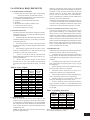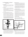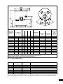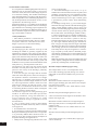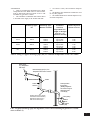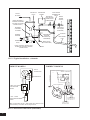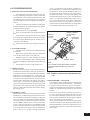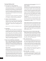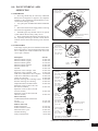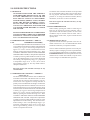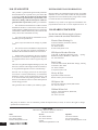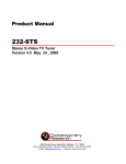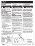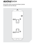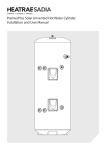
1
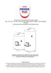
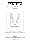
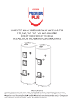
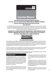
UNVENTED MAINS PRESSURE WATER HEATER 100, 120, 150, 170, 210, 250 AND 300 LITRE DIRECT AND INDIRECT MODELS INSTALLATION AND SERVICING INSTRUCTIONS PACK CONTENTS Premier Plus unvented water heater incorporating immersion heater(s) and thermal controls Factory fitted Temperature/Pressure Relief Valve Cold Water Combination Valve Expansion Vessel Expansion Vessel Mounting Bracket Tundish Motorised Valve (Indirect models only) Compression nuts and olives Immersion heater spanner Installation Instructions 36 00 5803 Issue 7 1 SANTON PREMIER PLUS INSTALLATION AND SERVICING INSTRUCTIONS. PLEASE LEAVE THIS MANUAL WITH THE UNIT FOR FUTURE REFERENCE. CONTENTS SECTION CONTENT 1 INTRODUCTION 2 . . . . . . 2 GENERAL REQUIREMENTS . . . . . . 3 3 INSTALLATION - GENERAL . . . . . . 4 4 INSTALLATION - DIRECT UNITS . . . . . . 9 5 INSTALLATION – INDIRECT UNITS . . . . . 9 6 COMMISSIONING . . . . . . . 11 7 MAINTENANCE . . . . . . . 12 8 FAULT FINDING AND SERVICING . . . . . 13 9 USER INSTRUCTIONS . . . . . . 15 10 GUARANTEE . . . . . . . 16 11 SPARES STOCKISTS . . . . . . . 16 . . PAGE 1.0 INTRODUCTION The Santon Premier Plus is a purpose designed unvented water heater. The unit has a stainless steel inner vessel which ensures an excellent standard of corrosion resistance. The outer casing is a combination of resilient thermoplastic mouldings and plastic coated corrosion proofed steel sheet. All Premiers are insulated with CFC free polyurethane foam to meet the latest European heat loss requirements (see Table 3). The unit is supplied complete with all the necessary safety and control devices needed to allow connection to the cold water mains. All these components are pre-adjusted. This appliance complies with the requirements of the CE marking directive and is WRAS approved to show compliance with Building Regulations (Section G3). The following instructions are offered as a guide to installation which must be carried out by a competent plumbing and electrical installer in accordance with Building Regulation G3, The Building Standards (Scotland) Regulations 1990, or The Building RegulaNOTE: Prior to installation the unit should be stored in an upright position in an area free from excessive damp or humidity. TABLE 1: OPERATIONAL SUMMARY Maximum water supply pressure to PRV Operating pressure of unit Expansion vessel charge pressure Expansion valve setting Nominal storage capacity of units Max. primary working pressure Opening temperature of T&P Relief Valve Opening pressure of T&P Relief Valve 16.0 bar 3.5 bar 3.5 bar 6.0 bar (see Section 2 Table 2) 3.0 bar (indirects only) 90deg C 10 bar IMPORTANT: PLEASE READ ALL THESE INSTRUCTIONS BEFORE COMMENCING INSTALLATION 2 2.0 GENERAL REQUIREMENTS 2.1 COMPONENTS SUPPLIED 1. Premier Plus unvented water heater incorporating immersion heater(s) and thermal controls 2. Factory fitted Temperature/Pressure Relief Valve 3. Cold Water Combination Valve. 4. Expansion Vessel and mounting bracket. 5. Tundish. 6. Motorized Valve (Indirect models only). 7. Compression nuts and olives 8. Immersion heater key spanner 2.2 SITING THE UNIT The Santon Premier Plus must be installed vertically. Although location is not critical, the following points should be considered: • The Santon Premier Plus should be sited to ensure minimum dead leg distances, particularly to the point of most frequent use. • Avoid siting where extreme cold temperatures will be experienced. All exposed pipework should be insulated. • The discharge pipework from the safety valves must have minimum fall of 1:200 from the unit and terminate in a safe and visible position. • Access to associated controls and immersion heaters should be possible to allow for periodic servicing and maintenance. • Ensure that the base chosen for the Santon Premier Plus is level and capable of permanently supporting the weight when full of water (see Table 2). Table 2: Unit weights Type DIRECT Model reference PP100E PP120E PP150E PP170E PP210E PP250E PP300E INDIRECT PP100B PP120B PP150B PP170B PP210B PP250B PP300B Nominal capacity (litres) 100 120 150 170 210 250 300 100 120 150 170 210 250 300 W eight of unit full (kg) 123 145 178 199 246 295 355 125 147 181 203 251 300 360 2.3 WATER SUPPLY Bear in mind that the mains water supply to the property will be supplying both the hot and cold water requirements simultaneously. It is recommended that the maximum water demand is assessed and the water supply checked to ensure this demand can be satisfactorily met. NOTE: A high mains water pressure will not always guarantee high flowrates. Wherever possible the mains supply pipe should be 22mm. We suggest the minimum supply requirements should be 1.5 bar pressure and 20 litres per minute flowrate. However, at these values outlet flowrates may be poor if several outlets are used simultaneously. The higher the available pressure and flowrate the better the system performance. The Santon Premier Plus has an operating pressure of 3.5 bar that is controlled by the Cold Water Combination Valve. The Cold Water Combination Valve can be connected to a maximum mains pressure of 16 bar. 2.4 OUTLET/TERMINAL FITTINGS (TAPS, ETC.) The Santon Premier Plus can be used with most types of terminal fittings. It is advantageous in many mixer showers to have balanced hot and cold water supplies. In these instances a balanced pressure cold water connection should be placed between the Cold Water Combination Valve and the Premier Plus water heater. Outlets situated higher than the Santon Premier Plus will give outlet pressures lower than that at the heater, a 10m height difference will result in a 1 bar pressure reduction at the outlet. 2.5 LIMITATIONS The Premier Plus unvented water heater should not be used in association with any of the following: • Solid fuel boilers or any other boiler in which the energy input is not under effective thermostatic control unless additional and appropriate safety measures are installed. • Ascending spray type bidets or any other class 1 back syphonage risk requiring that a type A air gap be employed. • Steam heating plants unless additional and appropriate safety devices are installed. • Situations where maintenance is likely to be neglected or safety devices tampered with. • Water supplies that have either inadequate pressure or where the supply may be intermittent. • Situations where it is not possible to safely pipe away any discharge from the safety valves. • In areas where the water consistently contains a high proportion of solids, e.g. suspended matter that could block the strainer, unless adequate filtration can be ensured. Table 3: Standing heat losses Nom ina l ca pa city (litres) 100 120 150 170 210 250 300 Sta nding He a t Loss pe r da y pe r ye a r (kW h/24h) (kW h/365d) 1.14 416.1 1.25 456.3 1.45 529.3 1.63 595.0 1.91 697.2 2.22 810.3 2.52 919.8 Based on an ambient air temperature of 20oC and a stored water temperature of 65oC 3 3.0 INSTALLATION – GENERAL (FIGS 3 & 5) 3.1 PIPE FITTINGS All pipe fittings are made via 22mm compression fittings directly to the unit. The fittings are threaded 3/4”BSP male parallel should threaded pipe connections be required. 3.2 COLD FEED A 22mm cold water supply is recommended however, if a 15mm (1/2”) supply exists which provides sufficient flow this may be used (although more flow noise may be experienced). A stopcock or servicing valve should be incorporated into the cold water supply to enable the Santon Premier Plus and its associated controls to be isolated and serviced. 3.3 COLD WATER COMBINATION VALVE (FIG 1) The Cold Water Combination Valve can be connected anywhere on the cold water mains supply prior to the Expansion Vessel (see Fig. 5). The Cold Water Combination Valve is installed as a complete one-piece unit. The valve incorporates the Pressure Reducer, Strainer, Expansion Valve and Check Valve. Ensure that the valve is installed with the direction of flow arrows pointing in the right direction. No other valves should be placed between the Cold Water Combination Valve and the Premier Plus unit. The Expansion Valve connection must not be used for any other purpose. EXPANSION VALVE EXPANSION VALVE OUTLET (15mm) COLD MAINS CONNECTION (22mm) PRESSURE REDUCING VALVE HOUSING 3.5 EXPANSION VESSEL The Expansion Vessel accommodates expansion that results from heating the water inside the unit. The unit is pre-charged at 3.5 bar. The Expansion Vessel must be connected between the Cold Water Combination Valve and the Santon Premier Plus (see Fig. 5). The location of the Expansion Vessel should allow access to recharge the pressure as and when necessary, this can be done using a normal car foot pump. It is recommended that the Expansion Vessel is adequately supported. An Expansion Vessel wall mounting bracket is supplied for this purpose 3.6 SECONDARY CIRCULATION If secondary circulation is required it is recommended that it be connected to the Premier as shown in Fig. 2 via a swept tee joint into the cold feed to the unit. A Swept Tee joint is available as an accessory order code no. 94 970 033. The secondary return pipe should be in 15mm pipe and incorporate a check valve to prevent backflow. A suitable WRAS approved bronze circulation pump will be required. On large systems, due to the increase in system water content, it may be necessary to fit an additional expansion vessel to the secondary circuit. this should be done if the capacity of the secondary circuit exceeds 10 litres. Pipe capacity (copper) 15mm o/d = 0.13 l/m (10 litres = 77m) 22mm o/d = 0.38 l/m (10 litres = 26m) 28mm o/d = 0.55 l/m (10 litres = 18m) Secondary circulation is NOT recommended for direct electric units being used on Off Peak electricity tariffs. COLD� INLET � CONNECTION SECONDARY� RETURN SECONDARY� CIRCULATION� PUMP SWEPT� TEE FIG. 1 Cold Water Combination Valve A suitable draining tap should be installed in the cold water supply to the Premier Plus unit between the Cold Water Combination Valve and the heater at as low a level as possible. It is recommended that the outlet point of the drain pipework be at least 1 metre below the level of the heater (this can be achieved by attaching a hose to the drain tap outlet spigot). 4 CHECK� VALVE OUTLET CONNECTION (22mm) PRESSURE REDUCING VALVE CARTRIDGE (3.5 bar) 3.4 DRAIN TAP COLD� SUPPLY FIG. 2 Secondary circulation connection 3.7 OUTLET The hot water outlet is a 22mm compression fitting located at the top of the cylinder. Hot water distribution pipework should be 22mm pipe with short runs of 15mm pipe to terminal fittings such as sinks and basins. Pipe sizes may vary due to system design. TYPE NOMINAL CAPACITY E = DIRECT (litres) B = INDIRECT DIMENSIONS (mm) A B 306 354 306 354 306 354 306 354 306 354 306 354 306 354 C 493 493 615 615 800 800 925 925 1184 1184 1391 1391 1715 1715 COIL D 784 784 906 906 1090 1090 1216 1216 1474 1474 1726 1726 2040 2040 SURFACE AREA (sq.m) RATING (kW) HEATING TIME RECOVERY DIRECT (mins) (mins) 100 E 100 B 315 0.43 11.8 120 E 120 B 315 0.43 12.5 150 E 150 B 315 0.55 16.4 170 E 170 B 315 0.61 16.0 210 E 210 B 315 0.68 18.3 250 E 250 B 315 0.79 20.0 300 E 300 B 315 0.79 20.0 NOTES: 1. Recovery time based on heating 70% of capacity through 45 deg. C 2. Direct heating times assume use of lower element only 18 22 21 24 26 27 33 99 121 152 173 215 257 310 FIG. 3 General Dimensions M ode l He a ting tim e 70% Re co ve ry 15 to 65de g . C tim e Note s P P 100E P P 150E P P 210E 2 h o u rs 0 8 m i n s 1hour 33m ins 2hours 21m ins 1 h o u r 1 7 m in s 1hour 08m ins 1hour 51m ins 3 k W in p u t 6k W input (us ing both im m ers ion heaters ) 6k W input (us ing both im m ers ion heaters ) P P 100B P P 150B P P 210B 21m ins 24m ins 32m ins 15m ins 20m ins 29m ins Indirec tly heated. P rim ary flow 82deg. C at 15l/m in Indirec tly heated. P rim ary flow 82deg. C at 15l/m in Indirec tly heated. P rim ary flow 82deg. C at 15l/m in Test results obtained by WRc-NSF in accordance with Test Criteria 1-50-220 and 1-50-222 5 3.8 DISCHARGE PIPEWORK It is a requirement of Building Regulation G3 that any discharge from an unvented system is conveyed to where it is visible, but will not cause danger to persons in or about the building. The tundish and discharge pipes should be fitted in accordance with the requirements and guidance notes of Building Regulation G3. The G3 Requirements and Guidance section 3.9 are reproduced in the following sections. Information Sheet No. 33 available from the British Board of Agrement gives further advice on discharge pipe installation. For discharge pipe arrangements not covered by G3 Guidance or BBA Info Sheet No.33 advice should be sought from either your local Building Control Officer or Santon. G3 REQUIREMENT “...there shall be precautions...to ensure that the hot water discharged from safety devices is safely conveyed to where it is visible but will not cause danger to persons in or about the building.” G3 GUIDANCE SECTION 3.9 The discharge pipe (D1) from the vessel up to and including the tundish is generally supplied by the manufacturer of the hot water storage system. Where otherwise, the installation should include the discharge pipe(s) (D1) from the safety device(s). In either case the tundish should be vertical, located in the same space as the unvented hot water storage system and be fitted as close as possible and within 500mm of the safety device e.g. the temperature relief valve. The discharge pipe (D2) from the tundish should terminate in a safe place where there is no risk to persons in the vicinity of the discharge, preferably be of metal and: a. be at least one pipe size larger than the nominal outlet size of the safety device unless its total equivalent hydraulic resistance exceeds that of a straight pipe 9m long i.e. discharge pipes between 9m and 18m equivalent resistance length should be at least two sizes larger than the nominal outlet size of the safety device, between 18 and 27m at least 3 sizes larger , and so on. Bends must be taken into account in calculating the flow resistance. Refer to Diagram 1, Table 1 and the worked example. An alternative approach for sizing discharge pipes would be to follow BS 6700:1987 Specification for design installation, testing and maintenance of services supplying water for domestic use within buildings and their curtilages, Appendix E, section E2 and table 21. b. have a vertical section of pipe at least 300mm long, below the tundish before any elbows or bends in the pipework. c. be installed with a continuous fall. d. have discharges visible at both the tundish and the final point of discharge but where this is not possible or is practically difficult there should be clear visibility at one or other of these locations. Examples of acceptable discharge arrangements are: i. ideally below a fixed grating and above the water 6 seal in a trapped gully. ii. downward discharges at low level; i.e. up to 100mm above external surfaces such as car parks, hard standings, grassed areas etc. are acceptable providing that where children may play or otherwise come into contact with discharges a wire cage or similar guard is positioned to prevent contact, whilst maintaining visibility. iii. discharges at high level; e.g. into a metal hopper and metal down pipe with the end of the discharge pipe clearly visible (tundish visible or not) or onto a roof capable of withstanding high temperature discharges of water and 3m from any plastics guttering system that would collect such discharges (tundish visible). iv. where a single pipe serves a number of discharges, such as in blocks of flats, the number served should be limited to not more than 6 systems so that any instalation discharging can be traced reasonably easily. The single common discharge pipe should be at least one pipe size larger than the largest individual discharge pipe (D2) to be connected. If unvented hot water storage systems are installed where discharges from safety devices may not be apparent i.e. in dwellings occupied by blind, infirm or disabled people, consideration should be given to the installation of an electronically operated device to warn when discharge takes place. Note: The discharge will consist of scalding water and steam. Asphalt, roofing felt and non-metallic rainwater goods may be damaged by such discharges. Worked example of discharge pipe sizing The example below is for a G1/2 temperature relief valve with a discharge pipe (D2) having 4 No. elbows and length of 7m from the tundish to the point of discharge. From Table 4: Maximum resistance allowed for a straight length of 22mm copper discharge pipe (D2) from a G1/2 temperature relief valve is 9.0m. Subtract the resistance for 4 No. 22mm elbows at 0.8m each = 3.2m Therefore the permitted length equates to: 5.8m 5.8m is less than the actual length of 7m therefore calculate the next largest size. Maximum resistance allowed for a straight length of 28mm pipe (D2) from a G1/2 temperature relief valves equates to 18m. Subtract the resistance of 4 No. 28mm elbows at 1.0m each = 4.0m Therefore the maximum permitted length equates to: 14m As the actual length is 7m, a 28mm (D2) copper pipe will be satisfactory. 3.9 WARNINGS • Under no circumstances should the factory fitted Temperature/Pressure Relief Valve be removed other than by authorised Santon personnel. To do so will invalidate any guarantee or claim. • The Cold Water Combination Valve must be fitted to the mains water supply to the Premier Plus unit. Va lve outle t size Minim um size of discha rge pipe D1 G1/2 15mm G3/4 22mm G1 28mm • No control or safety valves should be tampered with. • The discharge pipe should not be blocked or used for any other purpose. • The tundish should not be located adjacent to any electrical components. Minim um size of discha rge pipe D2 from tundish Ma x im um re sista nce a llow e d, e x pre sse d a s a le ngth of stra ight pipe (I.e . no e lbow s or be nds) Re sista nce cre a te d by e a ch e lbow or be nd 22mm 28mm 35mm 28mm 35mm 42mm 35mm 42mm 54mm up to 9m up to 18m up to 27m up to 9m up to 18m up to 27m up to 9m up to 18m up to 27m 0.8m 1.0m 1.4m 1.0m 1.4m 1.7m 1.4m 1.7m 2.3m Table 4 Sizing of copper discharge pipe (D2) for common temperature relief valve outlet Safety device (e.g. Temperature relief valve) Metal discharge pipe (D1) from Temperature relief valve to tundish 500mm maximum Tundish 300mm minimum Discharge pipe (D2) from tundish, with continuous fall. See Building Regulation G3 section 3.9d i-iv, Table 4 and worked example Discharge below fixed grating (Building Regulation G3 section 3.9d gives alternative points of discharge) Fixed grating Trapped gully FIG. 4 Typical discharge pipe arrangement (extract from Building Regulation G3 Guidance section 3.9) 7 T&P RELIEF VALVE TO HOT OUTLETS EXPANSION VESSEL BOOST ELEMENT / CONTROL HOUSING (PP120E TO PP300E MODELS ONLY) COLD WATER COMBINATION VALVE BALANCED MAINS COLD WATER WATER CONNECTION SUPPLY (IF REQUIRED) ELEMENT / CONTROLS HOUSING ISOLATING VALVE (NOT SUPPLIED) PRIMARY RETURN TUNDISH SECONDARY RETURN TAPPING (IF REQUIRED) PRIMARY FLOW DISCHARGE PIPE DRAIN COCK (NOT SUPPLIED) NOTE: PRIMARY HEATING COIL FITTED ON PP100B TO PP300B MODELS ONLY INLET FIG. 5 Typical installation - schematic DIRECT MODELS INDIRECT MODELS EARTH CONNECTION GREEN / YELLOW FUSED (13A) DOUBLE POLE ISOLATING SWITCH THERMOSTAT BLUE BROWN A INDIRECT THERMAL CUT-OUT INDIRECT THERMOSTAT GREEN/YELLOW B 1 1 2 3 2 DIRECT THERMOSTAT 1 2 3 B GREEN/ YELLOW BLUE A 1.5mm 2 3 CORE HOFR SHEATHED CABLE Note: On models fitted with two or three elements each element must be wired individually in accordance with the diagram above. FIG. 6 Electrical Connections (Schematic) 8 BROWN TO INDIRECT SYSTEM CONTROLS JUNCTION BOX - SEE FIGS. 7/8 13 AMP MAINS SUPPLY. 1.5mm2 MIN. CABLE SIZE 4.0 INSTALLATION - DIRECT UNITS 4.1 PLUMBING CONNECTIONS Direct units require the following pipework connections. • Cold water supply to and from inlet controls. • Outlet to hot water draw off points. • Discharge pipework from valve outlets to tundish. 4.2 ELECTRICAL SUPPLY (FIG. 6) 100 litre direct Premier Plus units are fitted with one 3kW immersion heater, all other direct models are fitted with two 3kW immersion heaters as standard. It is recommended that these should be wired via a suitable controller to BSEN 60730. The Premier Plus MUST be earthed. The 250 and 300 litre units have an additional boss which has a blanking plug fitted. An additional immersion heater can be fitted in place of the blanking plug where a higher electrical input is required for faster recovery times, order Part No. 95 970 510 if required. All wiring to the unit must be installed in accordance with the latest IEE Wiring Regulations and the circuit must be protected by a suitable fuse and double pole isolating switch with a contact separation of at least 3mm in both poles. The Live and Neutral connections are made directly onto the combined thermostat and thermal cut-out located under the terminal cover(s) mounted on the side of the unit. The Earth connection should be made to the earth connection located to the side of the immersion heater boss(es). The supply cable must be routed through the cable gland located on the unit casing beneath the terminal housing. DO NOT operate the immersion heaters until the Santon Premier Plus has been filled with water. 4.3 SAFETY DISCONNECT FROM THE MAINS SUPPLY BEFORE REMOVING ANY COVERS. Never attempt to replace the immersion heater(s) other than with the recommended Santon immersion heater(s). DO NOT bypass the thermal cut-out(s) in any circumstances. Ensure the two male spade terminations on the underside of the combined thermostat and thermal cut-out are pushed firmly onto the corresponding terminations on the element plate assembly. In case of difficulty contact Santon service, tel: 5.0 INSTALLATION - INDIRECT UNITS 5.1 PLUMBING CONNECTIONS Indirect units require the following pipework connections. • Cold water supply to and from inlet controls. • Outlet to hot water draw off points. • Discharge pipework from valve outlets to tundish • Connection to the primary circuit. Primary connections are 22mm compression. However, 3/4”BSP parallel threaded fittings can be fitted to the primary coil connections if required. 5.2 ELECTRICAL SUPPLY (FIG. 6) All Indirect units are fitted with a 3kW immersion heater and a combined thermostat and thermal cut-out to control the indirect heating source. The Premier Plus MUST be earthed. All wiring to the unit must be installed in accordance with the latest IEE Wiring Regulations and the supply circuits must be protected by a suitable fuse and double pole isolating switch with a contact separation of at least 3mm in both poles. All connections are made to the terminal block located under the terminal cover mounted on the side of the unit. The supply cable(s) must be routed through the cable grip(s) in the terminal housing. DISCONNECT FROM MAINS SUPPLY BEFORE REMOVING ANY COVERS. DO NOT bypass the thermal cut-outs in any circumstances. Ensure the thermostat and thermal cut-out sensing bulbs are pushed fully into the pockets on the element plate assembly. 5.3 BOILER SELECTION The boiler should have a control thermostat and non self-resetting thermal cut-out and be compatible with unvented storage water heaters. Where use of a boiler without a thermal cut-out is unavoidable a “low head” open vented primary circuit should be used. The Feed and Expansion cistern head above the Premier Plus should not exceed 2.5m. 5.4 PRIMARY CIRCUIT CONTROL The 2 port motorised valve supplied with the Premier Plus indirect units MUST be fitted to the primary flow to the Premier Plus heat exchanger and wired in series with the indirect thermostat and thermal cut-out fitted to the unit. Primary circulation to the Premier Plus heat exchanger must be pumped, gravity circulation WILL NOT WORK. 5.5 SPACE AND HEATING SYSTEMS CONTROLS The controls provided with the Santon Premier Plus will ensure the safe operation of the unit within a central heating system. Other controls will be necessary to control the space heating requirements and times that the system is required to function (see Fig. 7). The Santon Premier Plus is compatible with most heating controls, examples of electrical circuits are shown in Figs. 7 and 8. However, other systems may be suitable, refer to the controls manufacturers’ instructions, supplied with the controls selected, for alternative system wiring schemes. 9 PREMIER PLUS TERMINAL BLOCK Control terminal numbering may differ from those shown. Refer to instructions with controls selected 2 1 3 ZONE VALVE (HTG) G Br 1 Bl O 2 2 L N ZONE VALVE(DHW) (SUPPLIED) ROOM STAT 3 1 GY 3 2 G 2 1 Br Bl GY O 2 3 (SUPPLY) ADOUBLE POLE ISOLATING SWITCH MUST BE INSTALLED IN THE MAINS SUPPLY. ALL EARTH CONNECTIONS BE CONNECTED BACK TO THE MAINS EARTH SUPPLY 1 3 L N 1 2 3 4 5 6 7 8 9 10 1 2 3 4 5 6 7 8 9 10 2 3 HTG ON L DHW ON JUNCTION BOX 3 L N BOILER PROGRAMMER 3 N 2 PUMP FIG. 7 Schematic wiring diagram - Basic 2 x 2 port valve system PREMIER PLUS TERMINAL BLOCK Control terminal numbering may differ from those shown. Refer to instructions with controls selected 2 1 3 3 ZONE VALVE(DHW) (SUPPLIED) ZONE VALVE (HTG) G W Bl O 2 GY G 3 1 Br Bl 2 O GY 3 (SUPPLY) L N ADOUBLE POLE ISOLATING SWITCH MUST BE INSTALLED IN THE MAINS SUPPLY. ALL EARTH CONNECTIONS BE CONNECTED BACK TO THE MAINS EARTH SUPPLY 1 2 L N 1 2 3 4 5 6 7 8 9 10 1 2 3 4 5 6 7 8 9 10 JUNCTION BOX 3 HTG ON DHW ON PROGRAMMER 2 DHW OFF 1 3 2 ROOM STAT 2 L 3 N L 2 N 3 PUMP BOILER FIG. 8 Schematic wiring diagram - 3 port mid position valve system. N.B. Must be used in conjunction with 2 port zone valve suuplied 10 6.0 COMMISSIONING 6.1 FILLING THE UNIT WITH WATER • Check Expansion Vessel pre-charge pressure. The vessel is supplied pre-charged to 3.5 bar to match the control pressure of the Pressure Reducing Valve. The pre-charge pressure is checked using a car tyre gauge by unscrewing the plastic cap opposite the water connection. • Check all connections for tightness including the immersion heater(s). An immersion heater key spanner is supplied for this purpose. • Ensure the drain cock is CLOSED. • Open a hot tap furthest from the Santon Premier Plus. • Open the mains stop cock to fill the unit. When water flows from the tap, allow to run for a few minutes to thoroughly flush through any residue, dirt or swarf, then close the tap. • Open successive hot taps to purge the system of air. 6.2 SYSTEM CHECKS • Check all water connections for leaks and rectify as necessary. • Remove the Pressure Reducing Valve headwork to access the strainer mesh, clean and re-fit. • Manually open, for a few seconds, each relief valve in turn, checking that water is discharged and runs freely through the tundish and out at the discharge point. • Ensure that the valve(s) reseat satisfactorily. 6.3 DIRECT UNITS Switch on electrical supply to the immersion heater(s) and allow the Premier Plus to heat up to normal working temperature (60ºC recommended, approximately graduation 4 on the thermostat). If necessary the temperature can be adjusted by inserting a flat bladed screwdriver in the adjustment knob on top of the immersion heater thermostat and rotating. The adjustment range 1 to 5 represents a temperature range of 10o to 70oC. Check the operation of thermostat(s) and that no water has issued from the Expansion Relief Valve or Temperature/Pressure Relief Valve during the heating cycle. 6.4 INDIRECT UNITS Fill the indirect (primary) circuit following the boiler manufacturer’s commissioning instructions. To ensure the Premier Plus primary heat exchanger is filled, the 2 port motorised valve (supplied) should be manually opened by moving the lever on the motor housing to the FLUSHING ONLY setting. When the primary circuit is full return the lever to the NORMAL USE position. Switch on the boiler, ensure the programmer is set to Domestic Hot Water and allow the Premier Plus to heat up to a normal working temperature (60oC recommended, approximately graduation 4 on the thermostat). If necessary the temperature can be adjusted by inserting a flat bladed screwdriver in the adjustment knob (located on top of the thermostat mounting bracket - see Fig.9) and rotating. The minimum thermostat setting is 10oC. The adjustment range 1 to 5 represents a temperature range of 30o to 70oC. Check the operation of the indirect thermostat and 2 port motorised valve and that no water has issued from the Expansion Relief Valve or Temperature/ PressureRelief Valve during the heating cycle. INDIRECT THERMAL CUT-OUT INDIRECT THERMAL CUT-OUT RESET BUTTON THERMOSTAT ADJUSTMENT INDIRECT THERMOSTAT CABLE CLAMPS TERMINAL BLOCK NOTE: THE HOUSING COVER AND ELEMENT ASSEMBLY HAVE BEEN REMOVED FROM THIS VIEW FOR CLARITY FIG. 9 Indirect thermostat and thermal cut- out 6.5 BENCHMARKTM LOG BOOK On completion of the installation and commissioning of the Premier Plus the BenchmarkTM “Installation, Commissioning and Service Record Log Book” should be completed and signed off by the competent installer or commissioning engineer in the relevant sections. The various system features, location of system controls, user instructions and what to do in the event of a system failure should be explained to the customer. The customer should then countersign the BenchmarkTM log book to accept completion. The log book should be left with the customer along with these instructions. The log book includes sections that should be filled out when any subsequent service or maintenance operation is carried out on the Premier Plus system. 11 7.0 MAINTENANCE 7.1 MAINTENANCE REQUIREMENTS Unvented hot water systems have a continuing maintenance requirement in order to ensure safe working and optimum performance. It is essential that the Relief Valve(s) are periodically inspected and manually opened to ensure no blockage has occurred in the valves or discharge pipework. Similarly cleaning of the strainer element and replacement of the air in the Expansion Vessel will help to prevent possible operational faults. The maintenance checks described below should be performed by a competent installer on a regular basis, e.g. annually to coincide with boiler maintenance. 7.2 SAFETY VALVE OPERATION Manually operate the Temperature/Pressure Relief Valve for a few seconds. Check water is discharged and that it flows freely through the tundish and discharge pipework. Check valve reseats correctly when released. NOTE: Water discharged may be very hot! Repeat the above procedure for the Expansion Valve. 7.3 STRAINER Turn off the cold water supply, boiler and immersion heaters. The lowest hot water tap should then be opened to de-pressurise the system. Remove the Pressure Reducing Valve housing by unscrewing the four securing screws with the Allen key supplied. Pull the Reducing Valve cartridge from the Check Valve housing to access the strainer mesh. Wash any particulate matter from the strainer under clean water. Re-assemble ensuring the seal is correctly fitted, DO NOT use any other type of sealant. Ensure the four securing screws are tightened equally. 7.4 DESCALING IMMERSION HEATER(S) Before removing the immersion heater(s) the unit must be drained. Ensure the water and electrical supply and boiler are OFF before draining. Attach a hosepipe to the drain cock having sufficient length to take water to a suitable discharge point below the level of the unit. Open a hot tap close to the unit and open drain cock to drain unit. Direct models: Open the cover(s) to the immersion heater housing(s) and disconnect wiring from the thermostat mounted on top of the immersion heater(s). Remove the thermostat by carefully pulling outwards from the immersion heater. Unscrew immersion heater backnut(s) and remove immersion heater from the unit. A key spanner is supplied with the Premier Plus unit for easy removal/ tightening of the immersion heater(s). Over time the immersion heater gasket may become stuck to the mating surface. To break the seal insert a round bladed 12 screwdriver into one of the pockets on the immersion heater and gently lever up and down. Indirect models: Open the cover(s) to the immersion heater housing(s) and disconnect wiring from immersion heater(s). Remove thermostat capillary sensors from the pockets on the immersion heater. Unscrew immersion heater backnut(s) and remove immersion heater from the unit. A key spanner is supplied with the Premier Plus unit for easy removal/tightening of the immersion heater(s). Over time the immersion heater gasket may become stuck to the mating surface. To break the seal insert a round bladed screwdriver into one of the pockets on the immersion heater and gently lever up and down. Carefully remove any scale from the surface of the element(s). DO NOT use a sharp implement as damage to the element surface could be caused. Ensure sealing surfaces are clean and seals are undamaged, if in doubt fit a new gasket. Replace immersion heater(s) ensuring the lower (right angled) element hangs vertically downwards towards the base of the unit. It may be helpful to support the immersion heater using a round bladed screwdriver inserted into one of the thermostat pockets whilst the backnut is tightened. Replace thermostat (Direct models) or thermostat capillaries into pocket (Indirect models), rewire, check, close and secure immersion heater housing cover(s). 7.5 EXPANSION VESSEL CHARGE PRESSURE Remove the dust cap on top of the vessel. Check the charge pressure using a tyre pressure gauge. The pressure (with system de-pressurised) should be 3.5bar. If it is lower than the required setting it should be re-charged using a tyre pump (Schrader valve type). DO NOT OVER CHARGE. Re-check the pressure and when correct replace the dust cap. 7.6 RE-COMMISSIONING Check all electrical and plumbing connections are secure. Close the drain cock. With a hot tap open, turn on the cold water supply and allow unit to refill. DO NOT switch on the immersion heater(s) or boiler until the unit is full. When water flows from the hot tap allow to flow for a short while to purge air and flush through any disturbed particles. Close hot tap and then open successive hot taps in system to purge any air. When completely full and purged check system for leaks. The heating source (immersion heater(s) or boiler) can then be switched on. 7.7 BENCHMARKTM LOG BOOK On completion of any maintenance or service of the Premier Plus the BenchmarkTM “Installation, Commissioning and Service Record Log Book” should be filled in to record the actions taken and the date the work was undertaken. 8.0 FAULT FINDING AND SERVICING 8.1 IMPORTANT • Servicing should only be carried by authorised Santon Service Engineers or Agents or by competent installers in the installation and maintenance of unvented water heating systems. • Any spare parts used MUST be authorised Santon parts. • Disconnect the electrical supply before removing any electrical equipment covers. • NEVER bypass any thermal controls or operate system without the necessary safety valves. • Water contained in the Premier unit may be very hot, especially following a thermal control failure. Caution must be taken when drawing water from the unit. 8.2 SPARE PARTS A full range of spare parts are available for the Premier Plus range. Refer to the Technical Data label on the unit to identify the model installed and ensure the correct part is ordered. Description Part no. Immersion heater (lower) 95 606 946 Immersion heater (upper) 95 606 947 Immersion heater gasket 95 611 822 Immersion heater backnut 95 607 869 Immersion heater key 95 607 861 Tundish 95 605 838 Expansion valve cartridge - 6bar 95 605 864 Expansion valve complete - 6bar 95 607 030 Cold water combination valve complete 95 605 022 Cold water combination valve body 95 605 030 Check valve housing 95 605 028 Pressure reducing valve cartridge 3.5bar 95 607 029 Pressure reducing valve housing 95 605 027 Temperature/Pressure Relief Valve 95 605 810 Expansion vessel 12 litre (100, 120 and 150 litre models) 95 607 863 Expansion vessel 18 litre (170 and 210 litre models) 95 607 864 Expansion vessel 25 litre (250 and 300 litre models) 95 607 612 Direct units only Combined thermostat and thermal cut-out 95 612 599 Terminal cover 95 607 836 Indirect units only Indirect thermostat 95 612 697 Indirect Thermal cut-out 95 612 698 Motorised valve 2 port 95 605 819 Terminal housing 95 607 837 4 Way terminal block 95 607 902 Indirect Thermal Cut-out Spare Part No: 95 612 698 Indirect thermostat Spare Part No: 95 612 697 4 Way Terminal Block Spare Part No: 95 612 697 Combined Thermostat & Thermal Cut-out - Direct models Spare Part No: 95 612 599 Cable Gland Expansion Valve Cartridge Spare Part No. 95 605 864 Expansion Valve Complete (6 bar) Spare Part No. 95 607 030 Valve Body Spare Part No. 95 605 030 Check Valve Housing Spare Part No. 95 605 028 Pressure Reducing Valve Housing Spare Part No. 95 605 027 Pressure Reducing Valve Cartridge (3.5 bar) Spare Part No. 95 607 029 Housing Securing Screws (4 off) Strainer Mesh Cold Water Combination Valve Complete Spare Part No. 95 605 022 Cold Water Combination Valve - Exploded view 13 8.3 FAULT FINDING The Fault Finding chart below will enable operational faults to be identified and their possible causes rectified. Any work carried out on the Premier Plus unvented water heater and its associated controls MUST be carried out by a competent installer for unvented water heating systems. In case of doubt contact the Santon Service Department (see contact details at foot of page 16). WARNING DO NOT TAMPER WITH ANY OF THE SAFETY VALVES OR CONTROLS SUPPLIED WITH THE PREMIER PLUS AS THIS WILL INVALIDATE ANY GUARANTEE TABLE 5 Fault Finding Chart FAU L T N o ho t w a te r flo w W a te r fro m h o t t a p s is c old P O S S IB L E C A U S E 1 . M ains s u pp ly o ff 2 . S t ra ine r b lo c k ed 3 . C o ld W a te r C o m bina tio n V a lve in c orre c tly fitt ed 1 . D IR E C T im m e rs ion h ea te r n ot s w itc he d o n 2 . D IR E C T im m e rs ion h ea te r t he rm al c u t -o ut h a s o pe ra t ed 3 . IN D IR E C T p ro gra m m er s et t o C e n tral H e a tin g o nly 4 . IN D IR E C T b oiler n ot w o rk in g 5 . IN D IR E C T t he rm a l c u to ut h a s op e ra te d W a te r dis c h arge s from E x p an s ion V a lve W a te r dis c h arge s from T& P R e lie f V a lve " M ilk y " w a t er 14 6 . IN D IR E C T m o to ris e d va lve no t c on n ec te d c orre c tly 1 . IN TE R M ITTE N TLY E x p an s ion V e s s el c ha rg e p re s s u re h a s re d uc ed be lo w 3 .5 ba r 2 . C O N TIN U A L LY a . C o ld W a te r C o m bina tio n V a lve P re s s u re R ed u c e r n ot w o rk in g c orre c tly REMEDY 1 . C h ec k a nd o p en s t op c o c k 2 . Tu rn o ff w a te r s up p ly . R e m o ve s t ra in er a n d c lea n (s e e S e c tio n 7 .3 ) 3 . C h ec k a nd re fit as re qu ired 1 . C h ec k a nd s w itc h on 2 . C h ec k . R e s e t by pu s h in g b ut to n. 3 . C h ec k . S e t to a D om e s tic H o t W ate r prog ram m e 4 . C h ec k b oiler o pe rat ion . If fa ult is s us p ec te d c o ns ult bo ile r m a nu fa c t ure r's in s t ru c tio n s 5 . C h ec k . R e s e t by pu s h in g b u t to n o n c u t -o u t . C h ec k o pe ra tion o f ind irec t th e rm o s ta t 6 . C h ec k w irin g a nd /o r p lum bin g c on ne c tio n s to m ot oris ed va lve (s e e F ig . 7) 1 . S e e S e c t io n 7.5 fo r re c ha rg in g pro c e d ure a . C h ec k p re s s u re fro m C old W at e r C o m bina tio n V alve . If g re ater th an 3 . 5b ar re pla c e P res s ure R e d uc e r c a rt rid g e b . E x pa n s io n V alve s e at b . R e m ove E x p a ns io n V a lve d am a g ed . c artridg e . C h ec k c on d itio n o f s ea t. If n ec e s s a ry fit n e w E x p an s ion V alve c a rt rid g e. 1 . Th e rm a l c o ntro l failure 1 . S w it c h off p ow er t o N O TE w a te r w ill b e very h ot im m e rs io n h ea te r(s ) an d s hu t d ow n bo ile r. D O N O T t urn o ff w a te r s up p ly . W h e n dis c ha rge s to ps c he c k all t he rm a l c on trols , rep la c e if fa u lty . O x y g e n a te d w a te r W at e r fro m a pres s uris ed s y s te m re le as es ox y g e n b ub bles w he n flo w ing . Th e m ilk in es s w ill d is ap p ea r a fte r a s ho rt w hile. 9.0 USER INSTRUCTIONS 9.1 WARNINGS IF WATER ISSUES FROM THE TEMPERATURE/PRESSURE RELIEF VALVE ON THE SANTON PREMIER PLUS SWITCH OFF ELECTRICAL SUPPLY TO THE IMMERSION HEATER(S) (DIRECT UNITS) OR SHUT DOWN THE BOILER (INDIRECT UNITS). DO NOT TURN OFF ANY WATER SUPPLY. CONTACT A COMPETENT INSTALLER FOR UNVENTED WATER HEATERS TO CHECK THE SYSTEM. DO NOT TAMPER WITH ANY OF THE SAFETY VALVES FITTED TO THE SANTON PREMIER SYSTEM. IF A FAULT IS SUSPECTED CONTACT A COMPETENT INSTALLER. 9.2 TEMPERATURE CONTROLS – DIRECT UNIT IMMERSION HEATER(S) A combined adjustable thermostat and thermal cut-out is provided for each immersion heater. The thermostat is factory set to give a water storage temperature of approx. 55o to 60oC. Access to the thermostat can be made by opening the immersion heater cover - DISCONNECT THE ELECTRICAL SUPPLY BEFORE OPENING THE COVER(S). Temperature adjustment is made by inserting a flat bladed screwdriver in the slot on the adjustment disc on top of the thermostat and rotating. The adjustment range 1 to 5 represents a temperature range of 10o to 70oC (60oC will be approximately position 4). If in any doubt contact a competent electrician. On indirect units an immersion heater is also provided for use should the indirect heat source be shut down for any purpose. The immersion heater control temperature is set using the immersion heater (Direct) thermostat, see section 9.2 above for details.. DO NOT bypass the thermal cut-out(s) in any circumstances. 9.4 FLOW PERFORMANCE When initially opening hot outlets a small surge in flow may be noticed as pressures stabilize. This is quite normal with unvented systems. In some areas cloudiness may be noticed in the hot water. This is due to aeration of the water, is quite normal and will quickly clear. 9.5 OPERATIONAL FAULTS Operational faults and their possible causes are detailed in Section 8.0. It is recommended that faults should be checked by a competent installer. The air volume within the expansion vessel will periodically require recharging to ensure expanded water is accommodated within the unit. A discharge of water INTERMITTENTLY from the Expansion Valve will indicate the air volume has reduced to a point where it can no longer accommodate the expansion. DO NOT bypass the thermal cut-out(s) in any circumstances. 9.3 TEMPERATURE CONTROLS – INDIRECT UNITS (Fig. 9) The Santon Premier Plus Indirect units are fitted with an Indirect Thermostat and Thermal Cut-out. These controls must be wired in series with the 2 port motorised zone valve supplied to interupt the flow of primary water around the heat exchanger coil when the control temperature has been reached. The controls are located within the lower grey terminal housing along with the immersion heater thermostat. The thermostat is factory set to give a water storage temperature of approx. 55o to 60oC. Access to the thermostat can be made by opening the terminal housing cover - DISCONNECT THE ELECTRICAL SUPPLY BEFORE OPENING THE COVER. Temperature adjustment is made by inserting a flat bladed screwdriver in the adjustment knob and rotating. The minimum thermostat setting is 10oC. The adjustment range 1 to 5 represents a temperature range of 30o to 70oC (60oC will be approximately position 4). If in any doubt contact a competent electrician. 15 10.0 GUARANTEE ENVIRONMENTAL INFORMATION This product is guaranteed against faulty materials and manufacture for a period of 25 years from date of purchase (with the exception of the Expansion Vessel which is guaranteed for a period of 5 years and valves, fittings and electrical parts which are guaranteed for a period of 2 years) provided that: • The unit has been installed in accordance with the Installation and Service instructions and all relevant Codes of Practice and Regulations in force at the time of installation, and that all necessary inlet controls and safety valves have been fitted correctly. • Any valves and controls are of the Santon recommended type and specification. • It has only been used for the storage of potable water. • The unit has not been modified or tampered with in any way, and has been regularly maintained as detailed in the Installation and Service instructions. • Within 60 days of installation, the user completes and returns any Certificate of Registration that may be supplied with the unit in order to register the product. The unit is not guaranteed against damage by frost, and the inner container with integral immersion heater(s) is not guaranteed against excessive scale build-up. Periodic loss of charge pressure from the Expansion Vessel is normal (indicated by an intermittent discharge of water from the Expansion Valve) and is not covered under the product guarantee. Refer to Section 7.5 for details on how to restore the Expansion Vessel charge pressure. This guarantee does not affect your statutory rights. Santon products are manufactured from many recyclable materials. At the end of their useful life they should be disposed of at a Local Authority Recycling Centre in order to realise the full environmental benefits. Insulation is by means of an approved CFC/HCFC free polyurethane foam with an ozone depletion factor of 11.0 SPARES STOCKISTS For the fast and efficient supply of spares please contact the stockists listed below. Electric Water Heating Co. 2 Horsecroft Place, Pinnacles, Harlow, Essex, CM19 5BT Tel: 0845 0553811 E-mail: [email protected] SPD Special Product Division Units 9 & 10, Hexagon Buisness Centre, field Road, Hayes, Middlesex, UB4 0TY Tel: 020 86063567 Spring- Parts Center Unit 6 Revolution Park, Buckshaw Village, Chorley, Lancashire, PR7 7DW Tel: 0845 2709801 www.partscenter.co.uk Newey & Eyre Specialist Products Division Please contact your local branch UK Spares Ltd. Tower Lane, Warmley, Bristol, BS30 8XT Tel: 0117 961 6670 William Wilson Ltd. Unit 3A, 780 South Street, Whiteinch, Glasgow, G14 0SY Tel: 0141 434 1530 The policy of Santon is one of continuous product development and, as such, we reserve the right to change specifications without notice. SANTON Hurricane Way, Norwich, Norfolk, NR6 6EA Tel: 01603 420140 Sales Tel: 08700 603263 Fax: 08700 600403 E-mail: [email protected] 16 Service Tel: 08701 600126 Fax: 08701 600181 E-mail: [email protected] Specifier Tel: 01603 420128 Fax: 01603 420229 E-mail: [email protected]