1
www.abb.com
0a_Cop dorso Tmax_XT.indd 1
The data and illustrations are not binding. We reserve
the right to make changes in the course of technical
development of the product.
Copyright 2011 ABB. All rights reserved.
SACE Tmax XT. New low voltage moulded-case circuit-breakers up to 250 A
ABB SACE
A division of ABB S.p.A.
L.V. Breakers
Via Baioni, 35
24123 Bergamo – Italy
Phone: +39 035 395 111
Fax: +39 035 395 306-433
1SDC210033D0202 - 07/2011 (Preliminary) - 4.000 - CAL
Contact us
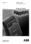
Technical catalogue - Preliminary
SACE Tmax XT
New low voltage moulded-case
circuit-breakers up to 250 A
25/07/11 10:33
Construction Characteristics
1
The SACE Tmax XT Ranges
2
Accessories
3
Characteristic Curves and
Technical Information
4
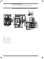
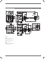
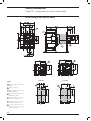
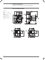
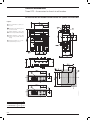
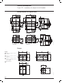
Overall dimensions
5
Wiring Diagrams
6
Ordering codes
7
Glossary
8
1SDC210033D0202
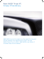
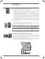
New SACE Tmax XT.
Simply XTraordinary.
ABB SACE is proud to present you the result of a long and
intense research and development project: the new
SACE Tmax XT up to 250A - ABB SACE’s new family of
moulded-case circuit-breakers.
2
Today a highly advanced range of circuit-breakers has been
brought out, with unparalleled versatility of use and able to
solve all installation problems brilliantly.
You can find the new SACE Tmax XT in the three-pole and
four-pole, fixed, plug-in and withdrawable versions, fitted with
the very latest generation thermomagnetic and electronic trip
units, with the possibility of interchangeability. The new SACE
Tmax XT set up a new technological standard and leave
you free to think up and build installations with extraordinary
performances. An extraordinary demonstration of ABB SACE’s
innovation capability.
Extraordinary latest generation electronics. Extraordinary
coverage of all plant requirements. Extraordinary
performances in compact dimensions.
Extraordinary simplicity of installation and putting into service.
Extraordinary range of accessories available.
New SACE Tmax XT. Simply XTraordinary.
3
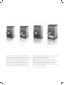
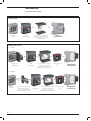
New SACE Tmax XT.
XTraordinary completeness of range.
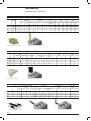
Here are the 4 new SACE Tmax XT frames for you:
– the small XT1 up to 160A;
– the high-performing XT2 up to 160A;
– the reliable XT3 up to 250A;
– the powerful XT4 up to 250A.
4
The new SACE Tmax XT go everywhere and fear no tests
as they are made to respond successfully to all plant
engineering requirements, from the standard ones to the most
technologically advanced ones, thanks to the extraordinary
fullness of their range. A complete offer up to 250A for
distribution, for energy metering, for motor protection,
for generator protection, for oversized neutral, as switchdisconnectors and for any other needs. A new range of
both thermomagnetic and electronic protection trip units,
interchangeable right from the smallest frames. To say nothing
of the new and large number of dedicated accessories
available, even for special applications.
All that remains is for you to choose: XT1 and XT3 for
building standard installations with ABB SACE’s unquestioned
reliability and safety, whereas XT2 and XT4 for building
technologically advanced installations with top of market
performance. New SACE Tmax XT, for any choice, always and
in any case simply extraordinary.
New SACE Tmax XT. XTreme protection.
5
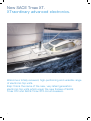
New SACE Tmax XT.
XTraordinary advanced electronics.
Welcome a totally renewed, high-performing and versatile range
of electronic trip units.
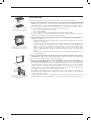
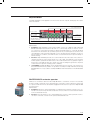
Ekip: this is the name of the new, very latest generation
electronic trip units which equip the new frames of SACE
Tmax XT2 and SACE Tmax XT4 circuit-breakers.
6
The trip units are interchangeable and guarantee absolute
tripping reliability and precision. Apart from the continuous
green LED, which indicates correct operation of the protection
trip unit, all the Ekip trip units also have a LED to signal
intervention of all the protection functions.
To allow the Ekip units to communicate and exchange
information with the other devices, simply insert the Ekip Com
module inside the circuit-breaker, leaving the space inside the
electric panel free.
All the Ekip trip units can be fitted with a vast range of
dedicated accessories. The main ones are:
– the Ekip Display, to be applied onto the front of the
electronic trip unit for simpler setting and for better reading
of information;
– the Ekip LED Meter, a device to be installed on the front of
the trip unit to simplify current readings;
– the Ekip TT, the new trip test unit;
– the Ekip T&P, the extraordinary testing and programming
unit.
Finally, for the first time ground fault protection G is also
available on the 160A frame and an integrated energy
metering function is available on the 250A frame.
Ekip: isn’t all this simply XTraordinary?
New SACE Tmax XT. XTended technology.
7
Construction Characteristics
Index
Construction characteristics ...................................................................................................1/2
Regulations and Reference Standards....................................................................................1/5
Identification of the SACE Tmax XT circuit-breakers ..............................................................1/6
Nomenclature of the trip units and residual current protection devices .................................1/7
1/1
1SDC210033D0202
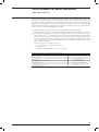
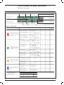
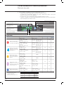
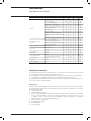
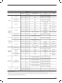
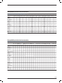
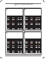
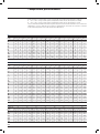
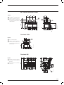
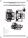
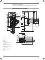
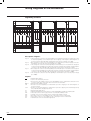
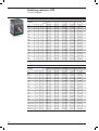
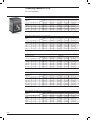
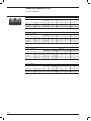
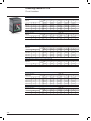
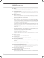
Construction characteristics
XT1
Size(G2.1)
Poles
Rated service voltage, Ue(G2.4)
[A]
[No.]
[V]
[V]
[V]
[kV]
(AC) 50-60Hz
(DC)
Rated insulation voltage, Ui(G2.5)
Rated impulse withstand voltage, Uimp(G2.6)
Versions
Breaking capacities according to IEC 60947-2
Rated ultimate short-circuit breaking capacity, Icu(G2.7)
Icu @ 220-230-240V 50-60Hz (AC)
Icu @ 380V 50-60Hz (AC)
Icu @ 415V 50-60Hz (AC)
Icu @ 440V 50-60Hz (AC)
Icu @ 500V 50-60Hz (AC)
Icu @ 525V 50-60Hz (AC)
Icu @ 690V 50-60Hz (AC)
Icu @ 250V (DC) 2 poles in series
Icu @ 500V (DC) 2 poles in series
Icu @ 500V (DC) 3 poles in series(3)
Rated service short-circuit breaking capacity, Ics(G2.8)
Ics @ 220-230-240V 50-60Hz (AC)
Ics @ 380V 50-60Hz (AC)
Ics @ 415V 50-60Hz (AC)
Ics @ 440V 50-60Hz (AC)
Ics @ 500V 50-60Hz (AC)
Ics @ 525V 50-60Hz (AC)
Ics @ 690V 50-60Hz (AC)
Ics @ 250V (DC) 2 poles in series
Ics @ 500V (DC) 2 poles in series
Ics @ 500V (DC) 3 poles in series(3)
Rated short-circuit making capacity, Icm(G2.10)
Icm @ 220-230-240V 50-60Hz (AC)
Icm @ 380V 50-60Hz (AC)
Icm @ 415V 50-60Hz (AC)
Icm @ 440V 50-60Hz (AC)
Icm @ 500V 50-60Hz (AC)
Icm @ 525V 50-60Hz (AC)
Icm @ 690V 50-60Hz (AC)
Breaking capacities according to NEMA-AB1
@ 240V 50-60Hz (AC)
@ 480V 50-60Hz (AC)
Utilisation Category (IEC 60947-2)
Reference Standard
Isolation behaviour
Mounted on DIN rail
Mechanical life(G2.14)
H
D
(2)
90kA@690V only for XT4 160. Available shortly, please ask ABB SACE
XT1 plug-in In max=125A
1/2
1SDC210033D0202
[kA]
[kA]
[kA]
[kA]
[kA]
[kA]
[kA]
[kA]
[kA]
[kA]
25
18
18
15
8
6
3
18
–
18
40
25
25
25
18
8
4
25
–
25
65
36
36
36
30
22
6
36
–
36
85
50
50
50
36
35
8
50
–
50
100
70
70
65
50
35
10
70
–
70
[kA]
[kA]
[kA]
[kA]
[kA]
[kA]
[kA]
[kA]
[kA]
[kA]
100%
100%
100%
75%
100%
100%
100%
100%
–
100%
100%
100%
100%
50%
50%
100%
100%
100%
–
100%
75% (50)
100%
100%
50%
50%
50%
75%
100%
–
100%
75%
100%
75%
50%
50%
50%
50%
100%
–
100%
75%
75%
50% (37.5)
50%
50%
50%
50%
75%
–
75%
[kA]
[kA]
[kA]
[kA]
[kA]
[kA]
[kA]
52.5
36
36
30
13.6
9.18
4.26
84
52.5
52.5
52.5
36
13.6
5.88
143
75.6
75.6
75.6
63
46.2
9.18
187
105
105
105
75,6
73.5
13.6
220
154
154
143
105
73.5
17
[kA]
[kA]
25
8
40
18
65
30
A
IEC 60947-2
85
36
100
65
S
H
3 poles
[No. Operations]
[No. Hourly operations]
[No. Operations]
[No. Hourly operations]
[mm]
4 poles
[mm]
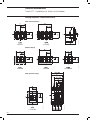
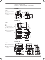
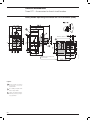
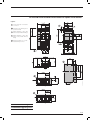
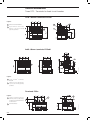
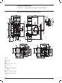
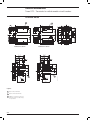
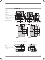
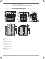
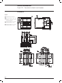
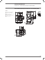
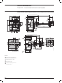
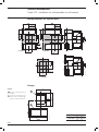
101.6 x 70 x 130
[ms]
[ms]
15
15
W
Total opening time
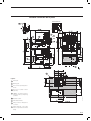
Circuit-breaker with shunt opening release
Circuit-breaker with undervoltage release
Trip units for power distribution
TMD/TMA
TMD
Ekip LS/I
Ekip I
Ekip LSI
Ekip LSIG
Ekip E
Trip units for motor protection
MF/MA
Ekip M-I
Ekip M-LIU
Ekip M-LRIU
Trip units for generator protection
TMG
Ekip G-LS/I
Trip units for oversized Neutral Protection
Ekip N-LS/I
Interchangeable protection trip units
Weight Fixed
Plug in (EF terminals)
Withdrawable (EF terminals)
(1)
C
DIN EN 50022
25000
240
8000
120
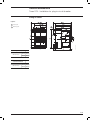
76.2 x 70 x 130
Electrical life @ 415 V (AC)(G2.13)
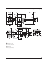
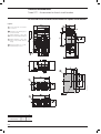
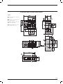
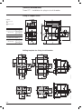
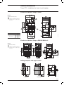
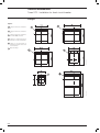
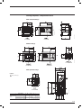
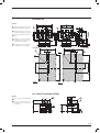
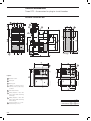
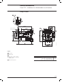
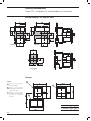
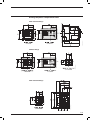
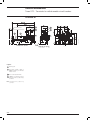
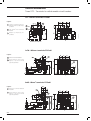
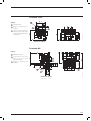
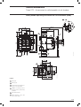
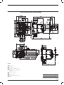
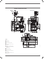
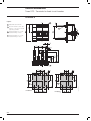
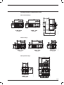
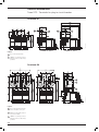
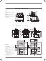
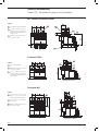
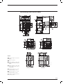
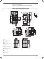
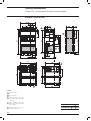
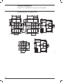
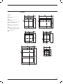
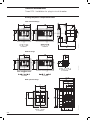
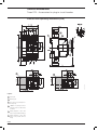
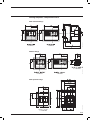
Dimensions - Fixed
(Width x Depth x Height)
B
160
3, 4
690
500
800
8
Fixed, Plug-in (2)
N
Q
3/4 poles
3/4 poles
3/4 poles
[kg]
[kg]
[kg]
(3)
(4)
XT1 500V DC 4 poles in series
XT4 750V DC please ask ABB SACE for availability
1.1 / 1.4
2.21 / 2.82
Q Complete circuit-breaker
V Loose trip unit
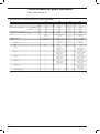
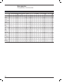
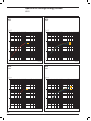
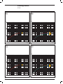
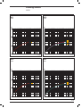
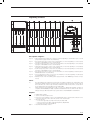
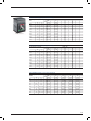
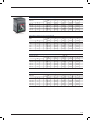
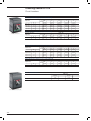
XT2
XT3
XT4
N
160
3, 4
690
500
1000
8
Fixed, Withdrawable, Plug-in
S
H
L
250
3, 4
690
500
800
8
Fixed, Plug-in
N
S
N
160 / 250
3, 4
690
500 (4)
1000
8
Fixed, Withdrawable, Plug-in
S
H
L
65
36
36
36
30
20
10
36
–
36
85
50
50
50
36
25
12
50
–
50
100
70
70
65
50
30
15
70
–
70
150
120
120
100
60
36
18
85
–
85
200
150
150
150
70
50
20
100
–
100
50
36
36
25
20
13
5
36
–
36
85
50
50
40
30
20
6
50
–
50
65
36
36
36
30
20
10
36
36
36
85
50
50
50
36
25
12
50
50
50
100
70
70
65
50
45
15
70
70
70
150
120
120
100
60
50
20
85
85
85
200
150
150
150
70
50
25 (90 (1))
100
100
100
100%
100%
100%
100%
100%
100%
100%
100%
–
100%
100%
100%
100%
100%
100%
100%
100%
100%
–
100%
100%
100%
100%
100%
100%
100%
100%
100%
–
100%
100%
100%
100%
100%
100%
100%
100%
100%
–
100%
100%
100%
100%
100%
100%
100%
75%
100%
–
100%
75%
75%
75%
75%
75%
75%
75%
100%
–
100%
50%
50% (27)
50% (27)
50%
50%
50%
50%
75%
–
75%
100%
100%
100%
100%
100%
100%
100%
100%
100%
100%
100%
100%
100%
100%
100%
100%
100%
100%
100%
100%
100%
100%
100%
100%
100%
100%
100%
100%
100%
100%
100%
100%
100%
100%
100%
100%
100%
100%
100%
100%
100%
100%
100%
100%
100%
100%
75% (20)
100%
100%
100%
143
75.6
75.6
75.6
63
40
17
187
105
105
105
75.6
52.5
24
220
154
154
143
105
63
30
330
264
264
220
132
75.6
36
440
330
330
330
154
105
40
105
75.6
75.6
52.5
40
26
7.65
187
105
105
84
63
40
13.6
143
75.6
75.6
75.6
63
40
17
187
105
105
105
75.6
52.5
24
220
154
154
143
105
94.5
30
330
264
264
220
132
105
40
440
330
330
330
154
105
52.5
65
30
85
36
100
65
A
IEC 60947-2
150
100
200
150
50
25
85
35
65
30
85
36
100
65
A
IEC 60947-2
150
100
200
150
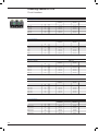
V
A
IEC 60947-2
DIN EN 50022
25000
240
8000
120
90 x 82.5 x 130
DIN EN 50022
25000
240
8000
120
105 x 70 x 150
DIN EN 50022
25000
240
8000
120
105 x 82.5 x 160
120 x 82.5 x 130
140 x 70 x 150
140 x 82.5 x 160
15
15
15
15
15
15
Q
V
Q
Q
Q
Q
Q
Q
Q
Q
Q
Q
Q
Q
Q
V
V
Q
Q
V
Q
Q
V
V
V
V
V
1.2 / 1.6
2.54 / 3.27
3.32 / 4.04
1.7 / 2.1
3.24 / 4.1
2.5 / 3.5
4.19 / 5.52
5 / 6.76
1/3
1SDC210033D0202
Construction characteristics
(Gx.x)
The references in round brackets
technical catalogue.
in the technical catalogue refer to the Glossary in the final charter of the
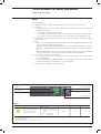
All the moulded-case circuit-breakers in the SACE Tmax XT family are realized in accordance with
the following construction characteristics:
Positive operation
Q
double insulation(G1.5);
Q
positive operation(G1.6);
Q
isolation behaviour(G1.7);
Q
electromagnetic compatibility(G1.8);
Q
tropicalization(G1.9);
Q
impact and vibration resistance(G1.10);
Q
power supply from the top towards the bottom or vice versa;
Q
versatility of the installation. It is possible to mount the circuit-breaker in horizontal, vertical, or
lying down position without any derating of the rated characteristics;
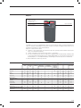
Q
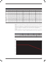
no nominal performance derating for use up to an altitude of 2000m. Above 2000m, the properties of the atmosphere (composition of the air, dielectric strength, cooling power and pressure)
change, having an impact on the main parameters which define the circuit-breaker. The table
below gives the changes to the main performance parameters;
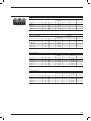
Installation positions
Altitude
2000m
3000m
4000m
5000m
Rated employ voltage, Ue
[V]
690
600
540
470
Rated uninterrupted current
%
100
98
93
90
Q
the SACE Tmax XT circuit-breakers can be used in environments where the temperature is
between -25°C and +70°C and stored in environments where the temperature is between
-40°C and +70°C. To use temperatures other than 40°C, see the “Temperature Performances”
paragraph of the Characteristic Curves and the technical information chapter;
Q
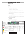
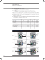
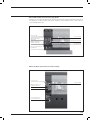
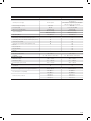
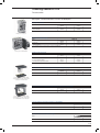
different degrees of protection IP (International Protection)(G 1.11);
1SDC210A20F0001
Circuit-breaker
With
front
Protection degrees
Without
front(1)
With Front
for lever
-FLD-
With
rotary
Handles
With transmitted With high
With low
rotary handle and
terminal
terminal
accessory IP54 covers HTC covers LTC
A
IP40
IP20
IP40
IP40
IP54
IP40
IP40
B
IP20
IP20
IP20
IP20
IP20
IP40
IP40
C
NC
NC
NC
NC
NC
IP40
IP30
(1)
During the installation of electrical accessories
NC Not classifiable
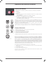
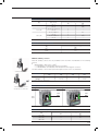
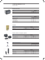
Accessories
On Front
Q
Test pushbutton
1/4
1SDC210033D0202
Motor operator
MOD, MOE
or MOE-E
Residual
current
devices
Residual current
from switchboard
RCQ020
Automatic Transfer
Switch ATS021
and ATS022
IP30
IP40
IP41
IP40
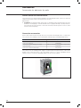
all the circuit-breakers in the XT family are fitted with a test pushbutton which allows the release
test to be done. This test must be carried out with the circuit-breaker closed and with no
current.
Regulations and Reference Standards
Conformity with Standards
The SACE Tmax XT circuit-breakers and their accessories are constructed in conformity with:
Q
Standard(G6.1):
– IEC 60947-2;
Q
Directives(G6.2):
– EC “Low Voltage Directive” (LVD) N° 2006/95/EC (in replacement of 73/23/EEC and subsequent amendments);
– EC “Electromagnetic Compatibility Directive” (EMC) 2004/108/CE;
Q
Naval Registers(G6.3) (ask ABB SACE for the versions available):
– Lloyd’s Register of Shipping, Germanischer Lloyd, Bureau Veritas, Rina, Det Norske Veritas,
Russian Maritime Register of Shipping, ABS.
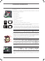
Hologram
Certification of conformity with the product Standards is carried out in the ABB SACE tests laboratory
(accredited by SINAL) in respect of the EN 45011 European Standard, by the Italian certification
body ACAE (Association for Certification of Electrical Apparatus), member of the European LOVAG
organisation (Low Voltage Agreement Group) and by the Swedish certification body SEMKO
belonging to the international IECEE organisation.
The SACE Tmax XT series has a hologram on the front, obtained using special anti-forgery techniques, a guarantee of the quality and genuineness of the circuit-breaker as an ABB SACE product.
Company Quality System
The ABB SACE Quality System conforms with the following Standards:
Q
Q
Q
Q
ISO 9001 international Standard;
EN ISO 9001 (equivalent) European Standards;
UNI EN ISO 9001 (equivalent) Italian Standards;
IRIS International Railway Industry Standard.
The ABB SACE Quality System attained its first certification with the RINA certification body in 1990.
Environmental Management System, Social Responsibility and Ethics
Naval Registers
Attention to protection of the environment is a priory commitment for ABB SACE. Confirmation of
this is the realisation of an Environmental Management System certified by RINA (ABB SACE was
the first industry in the electromechanical sector in Italy to obtain this recognition) in conformity
with the International ISO14001 Standard. In 1999 the Environmental Management System was
integrated with the Occupational Health and Safety Management System according to the OHSAS
18001 Standard and later, in 2005, with the SA 8000 (Social Accountability 8000) Standard, committing itself to respect of business ethics and working conditions.
The commitment to environmental protection becomes concrete through:
Q selection of materials, processes and packaging which optimise the true environmental impact
of the product;
Q use of recyclable materials;
Q voluntary respect of the RoHS directive(G6.4).
ISO 14001, 18001 and SA8000 recognitions togheter with ISO 9001 made it possible to obtain
RINA BEST FOUR CERTIFICATION.
1/5
1SDC210033D0202
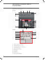
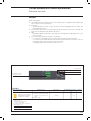
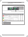
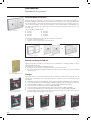
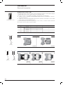
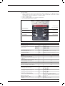
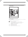
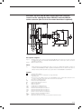
Identification of the SACE Tmax XT
circuit-breakers
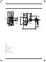
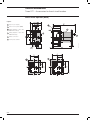
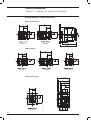
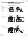
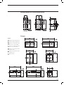
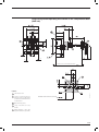
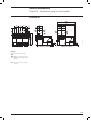
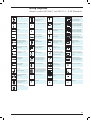
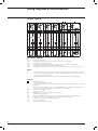
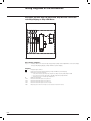
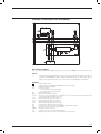
The characteristics of the circuit-breaker are given on the rating nameplate on the front of the circuitbreaker, and on the side rating plate.
Front label
1
7
4
3
10
7
6
5
14
11
1
9
15
13
12
8
2
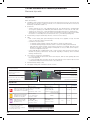
Side label
1
7
7
6
5
14
15
6
10
1
2
3
4
5
6
7
8
9
10
11
12
13
14
15
(*)
1/6
1SDC210033D0202
Name of the circuit-breaker and performance level(*)
In: rated current of the circuit-breaker(*)
Uimp: rated impulse withstand voltage(*)
Ui: insulation voltage(*)
Ics rated short-circuit duty breaking capacity(*)
Icu: rated ultimate short-circuit breaking capacity(*)
Ue: rated service voltage(*)
Symbol of isolation behaviour(*)
Reference Standard IEC 60947-2(*)
Serial number
Anti-forgery logo
Test pushbutton
CE marking
Utilisation Category
Reference Standard NEMA-AB1
In compliance with the IEC 60947-2 Standard
9
3
4
13
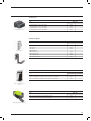
Nomenclature of the trip units and
residual current protection devices
The tables below give details of the logic with which each thermomagnetic trip units, electronic trip
units and residual current devices has been named.
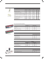
Magnetic trip units
Family Name
Protection
M: magnetic
+
F: with fixed threshold
A: with adjustable threshold
Family Name
Protection
TM: thermomagnetic
+
A: with adjustable thermal and magnetic threshold
D: with adjustable thermal and fixed magnetic threshold
G: with adjustable thermal and fixed magnetic threshold
(for generator protection)
Thermomagnetic trip units
Example:
Q
Q
Q
MA: magnetic only trip unit, with adjustable protection threshold;
TMD: thermomagnetic trip unit, with adjustable thermal and fixed magnetic protection threshold;
TMG: thermomagnetic trip unit, with adjustable thermal and fixed magnetic protection threshold, specifically
for protection of generators.
Electronic trip units
Family Name
+
Ekip
(1)
Application
Protection
Circuit-breaker (1)
….: Distribution
M: Motor protection
G: Generator protection
N: Neutral
E: Energy measurements
I
LS/I
LSI
LSIG
LIU
LRIU
XT2
XT4
+
Circuit-breaker has to be defined only with loose release.
Example:
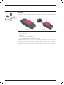
Q Ekip LS/I: electronic trip unit for distribution networks protection, with “L” against overload and as an alternative “S” protection function against delay short circuit or “I” protection function against instantaneous short
circuit;
Q Ekip M-LRIU: electronic trip unit for motors protection, with LRIU protection functions;
Q Ekip N-LS/I XT2: loose electronic trip unit for the neutral protection, with “L” against overload and as an alternative “S” protection function against delay short circuit or “I” protection function against instantaneous short
circuit.
Residual Current Protection Devices
Family Name
Typology
RC
Inst: instantaneous type “A”
Sel: selective type “A”
Sel 200: selective type “A” reduced to 200mm
B Type: selective type “B”
+
Example:
Q RC Inst: residual current protection device with instantaneous timing;
Q RC Sel 200: residual current protection device with adjustable time trip, reduced to 200mm;
Q RC B type: residual current protection device “B” type.
1/7
1SDC210033D0202
The SACE Tmax XT Ranges
Index
The SACE Tmax XT family ranges .......................................................................................2/2
Circuit-breakers for power distribution
Main characteristics ................................................................................................................2/3
Thermomagnetic trip units ......................................................................................................2/5
Electronic trip units..................................................................................................................2/7
Circuit-breakers for motors protection
Main characteristics ..............................................................................................................2/14
Magnetic trip units.................................................................................................................2/16
Electronic trip units................................................................................................................2/17
Circuit-breakers for generator protection
Main characteristics ..............................................................................................................2/21
Circuit-breakers for oversized neutral protection
Main characteristics ..............................................................................................................2/25
Switch-disconnectors
Main characteristics ..............................................................................................................2/27
Special applications
400Hz installations ................................................................................................................2/29
Communication system.........................................................................................................2/30
2/1
1SDC210033D0202
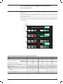
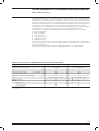
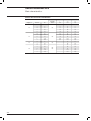
The SACE Tmax XT family ranges
The SACE Tmax XT moulded-case circuit-breaker family complies with different installation requirements. Circuit-breakers are available with trip units dedicated to different applications, such as
power distribution, generator protection, motor protection and oversized neutral protection. Some
of these circuit-breakers can also be used in communication systems and plants that function at
400Hz. Switch-disconnectors are also available.
In = Rated uninterrupted current(G2.2)
XT1 160
XT2 160
XT3 250
XT4 250
Power distribution
Thermomagnetic trip units
TMD
16…160
TMD/TMA
63…250
1.6…160
16…250
Ekip LS/I
10…160
40…250
Ekip I
10…160
40…250
Ekip LSI
10…160
40…250
Ekip LSIG
10…160
40…250
Electronic trip units
Ekip E-LSIG
40…250
Motor protection
Magnetic trip units
1…100(1)
MF/MA
100…200 (1)
10…200 (1)
Electronic trip units
Ekip M-I
20…100(1)
Ekip M-LIU
25…100 (1)
40…160 (1)
(1)
40…200 (1)
Ekip M-LRIU
25…100
Generator Protection
Thermomagnetic trip units
TMG
16…160
63…250
Electronic trip units
Ekip G-LSI
10…160
40…250
10…100(2)
40…160 (2)
Oversized Neutral Protection 160%
Electronic trip units
Ekip N-LS/I
Switch-disconnectors
Q
Q
Q
Q
Q
Special applications
400Hz
Communication
(1)
(2)
Only 3 poles version
Only 4 poles version
2/2
1SDC210033D0202
Q
Q
Q
Q
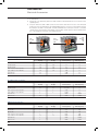
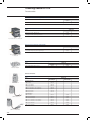
Circuit-breakers for power distribution
Main characteristics
SACE Tmax XT moulded-case circuit-breakers are the ideal solution for all distribution levels, from
the main low voltage switchboard to the subswitchboards in the installation. They feature high
specific let-through current peak and energy limiting characteristics that allow the circuits and
equipment on the load side to be sized in an optimum way. SACE Tmax XT circuit-breakers with
thermomagnetic and electronic trip units protect against overloads, short-circuits, earth faults and
indirect contacts in low voltage distribution networks.
The SACE Tmax XT family of moulded-case circuit-breakers can be equipped with:
thermomagnetic trip units(G3.2), for direct and alternating current network protection, using the
physical properties of a bimetal and an electromagnet to detect the overloads and short-circuits;
Q electronic trip units(G3.4), for alternating current network protection. Releases with microprocessor technology obtain protection functions that make the operations extremely reliable and
accurate. The power required for operating them correctly is supplied straight from the current
sensors of the releases. This ensures that they trip even in single-phase conditions and on a level
with the minimum setting.
The electronic protection trip unit consists of:
Q
– 3 or 4 current sensors (current transformers);
– a protection unit;
– an opening solenoid (built into the electronic trip unit).
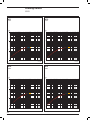
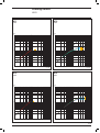
Characteristics of Electronic trip units SACE Tmax XT
Operating temperature
Relative humidity
Self-supplied
Auxiliary supply (where applicable)
Operating frequency
Electromagnetic compatibility
(1)
(2)
-25°C…+70°C
98%
0.2xIn (single phase)(1) (2)
24V DC ± 20%
45…66Hz or 360…440Hz
IEC 60947-2 Annex F
0.32 x In for Ekip N-LS/I
For 10A: 0.4In
2/3
1SDC210033D0202
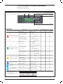
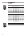
Circuit-breakers for power distribution
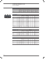
Main characteristics
Characteristics of circuit-breakers for power distribution
Size(G2.1)
[A]
Poles
Rated service voltage, Ue(G2.4)
XT3
XT4
160
250
160/250
3, 4
[Nr.]
3, 4
3, 4
3, 4
[V]
690
690
690
690
(DC)
[V]
500
500
500
500
[V]
800
1000
800
1000
[kV]
8
8
8
8
Fixed,
Plug-in
Fixed, Withdrawable,
Plug-in
Fixed,
Plug-in
Fixed, Withdrawable,
Plug-in
Rated impulse withstand voltage, Uimp(G2.6)
Versions
Trip units
XT2
160
(AC) 50-60Hz
Rated insulation voltage, Ui(G2.5)
Breaking capacities
XT1
B
C
N
H
N
S
H
L
V
Thermomagnetic,
Electronic
N
S
Thermomagnetic
Q
TMD/TMA
TMD
S
Thermomagnetic
Q
N
S
H
L
V
Thermomagnetic,
Electronic
Q
Q
Ekip LS/I
Q
In = 10A, 25A, 63A,
100A, 160A
Q
In = 40A, 63A, 100A,
160A, 250A
Ekip I
Q
In = 10A, 25A, 63A,
100A, 160A
Q
In = 40A, 63A, 100A,
160A, 250A
Ekip LSI
Q
In = 10A, 25A, 63A,
100A, 160A
Q
In = 40A, 63A, 100A,
160A, 250A
Ekip LSIG
Q
In = 10A, 25A, 63A,
100A, 160A
Q
In = 40A, 63A, 100A,
160A, 250A
Q
In = 40A, 63A, 100A,
160A, 250A
Ekip E-LSIG
Interchangeability
Q Complete circuit-breaker
2/4
1SDC210033D0202
Q
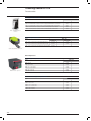
Q
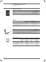
Circuit-breakers for power distribution
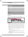
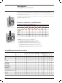
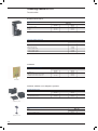
Thermomagnetic trip units
TMD
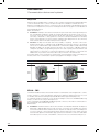
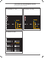
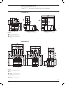
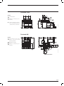
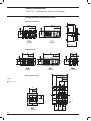
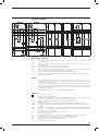
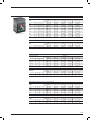
Main characteristics:
Q
available for XT1 and XT3 in the three-pole and four-pole versions;
Q
protections:
– against overload (L): adjustable protection threshold from 0.7...1xIn, with inverse long-time
trip curve;
– against instantaneous short-circuits (I): fixed 10xIn protection threshold, with instantaneous
trip curve;
Q
100% neutral protection in four-pole circuit-breakers. 50% neutral protection is only available for
In*125A;
Q
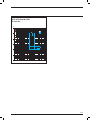
the thermal protection setting is made by turning the relative cursor on the front of the release.
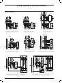
Example with XT3 250A
Rotary switch for thermal
protection setting
XT1
TMD
Breaking capacity
I 1 = 0.7…1xIn
I 3 = 10xIn
B
B
B,C
B,C,N
B,C,N
ALL
ALL
ALL
ALL
ALL
ALL
In [A]
16
20
25
32
40
50
63
80
100
125
160
Neutral [A] - 100%
16
20
25
32
40
50
63
80
100
125
160
Neutral [A] - 50%
–
–
–
–
–
–
–
–
–
80
100
I3 [A]
450
450
450
450
450
500
630
800
1000
1250
1600
Neutral [A] - 100%
450
450
450
450
450
500
630
800
1000
1250
1600
Neutral [A] - 50%
–
–
–
–
–
–
–
–
–
800
1000
XT3
TMD
I 1 = 0.7…1xIn
I 3 = 10xIn
In [A]
63
80
100
125
160
200
250
Neutral [A] - 100%
63
80
100
125
160
200
250
Neutral [A] - 50%
–
–
–
80
100
125
160
I3 [A]
630
800
1000
1250
1600
2000
2500
Neutral [A] - 100%
630
800
1000
1250
1600
2000
2500
Neutral [A] - 50%
–
–
–
800
1000
1250
1600
2/5
1SDC210033D0202
Circuit-breakers for power distribution
Thermomagnetic trip units
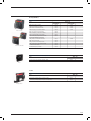
TMD/TMA
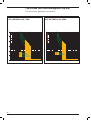
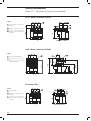
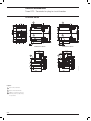
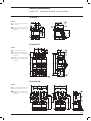
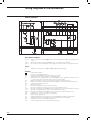
Main characteristics:
Q
available for XT2 and XT4 in the three-pole and four-pole versions;
Q
protections:
– against overload (L): adjustable protection threshold from 0.7...1xIn, with inverse long time
trip curve;
– against instantaneous short-circuit (I):
- fixed protection threshold for In)32A,
- adjustable threshold beteewn 8…10xIn for 40A,
- adjustable threshold beteewn 6…10xIn for 50A,
- adjustable threshold beteewn 5…10xIn for In*63A;
Q
100% neutral protection in four-pole circuit-breakers. 50% neutral protection is only available for
In*125A;
Q
the thermal and magnetic protection settings are made by turning the relative cursors on the
front of the release.
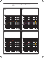
Example with XT4 250A
Rotary switch for magnetic
protection setting
Rotary switch for thermal
protection setting
XT2
TMD/TMA
In [A]
1.6(1) 2(1) 2.5(1) 3.2(1) 4(1) 5(1) 6.3(1) 8(1) 10(1) 12.5(1) 16
Neutral [A] - 100% 1.6
I1 = 0.7…1xIn Neutral [A] - 50%
TMD
2
2.5
3.2
4
5
6.3
8
–
–
–
–
–
–
–
–
16
20
25
32
40 50
63
10 12.5 16
–
–
–
20
25
32
40
50
63
80
100
125
160
20
25
32
40
50
63
80
100
125
160
–
–
–
–
–
–
–
–
80
100
80 100 125 300 300 300 320
TMA
(1)
300… 300… 300… 400… 500… 625… 800…
400 500 630 800 1000 1250 1600
Neutral [A] - 100%
16
20
25
32
Neutral [A] - 50%
–
–
–
–
40 50
–
–
63
–
80 100 125 300 300 300 320 300… 300… 300… 400… 500… 625… 800…
400 500 630 800 1000 1250 1600
–
–
–
–
–
–
–
–
–
–
–
–
400… 1000…
800 2000
Available only as complete circuit-breaker
XT4
TMD/TMA
I1 = 0.7…1xIn
In [A]
16
20
25
32
40
50
63
80
100
125
160
200
225
250
Neutral [A] - 100%
16
20
25
32
40
50
63
80
100
125
160
200
225
250
–
–
–
–
–
80
100
125
125
160
300…
400
300…
500
315…
630
400…
800
500…
1000
625…
1250
800…
1600
1000… 1125… 1250…
2000
2250
2500
Neutral [A] - 50%
TMD
–
–
–
–
300
300
300
320
TMA
2/6
1SDC210033D0202
Neutral [A] - 100%
300
300
300
320
300…
400
300…
500
315…
630
400…
800
500…
1000
625…
1250
800…
1600
1000… 1125… 1250…
2000
2250
2500
Neutral [A] - 50%
–
–
–
–
–
–
–
–
–
315…
630
500…
1000
625…
1250
625…
1250
500…
1000
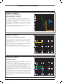
Circuit-breakers for power distribution
Electronic trip units
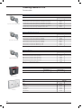
Ekip I
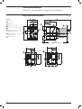
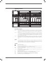
Main characteristics:
Q
usable with the XT2 and XT4 circuit-breaker in the three-pole and four-pole versions;
Q
protections:
– against instantaneous short-circuit (I): adjustable protection threshold from 1...10xIn, with
instantaneous trip curve;
– of the neutral in four-pole circuit-breakers:
- for In*100A in the OFF or ON positions, 50% and 100% of the phases can be selected;
- for In<100A, neutral protection is fixed at 100% of the phases and disableded by user;
Q
manual setting using the relative dip-switches, which allow the settings to be made even when
the trip unit is off;
Q
LED:
– LED lit with a steady green light indicating that the trip unit is supplied correctly. The LED
comes on when the current exceeds 0.2xIn;
– LED with a steady red light, indicating that protection I has tripped; red LED light on connecting Ekip TT or Ekip T&P accessories after circuit-breaker opening for “I protection” intervention;
– Ekip I is equipped with a trip coil disconnection protection device that detects whether the
opening solenoid has disconnected. Signalling is made by the red LED flashing;
Q
test connector on the front of the trip unit;
– to connect the Ekip TT trip test unit, which allows trip test, LED test and signalling about
latest trip happened;
– to connect the Ekip T&P unit, which allows the measurements to be read, the trip test to be
conducted and the I protection function test to be carried out;
Q
self-supply from a minimum current of 0.2xIn up.
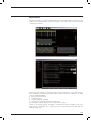
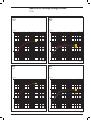
Power-on LED
I protection LED
Test Connector
Dip switch for I protection
function setting
Slot for lead seal
Ekip I
Protection function
Against short-circuits with
adjustable treshold and
instantaneous trip time
(1)
Trip threshold
Manual setting:
I 3= 1, 1.5, 2, 2.5, 3, 3.5, 4.5,
5.5, 6.5, 7, 7.5, 8, 8.5, 9,
10xIn
Trip curve (1)
Excludability
Relation
)20ms
Yes
t=k
Tolerance: ±20% I>4In
±10% I)4In
Tollerances in case of:
– self-powered trip unit at full power;
– 2 or 3 phase power supply.
In conditions other than those considered, the trip time is )60ms.
2/7
1SDC210033D0202
Circuit-breakers for power distribution
Electronic trip units
Ekip LS/I
Main characteristics:
Q available for XT2 and XT4 in the three-pole and four-pole versions;
Q protections:
– against overload (L): 0.4...1xIn adjustable protection threshold, with adjustable time trip curve;
– against short-circuit with delay (S): 1...10xIn adjustable protection threshold, with adjustable
time trip curve (as an alternative to I protection);
– against instantaneous short-circuit (I): 1...10xIn adjustable protection threshold, with instantaneous trip curve (as an alternative to S protection);
– of the neutral in four-pole circuit-breakers:
- for In *100A can be selected in the OFF or ON positions, 50%, 100% of the phases;
- for In <100A, neutral protection is fixed at 100% of the phases and disableded by user;
Q manual setting using the relative dip-switches on the front of the trip unit, which allow the settings to be made even when the trip unit is off;
Q LED:
– LED with steady green light indicating that the trip unit is supplied correctly. The LED comes
on when the current exceeds 0.2xIn;
– red LED for each protection:
- L: LED with steady red light, indicates pre-alarm for current exceeding 0.9xI1;
- L: LED with flashing red light, indicates alarm for current exceeding setted threshold;
- LS/I: LED with steady red light, shows that the protection has tripped. After the circuitbreaker has opened, connect the Ekip TT or Ekip T&P accessory to find out which protection function tripped the trip unit;
– Ekip LS/I is equipped with a trip coil disconnection detection device that detects whether the
opening solenoid has disconnected. Signalling is made by all the red LEDs flashing simultaneously;
Q test connector on the front of the release:
– to connect the Ekip TT trip test unit, which allows trip test, LED test and signalling about
latest trip happened;
– to connect the Ekip T&P unit, which allows the measurements to be read, the trip test to be
conducted and the protection functions test to be carried out;
Q thermal memory which can be activated by Ekip T&P;
Q self-supply from 0.2xIn minimum current up.
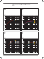
Dip switch for the trip curve selection
Power-on LED
L, S, I protection LED
Test Connector
Slot for lead seal
Dip switch for the selection
between S protection function
or I protection function
Dip switch for LS/I
protection function setting
Ekip LS/I
Protection function
Against overloads with
long inverse time delay trip
according to IEC 60947-2
Standard
Against short-circuits with
indipendend time delay
(t=k)
Against short-circuits with
adjustable treshold and
instantaneous trip time
(1)
Tollerances in case of:
– self-powered trip unit at full power;
– 2 or 3 phase power supply.
In conditions other than those considered, the
following tollerance hold:
2/8
1SDC210033D0202
Trip threshold
Trip curve(1)
Manual setting:
I1= 0.4...1xIn step 0.04
Manual setting:
t1= 12-36s at I=3xI1
Tolerance: trip between
1.05…1.3 I1 (IEC 60947-2)
Tolerance: ±10% up to 4xIn
±20% from 4xIn
Manual setting:
t2= 0.1-0.2s
I2= 1-1.5-2-2.5-3-3.5-4.5-5.5- Tolerance: ±15%
6.5-7-7.5-8-8.5-9-10xIn
Excludability Relation Thermal memory
–
t = k/l2
Yes
Yes
t=k
–
Yes
t=k
–
Tolerance: ±10%
Manual setting:
I3= 1-1.5-2-2.5-3-3.5-4.5-5.56.5-7-7.5-8-8.5-9-10xIn
)20ms
Tolerance: ±10%
Protection
L
S
I
Trip threshold
release between 1.05 and 1.3 x I1
±10%
±15%
Trip time
±20%
±20%
)60ms
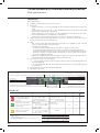
Ekip LSI and Ekip LSIG
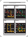
Main characteristics:
Q
available for XT2 and XT4 in three-pole and four-pole versions;
Q
protections:
– against overloads (L): 0.4...1xIn adjustable protection threshold, with adjustable time trip
curve;
– against short-circuits with delay (S): 1...10xIn adjustable protection threshold, with adjustable
time trip curve (short inverse time (t=k2) or indipendent time (t=k));
– against instantaneous short-circuits (I): 1...10xIn adjustable protection threshold, with instantaneous trip curve;
– against earth faults (G): 0.2...1xIn adjustable protection threshold, with indipendent time trip
curve;
– of the neutral in four-pole circuit-breakers:
- for In*100A can be selected in OFF or ON, 50%, 100% of phases;
- for In<100A neutral protection is fixed on 100% of phases and disableded by user;
Q
setting:
– manual setting using the relative dip-switches on the front of the trip unit, which allow the
settings to be made even when the trip unit is off;
– electronic setting, made both locally using the Ekip T&P or Ekip Display accessory and via
remote control, by means of the Ekip Com unit;
Q
LED:
– LED on with steady green light indicating that the trip unit is supplied correctly. The LED
comes on when the current exceeds 0.2xIn;
– red LED for each protection:
- L: LED with steady red light, indicates pre-alarm for current exceeding 0.9xI1;
- L: LED with flashing red light, indicates alarm for current exceeding setted threshold;
- LSIG: LED with steady red light, shows that the protection has tripped. After the circuitbreaker has opened, connect the Ekip TT or Ekip T&P accessory to find out which protection function tripped the trip unit;
– the trip unit is equipped with a device that detects the eventual opening solenoid disconnection thanks to the simultaneous blinking of all the LED;
Q
test connector on the front of the release:
– to connect the Ekip TT trip test unit, which allows trip test, LED test and signalling about the
latest trip happened;
– to connect the Ekip T&P unit, which allows the measurements to be read, the trip test to be
conducted, the protection functions test to be carried out, electronic setting of the protection
functions of the trip unit and of the communication parameters;
Q
thermal memory which can be activated by Ekip T&P or Ekip Display;
Q
self-supply from a minimum current of 0.2xIn up;
Q
the three-pole version can be accessorized with external neutral;
Q
with the addition of the Ekip Com in the circuit-breaker, you can:
– acquire and transmit a wide range of information via remote control;
– accomplish the circuit-breaker opening and closing commands by means of the motor operator in the electronic version (MOE-E);
– know the state of the circuit-breaker (open/closed/trip) via remote control;
– setting the configuration and programming the unit, such as the current thresholds and the
protection function curves.
2/9
1SDC210033D0202
Circuit-breakers for power distribution
Electronic trip units
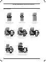
Power-on LED
L, S, I, G protection LED
Slot for lead seal
Test connector
Dip switch for the S trip
curves selection
Selection for manual or
electronic setting
Selection for remote
or local setting
Dip switch for LSIG
protection function setting
Dip switch for the trip curve selection
Ekip LSI – Ekip LSIG
Protection function
Trip curve(1)
Trip threshold
Manual setting:
I1= 0.4...1xIn step 0.02
Tolerance: trip between
1.05…1.3 I1 (IEC 60947-2)
Against overloads with
long inverse time delay trip
according to IEC 60947-2 Electronic setting:
Standard
I1= 0.4...1xIn step 0.01
Tolerance: trip between
1.05…1.3 I1 (IEC 60947-2)
Excludability
Relation
Thermal
memory
–
t = k/l2
Yes
–
t = k/l2
Yes
Yes
t = k/l2
–
Yes
t = k/l2
–
Yes
t=k
–
Yes
t=k
–
)40ms
Yes
t=k
–
)40ms
Yes
t=k
–
Yes
I 2t = k
–
Yes
I 2t = k
–
Manual setting:
t1 = 3-12-36-60s
at I=3xI1
Tolerance: ±10% up to 4xIn
±20% from 4xIn
Electronic setting:
t1 = 3...60s
at I=3xI1 step 0.5
Tolerance: ±10% up to 4xIn
±20% from 4xIn
Manual setting:
Manual setting:
I2 = 1-1.5-2-2.5-3-3.5-4.5-5.5- t2= 0.05-0.10-0.20-0.40s
6.5-7-7.5-8-8.5-9-10xIn
at 10xIn
Against short-circuits
with inverse short (t=k/I2)
or indipendent (t=k) time
delay trip
Against short-circuits with
adjustable threshold and
instantaneous trip time
Tolerance: ±10%
Tolerance: ±10% up to 4xIn
±20% from 4xIn
Electronic setting:
I2 = 1...10xIn step 0.1
Electronic setting:
t2 = 0.05...0.40s
at 10xIn step 0.01
Tolerance: ±10%
Tolerance: ±10% up to 4xIn
±20% from 4xIn
Manual setting:
Manual setting:
I2 = 1-1.5-2-2.5-3-3.5-4.5-5.5- t2 = 0.05-0.1-0.2-0.4s
6.5-7-7.5-8-8.5-9-10xIn
Tolerance: ±15% t2>100ms
Tolerance: ±10%
±20% t2)100ms
Electronic setting:
I2 = 1...10xIn step 0.1
Electronic setting:
t2 = 0.05...0.4s step 0.01
Tolerance: ±10%
Tolerance: ±15% t2>100ms
±20% t2)100ms
Manual setting:
I3 = 1-1.5-2-2.5-3-3.5-4.5-5.56.5-7-7.5-8-8.5-9-10xIn
Tolerance: ±20%
Electronic setting:
I3 = 1...10xIn step 0.1
Tolerance: ±10%
Manual setting:
Against earth fault with
independent time delay
trip(2)
(1)
Tollerances in case of:
– self-powered trip unit at full power;
– 2 or 3 phase power supply.
In conditions other than those considered,
the following tollerance hold:
2/10
1SDC210033D0202
I4 = 0.2-0.25-0.45-0.55-0.750.8-1xIn
Manual setting:
t4 = 0.1-0.2-0.4-0.8s
Tolerance: ±15%
Tolerance: ±10%
Electronic setting:
I4 = 0.2...1xIn step 0.02
Electronic setting:
t4 = 0.1...0.8s step 0.05
Tolerance: ±10%
Tolerance: ±15%
(2)
Protection
L
S
I
G
Trip threshold
release between 1.05 and 1.3 x I1
±10%
±15%
±15%
Trip time
±20%
±20%
)60ms
±20%
Protection G is inhibited for currents higher than 2 In.
Ekip E-LSIG
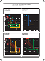
Main characteristics:
Q
available for XT4 in three-pole and four-pole versions;
Q
protections:
– against overloads (L): 0.4...1xIn adjustable protection threshold, with adjustable time trip
curve;
– against short-circuits with delay (S): 1...10xIn adjustable protection threshold, with adjustable
time trip curve;
– against instantaneous short-circuits (I): 1...10xIn adjustable protection threshold, with instantaneous trip curve;
– of the neutral in four-pole circuit-breakers;
Q
measurements:
– available from 0.2xIn in Vaux mode and starting from 0.5xIn in self supply mode; external
current or voltage transformers are not required. See table for ranges and accuracy;
– Currents: three phases (L1, L2, L3), neutral (Ne) and earth fault;
– Voltage: phase-phase, phase-neutral;
– Power: active, reactive and apparent;
– Power factor;
– Frequency and peak factor;
– Energy: active, reactive, apparent, counter;
Q
setting:
– manual setting using the relative dip-switches on the front of the trip unit, which allow the
settings to be made even when the trip unit is off;
– electronic setting, made both locally using Ekip T&P or Ekip Display accessory and via remote
control, by means of the dialogue unit Ekip Com. The electronic setting have a wider range
and a thicker regulation step.
Use of electronic setting allows other functions to be activated:
- function for protection against earth faults (G): 0.2..1xIn adjustable protection threshold,
with a time constant trip curve;
- over voltage protection 0.5…0.95 Un with a time constant trip curve;
- under voltage protection 1.05…1.2 Un with a time constant trip curve;
Q
LED:
– LED on with steady green light indicating that the trip unit is supplied correctly. The LED
comes on when the current exceeds 0.2xIn;
– red LED for each protection:
- L: LED with steady red light, indicates pre-alarm for current exceeding 0.9xI1;
- L: LED with flashing red light, indicates alarm for current exceeding setted threshold;
- fixed LED MAN/ELT show the kind of active parameters;
- LSIG: LED with steady red light, shows that the protection has tripped. After the circuitbreaker has opened, connect the Ekip TT or Ekip T&P accessory to find out which protection function tripped the trip unit;
– the trip unit is equipped with a device that detects the eventual opening solenoid disconnection thanks to the simultaneous blinking of all the LED;
Q
test connector on the front of the release:
– to connect the Ekip TT trip test unit, which allows trip test, LED test and signalling about the
latest trip happened;
– to connect the Ekip T&P unit, which allows the measurements to be read, the trip test to be
conducted, the protection functions test to be carried out, electronic setting of the protection
functions of the trip unit and of the communication parameters;
self-supply from a minimum current of 0.2xIn up; measurements starting from 0.5xIn;
the three-pole version can be accessorized with external neutral current transformer and external
neutral voltage connection kit;
with the addition of the Ekip Com in the circuit-breaker, you can:
– acquire and transmit a wide range of information via remote control;
– accomplish the circuit-breaker opening and closing commands by means of the motor
operator in the electronic version (MOE-E);
– know the state of the circuit-breaker (open/closed/trip) via remote control;
– setting the configuration and programming the unit, such as the current thresholds and the
protection function curves.
Q
Q
Q
2/11
1SDC210033D0202
Circuit-breakers for power distribution
Electronic trip units
L, S, I protection LED
LED for Electronic/Manual setting
Power-on LED
Test connector
Setting MAN/ELT
Ekip E-LSIG
Protection function
Trip curve(1)
Trip threshold
Manual setting:
I1= 0.4...1xIn step 0.04
Tolerance: trip between
1.05…1.3 I1 (IEC 60947-2)
Against overloads with
long inverse time delay trip
according to IEC 60947-2 Electronic setting:
I1= 0.4...1xIn step 0.01
Tolerance: trip between
1.05…1.3 I1 (IEC 60947-2)
Manual setting:
I2 = OFF 3-6-9
Tolerance: ±10%
Excludability
Relation
Thermal
memory
–
t = k/l2
–
–
t = k/l2
Yes
Yes
t=k
–
Yes
t = k/l2
–
Yes
t = k/l2
–
)40ms
Yes
t=k
–
)40ms
Yes
t=k
–
Yes
t = k/l2
–
Yes
t=k
–
Yes
t=k
–
Manual setting:
t1 = 12-36s
at I=3xI1
Tolerance: ±10% up to 4xIn
±20% from 4xIn
Electronic setting:
t1 = 3...60s
at I=3xI1 step 0.5
Tolerance: ±10% up to 4xIn
±20% from 4xIn
Manual setting:
t2= 0.10-0.20s
at 10xIn
Tolerance: ±15% t2>100ms
±20% t2)100ms
Against short-circuits
with inverse short (t=k/I2)
or indipendent (t=k) time
delay trip
Electronic setting:
I2 = 1...10xIn step 0.1
Tolerance: ±10%
Electronic setting:
t2 = 0.05...1s
at 10xIn step 0.01
Tolerance: ±10% up to 4xIn
±20% from 4xIn
Electronic setting:
I2 = 1...10xIn step 0.1
Electronic setting:
t2 = 0.05...0.4s step 0.01
Tolerance: ±10%
Tolerance: ±10% up to 4xIn
±20% from 4xIn
Manual setting:
I3 = OFF 1-3-4-7-9-10
Against short-circuits with
adjustable threshold and
instantaneous trip time
Tolerance: ±20%
Electronic setting:
I3 = 1...10xIn step 0.1
Tolerance: ±10%
Against earth fault with
independent time delay
trip(2)
UV
OV
(1)
Standard
adjustable constant time
Against overvoltage
with adjustable constant
time
Tollerances in case of:
– self-powered trip unit at full power;
– 2 or 3 phase power supply.
In conditions other than those considered,
the following tollerance hold:
2/12
1SDC210033D0202
Electronic setting:
I4 = 0.2...1xIn step 0.02
Electronic setting:
t4 = 0.1...0.8s step 0.05s
Tolerance: ±10%
Tolerance: ±15%
Electronic setting:
Electronic setting:
U8 = 0.5...0.95xUn step=0.01xUn t8 = 0.1...5s step 0.1s
Tolerance: ±5%
Tolerance: min (±20% ±100ms)
Electronic setting:
Electronic setting:
U9 = 1.05...1.2xUn step=0.01xUn t9 = 0.1...5s step 0.1s
Tolerance: ±5%
Tolerance: min (±20% ±100ms)
(2)
Protection
L
S
I
G
Trip threshold
release between 1.05 and 1.3 x I1
±10%
±15%
±15%
Trip time
±20%
±20%
)60ms
±20%
Protection G is inhibited for currents higher than 2 In.
Value
Current
Phase current (I1, I2, I3, IN)
Range
Accuracy
Specified measuring range
0 … 12 In
Cl 1
0.2 … 1.2 In
Phase current minimum value
Phase current maximum value
Ground current (Ig)
Voltage
Power
Active
Reactive
Apparent
Energy
Active
0 … 4 In
–
–
Phase voltage runtime,
max and min
(V1N, V2N, V3N) (1)
0 … 828 V
±0.5%
100 … 400 V
Line voltage runtime,
max and min
(U12, U23, U31)
0 … 828 V
±0.5%
100 … 690 V
Phase power runtime,
max and min
(P1, P2, P3) (1)
-207 kW … 207 kW
Cl 2
-207 kW … -1 kW
1 kW … 207 kW
Total power runtime,
max and min
-1 MW … 1 MW
Cl2
-1 MW … -3 kW
3 kW … 1 MW
Phase power runtime,
max and min
(Q1, Q2, Q3) (1)
-207 kvar … 207 kvar
Cl 2
-207 kvar … -1 kvar
1 kvar … 207 kvar
Total power runtime,
max and min
-1 Mvar … 1 Mvar
Cl 2
-1 Mvar … -3 kvar
3 kvar … 1 Mvar
Phase power runtime,
max and min
(S1, S2, S3) (1)
0 … 207 kVA
Cl 2
1 kVA … 207 kVA
Total power runtime,
max and min
0 … 1 MVA
Cl 2
3 kVA … 1 MVA
1 kWh … 2 TWh
Cl 2
1 kWh … 2 TWh
1 kvarh … 2 Tvarh
Cl 2
1 kvarh … 2 Tvarh
1 kVAh … 2 TVAh
Cl 2
1 kVAh … 2 TVAh
11th (50 - 60Hz)
–
–
0 … 1000%
±10%
0 … 500%
45 … 66 Hz
±0.5%
45 … 66 Hz
-1 … 1
±2%
-1 … -0.5
0.5 … 1
Total energy
Incoming energy
Outgoing energy
Reactive
Total energy
Incoming energy
Outgoing energy
Apparent
Power quality
Total energy
Harmonic analisys
(2)
THD of phase L1, L2, L3
(2)
Frequency runtime, max, min
PF of phase L1, L2, L3
(1)
(2)
(1)
Not available if Neutral is not connected
Available on demand by sending a Modbus command
2/13
1SDC210033D0202
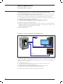
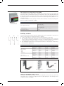
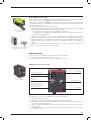
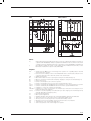
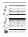
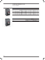
Circuit-breakers for motors protection
Main characteristics
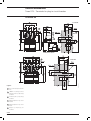
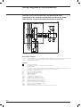
The safety and reliability of the solution are important aspects that must be considered when
choosing and manufacturing the system for starting(G4.3 and G4.4) and monitoring motors.
Start-up is a particularly critical phase for the motor itself and for the installation powering it. Even
rated service needs to be adequately monitored and protected so as to deal with any faults that
might occur.
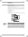
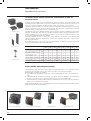
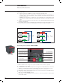
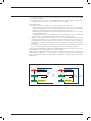
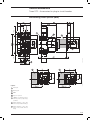
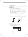
When it comes to direct starting, ABB SACE proposes two different solutions:
Q
a conventional system with three poles a circuit-breaker equipped with a magnetic only trip
unit for protection against short-circuits, a thermal relay for protection against overloads and
phase failure or imbalance, and a contactor to operate the motor;
Q
an advanced protection system which integrates all the protection and monitoring functions,
and a contactor for operating the motor, in the circuit-breaker itself.
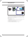
Several different factors must be considered when choosing and coordinating the protection and
operating devices, e.g.:
Q
the electrical specifications of the motor (type, power rating, efficiency, cos );
Q
the starting type and diagram;
Q
the fault current and voltage in the part of the network where the motor is installed.
Circuit-breaker with
electronic trip unit
Ekip M-LRIU
Circuit-breaker
with magnetic
only trip unit
PR212/CI
Contactor
Contactor
Thermal relay
Motor
Motor
PTC
Conventional system
Advanced protection system
Consult the QT7 Technical Application Paper: “The asynchronous three-phase motor: general information and ABB’s offer for coordinating the protections” for further details.
The motor protection and operating devices must be chosen in accordance with the coordination
tables provided by ABB either through documentation “Coordination tables” or on the web site:
http://www.abbcontrol.fr/coordination_tables/.
2/14
1SDC210033D0202
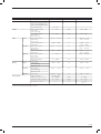
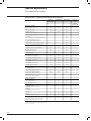
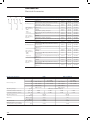
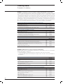
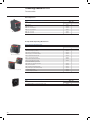
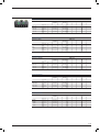
Characteristics of circuit-breakers for protecting motors
Size(G2.1)
[A]
Poles
[Nr.]
Rated service voltage, Ue(G2.4)
(AC) 50-60Hz
(DC)
Rated insulation voltage, Ui(G2.5)
Rated impulse withstand voltage, Uimp(G2.6)
Versions
Breaking capacities
Trip Units
[V]
XT2
XT3
XT4
160
250
160/250
3
3
3
690
690
690
[V]
500
500
500
[V]
1000
800
1000
[kV]
8
8
8
Fixed, Withdrawable, Plug-in
Fixed, Plug-in
Fixed, Withdrawable, Plug-in
N
S
H
L
V
N
S
N
S
H
L
Magnetic, Electronic
Magnetic
Magnetic, Electronic
MF/MA
Q
Q
Q
Ekip M-I
Q
In = 20A, 32A, 52A, 100A
Ekip M-LIU
V
In = 25A, 63A, 100A
V
In = 40A, 63A, 100A, 160A
Ekip M-LRIU
V
In = 25A, 63A, 100A
V
In = 40A, 63A, 100A, 160A
Q
Q
Interchangeability
V
Q Complete circuit-breaker
V Loose trip unit
2/15
1SDC210033D0202
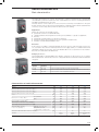
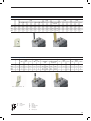
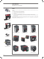
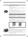
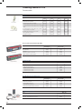
Circuit-breakers for motors protection
Magnetic trip units
MF/MA
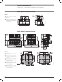
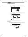
Main characteristics:
Q
available for XT2, XT3 and XT4 in the three-pole version only, these trip units are mainly used for
protecting motors, in conjunction with a thermal relay and a contactor;
Q
protections:
– against instantaneous short-circuit (I) for XT2: for In)12.5A the protection threshold I is fixed
at 14xIn, whereas for In>12.5A the protection threshold I is adjustable from 6..14xIn;
– against instantaneous short-circuit (I) for XT3: the protection threshold I is adjustable from
6..12xIn;
– against instantaneous short-circuit (I) for XT4: the protection threshold I is adjustable from
5..10xIn;
Q
the magnetic protection setting is made by turning the relative cursor on the front of the release.
Rotary switch for magnetic
protection setting
XT2
MF/MA
In [A]
1(1)
2(1)
4(1)
8.5(1)
12.5(1)
I3 = MF
14
28
56
120
175
I3 = 14xIn [A]
I3 = 6..14xIn [A] I3 = MA
(1)
20
32
52
120...280
192…448
314…728
80
100
480…1120 600...1400
Available only as complete circuit-breaker
XT3
MA
In [A]
100
125
I3 [A]
600…1200
750…1500
160
200
960…1920 1200…2400
I3 = 6..12xIn
XT4
MA
In [A]
I3 [A]
10(1)
I3 = 5..10xIn
(1)
Available only as complete circuit-breaker
2/16
1SDC210033D0202
12.5(1)
20
32
52
80
100
125
160
200
50…100 62.5…125 100…200 160…320 260…520 400…800 500…1000 625…1250 800…1600 1000…2000
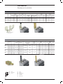
Circuit-breakers for motors protection
Electronic trip units
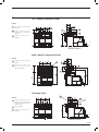
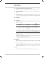
Ekip M-I
Main characteristics:
Q
Q
Q
Q
Q
only available for XT2 in three-pole version. It is normally used in combination with a thermal relay
and a contactor for motor protection;
protections:
– against instantaneous short-circuit (I): protection threshold adjustable from 6...14xIn, with
instantaneous trip curve;
manual setting by means of the special dip-switches positioned on the front of the trip unit,
which allow its adjustment even with the trip unit off;
LED:
– fixed green LED which indicates correct operation of the trip unit; the LED lights up for a current over 0.2xIn;
Test connector positioned on the front of the trip unit:
– for connection of the Ekip TT test unit, which allows the trip test and the LED test;
– for connection of the Ekip T&P unit, which allows the measurements to be read, to carry out
the trip test and to carry out the protection function test;
– self-supply starting from a minimum current of 0.2 x In.
LED power-on
Slot for lead seal
Test Connector
Dip Switch for setting
protection function I
Ekip M-I
Protection function
Trip threshold
Against short-circuits with
adjustable threshold and
instantaneous trip time
Manual setting:
I 3 = 6-6,5-7-7,5-8-8,5-9-9,5-1010,5-11-11,5-12,5-13-13,514xIn
Trip curve (1)
)15ms
Excludability Relation
–
t=k
Thermal
memory
–
Tolerance: ±10%
(1)
Tollerances in case of:
– self-powered trip unit at full power;
– 2 or 3 phase power supply.
In conditions other than those considered, the
following tollerance hold:
Protection
I
Trip threshold
±15%
Trip time
)60ms
2/17
1SDC210033D0202
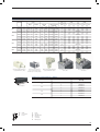
Circuit-breakers for motors protection
Electronic trip units
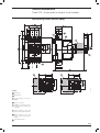
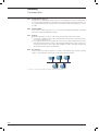
Ekip M-LIU
Main characteristics:
Q available for XT2 and XT4 in the three-pole version, this device protects motors. The L protection
function protects the motor against overloads, in accordance with the indications and classes
defined by standard IEC 60947-4-1;
Q protections:
– against overloads (L): 0.4...1xIn adjustable threshold. The operating time is established by
choosing the operating class defined by Standard IEC 60947-4-1: Class 3E, 5E, 10E, 20E;
– against short-circuits (I): 6...13xIn adjustable threshold with instantaneous operating time;
– against phase loss (U): the protection can be selected either in the ON or OFF position. When
the selector is in the ON position, the threshold is 50% I1, with fixed operating time;
Q manual setting using the relative dip-switches on the front of the release;
Q LED:
– LED on with steady green light indicating that the trip unit is supplied correctly. The LED
comes on when the current exceeds 0.2xIn;
– red LED for each protection:
- L: LED with steady red light, indicates pre-alarm for current exceeding 0.9xI1;
- L: LED with flashing red light, indicates alarm for current exceeding setted threshold;
- LIU: LED with steady red light, shows that the protection has tripped. After the circuitbreaker has opened, connect the Ekip TT or Ekip T&P accessory to find out which protection function tripped the trip unit;
– release Ekip M-LIU is equipped with a trip coil disconnection detection device that detects
whether the opening solenoid has disconnected. Signalling is made by all the red LEDs
flashing simultaneously;
Q test connector on the front of the release:
– to connect the Ekip TT trip test unit, which allows trip test, LED test and signalling about the
latest trip happened;
– to connect the Ekip T&P unit, which allows the measurements to be read, the trip test to be
conducted and the protection function test to be carried out;
Q thermal memory always active;
Q self-supply starting from a minimum current of 0.2xIn.
Power-on LED
L, I, U protection LED
Slot for lead seal
Test connector
Dip switch for L protection
function setting
Dip switch for I protection
function setting
Dip switch for the trip classes setting
according to IEC 60947-4-1
U protection function ON-OFF
Ekip M-LIU
Protection function
Manual setting:
Against overloads with long I 1= 0.4...1xIn step 0.04
inverse time delay according Tolerance:
to IEC 60947-4-1 Standard trip between 1.05…1.2xI
1
Against short-circuits with
adjustable threshold and
instantaneous trip time
Aganist phase loss with
indipendend time delay
(IEC 60947-4-1)
(1)
Tollerances in case of:
– self-powered trip unit at full power;
– 2 or 3 phase power supply.
In conditions other than those considered,
the following tollerance hold:
2/18
1SDC210033D0202
Trip curve(1)
Trip threshold
Manual setting:
Operating class:
3E, 5E, 10E, 20E
Excludability Relation
Thermal
memory
–
t = k/l 2
Yes
–
t=k
–
Yes
t=k
–
Tolerance: ±10% up to 4xIn
±20% from 4xIn
Manual setting:
I 3 = 6...13xIn step 1
)20ms
Tolerance: ±10%
Manual setting:
I 6 = ON / OFF
When ON, I 6=50% I1
Manual setting:
When ON, t 6= 2s
Tolerance: ±10%
Tolerance: ±15%
Protection
L
I
U
Trip threshold
release between 1.05 and 1.2 x I1
±15%
±20%
Trip time
±20%
)60ms
±20%
Ekip M-LRIU
Main characteristics:
Q
available for XT2 and XT4 in the three-pole version, this device is generally used for protecting
integrated motors;
Q
protections:
– against overloads (L): 0.4...1xIn adjustable threshold. The operating time is established by
choosing the operating class defined by standard IEC 60947-4-1;
– rotor locking (R): with adjustable threshold in the OFF position or from 3...9xI1, with settable
operating time;
– against instantaneous short-circuits (I): with adjustable threshold from 6...13xIn and instantaneous operating time;
– against phase loss (U): with adjustable threshold in the ON or OFF positions;
Q
setting:
– manual setting using the relative dip-switches on the front of the trip unit, which allow the
settings to be made even when the trip unit is off;
– electronic setting, made both locally using Ekip T&P or Ekip Display accessory and via remote
control, by means of the dialogue unit Ekip Com. Use of electronic setting allows other functions to be activated:
- function for protection against earth faults (G): 0.2..1xIn adjustable protection threshold,
with a time constant trip curve;
- duty mode setting (Normal/Heavy):
- the Normal duty mode requires use of a circuit-breaker and a contactor. In the case of
tripping, the Ekip M-LRIU release commands the opening of the contactor via PR212/CI;
- the Heavy duty mode foresees circuit-breaker opening for all overcurrent conditions, and
just the function of motor operation is entrusted to the contactor;
- BACK UP function:
- this protection is designed to handle the situation whereby, in the Normal duty mode, the
opening command transmitted to the contactor via PR212/CI has not been implemented, i.e. the contactor has not tripped. If this happens, the Ekip M-LRIU release transmits
a trip command directly to the circuit-breaker after having waited a time defined. A waiting time between the command transmitted to the contactor and the back-up command
transmitted to the circuit-breaker is required so as to take the contactor opening time
into account;
- PTC protection setting:
- PTC: this protection, monitors the temperature inside the protected motor by means
of a PTC sensor. If the temperature is too high, the Ekip M-LRIU release will command
contactor opening (if the mode is “Normal”) or circuit-breaker opening (if the mode is
“Heavy”). To realize this protection is necessary to order the connector available for PTC;
Q
LED:
– LED on with steady green light indicating that the trip unit is supplied correctly. The LED
comes on when the current exceeds 0.2xIn;
– red LED for each protection:
- L: LED with steady red light, indicates pre-alarm for current exceeding 0.9xI1;
- L: LED with flashing red light, indicates alarm for current exceeding setted threshold;
- fixed LED ELT show the kind of active parameters;
- LRIU: LED with steady red light, shows that the protection has tripped. After the circuitbreaker has opened, connect the Ekip TT or Ekip T&P accessory to find out which protection function tripped the trip unit;
– Ekip M-LRIU is equipped with a trip coil disconnection detection device that detects whether
the opening solenoid has disconnected. Signalling is made by all the LEDs flashing simultaneously;
test connector on the front of the release:
– to connect the Ekip TT trip test unit, which allows trip test, LED test and signalling about the
latest trip happened;
– to connect the Ekip T&P unit, which allows the measurements to be read, the trip test to be
conducted, the protection function test to be carried out, and electronic setting of the protection function of the release and of the communication parameters;
Q
Q
thermal memory always active;
Q
self-supply from a minimum current of 0.2xIn up;
2/19
1SDC210033D0202
Circuit-breakers for motors protection
Electronic trip units
Q
with the addition of the Ekip Com in the circuit-breaker, you can:
– acquire and transmit a wide range of information via remote control;
– accomplish the circuit-breaker opening and closing commands by means of the motor
operator in the electronic version (MOE-E);
– know the state of the circuit-breaker (open/closed/trip) via remote control;
– setting the configuration and programming parameters of the unit, such as the current thresholds and the protection function curves.
LED for Electronic/Manual setting
L, R, I, U protection LED
Setting MAN/ELT
Dip switch for the trip
classes setting according
to IEC 60947-4-1
Slot for lead seal
Power-on LED
Test connector
Dip switch for L protection
function setting
Dip switch for I protection
function setting
R protection function ON-OFF
U protection function ON-OFF
Dip switch for R protection function setting
Dip switch for the trip curve selection
Ekip M-LRIU
Protection function
Manual setting:
I1 = 0.4...1xIn step 0.04
R
Trip curve (1)
Trip threshold
Excludability Relation Thermal
memory
Manual setting:
Trip class: 3E, 5E, 10E, 20E
–
t = k/l2
Yes
–
t = k/l2
Yes
Yes
t=k
–
Yes
t=k
–
)40ms
–
t=k
–
)40ms
–
t=k
–
Yes
t=k
–
Tolerance: ±20%
Yes
t=k
–
Electronic setting:
I4 = 0.2...1xIn step 0.1In
Electronic setting:
t4 = 0.1...0.8s step 0.01
Yes
t=k
–
Tolerance: ±10%
Tolerance: ±15%
Tolerance: ±10% up to 4xIn
±20% from 4xIn
Tolerance:
Against overloads with
trip between 1.05...1.2xI1
long inverse time delay trip
Electronic
setting:
according to IEC 60947-4-1
I1 = 0.4...1xIn step 0.01
Electronic setting:
Trip class: 3E, 5E, 10E, 20E
Tolerance:
trip between 1.05...1.2xI1
Tolerance: ±10% up to 4xIn
±20% from 4xIn
Against rotor block with
delayed trip and with an
indipendent time delay trip
(IEC 60947-4-1)
Against short-circuits
threshold with adjustable
threshold and istantaneous
trip time
Manual setting:
I5 = OFF, 3, 6, 9xI1
Manual setting: t5 = 1, 4s
Tolerance: ±10%
Tolerance: ±10% up to 4xIn
±20% from 4xIn
Electronic setting:
I5 = OFF, 3...9xI1 step 0.1I1
Electronic setting:
t5 =1...4s step 0.5
Tolerance: ±10%
Tolerance: ±10% up to 4xIn
±20% from 4xIn
Manual setting:
I3 = 6-8-11-13xIn
Tolerance: ±10%
Electronic setting:
I3 = 1...13xIn
Tolerance: ±10%
Manual setting:
I6 = On / Off
When ON, I6 = 50% I1
Aganist phase current
Tolerance: ±15%
unbalanced or loss of phase
with tripping at indipendent Electronic setting:
I6 = On / Off
time (IEC 60947-4-1)
When ON, I6 = 10%..50% I1 step
10% I1
Manual setting:
t6 = 2s
Tolerance: ±20%
Electronic setting:
t6 = 0...5s step 0.5
Tolerance: ±15%
Against earth fault with
indipendent time delay trip(2)
(1)
Tollerances in case of:
– self-powered trip unit at full power;
– 2 or 3 phase power supply.
In conditions other than those
considered, the following tollerance hold:
2/20
1SDC210033D0202
Protection
L
R
I
U
G
Trip threshold
release between 1.05 and 1.2 x I1
±20%
±20%
±20%
±15%
Trip time
±20%
±20%
)60ms
±20%
±20%
(2)
Protection G is inhibited for currents higher than
2 In.
Circuit-breakers for generator protection
Main characteristics
SACE Tmax XT circuit-breakers can be equipped with thermomagnetic trip units with a low magnetic threshold.
This type of release can been designed and made so as to provide a solution for protecting small
generators and distribution networks with very long cables (slight end of line fault current owing to
the high cable impedance).
Generator protection requires a low magnetic threshold, typically about three times circuit-breaker’s
rated current, so as to “cut” the short-circuit current in the “transient” zone of the decrement curve
of the generator fault current. Consult the “Electrical installation handbook” ABB SACE guide vol. 2
for further details.
t [s]
10
synchronous
phase
1
transient
phase
10-1
10-2
1SDC21092EF0001
sub transient
phase
10-3
10 2
x I1
10
1
Characteristics of circuit-breakers for protecting generators
Size (G2.1)
Poles
Rated service voltage, Ue (G2.4)
Trip units
TMG
Ekip G-LS/I
Interchangeability
XT4
250
160/250
[Nr.]
3, 4
3, 4
3, 4
[V]
690
690
690
(DC)
[V]
500
500
500
[V]
1000
800
1000
[kV]
8
8
8
Rated impulse withstand voltage, Uimp(G2.6)
Versions
XT3
160
(AC) 50-60Hz
Rated insulation voltage, Ui (G2.5)
Breaking capacities
XT2
[A]
Fixed, Withdrawable, Plug-in
N
S
Fixed, Plug-in
N
S
Thermomagnetic, Electronic
Thermomagnetic
Q
Q
Fixed, Withdrawable, Plug-in
N
S
Electronic
V
In = 10A, 25A, 63A, 100A, 160A
V
In = 40A, 63A, 100A, 160A, 250A
Q
Q
Q Complete circuit-breaker
V Loose trip unit
2/21
1SDC210033D0202
Circuit-breakers for generator protection
Main characteristics
TMG
Main characteristics:
Q
available for XT2 and XT3 in the three-pole and four-pole versions;
Q
protections:
– against overloads (L): adjustable 0.7...1xIn protection threshold, with inverse long-time trip
curve;
– against instantaneous short-circuits (I): fixed 3xIn protection threshold, with instantaneous
trip curve;
– 100% neutral protection in four-pole circuit-breakers;
Q
the thermal protection setting is made by turning the relative cursor on the front of the release.
Example with XT3 250A
Rotary switch for thermal
protection setting
XT2
TMG
In [A]
16 (1)
20(1)
25 (1)
32(1)
40 (1)
50(1)
63(1)
80
100
125
160
Neutral [A] - 100%
16
20
25
32
40
50
63
80
100
125
160
I1 = 0.7…1xIn
I 3 [A]
160
160
160
160
200
200
200
240
300
375
480
Neutral [A] - 100%
160
160
160
160
200
200
200
240
300
375
480
I 3 = 3xIn
(1)
Available only as complete circuit-breaker
XT3
TMG
In [A]
63
80
100
125
160
200
250
Neutral [A] - 100%
63
80
100
125
160
200
250
I1 = 0.7…1xIn
I 3 = 3xIn
2/22
1SDC210033D0202
I 3 [A]
400
400
400
400
480
600
750
Neutral [A] - 100%
400
400
400
400
480
600
750
Ekip G-LS/I
Main characteristics:
Q
available for XT2 and XT4 in the three-pole and four-pole versions. Allows the protection against
overloads to be extensively adjusted;
Q
protections:
– against overloads (L): I1=0.4...1xIn adjustable protection threshold, with inverse long-time trip
curve;
– against delayed short-circuits (S): 1...10xIn adjustable protection threshold, with adjustable
trip curve (as an alternative to I protection);
– against instantaneous short-circuits (I): 1...10xIn adjustable protection threshold, with instantaneous operating time (as an alternative to S protection);
– neutral, in four-pole circuit-breakers, can be set in the OFF, ON positions at 50% or 100% of
the phases;
Q
manual setting using the relative dip-switches on the front of the trip unit, which allow the settings
to be made even when the trip unit is off;
Q
LED:
– LED on with steady green light indicating that the trip unit is supplied correctly. The LED
comes on when the current exceeds 0.2xIn;
– red LED for each protection:
- L: LED with steady red light, indicates pre-alarm for current exceeding setted threshold;
- L: LED with flashing red light, indicates alarm for current exceeding setted threshold;
- LS/I: LED with steady red light, shows that the protection has tripped. After the circuitbreaker has opened, connect the Ekip TT or Ekip T&P accessory to find out which protection function tripped the trip unit;
– Ekip G-LS/I is equipped with a trip coil disconnection detection device that detects whether
the opening solenoid has disconnected. Signalling is made by all the LEDs flashing simultaneously;
Q
test connector on the front of the release:
– to connect the Ekip TT trip test unit, which allows trip test, LED test and signalling about the
latest trip happened;
– for connecting the Ekip T&P unit which allows the measurements to be read and the trip test
to be carried out;
Q
thermal memory which can be activated by Ekip T&P;
Q
self-supply from 0.2xIn up.
2/23
1SDC210033D0202
Circuit-breakers for generator protection
Main characteristics
Dip switch for the selection between S protection
function or I protection function
L, S, I protection LED
Power-on LED
Test connector
Slot for lead seal
Dip switch for LS/I protection function setting
Dip switch for the trip curve selection
Ekip G-LS/I
Protection function
Against overloads with
inverse long-time delayed
tripping according to
IEC 60947-2 standard
Against short-circuit with
indipendent time delay trip
Against short-circuits with
adjustable threshold and
istantaneous trip time
(1)
Trip threshold
Manual setting:
I 1 = 0.4...1xIn step 0.04
Manual setting:
t1 = 3-6s at I = 3xI1
Tolerance:
trip between 1.05…1.3xI 1
(IEC 60947-2)
Tolerance: ±10% up to 4xIn
±15% from 4xIn
Manual setting:
t 2 = 0.05-0.075-0.1-0.2s
I 2 = 1-1.5-2-2.5-3-3.5-4.5-5.5- Tolerance: ±10% t >0.075
2
6.5-7-7.5-8-8.5-9-10xIn
±20% t )0.075
2
2/24
1SDC210033D0202
Excludability
Relation
Thermal
memory
–
t = k/l 2
Yes
Yes
t=k
–
Yes
t=k
–
Tolerance: ±10% up to 2xIn
±20% from 2xIn
Manual setting:
I 3 = 1-1.5-2-2.5-3-3.5-4.5-5.56.5-7-7.5-8-8.5-9-10xIn
Tolerance: ±10%
Tollerances in case of:
– self-powered trip unit at full power;
– 2 or 3 phase power supply.
In conditions other than those considered, the following tollerance hold:
Protection
L
S
I
Trip curve(1)
Trip threshold
release between 1.05 and 1.3 x I1
±10%
±15%
Trip time
±20%
±20%
)60ms
)20ms
Circuit-breakers for oversized neutral protection
Main characteristics
The SACE Tmax XT range of circuit-breakers with oversized neutral is used in certain applications
where harmonics or unbalance loads or single phase create an overload on the neutral conductor.
Under these conditions, a current of a considerable value could travel along the neutral conductor.
In particular, third-order harmonics and relative multiples add together on the neutral and give rise to
a current value that could be higher than the one which travels along the phase conductors.
For this reason, circuit-breakers with oversized neutral provide adequate protection in installations
where the neutral conductor is sized with a larger section than the phase conductors.
The main types of equipment that generate harmonics are given below by way of example:
Q personal computers;
Q fluorescent lamps;
Q static converters;
Q no-break power units;
Q variable speed drives;
Q welding machines.
By and large, the wave shape is distorted owing to the presence of semiconductor devices able to
conduct for a fraction of the entire cycle, creating discontinuous trends and consequently introducing numerous harmonics.
Consult the “Electrical installation handbook” ABB SACE guide vol. 2 for further details.
Characteristics of circuit-breakers for oversized neutral protection
Size(G2.1)
Uninterrupted nominal current, In
Poles
XT2
XT4
[A]
160
160/250
[A]
10, 63, 100
40, 63, 100, 160
[Nr.]
Rated service voltage, Ue(G2.4)
(AC) 50-60Hz
Rated insulation voltage, Ui(G2.5)
Rated impulse withstand voltage, Uimp
(G2.6)
4
4
[V]
690
690
[V]
1000
1000
[kV]
Versions
Breaking capacity
Trip units
N
8
8
Fixed, Withdrawable, Plug-in
Fixed, Withdrawable, Plug-in
S
H
L
V
N
S
H
Electronic
Electronic
Ekip N-LS/I
V
V
Interchangeability
Q
Q
L
V
Q Complete circuit-breaker
V Loose trip unit
2/25
1SDC210033D0202
Circuit-breakers for oversized neutral protection
Main characteristics
Ekip N-LS/I
Main characteristics:
Q available for XT2 and XT4 in the four-pole version;
Q protections:
– against overload (L): I1=0.4...1xIn adjustable protection threshold, with inverse long-time trip
curve;
– against delayed short-circuits (S): 1...10xIn adjustable protection threshold, with adjustable
trip curve (as an alternative to I protection);
– against instantaneous short-circuit (I): 1...10xIn adjustable protection threshold, with instantaneous operating time (as an alternative to S protection);
– neutral can be set in the OFF or ON positions, at 100% or at 160% of the phases;
Q manual setting using the relative dip-switches on the front of the trip unit, which allow the settings to be made even when the trip unit is off;
Q LED:
– LED on with steady green light indicating that the trip unit is supplied correctly. The LED
comes on when the current exceeds 0.32xIn;
– red LED for each protection:
- L: LED with steady red light, indicates pre-alarm for current exceeding 0.9xI1;
- L: LED with flashing red light, indicates alarm for current exceeding setted threshold;
- LS/I: LED with steady red light, shows that the protection has tripped. After the circuitbreaker has opened, connect the Ekip TT or Ekip T&P accessory to find out which protection function tripped the trip unit;
– Ekip N-LS/I is equipped with a device that detects whether the opening solenoid has disconnected. Signalling is made by all the LEDs flashing simultaneously;
Q test connector on the front of the release:
– to connect the Ekip TT trip test unit which allows trip test, LED test and signalling about the
latest trip happened;
– for connecting the Ekip T&P unit, which allows the measurements to be read and the trip test
to be carried out;
Q thermal memory which can be activated by Ekip T&P;
Q self-supply from 0.32xIn.
Dip switch for the selection between S
protection function or I protection function
L, S, I protection LED
Power-on LED
Dip switch for
neutral selection
Test connector
Slot for lead seal
Dip switch for LS/I protection function setting
Dip switch for the trip curve selection
Ekip N-LS/I
Protection function
Against overloads with inverse
long-time delayed tripping.
According to IEC 60947-2
Standard
Against short-circuits with
inverse short indipendent time
delay trip (t=k)
Against short-circuits with
istantaneous trip time
Time-current curve(1)
Trip threshold
Manual setting:
I1 = 0.4...1xIn step 0.04
Manual setting:
t1 = 12-36s at I= 3xI1
Tolerance: trip between
1.05…1.3xI1 (IEC 60947-2)
Tolerance: ±10% up to 4xIn
±15% from 4xIn
t2 = 0.1-0.2s
Manual setting:
I2 = 1-1.5-2-2.5-3-3.5-4.5-5.5- Tolerance: ±15%
6.5-7-7.5-8-8.5-9-10xIn
Excludability Relation
–
t = k/l2
Yes
Yes
t=k
–
Yes
t=k
–
Tolerance: ±10%
Manual setting:
I3 = 1-1.5-2-2.5-3-3.5-4.5-5.56.5-7-7.5-8-8.5-9-10xIn
)20ms
Tolerance: ±10%
(1)
Tollerances in case of:
– self-powered trip unit at full power;
– 2 or 3 phase power supply.
In conditions other than those considered, the following tollerance hold:
2/26
1SDC210033D0202
Thermal
memory
Protection
L
S
I
Trip threshold
release between 1.05 and 1.3 x I1
±10%
±15%
Trip time
±20%
±20%
)60ms
Switch-disconnectors
Main characteristics
The switch-disconnector (or, in short, disconnector) is a device created from the corresponding
circuit-breakers (of which it features the same overall dimensions, versions, fastening mechanisms
and ability to be fitted with accessories).
The main function of these devices is to disconnect the circuit they are installed in. In the open
position, the disconnector disconnects and guarantees a sufficient insulation distance (between the
contacts) to assure safety and to prevent an electrical arc from striking.
XT1D
Applications
Switch-disconnectors are generally used as:
Q general disconnectors of subswitchboards;
Q operating and disconnecting devices for lines, pan-assembliess or groups of equipment;
Q bus-ties;
Q general disconnecting devices for groups of machines;
Q general group disconnecting devices for motor operation and protection;
Q insulation of small tertiary distribution units.
Protection
A disconnector is unable to automatically break the short-circuit or overload current. For this reason, each switch-disconnector must be protected on the supply side by a coordinated device that
safeguards it against short-circuits. The circuit-breaker able to act as a protection for each switchdisconnector is indicated in the table below.
XT3D
Category of use (G2.11)
The CEI EN 60947-3 Standard defines the utilisation categories for disconnectors in accordance
with the table below. Tmax XT disconnectors comply with the AC21A, AC22A and AC23A utilisation
categories.
Class of use
Infrequent
operation
Frequent
operation
Typical applications
AC-21A
AC-21B
Control of resistive loads with overloads of modest entity
AC-22A
AC-22B
Control of mixed resistive and inductive loads with overloads of modest entity
AC-23A
AC-23B
Control of motors or other highly inductive loads
XT4D
Characteristics of switch-disconnectors
Size
(G2.1)
XT1D
XT3D
XT4D
[A]
160
250
250
Rated operating current in class AC21, Ie(G.2.12)
[A]
160
250
250
Rated operating current in class AC22, Ie(G.2.12)
[A]
160
250
250
Rated operating current in class AC23, Ie(G.2.12)
[A]
125
200
200
[Nr.]
3, 4
3, 4
3, 4
[V]
690
690
690
Poles
Rated service voltage, Ue(G2.4)
(AC) 50-60Hz
(DC)
Rated insulation voltage, Ui(G2.5)
Rated impulse withstand voltage, Uimp(G2.6)
Test voltage at industrial frequency for 1 min
Rated breaking capacity
in short-circuit, Icm(G2.10)
500
500
500
800
800
800
[kV]
8
8
8
[V]
3000
3000
3000
(Min) Disconnector only
[kA]
2.8
5.3
5.3
(Max) With automatic
circuit-breaker on supply side
[kA]
187
105
105
Rated short-time withstand current for 1s, Icw(G2.9)
Versions
[V]
[V]
[kA]
2
3.6
3.6
Fixed,
Plug-in
Fixed,
Plug-in
Fixed, Withdrawable,
Plug-in
2/27
1SDC210033D0202
Switch-disconnectors
Main characteristics
Switch-disconnectors coordination
Supply S.
XT1
XT2
XT3
XT4
2/28
1SDC210033D0202
Version
Icu
Load S.
XT1D
XT3D
Icw [kA]
2
3,6
XT4D
3.6
Iu Ith
160
250
250
B
18
18
18
18
C
25
25
25
25
N
36
S
50
160
36
36
36
50
50
50
H
70
70
70
70
N
36
36
36
36
S
50
H
70
160
50
50
50
70
70
70
L
120
120
120
120
V
200
150
150
150
N
36
S
50
250
36
36
50
50
N
36
36
36
S
50
50
50
H
70
70
70
L
120
120
120
V
150
150
150
160
250
Special applications
400Hz installations
The circuit-breakers used for power distribution can operate in alternating current at different frequencies from 50/60Hz (frequencies which the rated performance of the apparatus refers to) so
long as the appropriate derating coefficients are applied.
At 400Hz, the performance of the circuit-breakers is reclassified so as to take the following phenomena into account:
Q
an increase in the skin effect and increased inductive reactance in a way that is directly proportional to the frequency, overheat the conductors or the copper components that normally carry
the current in the circuit-breaker;
Q
lengthening of the hysteresis loop and reduction of the magnetic saturation value, which consequently varies the forces associated with the magnetic field to a given current value.
By and large, these phenomena influence the behaviour of both the thermomagnetic trip units and
the current interrupting parts of the circuit-breaker.
Consult the “Electrical installation handbook” ABB SACE guide for further details.
All the circuit-breakers in the SACE Tmax XT family equipped with thermomagnetic or electronic
trip units (except for the Ekip M-I, Ekip M-LIU and Ekip M-LRIU trip units) can be used in 400Hz
installations. The 10A and 25A settings for operation at 400Hz are only available on request.
Contact ABB SACE for more details about performance derating.
2/29
1SDC210033D0202
Special applications
Communication system
The XT2 and XT4 moulded-case circuit-breakers, equipped with Ekip LSI, Ekip LSIG
or Ekip M-LRIU trip unit and Ekip Com dialogue module, can be integrated in supervision systems
for control and management of electrical and technological plants.
With XT2 and XT4, equipped with thermomagnetic trip units, Ekip Com dialogue module and Electronic Motor, it is possible to read the state of the circuit-breaker remotely and to operate it.
Protocols available, for communication on bus(G5.4) network with circuit-breakers XT2 and XT4, are:
Q Modbus RTU (standard protocol of ABB SACE);
Q ProfiBus-DP (usable with ABB SACE devices, jointly with EP010 accessory);
Q DeviceNet (usable with ABB SACE devices, jointly with EP010 accessory).
Necessaries accessories for communications are:
Q Ekip Com communication module and electronic auxiliary contacts (1Q + 1SY) included in the
Ekip Com module. For further details about the Ekip Com communication module, see the
paragraph dedicated to this in the Accessories chapter;
Q Electronic motor operator MOE-E;
Q EP010- Field Bus Plug.
Configuration 1: Supervision (Electronic trip unit and Ekip Com)
+
24 V –
Modbus
Internal Bus
HMI030
Positioned in the right-hand slot of the circuit-breaker, the Ekip Com accessory connects to the Ekip
LSI, Ekip LSIG, Ekip E-LSIG or Ekip M-LRIU trip unit via connector supplied. Six cables come out
of Ekip Com, of which two are required for auxiliary supply, two for connection to the Modbus and
two for connection to Internal Bus.
This configuration allows you to:
read the measurements and settings from the electronic trip unit in remote mode;
Q program the electronic trip unit in remote mode;
Q know the state of the circuit-breaker (Open/Closed/Tripped) in remote mode;
Q visualize locally on HMI 030 all the relevant information of the CB.
Q
Consult the Electric Diagrams chapter for further details about wiring.
2/30
1SDC210033D0202
Configuration 2: Supervision and Remote control (Thermomagnetic trip unit or switchdisconnector, Ekip Com and MOE-E)
+
24 V –
+
Modbus
The Ekip Com accessory, positioned in the right-hand slot of the circuit-breaker, is connected with
the MOE-E by means of the connector on the rear of the MOE-E.
Six cables come out of the Ekip Com, of which two are needed for the auxiliary power supply and
two for connection to the Modbus.
With this configuration it is possible to:
Q read the Open/Closed/Tripped state of the circuit-breaker remotely;
Q open/close the circuit-breaker or of the switch-disconnector remotely.
For further details regarding cabling of the various devices, please refer to the chapter on Electric
Diagrams.
Configuration 3: Supervision and Remote Control (Electronic trip unit, Ekip Com and MOE-E)
+
24 V –
+
Modbus
Internal Bus
HMI030
Positioned in the right-hand slot of the circuit-breaker, the Ekip Com accessory connects to the Ekip
LSI, Ekip LSIG, Ekip E-LSIG or Ekip M-LRIU trip unit via connector supplied with Ekip Com and to
the MOE-E via connector be present on MOE-E behind. Six cables come out of Ekip Com of which
two are required for auxiliary supply, two for connection to the Modbus and two for connection to
Internal Bus.
This configuration allows you to:
Q read the measurements and settings from the solid-state release in remote mode;
Q program the electronic trip unit in remote mode;
Q read the state of the circuit-breaker (Open/Closed/Tripped) in remote mode;
Q open/close the circuit-breaker in remote mode;
Q visualize locally on HMI 030 all the relevant information of the CB.
Consult the Electric Diagrams chapter for further details about wiring.
2/31
1SDC210033D0202
Special applications
Communication system
Configuration 4: EP010 - Fieldbus Plug (Electronic trip unit, Ekip Com and EP010)
+
24 V –
+
Modbus
Modbus
Connector is to be provided by the Customer
(PDP22 for Profibus, DNP21 for Devicenet)
EP010
Internal Bus
HMI030
Positioned in the right-hand slot of the circuit-breaker, the Ekip Com accessory connects to the Ekip
LSI, Ekip LSIG, Ekip E-LSIG or Ekip M-LRIU trip unit via connector supplied and to the MOE-E via
connector be present on MOE-E behind (MOE-E connection is optional for this configuration). Six
cables come out of Ekip Com, of which two are required for auxiliary supply, two for connection to
the EP010 and two for connection to Internal Bus.
Connection of the EP010 to the network is to be made by the Customer and depends on the Fieldbus plug connector used.
With this configuration, it is possible to:
Q make the SACE Tmax XT circuit-breakers communicate in a network with Profibus or Devicenet
comunication protocol;
Q read the measurements and settings from the solid-state release in remote mode;
Q program the electronic trip unit in remote mode;
Q read the state of the circuit-breaker (Open/Closed/Tripped) in remote mode;
Q open/close the circuit-breaker in remote mode;
Q visualize locally on HMI 030 all the relevant information of the CB.
2/32
1SDC210033D0202
Configuration 5: Interface from front panel (Electronic trip unit and HMI030 Unit)
+
24 V –
HMI030
Internal Bus
With XT2 and XT4 circuit-breakers, equipped with electronical trip unit Ekip LSI, Ekip LSIG, Ekip
E-LSIG or Ekip M-LRIU, in addiction with the interface unit HMI030, it’s possible to visualize directly
on the panel door the mainly electrical magnitude values and the last trip information.
The necessary accessories, useful to permit the lecture directly from the front of the switchboard are:
Q interface device HMI030;
Q kit of 24V DC auxiliary voltage for electronic trip unit.
Four cables come out of the Ekip E-LSIG, Ekip LSI, Ekip LSIG or Ekip M-LRIU trip unit, two of which
are needed for the auxiliary power supply and two for connection to the HMI030 on Internal Bus.
This configuration makes it possible to read the measurements and alarms from the electronic trip
unit by means of the HMI030 accessory positioned on the front of the panel.
For further details on cabling the various different devices, refer to the Electric Diagram Chapter.
2/33
1SDC210033D0202
Special applications
Communication system
Measurement, signalling and available data functions
Ekip LSI
Ekip M-LRIU
Ekip E-LSIG
Ekip LSIG
Ekip LS/I
TM
Switchdisconnector
Electrical quantities
Q
Phase current (IL1, IL2, I L3)
Neutral current (IN)
Q
Q
(1)
Q
Ground current (Ig)
Q
(1)
Q
Q
Q
Phase to phase voltage (V12-V23-V31)
Phase-Neutral Voltage (V1N-V 2N-V 3N)
Q
Q
(2)
Frequency
Q
Power (active P, reactive Q, apparent S)
total power and phase power (2)
Q
Power factor (total and phase)
Q
(2)
Energy (active, reative, apparent) total
Q
Harmonic calcualtion (THDi, spectre)
Q
Status information
CB status (open, closed, tripped)
Q
Modality (local, remote)
Q
Q
Q
Protection parameters
Q
Q
Q
Thermal memory
Q
Q
Q
Total number of operation
Q
Q
Q
Total number of protection trips
Q
Q
Q
Total number of trip test
Q
Q
Q
Total number of manual operations
Q
Q
Q
Total number of failed trip
Q
Q
Q
Last trip data recording
20
20
20
I Protection (trip)
Q
Q
Q
S Protection (timing and trip)
Q
L Protection (timing and trip)
Q
Q
Q
G Protection (timing and trip)
Q (1)
Q
Q
Q
Q
Maintenance data
Protection alarm
Q
Q
R Protection
U Protection (timing and trip)
Q
Q
Q
Trip command failed
Q
Q
Q
Trip coil disconnected
Q
Q
Q
CB Open/CB Close
(with MOE-E motor operator)
Q
Q
Q
Q
CB Reset
(with MOE-E motor operator)
Q
Q
Q
Q
Alarm Reset
Q
Q
Q
Trip test
Q
Q
Q
Protection parameter setting
Q
Q
Q
Q
Q
Q
L protection Prealarm
(3)
Diagnostic Alarm
Commands
Run Time Events
CB status changes, protection status
change and alarms status change
(1)
(2)
(3)
2/34
1SDC210033D0202
Only with Ekip LSIG trip unit
Measurements available only with Neutral connected
90%I1 < I < 105%I1
Accessories
Index
Versions and types
Fixed part of plug-in and withdrawable versions ................................................................... 3/2
Conversion kits ....................................................................................................................... 3/3
Mechanical Accessories
Connection terminals ............................................................................................................. 3/5
Terminal covers, phase separators and sealable screws for terminal covers.......................3/12
Rotary handle operating mechanism ....................................................................................3/12
IP54 Protection ......................................................................................................................3/13
Front for operating lever mechanism ....................................................................................3/13
Locks .....................................................................................................................................3/14
Rear mechanical interlock .....................................................................................................3/16
Bracket for fixing on DIN rail .................................................................................................3/16
Flanges ..................................................................................................................................3/16
Electrical Accessories
Service releases ....................................................................................................................3/17
Auxiliary contacts ..................................................................................................................3/19
Motor operators ....................................................................................................................3/23
Connectors for electrical accessories ...................................................................................3/27
Residual current releases ......................................................................................................3/28
Accessories for electronic trip units
Ekip Display ...........................................................................................................................3/34
Ekip LED Meter .....................................................................................................................3/35
SACE PR212/CI contactor operator......................................................................................3/35
Current sensor for external neutral........................................................................................3/36
Connection accessories ........................................................................................................3/36
Communication devices and systems
HMI030 interface on the front of the switchboard ................................................................3/37
Ekip Com ...............................................................................................................................3/38
EP010 - FBP ..........................................................................................................................3/38
Ekip Connect .........................................................................................................................3/39
Test and configuration accessories
Ekip T&P ................................................................................................................................3/40
Ekip TT ..................................................................................................................................3/41
Automatic network-generator transfer unit ATS021-ATS022 .........................................3/42
Compatibility of accessories ..............................................................................................3/44
3/1
1SDC210033D0202
Accessories
Versions and types
Tmax XT automatic circuit-breakers are available in the following versions:
Fixed circuit-breaker
Q
FIXED. Fixed circuit-breakers consist of a current-interrupting part connected to the trip unit, to
be installed on the back plate of the cubicle or on a DIN rail;
Q
PLUG-IN. Plug-in circuit-breakers consist of a fixed part that must be installed on the back plate
of the cubicle, and of a moving part, obtained from the fixed circuit-breaker plus the relative kit
that converts it from the fixed version into the moving part of the plug-in version;
Q
WITHDRAWABLE. Withdrawable circuit-breakers consist of a fixed part that must be installed
on the back plate of the cubicle equipped with side runners to allow the moving part to be easily racked out and in, winch is obtained from the fixed circuit-breaker plus the relative kit that
converts it from the fixed version into the withdrawable moving part. To obtain the withdrawable
version, a front accessory to be applied onto the front of the circuit-breaker must be ordered so
as to maintain the IP40 degree of protection over the entire isolation run of the circuit-breaker.
If the plug-in circuit-breaker is fitted with electrical accessories, the appropriate connectors for isolation of the relative auxiliary circuits must also be ordered on the other hand, for the withdrawable
version there are dedicated accessories, fitted with connectors which allow automatic disconnection in the case of racking-out (consult the “connection of electrical accessories” section in the
Accessories chapter).
Starting from the fixed version, SACE Tmax XT circuit-breakers can easily be converted into the
plug-in and withdrawable versions using the relative conversion kits.
The moving part can always be obtained in the required version, fully pre-engineered in the factory,
by ordering the fixed circuit-breaker and the conversion kit at the same time.
Version
Plug-in circuit-breaker
Fixed
Plug-in
XT1
Q
Q
XT2
Q
Q
XT3
Q
Q
XT4
Q
Q
Withdrawable
Q
Q
Fixed part of plug-in and withdrawable versions
Withdrawable circuit-breaker
The fixed parts of the plug-in/withdrawable versions are available with front terminals (F) or with
horizontal or vertical rear terminals (HR/VR). The terminals are factory-mounted in the horizontal position. In case of need, the Customer can easily rotate the terminals into the vertical position. These
fixed parts can be equipped with the same terminal, terminal-cover and phase separator kits used
for the fixed circuit-breakers, using the proper adapter.
The fixed parts of a plug-in/withdrawable circuit-breaker can be installed at a distance of 50mm
from the back of the panel or at 70mm as shown in the picture. Installation at 50mm is only compulsory in the case where rear vertical or horizontal terminals (HR/VR) are used.
Fixing at 50mm
Fixing at 70mm
3/2
1SDC210033D0202
Conversion kits
The following conversion kits can be obtained in order to create the different versions:
Q
Kit for converting the fixed circuit-breaker into the moving part of plug-in/withdrawable
versions. The conversion kit converts the fixed circuit-breaker into the moving part of plug-in/
withdrawable versions. Only when withdrawable versions are made is it essential to order an
accessory to apply to the front of the circuit-breaker so as to maintain the IP40 degree of protection over the entire isolation run. This accessory can be chosen from:
– front for lever operating mechanism (FLD);
– motor operator (MOE);
– direct or transmitted rotary handle operating mechanisms (RHD or RHE).
In the case where no accessory to be applied onto the front is indicated, the front for lever operating mechanism (FLD) is automatically included in the order.
Q
kit for converting the fixed part of plug-in versions into the fixed part of withdrawable versions. The kit comprises:
– a guide for turning the fixed part of the plug-in circuit-breaker into the fixed part of the withdrawable circuit-breaker;
– a racking-out rotary handle that allows the moving part to be inserted and withdrawn. The
mechanism allows the circuit-breaker to be set to the isolated position (with the power and
auxiliary circuits disconnected) with the compartment door closed, all to the advantage of
operator safety. The rotary handle can only be inserted when the circuit-breaker is open.
Once it has been removed or withdrawn, the circuit-breaker can be set to the open/closed
position;
– a flange for the compartment door, which replaces the one supplied with the fixed version of
the circuit-breaker.
Q
Kit for converting fixed type into the plug-in version for RC Sel residual current devices
for XT2-XT4. RC Sel four-pole residual current devices for XT2 e XT4 can be converted from the
fixed version into the plug-in version using the special kit.
Q
Kit for converting plug-in types into the withdrawable version for RC Sel residual current devices for XT2-XT4. RC Sel four-pole residual current devices for XT2 and XT4 can
be converted from the plug-in version to the withdrawable version using the special kit, which
comprises a bellows to apply to the front of the residual current device so as to allow it and the
residual current part to be withdrawn when the panel door is closed. This kit can also be assembled on fixed circuit-breakers fitted with the front part for locks or the direct rotary handle,
thus adding to the range of uses for residual current devices.
In the plug-in to withdrawable conversion kit, there is also a 6 pin connector to be applied onto
the right side of the circuit-breaker to facilitate disconnection of the auxiliary circuits connected
to the residual current device.
This kit contains also the shunt opening release of the residual current device dedicated to the
withdrawable version, which is fitted with a connector for the fixed part and the moving part.
Conversion kit for turning a fixed
circuit-breaker into the moving
part of a plug-in circuit-breaker
Conversion kit for turning a fixed
circuit-breaker into the moving part
of a withdrawable circuit-breaker
Conversion kit for turning a fixed part
of plug-in version into the fixed part
of a withdrawable version
3/3
1SDC210033D0202
Accessories
Versions and types
Plug-in version
+
Fixed part of
plug-in
+
Fixed
circuit-breaker
=
Conversion kit for turning
a fixed circuit-breaker into
the moving part of a plug-in
circuit-breaker
Plug-in
circuit-breaker
Withdrawable version
1st solution
+
Fixed part of
withdrawable
+
+
Fixed
circuit-breaker
Conversion kit for turning
a fixed circuit-breaker
into the moving part of a
withdrawable circuit-breaker
=
Frontal accessory
FLD(1)
Withdrawable
circuit-breaker
2nd solution
+
Fixed part
of plug-in
(1)
+
Conversion kit for turning
a fixed part of plug-in
version into the fixed part
of a withdrawable version
+
Fixed
circuit-breaker
1SDC210033D0202
=
Conversion kit for turning Frontal accessory
FLD(1)
a fixed circuit-breaker
into the moving part of a
withdrawable circuit-breaker
Frontal accessory mandatory. If not specified in the order, the FLD is supplied automatically
3/4
+
Withdrawable
circuit-breaker
Accessories
Mechanical Accessories
Mechanical Accessories
Terminals
Rotary handle operating
mechanism
XT1
XT2
XT3
F- Front
Q
Q
Q
Q
EF - Front extended
Q
Q
Q
Q
ES - Front extended spread
Q
Q
Q
Q
FCCu - Front for copper cables
Q
Q
Q
Q
FCuAl - Front for copper/aluminium cables
Q
Q
Q
Q
FB - For flexible busbars
Q
Q
Q
Q
MC - Multi-cable
Q
Q
Q
Q
R - Rear orientated
Q
Q
Q
Q
EF - Extended front for the fixed part
Q
Q
Q
Q
HR/VR - Horizontal rear / Vertical rear for
fixed part
Q
Q
Q
Q
HR for RC - for residual current release
Q
–
–
–
RHD - Direct rotary handle
Q
Q
Q
Q
RHE - Transmitted rotary handle
Q
Q
Q
Q
RHE-LH - Wide transmitted rotary handle
Q
Q
Q
Q
RHS - Side rotary handle
Q
Q
Q
Q
–
Q
–
Q
Q
Q
Q
Q
Front for lever operating mechanism FLD - Front for locks
Locks on CB
XT4
Padlock device
Key lock
Q
Q
Q
Q
Locks on handle
Key lock
Q
Q
Q
Q
Locks on FLD
Key lock
–
Q
–
Q
Key lock
Q
Q
Q
Q
Key lock against manual operation
Q
Q
Q
–
–
Locks on Motor Operator
Look for fixed part
Key lock
–
–
Rear interlock
Interlock
Q
Q
Q
Q
Bracket for DIN rail
Bracket
Q
Q
Q
Q
Q
Consult the relative section for more details.
Connection terminals
Connection terminals allow the circuit-breaker to be connected to the system in the way most suited
to the installation requirements. By and large they consist of:
Q front terminals: for connecting cables or busbars directly from the front of the circuit-breaker;
Q rear terminals: for installing circuit-breakers in segregated panels with rear access.
Where possible, the terminals have laser marking on the surface indicating the tightening torques for
the correct isolation of cables and bars.
Fixed version
The part of the standard equipment, fixed version SACE Tmax XT circuit-breakers are supplied with
front terminals (F). However, they can be fitted with the following types of terminals as accessories
thanks to the special kits:
Q extended front (EF);
Q extended spread front (ES);
Q front for copper/aluminium cables (FCCuAI). A pitch adapter must be applied to the terminal
zone of the circuit-breaker to ensure that copper and aluminium cables with sections of up
to 240mm2 can be connected to all the circuit-breakers. The pitch adapter is automatically
supplied when it is necessary (see table page 3/9);
Q front for copper cables (FCCu);
Q for flexible busbars (FB);
Q multicable (MC);
Q rear oriented (R).
3/5
1SDC210033D0202
Accessories
Mechanical Accessories
Plug-in and withdrawable versions
Fixed part of plug-in and withdrawable version circuit-breakers are normally suplied with extended
front terminals (EF) or horizontal/vertical rear terminals (HR/VR).
The terminals are factory-mounted in the horizontal position. In case of need, the Customer can
easily rotate the terminals into the vertical position.
A fixed part with front terminals (EF) can be converted into a fixed part with rear terminals (HR/VR)
by ordering the appropriate terminal kit. The fixed parts can also be fitted with the same types of
terminals available on the fixed circuit-breaker after an adapter has been installed on the terminal
zone of the fixed part itself. Consequently, the following types of connection terminals are also available for the fixed part:
Q extended spread front (ES);
Q for copper-aluminium cables (FCCuAI);
Q for copper cables (FCCu);
Q for flexible busbars (FB);
Q multi-cable (MC).
The adapter reproduces the terminal zone of the fixed circuit-breaker. This means that fixed parts
can also be equipped with the same terminal covers and phase separators as those used for fixed
circuit-breakers.
H3
H1
H2
Fixing at 50mm
Fixing at 70mm
Fixed part adapter
Circuit- breakers
Fixed part adapter
3/6
1SDC210033D0202
H1
fixed part
[mm]
H2
circuit-breaker
[mm]
H3 fixed part
with two adapters
[mm]
XT1
146
134
181
XT2
153
134
188
XT3
166
154
225
XT4
182
164
228
Front terminals - F
CB.
Vers.
Busbar dimensions
[mm]
W min W max
XT1
F
13
16
Cable terminals
[mm]
Tightening
H
Ø
D min
D max
W
Ø
7.5
6.5
3.5
5
16
6.5
M6
6Nm
H Terminal covers
[mm]
Cable or busbar
/Terminal
H Separators
[mm]
2
50
60
25
100
200
–
R
–
S
R
R
XT2
F
13
20
7.5
6.5
2.5
5
20
6.5
M6
6Nm
–
R
–
S
R
R
XT3
F
17
25
9.5
8.5
5
8
24
8.5
M8
8Nm
–
–
R
S
R
R
XT4
F
17
25
10
8.5
5
8
25
8.5
M8
8Nm
–
–
R
S
R
R
Front terminal - F
F terminal with cable lug
F terminal with busbar
Front extended terminals - EF
CB
Vers.
XT1
F
Busbar dimensions MAX Cable terminals
[mm]
[mm]
W
D
Ø
W
Ø
20
4
8.5
20
8.5
Tightening
Terminal
/CB
M6
6Nm
H Terminal covers
[mm]
Cable or busbar
/Terminal
M8
9Nm
H Separators
[mm]
2
50
60
25
100
200
–
R
–
–
S
R
XT2
F
20
4
8.5
20
8.5
M6
6Nm
M8
9Nm
–
R
–
–
S
R
XT3
F
20
6
10
20
10
M8
8Nm
M10
18Nm
–
–
R
–
S
R
XT4
F
20
10
10
20
10
M8
8Nm
M10
18Nm
–
–
R
–
S
R
Front extended terminal - EF
W
H
D
D
W
Width
Hole Heigth
Depth
EF terminal with cable lug
F
P
W
Ø
S
R
EF terminal with busbar
Fixed
Plug-in
Withdrawable
Diameter
Standard
On Request
3/7
1SDC210033D0202
Accessories
Mechanical Accessories
Front extended spread terminals - ES
CB
Vers.
Busbar dimensions MAX Cable terminals
[mm]
[mm]
W
D
Ø
W
Ø
Tightening
Terminal
/CB
H Terminal covers
[mm]
Cable or busbar
/Terminal
H Separators
[mm]
2
50
60
25
100
200
XT1
F-P
25
4
8.5
25
8.5
M6
6Nm
M8
9Nm
–
–
–
–
–
S
XT2
F-P-W
30
4
10.5
30
10.5
M6
6Nm
M10
18Nm
–
–
–
–
–
S
XT3
F-P
30
4
10.5
30
10.5
M8
8Nm
M10
18Nm
–
–
–
–
–
S
XT4
F-P-W
30
6
10.5
30
10.5
M8
8Nm
M10
18Nm
–
–
–
–
–
S
Front extended spread
terminal - ES
ES terminal with cable lug
ES terminal with busbar
Terminals for copper cables - FCCu
CB
Type of
terminal
XT1
XT2
XT3
XT4
(1)
Vers.
Cable
[mm2]
Tightening
Rigid
Flexible
internal
F-P
1x2.5…70
1x2.5…50
internal
F-P
–
2x2.5…35
internal
F-P-W
1x2.5…95
1x2.5…70
internal
F-P-W
–
2x2.5…50
internal
F-P
1x6…185
1x6…150
internal
F–P
–
2x6…70
internal
F-P-W
1x6…185
1x6…150
internal
F-P-W
–
2x6…70
Cable or busbar
/Terminal
12x12mm
14x14mm
18x18mm
18x18 mm
7Nm
7Nm
14Nm
14Nm
L
cable
stripping
[mm]
12
14
12
12
H Terminal covers
[mm]
2
50
60
25
100
200
–
R
–
S(1)
R
R
–
R
–
S(1)
R
R
(1)
–
R
–
S
R
R
–
R
–
S(1)
R
R
–
–
R
S(1)
R
R
–
–
R
S(1)
R
R
–
–
R
S(1)
R
R
–
–
R
S(1)
R
R
Phase separators supplied as standard with basic version circuit-breaker
FCCu terminal
W
H
D
D
W
3/8
1SDC210033D0202
Width
Hole Heigth
Depth
FCCu terminal with cable
F
P
W
Ø
S
R
Fixed
Plug-in
Withdrawable
Diameter
Standard
On Request
H Separators
[mm]
FCCu terminal with busbar
Terminals for copper/aluminium cables - FC CuAl
CB
Type of
terminal
XT1
XT2
XT3
XT4
(1)
Vers.
Cable
[mm2]
Tightening
Rigid
Flexible
Terminal
/CB
Cable or busbar
/Terminal
L
cable
stripping
[mm]
H Terminal covers
[mm]
2
50
H Separators
[mm]
60
25
100
200
internal
F-P
1x1.5…50
1x 1.5…50
M5
5Nm
Ø 9.5mm
7Nm
16
–
R
–
S
R
R
external
F-P
1x35…95
NO
M6
6Nm
Ø 14mm
13.5Nm
16
–
S
–
–
–
–
external(1)
F-P
1x120…240
NO
M6
6Nm
Ø 24mm
31Nm
24
internal
R
R
ADAPTER
F-P-W
1x2.5…95
1x2.5…70
–
–
Ø 14mm
7Nm
14
(1)
–
R
–
S
external
F-P-W
1x120…240
NO
M6
6Nm
Ø 24mm
31Nm
24
external(1)
F-P-W
1x70…185
NO
M6
6Nm
Ø 18mm
25Nm
20
–
S
external(1)
F-P-W
2x35...95
NO
M6
6Nm
Ø 16mm
12Nm
–
–
–
–
18/33
–
–
S
–
–
–
internal(1)
F-P-W
1x35...150
NO
M9
9Nm
Ø 17mm
31Nm
20
–
–
R
S
R
R
internal
F-P
1x90…185
NO
–
–
Ø 18mm
16Nm
20
–
–
R
S
R
R
external(1)
F-P
1x120…240
NO
M8
8Nm
Ø 24mm
31Nm
24
external(1)
F-P
2x35…150
NO
M8
8Nm
Ø 18mm
16Nm
22/42
–
–
S
–
–
–
internal
F-P-W
1x2.5…185 1x2.5…150
–
–
Ø 17mm
10Nm
21
–
–
R
S
R
R
external(1)
F-P-W
1x120…240
NO
M8
8Nm
Ø 24mm
31Nm
24
external(1)
F-P-W
2x35…150
NO
M8
8Nm
Ø 18mm
16Nm
22/42
–
–
S
–
–
ADAPTER
ADAPTER
ADAPTER
–
Take-up auxiliary voltage device included
Internal FCCuAl terminal for
copper/aluminium cables
Internal FCCuAl terminal for
copper and aluminium cable
with take-up of auxiliary voltage
External FCCuAl terminal for
copper/aluminium cables
FCCuAl internal terminal
with cable
FCCuAl external terminal
with cables
Adaptor for FCCuAl terminals up to 240mm2
Circuit-breaker
H
D
XT1
W
Pitch adapter
XT2
XT3
XT4
Poles
Dimensions [mm]
[WxHxD]
3
105x50x68
4
140x50x68
3
105x50x68
4
140x50x68
3
105x50x68
4
140x50x68
3
105x50x68
4
140x50x68
Note: With XT1 and XT2 the adaptor increases the width of the circuit-breaker
W
H
D
D
W
Width
Hole Heigth
Depth
F
P
W
Ø
S
R
Fixed
Plug-in
Withdrawable
Diameter
Standard
On Request
3/9
1SDC210033D0202
Accessories
Mechanical Accessories
Terminals for flexible busbars - FB
CB
XT1
Type of
terminal
internal
Vers.
F-P
Busbar dimensions
MIN [mm]
Busbar dimensions
MAX [mm]
Tightening
[Nm]
H Terminal covers
[mm]
H Separators
[mm]
W
D
Nr
W
D
Nr
Cable or busbar
/Terminal
2
50
60
25
100
200
10
0.8
2
10
0.8
9
7Nm
–
R
–
S(1)
R
R
(1)
XT2
internal
F-P-W
10
0.8
2
10
0.8
9
7Nm
–
R
–
S
R
R
XT3
internal
F-P
16
0.8
2
16
0.8
10
14Nm
–
–
R
S(1)
R
R
XT4
internal
F-P-W
16
0.8
2
16
0.8
10
14Nm
–
–
R
S(1)
R
R
(1)
Phase separators supplied as standard with basic version circuit-breaker
Terminal for flexible busbars (FB)
FB terminal with flexible busbars
Multi-cable terminals - MC
CB
Vers.
Cable
[mm2]
Tightening
Rigid
Flexible
Terminal
/CB
L
cable
stripping
[mm]
Cable or busbar
/terminal
H Terminal covers
[mm]
H Separators
[mm]
2
50
60
25
100
200
–
–
–
–
XT1
F-P
6x2.5…35
6x2.5…25
M6
6Nm
Ø8
7Nm
10, 20, 30
–
S
XT2
F-P-W
6x2.5…35
6x2.5…25
M6
6Nm
Ø8
7Nm
10, 20, 30
–
S
–
–
–
–
XT3(1)
F-P
6x2.5…35
6x2.5…25
M8
8Nm
Ø8
7Nm
15, 30
–
–
S
–
–
–
XT4(1)
F-P-W
6x2.5…35
6x2.5…25
M8
8Nm
Ø8
7Nm
15, 30
–
–
S
–
–
–
(1)
Take up auxiliary voltage device included
Multi-cable terminals (MC)
Multi-cable terminals with cables
Rear horizontal terminals - R
CB
Vers.
Busbar dimensions MAX
[mm]
W
H
D
Tightening
Ø
Terminal
/CB
H Terminal covers
[mm]
Cable or busbar
/terminal
2
50
H Separators
[mm]
60
25
100
200
XT1
F
15
7.5
5
6.5
M5
5Nm
M6
6Nm
S
–
–
–
–
–
XT2
F
20
9
4
8.5
M6
6Nm
M8
9Nm
S
–
–
–
–
–
XT3
F
20
9
6
8.5
M8
8Nm
M8
9Nm
S
–
–
–
–
–
XT4
F
20
9
6
8.5
M8
8Nm
M8
9Nm
S
–
–
–
–
–
Rear horizontal terminals (R)
3/10
1SDC210033D0202
R terminal with horizontal busbar
R terminal with vertical busbar
Extended front terminals for fixed part - EF
CB
Vers.
Busbar dimensions MAX
[mm]
Cable terminals
[mm]
W
P
Ø
W
Ø
Tightening
Terminal/
CB
Rear Separators
[mm]
Cable or busbar
/Terminal
100
200
9Nm
S
R
XT1
P
20
5
6.5
21
6.5
M6
6Nm
M6
XT2
P-W
20
5
6.5
21
6.5
M6
6Nm
M6
9Nm
S
R
XT3
P
25
8
8.5
30
8.5
M6
8Nm
M8
18Nm
S
R
XT4
P-W
25
8
8.5
30
8.5
M6
8Nm
M8
18Nm
S
R
EF terminals for fixed part
Rear flat horizontal terminals for fixed part - HR
CB
Vers.
Busbar dimensions MAX
[mm]
Cable terminals
[mm]
Tightening
Rear Separators
[mm]
W
P
Ø
W
Ø
Terminal
/CB
Cable or busbar
/Terminal
90
XT1
P
20
4
8.5
20
8.5
6Nm
9Nm
R
XT2
P-W
20
4
8.5
20
8.5
6Nm
9Nm
R
XT3
P
20
6
8.5
20
8.5
6Nm
9Nm
R
XT4
P-W
20
10
8.5
20
8.5
6Nm
9Nm
R
HR terminals for fixed part
Rear flat vertical terminals for fixed part - VR
CB
Vers.
Busbar dimensions MAX
[mm]
Cable terminals
[mm]
Tightening
Rear Separators
[mm]
W
P
Ø
W
Ø
Terminal
/CB
Cable or busbar
/Terminal
90
XT1
P
20
4
8.5
20
8.5
6Nm
9Nm
R
XT2
P-W
20
4
8.5
20
8.5
6Nm
9Nm
R
XT3
P
20
6
8.5
20
8.5
6Nm
9Nm
R
XT4
P-W
20
10
8.5
20
8.5
6Nm
9Nm
R
VR terminals for fixed part
W
H
D
D
W
Width
Hole Heigth
Depth
F
P
W
Ø
S
R
Fixed
Plug-in
Withdrawable
Diameter
Standard
On Request
3/11
1SDC210033D0202
Accessories
Mechanical Accessories
Terminal covers, phase separators and sealable screws for
terminal covers
Terminal covers
Terminal covers are applied to the circuit-breaker to prevent accidental contact with live parts, thus
providing protection against direct contacts. The terminal covers are pre-punched for know-out on
the front to facilitate installation of busbars and/or cables, guaranteeing correct insulation.
The phase separator partitions increase the insulation characteristics between the phases on a level
with the connections. They are mounted from the front, even when the circuit-breaker has already
been installed, by inserting them into the corresponding slots.
The table lists the various different terminal covers and phase separators available for each SACE
Tmax XT circuit-breaker. The terminal covers/phase separators able to guarantee adequate circuitbreaker installation and correct insulation are listed in the “Connection Terminals” section of the
Accessories Chapter alongside each terminal.
The lead sealing kit consists of screws which, when applied to the terminal covers, prevent their
removal, providing protection against direct contacts and tampering. The screws can be locked
with wire and lead seals.
Each sealing kit consists of two screws. The maximum number of sealable screws that can be used
for each circuit-breaker is given in the table below.
XT1
Phase separators
Sealable screws
XT2
XT3
XT4
3p
4p
3p
4p
3p
4p
3p
4p
HTC - High terminal covers
[mm]
50
50
50
50
60
60
60
60
LTC - Low terminal covers
[mm]
2
2
2
2
2
2
2
2
Max number sealable screws
for each terminal cover
[No.]
1
2
1
1
1
2
1
1
Phase separator - low
[mm]
25
25
25
25
25
25
25
25
Phase separator - medium
[mm]
100
100
100
100
100
100
100
100
Phase separator - high
[mm]
200
200
200
200
200
200
200
Rear phase separator for FP
[mm]
90
90
90
200
90
Rotary handle operating mechanism
Operating device that allows the circuit-breaker to be operated by means of a rotary handle, which
makes the circuit-breaker easier to open and close thanks to its ergonomic handgrip.
Different types of handles are available:
Q direct (RHD): installed directly on the front of the circuit-breaker. Allows it to be operated frontally;
Q transmitted (RHE): installed on the panel door. Allows the circuit-breaker to be operated by
means of a rod which acts on a base installed on the front of the circuit-breaker;
Q lateral left (RHS-L) and lateral right (RHS-R): installed directly on the front of the circuit-breaker.
Allows it to be operated from the side.
The wide handle grip (LH) only is also available, which can be combined with the transmitted handle
(RHE) and with the lateral handle (RHS).
Direct rotary handle (RHD)
3/12
1SDC210033D0202
Transmitted rotary handle (RHE)
(LH) Handle grip
(RHS) Lateral handle
All rotary handles are available in two versions:
Q standard: grey colour;
Q emergency: red on a yellow background. Suitable for operating machine tools.
Rotary handles can be ordered:
Q by specifying one single sales code (for RHD, RHE, RHS L/R);
Q by indicating the following three devices (only for RHE):
– rotary handle on compartment door with normal standard handgrip (RHE_H, RHE_H LH) or
emergency handgrip (RHE_H_EM, RHE_H_EM LH);
– 500mm transmission rod (RHE_S). The minimum and maximum distances between the fixing
plate and the door are 60.5mm and 470.5mm;
– base on the circuit-breaker to fix to the circuit-breaker (RHE_B).
Use of the rotary handle is an alternative to the motor operator and to all accessories of the front
type.
The rotary handles can be locked by means of a vast range of key locks and padlocks (consult the
“locks” section of the Accessories chapter).
The direct and transmitted rotary operating mechanisms allow early contacts to be used on closing
so as to supply the undervoltage release in advance of circuit-breaker closing (consult the “early
auxiliary contacts” section of the Accessories chapter).
IP54 Protection
Device which can be applied onto the transmitted rotary and lateral handle allowing IP54 degree of
protection(G.1.11) to be achieved.
IP54 protection
Front for operating lever mechanism
This device can be installed on the front of the circuit-breaker and allows it to be locked with key
locks and padlocks.
The front for lever operating mechanism can only be installed on XT2 and XT4 three-pole and fourpole circuit-breakers. The front for lever operating mechanism can be fitted with a vast range of key
locks and padlocks (see the “locks” section of the Accessories chapter).
Front for locks
3/13
1SDC210033D0202
Accessories
Mechanical Accessories
Locks
Key lock
Padlocks or key locks that prevent the circuit-breaker from being closed and/or opened. They can
be fitted:
Q directly on the front of the circuit-breaker;
Q on the rotary handle operating mechanism;
Q on the front for lever operating mechanism;
Q on the motor;
Q to the fixed and withdrawable part, to prevent the moving part from being inserted;
Q on the front of the thermomagnetic trip unit, to prevent the adjuster of the thermal part from being tampered with.
All locks that hold the circuit-breaker in the open position ensure circuit isolation in accordance with
the IEC 60947-2 Standard. In the closed position, the locks do not prevent the mechanism from
releasing after a fault or remote control.
Fixed padlock in open position
Fixed padlock in open/closed
position
Circuit-breaker with removable
padlock in open position
Circuit-breaker with fixed
padlock in open position
Circuit-breaker with fixed
padlock in open/close position
Removable padlock
in open position
RHD with key lock
RHE with key lock
FLD with key lock
Key lock/padlock for
withdrawable fixed part
MOD with key lock
3/14
1SDC210033D0202
MOE with key lock
Withdrawable fixed part
with key lock/padlock
Circuitbreaker
Optional/
Standard
supply
Position of
circuit-breaker lock
Type
of lock
Removability
of key
XT1…XT4
Optional
OPEN / CLOSED
padlocks max 3 padlocks
Ø 7mm stem (not supplied)
–
XT1…XT4
Optional
OPEN
padlocks max 3 padlocks
Ø 7mm stem (not supplied)
–
XT1, XT3
Optional
OPEN
padlocks max 3 padlocks
Ø 7mm stem (not supplied)
–
XT1…XT4
Optional
OPEN
Ronis Same key
(A, B, C, D type)
OPEN
XT1…XT4
Optional
OPEN
Ronis
Different key
OPEN
XT1…XT4
Optional
OPEN
Ronis
Same key
OPEN / CLOSED
XT1…XT4
Optional
OPEN
Ronis
Same key
OPEN
XT1…XT4
Optional
OPEN
Ronis
Different key
OPEN
XT1…XT4
Optional
OPEN / CLOSED
Ronis
Different key
OPEN / CLOSED
Padlock device
XT1…XT4
Standard
OPEN
padlocks max 3 padlocks
Ø 6mm stem (not supplied)
–
Door lock(4)
XT1…XT4
Standard
DOOR LOCKED WHEN
CIRCUIT-BREAKER CLOSED
–
–
Padlock device
XT2, XT4
Standard
OPEN
padlocks max 3 padlocks
Ø 6mm stem (not supplied)
–
Door lock
XT2, XT4
Standard
DOOR LOCKED WHEN
CIRCUIT-BREAKER CLOSED
–
–
XT2, XT4
Optional
OPEN
Ronis
Same key
OPEN
XT2, XT4
Optional
OPEN
Ronis
Different key
OPEN
XT2, XT4
Optional
OPEN / CLOSED
Ronis
Different key
OPEN / CLOSED
Padlock device
XT1…XT4
Standard
OPEN
padlocks max 3 padlocks
Ø 8mm stem (not supplied)
–
Key lock on motor
MOL-D
MOL-S
XT1…XT4
Optional
OPEN
Ronis
Different keys
OPEN
XT1…XT4
Optional
OPEN
Ronis
Same keys
OPEN
XT1…XT4
Optional
MANUAL
Ronis
key
WITH LOCK
INSERTED
XT2, XT4
Optional
Key WITHDRAWN / INSERTED
Padlock WITHDRAWN
Ronis key Different +
padlocks max 3 padlocks
Ø 6mm stem (not supplied)
–
XT2, XT4
Optional
Key WITHDRAWN / INSERTED
Padlock WITHDRAWN
Ronis key Same +
padlocks max 3 padlocks
Ø 6mm stem (not supplied)
–
XT2, XT4
Optional
Key WITHDRAWN / INSERTED
Padlock WITHDRAWN
Giussani key Different +
padlocks max 3 padlocks
Ø 6mm stem (not supplied)
–
XT2, XT4
Optional
Key WITHDRAWN / INSERTED
Padlock WITHDRAWN
Giussani key Same +
padlocks max 3 padlocks
Ø 6mm stem (not supplied)
–
XT1, XT3
Optional
–
–
–
XT2, XT4
Standard
–
–
–
Type of lock
PLL
Fixed padlock device
Circuitbreaker
PLL
Removable
padlock device
KLC
Key lock (5)
Rotary
handle
(RHD/RHE/
RHE-LH/
RHS)
Frontal for
operating
lever
(FLD)
Motor
(MOD, MOE,
MOE-E)
RHL
Key lock(1)
RHL
Key lock(1)
Key lock against
manual operation
MOL-M (2)
Fixed part of
withdrawable
Trip unit
(1)
(2)
(3)
(4)
(5)
KLF-FP
Key lock / padlock
for fixed part of
withdrawable device
Lock of thermal
regulation (3)
On the transmitted rotary handle (RHE), the lock is mounted on the base. The key lock is not available on the lateral handle (RHS).
Only for MOE and MOE-E.
Applied to the cover of the circuit-breakers on a level with the regulator of the thermal element of thermomagnetic release TMD and prevents it from being tampered with.
This function can be totally inhibited by the customer when the handle is assembled by means of a simple operation that can be reversed if needed.
Moreover, if the door lock function is not disabled by the customer during the assembly phase, the door lock can be temporarily deactivated with a tool in exceptional cases, so that
the door can be opened without opening the circuit-breaker.
Incompatible with electrical accessories mounted in the third pole.
3/15
1SDC210033D0202
Accessories
Mechanical Accessories
Rear mechanical interlock
Support, designed for installation on the rear of two circuit-breakers to be interlocked, and which,
by means of linkages, prevents the two circuit-breakers it is installed on from closing simultaneously.
The circuit-breakers in the Tmax XT family are interlocked two-by-two (IO-OI-OO) by means of a
chassis and special plates. Interlocked circuit-breakers can be in fixed, plug-in or withdrawable version. Both circuit-breakers and switch-disconnectors in the three-pole and four-pole versions can
be interlocked.
Interlock
The acceptable combinations are:
Q XT1-XT1
Q XT2-XT4
Q XT1-XT2
Q XT2-XT2
Q XT1-XT3
Q XT3-XT3
Q XT1-XT4
Q XT4-XT4.
The following equipment must be ordered to make the rear interlock:
a vertical or horizontal chassis;
Q a plate for each circuit-breaker to be interlocked.
Q
=
+
Interlock - Chassis
Two Plates
Interlock
Bracket for fixing on DIN rail
Support designed for installation on the back of the circuit-breakers to simplify assembly on standardized DIN EN 50022 rail.
The following can be installed on DIN EN 50022 rail:
Q all Tmax XT circuit-breakers in the fixed three-pole or four-pole versions;
Q XT1, XT3 circuit-breakers equipped with RC Sel 200; RC Inst, RC Sel for XT1 and XT3 residual
current releases.
Bracket for fixing on DIN rail
Flanges
XT1-XT3 circuit-breaker
with standard flange
Plastic plate that acts as an interface between the circuit-breaker and the hole in the panel door. All
the Tmax XT series flanges are newly designed and do not require screws for installation. Flanges
are applied:
Q around the front part of the fixed/plug-in circuit-breaker (standard supply with the circuit-breaker);
Q around the operating lever for all fixed/plug-in/withdrawable version circuit-breakers (optional);
Q around the MOD or MOE motor operator (standard supply with MOD and MOE);
Q around the front for FLD locks (standard supply with FLD);
Q around the direct rotary handle operating mechanism (standard supply with RHD);
Q around the transmitted rotary handle operating mechanism (standard supply with RHE);
Q around the RC Inst, RC Sel for XT1 and XT3, RC Sel for XT2 and XT4 residual current release
(standard supply with residual current devices).
XT2-XT4 circuit-breaker
with standard flange
Circuit-breaker with
optional flange
3/16
1SDC210033D0202
Rotary handle
with flange
MOE
with flange
MOD
with flange
Accessories
Electrical Accessories
XT1
XT2
XT3
Shunt opening release
Electrical Accessories
SOR
Q
Q
Q
Q
Permanent shunt opening release
PS-SOR
Q
Q
Q
Q
Undervoltage release
UVR
Q
Q
Q
Q
Time-delay device for undervoltage release UVD
Q
Q
Q
Q
1Q 1SY 24V DC
Q
Q
Q
Q
3Q 1SY 24V DC
Q
Q
Q
1S51 24V DC
–
–
Q
–
Q
1Q 1SY 250V AC/DC
Q
Q
Q
Q
2Q 2SY 1S51 250V AC/DC
–
–
–
–
Q
–
–
Q
Q
Q
Q
Q
Q
–
Q
Auxiliary contacts
Q: open/close signalling contact
3Q 2SY 250V AC/DC
SY: trip signalling contact
S51: electronic trip signalling contact
Position contacts
Early auxiliary contacts
Motor operator
Residual current devices
3Q 1SY 250V AC/DC
1S51 250V AC/DC
XT4
Q
2Q 1SY 250V AC/DC
Q
Q
Q
Q
3Q on left 250V AC/DC
Q
Q
Q
Q
400V 1Q 1SY 400V AC
–
–
Q
Q
–
–
Q
400V 2Q 400V AC
AUP-Racked-in
Q
Q
Q
Q
Q
AUP-Racked-out
–
Q
–
Q
AUE-In handle
Q
Q
Q
Q
AUE-Internal
–
Q
–
Q
MOD
Q
–
Q
–
MOE
Q
–
–
Q
MOE-E
–
–
RC Inst
Q
Q
RC Sel 200
Q
RC Sel for XT1 XT3
Q
–
–
–
RC Sel for XT2 XT4
–
–
RC Sel B Type
Q
Q
Q
–
–
–
Q
–
Q
–
Q
–
–
Service releases
Cabled SOR - PS SOR - UVR
Shunt opening release (SOR). Allows the circuit-breaker to be opened by means of a non-permanent electrical control. Release operation is guaranteed for voltage between 70% and 110% of
the rated power supply voltage Un, in both alternating and direct current. SOR is equipped with a
built-in limit contact to shut-off the power supply in the open position with the relay tripped.
A remote controlled emergency opening command can be created by connecting an opening button to the SOR.
Shunt opening release with permanent service (PS-SOR), unlike SOR, this version can be
continuously powered. The power input of PS SOR is much lower than the power input of SOR.
Cabled SOR - PS SOR - UVR
for withdrawable circuit-breaker
Undervoltage release (UVR). Allows the circuit-breaker to open when the release is subjected to
either a power failure or voltage drop. Opening, as prescribed in the Standard, is guaranteed when
the voltage is between 70% to 35% of Un. After tripping, the circuit-breaker can be closed again
if the voltage exceeds the 85% of Un. When the undervoltage release is nor energized, neither the
circuit-breaker nor the main contacts can be closed. A remote controlled emergency opening command can be created by connecting an opening button to the UVR.
None of the service releases in the Tmax XT series require screws for installation. They are extremely
easy to fit. Just use slight pressure in the appropriate place. All service releases are available in two
versions:
Uncabled
SOR - PS SOR - UVR
Q
cabled (AWG20 cable section - 0.5mm2 up to 300V, AWG17 - 1mm2 up to 525V):
– for fixed/plug-in circuit-breakers with 1m long cables;
– for withdrawable circuit-breakers with fixed part and moving part connector;
Q
not cabled:
– for fixed/plug-in circuit-breakers with cables from 1.5 mm2 in section.
3/17
1SDC210033D0202
Accessories
Electrical Accessories
In circuit-breakers:
Q
three-pole: as an alternative, SOR, PS-SOR or UVR can be installed in the slot on the left of the
operating lever;
Q
four-pole: SOR, PS-SOR or UVR can be housed at the same time in the slot of the third and
fourth pole. If the circuit-breaker is the withdrawable type, the connector for the fourth pole must
be ordered to be able to install SOR, PS SOR and UVR in the fourth pole. If there is a residual
current release, the opening solenoid (SA) of the residual current device must be installed in the
slot of the third pole on the left of the operating lever.
SOR
PS-SOR
UVR
SOR
PS-SOR
UVR
SA
SOR
PS-SOR
UVR
SOR Electrical specifications
Version
Max power absorbed on inrush
AC [VA]
12V DC
Resistance
DC [W]
Internal [ohm]
External [ohm]
50
2,67
0
24-30V AC/DC
50
50
11
0
48-60V AC/DC
60
60
62
0
110...127V AC-110...125V DC
50
50
248
0
220...240V AC-220...250V DC
50
50
930
0
380-440V AC
55
2300
0
480-525V AC
55
5830
0
PS SOR Electrical specification
Version
Power absorbed during normal operation
Resistance
AC [VA]
DC [W]
Internal [ohm]
24-30V AC/DC
6
6
162
48-60V AC/DC
4.5
4.5
110...127V AC-110...125V DC
5
5
3720
220...240V AC-220...250V DC
5
5
13550
0
380-440V AC
7
20502
10000
480-525V AC
8.5
20502
15000
(1)
External [ohm]
0
586-930(1)
0
0
The two different values refer to the minimum-maximum value of the voltage used
UVR Electrical specification
Version
Power absorbed during normal operation
Resistance
AC [VA]
DC [W]
Internal [ohm]
1.5
1.5
399
0
48V AC/DC
1
1
1447
100
60V AC/DC
1
1
2405
100
110...127V AC-110...125V DC
2
2
8351
390
220...240V AC-220...250V DC
2.5
2.5
20502
9000
24-30V AC/DC
External [ohm]
380-440V AC
3
20502
39000
480-525V AC
4
20502
59000
3/18
1SDC210033D0202
Time delay device for undervoltage release (UVD)
The undervoltage release (UVD) can be combined with an external electronic power supply time
delay which allows circuit-breaker opening to be delayed with preset and adjustable timing if the
power supply voltage of the release either drops or fails, thus preventing untimely tripping caused
by temporary faults. The time delay must be used with the undervoltage release (UVR) of the corresponding voltage.
A remote control positive safety opening command can be created by connecting an opening pushbutton to the UVR combined with the UVD.
UVD - Electrical specifications
Time delay device for
undervoltage release
24...30V AC/DC
48...60V AC/DC
Power supply Voltage [V]
110...125V AC/DC
220...250V AC/DC
Settable delay [s]
0.25 - 0.5 - 0.75 - 1 - 1.25 - 2 - 2.5 - 3
Opening time tolerance
±15%
Auxiliary contacts
Contacts which allow information about the operating state of the circuit-breaker to be routed outside the circuit-breaker. The following information is available:
Q open/closed: indication of the position of the circuit-breaker power contacts (Q);
Q trip: signalling circuit-breaker opening due to the current release tripping (owing to overload or
short-circuit), the residual current device, the opening or undervoltage releases, the emergency
opening pushbutton of the motor operator, or owing to use of the test button (SY);
Q trip unit tripping: indicates that one of the protection functions of the electronic or thermomagnetic trip unit has tripped (S51).
Changeover of auxiliary contacts Q (open/closed), SY (Relay tripped) and S51 (trip unit tripping)
Normal sequence
Trip Sequence
(trip caused by:
- SOR,
- UVR,
- Trip Test)
Trip Sequence
(trip caused by trip unit)
Cabled auxiliary
contact
CB Open
Q=12
SY=96
S51=06
CB Closed
Q=14
SY=96
S51=06
CB Open
Q=12
SY=96
S51=06
CB Closed
Q=14
SY=96
S51=06
CB Trips
Q=12
SY=98
S51=06
CB Resets
Q=12
SY=96
S51=06
CB Open
Q=12
SY=96
S51=06
CB Closed
Q=14
SY=96
S51=06
CB Trips
Q=12
SY=98
S51=08
CB Resets
Q=12
SY=96
S51=06
Not cabled auxiliary
contact
Cabled auxiliary contact for
withdrawable circuit-breaker
24V DC and 250V AC/DC auxiliary contacts
250V AC/DC and 24VAC/ DC auxiliary contacts are installed without the need for any screws. They
are extremely easy to fit. Simply use slight pressure in the appropriate place. The following versions
of auxiliary contacts are available:
3/19
1SDC210033D0202
Accessories
Electrical Accessories
Q
Q
cabled (AWG20 cable section -0.5mm2):
– for fixed/plug-in circuit-breakers with 1m long cables;
– for withdrawable circuit-breakers with fixed part and moving part connector;
not cabled:
– for fixed/plug-in circuit-breakers with cables from 0.5 up to 1.5 mm2 in section.
Auxiliary contacts are supplied for each circuit-breaker in the SACE XT family in various different
combinations, as shown in the table. The following items can be ordered to make installation even
more flexible:
Q a non-cabled auxiliary contact can create different signals (Q or SY) as the position of the circuitbreaker it is installed in varies;
Q a non-cabled S51 auxiliary contact, which can be used for XT2 and XT4 circuit-breakers;
Q a cabled auxiliary contact, with non numerates cables. Changing the placement in circuit-breaker, it’s possible to obtain different signals (Q or SY).
XT2
XT3
3/4p
3/4p
3/4p
3/4p
F-P
F-P-W
F-P
F-P-W
–
–
F-P-W
F-P
F-P-W
F-P-W
–
F-P-W
F-P
F-P-W
F-P
F-P-W
–
–
–
–
F-P-W
–
–
F-P-W
F-P-W
F-P-W
F-P
F-P-W
F-P-W
–
F-P-W
2Q 1SY 250V AC/DC
F-P
F-P
F-P
F-P
3Q on the left 250V AC/DC
F-P
F-P
F-P
F-P
Combinations of cabled auxiliary
contacts with cables numbered
1Q 1SY 24V DC
3Q 1SY 24V DC
1S51 24V DC
1Q 1SY 250V AC/DC
2Q 2SY 1S51 250V AC/DC
3Q 2SY 250V AC/DC
3Q 1SY 250V AC/DC
1S51 250V AC/DC
XT1
XT4
F-P-W
F = Fixed, P = Plug-in, W = Withdrawable
Auxiliary contacts 24V DC - 250V AC/DC
Circuit-breaker 3p
Circuit-breaker 4p
2Q
2Q
1SY
1SY
XT1
3Q left
3Q left
3Q
3Q
XT3
1SY
1SY
3Q left
3Q left
2SY
2SY
2Q
2Q
XT2
XT4
3/20
1SDC210033D0202
3Q left
3Q left
1S51
or 1Q
1S51
or 1Q
AUX 250V AC/DC - Electrical specifications
Power supply Voltage
[V]
110 AC/DC
125 AC/DC
Operating current [A]
Class of use (G2.16)
AC
DC
DC-12
–
0.5
DC-14
–
0.05
AC-12, AC-13, AC-14
6
–
AC-15
5
–
AC-12 and DC-12
6
0.3
AC-13
6
–
AC-14 and DC-14
5
0.03
AC-15
4
–
250 AC/DC
AUX 24V DC - Electrical specifications
Power supply Voltage
[V]
Operating current [A]
5 DC
0.01
24 DC
0.1
DC
400V AC auxiliary contacts
400V AC auxiliary contacts are only available for XT2 and XT4 circuit-breakers in the following
versions:
cabled (AWG17 cable section -1mm2):
– for fixed/plug-in circuit-breakers with 1m long cables;
– for withdrawable circuit-breakers with fixed part and moving part connector.
Q
The 400V auxiliary contacts take up the whole right-hand slot of the circuit-breaker.
Cabled auxiliary contact
Combinations
XT1
XT2
XT3
XT4
3/4p
3/4p
3/4p
3/4p
1Q 1SY 400V
–
F-P-W
–
F-P-W
2Q 400V
–
F-P-W
–
F-P-W
F = Fixed, P = Plug-in, W = Withdrawable
Auxiliary contacts 400V AC
Cabled auxiliary contact for
withdrawable circuit-breaker
Circuit-breaker 3p
Circuit-breaker 4p
AUX
400V
AUX
400V
XT2
XT4
AUX 400V AC - Electrical specifications
Operating current [A]
Power supply Voltage
[V]
AC
125 AC/DC
–
0.5
250 AC/DC
12
0.3
400 AC/DC
3
–
DC
3/21
1SDC210033D0202
Accessories
Electrical Accessories
Auxiliary position contacts - AUP
Auxiliary position contact
These allow information about the position of the circuit-breaker in relation to the fixed part of plug-in
or withdrawable versions to be routed outside the circuit-breaker itself.
Two types of position contact (AUP) are available, at 250V AC/DC and 24V AC/DC:
Q racked-in contact for all plug-in and withdrawable SACE Tmax XT circuit-breakers, to be positioned in the fixed part;
Q racked-out contact for all withdrawable SACE Tmax XT2 and XT4 circuit-breakers, to be installed
in the side part of the withdrawable version.
For further details about the electrical specifications of the contacts, consult the “24V DC and 250V
AC contacts” section of the Accessories chapter.
Circuit-breaker
XT1
XT2
104
N° racked-in contact
N° racked-out contact
3/4 poles
4
–
3 poles
2
4 poles
4
2
XT3
3/4 poles
4
–
XT4
3/4 poles
4
2
Plug-in circuit-breaker with racked in contact
102
101
S75I
(racked-in)
S75I=102
S57I=104
104
102
101
S75I
(racked-in)
142
144
Withdrawable circuit-breaker with racked in - racked out contacts
141
S75E
(racked-out)
S75I=102
S75E=144
3/22
1SDC210033D0202
S75I=102
S75E=142
S75I=104
S75E=142
Early auxiliary contacts - AUE
Early contacts in relation to closing: allow the undervoltage release to be supplied before the main
contacts close, in accordance with the IEC 60204-1, VDE 0113 Standards.
Early contacts in relation to opening: allow any electronic devices connected to the system that
could be damaged owing to overvoltages generated by the circuit-breaker opening operation to be
disconnected in advance.
The early opening/closing auxiliary contacts can be:
Q
installed inside the direct and transmitted rotary handle operating mechanisms for all the SACE
Tmax XT family circuit-breakers (max two contacts @ 400V):
– in the cabled version with 1m long cables (AWG20 cable sections);
– a dedicated code is available in the withdrawable version which includes the connector for
the moving part and fixed part;
Q
installed in the three-pole or four-pole XT2 and XT4 fixed circuit-breakers (max two 250V
auxiliary contacts). This type of early contact is supplied with a back clamping to be installed on
the left-hand side of the circuit-breaker to facilitate wiring operations (AWG20 cable diameters).
Opening/closing contacts installed in a 4 poles circuit-breaker excludes use of the RC Sel
release.
Early auxiliary contacts
in the handle
For further details about the electrical specifications of the contacts, consult the “400V DC and
250V AC contacts” section of the Accessories chapter.
Early auxiliary contacts inside the
circuit-breaker and connector
Motor operators
Devices that allow circuit-breaker opening and closing to be controlled:
Q in the remote mode, by means of electric controls;
Q locally directly from the front, by means of a special mechanisms.
MOD direct action motor operator
Signalling of the circuit-breaker
status ON-OFF
Position for key lock (opzional)
Slot for padlock device
Direct action motor
operator (MOD)
Slot for the
operating lever
AUTO-MANUAL selector
Lever case: under the cover
there is the thermomagnetic trip
unit rotary switch for the setting
of thermal protection
Test pushbutton
The direct action motor control available for XT1 and XT3, is supplied:
Q
Q
Q
Q
Q
complete with 1m long cables;
with flange, to replace the standard one supplied with the circuit-breaker;
with padlock device, only removable when the motor is in the open position. The padlock device
accepts up to three 8 mm padlocks;
auxiliary contacts (AU-MO) which allow the motor control mode (manual or auto) signal to be
routed outside;
(on request) the motor operator can be fitted with a key lock (consult the “locks” section in the
Accessories chapter).
3/23
1SDC210033D0202
Accessories
Electrical Accessories
Operating principles:
Q
Q
Q
a selector on the front of the MOD, is used for selecting the operating mode:
– AUTO: when the selector is in this position, circuit-breaker closing can only take place remotely by means of an electric impulse, whereas opening is allowed both remotely and from
the front of the motor;
– MANUAL: when the selector is in this position, the circuit-breaker can only be opened/closed
from the front of the motor by means of the relative lever housed in a slot made in the motor
itself;
operation of the motor operator via remote control is also guaranteed by permanent electrical
opening/closing impulses;
the resetting modes shown in the diagrams below depend on the reset wiring diagram chosen
by the customer (consult the reset wiring diagrams in the “Electric Diagrams”) chapter.
Operating mode: Manual
Close
Operating mode: Auto
I: ON
Close
SOR / UVR / SA
release tripping
Close
O: OFF
SOR / UVR / SA
release tripping
move the
lever to
Reset
move the
lever to
Close
Close
Move the lever
to Reset
Reset
O: OFF
I: ON
OFF
pushbutton
remotely
O: OFF
ON
pushbutton
remotely
OFF pushbutton
remotely
Reset
O: OFF
Stored energy motor operators - MOE and MOE-E
Lever to recharge the springs
Signalling of the springs status:
charged springs/discharged springs
Stored energy motor
operators (MOE)
Optional transparent lock
of the AUTO-MANUAL
selector (always supplied)
AUTO-MANUAL-LOCKED selector
Signalling of the circuit-breaker
status ON-OFF
Slot for padlock device
Opening pushbutton
Closing pushbutton
The MOE or MOE-E stored energy motor operator available for XT2 and XT4 is supplied:
Q complete with 1m long cables;
Q complete with connector for the fixed part and moving part of withdrawable devices. If the motor
operator is used with fixed or plug-in circuit-breakers, the connector can be easily removed;
Q with flange, to use instead of the standard one supplied with the circuit-breaker;
Q with padlock device, only removable when the motor is in the open position. The padlock device
accepts up to three 8mm padlocks;
Q with lock of the AUTO-MANUAL selector;
Q with auxiliary contacts (AUX-MO) that allow the motor’s control mode (manual or remote) signal
to be routed outside;
3/24
1SDC210033D0202
Q
Q
(on request) the motor operator can be equipped with key lock (consult the “locks” section in the
Accessories chapter);
(on request) the motor operator can be equipped with lock to safeguard against manual operation MOL-M (consult the “locks” section in the Accessories chapter).
Operating principles:
Q
Q
Q
a selector on the front of the MOE, is used for selecting the operating mode:
– AUTO: when the selector is in this position, the pushbuttons on the front of the motor are
locked. Circuit-breaker closing can only take place remotely by means of an electric impulse,
whereas opening is allowed both remotely and from the front of the motor;
– MANUAL: the circuit-breaker can only be opened/closed from the front of the motor using
the relative pushbuttons;
– LOCKED: when the selector is in this position, the circuit-breaker is in the open position. The
padlock device can be withdrawn and the motor locked in the open position;
operation of the motor operator via remote control is also guaranteed by permanent electrical
opening/closing impulses. Once an opening command has been given, the next closing command (permanent) is taken over by the motor operator once opening has been completed. In
the same way, an opening command is taken over once the previous closing operation has been
completed;
the resetting modes shown in the diagrams below depend on the reset wiring diagram chosen
by the customer (consult the reset wiring diagrams in the “Electric Diagrams”) chapter.
If the electronic trip unit Ekip LSI, Ekip LSIG or Ekip M-LRIU with Ekip Com module is used, motor
operator MOE-E can be used instead of motor operator MOE.
MOE-E allows the digital signals from the supervision and monitoring system to be used by means
of the release and Ekip Com contacts and to be converted into power signals for operating the
motor operator. All the features described above for the MOE motor operator are also valid for the
MOE-E version.
Operating mode: Manual
I: ON
discharged springs
recharge
the springs
O: OFF
I: ON
discharged springs
SOR / UVR / SA
release tripping
O: OFF
Operating mode: Auto
charged springs
OFF
pushbutton
on the
motor
discharged springs
SOR / UVR / SA
release tripping
ON
pushbutton
on the
motor
O: OFF
discharged springs
OFF
pushbutton
remotely
ON
pushbutton
remotely
OFF pushbutton
remotely
O: OFF
charged springs
3/25
1SDC210033D0202
Accessories
Electrical Accessories
Changeover of auxiliary contacts Q (open/closed), SY (Relay tripped) and S51 (trip unit tripping)
Circuit-breaker with MOE (MANUAL Mode)
Normal sequence
Trip Sequence
(trip caused by:
- SOR,
- UVR,
- Trip Test)
Trip Sequence
(trip caused by
trip unit)
CB Closed
Q=14
SY=96
S51=06
By pressing the Red pushbutton, the CB trips
Q=12
SY=98
S51=06
Charging the springs, CB opens
Q=12
SY=96
S51=06
By pressing the Green pushbutton, the CB Closes
Q=14
SY=96
S51=06
CB Closed
Q=14
SY=96
S51=06
CB trips
Q=12
SY=98
S51=06
Charging the springs, CB opens
Q=12
SY=96
S51=06
By pressing the Green pushbutton, the CB Closes
Q=14
SY=96
S51=06
CB Closed
Q=14
SY=96
S51=06
CB trips
Q=12
SY=98
S51=08
Charging the springs, CB opens
Q=12
SY=96
S51=06
By pressing the Green pushbutton, the CB Closes
Q=14
SY=96
S51=06
CB Closed
Q=14
SY=96
S51=06
By pressing the Opening pushbutton remotely,
the CB opens
Q=12
SY=98
S51=06
By pressing the Closing pushbutton remotely, the
CB Closes
Q=14
SY=96
S51=06
Circuit-breaker with MOE (AUTO Mode)
Normal sequence
Trip Sequence
(trip caused by:
- SOR,
- UVR,
- Trip Test)
Trip Sequence
(trip caused by
trip unit)
CB Closed
Q=14
SY=96
S51=06
CB trips
Q=12
SY=98
S51=06
By pressing the Opening pushbutton remotely,
the CB opens
Q=12
SY=96
S51=06
By pressing the Closing pushbutton remotely, the
CB Closes
Q=14
SY=96
S51=06
CB Closed
Q=14
SY=96
S51=06
CB trips
Q=12
SY=98
S51=08
By pressing the Opening pushbutton remotely,
the CB opens
Q=12
SY=96
S51=06
By pressing the Closing pushbutton remotely, the
CB Closes
Q=14
SY=96
S51=06
Electrical specifications
Rated voltage, Un
Operating Voltage
MOD
MOE and MOE-E
[V]
–
24 DC
–
24 DC
[V]
–
48…60 DC
–
48…60 DC
[V]
110…125 AC
110…125 DC
110…125 AC
110…125 DC
[V]
220…250 AC
220…250 DC
220…250 AC
220…250 DC
[V]
380...440 AC
–
380...440 AC
–
[V]
480...525 AC
–
480...525 AC
–
[% Un]
MIN=85% Un; MAX=110% Un
Power absorbed on inrush Ps
[VA - W]
)500
)500
)300
)300
Power absorbed in Pc service
[VA - W]
)300
)300
)150
)150
Operating frequency
Duration (1)
Mechanical life
Minimum duration of electrical
opening and closing command
(1)
[Hz]
50..60
50..60
CL AOP [s]
< 0.1
< 1.5
OP ACL [s]
< 0.1
< 0.1
TR AOP [s]
< 0.1
<3
[N° operations]
25000
25000
[ms]
*150
*150
Total time, from transmission of impulse to opening/closing of circuit-breaker
3/26
1SDC210033D0202
Connectors for electrical accessories
Plug-in circuit-breaker
In the plug-in version of SACE Tmax XT circuit-breakers, the auxiliary circuits can be disconnected
by means of two different types of adapter:
Q plug and socket adapter to be fixed on the bottom of the panel: for XT1, XT2, XT3, XT4;
Q plug and socket adapter installed on the rear of the circuit-breaker and in the fixed part of plug-in
devices: for XT2, XT4.
Plug and socket adapters on the back of the panel
Plug and socket adapters on
the back of the panel
To make it easier to connect/disconnect auxiliary circuits, wired electrical accessories can be connected to one or more plug and socket connectors to be installed on the back of the panel.
3, 6, 9 and 15 PIN connectors are available. The cables connect/disconnect to and from the connector in a fast and simple way without the aid of any dedicated tools.
Consider the number of cables of each electrical accessory when calculating the number of connectors required.
Accessory
Number of cables
SOR, PS-SOR, UVR, External Neutral, PTC
2
SA, 1 AUX
3
Auxiliary power supply 24V DC, AUE, PR212CI
4
MOE-E
5
Ekip Com, Residual current
6
MOE (with AUX-MO), MOD (with AUX-MO)
7
Plug and socket adapters installed on the rear of the circuit-breaker and in the fixed part
Only for the plug-in versions of Tmax XT2 and XT4 circuit-breakers, the auxiliary circuits can be
automatically disconnected by means of an adapter installed on the rear of the circuit-breaker and
in the fixed part of plug-in versions.
The 12 PIN connector can only be used with accessories that function at a voltage of not more than
250V AC/DC. The cables are connected to /disconnected from the connector in a fast and simple
way without the aid of any dedicated tools. Wiring is to be carried out by the Customer.
Placked and socket adaptor
placed on the back moving part
Plug and socket
adaptor in the fixed part
Withdrawable circuit-breaker
Cabling of withdrawable version
When withdrawable circuit-breakers are used, the codes of the electrical accessories specifically
designed for this version must be ordered. These dedicated codes contain the wired electrical accessory with connector for the moving part and for the fixed part to be inserted in the side of the
fixed part. If the MOE motor operator is ordered, connectors for the fixed part and moving part are
always supplied since there is no dedicated code for the withdrawable version.
The connectors of electrical accessories for withdrawable circuit-breakers must all be installed on
the right side of the circuit-breaker in housings made in the side of the fixed part.
This type of connection allows the auxiliary circuits to be disconnected automatically when the
circuit-breaker is withdrawn from the fixed part.
If the Customer wants to wire the fixed part in advance of the moving part, the fixed part mounting
connectors can be ordered as spare parts.
3/27
1SDC210033D0202
Accessories
Electrical Accessories
Residual current releases
Both circuit-breakers and switch-disconnectors are pre-engineered for assembly combined with
residual current releases.
Residual current circuit-breakers derived from the circuit-breaker are known as “mixed”, meaning
that, besides protection against the typical overloads and short-circuits of circuit-breakers, they also
provide protection for people and against earth fault currents, thus protecting against direct, indirect
contacts and the risk of fires.
Residual current circuit-breakers derived from the switch-disconnector are “pure” residual current
circuit-breakers, i.e. they only provide residual current protection and not the protections typical of
circuit-breakers. “Pures” residual current circuit-breakers are only sensitive to earth fault current and
are generally used as main switches in small panels for distribution to end users.
Use of “pure” and “mixed” residual current circuit-breakers allows the insulation state of the installation to be continuously monitored. It ensures efficient protection against the risks of fires and
explosions and, in the case that detect fault at I6n<30mA devices, also protects people against
indirect and direct contacts, thereby integrating the compulsory measures established by the accident prevention standards and regulations.
The residual current releases comply with the following Standards:
Q IEC 60947-2 annex B;
Q IEC 61000: for protection against unwarranted tripping.
The table gives all the residual current devices which can be used with the Tmax XT family of circuitbreakers:
XT1
XT2
3p
4p
RC Inst
F
RC Sel XT1-XT3
F
RC Sel 200
Rc Sel XT2-XT4
RC B type
3p
XT3
4p
XT4
3p
4p
F
F
F
F
F
F
3p
4p
F
F-P-W
F-P-W
F
F = Fixed, P = Plug-in, W = Withdrawable
All Tmax XT residual current devices:
Q feature microprocessor technology and act directly on the circuit-breaker by means of a dedicated opening solenoid (supplied with the residual current release and also available as a spare
part) which must be housed in the relative slot formed in the third pole are to the left of the operating lever;
Q do not need an auxiliary supply as they are powered directly from the mains;
Q can be supplied either from above or below;
Q functionality is guaranteed even with a single phase plus neutral or just two live phases and in
the presence of pulsating unidirectional currents with direct components (minimum auxiliary voltage PHASE-NEUTRAL 85 Vrms);
Q all possible connection combinations are permitted, as long as the neutral connection to the first
pole on the left in the four-pole version is guaranteed.
3/28
1SDC210033D0202
RC Sel 200 residual current releases (type A) XT1
Thanks to its low height, the RC Sel 200 residual current release can be installed in 200mm modules. Moreover, its special shape reduces the overall size of the installation if two or more units are
to be installed side by side.
Power-on LED
Current setting
Alarm and prealarm
signal LED
Time of non trip setting
Magnetic indicator of
residual current trip
Test pushbotton
Disconnection device for
insulation test
RC Inst residual current releases for XT1 and XT3
Power-on LED
Current setting
Magnetic indicator for
residual current trip
Test pushbutton
Disconnection device
for the insulation test
3/29
1SDC210033D0202
Accessories
Electrical Accessories
RC Sel residual current releases (type A) for XT1 and XT3
Power-on LED
Alarm and prealarm
signal LED
Current setting
Time of non trip setting
Magnetic indicator of
residual current trip
Test pushbotton
Disconnection device
for insulation test
With RC Inst and RC Sel residual current release for XT1 - XT3, available only in Fixed version, it is
possible to have rear terminal connection, ordering RC Rear terminals 4p kits.
RC Sel residual current releases (type A) for XT2 and XT4
Current setting
Power-on LED
Alarm and prealarm
signal LED
Magnetic indicator of
residual current trip
Time of non trip setting
3/30
1SDC210033D0202
Test pushbotton
Disconnection device for
insulation test
The fixed version of the RC Sel residual current release can easily be converted:
Q into the plug-in type:
– by ordering the kit for converting the residual current release from the fixed to the plug-in version;
Q into the withdrawable type:
– by ordering the kit for converting the residual current release from the plug-in to the withdrawable version. This kit contains the shunt opening release of the withdrawable residual current device to replace the shunt opening release supplied with the fixed version. The shunt
opening release of the withdrawable residual current device contains both the connector for
the moving part and the connector for the fixed part. The 160A frame with residual current
withdrawable breaker can be used up to a maximum current of 135A, whereas the 250A
frame can be used up to 210A.
With the RC Sel residual current release for XT2-XT4, it is possible to use the same terminals usable for the fixed circuit-breaker and for the fixed parts of plug-in and withdrawable circuit-breakers.
RC B Type residual current release (type B) for XT3
Current setting
Power-on LED
LED signalling alarm
and pre-alarm
Magnetic indicator of
residual current device trip
Test pushbutton
Setting fault frequencies
Setting non-tripping times
The RC B Type residual current release, to be used in conjunction with the XT3 circuit-breaker, has
the following features:
Q it complies with type B operation, which guarantees sensitivity to residual fault currents with
alternating, pulsating alternating and direct current components (IEC 60947-1, IEC 60947-2
Annex B, IEC 60755);
Q the maximum frequency band of the residual fault current can be selected (3 steps: 400 700 - 1000Hz). The residual current device can therefore be adapted to suit various industrial
installation requirements according to the prospective fault frequencies generated on the load
side of the release. Typical installations that may require different frequency thresholds from the
standard ones (50 - 60Hz) are welding systems for the automobile industry (1000Hz), the textile
industry (700Hz), airports and three-phase drives (400Hz).
3/31
1SDC210033D0202
Accessories
Electrical Accessories
Electrical characteristic
Residual current devices
RC Sel 200mm
XT1
RC Inst
XT1-XT3
RC Sel
XT1-XT3
RC Sel
XT2-XT4
RC B Type
XT3
Primary power supply Voltage [V]
85…500
85…500
85…500
85…690
110…500
Operating frequency [Hz]
45…66
45…66
45…66
45…66
45…66
50-60
50-60
50-60
50-60
400-700-1000
Fault frequency [Hz]
Test operating range [V]
Rated operating current [A]
Adjustable trip thresholds [A]
Selective type S
85…500
85…500
85…500
85…690
110…500
up to 160
XT1 up to 160
XT3 up to 250
up to 160 XT1
up to 250 XT3
up to 160 XT2(2)
up to 250 XT4 (2)
up to 225
0.03-0.05-0.1-0.3
0.5-1-3-5-10
0.03-0.1-0.3
0.5-1-3
0.03-0.05-0.1-0.3
0.5-1-3-5-10
0.03-0.05-0.1-0.3
0.5-1-3-5-10
0.03-0.05-0.1
0.3-0.5-1
Q
–
instantaneous
Adjustable NON-trip time settings [s]
at 2xI6n
Q
Q
Q
instantaneous
instantaneous
instantaneous
0.1-0.2-0.30.5-1-2-3
instantaneous
0.1-0.2-0.30.5-1-2-3
0.1-0.2-0.30.5-1-2-3
0-0.1-0.2-0.30.5-1-2-3
<10 W at 500V AC
<8 W at 500V AC
<10 W at 500V AC
<5 W at 500V AC
<10 W at 500V AC
Trip Coil with switch contact for trip signal
Q
Q
Q
Q
Q
Input for remote controlled opening command
Q
–
Q
Q
Q
NO contact for pre-alarm signal
Q
–
Q
Q
Q
NO contact for alarm signal
Q
–
Q
Q
Q
Prealarm indication from 25% I6n.
Steady yellow Led light
Q
–
Q
Q
Q
Alarm timing indication at 75% I6n.
Flashing yellow Led light(1)
Q
–
Q
Q
Q
Type A for pulsating alternating current,
Type AC for alternating current
Q
Q
Q
Q
Q
Type B for pulsating current and direct current
–
–
–
–
Q
Power input
(1)
(2)
indication of alarm timing at 90% I6n for 30mA
plug in and withdrawable version: the 160 frame can be used with a max In = 135A
the 250 frame can be used with a max In = 210A
SACE RCQ020/A panel type residual current release (type A)
Toroid
Tmax circuit-breakers can also be used in conjunction with RCQ020 panel type residual current
relays with separate toroid to be installed on the line conductors ("/A" letter show the necessity to
have on auxiliary power supply).
Thanks to its wide range of settings, the panel relay is suitable for:
Q applications where the installation conditions are particularly restrictive, such as circuit-breakers
already installed or limited space in the circuit-breaker compartment;
Q creating a residual current protection system coordinated at various distribution levels, from the
main switchboard to the end user;
Q where residual current protection with low sensitivity is required, e.g. in partial (current) or total
(time) selective chains;
Q highly sensitive applications (physiological sensitivity) for protecting people against direct contacts.
Thanks to the 115-230...415V external auxiliary power supply, the RCQ020 panel-type residual current device is able to detect current leakage from 30mA to 30A and to act with a trip time that can be
adjusted from instantaneous to delayed by 5s. The opening mechanism is the indirect action type
and acts on the circuit-breaker release mechanism by means of the shunt opening or undervoltage
release of the circuit-breaker itself.
The opening command to the circuit-breaker (Trip delay) can be temporarily inhibited, and the circuit-breaker can be opened by remote control by means of the RCQ020 device.
The following equipment must be requested when ordering:
Q the RCQ020 device;
Q an opening coil (SOR) or an undervoltage release (UVR) of the circuit-breaker to be housed in the
relative slot made in the left pole of the circuit-breaker itself;
Q a closed toroid, that can be used for cables and busbars, chosen from amongst those available,
with a diameter from 60mm to 185mm.
3/32
1SDC210033D0202
Signals available:
Q LED to indicate the status of the residual current device (supplied or not supplied). RCQ02 is
equipped with the positive safety function thanks to which the RCQ020 commands automatic
circuit-breaker opening in the absence of auxiliary voltage;
Q LED for signalling faults;
Q LED for signalling tripping of the residual current device;
Q pre-alarm/alarm/trip electrical signals.
LED signalling the
status of the residual
current device
Protection threshold
from 30mA at 50A
Trip time adjustable
from istantaneous to 5s
Dip-switch to set the
signalling status
Reset pushbutton
Test pushbutton
RCQ020/A residual current release
Power supply Voltage
AC [V]
Operating frequency
[Hz]
@115V AC
Inrush current
115-230...415
45÷66Hz
500mA for 50ms
@230V AC
150mA for 50ms
@415V AC
100mA for 50ms
Power input at full rate
Trip threshold adjustment I6n
2 [VA] / 2 [W]
[A]
0.03-0.05-0.1-0.3-0.5-1-3-5-10-30
No trip time adjustment
[s]
instantaneous 0.1-0.2-0.3-0.5-0.7-1-2-3-5
Pre-alarm threshold
x I6n
25%
Q
A type for pulsing alternate current
Signals
Device powered visual signalling
Q
Visual signalling of device not functioning/ not
configured
Q
Visual signalling of residual current protection
Q
Electrical alarm/pre-alarm signal
Q
Electric trip signal
Q
Controls
Remotely controlled opening command
Q
Remotely controlled reset command
Q
Operating range of closed transformers
Ø 60 [mm] toroidal transformer
[A]
In max = 250A
Use 0.03..30A
Ø 110 [mm] toroidal transformer
[A]
In max = 400A
Use 0.03..30A
Ø 185 [mm] toroidal transformer
[A]
In max = 800A
Use 0.1..30A
By means of 4 shielded or twisted
conductors. Maximum tolerated length: 15m
Connection to toroidal transformer
Dimensions W x H x D
[mm]
96 x 96 x 77
Drilling for assembly on door
[mm]
92 x 92
Standard
IEC 60947-2 annex M
3/33
1SDC210033D0202
Accessories
Accessories for electronic trip units
Accessories for electronic trip units
Ekip Display
Ekip LED Meter
SACE PR212/CI
External neutral
–
–
–
–
Distribution protection
Ekip LS/I
Ekip I
–
–
–
–
Ekip LSI
Q
Q
–
Q
Ekip LSIG
Q
Q
–
Q
Ekip M-I
–
–
–
–
Ekip M-LIU
–
–
–
–
Ekip M-LRIU
Q
Q
Q
–
–
–
–
–
–
–
–
–
Q
Q
–
Q
Motor protection
Generator Protection
Ekip G-LS/I
Oversized Neutral Protection
Ekip N-LS/I
Energy measurement
Ekip E-LSIG
Ekip Display
The Ekip Display is a unit which can be applied on the front of the solid-state trip unit and shows the
current values, alarms and protection and communication parameter programming.
Display
Power-on LED
Fixing Device
Ekip TT or Ekip T&P
connector
Slot for lead seal
Display Push-botton
Main features:
3/34
1SDC210033D0202
Q
installation: Ekip Display can easily be installed on the front of the Ekip LSI, Ekip LSIG, Ekip
M-LRIU and Ekip E-LSIG electronic trip units. It is connected by means of the test connector on
the front of the trip unit, and fixing is simple and reliable thanks to a specially designed mechanism.
This mechanism also provides a practical way of fastening the accessories to the circuit-breaker
in order to prevent undesired access to the dip-switches. Installation can be carried out under
any conditions, even with the door closed and the electronic trip unit already on and functioning;
Q
functions: Ekip Display has four buttons for browsing through the menus. It functions in the
self-supply mode starting from a current of I>0.2xIn circulating through at least one phase.
Backlighting is activated in the presence of higher loads, thereby allowing a better leggibility of
visualized informations. The rear lighting comes on in self-supply for a current I>0.4xIn and is
always on when there is electronic trip unit auxiliary power supply.
Ekip Display:
– shows the current values;
– shows the settings of the protection functions in Amperes or in In;
– shows the protection that caused the release to trip and the fault current (only when there is
24V external voltage or the Ekip TT unit);
– allows the trip thresholds of the trip unit to be programmed and the communication parameters to be set on bus system;
Q
compatibility: Ekip Display can be fitted even when front accessories, such as the motor, direct
and transmitted rotary handles etc. are already installed. It's possible to use Ekip TT or Ekip T&P
without removing Ekip Display. It's not possible to use Ekip Display when the breaker is in the
withdrawable version.
Ekip LED Meter
The Ekip LED Meter can be applied to the front of the electronic trip unit and displays the current
values and alarms.
L, S, I, G protection LED
Power-on LED
Ekip TT or Ekip
T&P connector
LED signalling the % of
current for each phase
Fixing Device
Slot for lead seal
Timing LED
Main features:
Q
installation: Ekip LED Meter can be easily installed on the front of Ekip LSI, Ekip LSIG, Ekip
M-LRIU and Ekip E-LSIG electronic trip units. It is connected by means of the test connector on the front of the release and fixing is simple and reliable thanks to a specially designed
mechanism. This mechanism also provides a practical way of fastening the accessories to the
circuit-breaker in order to prevent undesired access to the dip-switches. Installation can be carried out under any conditions, even with the door closed and the electronic trip unit already on
and functioning;
Q
functions: Ekip LED Meter provides an accurate indication about the value of the current circulating in the trip unit. It does this by means of a scale of LED. Their different colours allow the
normal operation, prealarm and alarm states of the circuit-breaker to be recognized at a glance.
It functions in self-supply mode from a current of I>0.2xIn circulating through at least one phase
or when electronic trip unit’s auxiliary power is available;
Q
compatibility: the Ekip LED Meter can also be fitted when front accessories, such as the motor,
direct and transmitted rotary handles. It's possible to use Ekip TT or Ekip T&P without removing
Ekip LED Meter. It's not possible to use Ekip LED Meter when the breaker is in the withdrawable
version.
SACE PR212/CI contactor operator
PR212/CI is an interface device that allow Ekip M-LRIU to comand the contactor. The stand-by
position normally corresponds to the opening position of the main contacts. PR212/CI can be used
in conjunction with XT2-XT4 circuit-breakers equipped with the electronic trip unit for Ekip M-LRIU
motor protection.
Main features:
Q
installation: PR212/CI can be installed both on a DIN rail and on the back of the door. It is connected to the electronic trip unit with a dedicated connector, which has to be ordered in relation
to the circuit-breaker version;
Q
functions: when the release is set to “Normal Mode” the contactor can be opened if a fault occurs due to overload L, locked rotor R or phase failure/unbalance U.
3/35
1SDC210033D0202
Accessories
Accessories for electronic trip units
Current sensor for external neutral
The current sensor for external neutral is applied to the uninterrupted neutral conductor. It allows the
reading of the neutral current for all the protection functions.
Main features:
Q
installation: the external neutral current sensor is available for XT2 and XT4 three-pole circuitbreakers in the fixed/plug-in and withdrawable version equipped with Ekip LSI, Ekip LSIG electronic trip unit. The sensor must be connected to the release with the specific connector, which
must be ordered separately.
Connection accessories
Devices which allow the electronic trip unit to be connected to external plant units or components.
The connectors are available for the circuit-breakers in fixed, plug-in and withdrawable version.
Name of connector
Trip Units
External neutral connector
Ekip LSI – Ekip LSIG – Ekip E-LSIG
Connector for PR212/CI
Connector for 24V DC auxiliary power supply
Ekip M-LRIU
Ekip LSI – Ekip LSIG – Ekip M-LRIU – Ekip E-LSIG
Connector for PTC
Ekip M-LRIU
Connector for external neutral voltage
Ekip E-LSIG
The connector for the auxiliary power supply is inserted inside the right-hand slot of the circuitbreaker, and occupies the space of two due auxiliary contacts. To check compatibility with the
auxiliary contacts, consult the compatibility tables in the Accessories chapter.
Connector for 24V
3/36
1SDC210033D0202
Accessories
Communication devices and systems
HMI030 interface on the front of the switchboard
HMI030 is an interface on the front of the switchboard only usable with protection trip units fitted
with Ekip Com.
LED signaling the % of current for each phase
Alarm LED
Display
Display push-botton
Main features:
Q
installation: HMI030 can be fitted into the hole in the door using the automatic click-in method.
In situations where mechanical stress is particularly intense, it can also be installed by using the
special clips supplied. It must be connected directly to the Ekip LSI, Ekip LSIG, Ekip M-LRIU
or Ekip E-LSIG protection trip unit with Ekip Com via the serial communication line. HMI030
requires a 24V DC power supply;
Q
functions: HMI030 consists of a graphic display and 4 buttons for browsing through the menus. This accessory allows you to view:
– the measurements taken by the release to which it is connected;
– the alarms/events of the release.
Thanks to its high level of accuracy, the same as that of the trip unit protection, the device is a
valid substitute for conventional instruments without any additional current transformers.
Q
communication: HMI030 is provided with two communication lines, to be used in alternative:
– Modbus
– Local Bus.
Connecting Ekip LSI, Ekip LSIG, Ekip M-LRIU or Ekip E-LSIG to the Local Bus gives the possibility to connect the Modbus line of the Ekip Com module to a different communication network.
Consult the Electrical Diagrams Chapter for further details about wiring.
3/37
1SDC210033D0202
Accessories
Communication devices and systems
Ekip Com
Ekip Com allows the MOE-E motor operator to be controlled, to determine the ON/OFF/TRIP state
of the circuit-breaker and to connect the electronic trip unit to a Modbus communication line.
Ekip Com is available in two versions: one version for the circuit-breakers in the fixed/plug-in version
and a version complete with connector for the fixed part and the moving part for circuit-breakers in
the withdrawable version.
Main characteristics:
Q
installation: the Ekip Com module is inserted in the special seat made in the right-hand pole of
the circuit-breaker and fixing is carried out automatically without any need for screws or tools.
Connection to the trip unit is made using the special small cable which, for greater practicality
and safety, is fitted with a cable guide. The connection towards the Modbus line is made by
means of the terminal box to which a 24V DC auxiliary power supply must also be connected,
which activates both the module and the protection trip unit;
Q
functions: the Ekip Com module offers the possibility of acquiring the state of the circuitbreaker remotely and, in combination with the MOE-E motor operator, allows it to be opened
and closed. If combined with a trip unit fitted with communication (Ekip LSI, Ekip LSIG or Ekip
M-LRIU), the Ekip Com module allows the trip unit to be connected to a Modbus network,
offering the possibility of programming the protections and acquiring the measurements and
alarms when it is connected to a control and/or supervision system. When it is connected to the
HMI030 unit, it is possible to have these data locally on the front of the switchboard.
For further details on the comunication systems which can be made by means of the Ekip Com
module, refer to the “Communication Systems” paragraph in the “Ranges” chapter.
Ekip Com
Circuit-breaker 3p
Circuit-breaker 4p
Ekip
Com
Ekip
Com
XT2
XT4
EP010 - FBP
The EP010 Fieldbus interface allows SACE Tmax XT circuit-breakers to be integrated into communication systems to control and supervise using the most diffused communication protocols, such
as Profibus, DeviceNet and CANopen (besides ModBus RTU, supported by Ekip Com).
To realize this, EP010 is interfaced on one side by an intelligent connector from ABB Field Bus Plug
family’s, to allow the choosing of desired protocol.
This is achieved by using ABB FBP FieldBusPlug smart connectors, which allow communication to
be activated with various different protocols.
Main features:
Q
3/38
1SDC210033D0202
installation: the EP010 interface allows XT2 and XT4 circuit-breakers fitted with the Ekip LSI,
Ekip LSIG or Ekip M-LRIU electronic trip unit to be connected to the Fieldbus Plug system.
Connections between EP010 and the electronic trip unit are made by means of the Ekip Com
accessory, whereas connections between EP010 and the network are to be carried out by the
Customer and depend on the Field bus plug system used. The PDP22 connector is advisable if
the Profibus protocol is used, or the DNP21 connector in the case of the Device Net protocol.
Ekip Connect
Installation and diagnosis software for ABB SACE products with Modbus RTU communication. The
software can be used during the commissioning stage, or for troubleshooting in an up and running
communication network.
Ekip Connect automatically scans the RS-485 bus, detects all the devices connected and checks
their configuration, checking all the possible address, parity and baud rate combinations. A simple
click over SCAN will highlight:
Q devices that fail to respond;
Q configuration errors;
Q incorrect addresses and parity;
Q any wiring errors (with the SACE electronic trip unit);
thus achieving a complete diagnosis of the communication network.
Thanks to this friendly program, the Modbus communication network installation is very easy.
Ekip Connect is distributed free of charge and can be downloaded from the BOL web site
(http://bol.it.abb.com).
3/39
1SDC210033D0202
Accessories
Test and configuration accessories
Ekip T&P
Ekip T&P is a kit purpose studied to supervise, configure and testing electronic protection trip units.
Ekip T&P
Ekip T&P unit
Ekip T&P unit
The kit is composed by:
Q Ekip T&P unit;
Q Ekip TT unit;
Q Adaptors for Emax and Tmax trip units;
Q USB cable for connecting the Ekip T&P unit to the electronic trip unit;
Q CD for installing Ekip Connect and the Ekip T&P driver.
The Ekip T&P unit is connected on one side to the USB port of its own PC and on the other, by
means of a cable provided, to the protection trip unit of the SACE Tmax XT series.
The Ekip T&P unit allows automatic, manual test and the trip test of the device it is connected to.
These functions are managed by means of the Ekip T&P Interface which can only be activated directly by the Ekip Connect when the Ekip T&P is present and connected to the PC.
3/40
1SDC210033D0202
Ekip TT
LED
- green: in operation
- flashing green: trip test
- red: battery flat
Dipswitch ON-OFF
Trip test pushbutton
The Ekip TT accessory is supplied with a special connector which makes connection between the
electronic trip unit and the Ekip TT unit easier. The kit also include san adaptor which allows use of
the Ekip TT unit with the current Tmax breakers.
Ekip TT is a device which allows:
Q verify the correct functioning of the electronic trip unit’s opening solenoid and the trip mechanism of circuit-breaker (trip test);
Q testing of the LEDs on the electronic trip unit it is connected to;
Q (in case of intervention by electronic trip unit) to supply the trip unit powered by auxiliary power
to show the latest intervened protection. Simply linking Ekip TT to the electronic trip unit (or to
the Ekip display or to the Ekip LED Meter), the LED light on the latest protection intervened.
Its reduced dimension make it pocket size.
Ekip T&P functions
Trip
Test
Ekip TT functions
Protection Parameter Protection Communication
function
reading
parameter
parameter
test
programming programming
Thermal
memory
enabling/
disabling
Trip test
LED test
Latest trip
detection
Q
Q
Q
Q
Distribution protection
Ekip LS/I
Q
Q
Q
–
–
Ekip I
Q
Q
Q
–
–
–
Q
Q
Q
Ekip LSI
Q
Q
Q
Q
Q
Q
Q
Q
Q
Ekip LSIG
Q
Q
Q
Q
Q
Q
Q
Q
Q
Ekip E-LSIG
Q
Q
Q
Q
Q
–
Q
Q
Q
Motor Protection
Ekip M-I
–
–
–
–
–
–
Q
Q
Q
Ekip M-LIU
Q
Q
Q
–
–
–
Q
Q
Q
Ekip M-LRIU
Q
Q
Q
Q
Q
–
Q
Q
Q
Q
Q
Q
–
–
Q
Q
Q
Q
Q
Q
Q
–
–
Q
Q
Q
Q
Generator Protection
Ekip G-LS/I
Oversized Neutral Protection
Ekip N-LS/I
3/41
1SDC210033D0202
Accessories
Automatic network-generator transfer unit ATS021-ATS022
ATS021
The ATS (Automatic Transfer Switch) is the network-generator transfer unit used in installations
where switching the main power line to an emergency one is required, to ensure power supply to
the loads in the case of anomalies in the main line.
The unit is able to manage the entire transfer procedure automatically, and prepares the commands
for carrying out the procedure manually as well.
In the case of an anomaly in the main line voltage, in accordance with the parameters set by the
user, the opening of the circuit-breaker of the main line, the starting of the generator set (when provided) and the closing of the emergency line are performed. In the same way, in the case of the main
line returning, the procedure of reverse transfer is controlled automatically.
The new generation of ATS (ATS021 and ATS022) offers the most advanced and complete solutions to guarantee service continuity. The ATS021 and ATS022 can be used both with all the circuitbreakers in the SACE Tmax XT family and with the switch-disconnectors.
The ATS021 and ATS022 devices have been designed to operate with self-supply. The ATS022
unit also prepares the connection for auxiliary power supply, which allows additional functions to
be used.
The ATS021 and ATS022 devices carry out control of both the power supply lines and analyse:
Q phase unbalance;
Q frequency unbalance;
Q phase loss.
ATS022
Apart from the standard control functions, with the ATS022 unit, the following is possible:
Q selecting the priority line;
Q controlling a third circuit-breaker;
Q incorporating the device in a supervision system with Modbus communication (auxiliary power
supply is needed);
Q reading and setting the parameters, and displaying the measurements and alarms, by means of
a graphic display.
Typical applications for use are: power supply to UPS (Uninterrupted Power Supply) units, operating
rooms and primary hospital services, emergency power supply for civil buildings, airports, hotels,
data banks and telecommunication systems, power supply of industrial lines for continuous processes.
For correct configuration, each circuit-breaker connected to the ATS021 or ATS022 must be fitted
with the following accessories:
Q mechanical interlock;
Q motorised control of opening and closing;
Q key lock against just manual operation for the motor operator;
Q contact for signalling the state (open/closed) and contact for tripped;
Q contact for racked-in (in the case of a withdrawable version circuit-breaker).
3/42
1SDC210033D0202
ATS021
ATS022
Not Required
(24-110 Vdc is required only for Modbus
dialogue and 16 2/3 Hz system)
General
Not Required
Auxiliary Power Supply
Rated Voltage, Un [VAC]
Frequency [Hz]
Dimensions (HxLxD) [mm]
Max 480
Max 480
50, 60
16 2/3, 50, 60, 400
96x144x170
96x144x170
Door mounting
Door mounting
DIN-rail mounting
DIN-rail mounting
Auto/Manual
Auto/Manual
Monitoring of the Normal and Emergency lines
Q
Q
Controlling CBs of the Normal and Emergency lines
Q
Q
Generator set startup
Q
Q
Generator set shutdown with adjustable delay
Q
Q
Bus-tie
–
Q
No-priority Line
–
Q
Modbus RS485
–
Q
Display
–
Q
Type of installation
Operating Mode
Features
Ambient conditions
Operating temperature
Humidity
-20…+60 °C
-20…+60 °C
5% - 90% without condensation
5% - 90% without condensation
Operating thresholds
Minimum voltage
-30%…-5%Un
-30%…-5%Un
Maximum voltage
+5%…+30%Un
+5%…+30%Un
Fixed frequency thresholds
-10%…+10%fn
-10%…+10%fn
Q
Q
EN-IEC 50178
EN-IEC 50178
EN 50081-2
EN 50081-2
EN 50082-2
EN 50082-2
IEC 68-2-1
IEC 68-2-1
IEC 68-2-2
IEC 68-2-2
IEC 68-2-3
IEC 68-2-3
Test
Test Mode
Compliance with standards
Electronic equipment for use in power installations
Electromagnetic compatibility
Environmental conditions
3/43
1SDC210033D0202
Accessories
Compatibility of accessories
Check whether the different devices are compatible/incompatible with each other when ordering
accessories. The following table allow provides a simple check of the compatibility between:
Q mechanical accessories, accessories for electronic trip units, motors and residual current devices;
Q internal electrical accessories.
3p
To understand the abbreviations used to identify the accessories more easily, refer to the “Symbols”
paragraph in chapter 8, “Glossary”.
Example of reading the compatibility tables
Fixed/plug-in circuit-breaker compatibility XT1-XT3
SOR
3p
Three-pole circuit-breaker
UVR
3p
PS-SOR
3p
3Q
3p
SA
3p
SOR
4p
SOR 3p
UVR 3p
4p
3p
UVR
4p
1
2
3
4
5
6
7
8
PS-SOR 3p
3Q sx 3p
SA 3p
SOR 4p
UVR 4p
.....
.....
The UVR positioned in the slot of the 3rd pole(1) is:
– incompatible with the SOR positioned in the 3rd pole(2);
– incompatible with the UVR positioned in the 3rd pole(3);
– incompatible with the PS-SOR positioned in the 3rd pole(4);
– incompatible with the 3Q contacts on the left in the 3rd pole(5);
– incompatible with the SA of the residual current device(6);
– compatible with the SOR positioned in the slot of the 4th pole(7);
– compatible with the UVR positioned in the slot of the 4th pole(8);
– ....
Four-pole circuit-breaker
Compatibility of mechanical accessories
RHD RHE RHS
FLD
PLL
on
CB
KLC KLC KLC KLC MOD/
Ekip
Ekip
SOR/
1Q
on
on
on
on
MOE/ Display LED PS-SOR/
+
CB RHX FLD motor MOE-E
Meter UVR/SA/ 1SY
3Q sx 3p
2Q
+
1SY
3Q
+
1SY
RHD
RHE
PLL on CB
KLC on CB
RHS
FLD
KLC on RHX
KLC on FLD
KLC on motor
MOD/MOE/MOE-E
(1) (2)
Ekip Display
Ekip LED Meter
SOR/PS-SOR/UVR/SA/3Q sx 3p
1Q + 1SY
2Q + 1SY
(1)
3Q + 1SY
(2)
Compatibility
3/44
1SDC210033D0202
(1)
Not valid for XT1
(2)
Not valid for XT3
Compatibility of electrical accessories
Fixed/plug-in circuit-breaker compatibility XT1-XT3
SOR
3p
UVR
3p
PS-SOR 3Q sx
3p
3p
SA
3p
SOR
4p
UVR
4p
PS-SOR 3Q sx
4p
4p
1Q
1SY
2Q
1SY
3Q
1SY
KLC on
CB
MOD
SOR 3p
UVR 3p
PS-SOR 3p
3Q sx 3p
SA 3p
SOR 4p
UVR 4p
PS-SOR 4p
3Q sx 4p
1Q 1SY
2Q 1SY
(1)
3Q 1SY
KLC on CB
MOD
Compatibility
(1)
(1)
Not valid for XT1
Compatibility of electrical accessories
Fixed/plug-in circuit-breaker compatibility XT2-XT4
SOR UVR PS3p
3p SOR
3p
3Q
sx
3p
SA
AUE SOR UVR PSinter- 4p
4p SOR
nal 3p
4p
3Q
sx
4p
S51
1Q
2Q
1SY 1SY
3Q
SY
3Q
2Q 400V 400V 24V Ekip KLC
2SY 2SY 2Q
1Q
Com on
1S51
1SY
CB
SOR 3p
UVR 3p
PS-SOR 3p
3Q sx 3p
SA
AUE internal 3p
SOR 4p
UVR 4p
PS-SOR 4p
3Q sx 4p
S51
1Q 1SY
2Q 1SY
3Q 1SY
3Q 2SY
2Q 2SY 1S51
400V 2Q
400V 1Q 1SY
24V
Ekip Com
KLC on CB
Compatibility
3/45
1SDC210033D0202
Accessories
Compatibility of accessories
Withdrawable circuit-breaker compatibility XT2-XT4
S51
1Q 3Q 3Q 2Q 400V 400V Ekip 24V PR NE PTC MOE MOE AUX- AUE SOR UVR PS- SA SOR UVR PS1SY 1SY 2SY 2SY 2Q 1Q Com
212CI
-E MOE
3p 3p SOR
4p 4p SOR
S51
1SY
3p
4p
3Q 2SY
2Q 2SY S51
S51
1Q 1SY
3Q 1SY
400V 2Q
400V 1Q 1SY
Ekip Com
24V
PR212CI
NE
PTC
(1)
(1)
MOE
MOE-E
AUX-MOE
AUE
SOR 3p
UVR 3p
PS-SOR 3p
SA
SOR 4p
UVR 4p
PS-SOR 4p
Compatibility
3/46
1SDC210033D0202
(1)
AUX-MOE always supplied with MOE and MOE-E
(1) (1)
Characteristic Curves and
Technical Information
Index
Characteristic Curves
Examples of Curve reading .....................................................................................................4/2
Trip curves with thermomagnetic trip unit
Trip curves for distribution ......................................................................................................4/3
Trip curves for motor protection .............................................................................................4/5
Trip curves for generator protection........................................................................................4/6
Trip curves with electronic trip unit
Trip curves for distribution ......................................................................................................4/7
Trip curves for motor protection ...........................................................................................4/11
Trip curves for generator protection......................................................................................4/14
Trip curves for oversized neutral protection..........................................................................4/15
Specific let-through energy curves
240V ......................................................................................................................................4/16
415V ......................................................................................................................................4/17
440V ......................................................................................................................................4/18
500V ......................................................................................................................................4/19
690V ......................................................................................................................................4/20
Limiting curves
240V ......................................................................................................................................4/21
415V ......................................................................................................................................4/22
440V ......................................................................................................................................4/23
500V ......................................................................................................................................4/24
690V ......................................................................................................................................4/25
Technical Information
Temperature performances ..............................................................................................4/26
Dissipated powers ..............................................................................................................4/30
4/1
1SDC210033D0202
Examples of Curve reading
Example 1 – XT3N 250
Trip curves for distribution
(thermomagnetic trip unit)
Let us consider an XT3N 250 TMD In=250 A circuit-breaker.
According to the conditions the overload is found in, i.e. with the
circuit-breaker at thermal regime or not, tripping of the thermal
protection varies considerably.
For example, for an overload current 3xI1, the trip time is between
107.9 s and 31.5 s for cold tripping and between 31.5 s and 7.0 s
for hot tripping.
For fault current values higher than 2500 A the circuit-breakers trips
with the instantaneous magnetic protection I3.
t [s]
104
103
107.9 s
102
31.5 s
10
7.0 s
1
3 x I1
10-1
10-2
Example 2 – XT2N 160
10
1
10-1
102
x I1
I2t [106 A2s]
10
Specific let-through energy curves
The following figure shows an example of the graph of the specific
let-through energy of the XT2N 160 In=160A circuit-breaker at a
voltage of 220/230 V.
The prospective symmetrical short-circuit current is indicated on
the abscissas, whereas the values of the specific let-through energy
expressed in A2s are shown on the ordinates.
The circuit-breaker lets through a value of I2t equal to 0.76 · 10^6 ·
A2 s in correspondence with a short-circuit current of 20 kA.
1
160 A
20 kA
10-1
10-2
Example 3 – XT2N 160
10
1
10 2
10 3
x Irms [kA]
Ip [kA]
10 3
Limitation curves
The figure below gives the trend of the Limitation curves of the
XT2N 160 In=160 A circuit-breaker.
The effective value of the prospective symmetrical short-circuit current is given on the abscissas of the diagram, whereas the peak value
of the short-circuit current is indicated on the ordinates.
The limiting effect can be evaluated by comparing the peak value
corresponding to the prospective short-circuit current (curve A) with
the peak limited value (curve B), at the same value of symmetrical
short-circuit current.
For a fault current of 20 kA, the XT2N 160 circuit-breaker with a
thermomagnetic trip unit In =160 A limits the peak prospective
short-circuit current to 13.5 kA at a voltage of 500 V, with a reduction in relation to the peak value of the prospective short-circuit
current of 36.5 kA.
4/2
1SDC210033D0202
A curve
10 2
50 kA
36.5 kA
160 A
B curve
10
1
13.5 kA
1
10
10 2
10 3
x Irms [kA]
Trip curves with thermomagnetic trip unit
Trip curves for distribution
XT1 160 TMD In=16...63A
XT1 160 TMD In=80...160A
103
104
103
102
102
10
10
1
1
10-1
1SDC21018EF0001
t [s]
1SDC21017EF0001
t [s]
104
10-1
In=16A
I3=450A
In=20A
I3=450A
In=25A
I3=450A
I n=32A I3=450A
In=40A
I3=450A
In=50-63A I3=10xIn
I3=10xIn
10-2
10-2
10
1
102
x I1
10-1
XT2 160 TMA In=1.6...160A
1
10
102
x I1
10
102
x I1
XT3 250 TMD In=63...250A
t [s]
1SDC21019EF0001
t [s]
104
103
102
1SDC21020EF0001
10-1
104
103
102
10
10
In=1.6...12.5 A
In=16...25 A
1
1
In=63...160 A
I3=40 A
10-1
I3=10xIn
10-1
In=50 A
10-2
10-2
10-1
1
10
102
x I1
10-1
1
4/3
1SDC210033D0202
Trip curves with thermomagnetic trip unit
Trip curves for distribution
XT4 250 TMA In=16...250A
1SDC21021EF0001
t [s]
104
103
102
10
1
I3=5...10xIn
10-1
10-2
10-1
4/4
1SDC210033D0202
1
10
102
x I1
Trip curves with thermomagnetic trip unit
Trip curves for motor protection
XT2 100 MF/MA In=1...100A
XT3 250 MA In=100...250A
103
102
1SDC21023EF0001
t [s]
1SDC21022EF0001
t [s]
104
104
103
102
Overload limit
Overload limit
10
10
I3=14xIn
(In=1...12.5A)
1
1
I3=6...14xIn
(In=20...100A)
10-1
I3=6...12xIn
10-1
10-2
10-2
10-1
10
1
102
x I1
10-1
1
10
102
x I1
XT4 200 MA In=10...200A
1SDC21024EF0001
I2t [106 A2s]
10
1
250 A
Overload limit
10-1
10-2
1
10
10 2
x Irms [kA]
4/5
1SDC210033D0202
Trip curves with thermomagnetic trip unit
Trip curves for generator protection
XT2 160 TMG In=16...160A
XT3 250 TMG In=63...250A
103
104
103
102
102
10
10
1
1
In=63...160A
In=50A
In=32-40A
In=25A
In=20A
In=16A
10-1
1SDC21026EF0001
t [s]
1SDC210125EF0001
t [s]
104
In=125...250A
In=100A
In=80A
In=63A
10-1
10-2
10-2
10-1
4/6
1SDC210033D0202
1
10
102
x I1
10-1
1
10
102
x I1
Trip curves with electronic trip unit
Trip curves for distribution
XT2 Ekip LS/I
L-I functions
XT2 Ekip LS/I
L-S functions
0.4...1
1
0.4
103
1
1...10
1SDC21012GF0001
t [s]
1SDC21011GF0001
t [s]
104
104
0.4...1
1
0.4
1
10
103
1...10
10
102
102
10
10
102
1
102
1
10-1
10-1
10-2
10-2
10-3
10-3
10
x In
1
10-1
1
10
I [kA]
XT2 Ekip I
I function
10
x In
1
10-1
10-1
1
10
I [kA]
XT2 Ekip LSI
L-S-I functions
t [s]
1SDC21013GF0001
t [s]
104
1
10
103
1SDC21014GF0001
10-1
104
0.4...1
1
0.4
103
1...10
Overload limit
102
102
10
10
1
10
1
10
I2t ON
102
1
10-1
102
1
10-1
I2t OFF
10-2
10-2
10-3
10-3
10-1
1
10
x In
10-1
1
10
I [kA]
10-1
1
10
x In
10-1
1
10
I [kA]
4/7
1SDC210033D0202
Trip curves with electronic trip unit
Trip curves for distribution
XT2 Ekip LSIG
L-S-I functions
XT2 Ekip LSIG
G function
t [s]
t [s]
0.4...1
1
0.4
103
104
1SDC21016GF0001
1SDC21015GF0001
104
0.2...1
0.2
1
103
1...10
1
10
102
102
1...10
1
10
10
10
I2t ON
102
1
1
Inhibited for I>2 In
10-1
10-1
I2t OFF
10-2
10-2
10-3
10
x In
1
10-1
10-1
1
10-3
10
I [kA]
XT4 Ekip LS/I
L-I functions
102
x In
10
1
10-1
XT4 Ekip LS/I
L-S functions
t [s]
t [s]
0.4...1
1
0.4
103
1
1...10
104
1SDC21018GF0001
1SDC21017GF0001
104
0.4...1
1
0.4
1
103
1...10
10
10
102
102
10
10
102
1
10-1
10-1
10-2
10-2
10-3
102
1
10-3
10-1
4/8
1SDC210033D0202
1
10
x In
10-1
1
10
I [kA]
10-1
1
10
x In
10-1
1
10
I [kA]
XT4 Ekip I
I function
XT4 Ekip LSI
L-S-I functions
t [s]
t [s]
10
103
104
1SDC21020GF0001
1
1SDC21019GF0001
104
0.4...1
1
0.4
103
Overload limit
1...10
1
102
10
102
1...10
10
1
10
I2t ON
102
1
10
102
1
10-1
10-1
I2t OFF
10-2
10-2
10-3
10-3
10
x In
1
10-1
10-1
1
10
I [kA]
1
10-1
XT4 Ekip LSIG, Ekip E-LSIG
L-S-I functions
10
x In
10-1
1
10
I [kA]
XT4 Ekip LSIG, Ekip E-LSIG
G function
t [s]
0.4...1
1
0.4
103
1SDC21022GF0001
1SDC21021GF0001
t [s]
104
104
0.2...1
0.2
1
103
1...10
1
10
102
102
1...10
1
10
10
10
I2t ON
102
1
1
Inhibited for I>2 In
10-1
10-1
I2t OFF
10-2
10-2
10-3
10-3
10-1
1
10
x In
10-1
1
10
I [kA]
10-1
1
10
102
x In
4/9
1SDC210033D0202
Trip curves with electronic trip unit
Trip curves for distribution
XT4 Ekip E-LSIG
OV protection
XT4 Ekip E-LSIG
UV protection
t [s]
1SDC21034GF0001
1.05...1.2
1.2
1.05
103
102
1SDC21035GF0001
t [s]
104
104
0.5...0.95
0.5
0.95
103
102
10
10
5
5
1
1
0.1...5
10-1
0.1...5
10-1
0.1
10-2
0.1
10-2
10-3
10-3
1
1.05
4/10
1SDC210033D0202
1.1
1.15
1.2
1.25
1.3
x Un
0.3
0.5
0.7
0.9
1.1
1.3
1.5
x Un
Trip curves with electronic trip unit
Trip curves for motor protection
XT2 Ekip M-I
I function
t [s]
t [s]
104
1SDC21070GF0001
1SDC21015FF0001
103
102
6
14
10
102
1
10
10-1
1
10-2
10-1
20EC
3EC
10-2
10-3
10-1
10
1
10-1
10 2
x In
XT2-XT4 Ekip M-LIU
(hot trip)
10
1
10 2
x In
XT2-XT4 Ekip M-LIU
I function
1SDC21024GF0001
ratio
t-hot/t-cold
1.2
103
t [s]
1SDC21025GF0001
103
XT2-XT4 Ekip M-LIU
L function
(cold trip)
102
1
3E
5E
10E
20E
6
0.8
10
0.6
1
0.4
10-1
0.2
10-2
0
1
10
10-3
10 2
t-off [s]
10-1
1
13
10
10 2
x In
4/11
1SDC210033D0202
Trip curves with electronic trip unit
Trip curves for motor protection
XT2-XT4 Ekip M-LIU
U function
XT2-XT4 Ekip M-LRIU
L function
(hot and cold trip)
t [s]
104
hot
cold
103
103
102
102
10
10
1
1
10-1
10-1
20EC
3EC
3EH
10-2
10-1
10
1
10-1
10 2
x In
XT2-XT4 Ekip M-LRIU
I function
1
10
10 2
x In
10
10 2
x In
XT2-XT4 Ekip M-LRIU
U function
t [s]
1SDC21027GF0001
t [s]
104
104
103
103
6
13
102
102
10
10
1
1
10-1
10-1
10-2
20EH
1SDC21042EF0001
10-2
1SDC21026GF0001
1SDC21040EF0001
t [s]
104
10-2
10-1
4/12
1SDC210033D0202
1
10
10 2
x In
10-1
1
XT2-XT4 Ekip M-LRIU
R function
1SDC21043EF0001
t [s]
104
R
3...9
103
3
9
102
10
4
4...1
1
1
10-1
10-2
10-1
1
10
10 2
x In
4/13
1SDC210033D0202
Trip curves with electronic trip unit
Trip curves for generator protection
XT2 Ekip G-LS/I
L-I functions
XT2 Ekip G-LS/I
L-S functions
0.4...1
1
0.4
103
1SDC21050EF0001
t [s]
1SDC21028GF0001
t [s]
104
104
0.4...1
1
0.4
1
10
103
1...10
1...10
102
102
10
10
10
1
102
1
102
1
10-1
10-1
10-2
10-2
10-3
10-3
10
x In
1
10-1
10-1
1
10
I [kA]
XT4 Ekip G-LS/I
L-I functions
10
x In
1
10-1
10-1
1
10
I [kA]
XT4 Ekip G-LS/I
L-S functions
0.4...1
1
0.4
103
1SDC21052EF0001
t [s]
1SDC21029GF0001
t [s]
104
104
0.4...1
1
0.4
1
10
103
1...10
1...10
102
102
10
10
10
1
102
1
10-1
10-1
10-2
10-2
10-3
102
1
10-3
10-1
4/14
1SDC210033D0202
1
10
x In
10-1
1
10
I [kA]
10-1
1
10
x In
10-1
1
10
I [kA]
Trip curves with electronic trip unit
Trip curves for oversized neutral protection
XT2 Ekip N-LS/I
L-I functions
XT2 Ekip N-LS/I
L-S functions
t [s]
t [s]
0.4...1
1
0.4
103
1
1...10
104
1SDC21054EF0001
1SDC21030GF0001
104
0.4...1
1
0.4
103
1...10
10
102
102
10
10
102
1
102
1
10-1
10-1
10-2
10-2
10-3
10-3
10
x In
1
10-1
10-1
1
10
I [kA]
XT4 Ekip N-LS/I
L-I functions
10
x In
1
10-1
10-1
1
10
I [kA]
XT4 Ekip N-LS/I
L-S functions
t [s]
t [s]
0.4...1
1
0.4
103
1
1...10
104
1SDC21056EF0001
1SDC21055EF0001
104
0.4...1
1
0.4
103
1...10
10
102
102
10
10
102
1
10-1
10-1
10-2
10-2
10-3
102
1
10-3
10-1
1
10
x In
10-1
1
10
I [kA]
10-1
1
10
x In
10-1
1
10
I [kA]
4/15
1SDC210033D0202
Specific let-through energy curves
240V
XT1
XT2
240V
240V
1
I2t [106 A2s]
10
1SDC21038GF0001
1SDC21037GF0001
I2t [106 A2s]
10
1
63A-160 A
160 A
40 A
50 A
25 A
20 A
10-2
10-1
1
10
10 2
10-2
10 3
x Irms [kA]
1
XT4
240V
240V
I2t [106 A2s]
10
I2t [106 A2s]
10
1SDC21059EF0001
XT3
250 A
10
10 2
10 3
x Irms [kA]
1SDC21032GF0001
10-1
250 A
1
1
40 A
32 A
10-1
10-2
10-1
1
4/16
1SDC210033D0202
10
10 2
10 3
x Irms [kA]
10-2
1
10
10 2
10 3
x Irms [kA]
Specific let-through energy curves
415V
XT1
XT2
415V
415V
160 A
1
I2t [106 A2s]
10
1SDC21040GF0001
1SDC21039GF0001
I2t [106 A2s]
10
1
160 A
40 A
25 A
20 A
10-2
10-1
1
10
10 2
10-2
10 3
x Irms [kA]
1
XT4
415V
415V
I2t [106 A2s]
10
I2t [106 A2s]
10
1SDC21062EF0001
XT3
250 A
1
10
10 2
10 3
x Irms [kA]
1SDC21041GF0001
10-1
1
250 A
40 A
32 A
10-1
10-2
10-1
1
10
10 2
10 3
x Irms [kA]
10-2
1
10
10 2
10 3
x Irms [kA]
4/17
1SDC210033D0202
Specific let-through energy curves
440V
XT1
XT2
440V
440V
1
I2t [106 A2s]
10
1SDC21043GF0001
1SDC21042GF0001
I2t [106 A2s]
10
1
160 A
160 A
40 A
25 A
20 A
10-2
10-1
1
10
10 2
10-2
10 3
x Irms [kA]
1
XT4
440V
440V
I2t [106 A2s]
10
I2t [106 A2s]
10
1SDC21062EF0001
XT3
250 A
10
10 2
10 3
x Irms [kA]
1SDC21044GF0001
10-1
250 A
1
40 A
1
32 A
10-1
10-2
10-1
1
4/18
1SDC210033D0202
10
10 2
10 3
x Irms [kA]
10-2
1
10
10 2
10 3
x Irms [kA]
Specific let-through energy curves
XT2
500V
500V
I2t [106 A2s]
10
I2t [106 A2s]
10
1SDC21045GF0001
XT1
1SDC21046GF0001
500V
160 A
1
1
160 A
10-2
10-1
1
10
10 2
10-2
10 3
x Irms [kA]
1
XT3
XT4
500V
500V
1SDC21065EF0001
I2t [106 A2s]
10
10
10 2
10 3
x Irms [kA]
I2t [106 A2s]
10
1SDC21047GF0001
10-1
250 A
1
1
10-1
10-1
10-2
1
10
10 2
10 3
x Irms [kA]
10-2
250 A
1
10
10 2
10 3
x Irms [kA]
4/19
1SDC210033D0202
Specific let-through energy curves
XT2
690V
690V
I2t [106 A2s]
10
I2t [106 A2s]
10
1SDC21048GF0001
XT1
1
1SDC21049GF0001
690V
1
160 A
160 A
25 A
20 A
10-2
10-1
1
10
10-2
10 2
x Irms [kA]
1
XT4
690V
690V
I2t [106 A2s]
10
I2t [106 A2s]
10
1SDC21068EF0001
XT3
10
10 2
x Irms [kA]
1SDC21050GF0001
10-1
250 A
40 A
1
1
250 A
32 A
10-1
10-1
10-2
1
4/20
1SDC210033D0202
10
10 2
x Irms [kA]
10-2
1
10
10 2
x Irms [kA]
Limiting curves
240V
XT1
XT2
240V
240V
10 2
Ip [kA]
10 3
1SDC21052GF0001
1SDC21051GF0001
Ip [kA]
10 3
10 2
160 A
160 A
63 A
50 A
40 A
25 A
1
20 A
10
1
10
10 2
1
10 3
x Irms [kA]
1
XT4
240V
240V
Ip [kA]
10 3
Ip [kA]
10 3
1SDC21071EF0001
XT3
10 2
10
10 2
10 3
x Irms [kA]
1SDC21053GF0001
10
10 2
250 A
250 A
40 A
32 A
10
1
10
1
10
10 2
10 3
x Irms [kA]
1
1
10
10 2
10 3
x Irms [kA]
4/21
1SDC210033D0202
Limiting curves
415V
XT1
XT2
415V
415V
10 2
Ip [kA]
10 3
1SDC21055GF0001
1SDC21054GF0001
Ip [kA]
10 3
10 2
160 A
160 A
25 A-40 A
20 A
1
10
1
10
10 2
1
10 3
x Irms [kA]
1
XT4
415V
415V
Ip [kA]
10 3
Ip [kA]
10 3
1SDC21074EF0001
XT3
10 2
10
10 2
10 3
x Irms [kA]
1SDC21056GF0001
10
10 2
250 A
250 A
40 A
32 A
10
1
10
1
4/22
1SDC210033D0202
10
10 2
10 3
x Irms [kA]
1
1
10
10 2
10 3
x Irms [kA]
Limiting curves
440V
XT1
XT2
440V
440V
10 2
Ip [kA]
10 3
1SDC21063GF0001
1SDC21062GF0001
Ip [kA]
10 3
10 2
160 A
40 A
160 A
25 A
20 A
1
10
1
10
10 2
1
10 3
x Irms [kA]
1
XT4
440V
440V
Ip [kA]
10 3
Ip [kA]
10 3
1SDC21074EF0001
XT3
10 2
10
10 2
10 3
x Irms [kA]
1SDC21064GF0001
10
10 2
250 A
250 A
40 A
32 A
10
1
10
1
10
10 2
10 3
x Irms [kA]
1
1
10
10 2
10 3
x Irms [kA]
4/23
1SDC210033D0202
Limiting curves
500V
XT1
XT2
500V
500V
10 2
Ip [kA]
10 3
1SDC21060GF0001
1SDC21059GF0001
Ip [kA]
10 3
10 2
160 A
160 A
1
10
1
10
10 2
1
10 3
x Irms [kA]
1
XT4
500V
500V
Ip [kA]
10 3
Ip [kA]
10 3
1SDC21077EF0001
XT3
10 2
10
10 2
10 2
250 A
250 A
10
1
10 3
x Irms [kA]
1SDC21061GF0001
10
10
1
4/24
1SDC210033D0202
10
10 2
10 3
x Irms [kA]
1
1
10
10 2
10 3
x Irms [kA]
Limiting curves
690V
XT1
XT2
690V
690V
Ip [kA]
10 2
1SDC21066GF0001
1SDC21065GF0001
Ip [kA]
10 2
160 A
25 A-40 A
1
10
10
1
10 2
x Irms [kA]
1
XT4
690V
690V
Ip [kA]
10 2
Ip [kA]
10 2
1SDC21080EF0001
XT3
10
10 2
x Irms [kA]
1SDC21067GF0001
10
1
20 A
160 A
250 A
40 A
32 A
250 A
10
1
10
1
10
10 2
x Irms [kA]
1
1
10
10 2
x Irms [kA]
4/25
1SDC210033D0202
Temperature performances
All the Tmax XT circuit-breakers can be used under the following environmental conditions:
Q -25°C +70°C: range of atmospheric temperature where the circuit-breaker is installed;
Q -40°C +70°C: range of atmospheric temperature where the circuit-breaker is stored.
The circuit-breakers fitted with thermomagnetic trip unit have the thermal element set for a reference
temperature of +40°C. With the same setting, for temperatures other than +40°C there is a variation
in the thermal trip threshold as indicated in the tables below.
XT1
T amb (°C)
In [A]
10
20
30
40
45
50
60
70
MIN [A] MAX [A] MIN [A] MAX [A] MIN [A] MAX [A] MIN [A] MAX [A] MIN [A] MAX [A] MIN [A] MAX [A] MIN [A] MAX [A] MIN [A] MAX [A]
16
13
18
12
18
11.9
17
11.2
16
10.8
15.5
11
15
10
14
9
13
20
16
23
15
22
14.7
21
14
20
13.6
19.4
13
19
12
18
11
16
25
20
29
19
28
18.2
26
17.5
25
16.9
24.2
16
23
15
22
14
20
32
26
37
25
35
23.8
34
22.4
32
21.7
31.0
21
30
20
28
18
26
40
32
46
31
44
29.4
42
28
40
27.1
38.7
27
38
25
35
23
33
50
40
58
39
55
37.1
53
35
50
33.9
48.4
33
47
31
44
28
41
63
51
72
49
69
46.2
66
44.1
63
42.7
61
41
59
39
55
36
51
80
64
92
62
88
58.8
84
56
80
54.2
77
53
75
49
70
46
65
100
81
115
77
110
73.5
105
70
100
67.8
97
66
94
61
88
57
81
125
101
144
96
125
91.7
131
87.5
125
84.7
121
82
117
77
109
71
102
160
129
184
123
176
117.6
168
112
160
108.4
155
105
150
98
140
91
130
XT2 with thermomagnetic trip units
T amb (°C)
In [A]
10
20
30
40
45
50
60
70
MIN [A] MAX [A] MIN [A] MAX [A] MIN [A] MAX [A] MIN [A] MAX [A] MIN [A] MAX [A] MIN [A] MAX [A] MIN [A] MAX [A] MIN [A] MAX [A]
1.6
1.3
1.8
1.2
1.8
1.2
1.7
1.1
1.6
1.1
1.5
1.1
1.5
1.0
1.4
0.9
1.3
2
1.6
2.3
1.5
2.2
1.5
2.2
1.4
2.0
1.3
1.9
1.3
1.9
1.2
1.7
1.1
1.6
2.5
2.0
2.9
1.9
2.8
1.8
2.6
1.8
2.5
1.7
2.4
1.6
2.3
1.5
2.2
1.4
2.0
3
2.5
3.6
2.5
3.5
2.5
3.5
2.1
3.0
2.0
2.9
2.0
2.8
1.8
2.6
1.6
2.3
4
3.2
4.6
3.1
4.4
2.9
4.2
2.8
4.0
2.7
3.9
2.6
3.7
2.5
3.5
2.2
3.2
6.3
5.0
7.2
4.9
6.9
4.6
6.6
4.4
6.3
4.2
6.1
4.1
5.9
3.9
5.5
3.6
5.1
8
6.4
9.2
6.2
8.8
5.9
8.4
5.6
8.0
5.4
7.7
5.3
7.5
4.9
7.0
4.6
6.5
10
8.1
11.5
7.7
11.0
7.4
10.5
7.0
10.0
6.7
9.6
6.5
9.3
6.1
8.7
5.7
8.1
12.5
10.1
14.4
9.7
13.8
9.2
13.2
8.8
12.5
8.4
12.0
8.2
11.7
7.6
10.9
7.1
10.1
16
13
18.0
12.0
18.0
11.9
17.0
11.2
16.0
10.8
15.4
10.5
15.0
9.8
14.0
9.1
13.0
20
16
23.0
15.4
22.0
14.7
21.0
14.0
20.0
13.5
19.3
13.3
19.0
11.9
17.0
11.2
16.0
25
20
29.0
19.6
28.0
18.2
26.0
17.5
25.0
16.8
24.0
16.1
23.0
15.4
22.0
14.0
20.0
32
26
37.0
24.5
35.0
23.8
34.0
22.4
32.0
21.6
30.8
21.0
30.0
19.6
28.0
18.2
26.0
40
32
46.0
30.8
44.0
29.4
42.0
28.0
40.0
27.0
38.5
25.9
37.0
24.5
35.0
22.4
32.0
50
40
57.0
38.5
55.0
37.1
53.0
35.0
50.0
33.7
48.2
32.9
47.0
30.1
43.0
28.0
40.0
63
50
72.0
48.3
69.0
46.2
66.0
44.1
63.0
42.5
60.7
41.3
59.0
38.5
55.0
35.7
51.0
80
64
92.0
61.6
88.0
58.8
84.0
56.0
80.0
54.0
77.1
52.5
75.0
49.0
70.0
45.5
65.0
100
81
115.0
77.0
110.0
73.5
105.0
70.0
100.0
67.5
96.4
65.1
93.0
60.9
87.0
56.7
81.0
125
101
144.0
96.6
138.0
92.4
132.0
87.5
125.0
84.3
120.5
81.9
117.0
76.3
109.0
70.7
101.0
160
129
184.0
123.0
178.0
117.6
168.0
112.0
160.0
107.9
154.2
105.0
150.0
97.3
139.0
90.3
129.0
XT3
T amb (°C)
In [A]
10
20
30
40
45
50
60
70
MIN [A] MAX [A] MIN [A] MAX [A] MIN [A] MAX [A] MIN [A] MAX [A] MIN [A] MAX [A] MIN [A] MAX [A] MIN [A] MAX [A] MIN [A] MAX [A]
63
51
72
49
69
46
66
44
63
43
61
41
59
39
55
36
51
80
64
92
62
88
59
84
56
80
54
77
53
75
48
69
45
64
100
80
115
77
110
74
105
70
100
68
97
65
93
61
87
56
80
125
101
144
96
138
92
132
88
125
85
121
81
116
76
108
70
100
160
129
184
123
176
118
168
112
160
108
155
104
149
97
139
90
129
200
161
230
154
220
148
211
140
200
136
194
130
186
121
173
113
161
250
201
287
193
278
184
263
175
250
169
242
163
233
151
216
141
201
4/26
1SDC210033D0202
XT4 with thermomagnetic trip units
T amb (°C)
In [A]
10
20
30
40
45
50
60
70
MIN[A] MAX [A] MIN[A] MAX [A] MIN[A] MAX [A] MIN[A] MAX [A] MIN[A] MAX [A] MIN[A] MAX [A] MIN[A] MAX [A] MIN[A] MAX [A]
16
13
19
13
18
12
17
11
16
11
15
10
14
9
13
8
12
20
19
27
17
24
16
23
14
20
14
19
12
17
11
15
9
13
25
21
30
20
28
19
27
18
25
17
24
16
23
15
21
13
19
32
26
43
24
39
25
36
22
32
22
31
19
27
17
24
15
21
40
33
48
32
45
30
43
28
40
27
39
26
37
24
34
21
30
50
37
62
35
58
38
54
35
50
34
48
32
46
29
42
27
39
63
53
75
50
71
47
67
44
63
43
61
41
58
37
53
33
48
80
59
98
55
92
60
86
56
80
54
77
52
74
46
66
41
58
100
83
118
79
113
74
106
70
100
68
97
67
95
60
85
53
75
125
102
145
100
140
94
134
88
125
85
121
81
115
74
105
67
95
160
130
185
123
176
118
168
112
160
108
155
105
150
96
137
91
130
200
161
230
154
220
147
210
140
200
136
194
133
190
123
175
112
160
225
188
269
179
255
168
241
158
225
152
218
146
208
133
190
119
170
250
200
285
193
275
183
262
175
250
169
242
168
240
161
230
154
220
The electronic overcurrent trip units do not undergo any variations in performance as the temperature
varies.
However, even if heating does not affect the trip thresholds of the electronic trip units, in the case of
temperatures exceeding +40°C it is advisable to reduce the maximum setting for protection against
overloads (L) to preserve the copper parts of the circuit-breaker against high temperatures.
The same considerations can be done about the switch-disconnectors and magnetic only circuitbreakers.
The table and graph below show the maximum adjustment at which the threshold I1 of the overcurrent
protection (L) must be set according to the ambient temperature and to the type of terminals used.
XT1 - Fixed circuit-breakers with only magnetic trip unit or switch-disconnectors
F-EF-ES-FCCu-R
F = Front flat terminals
40°C
50°C
60°C
70°C
Imax [A]
Imax [A]
Imax [A]
Imax [A]
153
140
160
160
EF = Extended front
ES = Extended spreaded
FCCu = Front for copper cables
R = Rear
1SDC21068GF0001
In [A]
180
175
170
165
160
155
150
145
140
135
130
125
120
40
45
50
55
60
65
70
T [°C]
4/27
1SDC210033D0202
Temperature performances
XT2 - Fixed circuit-breakers with only magnetic and electronic trip unit
F-FCCu
40°C
50°C
60°C
70°C
Imax [A]
Imax [A]
Imax [A]
Imax [A]
160
160
160
145
F = Front flat terminals
FCCu = Front for copper cables
1SDC21069GF0001
In [A]
180
175
170
165
160
155
150
145
140
135
130
125
120
40
45
50
55
60
65
70
T [°C]
XT3 - Fixed circuit-breakers with only magnetic trip unit or switch-disconnectors
F-FCCu
40°C
50°C
60°C
70°C
Imax [A]
Imax [A]
Imax [A]
Imax [A]
250
228
204
250
F = Front flat terminals
FCCu = Front for copper cables
1SDC21082EF0001
In [A]
260
255
250
245
240
235
230
225
220
215
210
205
200
40
4/28
1SDC210033D0202
45
50
55
60
65
70
T [°C]
XT4 - Fixed circuit-breakers with only magnetic, electronic trip unit and switch-disconnector
F-FCCu
40°C
50°C
60°C
70°C
Imax [A]
Imax [A]
Imax [A]
Imax [A]
250
250
238
213
F = Front flat terminals
FCCu = Front for copper cables
1SDC21088EF0001
In [A]
260
255
250
245
240
235
230
225
220
215
210
205
200
40
45
50
55
60
65
70
T [°C]
4/29
1SDC210033D0202
Dissipated powers
To ensure service continuity of the plants, how to keep the temperature within acceptable levels for
operation of the various devices and not only for the circuit-breakers must be carefully assessed,
for example with recourse to forced ventilation in the switchboards and in the rooms where they
are installed.
The table gives the dissipated power values per single pole at the rated current In for each circuitbreaker used. The total maximum dissipated power for a circuit-breaker used at 50/60Hz is equal
to the power per single pole multiplied by the number of poles.
Power
[W/pole]
In
[A]
XT1
F
XT2
P
1.6
TMD
TMA
TMG
MF
MA
Ekip LS/I
Ekip I
Ekip LSI
Ekip LSIG
Ekip E-LSIG
Ekip M-LRIU
Ekip M-LIU
Ekip N-LS/I
EKip G-LS/I
4/30
1SDC210033D0202
XT3
F
P/W
2.00
2.38
2
2.38
2.76
2.5
2.47
2.85
3
2.76
3.23
4
2.47
2.85
6.3
3.33
3.90
8
2.57
3.04
10
2.95
3.42
12.5
1.05
1.24
1.60
1.33
1.52
1.62
1.90
16
1.50
20
1.80
2.00
25
2.00
2.80
F
XT4
P
F
P/W
32
2.10
3.20
2.57
3.04
4.44
4.44
40
2.60
4.60
3.71
4.37
4.49
4.72
50
3.70
5.00
4.09
4.75
63
4.30
6.00
4.85
5.70
4.30
5.10
4.68
4.92
5.30
5.76
80
4.80
7.20
5.80
6.84
4.80
5.80
5.52
6.00
100
7.00
10.00
8.08
9.50
5.60
6.80
6.24
6.96
125
10.70
14.70
11.40
13.97
6.60
7.90
7.44
8.64
160
15.00
20.00
16.15
19.00
7.90
9.50
8.88
10.80
200
13.20
15.80
11.88
14.88
250
17.80
21.40
16.44
21.12
10
0.10
0.10
25
0.80
0.90
0.60
0.70
63
1.70
2.10
1.40
1.80
100
4.20
5.20
3.50
4.50
160
10.80
13.40
8.90
11.50
21.8
20.00
40
250
Magnetic Trip Values
Breaker
Trip Unit
XT1
XT2
XT3
XT4
(1)
In
[A]
I3
[A]
Single-phase trip current
(%I 3) (1)
TMD
16..160
450..1600
150%
MF/MA
1..100
14..1400
150%
TMD/TMA
1.6..160
16..1600
150%
TMG
16..160
160..480
150%
Ekip I
10..160
1..10xIn
100%
Ekip LS/I
10..160
1..10xIn
100%
Ekip LSI
10..160
1..10xIn
100%
Ekip LSIG
10..160
1..10xIn
100%
Ekip M-I
20..100
6..14xIn
100%
Ekip M-LIU
25..100
6..13xIn
100%
Ekip M-LRIU
25..100
6..13xIn
100%
Ekip G-LS/I
10..160
1..10xIn
100%
Ekip N-LS/I
10..100
1..10xIn
100%
MA
100..200
600..2400
150%
TMD
63..250
630..2500
150%
TMG
63..250
400..750
150%
MA
10..200
50..2000
150%
TMD/TMA
16..250
300..2500
150%
Ekip I
40..250
1..10xIn
100%
Ekip LS/I
40..250
1..10xIn
100%
Ekip LSI
40..250
1..10xIn
100%
Ekip LSIG
40..250
1..10xIn
100%
Ekip M-LIU
40..160
6..13xIn
100%
Ekip M-LRIU
40..200
6..13xIn
100%
Ekip G-LS/I
40..250
1..10xIn
100%
Ekip N-LS/I
40..160
1..10xIn
100%
Ekip E-LSIG
40..250
1..10xIn
100%
Satisfies the requirements of the IEC 60947-2 Standard, section 8.3.3.1.2
4/31
1SDC210033D0202
Overall dimensions
Index
Tmax XT1 - Installation for fixed circuit-breaker .....................................................................5/2
Tmax XT1 - Terminals for fixed circuit-breaker .......................................................................5/5
Tmax XT1 - Accessories for fixed circuit-breaker ...................................................................5/8
Tmax XT1 - Installation for plug-in circuit-breaker ................................................................5/16
Tmax XT1 - Terminals for plug-in circuit-breaker .................................................................5/19
Tmax XT1 - Accessories for plug-in circuit-breaker..............................................................5/22
Tmax XT2 - Installation for fixed circuit-breaker ...................................................................5/23
Tmax XT2 - Terminals for fixed circuit-breaker .....................................................................5/26
Tmax XT2 - Accessories for fixed circuit-breaker .................................................................5/30
Tmax XT2 - Installation for plug-in circuit-breaker ................................................................5/36
Tmax XT2 - Terminals for plug-in circuit-breaker .................................................................5/38
Tmax XT2 - Accessories for plug-in circuit-breaker..............................................................5/43
Tmax XT2 - Installation for withdrawable circuit-breaker .....................................................5/47
Tmax XT2 - Terminals for withdrawable circuit-breaker .......................................................5/50
Tmax XT2 - Accessories for withdrawable circuit-breaker ...................................................5/55
Tmax XT3 - Installation for fixed circuit-breaker ...................................................................5/60
Tmax XT3 - Terminals for fixed circuit-breaker .....................................................................5/63
Tmax XT3 - Accessories for fixed circuit-breaker .................................................................5/67
Tmax XT3 - Installation for plug-in circuit-breaker ................................................................5/73
Tmax XT3 - Terminals for plug-in circuit-breaker .................................................................5/76
Tmax XT3 - Accessories for plug-in circuit-breaker..............................................................5/80
Tmax XT4 - Installation for fixed circuit-breaker ...................................................................5/81
Tmax XT4 - Terminals for fixed circuit-breaker .....................................................................5/84
Tmax XT4 - Accessories for fixed circuit-breaker .................................................................5/89
Tmax XT4 - Installation for plug-in circuit-breaker ................................................................5/95
Tmax XT4 - Terminals for plug-in circuit-breaker .................................................................5/99
Tmax XT4 - Accessories for plug-in circuit-breaker............................................................5/103
Tmax XT4 - Installation for withdrawable circuit-breaker ...................................................5/107
Tmax XT4 - Terminals for withdrawable circuit-breaker .....................................................5/110
Tmax XT4 - Accessories for withdrawable circuit-breaker .................................................5/115
Tmax XT - Common accessories ........................................................................................5/118
Distances to be respected ..................................................................................................5/119
5/1
1SDC210033D0202
Overall dimensions
Tmax XT1 - Installation for fixed circuit-breaker
Fixing on support sheet
Caption
Overall dimension of optional
wiring ducts
3
25mm insulating barriers
between phases (compulsory)
provided
1SDC21050FF0001
2
A
With standard flange
Without flange
III - IV
74
III - IV
71
III - IV
79
Fixing on DIN 50022 rail
Caption
Bracket for fixing
2
Overall dimension of optional
wiring ducts
3
25mm insulating barriers
between phases (compulsory)
provided
4
Optional front cover for DIN rail
1SDC21051FF0001
1
5/2
1SDC210033D0202
3 POLES
4 POLES
1SDC21003DF0001
Drilling template for circuit-breaker fixing
Flanges
1
Flange for circuit-breaker III
2
Flange for circuit-breaker IV
3
Flange for circuit-breaker III
with RC Sel - RC Inst residual
current release
4
Flange for circuit-breaker IV
with RC Sel - RC Inst residual
current release
5
Flange for fixed circuit-breaker
III-IV with direct motor operator
(MOD)
6
Flange for circuit-breaker III-IV
with direct rotary handle (RHD)
7
Optional flange
1SDC21007DF0001
Caption
5/3
1SDC210033D0202
Overall dimensions
Tmax XT1 - Installation for fixed circuit-breaker
Drilling templates compartment door
3 POLES
1SDC21002DF0001
With standard flange
4 POLES
3 POLES
4 POLES
3-4 POLES
5/4
1SDC210033D0202
1SDC21053FF0001
3-4 POLES
1SDC21052FF0001
With optional flange
1SDC21006DF0001
Without flange
Overall dimensions
Tmax XT1 - Terminals for fixed circuit-breaker
Terminals F
Caption
Front terminals for busbars
connection
7
25mm insulating barriers
between phases (compulsory)
provided
1SDC21054FF0001
1
Terminals EF
Caption
Front extended terminals
3
High terminal covers with
degree of protection IP40
(optional) not provided
5
100mm insulating barriers
between phases (compulsory)
provided
9
Internal insulating plate compulsory with phase barriers
(customer attention)
1SDC21055FF0001
2
Terminals ES
4
Front extended spread terminals for busbar connection
6
200mm insulating barriers
between phases (compulsory)
provided
1SDC21081CF0001
Caption
5/5
1SDC210033D0202
Overall dimensions
Tmax XT1 - Terminals for fixed circuit-breaker
1x1.5...50mm2 terminals FCCuAl
Caption
1x1.5...50mm2 front terminal
FCCuAl
3
25mm insulating barriers between phases (compulsory)
provided
1SDC21082CF0001
1
1x35...95mm2 terminals FCCuAl
Caption
External terminal FCCuAl
2
High terminal covers with
degree of protection IP40
(optional) provided
1SDC21017FF0001
1
Terminals FCCu
Caption
Front terminal FCCu
1SDC21071GF0001
2
Terminals MC
Caption
Terminal covers with degree of
protection IP40 (compulsory)
provided
5
Front terminal for multicable
connection
1SDC21084CF0001
4
5/6
1SDC210033D0202
Terminals R
1
Adjustable rear terminals
2
Bottom terminal covers with
degree of protection IP30
(optional) not provided
3
Drilling template for circuitbreaker III fixing on sheet
4
Drilling template for circuitbreaker IV fixing on sheet
3 POLES
4 POLES
1SDC21085CF0001
Caption
5/7
1SDC210033D0202
Overall dimensions
Tmax XT1 - Accessories for fixed circuit-breaker
Rotary handle operating mechanism on circuit-breakers (RHD)
MINIMUM ROTATION RADIUS FOR
DOOR FULCRUM
Caption
2
Rotary handle operating
mechanism on circuitbreaker RHD
4
Door drilling template with
direct rotary handle
6
25mm insulating barriers
between phases (compulsory) provided
5/8
1SDC210033D0202
1SDC21057FF0001
DRILLING: SEE DET. “A”
Rotary handle operating mechanism on the compartment door (RHE)
HEIGHTS FOR DOOR WITH MAXIMUM DISTANCE
1SDC21058FF0001
HEIGHTS FOR DOOR WITH MINIMUM DISTANCE
MINIMUM ROTATION RADIUS
FOR DOOR FULCRUM
Caption
1
Transmitted rotary handle
3
Door drilling template with
transmitted rotary mandly
5
Transmission unit
6
25mm insulating barriers
between phases provided
with circuit-breaker
5/9
1SDC210033D0202
Overall dimensions
Tmax XT1 - Accessories for fixed circuit-breaker
Large rotary handle operating mechanism on the compartment
door (RHE-LH)
1SDC21059FF0001
HEIGHTS FOR DOOR WITH MAXIMUM DISTANCE
Caption
1
Transmission unit
2
25mm insulating barriers
between phases provided
with circuit-breaker
3
Optional wiring ducts
4
Wide type rotary handle
5
Door drilling template with
transmitted rotary handle
5/10
1SDC210033D0202
1SDC21060FF0001
HEIGHTS FOR DOOR WITH MINIMUM DISTANCE
Caption
1
Transmission unit
2
25mm insulating barriers
between phases (compulsory) provided
3
Optional wiring ducts
4
Wide type rotary handle
5
Door drilling template with
transmitted rotary handle
5/11
1SDC210033D0202
Overall dimensions
Tmax XT1 - Accessories for fixed circuit-breaker
Direct motor operator (MOD)
Caption
Key lock (on request)
4
Direct motor operator (MOD)
5
Drilling template of door with
MOD without flange
6
Drilling template of door with
MOD with flange
7
Cables connection
8
25mm phase barriers
1SDC21099CF0001
1SDC21061FF0001
3
5/12
1SDC210033D0202
RC Inst and RC Sel residual current release for 3 poles circuit-breaker
Caption
Front terminals for busbars
connection
2
Terminal covers with degree of
protection IP40
3
Drilling template of door with
direct rotary handle with flange
4
Drilling template of door with
direct rotary handle without
flange
5
Drilling template for circuitbreaker fixing on sheet
1SDC21095CF0001
1
A
With standard flange
III
74
Without flange
III
71
5/13
1SDC210033D0202
Overall dimensions
Tmax XT1 - Accessories for fixed circuit-breaker
RC Inst and RC Sel residual current release for 4 poles circuit-breaker
Caption
Front terminals for busbars
connection
2
Terminal covers with degree of
protection IP40
3
Drilling template of door with
direct rotary handle with flange
4
Drilling template of door with
direct rotary handle without
flange
5
Drilling template for circuitbreaker fixing on sheet
1SDC21096CF0001
1
A
With standard flange
IV
74
Without flange
IV
71
5/14
1SDC210033D0202
RC Sel 200 4 poles residual current release
1
Front terminals for busbars
connection
2
Terminal covers with degree of
protection IP40
3
Drilling template of door with
direct rotary handle
4
Drilling template for circuitbreaker fixing on sheet
1SDC21097CF0001
Caption
5/15
1SDC210033D0202
Overall dimensions
Tmax XT1 - Installation for plug-in circuit-breaker
Fixing on support sheet
Caption
Fixed part
2
Moving part
Fixing at 50mm
With standard flange
Without flange
A
III - IV
124
III - IV
121
III - IV
129
Fixing at 70mm for
extended front terminals
With standard flange
Without flange
A
III - IV
144
III - IV
141
III - IV
149
1SDC21086CF0001
1
3 POLES
5/16
1SDC210033D0202
4 POLES
4 POLES
1SDC21005DF0001
3 POLES
1SDC21004DF0001
Drilling template for fixing circuit-breaker
Flanges
1
Flange for plug-in circuitbreaker III
2
Flange for circuit-breaker IV
5
Flange for plug-in circuitbreaker III-IV with direct motor
operator (MOD)
6
Flange for plug-in circuitbreaker III-IV with direct rotary
handle RHD
7
Optional flange
1SDC21008DF0001
Caption
5/17
1SDC210033D0202
Overall dimensions
Tmax XT1 - Installation for plug-in circuit-breaker
Drilling templates compartment door
1SDC21009DF0001
With standard flange
4 POLES
3 POLES
4 POLES
3 POLES
3-4 POLES
5/18
1SDC210033D0202
1SDC21012DF0001
3-4 POLES
1SDC21013DF0001
With optional flange
1SDC21011DF0001
Without flange
Overall dimensions
Tmax XT1 - Terminals for plug-in circuit-breaker
Terminals EF
20.5
1SDC21087CF0001
40.5
FIXING AT 50mm
FIXING AT 70mm
Caption
4
Front extended terminals
5
100mm insulating barriers
between phases (compulsory)
provided
1SDC21088CF0001
Terminals ES
FIXING AT 50mm
Caption
3
Front extended spread terminals
6
200mm insulating barriers
between phases (compulsory)
provided
7
Adaptor (compulsory) not
provided
5/19
1SDC210033D0202
Overall dimensions
Tmax XT1 - Terminals for plug-in circuit-breaker
1x1.5...50mm2 terminals FCCuAl
Caption
1x1.5...50mm2 front terminal
FCCuAl
5
Adaptor (compulsory) optional
6
25mm insulating barriers
between phases (compulsory)
provided
1SDC21089CF0001
1
FIXING AT 50mm
1x35...95mm2 terminals FCCuAl
Caption
External terminal FCCuAl
2
High terminal covers with
degree of protection IP40
(optional) provided
1SDC21018FF0001
1
Terminals FCCu
4
Terminals FCCu
5
Adaptor (compulsory) not
provided
6
25mm insulating barriers
between phases (compulsory)
provided
1SDC21062FF0001
Caption
FIXING AT 50mm
5/20
1SDC210033D0202
Terminals MC
Caption
Terminal covers with degree
of protection IP40 (optional)
provided
3
Front terminal for multicable
connection
5
Adaptor (compulsory) not
provided
1SDC21091CF0001
2
FIXING AT 50mm
Terminals HR/VR
FIXING AT 50mm
FIXING AT 50mm
1
Rear vertical terminals
2
Rear horizontal terminals
3
90mm insulating barriers
between phases (compulsory) not provided
1SDC21092CF0001
Caption
5/21
1SDC210033D0202
Overall dimensions
Tmax XT1 - Accessories for plug-in circuit-breaker
Direct motor operator (MOD)
Caption
Fixed part
2
Moving part
3
Key lock (on request)
4
Direct motor operator (MOD)
5
Drilling template of door with
MOD without flange
6
Drilling template of door with
MOD with flange
7
Cables connection
1SDC21098CF0001
1
1SDC21099CF0001
FIXING AT 50mm
5/22
1SDC210033D0202
Overall dimensions
Tmax XT2 - Installation for fixed circuit-breaker
Fixed circuit-breaker fixing on sheet
Caption
2
Optional wiring ducts
3
25mm insulating barriers
between phases (compulsory)
provided
Without flange
III - IV
86
III - IV
83.5
III - IV
91.5
1SDC21063FF0001
A
With standard flange
Fixed circuit-breaker fixing on DIN EN 50022 rail
Bracket for fixing
3
25mm insulating barriers
between phases (compulsory)
provided
Drilling templates and support sheet
3 POLES
4 POLES
1SDC21021DF0001
1
1SDC21064FF0001
Caption
5/23
1SDC210033D0202
Overall dimensions
Tmax XT2 - Installation for fixed circuit-breaker
Flanges
Caption
Flange for fixed circuit-breaker
III
2
Flange for fixed circuit-breaker
IV
3
Flange for fixed circuit-breaker
III-IV with MOE and FLD
4
Flange for circuit-breaker III-IV
with direct rotary handle RHD
8
Flange for circuit-breaker IV
with fixed residual current and
front terminals
9
Optional flange
1SDC21045CF0001
1SDC21044CF0001
1
5/24
1SDC210033D0202
Drilling templates compartment door
1SDC21014DF0001
1SDC21042CF0001
With standard flange
4 POLES
3 POLES
3-4 POLES
1SDC21018DF0001
Without flange
4 POLES
3 POLES
With optional flange
Caption
Optional flange
3-4 POLES
Execution
A
fixed
92
With optional
plug-in, fixing at 50mm
flange
plug-in, fixing at 70mm
B
C
1SDC21065FF0001
1SDC21015DF0001
1
3-4 poles
142
3-4 poles
162
3-4 poles
5/25
1SDC210033D0202
Overall dimensions
Tmax XT2 - Terminals for fixed circuit-breaker
Terminals F
Caption
25mm insulating barriers
between phases (compulsory)
not provided
2
Front terminals for busbars
connection
1SDC21066FF0001
1
Terminals EF
Caption
3
Front extended terminals
4
Terminal covers with degree of
protection IP40 (optional) not
provided
5
100mm insulating barriers
between phases (compulsory)
provided
6
Insulated plate (compulsory)
provided for XT2 Ue>440V
7
Drilling template for 3p circuitbreaker Ue>440V (compulsory)
8
Drilling template for 4p circuitbreaker Ue>440V (compulsory)
4 POLES
1SDC21067FF0001
3 POLES
5/26
1SDC210033D0202
Terminals ES
Caption
1
Drilling template for 3p circuitbreaker Ue>440V (compulsory)
2
Drilling template for 4p circuitbreaker Ue>440V (compulsory)
3
Front extended spread terminals
4
200mm insulating barriers
between phases (compulsory)
provided for Ue>440V
5
Insulated plate (compulsory)
provided for XT2 Ue>440V
4 POLES
1SDC21068FF0001
3 POLES
1x1...95mm2 terminals FCCuAl
1
1x1...95mm2 terminals FCCuAl
3
25mm insulating barriers
between phases (compulsory)
provided
1SDC21096EF0001
Caption
5/27
1SDC210033D0202
Overall dimensions
Tmax XT2 - Terminals for fixed circuit-breaker
1x70...185mm2 terminals FCCuAl
Caption
External terminal FCCuAl
2
High terminal covers with
degree of protection IP40
(optional) provided
1SDC21019FF0001
1
1SDC21020FF0001
2x35...95mm2 terminals FCCuAl
Caption
2
2x35...95mm2 terminals
FCCuAl
4
Terminal covers with degree
of protection IP40 (optional)
provided
Terminals FCCu
Caption
25mm insulating barriers
between phases (compulsory)
provided as standard with the
circuit-breaker
6
Terminals FCCu
1SDC21069FF0001
3
5/28
1SDC210033D0202
Terminals MC
Caption
Multicable terminals
1SDC21099EF0001
6
Terminals R
2
Bottom terminal covers with
degree of protection IP30
(optional) provided
3
Drilling template for circuitbreaker III fixing on sheet
4
Drilling template for circuitbreaker IV fixing on sheet
3 POLES
4 POLES
1SDC21007CF0001
Rear adjustable terminals
1SDC21002CF0001
1
1SDC21006CF0001
Caption
5/29
1SDC210033D0202
Overall dimensions
Tmax XT2 - Accessories for fixed circuit-breaker
1SDC21070FF0001
Rotary handle operating mechanism on circuit-breaker (RHD)
MINIMUM ROTATION RADIUS
FOR DOOR FULCRUM
Caption
2
Rotary handle operating mechanism on circuit-breaker
4
Drilling template of door with
direct rotary handle
6
25mm insulating barriers
between phases provided
with circuit-breaker
5/30
1SDC210033D0202
Rotary handle operating mechanism on the compartment door (RHE)
HEIGHTS FOR DOOR WITH MAXIMUM DISTANCE
1SDC21071FF0001
HEIGHTS FOR DOOR WITH MINIMUM DISTANCE
MINIMUM ROTATION RADIUS
FOR DOOR FULCRUM
Caption
1
Transmitted rotary handle
operating mechanism
3
Door drilling template with
transmitted rotary mandly
5
Transmission unit
6
25mm insulating barriers
between phases provided
with circuit-breaker
5/31
1SDC210033D0202
Overall dimensions
Tmax XT2 - Accessories for fixed circuit-breaker
Stored energy motor operator (MOE)
1
Stored energy motor operator
(MOE)
2
Key lock optional
3
Drilling template of door with
MOE with flange
4
Door drilling template with
MOE without flange
5
Drilling template for circuitbreaker 3p fixing on sheet
6
Drilling template for circuitbreaker 4p fixing on sheet
7
25mm insulating barriers
between phases provided
with circuit-breaker
5/32
1SDC210033D0202
4 POLES
1SDC21072FF0001
3 POLES
Caption
1SDC21073FF0001
Front for lever operating mechanism (FLD)
Caption
1
Key lock optional
2
Front for lever operating mechanism (FLD)
3
Drilling template of door with
FLD with flange
4
Drilling template of door with
FLD without flange
5
25mm insulating barriers
between phases provided
with circuit-breaker
5/33
1SDC210033D0202
Overall dimensions
Tmax XT2 - Accessories for fixed circuit-breaker
Ekip Display or Ekip LED Meter
Caption
25mm insulating barriers
between phases provided
with circuit-breaker
2
Ekip Display or Ekip LED Meter
1SDC21074FF0001
1
5/34
1SDC210033D0202
1SDC21023CF0001
1SDC21022CF0001
Residual current RC Sel
4 POLES
1
Residual current
2
Front terminals
7
Drilling template of door with
direct rotary handle and fixing
with flange
8
Drilling template of door with
direct rotary handle and fixing
without flange
9
Drilling template for circuitbreaker fixing on sheet
1SDC21000FF0001
Caption
A
With standard flange
IV
86
Without flange
IV
83.5
5/35
1SDC210033D0202
Overall dimensions
Tmax XT2 - Installation for plug-in circuit-breaker
Plug-in circuit-breaker fixing on sheet
Caption
Fixed part
2
Moving part
Fixing at 50mm
With standard flange
Without flange
A
III - IV
136
III - IV
133.5
III - IV
141.5
Fixing at 70mm for
extended front terminals
With standard flange
Without flange
A
III - IV
156
III - IV
153.5
III - IV
161.5
1SDC21008CF0001
1
4 POLES
1SDC21004DF0001
3 POLES
1SDC21005DF0001
Drilling templates for support sheet
3-4 POLES
5/36
1SDC210033D0202
Flanges
Flange for circuit-breaker
rimovibile III
2
Flange for circuit-breaker IV
3
Flange for plug-in circuit-breaker
III-IV with MOE and FLD
4
Flange for circuit-breaker III-IV
with direct rotary handle (RHD)
8
Flange for circuit-breaker IV
with residual current and plugin with front terminals
9
Optional flange
1SDC21045CF0001
1
1SDC21044CF0001
Caption
5/37
1SDC210033D0202
Overall dimensions
Tmax XT2 - Terminals for plug-in circuit-breaker
Drilling templates compartment door
1SDC21042CF0001
With standard flange
4 POLES
3 POLES
1SDC21043CF0001
Without flange
3-4 POLES
4 POLES
3 POLES
3-4 POLES
5/38
1SDC210033D0202
1SDC21037CF0001
1SDC21039CF0001
With optional flange
1SDC21009CF0001
Terminals EF
FIXING AT 50mm
FIXING AT 70mm
Caption
4
Front extended terminals
5
100mm insulating barriers
between phases (compulsory)
provided
Terminals ES
FIXING AT 50mm
1
Front extended spread terminals
2
200mm insulating barriers
between phases (compulsory)
provided
3
Insulated plate (compulsory)
provided
4
Drilling template for 3p circuitbreaker Ue>440V (compulsory)
5
Drilling template for 4p circuitbreaker Ue>440V (compulsory)
1SDC21075FF0001
Caption
5/39
1SDC210033D0202
Overall dimensions
Tmax XT2 - Terminals for plug-in circuit-breaker
1x1...95mm2 terminals FCCuAl
1
1x1...95mm 2 front terminal
FCCuAl
2
25mm insulating barriers
between phases (compulsory)
provided
6
Adaptor (compulsory) not
provided
1SDC21011CF0001
Caption
FIXING AT 50mm
1x70...185mm2 terminals FCCuAl
Caption
External terminal FCCuAl
2
High terminal covers with
degree of protection IP40
(optional) provided
1SDC21021FF0001
1
2x35...95mm2 terminals FCCuAl
Caption
External terminal FCCuAl
2
High terminal covers with
degree of protection IP40
(optional) provided
1SDC21022FF0001
1
5/40
1SDC210033D0202
Terminals FCCu
Caption
3
Terminals FCCu
4
Adaptor (compulsory) not
provided
1SDC21076FF0001
Note: 25mm insulating barriers between
phases (compulsory) provided as
standard with the circuit-breaker
FIXING AT 50mm
Terminals MC
3
High terminal covers with
degree of protection IP40
(optional) provided
4
Multicable terminals
6
Adaptor (compulsory) not
provided
1SDC21002FCF0001
Caption
FIXING AT 50mm
5/41
1SDC210033D0202
Overall dimensions
Tmax XT2 - Terminals for plug-in circuit-breaker
Terminals HR/VR
FIXING AT 50mm
1SDC21012CF0001
FIXING AT 50mm
Caption
1
Rear vertical terminals
2
Rear horizontal terminals
3
90mm insulating barriers
between phases (compulsory)
not provided
5/42
1SDC210033D0202
Overall dimensions
Tmax XT2 - Accessories for plug-in circuit-breaker
Caption
1
Fixed part
2
Moving part
3
MOE
4
Key lock optional
5
100mm insulating barriers
between phases (compulsory)
provided
6
Drilling template of door with
direct rotary handle with flange
7
Drilling template of door with
direct rotary handle without
flange
1SDC21031CF0001
1SDC21030CF0001
Stored energy motor operator (MOE)
5/43
1SDC210033D0202
Overall dimensions
Tmax XT2 - Accessories for plug-in circuit-breaker
1SDC21029CF0001
1SDC21028CF0001
Front for lever operating mechanism (FLD)
Caption
1
Fixed part
2
Moving part
3
Front for lever operating mechanism (FLD)
4
Key lock optional
5
100mm insulating barriers
between phases (compulsory)
provided
6
Drilling template of door with
direct rotary handle with flange
7
Drilling template of door with
direct rotary handle without
flange
5/44
1SDC210033D0202
Ekip Display or Ekip LED Meter
FIXING AT 50mm
1
100mm insulating barriers
between phases
2
Ekip Display or Ekip LED Meter
FIXING AT 50mm
1SDC21077FF0001
Caption
5/45
1SDC210033D0202
Overall dimensions
Tmax XT2 - Accessories for plug-in circuit-breaker
1SDC21023CF0001
1SDC21024CF0001
Residual current RC Sel
4 POLES
Residual current
3
Fixed part
4
Moving part
5
100mm insulating barriers
between phases (compulsory)
provided
6
Extended terminals
7
Drilling template of door with
direct rotary handle and fixing
with flange
8
Drilling template of door with
direct rotary handle and fixing
without flange
9
Drilling template for circuitbreaker fixing on sheet
5/46
1SDC210033D0202
1SDC21026CF0001
1
1SDC21025CF0001
Caption
A
With standard flange
IV
136
Without flange
IV
133,5
Overall dimensions
Tmax XT2 - Installation for withdrawable circuit-breaker
Fixing on sheet
1SDC21013CF0001
ISOLATING DISTANCE
Caption
1
Fixed part
2
Moving part
3
FLD (FLD o RHD o RHE o
MOE) mandatory for withdrawable version
6
Optional wiring ducts
A
With standard flange
III - IV
Fixing at 50mm
170
III - IV
Fixing at 70mm for
extended front terminals
190
5/47
1SDC210033D0202
Overall dimensions
Tmax XT2 - Installation for withdrawable circuit-breaker
1SDC21005DF0001
Drilling templates for support sheet
1SDC21004DF0001
4 POLES
3 POLES
3-4 POLES
Flanges
Caption
Flange for circuit-breaker
III-IV withdrawable
6
Flange for circuit-breaker
withdrawable III-IV with direct
rotary handle RHD
7
Flange for circuit-breaker
residual current IV withdrawable with front extended
terminals
1SDC21046CF0001
5
5/48
1SDC210033D0202
C
D
RHD
111
124.5
FLD - MOE
114.3
134.5
Drilling templates compartment door
1SDC21042CF0001
With standard flange
4 POLES
3 POLES
3-4 POLES
1SDC21043CF0001
Without flange
4 POLES
3 POLES
3-4 POLES
1SDC21037CF0001
1SDC21039CF0001
With standard flange
5/49
1SDC210033D0202
Overall dimensions
Tmax XT2 - Terminals for withdrawable circuit-breaker
Terminals EF
1SDC21014CF0001
ISOLATING DISTANCE
FIXING AT 50mm
Caption
2
Moving part
3
FLD (FLD or RHD or RHE or
MOE) mandatory for withdrawable version
4
Front extended terminals
5
100mm insulating barriers
between phases (compulsory)
provided
Note: insulated plate (compulsory)
provided
5/50
1SDC210033D0202
FIXING AT 70mm
Terminals ES
FIXING AT 50mm
1
200mm insulating barriers
between phases (compulsory)
provided
3
Front extended spread terminals
5
Adaptor (compulsory) not
provided
6
Insulated plate (compulsory)
provided
7
Drilling template for 3p circuitbreaker Ue>440V (compulsory)
8
Drilling template for 4p circuitbreaker Ue>440V (compulsory)
1SDC21078FF0001
Caption
5/51
1SDC210033D0202
Overall dimensions
Tmax XT2 - Terminals for withdrawable circuit-breaker
1x1...95mm2 terminals FCCuAl
2
25mm insulating barriers
between phases (compulsory)
provided
4
1x1...95mm2 front terminals
FcCuAl
5
Adaptor (compulsory) not
provided
1SDC21016CF0001
Caption
FIXING AT 50mm
1x70...185mm2 terminals FCCuAl
Caption
External terminal FCCuAl
2
High terminal covers with
degree of protection IP40
(optional) provided
1SDC21023FF0001
1
2x35...95mm2 terminals FCCuAl
Caption
External terminal FCCuAl
2x95mm2
2
High terminal covers with
degree of protection IP40
(optional) provided
1SDC21024FF0001
1
5/52
1SDC210033D0202
Terminals FCCu
Caption
Terminals FCCu
4
Adaptor (compulsory) not
provided
5
25mm insulating barriers
between phases (compulsory)
provided as standard with the
circuit-breaker
1SDC21033GF0001
2
FIXING AT 50mm
Terminals MC
1
Multicable terminals
3
High terminal covers with
degree of protection IP40
(optional) provided
4
Adaptor (compulsory) not
provided
FIXING AT 50mm
1SDC21003FF0001
Caption
5/53
1SDC210033D0202
Overall dimensions
Tmax XT2 - Terminals for withdrawable circuit-breaker
Terminals HR/VR
FIXING AT 50mm
1SDC21017CF0001
FIXING AT 50mm
Caption
1
Rear vertical terminals
2
Rear horizontal terminals
3
90mm insulating barriers
between phases (compulsory)
not provided
5/54
1SDC210033D0202
Overall dimensions
Tmax XT2 - Accessories for withdrawable circuit-breaker
Caption
1
Fixed part
2
Moving part
3
Rotary handle operating mechanism on circuit-breaker
4
100mm insulating barriers
between phases (compulsory)
provided
5
Extended terminals
6
Drilling template of door with
direct rotary handle
1SDC21036CF0001
1SDC21035CF0001
Rotary handle operating mechanism on circuit-breakers (RHD)
5/55
1SDC210033D0202
Overall dimensions
Tmax XT2 - Accessories for withdrawable circuit-breaker
Rotary handle operating mechanism on the compartment door (RHE)
HEIGHTS FOR DOOR WITH MAXIMUM DISTANCE
MINIMUM ROTATION RADIUS
FOR DOOR FULCRUM
Caption
Fixed part
2
Moving part
3
Rotary handle operating mechanism on the compartment
door (RHE)
4
100mm insulating barriers
between phases (compulsory)
provided
5
Extended terminals
6
Door drilling template with
transmetted rotary handle
7
Transmission unit
5/56
1SDC210033D0202
HEIGHTS FOR DOOR WITH MINIMUM DISTANCE
1SDC21034CF0001
1
1SDC21019DF0001
1SDC21020DF0001
Stored energy motor operator (MOE)
Caption
1
Fixed part
2
Moving part
4
100mm insulating barriers
between phases (compulsory)
provided
5
Extended terminals
6
Key lock optional
7
Stored energy motor operator
(MOE)
A
Motor operator MOE
III - IV
222
5/57
1SDC210033D0202
Overall dimensions
Tmax XT2 - Accessories for withdrawable circuit-breaker
1SDC21033CF0001
1SDC21032CF0001
Front for lever operating (FLD)
Caption
1
Fixed part
2
Moving part
3
Front for lever operating (FLD)
4
100mm insulating barriers
between phases (compulsory)
provided
5
Extended terminals
6
Key lock optional
5/58
1SDC210033D0202
A
Front for lever operating FLD
III - IV
170
Residual current RC Sel 4 poles
VIEW FROM “B”
1
Fixed part
2
Moving part
3
Front for lever operating
4
Residual current connector
(optional)
5
100mm insulating barriers
between phases (compulsory)
provided
6
Residual current
7
Extended terminals
8
Fixing screws for fixed part of
connector
9
Door drilling template and
flange fixing
1SDC21027CF0001
Caption
5/59
1SDC210033D0202
Overall dimensions
Tmax XT3 - Installation for fixed circuit-breaker
Fixing on sheet
Caption
2
Overall dimension of optional
wiring ducts
3
25mm insulating barriers
between phases (compulsory)
provided
Without flange
III - IV
74
III - IV
71
III - IV
79
1SDC21079FF0001
A
With standard flange
Fixing on DIN EN 50022 rail
Caption
Bracket for fixing
2
Optional wiring ducts
3
Optional front cover for DIN rail
4
25mm insulating barriers
between phases (compulsory)
provided
1SDC21080FF0001
1
5/60
1SDC210033D0202
3 POLES
4 POLES
1SDC21069CF0001
Drilling template for circuit-breaker fixing
Flanges
Caption
1 Flange for fixed circuit-breaker III
2 Flange for fixed circuit-breaker IV
3 Flange for circuit-breaker with
direct motor operator MOD
4 Flange for circuit-breaker with
direct rotary handle (RHD)
5 Flange for circuit-breaker III with
residual current
6 Flange for circuit-breaker IV with
residual current
1SDC21074CF0001
7 Optional flange
5/61
1SDC210033D0202
Overall dimensions
Tmax XT3 - Installation for fixed circuit-breaker
Drilling templates compartment door
1SDC21072CF0001
4 POLES
3 POLES
1SDC21071CF0001
With standard flange
4 POLES
3 POLES
3-4 POLES
With optional flange
Caption
3-4 POLES
5/62
1SDC210033D0202
1SDC21081FF0001
Optional flange
1SDC21023DF0001
1
1SDC21073CF0001
Without flange
Overall dimensions
Tmax XT3 - Terminals for fixed circuit-breaker
Terminals F
Caption
Front terminals for busbars
connection
7
25mm insulating barriers
between phases (compulsory)
provided
1SDC21082FF0001
1
Terminals EF
Caption
Front extended terminals
3
Terminal covers with degree of
protection IP40 (optional) not
provided
5
100mm insulating barriers
between phases (compulsory)
provided
1SDC21050CF0001
2
Terminals ES
4
Front extended spread terminals for busbars connection
6
200mm insulating barriers
between phases (compulsory)
provided
1SDC21051CF0001
Caption
5/63
1SDC210033D0202
Overall dimensions
Tmax XT3 - Terminals for fixed circuit-breaker
1x90...185mm2 terminals FCCuAl
1
1x90...185mm 2 terminals
FCCuAl
9
25mm insulating barriers
between phases (compulsory)
provided as standard with the
circuit-breaker
1SDC21083FF0001
Caption
1SDC21005FF0001
2x35...150mm2 terminals FCCuAl
2
2x35...150mm 2 terminals
FCCuAl
3
Terminal covers with degree
of protection IP40 (optional)
provided
4
Provided rear insulated
plate (mandatory for CuAl
2x150mm2 cables)
7
Drilling template for circuitbreaker fixing on sheet III with
rear insulated plate
8
Drilling template for circuitbreaker fixing on sheet IV with
rear insulated plate
5/64
1SDC210033D0202
1SDC21052CF0001
Caption
30...150mm2 terminals FCCuAl
Caption
30...150mm2 terminals FCCuAl
2
25mm insulating barriers
between phases (compulsory)
provided as standard with the
circuit-breaker
1SDC21085FF0001
1
Terminals FCCu
Caption
Front terminals FCCu
9
25mm insulating barriers
between phases (compulsory)
provided as standard with the
circuit-breaker
1SDC21084FF0001
6
Terminals MC
3
Terminal covers with degree
of protection IP40 (optional)
provided
5
Front terminal for multicable
connection
1SDC21007FF0001
Caption
5/65
1SDC210033D0202
Overall dimensions
Tmax XT3 - Terminals for fixed circuit-breaker
Terminals R
1
Adjustable rear terminals
2
Bottom terminal covers with
degree of protection IP30
(optional) provided
3
Drilling tamplate for circuitbreaker IV fixing on sheet
4
Drilling tamplate for circuitbreaker III fixing on sheet
3 POLES
5/66
1SDC210033D0202
4 POLES
1SDC21053CF0001
Caption
Overall dimensions
Tmax XT3 - Accessories for fixed circuit-breaker
Rotary handle operating mechanism on circuit-breaker (RHD)
Caption
Rotary handle operating
mechanism on circuit-breaker
RHD
4
Drilling template of door with
direct rotary handle
6
25mm insulating barriers
between phases (compulsory)
provided as standard with the
circuit-breaker
DRILLING: SEE DET. “A”
1SDC21086FF0001
2
MINIMUM ROTATION RADIUS
FOR DOOR FULCRUM
5/67
1SDC210033D0202
Overall dimensions
Tmax XT3 - Accessories for fixed circuit-breaker
Rotary handle operating mechanism on the compartment door (RHE)
HEIGHTS FOR DOOR WITH MAXIMUM DISTANCE
MINIMUM ROTATION RADIUS
FOR DOOR FULCRUM
Caption
1
Rotary handle operating mechanism on the compartment
door (RHE)
3
Drilling template of door with
transmetted rotary handle
(RHE)
5
Transmission unit
6
25mm insulating barriers
between phases (compulsory)
provided as standard with the
circuit-breaker
5/68
1SDC210033D0202
1SDC21087FF0001
HEIGHTS FOR DOOR WITH MINIMUM DISTANCE
Large rotary handle operating mechanism on the compartment door
(RHE-LH)
HEIGHTS FOR DOOR WITH MAXIMUM DISTANCE
1
Transmission unit
2
25mm insulating barriers
between phases (compulsory)
provided as standard with the
circuit-breaker
3
Optional wiring ducts
4
Large transmitted rotary
handle
5
Drilling template of door with
large transmitted rotary handle
MINIMUM DISTANCE FROM DOOR HINGE
1SDC21088FF0001
Caption
5/69
1SDC210033D0202
Overall dimensions
Tmax XT3 - Accessories for fixed circuit-breaker
Direct motor operator (MOD)
Caption
Key lock (on request)
4
Direct motor operator MOD
5
Drilling template of door with
MOD with flange
6
Drilling template of door with
MOD without flange
7
25mm insulating barriers
1SDC21066CF0001
1SDC21089FF0001
3
5/70
1SDC210033D0202
RC Inst and RC Sel residual current release for 3 poles circuit-breaker
Caption
Front terminals for cables connection
2
Terminal covers with degree of
protection IP40
3
Drilling template of door with
direct rotary handle with flange
4
Drilling template of door with
direct rotary handle without
flange
5
Drilling template for circuitbreaker fixing on sheet
1SDC21061CF0001
1
A
With standard flange
III
74
Without flange
III
71
5/71
1SDC210033D0202
Overall dimensions
Tmax XT3 - Accessories for fixed circuit-breaker
RC Inst and RC Sel residual current release for 4 poles circuit-breaker
Caption
Front terminals for cables connection
2
Terminal covers with degree of
protection IP40
3
Drilling template of door with
direct rotary handle with flange
4
Drilling template of door with
direct rotary handle without
flange
5
Drilling template for circuitbreaker fixing on sheet
1SDC21062CF0001
1
A
With standard flange
IV
74
Without flange
IV
71
5/72
1SDC210033D0202
Overall dimensions
Tmax XT3 - Installation for plug-in circuit-breaker
Fixing on support sheet
Caption
Fixed part
2
Moving part
1SDC21054CF0001
1
Fixing at 50mm
With standard flange
Without flange
A
III - IV
124
III - IV
121
III - IV
129
Fixing at 70mm for
extended front terminals
With standard flange
Without flange
A
III - IV
144
III - IV
141
III - IV
149
5/73
1SDC210033D0202
Overall dimensions
Tmax XT3 - Installation for plug-in circuit-breaker
3 POLES
4 POLES
3 POLES
4 POLES
1SDC21070CF0001
Drilling templates for support sheet
Flanges
Caption
Flange for plug-in circuitbreaker III
2
Flange for plug-in circuitbreaker IV
3
Flange for plug-in circuitbreaker with direct motor
operator MOD
7
Optional flange
1SDC21024DF0001
1
5/74
1SDC210033D0202
Drilling templates compartment door
With standard flange
1SDC21076CF0001
4 POLES
3 POLES
3 POLES
4 POLES
3-4 POLES
1SDC21075CF0001
Without flange
1SDC21067CF0001
3-4 POLES
1SDC21068CF0001
With optional flange
5/75
1SDC210033D0202
Overall dimensions
Tmax XT3 - Terminals for plug-in circuit-breaker
1SDC21055CF0001
Terminals EF
FIXING AT 50mm
FIXING AT 70mm
Caption
4
Front extended terminals
5
100mm insulating barriers
between phases (compulsory)
provided
1SDC21056CF0001
Terminals ES
FIXING AT 50mm
Caption
3
Front extended spread terminals for busbars connection
5
Adapter for fixed part (compulsory) not provided
6
200mm insulating barriers
between phases (compulsory)
provided
5/76
1SDC210033D0202
1x90...185mm2 terminals FCCuAl
Caption
1x90...185mm2 front terminal
FCCuAl
5
Adapter for fixed part (compulsory) not provided
6
25mm insulating barriers
between phases (compulsory)
provided
1SDC21090FF0001
1
FIXING AT 70mm
2x35...150mm2 terminals FCCuAl
1
1x35...95 mm2 external terminal FCCuAl
2
High terminal covers with
degree of protection IP40
3
Rear insulated plate (compulsory with 2x150mm2)
4
Drilling template for fixing
circuit-breaker III with rear
insulated plate
5
Drilling template for fixing
circuit-breaker IV with rear
insulated plate
1SDC21025FF0001
Caption
5/77
1SDC210033D0202
Overall dimensions
Tmax XT3 - Terminals for plug-in circuit-breaker
30...150mm2 terminals FCCuAl
Caption
30...150mm2 terminals FCCuAl
2
25mm insulating barriers
between phases (compulsory)
provided as standard with the
circuit-breaker
3
Adapter for fixed part (compulsory) not provided
1SDC21091FF0001
1
Terminals FCCu
4
Front terminals FCCu
5
Adapter for fixed part (compulsory) not provided
6
25mm insulating barriers
between phases (compulsory)
provided as standard with the
circuit-breaker
1SDC21092FF0001
Caption
FIXING AT 50mm
Terminals MC
Caption
High terminal covers with
degree of protection IP40
(compulsory with multicable)
3
Front terminal for multicable
connection
5
Adapter for fixed part (compulsory) not provided
1SDC21093FF0001
2
FIXING AT 50mm
5/78
1SDC210033D0202
Terminals HR/VR
1
Rear vertical terminals
2
Rear horizontal terminals
3
90mm insulating barriers between phases (compulsory)
not provided
1SDC21057CF0001
Caption
FIXING AT 50mm
FIXING AT 50mm
5/79
1SDC210033D0202
Overall dimensions
Tmax XT3 - Accessories for plug-in circuit-breaker
Direct motor operator (MOD)
1SDC21065CF0001
FIXING AT 50mm
Caption
1
Fixed part
2
Moving part
3
Key lock (on request)
4
Direct motor opetrator MOD
5
Drilling template of door with
MOD with flange
6
Drilling template of door with
MOD without flange
5/80
1SDC210033D0202
Overall dimensions
Tmax XT4 - Installation for fixed circuit-breaker
Fixing on sheet
Caption
2
Overall dimension of optional
wiring ducts
3
25mm insulating barriers
between phases (compulsory)
provided
Without flange
III - IV
86
III - IV
83.5
III - IV
91.5
1SDC21094FF0001
A
With standard flange
Fixing on DIN 50022 rail
Bracket for fixing
3
25mm insulating barriers
between phases (compulsory)
provided
Drilling templates for support sheet
3 POLES
4 POLES
1SDC21035DF0001
1
1SDC21095FF0001
Caption
5/81
1SDC210033D0202
Overall dimensions
Tmax XT4 - Installation for fixed circuit-breaker
Flanges
Caption
1 Flange for fixed circuit-breaker III
2 Flange for fixed circuit-breaker IV
3 Flange for fixed circuit-breaker
III-IV with MOE and FLD
4 Flange for circuit-breaker III-IV
with direct rotary handle RHD
7 Flange for fixed circuit-breaker
IV with front extended terminals
and residual current
1SDC21036DF0001
8 Optional flange
5/82
1SDC210033D0202
Drilling templates compartment door
1SDC21037DF0001
With standard flange
3 POLES
4 POLES
3-4 POLES
3 POLES
1SDC21038DF0001
Without flange
4 POLES
1SDC21039DF0001
With optional flange
3-4 POLES
5/83
1SDC210033D0202
Overall dimensions
Tmax XT4 - Terminals for fixed circuit-breaker
Terminals F
1
25mm insulating barriers
between phases (compulsory)
provided
2
Top terminal covers with
degree of protection IP30
(optional) not provided
1SDC21072GF0001
Caption
Terminals EF
Caption
3
Front extended terminals
4
Terminal covers with degree of
protection IP40 (optional) not
provided
5
100mm insulating barriers
between phases (compulsory)
provided
6
Insulated plate provided compulsory for Ue>440V
7
Drilling template for 3p circuitbreaker
8
Drilling template for 4p circuitbreaker
4 POLES
1SDC21097FF0001
3 POLES
5/84
1SDC210033D0202
Terminals ES
Caption
1
Drilling template for 3p circuitbreaker
2
Drilling template for 4p circuitbreaker
3
Front extended spread terminals
4
200mm insulating barriers
between phases (compulsory)
provided
5
Insulated plate provided compulsory for Ue>440V
4 POLES
1SDC21098FF0001
3 POLES
1x1...185mm2 terminals FCCuAl
Caption
1
1x1...185mm2 terminals
FCCuAl
1SDC21043DF0001
3 25mm insulating barriers
between phases (compulsory)
provided
5/85
1SDC210033D0202
Overall dimensions
Tmax XT4 - Terminals for fixed circuit-breaker
1SDC21044DF0001
2x35...150mm2 terminals FCCuAl
Caption
2
2x35...150mm 2 terminals
FCCuAl
4
Terminal covers with degree
of protection IP40 (optional)
provided
5
Provided rear insulated
plate (mandatory for CuAl
2x150mm2 cables)
6
Drilling template for circuitbreaker IV fixing with insulating
courtes plate
7
Drilling template for circuitbreaker III fixing with insulating
courtes plate
5/86
1SDC210033D0202
Terminals FCCu
Caption
Terminals FCCu
4
25mm insulating barriers
between phases (compulsory)
provided as standard with the
circuit-breaker
1SDC21058GF0001
1
Terminals MC
2
Multicable terminals
3
Terminal covers with degree
of protection IP40 (optional)
provided
1SDC21046DF0001
Caption
5/87
1SDC210033D0202
Overall dimensions
Tmax XT4 - Terminals for fixed circuit-breaker
Terminals R
1
Adjustable rear terminals
2
Bottom terminal covers with
degree of protection IP40
(optional) provided
3
Drilling template for circuitbreaker III fixing on sheet
4
Drilling template for circuitbreaker IV fixing on sheet
3 POLES
5/88
1SDC210033D0202
4 POLES
1SDC21047DF0001
Caption
Overall dimensions
Tmax XT4 - Accessories for fixed circuit-breaker
Rotary handle operating mechanism on circuit-breaker (RHD)
2
Rotary handle operating mechanism on circuit-breaker
4
Drilling template of door with
direct rotary handle
6
25mm insulating barriers
between phases
1SDC21099FF0001
Caption
MINIMUM ROTATION RADIUS
FOR DOOR FULCRUM
5/89
1SDC210033D0202
Overall dimensions
Tmax XT4 - Accessories for fixed circuit-breaker
Rotary handle operating mechanism of the compartment door (RHE)
HEIGHTS FOR DOOR WITH MAXIMUM DISTANCE
MINIMUM ROTATION RADIUS
FOR DOOR FULCRUM
Caption
1
Rotary handle operating mechanism of the compartment door
3
Drilling template for RHE
5
Transmission unit
6
25mm insulating barriers
between phases
5/90
1SDC210033D0202
171
1SDC21001GF0001
HEIGHTS FOR DOOR WITH MINIMUM DISTANCE
Stored energy motor operator (MOE)
1
Stored energy motor operator
(MOE)
2
Key lock optional
3
Drilling template of door with
direct rotary handle with flange
(MOE)
4
Drilling template of door with
direct rotary handle without
flange (MOE)
5
Drilling template for circuitbreaker III fixing on sheet
6
Drilling template for circuitbreaker IV fixing on sheet
7
25mm insulating barriers
between phases
1SDC21002GF0001
Caption
3 POLES
4 POLES
5/91
1SDC210033D0202
Overall dimensions
Tmax XT4 - Accessories for fixed circuit-breaker
Front for lever operating mechanism (FLD)
1
Front for lever operating
mechanism (FLD)
2
Key lock optional
3
Drilling template of door with
direct rotary handle with flange
(FLD)
4
Drilling template of door with
direct rotary handle without
flange (FLD)
5
Drilling template for circuitbreaker III fixing on sheet
6
Drilling template for circuitbreaker IV fixing on sheet
7
25mm insulating barriers
between phases
1SDC21003GF0001
Caption
3 POLES
5/92
1SDC210033D0202
4 POLES
Ekip Display or LED Meter
1
Ekip Display or LED Meter
2
Optional wiring ducts
3
25mm insulating barriers
between phases
1SDC21004GF0001
Caption
5/93
1SDC210033D0202
Overall dimensions
Tmax XT4 - Accessories for fixed circuit-breaker
1SDC21052DF0001
Residual current RC Sel
Caption
1
Residual current
2
Front terminals
7
Drilling template of door with
direct rotary handle and fixing
with flange
8
Drilling template of door with
direct rotary handle and fixing
without flange
9
Drilling template for circuitbreaker fixing on sheet
5/94
1SDC210033D0202
A
With standard flange
IV
86
Without flange
IV
83.5
Overall dimensions
Tmax XT4 - Installation for plug-in circuit-breaker
Fixing on sheet
Caption
Fixed part
2
Moving part
1SDC21053DF0001
1
Fixing at 50mm
With standard flange
Without flange
A
III - IV
136
III - IV
133.5
III - IV
141.5
Fixing at 70mm for front
extended terminals
With standard flange
Without flange
A
III - IV
156
III - IV
153.5
III - IV
161.5
5/95
1SDC210033D0202
Overall dimensions
Tmax XT4 - Installation for plug-in circuit-breaker
Drilling templates for support sheet
3 POLES
3-4 POLES
5/96
1SDC210033D0202
1SDC21054DF0001
4 POLES
Flanges
1
Flange for plug-in circuitbreaker III
2
Flange for plug-in circuitbreaker IV
3
Flange for plug-in circuit-breaker
III-IV with MOE and FLD
4
Flange for circuit-breaker III-IV
with direct rotary handle
7
Flange for plug-in circuitbreaker IV with front extended
terminals and residual current
8
Optional flange
1SDC21055DF0001
Caption
5/97
1SDC210033D0202
Overall dimensions
Tmax XT4 - Installation for plug-in circuit-breaker
Drilling templates compartment door
1SDC21056DF0001
With standard flange
4 POLES
3 POLES
3-4 POLES
3 POLES
1SDC21057DF0001
Without flange
4 POLES
B=142 C=162
3 - POLES
4 POLI
3-4
5/98
1SDC210033D0202
1SDC21058DF0001
With optional flange
Overall dimensions
Tmax XT4 - Terminals for plug-in circuit-breaker
1SDC21059DF0001
Terminals EF
FIXING AT 50mm
FIXING AT 70mm
Caption
4
Front extended terminals
5
100mm insulating barriers
between phases (compulsory)
provided
Note: insulated plate to be provided by
customer
5/99
1SDC210033D0202
Overall dimensions
Tmax XT4 - Terminals for plug-in circuit-breaker
Terminals ES
3 POLES
FIXING AT 50mm
Caption
1
Front extended spread terminals
2
200mm insulating barriers
between phases (compulsory)
provided
3
Insulated plate (compulsory)
provided
4
Drilling template for 3p circuitbreaker
5
Drilling template for 4p circuitbreak
6
Adaptor (compulsory) not
provided
5/100
1SDC210033D0202
1SDC21005GF0001
4 POLES
1x1...185mm2 terminals FCCuAl
Caption
1x1...185mm2 front terminals
FCCuAl
2
25mm insulating barriers
between phases (compulsory)
provided
6
Adaptor (compulsory) not
provided
1SDC21061DF0001
1
FIXING AT 50mm
2x35...150mm2 terminals FCCuAl
Caption
2x150mm2 external terminal
FCCuAl
2
High terminal covers with
degree of protection IP40
(optional) provided
1SDC21026FF0001
1
Terminals FCCu
2
25mm insulating barriers
between phases (compulsory)
provided as standard with the
circuit-breaker
5
Terminals FCCu
6
Adaptor (compulsory) not
provided
1SDC21006GF0001
Caption
FIXING AT 50mm
5/101
1SDC210033D0202
Overall dimensions
Tmax XT4 - Terminals for plug-in circuit-breaker
Terminals MC
Caption
Provided high terminal covers
with degree of protection IP40
(mandatory for multicables
terminals)
4
Multicable terminals
6
Adaptor (compulsory) not
provided
1SDC21063DF0001
3
FIXING AT 50mm
Terminals HR/VR
FIXING AT 50mm
FIXING AT 50mm
Caption
Rear vertical terminals
2
Rear horizontal terminals
3
90mm insulating barriers
between phases (compulsory)
not provided
1SDC21064DF0001
1
5/102
1SDC210033D0202
Overall dimensions
Tmax XT4 - Accessories for plug-in circuit-breaker
Caption
1
Fixed part
2
Moving part
3
Stored energy motor operator
(MOE)
4
Key lock optional
5
100mm insulating barriers
between phases (compulsory)
provided
6
Drilling template of door with
direct rotary handle with flange
7
Drilling template of door with
direct rotary handle without
flange
8
Extended terminals
1SDC21065DF0001
Stored energy motor operator (MOE)
5/103
1SDC210033D0202
Overall dimensions
Tmax XT4 - Accessories for plug-in circuit-breaker
1SDC21066DF0001
Front for lever operating mechanism (FLD)
Caption
1
Fixed part
2
Moving part
3
Front for lever operating mechanism (FLD)
4
100mm insulating barriers
between phases (compulsory)
provided
5
Drilling template of door with
direct rotary handle with flange
6
Drilling template of door with
direct rotary handle without
flange
5/104
1SDC210033D0202
Ekip Display or LED Meter
Caption
100mm insulating barriers
between phases (compulsory)
provided
2
Ekip Display or LED Meter
FIXING AT 50mm
1SDC21073GF0001
1
FIXING AT 70mm
5/105
1SDC210033D0202
Overall dimensions
Tmax XT4 - Accessories for plug-in circuit-breaker
Residual current RC Sel
Caption
Residual current
3
Fixed part
4
Moving part
5
100mm insulating barriers
between phases (compulsory)
provided
6
Extended terminals
7
Drilling template of door with
direct rotary handle and fixing
with flange
8
Drilling template of door with
direct rotary handle and fixing
without flange
9
Drilling template for circuitbreaker fixing on sheet
1SDC21067DF0001
1
B
With standard flange
IV
136
Without flange
IV
133.5
5/106
1SDC210033D0202
Overall dimensions
Tmax XT4 - Installation for withdrawable circuit-breaker
Fixing on sheet
Caption
1
Fixed part
2
Moving part
3
FLD (FLD or RHD or RHE or
MOE) mandatory with withdrawable version
6
Optional wiring ducts
1SDC21068DF0001
ISOLATING DISTANCE
A
With standard flange
III - IV
Fixing at 50mm
170
III - IV
Fixing at 70mm for front
extended terminals
190
5/107
1SDC210033D0202
Overall dimensions
Tmax XT4 - Installation for withdrawable circuit-breaker
Drilling templates for support sheet
3 POLES
1SDC21069DF0001
4 POLES
3-4 POLES
Flanges
Caption
Flange for circuit-breaker III-IV
estraibile
6
Flange for circuit-breaker residual current IV withdeawable
with front extended terminals
1SDC21070DF0001
5
5/108
1SDC210033D0202
C
D
RHD
111
124.5
FLD - MOE
114.3
134.5
Drilling templates compartment door
1SDC21071DF0001
With standard flange
4 POLES
3 POLES
Without flange
3 POLES
4 POLES
1SDC21072DF0001
3-4 POLES
B=142 C=162
3 - POLES
4 POLI
3-4
1SDC21073DF0001
With optional flange
5/109
1SDC210033D0202
Overall dimensions
Tmax XT4 - Terminals for withdrawable circuit-breaker
1SDC21074DF0001
Terminals EF
FIXING AT 70mm
Caption
4
Front extended terminals
5
100mm insulating barriers
between phases (compulsory)
provided
Note: insulated plate (compulsory)
provided
5/110
1SDC210033D0202
FIXING AT 50mm
Terminals ES
FIXING AT 50 mm
4 POLES
1SDC21008GF0001
3 POLES
Caption
1
Front extended spread terminals
2
200mm insulating barriers
between phases (compulsory)
provided
3
Insulated plate provided compulsory for Ue>440V
4
Drilling template for 3p circuitbreaker
5
Drilling template for 4p circuitbreaker
6
Adaptor (compulsory) not
provided
5/111
1SDC210033D0202
Overall dimensions
Tmax XT4 - Terminals for withdrawable circuit-breaker
1x1...185mm2 terminals FCCuAl
Caption
25mm insulating barriers
between phases (compulsory)
provided
4
Front terminals FCCuAl
5
Adaptor (compulsory) not
provided
1SDC21076DF0001
2
FIXING AT 50 mm
2x35...150mm2 terminals FCCuAl
1
2x35...150mm 2 terminals
FCCuAl
2
Terminal covers with degree
of protection IP40 (optional)
provided
3
Provided rear insulated
plate (mandatory for CuAl
2x150mm2 cables)
4
Drilling template for circuitbreaker III fixing with insulating
courtes plate
5
Drilling template for circuitbreaker IV fixing with insulating
courtes plate
3 POLES
5/112
1SDC210033D0202
1SDC21077DF0001
Caption
4 POLES
Terminals FCCu
Caption
25mm insulating barriers
between phases (compulsory)
provided as standard with the
circuit-breaker
2
Terminals FCCu
3
Adaptor (compulsory) not
provided
1SDC21009GF0001
1
FIXING AT 50 mm
Terminals MC
1
Multicable terminals
3
High terminal covers with
degree of protection IP40
(optional) provided
4
Adaptor (compulsory) not
provided
1SDC21079DF0001
Caption
FIXING AT 50 mm
5/113
1SDC210033D0202
Overall dimensions
Tmax XT4 - Terminals for withdrawable circuit-breaker
Terminals HR/VR
FIXING AT 50 mm
1SDC21080DF0001
FIXING AT 50 mm
Caption
1
Rear vertical terminals
2
Rear horizontal terminals
3
90mm insulating barriers
between phases (compulsory)
not provided
5/114
1SDC210033D0202
Overall dimensions
Tmax XT4 - Accessories for withdrawable circuit-breaker
Front for lever operating mechanism (FLD)
1
Fixed part
2
Moving part
3
Front for lever operating mechanism FLD
4
Drilling template of door with
direct rotary handle and fixed
flange
5
100mm insulating barriers
between phases (compulsory)
provided
6
Extended terminals
1SDC21081DF0001
Caption
5/115
1SDC210033D0202
Overall dimensions
Tmax XT4 - Accessories for withdrawable circuit-breaker
Stored energy motor operator (MOE)
1
Fixed part
2
Moving part
3
Stored energy motor operator
(MOE)
4
Drilling template of door with
MOE and fixing flange
5
100mm insulating barriers
between phases (compulsory)
provided
6
Extended terminals
7
Key lock optional
5/116
1SDC210033D0202
1SDC21082DF0001
Caption
Residual current RC Sel 4 poles
VIEW FROM “B”
1
Fixed part
2
Moving part
3
Front for lever operating mechanism
4
Connector residual current
(optional)
5
100mm insulating barriers
between phases (compulsory)
provided
6
Residual current
7
Extended terminals
8
Fixing screws for fixed part of
connector
9
Drilling template of door with
direct rotary handle and fixed
flange
1SDC21083DF0001
Caption
5/117
1SDC210033D0202
Overall dimensions
Tmax XT - Common accessories
Horizontal interlock XT serie
Caption
Interlocking mechanism
2
Drilling template for fixing interlocking system
3
Drilling template for all version
with rear terminals
4
Tightening torque 3.7Nm
5
Tightening torque 3Nm
6
Tightening torque 2.5Nm
7
Couplink plate for circuitbreakers
8
Breaking for 4p version
9
A = 35mm XT4 withdrawable
with key lock for fixed part
A = 25mm XT2 withdrawable
with key lock for fixed part
1SDC21010GF0001
1
5/118
1SDC210033D0202
Overall dimensions
Distances to be respected
Insulation distances for installation in metallic cubicle
Ue)440V AC
Ue)250V DC
A
(mm)
B
(mm)
C
(mm)
XT1
25
20
20
XT2
30
10
25
XT3
50
20
20
XT4
30
20
25
A
(mm)
B
(mm)
C
(mm)
XT1
25
20
20
XT2
50
20
45
XT3
50
20
20
XT4
50
20
45
A
(mm)
B
(mm)
C
(mm)
XT1
25
20
20
XT2
50
50
45
XT3
50
20
20
XT4
50
50
45
Ue>440V AC
250<Ue)500V DC
Minimum center distance between two circuit-breaker side-by-side
Circuit-breaker width
(mm)
XT1
XT2
Centre distance I
(mm)
3 poles
4 poles
76
102
76(*)
102(*)
120
(*)
120(*)
90
3 poles
90
4 poles
XT3
105
140
105
140
XT4
105
140
105(*)
140(*)
(*)
with phases separator between two circuit-breakers
Minimum centre distance for superimposed circuit-breakers
H
(mm)
XT1
80
XT2
100
XT3
140
XT4
150
Caption
1
Connection - not insulated
2
Insulated cable
3
Cable terminal
5/119
1SDC210033D0202
Wiring Diagrams
Index
Information on how to read the diagrams ...............................................................................6/2
Graphic symbols (IEC 60617 and CEI 3-14…3-26 Standards) ...............................................6/3
Wiring Diagrams of the circuit-breakers ..................................................................................6/4
Wiring Diagrams of the accessories ........................................................................................6/8
Resetting instructions............................................................................................................6/22
6/1
1SDC210033D0202
Wiring Diagrams
Information on how to read the diagrams
State of operation shown
The diagrams are shown in the following conditions:
– fixed version circuit-breaker, open;
– withdrawable or plug-in version circuit-breaker, open and connected;
– contactor for starting the motor open;
– circuits de-energised;
– trip units not tripped;
– motor operator with springs charged.
The diagram shows a circuit-breaker or a switch-disconnector in the withdrawable or plug-in version,
but is also valid for fixed version circuit-breakers or switch-disconnectors.
For the fixed version circuit-breakers, the auxiliary circuits are headed at terminal box XV: connectors
J.. and XB.., XC.., XD.. and XE.. are not supplied.
For the plug-in version circuit-breakers, the auxiliary circuits are headed at connectors XB.., XC..,
XD.. and XE..: connectors J.. are not supplied.
For the withdrawable version circuit-breakers, the auxiliary circuits are headed at connectors J..:
connectors XB.., XC.., XD.. and XE.. are not supplied.
6/2
1SDC210033D0202
Wiring Diagrams
Graphic symbols (IEC 60617 and CEI 3-14 …3-26 Standards)
Thermal effect
Conductors with corded
cables (example two
conductors)
Opening contact
Overcurrent release with
short adjustable time
delay characteristic
Electromagnetic effect
Connection of conductors
Changeover contact with
momentary break
Overcurrent release with
short inverse adjustable
time delay characteristic
Timing
Terminal or clamp
Closing position contact
(limit switch)
Overcurrent release with
long inverse adjustable
time delay characteristic
Mechanical connection
Socket and plug
(female and male)
Opening position contact
(limit switch)
Overcurrent release for
earth fault with short
inverse time characteristic
Manual mechanical
operating mechanism
(general case)
Resistor
(general symbol)
Changeover contact
with momentary break
(limit switch)
Current relay for
unbalance between
phases
Rotary handle operating
mechanism
Resistor dependent on
the temperature
Contactor
(closing contact)
Residual current release
Pushbutton operating
mechanism
Motor
(general symbol)
Power cut-off of switchdisconnector power with
automatic opening
Relay for detecting lack
of phase in a three-phase
system
Key operating
mechanism
Three-phase asynchronous motor, with shortcircuited rotor (cage)
Switch-disconnector
Relay for detecting
blocked rotor by means
of current measurement
Cam operating
mechanism
Current transformer
Control coil
(general symbol)
Lamp, general symbol
Ground
(general symbol)
Current transformer with primary consisting of 4 passing
conductors and with wound
secondary, with socket
Thermal trip unit
Motor with excitation
in series
Converter separated
galvanically
Closing contact
Instantaneous overcurrent
release
Brush
Conductors in shielded
cable (example two
conductors)
Voltmeter
Ammeter
Wattmeter
M
Watt-hour meter
6/3
1SDC210033D0202
Wiring Diagrams of the circuit-breakers
1SDC21080GF0001
Fixed version three-pole XT4 circuit-breaker
with Ekip E-LSIG with current transformer on
neutral conductor, external to circuit-breaker
1SDC21081GF0001
Three-pole or four-pole XT4
circuit-breaker with Ekip E-LSIG
microprocessor based release
1SDC21088DF0001
Three-pole fixed version circuit-breaker
with current transformer on the neutral
conductor outside the circuit-breaker
Four-pole circuit-breaker with
electronic trip unit and RC Sel
residual current release
1SDC21079GF0001
Four-pole circuit-breaker with
thermomagnetic trip unit and
RC Sel residual current release
1SDC21087DF0001
Four-pole circuit-breaker with
thermomagnetic trip unit and RC Sel 200
or RC B type residual current release
1SDC21086DF0001
1SDC21085DF0001
1SDC21084DF0001
State of operation
Diagram recommended for three-pole plug-in or
withdrawable version circuit-breakers with current transformer
on the neutral conductor outside the circuit-breaker
6/4
1SDC210033D0202
Advisable diagram for plug-in or withdrawable version three-pole
circuit-breakers with current transformer and voltage connection
on neutral conductor, external to circuit-breaker
Description of Figures
Fig. 47
Fig. 63
= Current transformer circuit on the neutral conductor outside the circuit-breaker (for plug-in or withdrawable version circuit-breaker).
= Circuit of the voltage socket on the neutral conductor outside the circuit-breaker (for Ekip E_LSIG
type microprocessor-based plug-in or withdrawable circuit-breaker).
Notes
G)
In the case of a three-pole fixed version circuit-breaker with a current transformer on the neutral
conductor outside the circuit-breaker, when you want to remove the circuit-breaker it is necessary
to short-circuit the terminals of the TI/N transformer.
Caption
= Diagram figure number
= See the note indicated by the letter
= Connectors for the auxiliary contacts of the withdrawable version circuit-breaker; extraction of the
connectors takes place at the same time as that of the circuit-breaker.
K51
= Electronic trip unit:
– overcurrent release type Ekip LS/I, Ekip N-LS/I, Ekip LSI, Ekip LSIG, Ekip E-LSIG
– of motor protection type Ekip I, Ekip M-I, Ekip M-LIU, Ekip M-LRIU
– of generator protection Ekip G-LSI
K87
= Residual current release type RC Inst, RC Sel, RC Sel 200, RC B Type
Q
= Main circuit-breaker
S75I/1..4 = Contacts for electrical signalling of circuit-breaker in the connected position (only provided with plug-in
or withdrawable version circuit-breakers)
S75S/1-2 = Contacts for electrical signalling of circuit-breaker in the racked-out position (only provided with
withdrawable version circuit-breakers)
SD
= Power supply switch-disconnector of the residual current release type RC Inst, RC Sel, RC Sel 200
or RC B Type
TI
= Toroidal current transformer
TI/L1
= Current transformer placed on phase L1
TI/L2
= Current transformer placed on phase L2
TI/L3
= Current transformer placed on phase L3
TI/N
= Current transformer placed on the neutral
V1
= Circuit-breaker applications
X41
= Circuit connector for external neutral
XG-XH = Electronic trip unit connectors
XV
= Terminal boxes of the circuit-breaker applications
YO1
= Opening solenoid of the microprocessor-based overcurrent release
YO2
= Opening solenoid of the residual current release
*
J..
6/5
1SDC210033D0202
Wiring Diagrams of the circuit-breakers
Three-pole circuit-breaker with
Ekip M-I, Ekip M-LIU or Ekip M-LRIU
electronic trip unit
6/6
1SDC210033D0202
1SDC21094DF0001
Four-pole circuit-breaker with
Ekip N-LS/I electronic trip unit
1SDC21096DF0001
Three-pole or four-pole circuit-breaker
with Ekip I, Ekip LSI or Ekip LSIG
electronic trip unit
1SDC21095DF0001
Three-pole or four-pole circuit-breaker
with Ekip LS/I or Ekip G-LSI
electronic trip unit
Three-pole or four-pole XT1D,
XT3D or XT4D
switch-disconnector
1SDC21093DF0001
Three-pole circuit-breaker
with MA magnetic trip unit
1SDC21092DF0001
Three-pole or four-pole circuitbreaker with TMD, TMA or TMG
thermomagnetic trip unit
1SDC21091DF0001
1SDC21089DF0001
1SDC21090DF0001
State of operation
Three-pole or four-pole circuit-breaker
with thermomagnetic trip unit and RC Inst
or RC Sel residual current release
Caption
*
K51
K87
Q
SD
TI
TI/L1
TI/L2
TI/L3
TI/N
YO1
YO2
= Diagram figure number
= See the note indicated by the letter
= Microprocessor-based release:
– overcurrent release type Ekip LS/I, Ekip N-LS/I, Ekip LSI, Ekip LSIG, Ekip E-LSIG
– motor protection release type Ekip I, Ekip M-I, Ekip M-LIU, Ekip M-LRIU
– generator protection release type Ekip G-LSI
= Residual current release type RC Inst, RC Sel, RC Sel 200, RC B Type
= Main circuit-breaker
= Power supply switch-disconnector of the residual current release type RC Inst, RC Sel, RC Sel 200
or RC B Type
= Toroidal current transformer
= Current transformer placed on phase L1
= Current transformer placed on phase L2
= Current transformer placed on phase L3
= Current transformer placed on the neutral
= Opening solenoid of the microprocessor-based overcurrent release
= Opening solenoid of the residual current release
6/7
1SDC210033D0202
Wiring Diagrams of the accessories
1SDC21097DF0001
Service releases
Description of Figures
Fig. 1
Fig. 2
Fig. 3
Fig. 4
Fig. 5
Fig. 6
=
=
=
=
=
=
Shunt opening release.
Supplementary shunt opening release (only for four-pole circuit-breakers).
Permanent shunt opening release.
Supplementary permanent shunt opening release (only for four-pole circuit-breakers).
Instantaneous undervoltage release (see Notes B and F).
Undervoltage release with electronic time delay device outside the circuit-breaker, see note B).
Notes
B)
The undervoltage release is supplied for power supply branched on the supply side of the circuitbreaker or from an independent source: closing is only possible with the release energised (the lock
on closing is made mechanically).
Additional external resistor for undervoltage supplied at 380/440V AC and 480/525V AC.
F)
Caption
*
D
J..
Q/0..7
R
SO
V1
V4
XB..
XV
YO
YU
6/8
1SDC210033D0202
= Diagram figure number
= See the note indicated by the letter
= Undervoltage release electronic time delay device (outside the circuit-breaker) (only for voltages up
to 250V)
= Connectors for the auxiliary contacts of the withdrawable version circuit-breaker; extraction of the
connectors takes place at the same time as that of the circuit-breaker
= Circuit-breaker auxiliary contacts
= Resistor (see note F)
= Pushbutton or contact for opening the circuit-breaker
= Circuit-breaker applications
= Indicative apparatus and connections for control and signalling, outside the circuit-breaker
= Three-way connector for the plug-in version circuit-breaker auxiliary circuits
= Terminal boxes of the circuit-breaker applications
= Shunt opening release
= Undervoltage release (see note B)
1SDC21098DF0001
Service releases
Description of Figures
Fig. 7
Fig. 8
Fig. 9
Fig. 10
Fig. 11
Fig. 12
Fig. 13
= Instantaneous undervoltage release in the version for machine tools with one contact in series (see
notes B, C and F).
= Instantaneous undervoltage release in the version for machine tools with two contacts in series (see
Notes B, C and F).
= First auxiliary early contact operated by the crank handle.
= Second auxiliary early contact operated by the crank handle.
= One changeover contact for electrical signalling of circuit-breaker open due to tripping of the residual
current release type RC Inst, RC Sel, RC B Type or RC Sel 200.
= Residual current release circuits type RC Sel, RC B Type or RC Sel 200.
= Two contacts for electrical signalling of residual current release pre-alarm and alarm type RC Sel,
RC B Type or RC Sel 200.
Notes
B)
The undervoltage release is supplied for power supply branched on the supply side of the circuitbreaker or from an independent source: closing is only possible with the release energised (the lock
on closing is made mechanically).
Contacts S4/1 and S4/2 shown in figures 7-8 open the circuit with the circuit-breaker open and
reclose it when a manual closing command is given by means of the rotary handle, in accordance
with the Standards regarding machine tools (in any case closing does not take place if the undervoltage release is not supplied).
Additional external resistor for undervoltage supplied at 480/525V AC.
C)
F)
Caption
*
J..
K87
R
S4/1-4
S87/1
S87/2
S87/3
SO
V1
V4
XB..
XC..
XV
YU
= Diagram figure number
= See the note indicated by the letter
= Connectors for the auxiliary contacts of the withdrawable version circuit-breaker; extraction of the
connectors takes place at the same time as that of the circuit-breaker
= Residual current release type RC Inst, RC Sel, RC Sel 200, RC B Type
= Resistor (see note F)
= Auxiliary early contacts operated by the circuit-breaker mounted crank handle (see note C)
= Contact for electrical signalling of pre-alarm of the residual current release type RC Sel, RC B or RC
Sel 200
= Contact for electrical signalling of alarm of the residual current release type RC Sel, RC B or RC Sel 200
= Contact for electrical signalling of circuit-breaker open due to tripping of the residual current release
type RC Sel, RC B or RC Sel 200
= Pushbutton or contact for opening the circuit-breaker
= Circuit-breaker applications
= Indicative apparatus and connections for control and signalling, outside the circuit-breaker
= Three-way connector for the plug-in version circuit-breaker auxiliary circuits
= Six-way connector for the plug-in version circuit-breaker auxiliary contacts
= Terminal boxes of the circuit-breaker applications
= Undervoltage release (see note B)
6/9
1SDC210033D0202
Wiring Diagrams of the accessories
1SDC21099DF0001
Motor operator
Description of Figures
Fig. 21
Fig. 22
Fig. 23
= Direct control motor operator (MOD) (only for XT1 and XT3 fixed or plug-in circuit-breakers) (see
note I).
= Motor operator with stored energy (MOE) (only for circuit-breakers XT2 and XT4).
= A contact for electrical signalling of stored energy motor operator that can be operated remotely.
Notes
F)
Additional external resistor for MOD and MOE supplied at 480/525V AC.
Caption
6/10
1SDC210033D0202
*
A17
H2
J..
=
=
=
=
=
M
M
M1
R1
S1
S2
S3/1-2
S4
S6/1-2
SC
SO
V2
V4
XD..
XV
YC
=
=
=
=
=
=
=
=
=
=
=
=
=
=
=
=
Diagram figure number
See the note indicated by the letter
Actuator unit type MOE for the stored energy motor operator
Signalling lamp for stored energy motor operator blocked
Connectors for the auxiliary contacts of the withdrawable version circuit-breaker; extraction of the
connectors takes place at the same time as that of the circuit-breaker
Motor with excitation in series for opening and closing the circuit-breaker (fig. 21)
Motor for opening the circuit-breaker and spring charging for closing the circuit-breaker (fig. 22)
Three-phase asynchronous motor
Resistor (see note F)
Contact controlled by the cam of the motor operator
Contact controlled by the key lock of the motor operator with direct action
Contacts controlled by the Auto/Manual selector and key lock of the stored energy motor operator
Contact controlled by the cam of the motor operator with direct action
Contacts controlled by the Auto/Manual selector of the motor operator with direct action
Pushbutton or contact for closing the circuit-breaker
Pushbutton or contact for opening the circuit-breaker
Motor operator applications
Indicative apparatus and connections for control and signalling, outside the circuit-breaker
Nine-way connector for the auxiliary circuits of the plug-in version circuit-breaker
Terminal boxes of the circuit-breaker applications
Shunt closing release of the stored energy motor operator
1SDC21000EF0001
Signalling contacts
Description of Figures
Fig. 31
Fig. 32
Fig. 33
= One changeover contact for electrical signalling of circuit-breaker open or closed and one changeover
contact for electrical signalling of circuit-breaker open due to tripping of the magnetic, thermomagnetic
or electronic trip units, YO, YO1, YO2, YU (tripped position) (only for voltages up to 250V) (see notes
E and I).
= Two changeover contacts for electrical signalling of circuit-breaker open or closed, two changeover
contacts for electrical signalling of circuit-breaker open due to tripping of the magnetic, thermomagnetic or electronic trip units, YO, YO1, YO2, YU (tripped position) and one changeover contact for
electrical signalling of circuit-breaker open due to tripping of the thermomagnetic or electronic trip
unit (only for voltages up to 250V).
= Three changeover contacts for electrical signalling of circuit-breaker open or closed and two
changeover contacts for electrical signalling of circuit-breaker open due to tripping of the magnetic,
thermomagnetic or electronic trip units, YO, YO1, YO2, YU (tripped position) (only for voltages up to
250V).
Notes
E)
The 24V auxiliary power supply unit of fig. 48 must necessarily be installed in the circuit-breaker seats
marked SY/1 and Q/2. Therefore, should you want to install the unit in fig. 48 and the contacts in fig.
31 at the same time, the contacts of fig. 31 must be installed in the adjacent slots; that is, contact
SY/1 in the slot marked SY/2 and contact Q/2 in the slot marked Q/1.
Caption
= Diagram figure number
= See the note indicated by the letter
= Connectors for the auxiliary contacts of the withdrawable version circuit-breaker; extraction of the
connectors takes place at the same time as that of the circuit-breaker
Q/0..3 = Circuit-breaker auxiliary contacts
S51
= Contact for electrical signalling of circuit-breaker open due to tripping of the thermomagnetic or
electronic trip unit
SY/1..2 = Contacts for electrical signalling of circuit-breaker open due to tripping of the thermomagnetic trip
units, YO, YO1, YO2, YU (tripped position)
V1
= Circuit-breaker applications
V4
= Indicative apparatus and connections for control and signalling, outside the circuit-breaker
XC..
= Six-way connector for the plug-in version circuit-breaker auxiliary contacts
XD..
= Nine-way connector for the auxiliary circuits of the plug-in version circuit-breaker
XE..
= Fifteen-way connector for the auxiliary circuits of the plug-in version circuit-breaker
XV
= Terminal boxes of the circuit-breaker applications
*
J..
6/11
1SDC210033D0202
Wiring Diagrams of the accessories
1SDC21001EF0001
Signalling contacts
Description of Figures
Fig. 34
Fig. 35
Fig. 36
Fig. 37
Fig. 38
= Three changeover contacts for electrical signalling of circuit-breaker open and one changeover contact
for electrical signalling of circuit-breaker open due to tripping of the magnetic, thermomagnetic or
electronic trip units, YO, YO1, YO2, YU (tripped position) (only for voltages up to 250V).
= One changeover contact for electrical signalling of circuit-breaker open due to tripping of the thermomagnetic electronic trip unit (only for voltages up to 250V).
= Two changeover contacts for electrical signalling of circuit-breaker open or closed and one changeover
contact for electrical signalling of circuit-breaker open due to tripping of the magnetic, thermomagnetic
or electronic trip units, YO, YO1, YO2, YU (tripped position) (only for voltages up to 250V).
= One changeover contact for electrical signalling of circuit-breaker open or closed and one changeover
contact for electrical signalling of circuit-breaker open due to tripping of the magnetic, thermomagnetic
or electronic trip units, YO, YO1, YO2, YU (tripped position) (only for voltage up to 400V).
= Two changeover contacts for electrical signalling of circuit-breaker open or closed (only for voltage
up to 400V).
Caption
*
J..
Q/0..3
S51
SY/1
V1
V4
XB..
XC..
XD..
XE..
XV
6/12
1SDC210033D0202
= Diagram figure number
= See the note indicated by the letter
= Connectors for the auxiliary contacts of the withdrawable version circuit-breaker; extraction of the
connectors takes place at the same time as that of the circuit-breaker
= Circuit-breaker auxiliary contacts
= Contact for electrical signalling of circuit-breaker open due to tripping of the thermomagnetic or
electronic trip unit
= Contacts for electrical signalling of circuit-breaker open due to tripping of the thermomagnetic trip
units, YO, YO1, YO2, YU (tripped position)
= Circuit-breaker applications
= Indicative apparatus and connections for control and signalling, outside the circuit-breaker
= Three-way connector for the plug-in version circuit-breaker auxiliary circuits
= Six-way connector for the plug-in version circuit-breaker auxiliary contacts
= Nine-way connector for the auxiliary circuits of the plug-in version circuit-breaker
= Fifteen-way connector for the auxiliary circuits of the plug-in version circuit-breaker
= Terminal boxes of the circuit-breaker applications
Signalling contacts
154
152
144
152 154
141
151
1SDC21002EF0001
131
142
134
132
131
124
122
121
142 144
151
111
134 132
141
101
124 122
121
112
114
111
102
114 112
101
104
104 102
Description of Figures
Fig. 39
Fig. 41
Fig. 42
Fig. 43
Fig. 44
Fig. 45
Fig. 46
Fig. 48
= Three supplementary changeover contacts for electrical signalling of circuit-breaker open or closed
(only for fixed or plug-in version circuit-breakers).
= First changeover position contact of the circuit-breaker, for electrical signalling of connected (only
for plug-in or withdrawable version circuit-breakers).
= Second changeover position contact of the circuit-breaker, for electrical signalling of connected (only
for plug-in or withdrawable version circuit-breakers).
= Third changeover position contact of the circuit-breaker, for electrical signalling of connected(only
for plug-in or withdrawable version circuit-breakers).
= Fourth changeover position contact of the circuit-breaker, for electrical signalling of connected (only
for plug-in or withdrawable version circuit-breakers).
= First changeover position contact of the circuit-breaker, for electrical signalling of isolated (only for
withdrawable version circuit-breakers).
= Second changeover position contact of the circuit-breaker, for electrical signalling of isolated (only
for withdrawable version circuit-breakers).
= Auxiliary circuits of the 24V auxiliary power supply unit and of the HMI030 type interface unit (see
note E).
Notes
E)
The 24V auxiliary power supply unit of fig. 48 must necessarily be installed in the circuit-breaker seats
marked SY/1 and Q/2. Therefore, should you want to install the unit in fig. 48 and the contacts in fig. 31
at the same time, the contacts of fig. 31 must be installed in the adjacent slots; that is, contact SY/1 in
the slot marked SY/2 and contact Q/2 in the slot marked Q/1.
Having requested a Uaux insulated from earth, one must use “galvanically separated converters” in
compliance with IEC 60950 (UL 1950) or equivalent standards that ensure a common mode current or
leakage current (see IEC 478/1, CEI 22/3) no greater than 3.5 mA, IEC 60364-41 and CEI 64-8.
H)
Caption
*
J..
K51
Q/0..7
= Diagram figure number
= See the note indicated by the letter
= Connectors for the auxiliary contacts of the withdrawable version circuit-breaker; extraction of the
connectors takes place at the same time as that of the circuit-breaker
= Electronic trip unit:
– of overcurrent type Ekip LS/I, Ekip N-LS/I, Ekip LSI, Ekip LSIG
– of motor protection type Ekip I, Ekip M-I, Ekip M-LIU, Ekip M-LRIU
– of generator protection type Ekip G-LSI
= Circuit-breaker auxiliary contacts
6/13
1SDC210033D0202
Wiring Diagrams of the accessories
S75I/1..4 = Contacts for electrical signalling of circuit-breaker in connected position (only provided with plug-in
or withdrawable version circuit-breakers)
S75E/1-2 = Contacts for electrical signalling of circuit-breaker in racked-out position (only provided with withdrawable version circuit-breakers)
V1
= Circuit-breaker applications
V4
= Indicative apparatus and connections for control and signalling, outside the circuit-breaker
WI
= Serial interface with the trip unit accessories
X3
= Connector of the circuit for the 24V auxiliary power supply unit
XD..
= Nine-way connector for the auxiliary circuits of the plug-in version circuit-breaker
XV
= Terminal boxes of the circuit-breaker applications
A18
= 24V auxiliary power supply unit (see note E)
XH1
= Electronic trip unit contacts
6/14
1SDC210033D0202
1SDC21074GF0001
Electronic trip unit Ekip E-LSIG connected with Ekip Display
or Ekip LED Meter
Description of Figures
Fig. 50
= Auxiliary circuits of the Ekip E-LSIG microprocessor-based release connected to the Ekip Display
(display) or Ekip LED Meter (current display) display unit.
Caption
A11
K51
Q
TI/L1
TI/L2
TI/L3
TI/N
YO1
= Reference number of diagram figure
= Display unit type Ekip Display (display) or Ekip LED Meter (current display)
= Microprocessor-based release:
– overcurrent release type Ekip LS/I, Ekip N-LS/I, Ekip LSI, Ekip LSIG, Ekip E-LSIG
– motor protection release type Ekip I, Ekip M-I, Ekip M-LIU, Ekip M-LRIU
– generator protection release type Ekip G-LSI
= Main switch
= Current transformer located on phase L1
= Current transformer located on phase L2
= Current transformer located on phase L3
= Current transformer located on neutral
= Opening solenoid of microprocessor-based overcurrent release
6/15
1SDC210033D0202
Wiring Diagrams of the accessories
1SDC21003EF0001
Electronic trip unit Ekip LSI, Ekip LSIG, Ekip M-LRIU connected
with Ekip Display or Ekip LED Meter
Description of Figures
Fig. 51
= Auxiliary circuits of the electronic trip unit type Ekip LSI, Ekip LSIG or Ekip MLRIU connected to display
unit type Ekip Display (display) or Ekip LED Meter (current display).
Caption
A11
K51
Q
TI/L1
TI/L2
TI/L3
TI/N
YO1
6/16
1SDC210033D0202
= Diagram figure number
= Display unit type Ekip Display (display) or Ekip LED Meter (current display)
= Microprocessor-based release:
– overcurrent release type Ekip LS/I, Ekip N-LS/I, Ekip LSI, Ekip LSIG, Ekip E-LSIG
– motor protection release type Ekip I, Ekip M-I, Ekip M-LIU, Ekip M-LRIU
– generator protection release type Ekip G-LSI
= Main circuit-breaker
= Current transformer placed on phase L1
= Current transformer placed on phase L2
= Current transformer placed on phase L3
= Current transformer placed on the neutral
= Opening solenoid of the microprocessor-based overcurrent release
1SDC21004EF0001
Auxiliary circuit of Ekip-Com and HMI030
Description of Figures
Fig. 52
= Auxiliary circuits of the Ekip Com type interface unit and of the HMI030 type interface unit (see note E).
Notes
H)
Having requested a Uaux insulated from earth, one must use “galvanically separated converters” in
compliance with IEC 60950 (UL 1950) or equivalent standards that ensure a common mode current or
leakage current (see IEC 478/1, CEI 22/3) no greater than 3.5 mA, IEC 60364-41 and CEI 64-8.
Caption
A12
A13
K51
=
=
=
=
Q
=
Q/0..7 =
SY/1..3 =
TI/L1
TI/L2
TI/L3
TI/N
WI
WS
XF
XG-XH
XV
YO1
=
=
=
=
=
=
=
=
=
=
Diagram figure number
Interface unit type Ekip Com (with MODBUS serial communication)
Signalling unit type LD030 DO
Electronic trip unit:
– of overcurrent type Ekip LSI, Ekip LSIG
– of motor protection type Ekip M-LRIU
Main circuit-breaker
Circuit-breaker auxiliary contacts
Contacts for electrical signalling of circuit-breaker open due to tripping of the thermomagnetic trip
units, YO, YO1, YO2, YU (tripped position)
Current transformer placed on phase L1
Current transformer placed on phase L2
Current transformer placed on phase L3
Current transformer placed on the neutral
Serial interface with the trip unit accessories
Serial interface with the control system (MODBUS EIA RS485 interface)
Connector of the Interface unit type Ekip Com
Electronic trip unit connectors
Terminal boxes of the circuit-breaker applications
Opening solenoid of the microprocessor-based overcurrent release
6/17
1SDC210033D0202
Wiring Diagrams of the accessories
1SDC21075GF0001
Electronic trip unit Ekip LSI, Ekip LSIG or Ekip M-LRIU connected
to interface unit Ekip Com and with actuator unit type MOE-E for
the stored energy motor operator
6/18
1SDC210033D0202
Description of Figures
Fig. 23
Fig. 53
= One Contact for electrical signalling of stored energy motor operator that can be operated remotely.
= Auxiliary circuits of the electronic trip unit type Ekip LSI, Ekip LSIG or Ekip M-LRIU connected to
interface unit type Ekip Com and with actuator unit type MOE-E for the stored energy motor operator.
Notes
H)
Having requested a Uaux insulated from earth, one must use “galvanically separated converters” in
compliance with IEC 60950 (UL 1950) or equivalent standards that ensure a common mode current or
leakage current (see IEC 478/1, CEI 22/3) no greater than 3.5 mA, IEC 60364-41 and CEI 64-8.
Caption
A12
A14
H2
J..
=
=
=
=
=
K51
=
M
Q
Q/0..7
R1
S1
S3/1-2
SC
SO
SY/1..3
=
=
=
=
=
=
=
=
=
TI
TI/L1
TI/L2
TI/L3
TI/N
WI
WS
XC..
XD..
XF
XG-XH
XV
YC
YO1
=
=
=
=
=
=
=
=
=
=
=
=
=
=
Diagram figure number
Interface unit type Ekip Com (with MODBUS serial communication)
Actuator unit type MOE-E for the stored energy motor operator
Signalling lamp for blocked stored energy motor operator
Connectors for the auxiliary contacts of the withdrawable version circuit-breaker; extraction of the
connectors takes place at the same time as that of the circuit-breaker
Electronic trip unit:
– of overcurrent type Ekip LSI, Ekip LSIG
– of motor protection type Ekip M-LRIU
Motor with excitation in series for opening and closing the circuit-breaker (fig. 21)
Main circuit-breaker
Circuit-breaker auxiliary contacts
Resistor (see note H)
Contact controlled by the cam of the motor operator
Contacts controlled by the Auto/Manual selector and key lock of the stored energy motor operator
Pushbutton or contact for closing the circuit-breaker
Pushbutton or contact for opening the circuit-breaker
Contacts for electrical signalling of circuit-breaker open due to tripping of the thermomagnetic trip
units, YO, YO1, YO2, YU (tripped position)
Toroidal current transformer
Current transformer placed on phase L1
Current transformer placed on phase L2
Current transformer placed on phase L3
Current transformer placed on the neutral
Serial interface with the trip unit accessories
Serial interface with the control system (MODBUS EIA RS485 interface)
Six-way connector for the plug-in version circuit-breaker auxiliary contacts
Nine-way connector for the auxiliary circuits of the plug-in version circuit-breaker
Connector of the Interface unit type Ekip Com
Electronic trip unit connectors
Terminal boxes of the circuit-breaker applications
Shunt closing release of the stored energy motor operator
Opening solenoid of the microprocessor-based overcurrent release
6/19
1SDC210033D0202
Wiring Diagrams of the accessories
1SDC21076GF0001
Auxiliary circuits of the electronic trip unit Ekip M-LRIU
connected to the contactor control unit for starting the motor
PR212/CI (the circuit to the motor thermistor is optional)
Description of Figures
Fig. 54
Fig. 62
= Auxiliary circuits of the electronic trip unit type Ekip M-LRIU connected to the contactor control unit
for starting the motor type PR212/CI (the circuit to the motor thermistor is optional).
= Motor thermistor circuit.
Caption
6/20
1SDC210033D0202
A15
H1
J..
=
=
=
=
K
K51
M1
Q
R2
SC3
SO3
TI/L1
TI/L2
TI/L3
X42
X5
XG-XH
YO1
=
=
=
=
=
=
=
=
=
=
=
=
=
=
Diagram figure number
Contactor control unit for starting the motor type PR212/CI
Signalling lamp
Connectors for the auxiliary contacts of the withdrawable version circuit-breaker; extraction of the
connectors takes place at the same time as that of the circuit-breaker
Contactor for starting the motor
Electronic trip unit Ekip M-LRIU
Three-phase asynchronous motor
Main circuit-breaker
Motor thermistor
Pushbutton for starting the motor
Pushbutton for stopping the motor
Current transformer placed on phase L1
Current transformer placed on phase L2
Current transformer placed on phase L3
Circuit connector for the motor thermistor
Circuit connector towards PR212/CI unit
Electronic trip unit connectors
Opening solenoid of the microprocessor-based overcurrent release
1SDC21077GF0001
Electronic trip unit Ekip M-LRIU connected to the contactor
control unit for starting the motor PR212/CI and with ABB AF
series contactor (the circuit to the motor thermistor is optional)
Description of Figures
Fig. 55
Fig. 62
= Auxiliary circuits of the electronic trip unit type Ekip M-LRIU connected to the contactor control unit
for starting the motor type PR212/CI and with ABB AF series contactor (the circuit to the motor
thermistor is optional).
= Motor thermistor circuit.
Notes
H)
Having requested a Uaux insulated from earth, one must use “galvanically separated converters” in
compliance with IEC 60950 (UL 1950) or equivalent standards that ensure a common mode current or
leakage current (see IEC 478/1, CEI 22/3) no greater than 3.5 mA, IEC 60364-41 and CEI 64-8.
Caption
A15
H1
J..
=
=
=
=
K
K51
M1
Q
R2
SC3
SO3
TI/L1
TI/L2
TI/L3
X42
X5
XG-XH
YO1
=
=
=
=
=
=
=
=
=
=
=
=
=
=
Diagram figure number
Contactor control unit for starting the motor type PR212/CI
Signalling lamp
Connectors for the auxiliary contacts of the withdrawable version circuit-breaker; extraction of the
connectors takes place at the same time as that of the circuit-breaker
Contactor for starting the motor
Electronic trip unit Ekip M-LRIU
Three-phase asynchronous motor
Main circuit-breaker
Motor thermistor
Pushbutton for starting the motor
Pushbutton for stopping the motor
Current transformer placed on phase L1
Current transformer placed on phase L2
Current transformer placed on phase L3
Circuit connector for the motor thermistor
Circuit connector towards PR212/CI unit
Electronic trip unit connectors
Opening solenoid of the microprocessor-based overcurrent release
6/21
1SDC210033D0202
Resetting instructions
Instructions for resetting the circuit-breaker following release
tripping
Selection of the type of circuit-breaker resetting depends on design requirements and on service
conditions.
Resetting can take place following tripping of the following releases:
– overcurrent;
– undervoltage;
– shunt opening.
The following three possibilities are suggested (see diagrams below):
1. Only manual resetting
To be wired (by the customer): contact SO1, contact SY/1 and the auxiliary relay KO (only for
MOD).
Opening is prevented until the circuit-breaker is in the tripped position.
To reset the circuit-breaker it is necessary to activate the special lever on the front of the motor
until the circuit-breaker goes into the open position.
2. Electrical resetting making the operator responsible
To be wired (by the customer): contact SO1, SO2, contact SY/1 and the auxiliary relay KO (only
for MOD).
Opening is allows by means of contact S02, which must be placed in custody and can only be
used if the information the person in charge of the control station has received make it possible
to exclude tripping due to a short-circuit, or if the causes of the short-circuit have been removed.
3. Electrical resetting always allowed
To be wired (by the customer): contact SO1, SO2, contact SY/1 and the auxiliary relay KO (only
for MOD).
Opening is always allowed by means of contact S02.
NB: If the magnetic, thermomagnetic or electronic trip unit is present, it is necessary to find the
causes which led to the circuit-breaker being in the tripped position so as to prevent reclosing under
short-circuit conditions. In all cases, manual resetting is always allowed.
6/22
1SDC210033D0202
MOD
MOE or MOE-E
1SDC21078GF0001
1SDC21016EF0001
H
H
Notes
H)
I)
Having requested a Uaux insulated from earth, one must use “galvanically separated converters” in
compliance with IEC 60950 (UL 1950) or equivalent standards that ensure a common mode current
or leakage current (see IEC 478/1, CEI 22/3) no greater than 3.5 mA, IEC 60364-41 and CEI 64-8.
If the application in figure 21 and the contacts in figure must be installed at the same time, contact
Q/2 must be installed in the adjacent cable (marked Q/1).
Caption
A17
= Actuator unit type MOE for the stored energy motor operator H2 = Signalling lamp for blocked
stored energy motor operator
J..
= Connectors for the auxiliary contacts of the withdrawable version circuit-breaker; extraction of the
connectors takes place at the same time as that of the circuit-breaker
KO
= Auxiliary opening relay
M
= Motor with excitation in series for opening and closing the circuit-breaker (fig. 21)
M
= Motor for opening the circuit-breaker and spring charging for closing the circuit-breaker (fig. 22)
R1
= Resistor (see note H)
S1
= Contact controlled by the cam of the motor operator
S2
= Contact controlled by the key lock of the motor operator with direct action
S3/1-2 = Contacts controlled by the Auto/Manual selector and key lock of the stored energy motor operator
S6/1-2 = Contacts controlled by the Auto/Manual selector of the motor operator with direct action
SC
= Pushbutton or contact for closing the circuit-breaker
SO1,S02 = Pushbuttons or contacts for opening the circuit-breaker (see “Instructions for resetting the circuitbreaker following release tripping”)
SY/1..3 = Contacts for electrical signalling of circuit-breaker open due to tripping of the thermomagnetic trip
units, YO, YO1, YO2, YU (tripped position)
V1
= Circuit-breaker applications
V2
= Motor operator applications
V4
= Indicative apparatus and connections for control and signalling, outside the circuit-breaker
XB..
= Three-way connector for the plug-in version circuit-breaker auxiliary circuits
XC..
= Six-way connector for the plug-in version circuit-breaker auxiliary contacts
XD..
= Nine-way connector for the auxiliary circuits of the plug-in version circuit-breaker
XV
= Terminal boxes of the circuit-breaker applications
YC
= Shunt closing release of the stored energy motor operator
6/23
1SDC210033D0202
Ordering codes
Index
Examples of ordering ............................................................................................................7/2
Ordering codes for XT1
Circuit-breakers .......................................................................................................................7/4
Accessories .............................................................................................................................7/5
Ordering codes for XT2
Circuit-breakers .....................................................................................................................7/12
Accessories ...........................................................................................................................7/19
Ordering codes for XT3
Circuit-breakers .....................................................................................................................7/29
Accessories ...........................................................................................................................7/31
Ordering codes for XT4
Circuit-breakers .....................................................................................................................7/38
Accessories ...........................................................................................................................7/46
7/1
1SDC210033D0202
Ordering codes
Examples of ordering
EXAMPLE 1: Terminals for fixed or fixed part of plug-in/withdrawable circuit-breaker
To fit the circuit-breaker with terminals other than those supplied on the basic circuit-breaker, the whole
kits (6 or 8 pieces) or half-kits (3 or 4 pieces) can be requested. In the case of a mixed solution, the first
code indicates the terminals to be mounted in the top part of the circuit-breaker, whereas the second
code indicates the terminals to be mounted in the lower part. However, when only 3 or 4 pieces are
requested, you must expressly specify whether the half-kit is to be mounted at the top or at the bottom.
The fixed parts of plug-in and withdrawable version circuit-breakers can be fitted with the terminals
(EF or HR/VR) specifically for the fixed parts, or with the same terminals used for the fixed version
(ES, FCCu, FCCuAl, MC, FB) after the installation of the specific adapter for the fixed part.
XT1B 160A 3p fixed with EF top and FCCuAl bottom terminals for 240mm2 cables
1SDA…R1
XT1B 160 TMD 160-1600 3p F F
066809
EF Extended front terminals 3 pieces
066865
FCCuAl Terminals for Copper/Aluminium cables 1x95...240mm2 3 pieces
067159
XT1 plug-in with EF top and HR/VR bottom terminals
1SDA…R1
XT1B 160 TMD 160-1600 3p F F
066809
KIT P PF EF (Fixed part of plug-in with EF terminals)
068183
KIT P MP (Kit for conversion from Fixed to Moving Part of Plug-in version)
066276
R - Rear HR/VR terminals (terminals for the fixed parts)
066268
XT2 withdrawable with ES top and MC bottom terminals
1SDA…R1
XT2S 160 TMA 160-1600 3p F F
067560
KIT W PF EF (Fixed part of withdrawable with EF extended front terminals)
068200
KIT W MP (Kit for conversion from Fixed to Moving Part of Withdrawable version)
066284
ADP Adapter for mounting terminals of the fixed version on the fixed part (2 pieces)
066307
ES Extended spread front terminals
066893
MC Multic-cable terminals 6x2.5...35mm2
066925
EXAMPLE 2: Electrical accessories for plug-in circuit-breaker
With the plug-in version circuit-breakers, disconnection of the auxiliary circuits can be made by
means of two types of connectors:
− socket plug adapter to be fixed at the back of the panel for XT1, XT2, XT3 and XT4;
− socket plug adapter placed in the fixed part of plug-in and on the rear of the circuit-breaker for
XT2 and XT4.
XT2N in plug-in version with SOR, AUX 1Q+1SY, connector on rear of panel
1SDA…R1
XT2N 160 TMA 160-1600 3p F F
067560
KIT P MP
066278
KIT P PF EF (Fixed part of plug-in with EF terminals)
068187
SOR-C 220-240V AC / 220-250V DC
066325
AUX-C 1Q+1SY 250V AC
066431
Socket plug connector for panel with 9PINS
066411
XT2N in plug-in version with SOR, AUX 1Q+1SY, connector on rear of circuit-breaker
1SDA…R1
7/2
1SDC210033D0202
XT2N 160 TMA 160-1600 3p F F
067560
KIT P MP
066278
KIT P PF EF (Fixed part of plug-in with EF terminals)
068187
SOR-C 220-240V AC / 220-250V DC
066325
AUX-C 1Q+1SY 250V
066431
SOCKET-PLUG CONNECTOR MP 12PINS XT2-XT4
066413
SOCKET-PLUG CONNECTOR FP 12PINS XT2-XT4
066414
EXAMPLE 3: Electrical accessories for withdrawable version
With the circuit-breakers in the withdrawable version it is necessary to only and exclusively order
the accessories dedicated to this version. The electrical accessories specified for the withdrawable
version are fitted both with the connector for fixed part to be installed in the side of the fixed part,
and with the connector for the moving part.
XT2N in withdrawable version with SOR, AUX 1Q+1SY, RHD
1SDA…R1
XT2N 160 TMA 160-1600 3p F F
067560
KIT W PF EF (Fixed part of withdrawable with EF terminals)
068200
KIT W MP (Kit for conversion from fixed to withdrawable version)
066284
SOR-C 220-240V AC / 220-250V DC for Withdrawable
066355
AUX-C 1Q+1SY 250V for Withdrawable
066432
RHD Normal Direct Handle for Withdrawable
066476
EXAMPLE 4: Connector for 4th pole of withdrawable circuit-breaker
Should it be necessary to insert a SOR, a UVR, or a PS-SOR in the slot of the fourth pole of a withdrawable version circuit-breaker, it is necessary to order the connector for 4th pole of withdrawable
circuit-breaker.
XT2S 4p Withdrawable with SOR(4p), UVR(3p)
1SDA…R1
XT2S 160 TMA 160-1600 4p F F
067583
KIT W PF EF (Fixed part of withdrawable with EF terminals)
068202
KIT W MP (Kit for conversion from fixed to withdrawable version)
066285
Connector 4th Pole SOR-PS-SOR
066415
SOR-C 220-240V AC / 220-250V DC for Withdrawable
066332
UVR-C 220-240V AC / 220-250V DC for Withdrawable
066406
EXAMPLE 5: Rear mechanical interlock
The rear interlock is made up of the (horizontal) MIR-H or (vertical) MIR-V frame unit and the MIR-P
plates. To be able to receive the circuit-breakers directly mounted on the interlock plate, it is necessary to specify:
− the sales code of the frame;
− the sales codes of the plates associated with the circuit-breakers/fixed parts which are to be
interlocked.
Horizontal mechanical interlock XT1 - XT1 in fixed version
1SDA…R1
Pos. 1
Pos. 2
XT1B TMD 160-1600A, 3p
066809
MIR-H - Horizontal mechanical interlock
066637
PLATE - XT1 Fixed
066639
XT1B TMD 160-1600A, 3p
066809
PLATE - XT1 Fixed
066639
7/3
1SDC210033D0202
Ordering codes for XT1
Circuit-breakers
XT1 160 TMD - Fixed (F) - 3 poles - Front terminals (F)
Thermomagnetic trip unit TMD
In
XT1 circuit-breaker
1SDA…R1
Icu
(415V)
I3
B
C
N
S
H
18kA
25kA
36kA
50kA
70kA
TMD
16
450
066799
TMD
20
450
066800
TMD
25
450
066801
067391
TMD
32
450
066802
067392
TMD
40
450
066803
067393
067412
TMD
50
500
066804
067394
067413
067431
067449
TMD
63
630
066805
067395
067414
067432
067450
067411
TMD
80
800
066806
067396
067415
067433
067451
TMD
100
1000
066807
067397
067416
067434
067452
TMD
125
1250
066808
067398
067417
067435
067453
TMD
160
1600
066809
067399
067418
067436
067454
XT1 160 TMD - Fixed (F) - 4 poles - Front terminals (F)
Thermomagnetic trip unit TMD
In
1SDA…R1
Icu
(415V)
I3
B
C
N
S
H
18kA
25kA
36kA
50kA
70kA
TMD
16
450
066810
TMD
20
450
066811
TMD
25
450
066812
067400
TMD
32
450
066813
067401
067419
TMD
40
450
066814
067402
067420
TMD
50
500
066815
067403
067421
067439
067457
TMD
63
630
066816
067404
067422
067440
067458
TMD
80
800
066817
067405
067423
067441
067459
TMD
100
1000
066818
067406
067424
067442
067460
In N=50%
125
1250
066819
067407
067425
067443
067461
In N=50%
160
1600
066820
067408
067426
067444
067462
In N=100%
125
1250
066888
067409
067427
067445
067463
In N=100%
160
1600
066821
067410
067428
067446
067464
XT1D - Switch-disconnector
1SDA…R1
XT1D
XT1D switch-disconnector
7/4
1SDC210033D0202
3 poles
4 poles
068208
068209
Ordering codes for XT1
Accessories
Fixed Parts, conversion kit and accessories for fixed parts
Fixed part of plug-in (P)
Type
1SDA…R1
3 poles
4 poles
Kit P PF EF
068183
068185
Kit P PF HR/VR(1)
068184
068186
(1)
The terminals are factory-mounted in the horizontal position (HR)
Fixed part of plug-in
Terminals for the fixed parts
Type
1SDA…R1
3 pcs
4 pcs
066260
066261
R - Rear terminals HR/VR
066268
066269
PS - Rear phase separators 90mm
068953
068954
EF - Front Extended terminals
Conversion kit of the circuit-breaker from fixed into moving part of plug-in
Type
P MP KIT
1SDA…R1
3 poles
4 poles
066276
066277
Conversion kit for turning a fixed
circuit-breaker into the moving
part of a plug-in circuit-breaker
Adapter for mounting the terminals of the fixed circuit-breaker on the fixed part
Type
ADP adapter for fixed part (2 pieces)
Fixed part adapter
1SDA…R1
3 poles
4 poles
066305
066306
Note: when use ADP with F/EF/MC terminal, order also “Kit F Front Terminals” - see page 7/11
Service releases
Shunt Opening release -SORType
1SDA…R1
Uncabled Version
SOR uncabled
SOR 12V DC
066313
SOR 24-30V AC/DC
066314
SOR 48-60V AC/DC
066315
SOR 110...127V AC / 110...125V DC
066316
SOR 220...240V AC / 220...250V DC
066317
SOR 380-440V AC
066318
SOR 480-525V AC
066319
Cabled Version
SOR cabled
SOR-C 12V DC
066321
SOR-C 24-30V AC/DC
066322
SOR-C 48-60V AC/DC
066323
SOR-C 110-127V AC / 110-125V DC
066324
SOR-C 220-240V AC / 220-250V DC
066325
SOR-C 380-440V AC
066326
SOR-C 480-525V AC
066327
7/5
1SDC210033D0202
Ordering codes for XT1
Accessories
Shunt Opening release with permanent operation -PS -SORType
1SDA…R1
Uncabled Version
PS-SOR uncabled
PS-SOR 24-30V AC/DC
066336
PS-SOR 48V AC/DC
066295
PS-SOR 60V AC/DC
066337
PS-SOR 110...127V AC / 110...125V DC
066338
PS-SOR 220...240V AC / 220...250V DC
066339
PS-SOR 380-440V AC
066340
PS-SOR 480-525V AC
066341
Cabled Version
PS-SOR cabled
PS-SOR-C 24-30V AC/DC
066343
PS-SOR-C 48V AC/DC
066296
PS-SOR-C 60V AC/DC
066344
PS-SOR-C 110-127V AC / 110-125V DC
066345
PS-SOR-C 220-240V AC / 220-250V DC
066346
PS-SOR-C 380-440V AC
066347
PS-SOR-C 480-525V AC
066348
Undervoltage release -UVRType
1SDA…R1
Uncabled Version
UVR uncabled
UVR 24-30V AC/DC
066389
UVR 48V AC/DC
060964
UVR 60V AC/DC
066390
UVR 110...127V AC / 110...125V DC
066391
UVR 220...240V AC / 220...250V DC
066392
UVR 380-440V AC
066393
UVR 480-525V AC
066394
Cabled Version
UVR cabled
UVR-C 24-30V AC/DC
066396
UVR-C 48V AC/DC
060965
UVR-C 60V AC/DC
066397
UVR-C 110-127V AC / 110-125V DC
066398
UVR-C 220-240V AC / 220-250V DC
066399
UVR-C 380-440V AC
066400
UVR-C 480-525V AC
066401
Delay device for undervoltage release -UVDType
UVD 24...30V AC/DC
Time delay device for
undervoltage release
7/6
1SDC210033D0202
1SDA…R1
051357
UVD 48...60V AC/DC
051358
UVD 110...125V AC/DC
051360
UVD 220...250V AC/DC
051361
Connectors
Socket Plug Connector on rear of panel
Type
Socket Plug Connector
1SDA…R1
Socket-plug panel connector with 3PINS
066409
Socket-plug panel connector with 6PINS
066410
Socket-plug panel connector with 9PINS
066411
Socket-plug panel connector with 15PINS
066412
Electrical signals
Auxiliary Contacts -AUXType
1SDA…R1
Uncabled Version
AUX uncabled
AUX 250V AC
066422
AUX 24V DC
066423
Cabled Version
AUX-C 3Q 250V Left
066426
AUX-C 1Q+1SY 250V
066431
AUX-C 2Q+1SY 250V
066433
AUX-C 1Q+1SY 24V DC
066446
AUX cabled
Auxiliary Position Contacts -AUPType
1SDA…R1
Cabled Version
AUP-I – Four Racked-in contacts 250V AC for plug-in circuit-breaker
066450
AUP-I – Four Racked-in contacts 24V DC for plug-in circuit-breaker
066451
AUP - Auxiliary position
contacts
Early Auxiliary Contacts -AUEType
1SDA…R1
AUE – Two contacts in the rotary handle RHx (Closed)
066454
AUE – Two contacts in the rotary handle RHx (Open)
067118
AUE - Early auxiliary contacts
7/7
1SDC210033D0202
Ordering codes for XT1
Accessories
Motor Operators
Motor Operator with direct action -MODType
Motor operator
1SDA…R1
MOD 24V DC
066457
MOD 48...60V DC
066458
MOD 110...125V AC/DC
066459
MOD 220...250V AC/DC
066460
MOD 380...440V AC
066461
MOD 480...525V AC
066462
Rotary Handle Operating Mechanisms
Rotary Handle Operating Mechanism
Type
RHD Normal Direct Handle
Direct rotary handle
1SDA…R1
066475
RHD Direct Emergency Handle
066477
RHE Normal Transmitted Handle
066479
RHE Emergency Transmitted Handle
066481
RHS-L Normal left lateral handle
066579
RHS-L Large left lateral handle
066580
RHS-R Normal right lateral handle
066581
RHS-R Large right lateral handle
066582
Transmitted Handle Spare Parts
Transmitted rotary handle
RHE_B Base for Transmitted Handle
066483
RHE_S Rod of 500mm
066576
RHE_H Normal Transmitted Handle
066577
RHE_H Emergency Transmitted Handle
066578
LH Normal large handle
066583
LH Large emergency handle
066585
IP54 Protection for transmitted rotary handle
Type
IP54 PROTECTION for transmitted handle -RHEIP54
7/8
1SDC210033D0202
1SDA…R1
066587
Locks
Padlock on the circuit-breaker
Type
1SDA…R1
PLL Removable lock with padlocks in open position
066588
PLL Fixed lock with padlocks in open position
066589
PLL Fixed lock with padlocks in open/closed position
066591
Fixed padlock
Key lock on the circuit-breaker
Type
KLC Ronis key lock open, different keys, removable in open position
Key lock on the circuit-breaker
1SDA…R1
066593
KLC Ronis key lock open, same Type A keys, removable in open position
066594
KLC Ronis key lock open, same Type B keys, removable in open position
066595
KLC Ronis key lock open, same Type C keys, removable in open position
066596
KLC Ronis key lock open, same Type D keys, removable in open position
066597
KLC Ronis key lock open, same keys, removable in both position
066598
Key lock on the handle
Type
RHL Ronis key lock open, different keys - RHx
Key lock on the handle
1SDA…R1
066617
RHL Ronis key lock open, same Type A keys - RHx
066618
RHL Ronis key lock open, same Type B keys - RHx
066619
RHL Ronis key lock open, same Type C keys - RHx
066620
RHL Ronis key lock open, same Type D keys - RHx
066621
RHL Ronis key lock open/closed, different keys - RHx
066622
Key lock on the motor
Type
Key lock on the motor
1SDA…R1
MOL-D Ronis key lock open, different keys
066623
MOL-S Ronis key lock open, same Type A keys
066624
MOL-S Ronis key lock open, same Type B keys
066625
MOL-S Ronis key lock open, same Type C keys
066626
MOL-S Ronis key lock open, same Type D keys
066627
Mechanical interlock
Type
Interlock
1SDA…R1
MIR-H
066637
MIR-V
066638
Plate XT1 F
066639
Plate XT1 P
066640
Plate XT3 F
066643
Plate XT3 P
066644
Sealable Lock of Thermal Setting
Type
Lock on thermal setting for TMD trip unit
1SDA…R1
066651
7/9
1SDC210033D0202
Ordering codes for XT1
Accessories
Residual current devices
Residual current devices
Type
1SDA…R1
3 poles
4 poles
RC Inst
067122
067124
RC Sel
067123
067125
067121
RC Sel Low 200mm
RC Inst / RC Sel
Panel type residual current relay
Type
1SDA...R1
RCQ020/A 115-230V AC
065979
RCQ020/A 415V AC
065980
Toroid closed Ø 60mm
037394
Toroid closed Ø 110mm
037395
Toroid closed Ø 185mm
050543
Installation
Bracket for fixing onto DIN rail
Type
KIT DIN50022
1SDA…R1
3 poles
4 poles
066652
066419
067135
067135
067134
DIN50022 KIT XT1+RC Low 200mm
KIT DIN50022 XT1+RC Sel/RC Inst
DIN Guide
Terminals, terminal covers and phase separators
Insulating terminal covers
Type
1SDA…R1
3 poles
4 poles
LTC Low terminal covers
066655
066656
HTC High terminal covers
066664
066665
Terminal covers
Sealable screws for terminal covers
Type
Kit (2 pcs) sealable screws
Sealable screw
7/10
1SDC210033D0202
1SDA…R1
066672
Phase separators
Type
1SDA…R1
4 pcs
6 pcs
PB Height 25mm
066674
066679
PS Height 100mm
066676
066681
PS Height 200mm
066678
066683
Phase separators
Terminals
Type
EF Terminal
FCCuAl Terminal
1SDA…R1
3 pcs
4 pcs
6 pcs
8 pcs
F Front Terminals
066849
066850
066851
066852
EF Extended front terminals
066865
066866
066867
066868
ES Extended spread front terminals
066889
066890
066891
066892
FC CuAl Terminals for CuAl cables 1x1.5...50mm2
067151
067152
067153
067154
FC CuAl Terminals for CuAl cables 1x35...95mm2
067155
067156
067157
067158
FC CuAl Terminals for CuAl cables 1x120...240mm2 067159
+ ADP
067160
067161
067162
FC Cu Terminals for Cu cables
066905
066906
066907
066908
MC Multi-cable Terminals 6x2.5...35mm2
066921
066922
066923
066924
R Rear Adjustable Terminals
066937
066938
066939
066940
066959
066960
R-RC Rear terminals for Residual current
FB Flexibar Terminals
066953
066957
066958
Automatic transfer devices
ATS021- ATS022 Automatic transfer devices
Type
1SDA...R1
ATS021
065523
ATS022
065524
ATS021
Spare parts
Type
1SDA…R1
SA RC Sel / RC Inst - Opening solenoid of the residual current device
066990
AUX-C - Loose cabled auxiliary contact 250V(1)
066994
AUX-C - Loose cabled auxiliary contact 20V(1)
066996
(1)
un-numbered cables
Flange for compartment door
Type
Flange
1SDA…R1
3 poles
4 poles
Small flange for circuit-breaker
068657
068657
Large flange for circuit-breaker
068639
068640
Flange MOD
068648
068648
Flange for direct handle RHD
068651
068651
Flange for residual current RC Sel / Inst
068653
068654
7/11
1SDC210033D0202
Ordering codes for XT2
Circuit-breakers
XT2 160 TMD/TMA - Fixed (F) - 3 poles - Front terminals (F)
Thermomagnetic trip unit TMD/TMA
In
XT2 circuit-breaker
1SDA…R1
Icu
(415V)
I3
N
S
H
L
V
36kA
50kA
70kA
120kA
150kA
TMD
1.6
16
067000
067540
067584
067628
067672
TMD
2
20
067001
067541
067585
067629
067673
TMD
2.5
25
067002
067542
067586
067630
067674
TMD
3.2
32
067003
067543
067587
067631
067675
TMD
4
40
067004
067544
067588
067632
067676
TMD
5
50
067005
067545
067589
067633
067677
TMD
6.3
63
067006
067546
067590
067634
067678
TMD
8
80
067007
067547
067591
067635
067679
TMD
10
100
067008
067548
067592
067636
067680
TMD
12.5
125
067009
067549
067593
067637
067681
TMD
16
300
067010
067550
067594
067638
067682
TMD
20
300
067011
067551
067595
067639
067683
TMD
25
300
067012
067552
067596
067640
067684
TMD
32
320
067013
067553
067597
067641
067685
TMA
40
400
067014
067554
067598
067642
067686
TMA
50
500
067015
067555
067599
067643
067687
TMA
63
630
067016
067556
067600
067644
067688
TMA
80
800
067017
067557
067601
067645
067689
TMA
100
1000
067018
067558
067602
067646
067690
TMA
125
1250
067019
067559
067603
067647
067691
TMA
160
1600
067020
067560
067604
067648
067692
XT2 160 TMD/TMA - Fixed (F) - 4 poles - Front terminals (F)
Thermomagnetic trip unit TMD/TMA
In
7/12
1SDC210033D0202
1SDA…R1
Icu
(415V)
I3
N
S
H
L
V
36kA
50kA
70kA
120kA
150kA
TMD
1.6
16
067021
067561
067605
067649
067693
TMD
2
20
067022
067562
067606
067650
067694
TMD
2.5
25
067023
067563
067607
067651
067695
TMD
3.2
32
067024
067564
067608
067652
067696
TMD
4
40
067025
067565
067609
067653
067697
TMD
5
50
067026
067566
067610
067654
067698
TMD
6.3
63
067027
067567
067611
067655
067699
TMD
8
80
067028
067568
067612
067656
067700
TMD
10
100
067029
067569
067613
067657
067701
TMD
12.5
125
067030
067570
067614
067658
067702
TMD
16
300
067031
067571
067615
067659
067703
TMD
20
300
067032
067572
067616
067660
067704
TMD
25
300
067033
067573
067617
067661
067705
TMD
32
320
067034
067574
067618
067662
067706
TMA
40
400
067035
067575
067619
067663
067707
TMA
50
500
067036
067576
067620
067664
067708
TMA
63
630
067037
067577
067621
067665
067709
TMA
80
800
067038
067578
067622
067666
067710
TMA
100
1000
067039
067579
067623
067667
067711
TMA In N=50%
125
1250
067040
067580
067624
067668
067712
TMA In N=50%
160
1600
067041
067581
067625
067669
067713
TMA In N=100%
125
1250
067042
067582
067626
067670
067714
TMA In N=100%
160
1600
067043
067583
067627
067671
067715
XT2 160 TMG - Fixed (F) - 3 poles - Front terminals (F)
Thermomagnetic trip unit TMG
XT2 circuit-breaker
1SDA…R1
Icu
(415V)
N
S
In
I3
36kA
50kA
TMG
16
160
067716
067738
TMG
20
160
067717
067739
TMG
25
160
067718
067740
TMG
32
160
067719
067741
TMG
40
160
067720
067742
TMG
50
200
067721
067743
TMG
63
200
067722
067744
TMG
80
240
067723
067745
TMG
100
300
067724
067746
TMG
125
375
067725
067747
TMG
160
480
067726
067748
XT2 160 TMG - Fixed (F) - 4 poles - Front terminals (F)
Thermomagnetic trip unit TMG
1SDA…R1
Icu
(415V)
N
S
In
I3
36kA
50kA
TMG
16
160
067727
067749
TMG
20
160
067728
067750
TMG
25
160
067729
067751
TMG
32
160
067730
067752
TMG
40
160
067731
067753
TMG
50
200
067732
067754
TMG
63
200
067733
067755
TMG
80
240
067734
067756
TMG
100
300
067735
067757
TMG
125
375
067736
067758
TMG
160
480
067737
067759
XT2 160 MF/MA - Fixed (F) - 3 poles - Front terminals (F)
Thermomagnetic trip unit MF/MA
In
I3
1SDA…R1
Icu
(415V)
N
S
H
L
V
36kA
50kA
70kA
120kA
150kA
MF
1
14
067044
067760
067770
067780
067790
MF
2
28
067045
067761
067771
067781
067791
MF
4
56
067046
067762
067772
067782
067792
MF
8.5
120
067047
067763
067773
067783
067793
MF
12.5
175
067048
067764
067774
067784
067794
MA
20
120…280
067049
067765
067775
067785
067795
MA
32
192…448
067050
067766
067776
067786
067796
MA
52
314…728
067051
067767
067777
067787
067797
MA
80
480…1120
067052
067768
067778
067788
067798
MA
100
600…1400
067053
067769
067779
067789
067799
7/13
1SDC210033D0202
Ordering codes for XT2
Circuit-breakers
XT2 160 Ekip LS/I - Fixed (F) - 3 poles - Front terminals (F)
Electronic trip unit Ekip LS/I
1SDA…R1
Icu
(415V)
In
N
S
H
L
V
36kA
50kA
70kA
120kA
150kA
Ekip LS/I
10
067054
067800
067857
067914
067971
Ekip LS/I
25
067055
067801
067858
067915
067972
Ekip LS/I
63
067056
067802
067859
067916
067973
Ekip LS/I
100
067057
067803
067860
067917
067974
Ekip LS/I
160
067058
067804
067861
067918
067975
XT2 circuit-breaker
XT2 160 Ekip I - Fixed (F) - 3 poles - Front terminals (F)
Electronic trip unit Ekip I
1SDA…R1
Icu
(415V)
In
N
S
H
L
V
36kA
50kA
70kA
120kA
150kA
Ekip I
10
067059
067805
067862
067919
067976
Ekip I
25
067060
067806
067863
067920
067977
Ekip I
63
067061
067807
067864
067921
067978
Ekip I
100
067062
067808
067865
067922
067979
Ekip I
160
067063
067809
067866
067923
067980
XT2 160 Ekip LSI - Fixed (F) - 3 poles - Front terminals (F)
Electronic trip unit Ekip LSI
1SDA…R1
Icu
(415V)
In
N
S
H
L
V
36kA
50kA
70kA
120kA
150kA
Ekip LSI
10
067067
067810
067867
067924
067981
Ekip LSI
25
067068
067811
067868
067925
067982
Ekip LSI
63
067069
067812
067869
067926
067983
Ekip LSI
100
067070
067813
067870
067927
067984
Ekip LSI
160
067071
067814
067871
067928
067985
XT2 160 Ekip LSIG - Fixed (F) - 3 poles - Front terminals (F)
Electronic trip unit Ekip LSIG
1SDA…R1
Icu
(415V)
In
N
S
H
L
V
36kA
50kA
70kA
120kA
150kA
Ekip LSIG
10
067072
067815
067872
067929
067986
Ekip LSIG
25
067073
067816
067873
067930
067987
Ekip LSIG
63
067074
067817
067874
067931
067988
Ekip LSIG
100
067075
067818
067875
067932
067989
Ekip LSIG
160
067076
067819
067876
067933
067990
XT2 160 Ekip M-I - Fixed (F) - 3 poles - Front terminals (F)
Electronic trip unit Ekip M-I
In
7/14
1SDC210033D0202
1SDA…R1
Icu
(415V)
N
S
H
L
V
36kA
50kA
70kA
120kA
150kA
Ekip M-I
20
067086
067829
067886
067943
068000
Ekip M-I
32
067087
067830
067887
067944
068001
Ekip M-I
52
067088
067831
067888
067945
068002
Ekip M-I
100
067089
067832
067889
067946
068003
XT2 160 Ekip LS/I - Fixed (F) - 4 poles - Front terminals (F)
Electronic trip unit Ekip LS/I
1SDA…R1
Icu
(415V)
In
N
S
H
L
V
36kA
50kA
70kA
120kA
150kA
Ekip LS/I
10
067090
067833
067890
067947
068004
Ekip LS/I
25
067091
067834
067891
067948
068005
Ekip LS/I
63
067092
067835
067892
067949
068006
Ekip LS/I
100
067093
067836
067893
067950
068007
Ekip LS/I
160
067095
067838
067895
067952
068009
XT2 circuit-breaker
XT2 160 Ekip I - Fixed (F) - 4 poles - Front terminals (F)
Electronic trip unit Ekip I
1SDA…R1
Icu
(415V)
In
N
S
H
L
V
36kA
50kA
70kA
120kA
150kA
Ekip I
10
067096
067839
067896
067953
068010
Ekip I
25
067097
067840
067897
067954
068011
Ekip I
63
067098
067841
067898
067955
068012
Ekip I
100
067099
067842
067899
067956
068013
Ekip I
160
067101
067844
067901
067958
068015
XT2 160 Ekip LSI - Fixed (F) - 4 poles - Front terminals (F)
Electronic trip unit Ekip LSI
1SDA…R1
Icu
(415V)
In
N
S
H
L
V
36kA
50kA
70kA
120kA
150kA
Ekip LSI
10
067102
067845
067902
067959
068016
Ekip LSI
25
067103
067846
067903
067960
068017
Ekip LSI
63
067104
067847
067904
067961
068018
Ekip LSI
100
067105
067848
067905
067962
068019
Ekip LSI
160
067107
067850
067907
067964
068021
XT2 160 Ekip LSIG - Fixed (F) - 4 poles - Front terminals (F)
Electronic trip unit Ekip LSIG
In
1SDA…R1
Icu
(415V)
N
S
H
L
V
36kA
50kA
70kA
120kA
150kA
Ekip LSIG
10
067108
067851
067908
067965
068022
Ekip LSIG
25
067109
067852
067909
067966
068023
Ekip LSIG
63
067110
067853
067910
067967
068024
Ekip LSIG
100
067111
067854
067911
067968
068025
Ekip LSIG
160
067113
067856
067913
067970
068027
7/15
1SDC210033D0202
Ordering codes for XT2
Circuit-breakers
XT2 160 - Breaking part
1SDA…R1
N
S
H
L
V
3 poles
068163
068164
068165
068166
068167
4 poles
068168
068169
068170
068171
068172
Loose trip units XT2
Thermomagnetic - TMA/TMD
Loose trip unit
1SDA…R1
3 poles
4 poles
In
I3
TMD
16
300
067226
067247
TMD
20
300
067227
067248
TMD
25
300
067228
067249
TMD
32
320
067229
067250
TMA
40
400
067230
067251
TMA
50
500
067231
067252
TMA
63
630
067232
067253
TMA
80
800
067233
067254
TMA
100
1000
067234
067255
TMA
125
1250
067235
067258
TMA
160
1600
067236
067259
TMA In N=50%
125
1250
067256
TMA In N=50%
160
1600
067257
Loose trip units XT2
Thermomagnetic - TMG
1SDA…R1
3 poles
4 poles
In
I3
TMG
80
240
067267
067278
TMG
100
300
067268
067279
TMG
125
375
067269
067280
TMG
160
480
067270
067283
Loose trip units XT2
Thermomagnetic - MA
1SDA…R1
3 poles
7/16
1SDC210033D0202
In
I3
MA
20
120...280
067290
MA
32
192...448
067291
067292
MA
52
314...728
MA
80
480...1120 067293
MA
100
600...1400 067294
Loose trip units XT2
Electronic - Ekip LS/I
1SDA…R1
3 poles
4 poles
In
Loose trip unit
Ekip LS/I
25
067296
067329
Ekip LS/I
63
067297
067330
Ekip LS/I
100
067298
067331
Ekip LS/I
160
067299
067333
3 poles
4 poles
Loose trip units XT2
Electronic - Ekip I
1SDA…R1
In
Ekip I
25
067301
067335
Ekip I
63
067302
067336
Ekip I
100
067303
067337
Ekip I
160
067304
067339
3 poles
4 poles
Loose trip units XT2
Electronic - Ekip LSI
1SDA…R1
In
Ekip LSI
25
067306
067341
Ekip LSI
63
067307
067342
Ekip LSI
100
067308
067343
Ekip LSI
160
067309
067345
3 poles
4 poles
Loose trip units XT2
Electronic - Ekip LSIG
1SDA…R1
In
Ekip LSIG
25
067311
067347
Ekip LSIG
63
067312
067348
Ekip LSIG
100
067313
068052
Ekip LSIG
160
067314
067350
Loose trip units XT2
Electronic - Ekip M-I
1SDA…R1
3 poles
In
Ekip M-I
20
067324
Ekip M-I
32
067325
Ekip M-I
52
067326
Ekip M-I
100
067327
7/17
1SDC210033D0202
Ordering codes for XT2
Circuit-breakers
Loose trip units XT2
Electronic - Ekip M-LIU
1SDA…R1
3 poles
In
Loose trip unit
Ekip M-LIU
25
067352
Ekip M-LIU
63
067353
Ekip M-LIU
100
067354
Loose trip units XT2
Electronic - Ekip M-LRIU
1SDA…R1
3 poles
In
Ekip M-LRIU
25
067357
Ekip M-LRIU
63
067358
Ekip M-LRIU
100
067359
Loose trip units XT2
Electronic - Ekip G-LS/I
1SDA…R1
3 poles
4 poles
067368
In
Ekip G-LS/I
25
067362
Ekip G-LS/I
63
067363
067369
Ekip G-LS/I
100
067364
067370
Ekip G-LS/I
160
067365
067372
Loose trip units XT2
Electronic - Ekip N-LS/I
1SDA…R1
4 poles
In
7/18
1SDC210033D0202
Ekip N-LS/I
63
067375
Ekip N-LS/I
100
067376
Ordering codes for XT2
Accessories
Fixed parts, conversion kit and accessories for fixed parts
Fixed part of plug-in (P)
Type
1SDA…R1
3 poles
4 poles
Kit P PF EF
068187
068190
Kit P PF HR/VR(1)
068189
068191
(1)
The terminals are factory-mounted in the horizontal position (HR)
Fixed part of plug-in
Fixed part of withdrawable (W)
Type
1SDA…R1
3 poles
4 poles
Kit W PF EF
068200
068202
Kit W PF HR/VR(1)
068201
068203
(1)
The terminals are factory-mounted in the horizontal position (HR)
Fixed part of withdrawable
Terminals for the fixed parts
Type
1SDA…R1
3 pcs
4 pcs
EF - Front Extended Terminals
066262
066263
R - Rear Terminals HR/VR
066270
066271
PS - Rear phase separators 90mm
068953
068954
Conversion Kit of the circuit-breaker from fixed to the moving part of plug-in
Type
P MP KIT
1SDA…R1
3 poles
4 poles
066278
066279
Conversion kit for turning a fixed
circuit-breaker into the moving part
of a plug-in circuit-breaker
Conversion Kit of the circuit-breaker from fixed to the moving part of withdrawable
Type
W MP KIT
1SDA…R1
3 poles
4 poles
066284
066285
Conversion kit for turning a fixed
circuit-breaker into the moving part
of a withdrawable circuit-breaker
Conversion Kit of the fixed part from plug-in to withdrawable
Type
FP P>W KIT
1SDA…R1
066288
Conversion Kit of RC Sel from Fixed to Plug-in
Type
1SDA…R1
4 poles
P MP RC Sel 4p KIT
066290
7/19
1SDC210033D0202
Ordering codes for XT2
Accessories
Conversion Kit of RC Sel from plug-in to withdrawable
Type
1SDA…R1
4 poles
W MP RC Sel 4p KIT
066292
Key lock for fixed part of withdrawable
Type
1SDA…R1
KL-D Key Lock FP, different keys
066293
KL-S Key Lock FP, same keys N.20005
066294
Key lock/Padlock for fixed part
Ronis key lock for fixed part of withdrawable
Type
1SDA…R1
KL-D Ronis FP key lock, different keys
066298
KL-S Ronis FP key lock, same Type A keys
066300
Ronis key lock/Padlock
for fixed part
Adapter for mounting the terminals of the fixed circuit-breaker on the fixed part
Type
ADP Adapter fixed part (2 pieces)
Fixed part adapter
1SDA…R1
3 poles
4 poles
066307
066308
Note: when use ADP with F/EF/MC terminal, order also “Kit F Front Terminals” - see page 7/27
Service releases
Shunt opening release -SORType
1SDA…R1
Fixed/Plug-in
Withdrawable
Uncabled Version
SOR uncabled
SOR 12V DC
066313
SOR 24-30V AC/DC
066314
SOR 48-60V AC/DC
066315
SOR 110...127V AC / 110...125V DC
066316
SOR 220...240V AC / 220...250V DC
066317
SOR 380-440V AC
066318
SOR 480-525V AC
066319
Cabled Version
SOR cabled
SOR for withdrawable
7/20
1SDC210033D0202
SOR-C 12V DC
066321
066328
SOR-C 24-30V AC/DC
066322
066329
SOR-C 48-60V AC/DC
066323
066330
SOR-C 110-127V AC / 110-125V DC
066324
066331
SOR-C 220-240V AC / 220-250V DC
066325
066332
SOR-C 380-440V AC
066326
066333
SOR-C 480-525V AC
066327
066334
Shunt Opening release with permanent operation -PS -SORType
1SDA…R1
Fixed/Plug-in
Withdrawable
Uncabled Version
PS-SOR uncabled
PS-SOR 24-30V AC/DC
066336
PS-SOR 48V AC/DC
066295
PS-SOR 60V AC/DC
066337
PS-SOR 110...127V AC / 110...125V DC
066338
PS-SOR 220...240V AC / 220...250V DC
066339
PS-SOR 380-440V AC
066340
PS-SOR 480-525V AC
066341
Cabled Version
PS-SOR cabled
PS-SOR-C 24-30V AC/DC
066343
066350
PS-SOR-C 48V AC/DC
066296
066297
PS-SOR-C 60V AC/DC
066344
066351
PS-SOR-C 110-127V AC / 110-125V DC
066345
066352
PS-SOR-C 220-240V AC / 220-250V DC
066346
066354
PS-SOR-C 380-440V AC
066347
066355
PS-SOR-C 480-525V AC
066348
066356
PS-SOR for withdrawable
Undervoltage release -UVRType
1SDA…R1
Fixed/Plug-in
Withdrawable
Uncabled Version
UVR uncabled
UVR 24-30V AC/DC
066389
UVR 48V AC/DC
069064
UVR 60V AC/DC
066390
UVR 110...127V AC / 110...125V DC
066391
UVR 220...240V AC / 220...250V DC
066392
UVR 380-440V AC
066393
UVR 480-525V AC
066394
Cabled Version
UVR cabled
UVR-C 24-30V AC/DC
066396
066403
UVR-C 48V AC/DC
069065
069066
UVR-C 60V AC/DC
066397
066404
UVR-C 110-127V AC / 110-125V DC
066398
066405
UVR-C 220-240V AC / 220-250V DC
066399
066406
UVR-C 380-440V AC
066400
066407
UVR-C 480-525V AC
066401
066408
UVR for withdrawable
Delay device for undervoltage release -UVDType
1SDA…R1
UVD 24...30V AC/DC
051357
UVD 48...60V AC/DC
051358
UVD 110...125V AC/DC
051360
UVD 220...250V AC/DC
051361
Time delay device for
undervoltage release
7/21
1SDC210033D0202
Ordering codes for XT2
Accessories
Connectors
Connector of fourth pole for Withdrawable
Type
1SDA…R1
Connector 4th Pole SOR-PS-SOR
066415
Connector 4th Pole UVR
066418
Socket-Plug Connector on rear of panel
Type
Socket-plug panel connector
1SDA…R1
Socket-plug panel connector with 3PINS
066409
Socket-plug panel connector with 6PINS
066410
Socket-plug panel connector with 9PINS
066411
Socket-plug panel connector with 15PINS
066412
Fixed part socket-plug connector
Type
1SDA...R1
Socket-plug connector of Moving Part 12PINS
066413
Socket-plug connector of Fixed Part 12PINS
066414
Fixed part socket-plug
connector
Electrical signals
Auxiliary Contacts -AUXType
1SDA…R1
Fixed/Plug-in
Withdrawable
Uncabled Version
AUX uncabled
AUX 24V DC
066423
AUX-SA 24V DC
066425
AUX 250V AC
066422
AUX-SA 250V AC
066424
Cabled Version
AUX cabled
AUX for withdrawable
7/22
1SDC210033D0202
AUX-SA-C 24V DC
067116
067117
AUX-C 1Q+1SY 24V DC
066446
066447
AUX-C 3Q+1SY 24V DC
066448
066449
AUX-SA-C 250V AC
066429
066430
AUX-C 1Q+1SY 250V AC
066431
066432
AUX-C 2Q+1SY 250V AC
066433
AUX-C 2Q+2SY+1SA 250V AC
066438
AUX-C 3Q 250V AC Left
066427
AUX-C 3Q+1SY 250V AC
066434
066435
AUX-C 3Q+2SY 250V AC
066436
066437
AUX-C 1Q+1SY 400V AC
066444
066445
AUX-C 2Q 400V AC
066440
066443
066439
Auxiliary Position Contacts -AUPType
1SDA…R1
Cabled Version
AUP-I – Four Racked-in contacts 250V AC for plug-in/withdrawable circuit-breaker
066450
AUP-I – Four Racked-in contacts 24V DC for plug-in/withdrawable circuit-breaker
066451
AUP-R – Two Racked-out contacts 250V AC for withdrawable circuit-breaker
066452
AUP-R – Two Racked-out contacts 24V DC for withdrawable circuit-breaker
066453
AUP - Auxiliary position contacts
Early Auxiliary Contacts -AUEType
1SDA…R1
Fixed/Plug-in
Withdrawable
AUE – Two contacts in the rotary handle RHx (Open)
067118
067119
AUE – Two contacts in the rotary handle RHx (Close)
066454
066455
AUE – Two contacts in the circuit-breaker (Open/Close)
066456
AUE - Early auxiliary contacts
Motor Operators
Stored energy Motor Operator MOE
Type
MOE - Motor operator
1SDA…R1
MOE 24V DC
066463
MOE 48...60V DC
066464
MOE 110...125V AC/DC
066465
MOE 220...250V AC/DC
066466
MOE 380...440V AC
066467
MOE 480...525V AC
066468
Electronic stored energy motor operator MOE-E
Type
1SDA…R1
MOE-E 24V DC
066469
MOE-E 48...60V DC
066470
MOE-E 110...125V AC/DC
066471
MOE-E 220...250V AC/DC
066472
MOE-E 380...440V AC
066473
MOE-E 480...525V AC
066474
7/23
1SDC210033D0202
Ordering codes for XT2
Accessories
Rotary Handle Operating Mechanism
Rotary Handles
Type
Direct handle
1SDA…R1
Fixed/Plug-in
Withdrawable
RHD Normal Direct Handle
069053
066476
RHD Direct Emergency Handle
069054
066478
RHE Normal Transmitted Handle
069055
066480
RHE Emergency Transmitted Handle
069056
066482
RHS L Normal Left Lateral Handle
069058
RHS L Emergency Left Lateral Handle
069059
RHS R Normal Right Lateral Handle
069060
RHS R Emergency Right Lateral Handle
069061
Transmitted Handle Spare Parts
Transmitted handle
RHE_B Base for Transmitted Handle
069057
RHE_S Rod of 500mm
066576
RHE_H Normal Transmitted Handle
066577
RHE_H Emergency Transmitted Handle
066578
LH Wide Normal Handle
066583
LH Wide Emergency Handle
066585
066484
IP54 Protection for transmitted rotary handle
Type
IP54 protection for transmitted handle -RHE-
1SDA…R1
066587
IP54
Locks
Lock and Padlocks on the circuit-breaker
Type
Lateral handle
Fixed padlock
7/24
1SDC210033D0202
1SDA…R1
PLL Fixed lock with padlocks in open position
066590
PLL Fixed lock with padlocks in open/closed position
066592
Key lock on the circuit-breaker
Type
1SDA…R1
KLC Ronis key lock open, different keys, removable in open position
Key lock on the circuit-breaker
066599
KLC Ronis key lock open, same Type A keys, removable in open position
066600
KLC Ronis key lock open, same Type B keys, removable in open position
066601
KLC Ronis key lock open, same Type C keys, removable in open position
066602
KLC Ronis key lock open, same Type D keys, removable in open position
066603
KLC Ronis key lock open, same keys, removable in both position
066604
Key lock on the handle / front for locks
Type
Key lock on the handle
1SDA…R1
RHL Ronis key lock open, different keys - RHx/FLD
066617
RHL Ronis key lock open, same Type A keys - RHx/FLD
066618
RHL Ronis key lock open, same Type B keys - RHx/FLD
066619
RHL Ronis key lock open, same Type C keys - RHx/FLD
066620
RHL Ronis key lock open, same Type D keys - RHx/FLD
066621
RHL Ronis key lock open/closed, different keys - RHx
066622
RHL Ronis key lock open/closed, different keys - FLD
069182
Key lock on the motor
Type
1SDA…R1
MOL-D Ronis key lock open, different keys
Key lock on the motor
066629
MOL-S Ronis key lock open, same Type A keys
066630
MOL-S Ronis key lock open, same Type B keys
066631
MOL-S Ronis key lock open, same Type C keys
066632
MOL-S Ronis key lock open, same Type D keys
066633
MOL-M Key lock against manual operation
066634
Front for FLD locks
Type
Front for FLD locks
1SDA…R1
Fixed/Plug-in
Withdrawable
066635
066636
Front for locks
Mechanical interlock
Type
Interlock
1SDA…R1
MIR-H
066637
MIR-V
066638
Plate XT2 F
066641
Plate XT2 P/W
066642
Plate XT4 F
066645
Plate XT4 P/W
066646
7/25
1SDC210033D0202
Ordering codes for XT2
Accessories
Residual current devices
Residual current devices
Type
1SDA…R1
4 poles
RC Sel
067126
RC Sel
Panel type residual current relay
Type
1SDA...R1
RCQ020/A 115-230V AC
065979
RCQ020/A 415V AC
065980
Toroid closed Ø 60mm
037394
Toroid closed Ø 110mm
037395
Toroid closed Ø 185mm
050543
Installation
Bracket for fixing onto DIN rail
Type
DIN50022 KIT
1SDA…R1
3 poles
4 poles
066653
066653
DIN guide
Terminals, terminal cover and phase separators
Insulating terminal covers
Type
1SDA…R1
3 poles
4 poles
LTC Low terminal covers
066657
066659
HTC High terminal covers
066666
066667
Terminal cover
Sealable screws for terminal covers
Type
1SDA…R1
Kit with two sealable screws
066672
Sealable screw
Phase separators
Type
PB Height 25mm
Phase separators
7/26
1SDC210033D0202
1SDA…R1
4 pcs
6 pcs
069062
069063
PB Height 100mm
066675
066680
PB Height 200mm
066677
066682
Terminals
Type
EF Terminal
FCCuAl Terminal
1SDA…R1
3 pcs
4 pcs
6 pcs
8 pcs
F Front Terminals
066853
066854
066855
066856
EF Extetnded front terminals
066869
066870
066871
066872
ES Extended spread front terminals
066893
066894
066895
066896
FC CuAl Terminals for CuAl cables 1x1...95mm2
067163
067164
067165
067166
FC CuAl Terminals for CuAl cables 1x70...185mm2
067167
067168
067169
067170
FC CuAl Terminals for CuAl cables 1x120…240mm2 067171
+ ADP
067172
067173
067174
067178
FC CuAl Terminals for CuAl cables 2x35...95mm2
067175
067176
067177
FC Cu Terminals for Cu cables
066909
066910
066911
066912
MC Multi-cable Terminals 6x2.5...35mm2
066925
066926
066927
066928
R Rear adjustable Terminals
066941
066942
066943
066944
FB Flexibar Terminals
066961
066962
066963
066964
Accessories for electronic trip units
Type
Ekip Display
1SDA…R1
Fixed/Plug-in
Withdrawable
Ekip Display
068659
068659
Ekip LED Meter
068660
068660
Ekip Com
068661
068662
PR212/CI Contactor control unit
050708
050708
HMI030 Interface on front of panel
063143
063143
CT External neutral
Ekip LED Meter
Type
1SDA…R1
CT External neutral of 10A
067211
CT External neutral of 25A
067212
CT External neutral of 63A
069142
CT External neutral of 100A
069143
CT External neutral of 160A
069144
Connection Kit
Type
1SDA…R1
Fixed/Plug-in
Withdrawable
Kit of 24V DC auxiliary voltage for electronic trip units
066980
066981
Kit for PTC Connection
066982
066983
Kit for external neutral Connection
066984
066985
Kit for PR212/CI Connection
066986
066987
Test and Configuration Unit
Type
1SDA…R1
Ekip TT Trip Test Unit
066988
Ekip T&P Programming and test Unit
066989
Ekip T&P unit
7/27
1SDC210033D0202
Ordering codes for XT2
Accessories
Automatic transfer devices
ATS021- ATS022 Automatic transfer devices
Type
1SDA...R1
ATS021
065523
ATS022
065524
ATS021
Spare parts
Type
1SDA…R1
Fixed/Plug-in
Withdrawable
SA RC Sel - Opening solenoid of the residual current
device
066991
066993
AUX-C -Loose cabled Auxiliary Contact 250V AC(1)
066994
066995
AUX-C -Loose cabled Auxiliary Contact 24V DC(1)
066996
066997
(1)
un-numbered cables
Fixed Part Connector for Withdrawable
Type
1SDA…R1
1 connector for fixed part/moving part of withdrawable with 2 PINS for SOR/UVR up to 400V
067213
1 connector for fixed part/moving part of withdrawable with 3 PINS for AUX up to 400V
067214
Fixed/Moving part connector
for withdrawable
Flange for Compartment door
Type
Flange
4 poles
3 poles
4 poles
Fixed/
Plug-in
Fixed/
Plug-in
Withdrawable
Withdrawable
Small flange for circuit-breaker
068657
068657
Large flange for circuit-breaker
068641
068642
Flange for MOE/MOE-E/FLD
068649
068649
068650
068650
Flange for direct handle RHD
068651
068651
068652
068652
Flange for residual current RC Sel
7/28
1SDC210033D0202
1SDA...R1
3 poles
066647
066648
Ordering codes for XT3
Circuit-breakers
XT3 250 TMD - Fixed (F) - 3 poles - Front terminals (F)
Thermomagnetic trip unit TMD
TMD
XT3 circuit-breaker
1SDA…R1
Icu
(415V)
N
S
In
I3
36kA
50kA
63
630
068053
068215
TMD
80
800
068054
068216
TMD
100
1000
068055
068217
TMD
125
1250
068056
068218
TMD
160
1600
068057
068219
TMD
200
2000
068058
068220
TMD
250
2500
068059
068221
XT3 250 TMD - Fixed (F) - 4 poles - Front terminals (F)
Thermomagnetic trip unit TMD
TMD
1SDA…R1
Icu
(415V)
N
S
In
I3
36kA
50kA
63
630
068060
068222
TMD
80
800
068061
068223
TMD
100
1000
068062
068224
In N=50%
125
1250
068063
068225
In N=50%
160
1600
068064
068226
In N=50%
200
2000
068065
068227
In N=50%
250
2500
068066
068228
In N=100%
125
1250
068067
068229
In N=100%
160
1600
068068
068230
In N=100%
200
2000
068069
068231
In N=100%
250
2500
068070
068232
XT3 250 TMG - Fixed (F) - 3 poles - Front terminals (F)
Thermomagnetic trip unit TMG
1SDA…R1
Icu
(415V)
N
S
In
I3
36kA
50kA
63
400
068251
068265
TMG
80
400
068252
068266
TMG
100
400
068253
068267
TMG
125
400
068254
068268
TMG
160
480
068255
068269
TMG
200
600
068256
068270
TMG
250
750
068257
068271
TMG
XT3 250 TMG - Fixed (F) - 4 poles - Front terminals (F)
Thermomagnetic trip unit TMG
1SDA…R1
Icu
(415V)
N
S
In
I3
36kA
50kA
63
400
068258
068272
TMG
80
400
068259
068273
TMG
100
400
068260
068274
TMG
125
400
068261
068275
TMG
160
480
068262
068276
TMG
200
600
068263
068277
TMG
250
750
068264
068278
TMG
7/29
1SDC210033D0202
Ordering codes for XT3
Circuit-breakers
XT3 250 MA - Fixed (F) - 3 poles - Front terminals (F)
Thermomagnetic trip unit MA
1SDA…R1
Icu
(415V)
N
S
In
I3
36kA
50kA
MA
100
600...1200
068071
068279
MA
125
750...1500
068072
068280
MA
160
960...1920
068073
068281
MA
200
1200...2400
068074
068282
XT3 circuit-breaker
XT3D - Switch-disconnector
1SDA…R1
XT3D
XT3D switch-disconnector
7/30
1SDC210033D0202
3 poles
4 poles
068210
068211
Ordering codes for XT3
Accessories
Fixed parts, conversion kit and accessories for fixed parts
Fixed part of plug-in (P)
Type
4 poles
Kit P PF EF
068192
068194
Kit P PF HR/VR(1)
068193
068195
(1)
Fixed part of plug-in
1SDA…R1
3 poles
The terminals are factory-mounted in the horizontal position (HR)
Terminals for the fixed parts
Type
1SDA…R1
3 pcs
4 pcs
EF - Front Extended Terminals
066264
066265
R - Rear Terminals HR/VR
066272
066273
PS - Rear phase separators 90mm
068953
068954
Conversion Kit of the circuit-breaker from fixed into moving part of plug-in
Type
P MP KIT
1SDA…R1
3 poles
4 poles
066280
066281
Conversion kit for turning a fixed
circuit-breaker into the moving part
of a plug-in circuit-breaker
Adapter for mounting the terminals of the fixed circuit-breaker on the fixed part
Type
ADP adapter fixed part (2 pieces)
Fixed part adapter
1SDA…R1
3 poles
4 poles
066309
066310
Note: when use ADP with F/EF/MC terminal, order also “Kit F Front Terminals” - see page 7/37
Service releases
Shunt Opening release -SORType
1SDA…R1
Uncabled Version
SOR uncabled
SOR 12V DC
066313
SOR 24-30V AC/DC
066314
SOR 48-60V AC/DC
066315
SOR 110...127V AC / 110...125V DC
066316
SOR 220...240V AC / 220...250V DC
066317
SOR 380-440V AC
066318
SOR 480-525V AC
066319
Cabled Version
SOR cabled
SOR-C 12V DC
066321
SOR-C 24-30V AC/DC
066322
SOR-C 48-60V AC/DC
066323
SOR-C 110-127V AC / 110-125V DC
066324
SOR-C 220-240V AC / 220-250V DC
066325
SOR-C 380-440V AC
066326
SOR-C 480-525V AC
066327
7/31
1SDC210033D0202
Ordering codes for XT3
Accessories
Shunt Opening release with permanent operation -PS -SORType
1SDA…R1
Uncabled Version
PS-SOR uncabled
PS-SOR 24-30V AC/DC
066336
PS-SOR 48V AC/DC
066295
PS-SOR 60V AC/DC
066337
PS-SOR 110...127V AC / 110...125V DC
066338
PS-SOR 220...240V AC / 220...250V DC
066339
PS-SOR 380-440V AC
066340
PS-SOR 480-525V AC
066341
Cabled Version
PS-SOR cabled
PS-SOR-C 24-30V AC/DC
066343
PS-SOR-C 48V AC/DC
066296
PS-SOR-C 60V AC/DC
066344
PS-SOR-C 110-127V AC / 110-125V DC
066345
PS-SOR-C 220-240V AC / 220-250V DC
066346
PS-SOR-C 380-440V AC
066347
PS-SOR-C 480-525V AC
066348
Undervoltage release -UVRType
1SDA…R1
Uncabled Version
UVR uncabled
UVR 24-30V AC/DC
066389
UVR 48V AC/DC
069064
UVR 60V AC/DC
066390
UVR 110...127V AC - 110...125V DC
066391
UVR 220...240V AC - 220...250V DC
066392
UVR 380-440V AC
066393
UVR 480-525V AC
066394
Cabled Version
UVR cabled
UVR-C 24-30V AC/DC
066396
UVR-C 48V AC/DC
069065
UVR-C 60V AC/DC
066397
UVR-C 110-127V AC - 110-125V DC
066398
UVR-C 220-240V AC - 220-250V DC
066399
UVR-C 380-440V AC
066400
UVR-C 480-525V AC
066401
Delay device for undervoltage release -UVDType
UVD 24...30V AC/DC
Time delay device for
undervoltage release
7/32
1SDC210033D0202
1SDA…R1
051357
UVD 48...60V AC/DC
051358
UVD 110...125V AC/DC
051360
UVD 220...250V AC/DC
051361
Connectors
Socket Plug Connector on rear of panel
Type
Socket-plug panel connector
1SDA…R1
Socket-plug panel connector with 3PINS
066409
Socket-plug panel connector with 6PINS
066410
Socket-plug panel connector with 9PINS
066411
Socket-plug panel connector with 15PINS
066412
Electrical signals
Auxiliary Contacts -AUXType
1SDA…R1
Uncabled Version
AUX uncabled
AUX 24V DC
066423
AUX 250V AC
066422
Cabled Version
AUX-C 1Q+1SY 24V DC
066446
AUX-C 3Q+1SY 24V DC
066448
AUX-C 1Q+1SY 250V AC
066431
AUX-C 2Q+1SY 250V AC
066433
AUX-C 3Q 250V AC Left
066428
AUX-C 3Q+1SY 250V AC
066434
AUX cabled
Auxiliary position contacts -AUPType
1SDA…R1
Cabled Version
AUP-I – Four Racked-in contacts 250V AC for plug-in circuit-breaker
066450
AUP-I – Four Racked-in contacts 24V DC for plug-in circuit-breaker
066451
AUP - Auxiliary position
contacts
Early auxiliary contacts -AUEType
1SDA…R1
AUE – Two contacts in the rotary handle RHx (closed)
066454
AUE – Two contacts in the rotary handle RHx (open)
067118
AUE - Early auxiliary contacts
7/33
1SDC210033D0202
Ordering codes for XT3
Accessories
Motor Operators
Motor operator with direct action -MODType
Motor operator
1SDA…R1
MOD 24V DC
066457
MOD 48...60V DC
066458
MOD 110...125V AC/DC
066459
MOD 220...250V AC/DC
066460
MOD 380...440V AC
066461
MOD 480...525V AC
066462
Rotary Handle Operating Mechanism
Rotary Handles
Type
1SDA…R1
Rotary Handle Operating Mechanism
RHD Normal Direct Handle
Rotary Handles
066475
RHD Direct Emergency Handle
066477
RHE Normal Transmitted Handle
066479
RHE Emergency Transmitted Handle
066481
RHS-L Normal left lateral handle
066579
RHS-L Large left lateral handle
066580
RHS-R Normal right lateral handle
066581
RHS-R Large right lateral handle
066582
Transmitted Handle Spare Parts
Transmitted rotary handle
RHE_B Base for Transmitted Handle
066483
RHE_S Rod of 500mm
066576
RHE_H Normal Transmitted Handle
066577
RHE_H Emergency Transmitted Handle
066578
LH Normal large handle
066583
LH Large emergency handle
066585
IP54 Protection for transmitted rotary handle
Type
IP54 Protection for transmitted handle -RHEIP54
7/34
1SDC210033D0202
1SDA…R1
066587
Locks
Padlock on the circuit-breaker
Type
1SDA…R1
PLL Removable lock with padlocks in open position
066588
PLL Fixed lock with padlocks in open position
066589
PLL Fixed lock with padlocks in open/closed position
066591
Fixed padlock
Key lock on the circuit-breaker
Type
KLC Ronis key lock open, different keys, removable in open position
Key lock on the circuit-breaker
1SDA…R1
066605
KLC Ronis key lock open, same Type A keys, removable in open position
066606
KLC Ronis key lock open, same Type B keys, removable in open position
066607
KLC Ronis key lock open, same Type C keys, removable in open position
066608
KLC Ronis key lock open, same Type D keys, removable in open position
066609
KLC Ronis key lock open, same keys, removable in both position
066610
Key lock on the handle
Type
RHL Ronis key lock open, different keys - RHx
Key lock on the handle
1SDA…R1
066617
RHL Ronis key lock open, same Type A keys - RHx
066618
RHL Ronis key lock open, same Type B keys - RHx
066619
RHL Ronis key lock open, same Type C keys - RHx
066620
RHL Ronis key lock open, same Type D keys - RHx
066621
RHL Ronis key lock open/closed, different keys - RHx
066622
Key lock on the motor
Type
Key lock on the motor
1SDA…R1
MOL-D Ronis key lock open, different keys
066623
MOL-S Ronis key lock open, same Type A keys
066624
MOL-S Ronis key lock open, same Type B keys
066625
MOL-S Ronis key lock open, same Type C keys
066626
MOL-S Ronis key lock open, same Type D keys
066627
Mechanical interlock
Type
Interlock
1SDA…R1
MIR-H
066637
MIR-V
066638
Plate XT1 F
066639
Plate XT1 P
066640
Plate XT3 F
066643
Plate XT3 P
066644
Sealable Lock of Thermal Setting
Type
Lock on thermal setting for TMD trip unit
1SDA…R1
066651
7/35
1SDC210033D0202
Ordering codes for XT3
Accessories
Residual current devices
Residual current devices
Type
1SDA…R1
3 poles
4 poles
RC Inst
067127
067129
RC Sel
067128
067130
RC B Type
RC Inst / RC Sel
067132
Panel type residual current relay
Type
1SDA...R1
RCQ020/A 115-230V AC
065979
RCQ020/A 415V AC
065980
Toroid closed Ø 60mm
037394
Toroid closed Ø 110mm
037395
Toroid closed Ø 185mm
050543
Installation
Bracket for fixing onto DIN rail
Type
1SDA…R1
3 poles
4 poles
DIN50022 KIT
066420
066421
DIN50022 XT3+RC Inst / RC Sel
067139
067139
DIN Guide
Terminals, terminal covers, phase separators
Insulating terminal covers
Type
1SDA…R1
3 poles
4 poles
LTC Low terminal covers
066660
066661
HTC High terminal covers
066668
066669
Terminal covers
Sealable screws for terminal covers
Type
1SDA…R1
Kit (2 pcs) sealable screws
066672
Sealable screw
Phase separators
Type
Phase separators
7/36
1SDC210033D0202
1SDA…R1
4 pcs
6 pcs
PB Height 25mm
066674
066679
PB Height 100mm
066676
066681
PB Height 200mm
066678
066683
Terminals
Type
F Front Terminals
EF Terminal
FCCuAl Terminal
1SDA…R1
3 pcs
4 pcs
6 pcs
8 pcs
066857
066858
066859
066860
EF Extetnded front terminals
066873
066874
066875
066876
ES Extended spread front terminals
066897
066898
066899
066900
FC CuAl terminals for CuAl cables 1x90...185mm2 067179
067180
067181
067182
FC CuAl terminals for CuAl cables 1x120...240mm2 067183
+ ADP
067184
067185
067186
FC CuAl terminals for CuAl cables 2x35...150mm2 067187
067188
067189
067190
FC CuAl terminals for CuAl cables 1x35...150mm2 066274
066275
066584
066586
FC Cu terminals for Cu cables
066913
066914
066915
066916
MC Multi-cable Terminals 6x2.5...35mm2
066929
066930
066931
066932
R Rear adjustable terminals
066945
066946
066947
066948
FB Flexibar Terminals
066965
066966
066967
066968
R-RC Rear terminal for Residual current
066954
Automatic transfer devices
ATS021- ATS022 Automatic transfer devices
Type
1SDA...R1
ATS021
065523
ATS022
065524
ATS021
Spare parts
Type
1SDA…R1
SA RC Sel/RC Inst/RC B Type - Opening solenoid of the residual current device
066992
SA RC B Type - Opening solenoid of the residual current device
067208
AUX-C - Loose uncabled Auxiliary Contact 250V(1)
066994
AUX-C - Loose cabled auxiliary contact 24V(1)
066996
(1)
un-numbered cables
Flange for Compartment door
Type
Flange
1SDA…R1
3 poles
4 poles
Small flange for Circuit-breaker
068657
068657
Large flange for Circuit-breaker
068644
068645
Flange for MOD
068648
068648
Flange for direct handle RHD
068651
068651
Flange for residual current RC Sel/RC Inst
068655
068656
7/37
1SDC210033D0202
Ordering codes for XT4
Circuit-breakers
XT4 160 TMD/TMA - Fixed (F) - 3 poles - Front terminals (F)
Thermomagnetic trip unit TMD/TMA
In
XT4 circuit-breaker
1SDA…R1
Icu
(415V)
I3
N
S
H
L
V
36kA
50kA
70kA
120kA
150kA
TMD
16
300
068076
068299
068332
068365
068398
TMD
20
300
068080
068300
068333
068366
068399
TMD
25
300
068081
068301
068334
068367
068400
TMD
32
320
068082
068302
068335
068368
068401
TMA
40
400
068083
068303
068336
068369
068402
TMA
50
500
068084
068304
068337
068370
068403
TMA
63
630
068085
068305
068338
068371
068404
TMA
80
800
068086
068306
068339
068372
068405
TMA
100
1000
068087
068307
068340
068373
068406
TMA
125
1250
068088
068308
068341
068374
068407
TMA
160
1600
068089
068309
068342
068375
068408
XT4 250 TMD/TMA - Fixed (F) - 3 poles - Front terminals (F)
Thermomagnetic trip unit TMD/TMA
In
1SDA…R1
Icu
(415V)
I3
N
S
H
L
V
36kA
50kA
70kA
120kA
150kA
TMA
200
2000
068090
068310
068343
068376
068409
TMA
225
2250
068091
068311
068344
068377
068410
TMA
250
2500
068092
068312
068345
068378
068411
XT4 160 TMD/TMA - Fixed (F) - 4 poles - Front terminals (F)
Thermomagnetic trip unit TMD/TMA
In
1SDA…R1
Icu
(415V)
I3
N
S
H
L
V
36kA
50kA
70kA
120kA
150kA
TMD
16
300
068093
068313
068346
068379
068412
TMD
20
300
068094
068314
068347
068380
068413
TMD
25
300
068095
068315
068348
068381
068414
TMD
32
320
068096
068316
068349
068382
068415
TMA
40
400
068097
068317
068350
068383
068416
TMA
50
500
068098
068318
068351
068384
068417
TMA
63
630
068099
068319
068352
068385
068418
TMA
80
800
068100
068320
068353
068386
068419
TMA
100
1000
068101
068321
068354
068387
068420
TMA In N=50%
125
1250
068102
068322
068355
068388
068421
TMA In N=50%
160
1600
068103
068323
068356
068389
068422
TMA In N=100%
125
1250
068107
068327
068360
068393
068426
TMA In N=100%
160
1600
068108
068328
068361
068394
068427
XT4 250 TMD/TMA - Fixed (F) - 4 poles - Front terminals (F)
Thermomagnetic trip unit TMD/TMA
In
7/38
1SDC210033D0202
1SDA…R1
Icu
(415V)
I3
N
S
H
L
V
36kA
50kA
70kA
120kA
150kA
TMA In N=50%
200
2000
068104
068324
068357
068390
068423
TMA In N=50%
225
2250
068105
068325
068358
068391
068424
TMA In N=50%
250
2500
068106
068326
068359
068392
068425
TMA In N=100%
200
2000
068109
068329
068362
068395
068428
TMA In N=100%
225
2250
068110
068330
068363
068396
068429
TMA In N=100%
250
2500
068111
068331
068364
068397
068430
XT4 160 MA - Fixed (F) - 3 poles - Front terminals (F)
Thermomagnetic trip unit MA
In
XT4 circuit-breaker
1SDA…R1
Icu
(415V)
I3
N
S
H
L
V
36kA
50kA
70kA
120kA
150kA
MA
10(1)
50...100
068112
068431
068441
068451
068461
MA
12.5(1)
62.5...125
068113
068432
068442
068452
068462
MA
20
100...200
068114
068433
068443
068453
068463
MA
32
160...320
068115
068434
068444
068454
068464
MA
52
260...520
068116
068435
068445
068455
068465
MA
80
400...800
068117
068436
068446
068456
068466
MA
100
500...1000
068118
068437
068447
068457
068467
MA
125
625...1250
068119
068438
068448
068458
068468
MA
160
800...1600
068120
068439
068449
068459
068469
(1)
Available stortly, please ask ABB SACE
XT4 250 MA - Fixed (F) - 3 poles - Front terminals (F)
Thermomagnetic trip unit MA
MA
1SDA…R1
Icu
(415V)
N
S
H
L
V
In
I3
36kA
50kA
70kA
120kA
150kA
200
1000...2000
068121
068440
068450
068460
068470
XT4 160 Ekip LS/I - Fixed (F) - 3 poles - Front terminals (F)
Electronic trip unit Ekip LS/I
1SDA…R1
Icu
(415V)
In
N
S
H
L
V
36kA
50kA
70kA
120kA
150kA
Ekip LS/I
40
068122
068471
068511
068551
068591
Ekip LS/I
63
068123
068472
068512
068552
068592
Ekip LS/I
100
068124
068473
068513
068553
068593
Ekip LS/I
160
068125
068474
068514
068554
068594
XT4 250 Ekip LS/I - Fixed (F) - 3 poles - Front terminals (F)
Electronic trip unit Ekip LS/I
Ekip LS/I
1SDA…R1
Icu
(415V)
N
S
H
L
V
In
36kA
50kA
70kA
120kA
150kA
250
068126
068475
068515
068555
068595
XT4 160 Ekip I - Fixed (F) - 3 poles - Front terminals (F)
Electronic trip unit Ekip I
1SDA…R1
Icu
(415V)
In
N
S
H
L
V
36kA
50kA
70kA
120kA
150kA
Ekip I
40
068127
068476
068516
068556
068596
Ekip I
63
068128
068477
068517
068557
068597
Ekip I
100
068129
068478
068518
068558
068598
Ekip I
160
068130
068479
068519
068559
068599
XT4 250 Ekip I - Fixed (F) - 3 poles - Front terminals (F)
Electronic trip unit Ekip I
Ekip I
1SDA…R1
Icu
(415V)
N
S
H
L
V
In
36kA
50kA
70kA
120kA
150kA
250
068131
068480
068520
068560
068600
7/39
1SDC210033D0202
Ordering codes for XT4
Circuit-breakers
XT4 160 Ekip LSI - Fixed (F) - 3 poles - Front terminals (F)
Electronic trip unit Ekip LSI
1SDA…R1
Icu
(415V)
In
N
S
H
L
V
36kA
50kA
70kA
120kA
150kA
Ekip LSI
40
068132
068481
068521
068561
068601
Ekip LSI
63
068133
068482
068522
068562
068602
Ekip LSI
100
068134
068483
068523
068563
068603
Ekip LSI
160
068135
068484
068524
068564
068604
XT4 250 Ekip LSI - Fixed (F) - 3 poles - Front terminals (F)
XT4 circuit-breaker
Electronic trip unit Ekip LSI
Ekip LSI
1SDA…R1
Icu
(415V)
N
S
H
L
V
In
36kA
50kA
70kA
120kA
150kA
250
068136
068485
068525
068565
068605
XT4 160 Ekip LSIG - Fixed (F) - 3 poles - Front terminals (F)
Electronic trip unit Ekip LSIG
1SDA…R1
Icu
(415V)
In
N
S
H
L
V
36kA
50kA
70kA
120kA
150kA
Ekip LSIG
40
068137
068486
068526
068566
068606
Ekip LSIG
63
068138
068487
068527
068567
068607
Ekip LSIG
100
068139
068488
068528
068568
068608
Ekip LSIG
160
068140
068489
068529
068569
068609
XT4 250 Ekip LSIG - Fixed (F) - 3 poles - Front terminals (F)
Electronic trip unit Ekip LSIG
Ekip LSIG
1SDA…R1
Icu
(415V)
N
S
H
L
V
In
36kA
50kA
70kA
120kA
150kA
250
068141
068490
068530
068570
068610
XT4 160 Ekip E-LSIG - Fixed (F) - 3 poles - Front terminals (F)
Electronic trip unit Ekip E-LSIG
1SDA…R1
Icu
(415V)
In
N
S
H
L
V
36kA
50kA
70kA
120kA
150kA
Ekip E-LSIG
40
069601
069611
069621
069631
069641
Ekip E-LSIG
63
069602
069612
069622
069632
069642
Ekip E-LSIG
100
069603
069613
069623
069633
069643
Ekip E-LSIG
160
069604
069614
069624
069634
069644
XT4 250 Ekip E-LSIG - Fixed (F) - 3 poles - Front terminals (F)
Electronic trip unit Ekip E-LSIG
Ekip E-LSIG
7/40
1SDC210033D0202
1SDA…R1
Icu
(415V)
N
S
H
L
V
In
36kA
50kA
70kA
120kA
150kA
250
069605
069615
069625
069635
069645
XT4 160 Ekip LS/I - Fixed (F) - 4 poles - Front terminals (F)
Electronic trip unit Ekip LS/I
1SDA…R1
Icu
(415V)
In
N
S
H
L
V
36kA
50kA
70kA
120kA
150kA
Ekip LS/I
40
068142
068491
068531
068571
068611
Ekip LS/I
63
068144
068492
068532
068572
068612
Ekip LS/I
100
068145
068493
068533
068573
068613
Ekip LS/I
160
068146
068494
068534
068574
068614
XT4 250 Ekip LS/I - Fixed (F) - 4 poles - Front terminals (F)
XT4 circuit-breaker
Electronic trip unit Ekip LS/I
Ekip LS/I
1SDA…R1
Icu
(415V)
N
S
H
L
V
In
36kA
50kA
70kA
120kA
150kA
250
068147
068495
068535
068575
068615
XT4 160 Ekip I - Fixed (F) - 4 poles - Front terminals (F)
Electronic trip unit Ekip I
1SDA…R1
Icu
(415V)
In
N
S
H
L
V
36kA
50kA
70kA
120kA
150kA
Ekip I
40
068148
068496
068536
068576
068616
Ekip I
63
068149
068497
068537
068577
068617
Ekip I
100
068150
068498
068538
068578
068618
Ekip I
160
068151
068499
068539
068579
068619
XT4 250 Ekip I - Fixed (F) - 4 poles - Front terminals (F)
Electronic trip unit Ekip I
Ekip I
1SDA…R1
Icu
(415V)
N
S
H
L
V
In
36kA
50kA
70kA
120kA
150kA
250
068152
068500
068540
068580
068620
XT4 160 Ekip LSI - Fixed (F) - 4 poles - Front terminals (F)
Electronic trip unit Ekip LSI
1SDA…R1
Icu
(415V)
In
N
S
H
L
V
36kA
50kA
70kA
120kA
150kA
Ekip LSI
40
068153
068501
068541
068581
068621
Ekip LSI
63
068154
068502
068542
068582
068622
Ekip LSI
100
068155
068503
068543
068583
068623
Ekip LSI
160
068156
068504
068544
068584
068624
XT4 250 Ekip LSI - Fixed (F) - 4 poles - Front terminals (F)
Electronic trip unit Ekip LSI
Ekip LSI
1SDA…R1
Icu
(415V)
N
S
H
L
V
In
36kA
50kA
70kA
120kA
150kA
250
068157
068505
068545
068585
068625
7/41
1SDC210033D0202
Ordering codes for XT4
Circuit-breakers
XT4 160 Ekip LSIG - Fixed (F) - 4 poles - Front terminals (F)
Electronic trip unit Ekip LSIG
1SDA…R1
Icu
(415V)
In
N
S
H
L
V
36kA
50kA
70kA
120kA
150kA
Ekip LSIG
40
068158
068506
068546
068586
068626
Ekip LSIG
63
068159
068507
068547
068587
068627
Ekip LSIG
100
068160
068508
068548
068588
068628
Ekip LSIG
160
068161
068509
068549
068589
068629
XT4 250 Ekip LSIG - Fixed (F) - 4 poles - Front terminals (F)
XT4 circuit-breaker
Electronic trip unit Ekip LSIG
Ekip LSIG
1SDA…R1
Icu
(415V)
N
S
H
L
V
In
36kA
50kA
70kA
120kA
150kA
250
068162
068510
068550
068590
068630
XT4 160 Ekip E-LSIG - Fixed (F) - 4 poles - Front terminals (F)
Electronic trip unit Ekip E-LSIG
1SDA…R1
Icu
(415V)
In
N
S
H
L
V
36kA
50kA
70kA
120kA
150kA
Ekip E-LSIG
40
069606
069616
069626
069636
069646
Ekip E-LSIG
63
069607
069617
069627
069637
069647
Ekip E-LSIG
100
069608
069618
069628
069638
069648
Ekip E-LSIG
160
069609
069619
069629
069639
069649
XT4 250 Ekip E-LSIG - Fixed (F) - 4 poles - Front terminals (F)
Electronic trip unit Ekip E-LSIG
Ekip E-LSIG
1SDA…R1
Icu
(415V)
N
S
H
L
V
In
36kA
50kA
70kA
120kA
150kA
250
069610
069620
069630
069640
069650
XT4 D - Switch-disconnector
1SDA…R1
3 poles
XT4 D
XT4D switch-disconnector
7/42
1SDC210033D0202
4 poles
20kA
20kA
068212
068213
XT4 160 - Breaking part
1SDA…R1
N
S
H
L
V
3 poles
068289
068290
068291
068292
068293
4 poles
068294
068295
068296
068297
068298
N
S
H
L
V
3 poles
068173
068174
068175
068176
068177
4 poles
068178
068179
068180
068181
068182
XT4 250 - Breaking part
1SDA…R1
Loose trip units XT4
Thermomagnetic - TMD/TMA
1SDA…R1
3 poles
In
Loose trip units
4 poles
I3
TMD
16
300
067377
067465
TMD
20
300
067378
067468
TMD
25
300
067379
067469
TMD
32
320
067380
067470
TMA
40
400
067381
067471
TMA
50
500
067382
067472
TMA
63
630
067383
067473
TMA
80
800
067384
067474
TMA
100
1000
067385
067475
TMA
125
1250
067386
067481
TMA
160
1600
067387
067482
TMA
200
2000
067388
067483
TMA
225
2250
067389
067484
TMA
250
2500
067390
067485
TMA In N=50%
125
1250
067476
TMA In N=50%
160
1600
067477
TMA In N=50%
200
2000
067478
TMA In N=50%
225
2250
067479
TMA In N=50%
250
2500
067480
Loose trip units XT4
Thermomagnetic - MA
1SDA…R1
3 poles
In
I3
MA
20
100...200
067490
MA
32
160...320
067491
MA
52
260...520
067492
MA
80
400...800
067493
MA
100
500...1000
067494
MA
125
625...1250
067495
MA
160
800...1600
067496
MA
200
1000...2000
067497
7/43
1SDC210033D0202
Ordering codes for XT4
Circuit-breakers
Loose trip units XT4
Electronic - Ekip LS/I
1SDA…R1
3 poles
4 poles
In
Loose trip units
Ekip LS/I
40
067498
067518
Ekip LS/I
63
067499
067519
Ekip LS/I
100
067500
067520
Ekip LS/I
160
067501
067521
Ekip LS/I
250
067502
067522
Loose trip units XT4
Electronic - Ekip I
1SDA…R1
3 poles
4 poles
In
Ekip I
40
067503
067523
Ekip I
63
067504
067524
Ekip I
100
067505
067525
Ekip I
160
067506
067526
Ekip I
250
067507
067527
Loose trip units XT4
Electronic - Ekip LSI
1SDA…R1
3 poles
4 poles
In
Ekip LSI
40
067508
067528
Ekip LSI
63
067509
067529
Ekip LSI
100
067510
067530
Ekip LSI
160
067511
067531
Ekip LSI
250
067512
067532
Loose trip units XT4
Electronic - Ekip LSIG
1SDA…R1
3 poles
4 poles
In
Ekip LSIG
40
067513
067533
Ekip LSIG
63
067514
067534
Ekip LSIG
100
067515
067535
Ekip LSIG
160
067516
067536
Ekip LSIG
250
067517
067537
Loose trip units XT4
Electronic - Ekip E-LSIG
1SDA…R1
3 poles
4 poles
In
7/44
1SDC210033D0202
Ekip E-LSIG
40
069591
069596
Ekip E-LSIG
63
069592
069597
Ekip E-LSIG
100
069593
069598
Ekip E-LSIG
160
069594
069599
Ekip E-LSIG
250
069595
069600
Loose trip units XT4
Electronic - Ekip M-LIU
1SDA…R1
3 poles
In
Loose trip units
Ekip M-LIU
40
068028
Ekip M-LIU
63
068029
Ekip M-LIU
100
068030
Ekip M-LIU
160
068031
Loose trip units XT4
Electronic - Ekip M-LRIU
1SDA…R1
3 poles
In
Ekip M-LRIU
40
068033
Ekip M-LRIU
63
068034
Ekip M-LRIU
100
068035
Ekip M-LRIU
160
068036
Ekip M-LRIU
200
068037
Loose trip units XT4
Electronic - Ekip G-LS/I
1SDA…R1
3 poles
4 poles
In
Ekip G-LS/I
40
068038
068043
Ekip G-LS/I
63
068039
068044
Ekip G-LS/I
100
068040
068045
Ekip G-LS/I
160
068041
068046
Ekip G-LS/I
250
068042
068047
Loose trip units XT4
Electronic - Ekip N-LS/I
1SDA…R1
4 poles
In
Ekip N-LS/I
40
Ekip N-LS/I
63
068048
068049
Ekip N-LS/I
100
068050
Ekip N-LS/I
160
068051
7/45
1SDC210033D0202
Ordering codes for XT4
Accessories
Fixed parts, conversion kit and accessories for fixed parts
Fixed part of plug-in (P)
Type
1SDA…R1
3 poles
4 poles
Kit P PF EF
068196
068198
Kit P PF HR/VR(1)
068197
068199
(1)
The terminals are factory-mounted in the horizontal position (HR)
Fixed part of plug-in
Fixed part of withdrawable (W)
Type
1SDA…R1
3 poles
4 poles
Kit W PF EF
068204
068206
Kit W PF HR/VR(1)
068205
068207
(1)
The terminals are factory-mounted in the horizontal position (HR)
Fixed part of withdrawable
Terminals for the fixed parts
Type
1SDA…R1
3 pcs
4 pcs
EF - Front Extended Terminals
066266
066267
R - Rear Terminals HR/VR
066272
066273
PS - Rear phase separators 90mm
068953
068954
Conversion Kit of the circuit-breaker from fixed into moving part of plug-in
Type
P MP KIT
1SDA…R1
3 poles
4 poles
066282
066283
Conversion kit for turning a fixed
circuit-breaker into the moving part
of a plug-in circuit-breaker
Conversion Kit of the circuit-breaker from fixed into moving part of withdrawable
Type
W MP KIT
1SDA…R1
3 pcs
4 pcs
066286
066287
Conversion kit for turning a fixed
circuit-breaker into the moving part
of a withdrawable circuit-breaker
Conversion Kit of the fixed part from plug-in to withdrawable
Type
FP P>W KIT
1SDA…R1
066289
Conversion Kit of RC from fixed to plug-in
Type
1SDA…R1
4 poles
P MP RC Sel XT2 4p KIT
7/46
1SDC210033D0202
066291
Conversion Kit of RC from plug-in to withdrawable
Type
1SDA…R1
4 poles
W MP RC Sel KIT
067115
Key lock/padlock for fixed part of withdrawable
Type
1SDA…R1
KL-D Key Lock FP, different keys
066293
KL-S Key Lock FP, same keys N.20005
066294
Key lock/padlock for fixed part
Ronis key/padlock lock for fixed part of withdrawable
Type
1SDA…R1
KL-D Ronis FP key lock, different keys
066298
KL-S Ronis FP key lock, same Type A keys
066300
Ronis key lock/padlock
for fixed part
Adapter for mounting the terminals of the fixed circuit-breaker on the fixed part
Type
ADP adapter fixed part (2 pieces)
Fixed part adapter
1SDA…R1
3 poles
4 poles
066311
066312
Note: when use ADP with F/EF/MC terminal, order also “Kit F Front Terminals” - see page 7/54
Service releases
Shunt Opening release -SORType
1SDA…R1
Fixed/Plug-in
Withdrawable
Uncabled Version
SOR uncabled
SOR 12V DC
066313
SOR 24-30V AC/DC
066314
SOR 48-60V AC/DC
066315
SOR 110...127V AC / 110...125V DC
066316
SOR 220...240V AC / 220...250V DC
066317
SOR 380-440V AC
066318
SOR 480-525V AC
066319
Cabled Version
SOR cabled
SOR-C 12V DC
066321
066328
SOR-C 24-30V AC/DC
066322
066329
SOR-C 48-60V AC/DC
066323
066330
SOR-C 110-127V AC / 110-125V DC
066324
066331
SOR-C 220-240V AC / 220-250V DC
066325
066332
SOR-C 380-440V AC
066326
066333
SOR-C 480-525V AC
066327
066334
SOR for withdrawable
7/47
1SDC210033D0202
Ordering codes for XT4
Accessories
Shunt Opening release with permanent operation -PS -SORType
1SDA…R1
Fixed/Plug-in
Withdrawable
Uncabled Version
PS-SOR uncabled
PS-SOR 24-30V AC/DC
066336
PS-SOR 48V AC/DC
066295
PS-SOR 60V AC/DC
066337
PS-SOR 110...127V AC / 110...125V DC
066338
PS-SOR 220...240V AC / 220...250V DC
066339
PS-SOR 380-440V AC
066340
PS-SOR 480-525V AC
066341
Cabled Version
PS-SOR cabled
PS-SOR-C 24-30V AC/DC
066343
066350
PS-SOR-C 48V AC/DC
066296
066297
PS-SOR-C 60V AC/DC
066344
066351
PS-SOR-C 110-127V AC / 110-125V DC
066345
066352
PS-SOR-C 220-240V AC / 220-250V DC
066346
066354
PS-SOR-C 380-440V AC
066347
066355
PS-SOR-C 480-525V AC
066348
066356
PS-SOR for withdrawable
Undervoltage release -UVRType
1SDA…R1
Fixed/Plug-in
Withdrawable
Uncabled Version
UVR uncabled
UVR 24-30V AC/DC
066389
UVR 48V AC/DC
069064
UVR 60V AC/DC
066390
UVR 110...127V AC / 110...125V DC
066391
UVR 220...240V AC / 220...250V DC
066392
UVR 380-440V AC
066393
UVR 480-525V AC
066394
Cabled Version
UVR cabled
UVR-C 24-30V AC/DC
066396
066403
UVR-C 48V AC/DC
069065
060966
UVR-C 60V AC/DC
066397
066404
UVR-C 110-127V AC / 110-125V DC
066398
066405
UVR-C 220-240V AC / 220-250V DC
066399
066406
UVR-C 380-440V AC
066400
066407
UVR-C 480-525V AC
066401
066408
SOR for withdrawable
Delay device for undervoltage release -UVDType
Time delay device for
undervoltage release
7/48
1SDC210033D0202
1SDA…R1
UVD 24...30V AC/DC
051357
UVD 48...60V AC/DC
051358
UVD 110...125V AC/DC
051360
UVD 220...250V AC/DC
051361
Connectors
Connector of fourth pole for withdrawable
Type
1SDA…R1
Withdrawable
Connector 4th Pole SOR-PS-SOR
066415
Connector 4th Pole UVR
066418
Socket-Plug connector on rear of panel
Type
Socket-plug panel connector
1SDA…R1
Socket-plug panel connector with 3PINS
066409
Socket-plug panel connector with 6PINS
066410
Socket-plug panel connector with 9PINS
066411
Socket-plug panel connector with 15PINS
066412
Fixed part socket-plug connector
Type
1SDA...R1
Socket-plug connector of Moving Part 12PINS
066413
Socket-plug connector of Fixed Part 12PINS
066414
Socket-plug connector
of fixed part
Electrical signals
Auxiliary contacts -AUXType
1SDA…R1
Fixed/Plug-in
Withdrawable
Uncabled Version
AUX 24V DC
AUX uncabled
066423
AUX-SA 24V DC
066425
AUX 250V AC
066422
AUX-SA 250V AC
066424
Cabled Version
AUX cabled
AUX-C 1Q+1SY 24V DC
066446
066447
AUX-C 3Q+1SY 24V DC
066448
066449
AUX-SA-C 24V DC
067116
067117
AUX-C 1Q+1SY 250V AC
066431
066432
AUX-C 2Q+1SY 250V AC
066433
AUX-C 2Q+2SY+1SA 250V AC
066438
AUX-C 3Q 250V AC Left
066427
AUX-C 3Q+1SY 250V AC
066434
066435
AUX-C 3Q+2SY 250V AC
066436
066437
AUX-SA-C 250V AC
066429
066430
AUX-C 1Q+1SY 400V AC
066444
066445
AUX-C 2Q 400V AC
066440
066443
066439
AUX for withdrawable
7/49
1SDC210033D0202
Ordering codes for XT4
Accessories
Auxiliary position contacts -AUPType
1SDA…R1
Cabled Version
AUP-I – Four Racked-in contacts 250V AC for plug-in/withdrawable circuit-breaker
066450
AUP-I – Four Racked-in contacts 24V DC for plug-in/withdrawable circuit-breaker
066451
AUP-R – Two Racked-out contacts 250V AC for withdrawable circuit-breaker
066452
AUP-R – Two Racked-out contacts 24V DC for withdrawable circuit-breaker
066453
AUP - Auxiliary position
contacts
Early auxiliary contacts -AUEType
1SDA…R1
Fixed/Plug-in
Withdrawable
AUE – Two contacts in the rotary handle RHx (open)
067118
067119
AUE – Two contacts in the rotary handle RHx (closed)
066454
066455
AUE – Two contacts in the circuit-breaker (open/closed)
066456
AUE - Early auxiliary contacts
Motor Operators
Stored energy motor operator MOE
Type
MOE - Motor operator
1SDA…R1
MOE 24V DC
066463
MOE 48...60V DC
066464
MOE 110...125V AC/DC
066465
MOE 220...250V AC/DC
066466
MOE 380...440V AC
066467
MOE 480...525V AC
066468
Electronic stored energy motor operator MOE-E
Type
7/50
1SDC210033D0202
1SDA…R1
MOE-E 24V DC
066469
MOE-E 48...60V DC
066470
MOE-E 110...125V AC/DC
066471
MOE-E 220...250V AC/DC
066472
MOE-E 380...440V AC
066473
MOE-E 480...525V AC
066474
Rotary Handles
Rotary Handles
Type
Direct handle
1SDA…R1
Fixed/Plug-in
Withdrawable
RHD Normal Direct Handle
069053
066476
RHD Direct Emergency Handle
069054
066478
RHE Normal Transmitted Handle
069055
066480
RHE Emergency Transmitted Handle
069056
066482
RHS L Normal Left Lateral Handle
069058
RHS L Emergency Left Lateral Handle
069059
RHS R Normal Right Lateral Handle
069060
RHS R Emergency Right Lateral Handle
069061
Transmitted Handle Spare Parts
Transmitted handle
RHE_B Base for Transmitted Handle
069057
RHE_S Rod of 500mm
066576
RHE_H Normal Transmitted Handle
066577
RHE_H Emergency Transmitted Handle
066578
LH Wide Normal Handle
066583
LH Wide Emergency Handle
066585
066484
IP54 Protection for transmitted rotary handle
Type
IP54 protection for transmitted handle -RHE-
1SDA…R1
066587
IP54
Locks
Padlock on the circuit-breaker
Type
1SDA…R1
PLL Fixed lock with padlocks in open position
066590
PLL Fixed lock with padlocks in open/closed position
066592
Fixed padlock
7/51
1SDC210033D0202
Ordering codes for XT4
Accessories
Key lock on the circuit-breaker
Type
1SDA…R1
KLC Ronis key lock open, different keys, removable in open position
Key lock on the circuit-breaker
066599
KLC Ronis key lock open, same Type A keys, removable in open position
066600
KLC Ronis key lock open, same Type B keys, removable in open position
066601
KLC Ronis key lock open, same Type C keys, removable in open position
066602
KLC Ronis key lock open, same Type D keys, removable in open position
066603
KLC Ronis key lock open, same keys, removable in both position
066604
Key lock on the handle / front for locks
Type
1SDA…R1
RHL Ronis key lock open, different keys - RHx/FLD
Key lock on the handle
066617
RHL Ronis key lock open, same Type A keys - RHx/FLD
066618
RHL Ronis key lock open, same Type B keys - RHx/FLD
066619
RHL Ronis key lock open, same Type C keys - RHx/FLD
066620
RHL Ronis key lock open, same Type D keys - RHx/FLD
066621
RHL Ronis key lock open/closed, different keys - RHx
066622
RHL Ronis key lock open/closed, different keys - FLD
069182
Key lock on the motor
Type
1SDA…R1
MOL-D Ronis key lock open, different keys
Key lock on the motor
066629
MOL-S Ronis key lock open, same Type A keys
066630
MOL-S Ronis key lock open, same Type B keys
066631
MOL-S Ronis key lock open, same Type C keys
066632
MOL-S Ronis key lock open, same Type D keys
066633
MOL-M Key lock against manual operation
066634
Front for FLD locks
Type
Front for FLD locks
1SDA…R1
Fixed/Plug-in
Withdrawable
066635
066636
Front for locks
Mechanical interlock
Type
Interlock
7/52
1SDC210033D0202
1SDA…R1
MIR-H
066637
MIR-V
066638
Plate XT2 F
066641
Plate XT2 P/W
066642
Plate XT4 F
066645
Plate XT4 P/W
066646
Residual current devices
Residual current devices
Type
1SDA…R1
4 poles
RC Sel
067131
RC Sel
Panel type residual current relay
Type
1SDA...R1
RCQ020/A 115-230V AC
065979
RCQ020/A 415V AC
065980
Toroid closed Ø 60mm
037394
Toroid closed Ø 110mm
037395
Toroid closed Ø 185mm
050543
Installation
Bracket for fixing onto DIN rail
Type
KIT DIN50022
1SDA…R1
3 poles
4 poles
066653
066653
DIN Guide
Terminals
Insulating Terminal Covers
Type
1SDA…R1
3 poles
4 poles
LTC Low terminal covers
066662
066663
HTC High terminal covers
066670
066671
Terminal cover
Sealable screws for Terminal Covers
Type
1SDA…R1
2 pcs
Kit with two sealable screws
066672
Sealable screw
Phase Separators
Type
PB Height 25mm
1SDA…R1
4 pcs
6 pcs
069062
069063
PB Height 100mm
066675
066680
PB Height 200mm
066677
066682
Phase separators
7/53
1SDC210033D0202
Ordering codes for XT4
Accessories
Terminals
Type
EF Terminal
FCCuAl Terminal
1SDA…R1
3 pcs
4 pcs
6 pcs
8 pcs
F Front Terminals
066861
066862
066863
066864
EF Extended front terminals
066877
066878
066879
066880
ES Extended spread front terminals
066901
066902
066903
066904
FC CuAl Terminals for CuAl cables 1x1...150mm2
067191
067192
067193
067194
FC CuAl Terminals for CuAl cables 1x120...240mm2 067195
+ ADP
067196
067197
067198
067202
FC CuAl Terminals for CuAl cables 2x35...150mm2
067199
067200
067201
FC Cu Terminals for Cu cables
066917
066918
066919
066920
MC Multi-cable Terminals 6x2.5...35mm2
066933
066934
066935
066936
R Rear adjustable Terminals
066949
066950
066951
066952
FB Flexibar Terminals
066969
066970
066971
066972
Accessories for electronic trip units
Type
Ekip Display
Ekip LED Meter
1SDA…R1
Fixed/Plug-in
Withdrawable
Ekip Display
068659
068659
Ekip LED Meter
068660
068660
Ekip Com
068661
068662
PR212/CI Contactor control unit
050708
050708
HMI030 Interface on front of panel
063143
063143
CT External neutral
Type
1SDA…R1
CT External neutral of 40A
066975
CT External neutral of 63A
066976
CT Neutro eesterno da 100A
066977
CT External neutral of 160A
066978
CT External neutral of 250A
066979
Kit of Electronic trip unit auxiliary Voltage
Type
1SDA…R1
Fixed/Plug-in
Withdrawable
KIT of 24V DC auxiliary voltage for electronic trip units
066980
066981
KIT for PTC Connection
066982
066983
KIT for Ext NE Connection
066984
066985
KIT for PR212/CI Connection
066986
066987
KIT for external neutral voltage connection
069651
069652
Test and Configuration Unit
Type
Ekip T&P unit
7/54
1SDC210033D0202
1SDA…R1
Ekip TT - Trip Test Unit
066988
Ekip T&P - Programming and test Unit
066989
Automatic transfer devices
ATS021- ATS022 Automatic transfer devices
Type
1SDA...R1
ATS021
065523
ATS022
065524
ATS021
Spare parts
Type
1SDA…R1
Fixed/Plug-in
Withdrawable
SA RC Sel - Opening solenoid of the residual current
device
067209
067210
AUX-C -Loose cabled Auxiliary Contact 250V AC(1)
066994
066995
AUX-C -Loose cabled Auxiliary Contact 24V DC(1)
066996
066997
(1)
un-numbered cables
Fixed Part Connector for Withdrawable
Type
1SDA…R1
1 connector for fixed part/moving part of withdrawable with 2 PINS for SOR/UVR up to 400V
067213
1 connector for fixed part/moving part of withdrawable with 3 PINS for AUX up to 400V
067214
Fixed/Moving part connector
for withdrawable
Flange for Compartment door
Type
Flange
1SDA...R1
3 poles
4 poles
3 poles
4 poles
Fixed/
Plug-in
Fixed/
Plug-in
Withdrawable
Withdrawable
Small flange for circuit-breaker
068657
068657
Large flange for circuit-breaker
068646
068647
Flange for MOE/MOE-E/FLD
068649
068649
068650
068650
Flange for direct handle RHD
068651
068651
068652
068652
Flange for residual current RC Sel
066649
066650
7/55
1SDC210033D0202
Glossary
Index
Circuit-breaker ........................................................................................................................8/2
Performance Parameters ........................................................................................................8/4
Releases and Protections........................................................................................................8/6
Motor protection......................................................................................................................8/9
Communication .....................................................................................................................8/10
Standards and Regulations ...................................................................................................8/11
Symbols.................................................................................................................................8/12
ABB SACE documentation....................................................................................................8/13
8/1
1SDC210033D0202
Glossary
Circuit-breaker
8/2
1SDC210033D0202
G1.1
Circuit-breaker
Mechanical switching apparatus, able to close, carry and break currents in normal shortcircuit condition and also close, carry for a specified time and break currents in specific
abnormal circuit conditions such as that verified in case of short-circuit.
G1.2
Non-automatic circuit-breaker (switch-disconnector)
Mechanical switching device which, in the open position, complies with the specified requirements for the isolating function.
G1.3
Current-limiting circuit-breaker
Circuit-breaker with a break time short enough to prevent the short-circuit current from
reaching the peak value it would otherwise reach.
G1.4
Rate of contact wear
Percentage of contact wear. Indicatively shows the state of electrical life of the circuit-breaker contacts.
G1.5
Double insulation
all the circuit-breakers in the SACE Tmax XT family have double insulation between the active
power parts and the front parts of the apparatus where the operator works during normal
plant service, so as to prevent the risk of contact with live parts. Each electrical accessory is
completely segregated from the power circuit, and particularly the control assembly, which is
completely isolated from the energised circuits. Moreover, the circuit-breaker has redundant
insulation between both the internal live parts and the connection terminal area. The distances between connection terminals are greater than those required by the IEC Standards
and conform to those established by the American regulations (UL 489 Standard).
G1.6
Positive operation
The operating lever always indicates the exact position of the circuit-breaker moving contacts:
Q red line (I): Closed position;
Q green line (O): Open position;
Q yellow-green line: Trip position, open following tripping by the releases or test pushbutton.
The signals are precise and reliable, in compliance with the requirements established by the
IEC 60073 and IEC 60417-2 Standards.
When the releases trip, the moving contacts automatically open and the lever moves to the
Trip position; to reclose the circuit-breaker the latter must be reset by pushing the operating
lever from the trip position to the Open position. From this position is possible re-closing the
circuit-breaker.
The circuit-breaker operating mechanism is the free trip type and acts regardless of the pressure put on the lever or the speed of the operation.
G1.7
Isolation behaviour
Characteristic of a mechanical switching device which, in the open and trip position, carries
out a disconnection function and provides a sufficient insulating distance (distance between
contacts) to guarantee safety.
G1.8
Electromagnetic compatibility
In accordance with the IEC 60947-2 Standard (Annex B + Annex F, European Directive
N° 89/336) concerning EMC electromagnetic compatibility, the Tmax family circuit-breakers
used with electronic trip units and residual current releases are guaranteed for operation in
the presence of interference caused by:
Q electromagnetic equipment;
Q atmospheric disturbance (static) flowing through the electrical networks;
Q interference from radio waves;
Q electrostatic discharges.
Moreover, the circuit-breakers do not generate disturbe to the other electronic devices situated in the vicinity of the installation site is generated.
G1.9
Tropicalization
All the Tmax XT series circuit-breakers can be used in the most critical environmental conditions defined by the following standards:
Q IEC 60721-2-1 (climatogram 8);
Q IEC 60068-2-30;
Q IEC 60068-2-2;
Q IEC 60068-2-52.
Tropicalization is guaranteed by:
Q moulded-case made of synthetic resins reinforced with glass fiber;
Q rust-preventive treatment on the main metal parts;
Q Fe/Zn galvanisation (UNI ISO 2081), protected by a conversion layer free of hexavalent
chrome (in compliance with ROHS) with the corrosion resistance guaranteed by ISO 4520
class 2c;
Q application of anti-condensation protection for electronic trip units and relative accessories.
G1.10 Resistance to impact and vibrations
In compliance with IEC 60068-2-6 standards and with the regulations established by the
most important classification bodies (RINA, Det Norske Veritas, Bureau Veritas, Lloyd’s Register of Shipping, Germanischer Lloyd, ABS and the Russian Maritime Register of Shipping),
all the Tmax circuit-breakers are unaffected by mechanically and electromagnetically generated vibrations.
G1.11 Degree of protection (IP)
The IP degree of protection indicates the level of protection of a device against contacts with
live parts and penetration of foreign bodies of the liquid and solid type.
8/3
1SDC210033D0202
Glossary
Performance Parameters
G2.1
Size
Term that indicates a group of circuit-breakers with phisical dimension common to a nominal
current size (same poles number).
G2.2
Rated uninterrupted current (In)
The rated uninterrupted current for a circuit-breaker is the current value, that the circuitbreaker can carry during uninterrupted service.
G2.3
Rated service current (Ie)
Current value defined by the manufacturer, which takes into account the rated service voltage at the rated frequency, the rated service, the utilisation category and the type of protective casing, if any.
G2.4
Rated service voltage (Ue)
The rated service voltage of a device is the voltage value which, along with the rated current
value, determines the use of the device itself and which the applicable tests and utilisation
category refer to.
G2.5
Rated insulation voltage (Ui)
The rated insulation voltage of a device is the voltage value to which the dielectric tests and
surface insulation distances refer. In no case may the rated service voltage value exceed the
rated insulation voltage.
G2.6
Rated impulse withstand voltage (Uimp)
Peak value of an impulse voltage of given shape and polarity that the device can withstand
without faults under specified test conditions and to which the insulation clearances refer.
G2.7
Rated ultimate short-circuit breaking capacity (Icu)
The rated ultimate short-circuit breaking capacity of a circuit-breaker is the value of the
short-circuit current the circuit-breaker is able to break twice (according to the O – t – CO
cycle) at the corresponding rated operating voltage. The circuit-breaker is not required to
carry its rated current after the opening and closing cycle.
G2.8
Rated service short-circuit breaking capacity (Ics)
The rated service short-circuit breaking capacity of a circuit-breaker is the current value the
circuit-breaker is able to break three times according to a cycle of opening, pause and closing operations (O - t - CO - t - CO) at a given rated service voltage (Ue) and at a given power
factor. After this cycle, the circuit-breaker must be able to carry its rated current.
G2.9
Rated short-time withstand current (Icw)
The rated short-time withstand current is the current value the circuit-breaker can carry in
the closed position for a short time under specified conditions of service and behaviour. The
circuit-breaker must be able to carry this current for as long as the established delay time
lasts so as to guarantee selectivity among circuit-breakers installed in series.
G2.10 Rated short-circuit making capacity (Icm)
The rated short-circuit making capacity of a device is the value, declared by the manufacturer,
that coincides with the rated service voltage, the rated frequency and with a specified alternating current power factor or direct current time constant. It is expressed as the maximum
peak value of the prospective current under specified conditions.
G2.11 Utilisation category of circuit-breakers
The utilisation category of a circuit-breaker must be established according to whether it is
specifically designed to achieve selectivity by means of an intentional delay or not, in relation
to other devices installed in series on the load side, under short-circuit conditions.
It’s possible to distinguish two user classes:
Class A - Circuit-breakers not specifically designed for selectivity under short-circuit conditions in relation to other protection devices installed in series on the load side, i.e. without
intentional delay, applicable in short-circuit conditions and, therefore, without specification of
the short-time withstand current.
8/4
1SDC210033D0202
Class B - Circuit-breakers specifically designed for selectivity under short-circuit conditions
in relation to other protection devices installed in series on the load side, i.e. with an intentional delay (which can be adjusted), applicable under short-circuit conditions. The shorttime withstand current is specified for these circuit-breakers (Icw).
A circuit-breaker belongs to category B if its Icw value exceeds:
Q between 12In and 5kA, whichever is higher, for In)2500A;
Q 30kA for In>2500A.
G2.12 Utilisation category of non-automatic circuit-breakers
The utilisation category of non-automatic circuit-breakers establishes the type of condition
of use.
It is identified by two letters, which indicate the type of circuit in which the device may be
installed (AC for alternating current and DC for direct current), a two-digit number for the type
of load that can be controlled and an additional letter (A or B), which indicates the operating
frequency.
With reference to the utilisation categories, the product Standard establishes the current values the switch-disconnector must be able to break and interrupt under abnormal conditions.
The utilisation categories of non-automatic circuit-breakers are listed in the table below:
Nature
of the
current
Alternating
current
Direct
current
Utilisation categories
Utilisation category
Typical applications
Frequent
operation
Infrequent
operation
AC-20A
AC-20B
Connection and disconnection under no-load conditions
AC-21A
AC-21B
Connection and disconnection under no-load conditions
AC-22A
AC-22B
Resistive load operation including moderate overloads
AC-23A
AC-23B
Mixed resistive and inductive load operation including
moderate overloads
DC-20A
DC-20B
Operation of motors or other highly inductive loads
DC-21A
DC-21B
Operation of resistive loads including moderate overloads
DC-22A
DC-22B
Mixed resistive and inductive load operation including a
moderate overload (e.g. motors with shunt)
DC-23A
DC-23B
Operation of highly inductive loads
G2.13 Electrical life
The electrical life of a device indicates the number of on-load operating cycles and the resistance of the contacts to electrical wear under the conditions specified in the relative product
Standard.
G2.14 Mechanical life
The mechanical life of a device indicates the number of no-load operating cycles (each
operating cycle consists of a closing and opening operation) the device is able to carry out
without overhauls or replacement of mechanical parts (routine maintenance is allowed).
G2.15 Dissipated power
This is the loss, caused by the joule effect, due to the electrical resistance of the circuitbreaker poles; the energy lost is dissipated in heat.
G2.16 Utilisation categories for operating parts
The utilisation categories given in the table are considered to be standard (CEI EN 60947-5-1).
Type of current
AC
DC
Class
Typical applications
AC-12
Control of resistive loads and electronic loads with insulation obtained
by use of optoinsulators
AC-13
Control of electronic loads with insulation transformer
AC-14
Control of small electromagnetic loads ()72VA)
AC-15
Control of electromagnetic loads (>72VA)
DC-12
Control of resistive loads and electronic loads with insulation obtained
by use of optoinsulators
DC-13
Control of electromagnets
DC-14
Control of electromagnetic loads with economiser resistors in the circuit
8/5
1SDC210033D0202
Glossary
Releases and Protections
G3.1
Release
Device, mechanically connected to a mechanical operating device, which frees the latching
components and allows the operating device to be opened or closed.
G3.2
Thermomagnetic trip unit
Thermomagnetic trip units use a bimetal and an electromagnet to detect respectively overloads and short-circuits. They are suitable for protecting both alternating and direct current
networks.
G3.3
Magnetic only trip unit
Device for protection against short-circuits which provides a higher magnetic trip threshold
than the one available with a thermomagnetic circuit-breaker. The magnetic only release
is better able to deal with any problems concerning the particularly high current the motor
absorbs during the first instants of its starting phase.
G3.4
Electronic trip unit
Releases connected to current transformers (three or four, depending on the number of
conductors to be protected) which, installed inside the circuit-breaker, provide the double
function of supplying the power able to operate the release correctly (self-supply) and detecting the value of the current that passes through the live conductors. They are therefore
only compatible with alternating current networks.
The signal from the transformers is processed by the electronic part (microprocessor), which
compares it with the threshold settings. When the signal exceeds the thresholds, circuitbreaker release is controlled by means of an opening solenoid, which acts directly on the
circuit-breaker control unit.
If there is an auxiliary power supply in addition to self-supply, the voltage value must be
24V DC ±20%.
G3.5
Residual current release
Device able to detect the earth fault current by means of a toroidal transformer which includes all the live conductors, as well as the neutral if distributed.
Residual current releases can be used in conjunction with the circuit-breaker to obtain two
main functions in one single device:
Q protection against overloads and short-circuits;
Q protection against indirect contacts (voltage on conductive parts owing to loss of insulation).
G3.6
Magnetic protection
Protection against short-circuits with instantaneous trip.
G3.7
Thermal protection
Protection against overloads with inverse long-time delayed trip.
G3.8
Protection against Overloads (L)
Protection against overloads with long inverse time delay trip even with the trip curve established by the IEC 60255-3 Standard. Used in coordination with fuses and medium voltage
protections.
G3.9
Protection against instantaneous short-circuit (I)
Provides instantaneous protection against short-circuits.
G3.10 Protection against delayed short-circuit (S)
Provides protection against short-circuit currents with delayed intervention at fixed time or
inverse short time. Thanks to the delay setting, this device is particularly suitable when selective coordination must be achieved among the various different devices.
G3.11 Protection against earth faults (G)
Protection against earth faults with delayed fixed time of trip.
G3.12 Residual current protection (I6n)
This function is particularly suitable when residual current protection is required for protection
against indirect contacts.
8/6
1SDC210033D0202
G3.13 Protection of the neutral
Detection of overcurrents in the neutral conductor so as to break the phase conductors
(neutral protected but not isolated) or to break the neutral conductor itself (neutral protected
and isolated).
G3.14 Distribution systems
The distribution system establishes the status of the neutral in the power supply system and
the method for connecting the conductive part towards earth.
The Italian standard, CEI 64-8/3 (which is aligned with the IEC 60364-3 international Standard), classifies electrical systems with a combination of two letters. The first indicates the
situation of the power supply system towards earth:
Q T direct earth connection of an alternating current point, generally the neutral;
Q I earth insulation, or earth connection of a point, generally the neutral, by means of an
impedance.
The second letter gives the situation of the conductive parts of the electrical installation in
relation to the earth:
Q T conductive parts directly earthed;
Q N conductive parts connected to the earthing point of the power supply system.
Other letters may follow which indicate the arrangement of the neutral and protection conductors:
Q S neutral and protection functions carried out by separate conductors;
Q C neutral and protection functions carried out by a single conductor (PEN conductor).
The main distribution systems used are illustrated below with reference to these definitions.
G3.15 TT system
In the TT system, the neutral and conductive parts are connected to two electrically independent earthing systems.
/
/
/
1
5%
5%
G3.16 TN system
In the TN system, the neutral is connected directly to the earth, while the conductive parts
are connected to the same earthing system as the neutral.
The TN system is divided into three different types, depending on whether the neutral and
protection conductors are separate or not:
1. TN-S: the neutral conductor N and the protection conductor PE are separate
/
/
/
1
3(
8/7
1SDC210033D0202
Glossary
Releases and Protections
2. TN-C: the neutral and protection functions are combined in a single conductor called
PEN
/
/
/
3(1
3. TN-C-S: the neutral and protection functions are partly combined in a single conductor
called PEN and partly separate PE+N
/
/
/
1
3(
3(1
71&
716
Consult QT3: “Distribution systems and protection against indirect contacts and earth faults” for further details.
G3.17 IT system
IT system have no active parts directly earthed, but may have live parts connected to earth
through high value impedance. All the exposed-conductive-parts, separately or in group, are
connected to an independent earth electrode.
/
/
/
5W
8/8
1SDC210033D0202
Glossary
Motor protection
G4.1
Protection against phase unbalance and phase loss (U)
Protection function which acts if unbalance between the current values of the individual
phases protected by the circuit-breaker is detected (according to IEC 60947 annex T).
G4.2
Rotor lock protection (R)
The function protects motor from possible damages caused by rotor stopping during functioning.
G4.3
Starting current
Is the current value which, in accordance with the CEI EN 60947-4-1 Standard, is assigned
a value of about 7.2xIe. It represents the current required by the motor during the starting
phase, and which persists throughout the starting time.
G4.4
Starting time
This is the time the motor takes to reach its rated running speed. The starting time depends
on the characteristics of the load the motor must drive, and particularly on the type of motor.
G4.5
Operating class
The starting classes distinguish the thermal relays according to their trip curves. The following table (which refers to the most common applications) lists the classes defined in the
IEC60947-4-1 Standard.
Trip time
Ti [s] for 7.2xIr
(banda “E”)
Operating class
Trip time
Ti [s] for 7.2xIr
2
–
Ti ) 2
3
–
2 < Ti ) 3
3 < Ti ) 5
5
0,5 < Ti ) 5
10A
2 < Ti ) 10
–
10
4 < Ti ) 10
5 < Ti ) 10
20
6 < Ti ) 20
10 < Ti ) 20
30
9 < Ti ) 30
20 < Ti ) 30
40
–
30 < Ti ) 40
Time Ti is the cold trip time of the thermal relay at 7.2 times the set current value. It is common practice to associate class 10 with the normal starting type and class 30 with the
heavy-duty starting type.
The other trip classes and trip time indicated under band “E”, have recently been introduced
in a variant to the CEI EN 60947-4-1 Standard, and are characterised by a more restricted
trip range due to raising the minimum non-trip time.
(*)
The load characteristics which the motor must carry, the type of motor and the starting methods, are factors which affect the
starting time and therefore selection of the thermal trip unit.
G4.6
Contactor
Mechanical operating device with a single stand-by position and non-manual operation able
to make, carry and break currents under normal circuit conditions, including overload operating conditions.
G4.7
Utilisation category of the contactor
The Standard establishes different utilisation categories for the contactor. Each category defines precise minimum performance values (e.g. application range or rated breaking capacity) according to current, voltage, power factor or time constant values and test conditions
specified in the Standard.
G4.8
PTC
Thermostatic probe able to measure the internal temperature of an electric motor.
Consult QT7: The asynchronous three-phase motor, general information and ABB offer for coordinating the protections” for further details.
8/9
1SDC210033D0202
Glossary
Communication
G5.1
Communication protocol
Specification of standardized dialogue among several digital devices which exchange data.
It is an operating mode based on the structure or length of binary words that must be common to all the elements that exchange data. Communication without dialogue protocol is not
possible.
G5.2
Modbus RS485
This is a basic communication protocol, one of the most widespread standards in industrial
automation and power distribution spheres.
G5.3
Network
A network generically consists of nodes interconnected with communication lines:
Q the node (an “intelligent” device able to dialogue with other devices) is the data transmission and/or reception point;
Q the communication line is the element that connects two nodes and represents the direct
path the information takes in order to be transferred between two nodes. In practice, it
is the physical means (coaxial cable, twisted telephone cable, optic fibre, infrared rays)
along which the information and data travel.
G5.4
Bus network
The bus network structure is based on a common transmitting means (usually a twisted
cable or coaxial cable) for all the nodes connected, therefore in parallel.
Consult QT9: “Communication with ABB circuit-breakers via Bus” for further details.
8/10
1SDC210033D0202
Glossary
Standards and Regulations
G6.1
Standards
Technical specification approved by a recognised organisation with the task of defining the
state-of-the-art characteristics (dimensional, environmental, safety, etc.) of a product or
service.
G6.2
Directive
Ensemble of rules which define the essential requirements regarding safety which the products must comply with in order to guarantee user safety.
G6.3
Naval Register
A Body able to certify a product/service as conforming to the regulations/criteria fixed internationally by the International Maritime Organization. The certification issued confirms that a
ship is authorised to carry out the activity it was designed for.
G6.4
RoHS Directive
European Directive 2002/95/EC of 27 January 2003 (Decree Law 25 N° 151 of July 2005)
aimed at eliminating or reducing the use of dangerous substances in electrical and electronic
equipment. It requires manufacturers and companies to adapt to the relative provisions and
to compile a manufacturer’s declaration, without certification by third parties.
G6.5
CE marking
This is a mark that must be affixed to certain types of product by the manufacturer in order to
self-certify correspondence (or conformity) with the essential requirements for marketing and
use of that product in the European Union. The law requires this mark to be affixed on the
product so that it can be marketed in the European Economic Area (EEA) member states.
8/11
1SDC210033D0202
Symbols
8/12
1SDC210033D0202
SYMBOL
DESCRIPTION
CB
Circuit-breaker
PF
Fixed part
PM
Mobile part
F Version
Circuit-breaker in fixed version
P Version
Circuit-breaker in plug-in version
W Version
Circuit-breaker in withdrawable version
F
Front terminals
EF
Front extended terminals
ES
Front extended spread terminals
FCCuAl
Terminal for copper/aluminium cables
FCCu
Terminal for copper cables
R
Rear terminals
HR/VR
Rear flat vertical/horizontal terminals
FB
Terminals for flexible busbars
MC
Multi-cable terminal
HTC
High terminal covers
LTC
Low terminal covers
PS
Phase separators
RHD
Direct rotary handle
RHE
Transmitted rotary handle
RHE-LH
Transmitted rotary handle with wide handgrip
RHS
Lateral rotary handle
FLD
Front for locks
PLL
Padlock device
KLC
Key lock
SOR or YO
Shunt opening release
PS-SOR or YO
Permanent shunt opening release
UVR or YU
Undervoltage release
UVD
Time-delay device for undervoltage release
AUX Q
Auxiliary contact in open/closed position
AUX SY
Auxiliary contact tripped
AUX S51
Release tripped auxiliary contact
SA
Opening solenoid of residual current device
AUP-I
Plugged-in auxiliary position contacts
AUP-E
Withdrawn auxiliary position contacts
AUE
Early auxiliary contacts on the handle
MOD
Direct action motor operator
MOE
Stored energy motor operator
MOE-E
Electronic motor operator
CB
Circuit-breaker
NE
External neutral
RHx
All the handles (RHD, RHE, RHE-UI, RHS)
3Q
Left open/closed auxiliary contacts
24V
24V auxiliary voltage
AUE inside
Early auxiliary contacts inside the circuit-breaker
ABB SACE documentation
The technical documentation is available on-line on BOL web site http://bol.it.abb.com in “Work
tools - Technical guides” section:
– Technical Application Paper, volume 1
“Low voltage selectivity with ABB circuit-breakers”
– Technical Application Paper, volume 2
“MV/LV transformer substations: theory and example
of short-circuit calculation”
– Technical Application Paper, volume 3
“Distribution system and protection against indirect
contact and earth fault”
– Technical Application Paper, volume 4
“ABB circuit-breakers inside LV switchboards”
– Technical Application Paper, volume 5
“ABB circuit-breakers for direct current applications”
– Technical Application Paper, volume 6
“Arc-proof low voltage switchgear and controlgear
assemblies”
– Technical Application Paper, volume 7
“Three-phase asynchronous motors. Generalities and
ABB proposals for the coordination of protective devices”
– Technical Application Paper, volume 8
“ Power factor correction and harmonic filtering in electrical plants”
– Technical Application Paper, volume 9
“Bus communication with ABB circuit-breakers”
8/13
1SDC210033D0202
www.abb.com
0a_Cop dorso Tmax_XT.indd 1
The data and illustrations are not binding. We reserve
the right to make changes in the course of technical
development of the product.
Copyright 2011 ABB. All rights reserved.
SACE Tmax XT. New low voltage moulded-case circuit-breakers up to 250 A
ABB SACE
A division of ABB S.p.A.
L.V. Breakers
Via Baioni, 35
24123 Bergamo – Italy
Phone: +39 035 395 111
Fax: +39 035 395 306-433
1SDC210033D0202 - 07/2011 (Preliminary) - 4.000 - CAL
Contact us
Technical catalogue - Preliminary
SACE Tmax XT
New low voltage moulded-case
circuit-breakers up to 250 A
25/07/11 10:33