1
G
U
I
T
A
REPLIFEX
R
E
F
F
E
C
T
S
P
R
O
C
™
E
S
S
O
R
User's Manual
HUSH ® licensed by
®
May be covered by one or more of the following: U.S. Patents #4538297, 4647876, 4696044, 4745309, 4881047, 4893099, 5124657, 5263091,
5268527, 5319713 and 5333201. Other patents pending. Foreign patents pending.
PRECAUTIONS
NOTE: IT IS VERY IMPORTANT THAT YOU READ THIS SECTION TO PROVIDE YEARS
OF TROUBLE FREE USE. THIS UNIT REQUIRES CAREFUL HANDLING.
All warnings on this equipment and in the operating instructions should be adhered to and all
operating instructions should be followed.
Do not use this equipment near water. Care should be taken so that objects do not fall and liquids
are not spilled into the unit through any openings.
The power cord should be unplugged from the outlet when left unused for a long period of time.
DO NOT ATTEMPT TO SERVICE THIS EQUIPMENT. THIS EQUIPMENT SHOULD BE
SERVICED BY QUALIFIED PERSONNEL ONLY. DO NOT MAKE ANY INTERNAL ADJUSTMENTS OR ADDITIONS TO THIS EQUIPMENT AT ANY TIME. DO NOT TAMPER
WITH INTERNAL ELECTRONIC COMPONENTS AT ANY TIME. FAILURE TO FOLLOW
THESE INSTRUCTIONS MAY VOID THE WARRANTY OF THIS EQUIPMENT, AS WELL
AS CAUSING SHOCK HAZARD.
POWER REQUIREMENTS
This unit accepts power from the 9VAC/1.5A adaptor supplied with the unit. This 9 volt RMS AC
voltage is internally processed by a voltage doubler which generates a bipolar ±15 volts to maintain
the headroom and sound quality of professional, studio quality equipment. Using an external power
source such as this minimizes excessive noise and hum problems often associated with internal
transformers, providing optimal performance for the user.
OPERATING TEMPERATURE
Do not expose this unit to excessive heat. This unit is designed to operate between 32° F and 104°
F (0° C and 40° C). This unit may not function properly under extreme temperatures.
Copyright ©1995 Rocktron Corporation.
All rights reserved.
Contents
1. Introduction .................................................................................................................................. 1
2. Quick Setup .................................................................................................................................. 2
3. Front Panel ................................................................................................................................... 3
4. Rear Panel .................................................................................................................................... 6
5. Connections ................................................................................................................................. 8
Using the Replifex within a guitar rack system .................................................................................... 8
Using the Replifex in a preamp effects loop ........................................................................................ 9
Using the Replifex with a mixing console .......................................................................................... 10
6. Operating Format ....................................................................................................................... 11
Replifex Functions and Parameter Descriptions ................................................................................ 14
GLOBAL Function ................................................................................................................................. 15
MIXER Function .................................................................................................................................... 16
HUSH Function ...................................................................................................................................... 17
COMPRESSOR Function ...................................................................................................................... 18
EQ Function .......................................................................................................................................... 19
DELAY Function .................................................................................................................................... 20
REVERB Function ................................................................................................................................. 22
TREMOLO Function .............................................................................................................................. 23
PHASER Function ................................................................................................................................. 24
FLANGER Function ............................................................................................................................... 25
CHORUS Function ................................................................................................................................ 26
PITCH SHIFT Function ......................................................................................................................... 27
AUTO PAN Function ............................................................................................................................. 29
ROTARY SPEAKER Function .............................................................................................................. 30
SPEAKER SIMULATOR Function ........................................................................................................ 31
7. Operating the Replifex ........................................................................................................... 35
Selecting a preset ................................................................................................................................. 35
Changing preset parameters .................................................................................................................. 36
Storing changed preset parameters ....................................................................................................... 36
Switching Channels on Amplifiers and Preamps via the Replifex * ................................................... 37
Editing a preset title .............................................................................................................................. 39
Controller Assignments ......................................................................................................................... 41
Copying Replifex Presets, Titles and Controller Assignments .............................................................. 45
Tap Delay .............................................................................................................................................. 48
Program Changes .................................................................................................................................. 49
MIDI Channels ....................................................................................................................................... 51
MIDI Dump/Load ................................................................................................................................... 53
Factory Restore ..................................................................................................................................... 59
Restoring a single factory preset: .......................................................................................................... 59
Restoring the Replifex memory (all presets): ..................................................................................... 61
Restoring the Replifex controller assignments: .................................................................................. 62
Selecting a Power On Preset ................................................................................................................ 63
Using the Replifex with a Rocktron All Access in REMOTE mode ................................................ 64
Selecting a Configuration ....................................................................................................................... 69
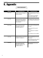
8. Appendix .................................................................................................................................... 70
ERROR MESSAGES ............................................................................................................................ 70
MIDI IMPLEMENTATION ..................................................................................................................... 71
TECHNICAL DATA ................................................................................................................................ 72
REPLIFEX FACTORY PRESETS ..................................................................................................... 73
1. Introduction
Congratulations on your purchase of the Rocktron Replifex guitar effects
processor! The Replifex is a 24-bit DSP processor providing a host of high
quality digital effects, as well as a number of practical features to enhance any
guitar rig.
Preset Spillover allows for reverb and delays from a current preset to
carry over into the next preset and continue decaying when a new
preset has been selected.
Dual Channel Switching allows for programmable channel switching
of amp heads, combo amps or preamps and eliminates the need for a
separate channel switching device.
Real Time Control of delay times and modulation rates through tap
tempo and rate parameters. Delay times and modulation rates can be
changed instantly by tapping either a momentary footswitch or the front
panel Tap Delay/Rate parameter.
High quality digital effects include chorus, delay, auto pan, tremolo,
rotating speaker, pitch shift, flanger, reverb and phaser effects.
HUSH® noise reduction operates only on incoming preamp noise, and
does not affect the digital effects - which are already ultra quiet.
Also provides compression, a four band full parameteric EQ and
complete mixing capabilities.
For a thorough explanation of the Replifex and all its features, please read this
manual carefully and keep it for future reference. After removing the Replifex from
the box, save all the packing materials in case it becomes necessary to ship the unit.
1
2. Quick Setup
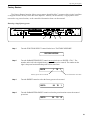
SELECTING A PRESET
STEP 1
Turn the PRESET control to select the desired preset. The new preset will
be recalled automatically.
CHANGING PRESET PARAMETERS
STEP 2
Turn the FUNCTION SELECT control to the desired effect or utility
function.
STEP 3
Turn the PARAMETER SELECT control to the parameter you wish to
alter under the selected effect or utility function.
STEP 4
Use the PARAMETER ADJUST control to select the new parameter
value.
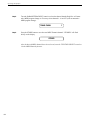
STEP 5
The COMPARE button may be used to compare the sound of the altered
value to the stored value.
STORING CHANGED PARAMETERS
STEP 6
2
After the desired parameters have been edited, press the STORE button
to store the changes into the preset.
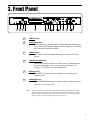
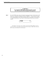
3. Front Panel
1
POWER switch
2
CONFIG button/led
This button briefly displays which configuration the current preset
uses. After displaying the configuration, the Replifex™ will display
the current preset number and title.
3
PRESET control
This control scrolls through and instantly recalls the successive
presets.
4
TAP DELAY/RATE button
This button is used to select a new delay time or modulation rate
based on the length of time occurring between two taps. See
Section 7: "Tap Delay" for more information.
5
DISPLAY panel
The DISPLAY panel provides 16 characters consisting of 14
segments each.
6
COMPARE button
The COMPARE button may be used to compare an altered parameter value to its stored value.
Note:
If comparing an altered value to the stored value and the stored value is currently
being viewed, turning a knob or pressing a button that changes the parameter value
displayed will cancel the previous altered value. This will also occur if a MIDI
control change is received while viewing the stored value(s).
3
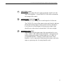
Front Panel Desccription
7
PARAMETER ADJUST control
This control is used to adjust the displayed parameter value. When
the parameter is altered from its stored value, the LED above the
STORE button will light until either (a) the new value is stored, (b)
a new preset is selected or (c) the parameter is returned to its
original value.
8
STORE button/led
This button is used to store parameter values into the Replifex™
memory when altered. See "Storing Changed Preset Parameters" in
Chapter 7 for more information on this procedure.
9
PARAMETER SELECT control
When adjusting parameter values, this control will scroll through
the available parameters under the current function heading.
In the "Title Edit" function, this control will scroll through the
character locations to be edited.
10
FUNCTION SELECT control
This control allows access to each function of the Replifex™. These
functions include:
Global
Mixer
HUSH
Compressor
EQ
11
Delay
Reverb
Tremolo
Phaser
Flanger
Chorus
Pitch Shift
Rotary Speaker
Auto Pan
Speaker Sim
Channel Switches
Title Edit
Controller Assig
Copy
Program Changes
MIDI Channels
MIDI Dump/Load
Factory Restore
Remote Control
Config Select
BYPASS button/led
When lit, the effects are bypassed and only the input signal is
passed to the Replifex™ outputs.
12
INPUT LEVEL meter
These LEDs provide visual indication of the peak level of the input
signal when the preset number and title are displayed. For the
optimal signal-to-noise ratio, it is best to adjust the input level so
that the last LED (0dB) is rarely lit. This will guard against the
possibility of overdriving the unit.
These LEDs also display the final digital mixer output levels when
any other functions are displayed. This will help you to guard
against clipping the output of the mixer at the digital-to-analog
converter.
4
Front Panel DescriptionOperating the Replifex™ Operating the Replifex™
13
INPUT LEVEL control
This control adjusts the unit’s gain to match the signal level at the
input of the Replifex™. Use the INPUT LEVEL meter to determine
the setting of this control.
14
OUTPUT LEVEL control and CLIP LED
This control is used to adjust the overall output level of the unit.
The CLIP L.E.D. is part of the output section and, when lit, indicates
that the final analog output is being overdriven due to the Effects
Level, Direct Level and Output Level being set too high. If this
should occur, reduce these levels until the L.E.D. does not light.
15
REFERENCE LEVEL switch
This switch adjusts the output range of the unit and may be set at
either -10dB or +4dB. When using the Replifex™ with professional
studio equipment providing a nominal input level of +4dB, it is
recommended that the +4 setting is used for best results. If the
Replifex™ is to be connected to a high sensistivity input, such as the
input to a guitar amp, the -10 setting should be used.
5
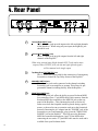
4. Rear Panel
1
Left and Right INPUT jacks
These ¼" mono jacks provide inputs to the left and right channels
of the Replifex™. When using only one input, the Right (R) jack
should be used.
2
Left and Right OUTPUT jacks
These ¼" mono jacks provide outputs from the left and right
channels of the Replifex™.
When using a mono input (Right channel INPUT jack) and a mono
output (either OUTPUT jack), the left and right effected signals
will be summed at the single output.
3
Tap Delay/Rate FOOTSWITCH jack
This ¼" mono jack is provided for the connection of a momentary
footswitch to control the Tap Delay feature of the Replifex™.
4
CHANNEL SWITCH jack
This ¼" stereo jack can be connected to the channel switching
footswitch jack on an amplifier or preamp. This allows for programmable channel switching directly from the Replifex™.
.
5
PHANTOM POWER jack
This 2.5mm PIN jack offers the ability to power Rocktron MIDI
foot controllers from a 7-pin MIDI cable which connects from the
Rocktron MIDI foot controller to the MIDI IN jack on the rear
panel of the Replifex™. This eliminates the need to find an AC
outlet near where the footpedal would be placed during a performance, or the need to run an extension cord out to the footswitch.
Instead of inserting the AC adaptor into the "POWER" jack of the
footswitch as you would normally, plug it into the "PHANTOM
POWER" jack on the Replifex™. This will power the Rocktron
MIDI foot controller through pins 6 and 7 of the MIDI cable
connecting the two units. A 7-pin MIDI cable must be used and is
available from your Rocktron dealer.
6
Rear Panel Description
6
MIDI IN/REMOTE jack
This 7-pin DIN connector must be connected to the MIDI OUT
jack of the transmitting MIDI device via a standard MIDI cable, or
to the MIDI THRU jack of the preceding MIDI device (if the
Replifex™ is within a chain of MIDI devices). Pins 6 and 7 of this
connector carry phantom power to power a Rocktron MIDI foot
controller when a 7-pin MIDI cable is used.
This connector is also provided for the connection of a Rocktron
All Access™ MIDI footswitch, which can be configured as a
dedicated remote footswitch for the Replifex™. This feature allows
the user to access Replifex™ functions and parameters via the
remote footswitch.
7
MIDI THRU/OUT jack
This standard 5-pin DIN connector can be connected to the MIDI
IN jack of another device via a standard MIDI cable. There are
limitations to the number of devices that can be chained (or series
connected) in this fashion.
Note: Inherently in MIDI there is a limit to the number of devices which
can be chained together (connected in series). With more than 3 devices,
a slight distortion of the MIDI signal can occur (due to signal degradation)
which can cause an error in MIDI signal transmission. Should this problem arise, a MIDI Thru box can be used which connects directly to the
MIDI device which transmits MIDI information and has multiple connectors for the multiple devices receiving MIDI. MIDI cables should not
exceed 50 feet (15 meters) in length.
8
POWER jack
This 2.5mm pin jack accepts power from the 9VAC adaptor supplied with the unit.
7
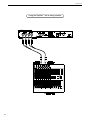
5. Connections
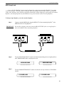
Using the Replifex within a guitar rack system
8
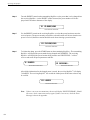
Using the Replifex in a preamp effects loop
9
Connections
Using the Replifex with a mixing console
10
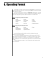
6. Operating Format
The Replifex provides 128 stored sounds called presets. Any of the 128 presets can be called up at any time via the front panel PRESET control (used to both
select and recall a preset).
The root of each presets sound is its configuration. The Replifex provides
two main effect configurations - the Classic configuration and the Rotary configuration. Each configuration provides a different selection of available effects.
Classic configuration provides these effects:
•
•
•
•
HUSH®
Parametric EQ
Flanger
Chorus
•
•
•
•
Reverb
Compression
Tremolo
Auto Pan
•
•
•
•
Delay
Phaser
Pitch Shift
Speaker Simulator
Rotary configuration provides these effects:
• HUSH®
• Parametric EQ
• Rotary Speaker
• Reverb
• Compression
• Speaker Simulator
• Delay
Any of the effects provided within a particular configuration may be
switched in or out for each preset.
To see which configuration a given preset is utilizing, press the CONFIG
button on the front panel of the Replifex - the display will show which configuration ("Classic" or "Rotary") is active for the current preset. The configuration
type is displayed for a few seconds before returning to the current preset number
and title.
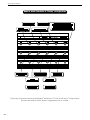
The block diagrams on pages 12 and 13 illustrate the basic signal path for
each configuration.
11
Block Diagrams
Classic Configuration
Block Diagram
12
Block Diagrams
Rotary Configuration
Block Diagram
13
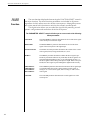
Functions and Parameter Descriptions
Replifex™ Functions and Parameter Descriptions
Each Replifex preset is divided into individual blocks called functions (such
as "Mixer", "Reverb", etc.). Within each function is a set of controls which allow you
to manipulate various aspects of that function. These controls are called parameters. The setting of each of the parameters determines the overall sound of each
Replifex preset.
The Replifex user interface is set up to allow you to first access each function
(via the FUNCTION SELECT control), then the list of available parameters for the
selected function (via the PARAMETER SELECT control) and, finally, the adjustable
value for each parameter (via the PARAMETER ADJUST control).
Step 3:
Turn to alter the value of the
selected parameter.
Step 2:
Turn to select a parameter
within the selected function.
Step 1:
Turn to select a function.
The remainder of this section will discuss each of the effect-based functions
and the associated adjustable parameters that they provide. Functions not discussed in this section are utility-based, and are described in Section 7, "Operating
the Replifex".
14
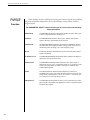
Functions and Parameter Descriptions
GLOBAL
Function
The first function displayed when turning the FUNCTION SELECT control is
the Global function. The parameters provided in this function affect all presets
(i.e. the settings stored for these parameters are the same for all presets).
The PARAMETER SELECT control will allow you to access each of the following
Global parameters:
OUTPUT
The OUTPUT parameter determines whether the output of the
Replifex™ is a stereo (left and right) signal or two mono signals.
HUSH OFFSET
The HUSH OFFSET parameter allows you to globally (all presets)
adjust the HUSH® Expander Threshold. This means that if this parameter is altered from 0dB to +3dB, the Expander Threshold will be 3dB
higher for all presets. This feature can be useful when switching from a
quiet guitar with passive electronics to a noisy guitar with active
electronics - as the active guitar would require a higher Threshold level
in all presets.
MUTE
The MUTE parameter allows you to mute the output of the Replifex™.
This feature is especially useful when changing guitars during a live set.
When the Replifex is muted, front panel controls are disabled. However,
a MIDI program change will disable the mute (mute = out) and execute
the program change.
The MUTE parameter can be assigned to a MIDI controller number for
use with a MIDI device (such as a Rocktron All Access™ or Rocktron
MIDI Mate™).
DIRECT
The DIRECT parameter determines whether the direct signal is
switched in or out of the signal path. When using the Replifex™ in
applications where the unit is connected in parallel, it is recommended
that the direct signal is switched out - thereby providing 100% wet
(effect) output.
15
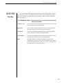
Functions and Parameter Descriptions
MIXER
Function
The next function displayed when turning the FUNCTION SELECT control is
the Mixer function. The Mixer function parameters are included in all presets regardless of which effects are active for the current preset - although the parameter values stored in this function are only for the currently recalled preset.
This digital mixer allows you to control the signal levels pertaining to each
presets configuration and stores those levels for each preset.
The PARAMETER SELECT control will allow you to access each of the following
Mixer parameters:
16
LEFT DIR
The LEFT DIRECT parameter determines the level of the direct signal
of the current preset at the left output.
RIGHT DIR
The RIGHT DIRECT parameter determines the level of the direct
signal of the current preset at the right output.
EFFECT LEVEL
The EFFECT LEVEL parameter determines the volume of the overall
effect signal (Chorus, Flange, Pitch Shift, etc.) level.
DIRECT
The DIRECT parameter determines whether the direct signal is preHUSH or post-HUSH. When set to pre-HUSH, the direct signal is not
passed through the HUSH circuitry, or any other digital circuitry (i.e.,
the direct signal remains analog from input to output. When set to postHUSH, the direct signal is passed through the digital HUSH circuitry.
PHS DIR/EFF
CHR DIR/EFF
FLN DIR/EFF
REV DIR/EFF
These DIR/EFF parameters determine the amount of direct signal input
to each individual effect relative to the amount of effect signal. A
setting of "0" is 100% direct signal, while a setting of "100" is 100%
effect signal.
VOLUME
The VOLUME parameter determines the overall signal level of the
current preset.
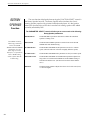
Functions and Parameter Descriptions
HUSH
Function
The HUSH® function is accessible in all presets - regardless of the configuration currently recalled.
HUSH® is Hush Systems patented single-ended noise reduction system. The
HUSH system contained in the Replifex is a fully digital implementation of
HUSH achieved through Digital Signal Processing (DSP), and is modeled after the
latest HUSH design.
The low level expander of the HUSH system operates like an electronic
volume control. The analog version of the HUSH utilizes a voltage-controlled
amplifier (VCA) circuit which can control the gain between the input and the
output from unity to 30, 40 or even 50dB of gain reduction. When the input
signal is above the user preset threshold point, the VCA circuit remains at unity
gain. (This means that the amplitude of the output signal will be equal to that of
the input signal.) As the input signal level drops below the user preset threshold
point, downward expansion begins. At this point the expander acts like an electronic volume control and gradually begins to decrease the output signal level
relative to the input signal level. As the input signal drops further below the
threshold point, downward expansion increases. A drop in the input level by
20dB would cause the output level to drop approximately 40dB (i.e., 20dB of gain
reduction). In the absence of any input signal, the expander will reduce the gain
so that the noise floor becomes inaudible.
The HUSH circuit is located after the A/D converter in the signal chain to
reduce any noise generated from the guitar, any guitar preamp and the A/D
converter. This ensures a quiet input signal to the Replifex effects.
When the DIRECT HUSH parameter under the Mixer function is set to "Post",
the direct signal is passed through the HUSH circuit. When set to "Pre", the direct
signal remains analog and does not pass through the HUSH circuit.
The PARAMETER SELECT control will allow you to access each of the following
Hush parameters:
HUSH I/O
The HUSH I/O parameter determines whether the HUSH® circuit is
active or bypassed for the current preset.
EXP THRESH
The EXPANDER THRESHOLD parameter determines the level at
which downward expansion begins. For example, if the EXPANDER
THRESHOLD was set at -20dB and the input signal dropped below
-20dB, downward expansion would begin.
17
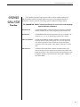
Functions and Parameter Descriptions
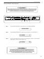
COMPRESSOR
Function
18
Compression is often used to maintain an even level when using clean tones,
and is also used to increase sustain when using high gain distortion.
The PARAMETER SELECT control will allow you to access each of the following
Compressor parameters:
COMPRESR I/O
The COMPRESSOR I/O parameter determines whether the compression circuit is active or bypassed for the current preset.
COMP THRESH
The COMPRESSOR THRESHOLD parameter determines the input
level (in dB) at which compression will begin. Lower settings of this
parameter will result in more compression.
COMP ATTACK
The COMPRESSOR ATTACK parameter determines the speed (in
milliseconds) at which the compressor will reach its maximum compression level after the input signal has exceeded the threshold level (set
by the COMPRESSOR THRESHOLD parameter).
COMP RELEASE
The COMPRESSOR RELEASE parameter determines the speed at
which compression will cease after the input signal has dropped below
the threshold level.
Functions and Parameter Descriptions
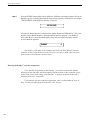
EQ
Function
The EQ function provides full parametric control and allows you shape the
tone of the input signal before it reaches each of the effect blocks.
The PARAMETER SELECT control will allow you to access each of the following
EQ parameters:
EQ I/O
The EQ I/O parameter determines whether the EQ circuit is active or
bypassed for the current preset.
BASS LVL
The BASS LEVEL parameter allows you to cut or boost the low
frequencies by up to 15dB.
BASS FREQ
The BASS FREQUENCY parameter allows you to select a center
frequency between 63Hz and 500Hz to be cut or boosted by the BASS
LEVEL parameter.
BASS BW
The BASS BANDWIDTH parameter determines (in octaves) the width
of the selected bass band.
MID LVL
The MID LEVEL parameter allows you to cut or boost the mid band
frequencies by up to 15dB.
MID FREQ
The MID FREQUENCY parameter determines a mid band center
frequency between 250Hz and 2KHz to be cut or boosted via the MID
LEVEL parameter.
MID BW
The MID BANDWIDTH parameter determines (in octaves) the width
of the selected mid band.
TREBLE LVL
The TREBLE LEVEL parameter allows you to cut or boost the high
band frequencies by up to 15dB.
TREBL FRQ
The TREBLE FREQUENCY parameter determines a high band center
frequency between 1KHz and 8KHz to be cut or boosted via the
TREBLE LEVEL parameter.
TREBLE BW
The TREBLE BANDWIDTH parameter determines (in octaves) the
width of the selected high band.
PRESENCE LVL
The PRESENCE LEVEL parameter allows you to cut or boost an
additional high band frequency by up to 15dB.
PRES FREQ
The PRESENCE FREQUENCY parameter allows you to select a high
band center frequency between 2KHz and 8KHz to be cut or boosted
via thePRESENCE LEVEL parameter.
PRES BW
The PRESENCE BANDWIDTH parameter determines (in octaves) the
width of the selected high band.
19
Functions and Parameter Descriptions
DELAY
Function
Delay provides a reproduction of the input signal, occurring at a prescribed
time (usually expressed in milliseconds) following the input signal. The Replifex
provides two discrete delays (Delay 1 and Delay 2), each of which has its own set
of parameters to determine its particular characteristics.
The PARAMETER SELECT control will allow you to access each of the following
Delay parameters:
DELAY I/O
The DELAY I/O parameter determines whether the delay circuit is
active or bypassed for the current preset.
MUTE TYPE
The MUTE TYPE parameter allows for muting the delay at its input
(PRE), its output (POST) or BOTH.
Muting the input (PRE) of the delay will not allow any signal to enter
the delay section until the delay is switched in. When using a moderate
amount of regeneration, switching out the delay with the input muted
will allow you to generate a non-delayed signal which will play over the
decaying regenerated signal which continues on after the delay is
switched out.
Muting the output (POST) of the delay will result in the delayed signal
being immediately turned off when the delay is switched out. This
means that delays and regeneration will not continue when the delay is
switched out. If the output were not muted, signals that were input
before the delay was switched out would be allowed to regenerate, even
after switching out the delay.
It is also possible to mute both the input and the output (BOTH) so that
no signal enters or exits the Delay section until it is switched in.
20
TIME1
The TIME1 parameter determines the multiplier by which a new delay
time will be selected for Delay Time 1 when the Tap Delay feature of
the Replifex™ is used. (See Section 7: "Tap Delay" for more information
on the Tap Delay feature.)
TIME2
The TIME2 parameter determines the multiplier by which a new delay
time will be selected for Delay Time 2 when the Tap Delay feature of
the Replifex™ is used. (See Section 7: "Tap Delay" for more information
on the Tap Delay feature.)
DELAY LVL
The DELAY LEVEL parameter determines the overall level of the
delayed signal at the output of the Replifex™ .
D-MIX S1/S2
The D-MIX S1/S2 parameter defines the ratio of Source 1 signal to
Source 2 signal to be input to the Delay section. Source 1 is the Voice 1
output from the previous effect in the signal chain (chorus, flanger,
pitch shifter, etc.), while Source 2 may be the Voice 2 output from the
previous effect in the signal chain or the direct signal (selectable via the
SOURCE 2 parameter). (Refer to the block diagrams shown on pages
12 and 13 for a visual representation of the input to the Delay section.)
Functions and Parameter Descriptions
SOURCE 2
This parameter is used to select whether the Source 2 input will be the
VOICE 2 output from the previous effect in the signal chain or the
direct signal. In configurations where there is no effect immediately
preceding the delay, both Source 1 and Source 2 will be the direct
signal.
DLY HF DAMP
The DELAY HIGH FREQUENCY DAMPING parameter controls the
amount of high frequency content in the delayed and regenerated
signals. Higher amounts of damping will result in less high frequency
information in the delayed signal.
DELAY OUT 1
The DELAY OUT 1 parameter determines the volume of Delay 1.
When delays from the
current preset are spilled
over into the next preset
recalled (i.e. SPILLOVER
"ON"), the delay parameters
for the new preset will be
changed to match those of
the previous preset (except
for the DELAY I/O and
SPILLOVER parameters) even if the Delay effect is
switched "OUT" in the
previous preset.
DLY PAN1
The DLY PAN1 parameter allows you to pan the Delay 1 signal to the
left or right channel.
DLY TIME1
The DELAY TIME1 parameter determines the length of time (in
milliseconds) after the input signal that the Delay 1 signal will begin.
The DELAY TIME can be adjusted via the PARAMETER ADJUST
control, MIDI controller changes or via the Tap Delay feature.
FINE 1
The FINE 1 parameter allows for adjustment of Delay 1 in 1 millisecond increments.
DLY RGN 1
The DLY RGN 1 parameter determines how many times the Delay 1
signal is fed back into the input and repeated.
The EFFECT LEVEL
parameter in the next preset
recalled does not change,
therefore delays spilled into
it may be of higher or lower
volume - depending on the
EFFECT LEVEL setting in
each preset.
DELAY OUT 2
The DELAY OUT 2 parameter determines the volume of Delay 2.
DLY PAN2
The DLY PAN2 parameter allows you to pan the Delay 2 signal to the
left or right channel.
DLY TIME2
The DELAY TIME2 parameter determines the length of time (in
milliseconds) after the input signal that the Delay 2 signal will begin.
The DELAY TIME can be adjusted via the PARAMETER ADJUST
control, MIDI controller changes or via the Tap Delay feature.
FINE 2
The FINE 2 parameter allows for adjustment of Delay 2 in 1 millisecond increments.
DLY RGN 2
The DLY RGN 2 parameter determines how many times the Delay 2
signal is fed back into the input and repeated.
D>SPILLOVER
The SPILLOVER parameter determines whether delays from the
current preset will "spill over" into the next preset when it is recalled.
!
Note!
Also, recalling the same
preset twice via MIDI will
cancel the Spillover effect
and reset the new preset to
its stored parameter values
(only when the SPILLOVER
parameter in the recalled
parameter is set "OFF").
21
Functions and Parameter Descriptions
REVERB
Function
!
Reverb is a multitude of echos spaced so close together that, to the human
ear, seem as a single continuous sound. These echos gradually decrease in
intensity until they are ultimately absorbed by the boundaries and obstacles
within a room. As the sound waves from the sound source strike the boundaries
of a room, a portion of the energy is reflected away from the obstacle while
another portion is absorbed into it - thereby causing both the continuance of
sound as well as the decaying or dying out of the sound.
The PARAMETER SELECT control will allow you to access each of the following
Reverb parameters:
Note!
When reverb from the
current preset is spilled
over into the next preset
recalled (SPILLOVER
"ON"), the reverb
parameters for the new
preset will be changed to
match those of the previous
preset (except for the REV
INPUT and SPILLOVER
parameters) - even if the
Reverb effect itself is
switched "OUT" in the
previous preset.
The EFFECT LEVEL
parameter in the next preset
recalled does not change,
therefore reverb spilled into
it may be of higher or lower
volume - depending on the
EFFECT LEVEL setting in
each preset.
Also, recalling the same
preset twice via MIDI will
cancel the Spillover effect
and reset the new preset to
its stored parameter values
(only when the SPILLOVER
parameter in the recalled
parameter is set "OFF").
22
REV INPUT
The REV INPUT parameter determines whether the reverb circuit is
active or bypassed for the current preset.
R-MIX EFF/DLY
The R-MIX EFFECT/DELAY parameter is used to define the ratio of
direct signal to delayed signal to be input to the reverb section.
REVERB LVL
The REVERB LEVEL parameter allows you to control the level of the
reverb signal at the output of the Replifex™ relative to the direct signal
and other effect signals.
REV DECAY
The REVERB DECAY parameter determines the length of time that the
reverb signal will sound before it has completely died out.
REV HF DAMP
The REVERB HIGH FREQUENCY DAMPING parameter is used to
control the decay rate of high frequency information in the reverb
signal. Higher parameter settings will result in a faster decay of high
frequency information.
R>SPILLOVER
The R>SPILLOVER parameter determines whether reverbs generated
in the current preset will continue decaying when the next preset is
recalled.When switched off, reverbs will be abrubtly cut off when the
next preset is recalled.
Functions and Parameter Descriptions
TREMOLO
Function
The Tremolo effect continuously varies the volume of the signal.
The PARAMETER SELECT control will allow you to access each of the following
Tremolo parameters:
TREMOLO I/O
The TREMOLO I/O parameter determines whether the tremolo circuit
is active or bypassed for the current preset.
LOCATION
The LOCATION parameter determines whether the Tremolo is located
Pre-Reverb or Post-Reverb. Most vintage amplifiers used the tremolo in
a Post-Reverb configuration.
TREM DPTH
The TREMOLO DEPTH parameter determines the amount of modulation for the Tremolo signal. Lower DEPTH settings produce more
subtle tremolo effects, while higher settings will result in a more
extreme tremolo effect.
TREM RATE
The TREMOLO RATE parameter determines the speed at which the
tremolo signal modulates (or increases and decreases in volume).
SHAPE
The SHAPE parameter determines the waveshape of the tremolo signal.
Selecting a different waveshape produces a different tremolo effect.
TIME
The TIME parameter determines the multiplier by which a new
modulation rate will be selected for the RATE parameter when the Tap
Delay feature of the Replifex™ is used. (See Section 7: "Tap Delay" for
more information on the Tap Delay feature.)
23
Functions and Parameter Descriptions
PHASER
Function
Phase shifting involves splitting the input signal into two signals, then shifting
the phase of different frequencies of one signal before mixing it back with the
original signal.
The PARAMETER SELECT control will allow you to access each of the following
Phaser parameters:
24
PHASER I/O
The PHASER I/O parameter determines whether the phase shift circuit
is active or bypassed for the current preset.
PSR PAN
The PHASER PAN parameter allows you to pan the phase shifted
signal to the left or right channel by any amount.
PSR DEPTH
The PHASER DEPTH parameter determines the modulation depth of
the phase shift effect. Higher parameter settings result in the sweep of
the filtering effect occurring over a wider frequency range.
RATE
The RATE parameter determines the speed at which the phase shifted
signal is modulated.
P>RESONANCE
The PHASER RESONANCE parameter adds feedback to the Phaser so
that it has a more pronounced effect.
PSR STAGES
The PHASER STAGES parameter determines how many stages of
phase shift are to be active. A parameter setting of "4" produces a result
similar to a vintage Phase 90, while a setting of "6" emulates other
common phaser pedals.
TIME
The TIME parameter determines the multiplier by which a new
modulation rate will be selected for the RATE parameter when the Tap
Delay feature of the Replifex™ is used. (See Section 7: "Tap Delay" for
more information on the Tap Delay feature.)
PHASER LVL
The PHASER LEVEL parameter allows you to control the level of the
phaser signal at the output of the Replifex™ relative to the direct signal
and other effect signals.
Functions and Parameter Descriptions
FLANGER
Function
Flanging splits the input signal into two individual delayed signals (Voice 1
and Voice 2), then modulating the delayed signals so that, when summed back
with the direct signal, phase cancellations will occur at some frequencies while
peaks in the response will occur at others.
The PARAMETER SELECT control will allow you to access these FLANGER parameters:
FLANGER I/O
The FLANGER I/O parameter determines whether the flange circuit is
active or bypassed for the current preset.
FLN OUT 1
The FLANGER OUTPUT 1 parameter determines the overall volume
of Voice 1.
FLN PAN1
The FLANGER PAN 1 parameter allows you to pan Voice 1 to the left
or right channel.
FLN DPTH 1
The FLANGER DEPTH 1 parameter adjusts the amount of modulation
of Voice 1. Lower DEPTH settings produce more subtle effects, while
higher settings will result in a more drastic effect.
FLN RATE 1
The FLANGER RATE 1 parameter determines the speed at which
Voice 1 is modulated.
TIME1
The TIME1 parameter determines the multiplier by which a new
modulation rate will be selected for the RATE 1 parameter when the
Tap Delay feature of the Replifex™ is used. (See Section 7: "Tap Delay"
for more information on the Tap Delay feature.)
FLN OUT 2
The FLANGER OUTPUT 2 parameter determines the overall volume
of Voice 2.
FLN PAN2
The FLANGER PAN 2 parameter allows you to pan Voice 2 to the left
or right channel.
FLN DPTH 2
The FLANGER DEPTH 2 parameter adjusts the amount of modulation
of Voice 2. Lower DEPTH settings produce more subtle effects, while
higher settings will result in a more drastic effect.
FLN RATE 2
The FLANGER RATE 2 parameter determines the speed at which
Voice 2 is modulated.
TIME2
The TIME2 parameter determines the multiplier by which a new
modulation rate will be selected for the RATE 2 parameter when the
Tap Delay feature of the Replifex™ is used. (See Section 7: "Tap Delay"
for more information on the Tap Delay feature.)
FLN REGEN
The FLANGER REGENERATION parameter determines how much of
the the delayed output signal is fed back into the input. More regeneration produces a more pronounced "jet airplane" type of effect.
25
Functions and Parameter Descriptions
CHORUS
Function
The Chorus effect in the Replifex is produced by detuning two delayed
signals (Voice 1 and Voice 2), then modulating the detune effect so that the
amount of pitch detune is constantly varying. Using different detune amounts,
modulation rates, modulation depths and pan settings for each delayed signal will
produce a greater perceived spaciousness.
The PARAMETER SELECT control will allow you to access each of the following
Chorus parameters:
26
CHORUS I/O
The CHORUS I/O parameter determines whether the chorus circuit is active or
bypassed for the current preset.
CRS OUT 1
The CHORUS OUTPUT 1 parameter determines the volume of Voice 1.
CRS PAN 1
This parameter allows you to pan Voice 1 to the left or right channel.
CRS DPTH 1
The CHORUS DEPTH 1 parameter adjusts the amount of modulation of the
Voice 1 signal. A lower depth setting will produce a more subtle detune effect,
while a higher setting results in a more extreme detuning of Voice 1.
CRS RATE 1
The CHORUS RATE 1 parameter determines the sweep speed (or the speed at
which Voice 1 is modulated).
CRS>DLY1
This parameter allows you to select the minimum delay time (in milliseconds)
for Voice 1. This delayed signal (along with Voice 2) is detuned and modulated
to produce the chorus effect. Using shorter delay times will result in a tighter
sounding chorused signal, while longer delay times will produce a larger
ambient effect.
TIME1
The TIME 1 parameter determines the multiplier by which a new modulation
rate will be selected for the RATE 1 parameter when the Tap Delay feature of
the Replifex™ is used.
CRS OUT 2
The CHORUS OUTPUT 2 parameter determines the volume of Voice 2.
CRS PAN 2
This parameter allows you to pan Voice 2 to the left or right channel.
CRS DPTH 2
The CHORUS DEPTH 2 parameter adjusts the amount of modulation of the
Voice 2 signal. A lower depth setting will produce a more subtle detune effect,
while a higher setting will produce a more extreme detuning of Voice 2.
CRS RATE 2
The CHORUS RATE 2 parameter determines the sweep speed (or the speed at
which Voice 2 is modulated).
CRS>DLY 2
This parameter allows you to select the minimum delay time (in milliseconds)
for Voice 2. This delayed signal (along with Voice 1) is detuned and modulated
to produce the chorus effect. Using shorter delay times will result in a tighter
sounding chorused signal, while longer delay times will produce a larger
ambient effect.
TIME2
The TIME 2 parameter determines the multiplier by which a new modulation
rate will be selected for the RATE 2 parameter when the Tap Delay feature of
the Replifex™ is used. (See Section 7: "Tap Delay" for more information on the
Tap Delay feature.)
Functions and Parameter Descriptions
PITCH
SHIFT
Function
Pitch Shifting is used to change the pitch of the input signal to produce a
harmony note based on the input signal. The harmony voice may be of any fixed
interval - up to one octave above the input signal to two octaves below - and is
selected in 20-cent increments. Fine adjustment can be made in one cent (1/100th
semitone) increments.
The PARAMETER SELECT control will allow you to access each of the following
Pitch Shift parameters:
PITCH SH I/O
The PITCH SHIFT I/O parameter determines whether the pitch shift
circuit is active or bypassed for the current preset.
PSHIFT OUT
The PITCH SHIFT OUTPUT parameter determines the volume of the
pitch shifted signal. The DIR/EFF MIX parameter in the Mixer function
also affects this volume.
PS PAN
The PITCH SHIFT PAN parameter allows you to pan the shifted signal
to the left or right channel.
PITCH
The PITCH parameter selects what harmony note the Replifex™ will
produce based on the input note. The value displayed for this parameter
represents the number of cents that the signal will be shifted (adjustable
in 20-cent increments). Each 100 cents (or five 20-cent steps) above or
below "0" represents the number of half-steps the shifted signal will be
from the input signal.
This parameter is adjustable from "-2400" to "+1200", where "-2400" =
two octaves below the input signal, "0" = unison and "+1200" = one
octave above the input signal. Refer to the table on the following page
to determine the cent value for each fixed interval.
FINE
The FINE parameter allows for adjustment in l-cent steps for fine
adjustment of the harmony note.
PS-SPEED
The PITCH SHIFT SPEED parameter determines the amount of time
delay used in the shifting process. SLOW results in the longest delay
and the highest quality shifted signal (especially at larger amounts of
pitch shift). FAST results in the least delay, but the lowest quality
shifted signal. This setting should only be used for slight amounts of
pitch shift.
27
Functions and Parameter Descriptions
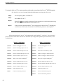
PITCH SHIFT INTERVALS
PARAMETER CORRESPONDING
VALUE INTERVAL
+1200
+1100
+1000
+900
+800
+700
+600
+500
+400
+300
+200
+100
0
-100
-200
-300
-400
-500
-600
-700
-800
-900
-1000
-1100
-1200
-1300
-1400
-1500
-1600
-1700
-1800
-1900
-2000
-2100
-2200
-2300
-2400
NOTE:
28
one octave
Major 7th
minor 7th
Major 6th
minor 6th
perfect 5th
diminished 5th
perfect 4th
Major 3rd
minor 3rd
Major 2nd
minor 2nd
Unison
Major 7th
minor 7th
Major 6th
minor 6th
perfect 5th
diminished 5th
perfect 4th
Major 3rd
minor 3rd
Major 2nd
minor 2nd
1 Octave
One octave plus a Major 7th
One octave plus a minor 7th
One octave plus a Major 6th
One octave plus a minor 6th
One octave plus a perfect 5th
One octave plus a diminished 5th
One octave plus a perfect 4th
One octave plus a Major 3rd
One octave plus a minor 3rd
One octave plus a Major 2nd
One octave plus a minor 2nd
2 Octaves
Voices above the input signal
Equal to the input signal
Voices below the
input signal
There are 5 steps of the parameter adjust control between each of the intervals shown above (each step
equals 20 cents).This allows for smooth pitch change when an expression controller (such as a volume
pedal used with a Rocktron All Access™ or MIDI Mate™ foot controller) is assigned to the PITCH
parameter to change the pitch by remote means.
Functions and Parameter Descriptions
AUTO PAN
Function
The next function displayed when turning the FUNCTION SELECT control is
the Auto Pan function. The Auto Pan effect auomatically pans between left and
right when operating in stereo mode. (If operating in mono, the Auto Pan effect
does not operate.)
The PARAMETER SELECT control will allow you to access each of the following
Auto Pan parameters:
AUTO PAN I/O
The AUTO PAN I/O parameter determines whether the auto pan circuit
is active or bypassed for the current preset.
LOCATION
The LOCATION parameter determines what part of the signal path is
affected by Auto Pan - Direct Only, Effects Only or Both.
APAN RATE
The AUTO PAN RATE parameter determines the speed at which the
signal is panned between the Left and Right channels.
APAN WIDTH
The AUTO PAN WIDTH parameter determines the intensity at which
the signal is panned between the Left and Right channels.
TIME
The TIME parameter determines the multiplier by which a new
modulation rate will be selected for the RATE parameter when the Tap
Delay feature of the Replifex™ is used. (See Section 7: "Tap Delay" for
more information on the Tap Delay feature.)
29
Functions and Parameter Descriptions
ROTARY
SPEAKER
Function
The next function displayed when turning the FUNCTION SELECT control is
the Rotary Speaker function. The Rotary Speaker effect simulates the classic
rotating speaker popular with guitarists and keyboard players. It is designed to
mimic the characteristics of the classic mechanical rotating speaker with added
versatility afforded by DSP.
The PARAMETER SELECT control will allow you to access each of the following
Rotary Speaker parameters:
*For added versatility
when using continuous
control, the SLOW
SPEED and FAST SPEED
parameters cover the
same range (0 to 100).
Therefore, it is possible to
have a SLOW setting
which is faster than the
FAST setting.
30
ROTR SPK I/O
The ROTR SPK I/O parameter determines whether the simulated
speaker is rotating or not.
ROT SPEED
The ROTATION SPEED parameter switches between the SLOW
SPEED and FAST SPEED setting..
R>SPKR SLOW*
The ROTARY SPEAKER SLOW parameter sets the slow rotation
speed. (The horn and rotor will rotate at slightly different speeds.)
R>SPKR FAST*
The ROTARY SPEAKER FAST parameter sets the fast rotation speed.
ROT SPK ACCEL
The ROTARY SPEAKER ACCELERATION parameter adjusts how
long it takes to reach the FAST SPEED or SLOW SPEED setting of
both the horn and the rotor. (The horn will accelerate faster than the
rotor.)
ROT BAL
The BALANCE parameter adjusts the relative level of the rotor (lows)
vs. the horn (highs).
Functions and Parameter Descriptions
SPEAKER
SIMULATOR
Function
The Speaker Simulator function provides a realistic approximation of a
miked speaker cabinet for applications involving connecting the Replifex
directly to a mixing console, recording system or other full range system.
The PARAMETER SELECT control will allow you to access each of the following
Speaker Simulator parameters:
SPKR SIM I/O
The SPEAKER SIMULATOR I/O parameter determines whether the
speaker simulator circuit is active or bypassed for the current preset.
SPKR TYPE
The SPEAKER TYPE parameter determines the type of speaker to be
simulated. 15", 12" 10", 8" and full range speakers are available.
MIC PLACEMENT
The MIC PLACEMENT parameter simulates a microphone placed
anywhere from the center of the speaker cone out to the edge of the
cone. Positive parameter values simulate moving the microphone
toward the center of the speaker, while negative values move it to the
edge.
REACTANCE
The REACTANCE parameter simulates the characteristics of the
interaction between a tube amplifier and a guitar speaker cabinet. The
higher the parameter value selected, the more these characteristics will
be apparent. Negative values of reactance can be used to simulate an
open-back cabinet.
31
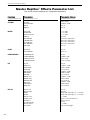
Functions and Parameter Ranges
Master Replifex Effects Parameter List
(The actual functions displayed are configuration-dependent)
Function
Parameter
Parameter Range
GLOBAL
OUTPUT
HUSH OFFSET
MUTE
DIRECT
Stereo, Mono
-10dB to +30dB
Out, In
Out, In
MIXER
LEFT DIR
RIGHT DIR
EFFECT LEVEL
DIRECT
PHS DIR/EFF
CHR DIR/EFF
FLN DIR/EFF
REV DIR/EFF
VOLUME
-∞ to +6dB
-∞ to +6dB
-∞ to +6dB
Pre, Post
Direct<0 to 100>Effect
Direct<0 to 100>Effect
Direct<0 to 100>Effect
Direct<0 to 100>Effect
0 to 127
HUSH
HUSH I/O
EXP THRESH
Out, In
-90 to -27
COMPRESSOR
COMPRESR I/O
COMP THRESH
COMP ATTACK
COMP RELEASE
In, Out
-30dB to -6dB
1ms to 75ms
.05 to 2 seconds
EQ
EQ I/O
BASS LVL
BASS FREQ
BASS BW
MID LEVEL
MID FREQ
MID BW
TREBL LVL
TREBL FRQ
TREBLE BW
PRES LVL
PRES FREQ
PRES BW
Out, In
-15dB to +15dB
63Hz to 500Hz
.2 to 2 octaves
-15dB to +15dB
250Hz to 2kHz
.2 to 2 octaves
-15dB to +15dB
1kHz to 8kHz
.2 to 2 octaves
-15dB to +15dB
2kHz to 8kHz
.2 to 2 octaves
DELAY
DELAY I/O
MUTE TYPE
TIME1
TIME2
DELAY LVL
D-MIX S1/S2
SOURCE 2
DLY HF DAMP
DELAY OUT 1
DLY PAN1
Out, In
Pre, Post
32nd, 16th, 8th, Triplet, ¼, ½, or None
32nd, 16th, 8th, Triplet, ¼, ½, or None
-∞ to 0dB
Source 1<0 to 100>Source 2
Direct, Voice 2
0 to 99
-∞ to 0dB
Left<0 to 100>Right
(via FUNCTION SELECT control)
32
(via PARAMETER SELECT control)
(via PARAMETER ADJUST control)
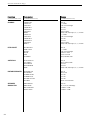
Functions and Parameter Ranges
Function
Parameter
Range
DLY TIME1
FINE 1
DLY RGN 1
DELAY OUT 2
DLY PAN2
DLY TIME2
FINE 2
DLY RGN 2
D>SPILLOVER
0ms to 1000ms
0ms to 9ms
-∞ to 0dB
-∞ to 0dB
Left<0 to 100>Right
0ms to 1000ms
0ms to 9ms
-∞ to 0dB
Off, On
REVERB
REV INPUT
R-MIX EFF/DLY
REVERB LVL
REV DECAY
REV HF DAMP
R>SPILLOVER
Muted, Active
Effect<0 to 100>Delay
-∞ to 0dB
0 to 99
0 to 99
Off, On
TREMOLO
TREMOLO I/O
LOCATION
TREM DPTH
TREM RATE
SHAPE
TIME
Out, In
Pre-Rev, Post-Rev
0 to 100
0 to 254
Triangle, Square
32nd, 16th, 8th, Triplet, ¼, ½, or None
PHASER
PHASER I/O
PSR PAN
PSR DEPTH
RATE
P>RESONANCE
PSR STAGES
TIME
PHASER LVL
Out, In
Left<0 to 100>Right
0 to 100
0 to 254
0 to 100
4, 6
32nd, 16th, 8th, Triplet, ¼, ½, or None
-∞ to 0dB
FLANGER
FLANGER I/O
FLN OUT 1
FLN PAN1
FLN DPTH 1
FLN RATE 1
TIME1
FLN OUT 2
FLN PAN2
FLN DPTH 2
FLN RATE 2
TIME2
FLN REGEN
Out, In
-∞ to 0dB
Left<0 to 100>Right
0 to 100
0 to 254
32nd, 16th, 8th, Triplet, ¼, ½, or None
-∞ to 0dB
Left<0 to 100>Right
0 to 100
0 to 254
32nd, 16th, 8th, Triplet, ¼, ½, or None
-∞ to 0dB
(via FUNCTION SELECT control)
(via PARAMETER SELECT control)
(via PARAMETER ADJUST control)
33
Functions and Parameter Ranges
Function
Parameter
Range
CHORUS
CHORUS I/O
CRS OUT 1
CRS PAN 1
CRS DPTH 1
CRS RATE 1
CRS>DLY1
TIME1
CRS OUT 2
CRS PAN 2
CRS DPTH 2
CRS RATE 2
CRS>DLY2
TIME 2
Out, In
-∞ to 0dB
Left<0 to 100>Right
0 to 100
0 to 254
0ms to 148ms
32nd, 16th, 8th, Triplet, ¼, ½, or None
-∞ to 0dB
Left<0 to 100>Right
0 to 100
0 to 254
0ms to 148ms
32nd, 16th, 8th, Triplet, ¼, ½, or None
PITCH SHIFT
PITCH SH I/O
PSHIFT OUT
PS PAN
PITCH
FINE
PS-SPEED
Out, In
-∞ to 0dB
Left<0 to 100>Right
-2400 to +1200
-20 to +20 cents
Slow, Medium, Fast
AUTO PAN
AUTO PAN I/O
LOCATION
APAN RATE
APAN WIDTH
TIME
Out, In
Direct, Effect, Both
0 to 254
0 to 254
32nd, 16th, 8th, Triplet, ¼, ½, or None
ROTARY SPEAKER
ROTR SPK I/O
ROT SPEED
R>SPKR SLOW
R>SPKR FAST
ROT SPK ACCEL
ROT BAL
Out, In
Slow, Fast
0 to 100
0 to 100
0 to 100
Rotor<0 to 100>Horn
SPEAKER
SIMULATOR
SPKR SIM I/O
SPKR TYPE
MIC POSITION
REACTANCE
Off, On
15, 12, 10, 8, Full Range
-15dB to +15dB
-15dB to +15dB
(via FUNCTION SELECT control)
34
(via PARAMETER SELECT control)
(via PARAMETER ADJUST control)
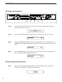
7. Operating the Replifex
Selecting a preset
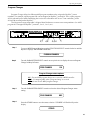
1
Step 1
Turn the PRESET control to the desired preset you wish to recall. The selected preset will be
recalled automatically.
29 PRESET TITLE
35
Operating the Replifex™
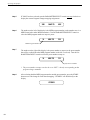
Changing preset parameters
4
Step 1
3
5
2
1
Turn the FUNCTION SELECT control to select the function heading which contains the
parameter(s) you wish to change.
SSSS REVERB SSSS
Step 2
Turn the PARAMETER SELECT control to the specific parameter you wish to change.
REV DECAY
Step 3
Turn the PARAMETER ADJUST control to alter the parameter value. The LED above the
STORE button will light, indicating that the preset has had a parameter altered from its stored
value.
REV DECAY
Step 4
59
32
The COMPARE button may now be pressed to compare the sound of the stored parameter
value to the sound of the altered parameter value.
REV DECAY
59
Storing changed preset parameters
Step 5
While viewing a function or parameter title, press the STORE button to store the altered
parameter(s). "STORED" will flash briefly on the display.
STORED
36
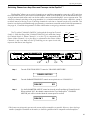
Operating the Replifex™
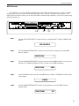
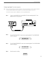
Switching Channels on Amplifiers and Preamps via the Replifex *
The Replifex allows you to switch channels on an amplifier or preamp by connecting a RTS cord from
the "CHANNEL SWITCH" jack on the rear of the Replifex to the "FOOTSWITCH" jack on the remote device(s).
A single stereo-to-dual mono cord can also be used to connect from the Replifex to two separate units. This
allows for channel switching to be programmable (i.e. switched automatically when a Replifex preset is
recalled) instead of having to use a latching footswitch each time a channel needs to be switched. This
function can also be performed through programming a continuous controller to the CHAN SW parameter(s).
See page 41, "Controller Assignments" for more information on assigning continuous controllers.
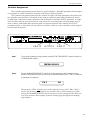
The Tip of the "CHANNEL SWITCH" jack sends the change for Channel
Switch 1, while the Ring of the "CHANNEL SWITCH" jack sends the change
for Channel Switch 2. When Channel 1 is on, the Tip is connected to the
Sleeve. When Channel 2 is on, the Ring is connected to the Sleeve. When
Channels 1 and 2 are both off, the Tip and Ring are an open circuit with
respect to the Sleeve (see diagram).
3,6
Step 1
4,7
2,5
Ch. 1
TIP
RING
Ch. 2
SLEEVE
1
Turn the FUNCTION SELECT control to "CHANNEL SWITCHES".
CHANNEL SWITCHES
Step 2
Turn the PARAMETER SELECT control one step clockwise to "CHAN SW 1".
CHAN SW 1
Step 3
OFF
Use the PARAMETER ADJUST control to select the on/off condition of Channel Switch 1.
When switched "ON", the channel connected to the Tip of the Replifex™ CHANNEL
SWITCH jack will be switched when the current preset is recalled.
CHAN SW 1
ON
* This feature was designed to operate with as many different amplifiers as possible. However, due to the large
number of amplifiers available on the market, it cannot be guaranteed to be compatible with all amplifiers.
37
Operating the Replifex™
Step 4
Press the STORE button to save the condition of Channel Switch 1 (if changed). "STORED"
will flash briefly on the display.
STORED
Step 5
Turn the PARAMETER SELECT control one step further clockwise to "CHAN SW 2".
CHAN SW 2
Step 6
Use the PARAMETER ADJUST control to select the on/off condition of Channel Switch 2.
When switched "ON", the channel which is connected to the Ring of the Replifex ™ CHANNEL SWITCH jack will be switched when the current preset is recalled.
CHAN SW 1
Step 7
ON
Press the STORE button to save the condition of Channel Switch 2 (if changed). "STORED"
will flash briefly on the display.
STORED
38
OFF
Operating the Replifex™
Editing a preset title
3
Step 1
5
2,4
1
To begin the Title Edit function, turn the FUNCTION SELECT control clockwise until the
Replifex™ displays "TITLE EDIT".
SS TITLE EDIT SS
Step 2
Turn the PARAMETER SELECT control clockwise to initiate the Title Edit mode. Turning
this control will also select the character location to be edited. A flashing decimal will follow
the character currently selected.
57 P.RESET TITLE
(Flashing Decimal)
Step 3
Use the PARAMETER ADJUST control to select the desired character for the current position (flashing decimal).
57 M.RESET TITLE
Step 4
To edit the character in the next position, turn the PARAMETER SELECT control one step
clockwise. The flashing decimal will move to the next character.
57 MR.ESET TITLE
(Flashing decimal)
39
Operating the Replifex™
Step 5
After all the characters have been edited as needed, press the STORE button to save the new
title memory. The Replifex™ will flash "STORED" briefly.
STORED
Note:
The STORE button must be pressed to save the new title. Exiting the Title Edit
function before pressing the STORE button will erase any editing that was done
in Title Edit.
Also, after flashing "STORED", the Replifex™ will remain in the Title Edit mode.
You may either (a) turn the PRESET control to display and edit other preset titles
without having to exit and re-enter Title Edit, or (b) turn the FUNCTION SELECT control to exit the Title Edit mode.
40
Operating the Replifex™
Controller Assignments
The Controller Assignment function allows for specific Replifex adjustable parameters to be mapped
(or assigned)* to a MIDI controller for real-time control by an expression pedal.
The Controller Assignment option also lets you store an upper and lower parameter value limit which
the controller cannot exceed. For example, when using an expression pedal with a Rocktron All Access
or MIDI Mate footswitch to send continuous control changes to control the "PITCH" parameter, an upper
limit of +300 can be set and a lower limit of -200 can be set - even though the actual parameter range is
from +1200 to -2400. When the expression pedal is at its heel position in this example, the "PITCH"
parameter will be at -200, while at its toe position it will be at +300. Up to ten controllers can be assigned
for each individual preset.
3,6,9,12
Step 1
4,7,10,13
2,5,8,11
1
To access the Controller Assign function, turn the FUNCTION SELECT control clockwise to
"CONTROLLER ASSIG".
CONTROLLER ASSIG
Step 2
Turn the PARAMETER SELECT control for the first parameter of the Controller Assign
function. This parameter allows you to select a controller number for the "CTR A" (Controller
A) parameter to respond to.
CTR A
XXX
This parameter (CTR A only) also gives you the option of selecting "ADJ". When "ADJ" is
selected, the parameter assigned to the first controller (PA-A) can be instantly accessed by
turning the PARAMETER ADJUST control when the preset title is displayed. This allows you
to access a parameter that you adjust frequently without paging through function headings
and parameters.
41
Operating the Replifex™
Step 3
Use the PARAMETER ADJUST control to select the controller number to be assigned to the
PA-A parameter. Any number from 0 to 120 may be selected, as well as OFF (will not
respond to MIDI control changes). Match the number selected for this parameter with the
controller number on the MIDI transmitter.
CTR A
Step 4
7
After selecting the desired controller number, press the STORE button to save the number for
the "CTR A" parameter. "STORED" will flash briefly on the display.
STORED
Step 5
Turn the PARAMETER SELECT control one step clockwise to display the parameter that is
currently mapped to the "CTR A" control number.
PA-A
Step 6
Turn the PARAMETER ADJUST control to scroll through the available parameters for the
current configuration.
PA-A
Step 7
BYPASS
REVERB LVL
After selecting the parameter that you which to assign to a controller, press the STORE button
to save it. The Replifex™ will flash "STORED" briefly.
STORED
42
Operating the Replifex™
Note:
Step 8
The Replifex™ allows you to select an upper and lower value limit which the
parameter cannot exceed. For example, if a parameter has a value range from -∞
to 0dB, yet you would like the range of the parameter to vary from only -12dB to
-2dB, you may set a lower limit of -12 and an upper limit of -2 via the Upper and
Lower Limit parameters. When a parameter is stored in the Controller Assign
function (Step 7), the maximum parameter value is automatically stored as the
upper limit, while the minimum value is stored as the lower limit.
Turn the PARAMETER SELECT control one step clockwise to display the Upper Limit
parameter (for PA-A).
ULIM A
Step 9
XXX
Use the PARAMETER ADJUST control to choose the highest value that the parameter is not
to exceed through MIDI control changes.
ULIM A
Step 10
-2
After selecting a value for the upper limit, press the STORE button to save it. "STORED" will
flash briefly on the display.
STORED
Step 11
Turn the PARAMETER SELECT control one step clockwise to access the Lower Limit
parameter (for PA-A).
LLIM A
-∞
43
Operating the Replifex™
Step 12
Use the PARAMETER ADJUST control to select the lowest value which the parameter is not
to fall below through MIDI control changes.
LLIM A
Step 13
-12
After selecting a value for the lower limit, press the STORE button to save it. "STORED" will
flash briefly on the display.
STORED
Selecting a lower limit value that is greater than the upper limit value will invert the response
of the controller - i.e. the toe position of the expression controller will provide the minimum
value, while the heel position will provide the maximum value.
Note:
44
Steps 1-13 can be repeated nine times for a total of 10 controllers. To exit
Controller Assign at any time, turn either the PRESET or FUNCTION SELECT
control. Only those changes that have been stored will be saved after exiting the
Controller Assign function.
Operating the Replifex™
Copying Replifex Presets, Titles and Controller Assignments
The Copy function allows you to copy any preset, preset title or controller assignment into any other
preset location instantly.
3
4
5
2
1
Copying presets:
Step 1
Turn the FUNCTION SELECT control to "COPY".
SSSS COPY SSSS
Step 2
Turn the PARAMETER SELECT control one step clockwise to access the "PR> XX to >PR
XX" parameter, as shown below. The number on the left represents the preset to be copied,
while the number on the right represents the preset location to copy to.
PR> 4
TO
Preset to copy
Step 3
TO
>PR 4
Use the PARAMETER ADJUST control to select the location to copy the selected preset into.
PR> 21
Step 5
Preset location to copy to
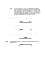
Use the PRESET control to select the desired preset to be copied.
PR> 21
Step 4
>PR 4
TO
>PR 59
Press the STORE button to copy the selected preset into the selected preset location.
"STORED" will flash briefly on the display.
STORED
45
Operating the Replifex™
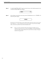
Step 6
After flashing "STORED", the Replifex™ will display "COPY TITLE TOO?". This allows
you to copy the title from the copied preset into the new location as well. To copy the title,
press the STORE button a second time. "STORED" will flash briefly before the Replifex™
displays the new preset number and title.
STORED
Turning the PARAMETER ADJUST control instead of pressing the STORE button allows
you copy the title from the preset being copied to any other location. Once a location has been
selected, press the STORE button to copy the title.
If you do not wish to copy the preset title, turn the PARAMETER SELECT or FUNCTION
SELECT control to exit the preset copy function. The preset has been copied to the new
location, but its title will be the title which was already at the new location.
Copying preset titles:
Step 1
Turn the FUNCTION SELECT control to "COPY".
SSSS COPY SSSS
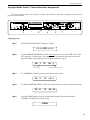
Step 2
Turn the PARAMETER SELECT control two steps clockwise to access the "TI> XX to >TI
XX" parameter, as shown below. The number on the left represents the preset title to be
copied, while the number on the right represents the preset location to copy the title to.
TI> 4
TO
Preset title to copy
Step 3
TO
>TI 4
Use the PARAMETER ADJUST control to select the location to copy the selected preset into.
TI> 21
46
Preset location to copy to
Use the PRESET control to select the desired preset title to be copied.
TI> 21
Step 4
>TI 4
TO
>TI 59
Operating the Replifex™
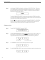
Step 5
Press the STORE button to copy the selected title into the selected preset location.
"STORED" will flash briefly before displaying the preset title at its new location.
STORED
Copying controller assignments:
Step 1
Turn the FUNCTION SELECT control to "COPY".
SSSS COPY SSSS
Step 2
Turn the PARAMETER SELECT control three steps clockwise to access the "CA> XX to
>CA XX" parameter, as shown below. The number on the left represents the preset from
which the controller assignments will be copied, while the number on the right represents the
preset location to copy those controller assignments to.
CA> 4
TO
Preset to copy controller
assignments from
Step 3
TO
>CA 4
Use the PARAMETER ADJUST control to select the location to copy the controller assignments into.
CA> 21
Step 5
Preset location to copy
controller assgnments to
Use the PRESET control to select the desired preset to copy controller assignments from.
CA> 21
Step 4
>CA 4
TO
>CA 59
Press the STORE button to copy the selected preset into the selected preset location.
"STORED" will flash briefly before the Replifex™ displays the preset number and title that
the controller assignments were stored into.
STORED
47
Operating the Replifex™
Tap Delay
The Replifex allows you to change the delay times and/or modulation rates for any given preset while
you are playing two different ways:
1. By tapping the TAP DELAY/RATE button on the front panel of the Replifex, or
2. By tapping a momentary footswitch connected to the rear panel TAP DELAY/
RATE FOOTSWITCH jack.
3. By using a Rocktron All Access in Remote mode with the Replifex and
tapping switch #15.
When any "TIME" parameter within a given preset is set to ½, ¼, TRIPLET, 8TH, 16TH or 32ND NOTE,
tapping the footswitch or the front panel TAP DELAY/RATE button two times will change the current delay
time and/or modulation rate based on the amount of time that passes between taps. The Replifex will detect
the amount of time between any two taps that are less than one second apart (i.e., if more than one second
passes after the first tap, two additional taps - less than one second apart - will be required to change the delay
time again).
After the Replifex detects the length of time between each tap, it then multiplies or divides that time
based on the type of note stored for the TIME parameter(s) of the preset. The resulting delay time can be:
one-eighth of the time between taps (32ND)
one-fourth of the time between taps (16TH)
one-half of the time between taps (8TH)
two-thirds of the time between taps (TRIPLET)
equal to the time between taps (¼), or
two times the amount of time between taps (½)
The maximum delay time the Replifex provides is 1000ms, therefore the Tap Delay feature will automatically default to a lower "TIME" parameter value when the time between taps requires a delay time over
1000ms. For example, if the HALF setting is stored for the TIME 1 parameter and the time between taps is
600ms, a delay time of 1200ms would be required (i.e. 600ms x 2). Because the maximum delay time is
1000ms, the Replifex will default to the next lower multiplier (¼) and provide a delay time equal to the
delay time detected (600ms).
"NONE" can also be selected for the TIME parameter(s) so that they will not respond to taps from the
footswitch or front panel TAP DELAY/RATE button.
48
Note 1:
If delay times for each preset are selected via the Tap Delay feature (instead of
manually setting the parameters), the flashing front panel tap delay rate L.E.D.
will accurately reflect the tapped value that was stored in each preset when it is
recalled. However, the Replifex™ must be displaying either a function heading
or a parameter to store the flashing tap delay rate (i.e., not while displaying a
preset title). If a preset title is displayed when the STORE button is pressed,
only the Power On preset is stored (see page 63).
Note 2:
If a footswitch is connected to the rear panel Tap Delay/Rate FOOTSWITCH
jack when the unit is powered up, the Replifex™ will automatically determine
the type of footswitch connected (i.e. normally open, normally closed, etc.).
However, the footswitch must already be connected when the unit is turned on.
Operating the Replifex™
Program Changes
Program Changes allow for different MIDI program numbers to be assigned to Replifex preset
numbers. For example, MIDI program #58 can be mapped to Replifex preset #34. Then, when program
#58 is selected from a MIDI transmitting device (such as a Rocktron All Access foot controller), preset
#34 will be recalled on the Replifex.
The Program Changes Map table is shipped from Rocktron at a one-to-one correspondance (i.e. MIDI
program #1 is mapped to Replifex preset #1, 2 to 2, 3 to 3, etc.).
3,7
Step 1
4,8
2,5,6
1
To access MIDI Program Mapping, turn the FUNCTION SELECT control clockwise until the
Replifex™ displays "PROGRAM CHANGES".
PROGRAM CHANGES
Step 2
Turn the PARAMETER SELECT control one step clockwise to display the current Program
Change On/Map/Off status.
PROG CHANGES
ON
Program Changes status options
ON - Execute MIDI program changes as received by a MIDI controller
MAP - Use mapping table when a program change is received
OFF - Do not execute MIDI program changes
Step 3
Turn the PARAMETER ADJUST control to select the desired Program Changes status
setting.
PROG CHANGES
Step 4
MAP
Press the STORE button to save the status selection. "STORED" will flash briefly on the
display.
STORED
49
Operating the Replifex™
Step 5
If "MAP" has been selected, turn the PARAMETER SELECT control one step clockwise to
display the current Program Changes mapping assignments.
XXX
Step 6
MAP TO
XXX
The number on the left of the display is the MIDI program number (or the number sent via a
MIDI footswitch or other MIDI transmitter). Turn the PARAMETER SELECT control to
select the MIDI program number to map to a preset.
14
MAP TO
120
MIDI Program Number
Step 7
The number on the right of the display is the preset number to map to (or the preset number
that will be recalled when the MIDI program number on the left is received). Turn the PARAMETER ADJUST control to select the preset number to map to.
14
MAP TO
112
Replifex Preset Number
* The preset number to map to can also be set to "OFF" - thereby not responding to that
program change command.
Step 8
After selecting both the MIDI program number and the preset number, press the STORE
button to save the change for each altered mapping. "STORED" will flash briefly on the
display.
STORED
50
Operating the Replifex™
MIDI Channels
The Replifex can receive MIDI commands from other MIDI transmitting devices, as well as transmit
MIDI program changes to other MIDI-based equipment when a preset is recalled on the Replifex. The
MIDI Channels function allows you to select the MIDI channels that the Replifex will receive and transmit
MIDI information on.
3,6
Step 1
4,7
2,5
1
Turn the FUNCTION SELECT control clockwise until the Replifex™ displays "MIDI CHANNELS".
MIDI CHANNELS
Step 2
Turn the PARAMETER SELECT control one step clockwise to display the current MIDI
Receive channel.
RECEV CHANL
Step 3
Turn the PARAMETER ADJUST control to select the desired MIDI channel. You may select
channels 1-16, OMNI (all channels) or OFF (will not receive MIDI commands).
RECEV CHANL
Step 4
1
OMNI
Press the STORE button to save the new MIDI Receive channel. "STORED" will flash briefly
on the display.
STORED
Step 5
Turn the PARAMETER SELECT control one step further to access the MIDI Transmit
Channel status.
TRANS CHANL
OFF
51
Operating the Replifex™
Step 6
Turn the PARAMETER ADJUST control to select the channel that the Replifex™ will transmit a MIDI program change on. You may select channels 1-16 or OFF (will not transmit a
MIDI program change).
TRANS CHANL
Step 6
1
Press the STORE button to save the new MIDI Transmit channel. "STORED" will flash
briefly on the display.
STORED
After the desired MIDI channels have been selected, turn the FUNCTION SELECT control to
exit the MIDI Channels function.
52
Operating the Replifex™
MIDI Dump/Load
Any or all of the Replifex presets may be dumped to a sequencer or another Replifex via system
exclusive messages. The information exchanged when performing a MIDI Dump consists of parameter
values, title characters and controller assignment information. When dumping a single preset into another
Replifex, the dumped preset may be loaded into any preset location on the receiving Replifex.
To dump a single Replifex™ preset into another Replifex™
Step 1
Connect a standard MIDI cable from the MIDI OUT of the transmitting Replifex™ to the
MIDI IN on the receiving Replifex™.
IMPORTANT: Do not allow a looping connection from the MIDI OUT/THRU of the receiving Replifex™
back to the MIDI IN of the transmitting Replifex™.
Step 2
Step 3
Turn the FUNCTION SELECT controls on both the transmitting and receiving Replifexes
until "MIDI DUMP/LOAD" is displayed on each.
MIDI DUMP/LOAD
MIDI DUMP/LOAD
TRANSMITTING REPLIFEX
RECEIVING REPLIFEX
Turn the PARAMETER SELECT control on each unit one step clockwise to "PR DUMP/
LOAD".
1 PR DUMP/LOAD
TRANSMITTING REPLIFEX
1 PR DUMP/LOAD
RECEIVING REPLIFEX
53
Operating the Replifex™
Step 4
Turn the PRESET control on the transmitting Replifex™ to the preset that is to be dumped into
the receiving Replifex™. As the PRESET control is turned, the preset number will be displayed in the first three characters of the display.
32 PR DUMP/LOAD
TRANSMITTING REPLIFEX
Step 5
Use the PRESET control on the receiving Replifex™ to select the preset location to store the
received preset. (The preset currently stored at the selected location will be lost when the new
preset is received, therefore caution should be used when selecting a preset location.)
122 PR DUMP/LOAD
RECEIVING REPLIFEX
Step 6
To initiate the dump, press the STORE button on the transmitting Replifex™. The transmitting
Replifex™ will display the preset number being dumped and "DUMPED". The receiving
Replifex™ will display the preset location being stored to and "RECEIVING..." while it
receives and stores the preset parameters and title.
32 DUMPED
122 RECEIVING...
TRANSMITTING REPLIFEX
RECEIVING REPLIFEX
After all the information for the dumped preset is stored, the receiving Replifex™ will display
"LOADED". The receiving Replifex™ also recalls the loaded preset at this time so that it may
be verified.
122 LOADED
RECEIVING REPLIFEX
Note: If there is an error in transmission, the unit will display "RECEIVE ERROR". Should
this occur, check connections and try again. If other errors occur, check the Error
Messages chart in the Appendix.
54
Operating the Replifex™
To dump a single Replifex™ preset into a sequencer:
Note:
When performing data dumps to and from the Replifex™, always perform the dump in real time sequence mode. This
will ensure that data loaded back into the Replifex™ is not sent faster than the Replifex™ can receive it.
Also, make sure that the sequencer's MIDI filter is set to accept SYSX information.
Step 1
Connect a standard MIDI cable from the MIDI OUT of the transmitting Replifex™ to the
MIDI IN on the receiving sequencer.
Step 2
Turn the FUNCTION SELECT controls on the transmitting Replifex™ until "MIDI DUMP/
LOAD" is displayed.
MIDI DUMP/LOAD
TRANSMITTING REPLIFEX
Step 3
Turn the PARAMETER SELECT control on the transmitting Replifex™ until "BULK DUMP/
LOAD" is displayed.
BULK DUMP/LOAD
TRANSMITTING REPLIFEX
Step 4
Start the sequencer recording.
RECORD
55
Operating the Replifex™
Step 5
Press the STORE button on the Replifex™ to initiate the data dump. As the Replifex™ performs the dump, it will display "XXX DUMPED" - where "XXX" = the number of the data
string currently transmitting (i.e. strings 1-254 are presets, titles, controller information and 2tap delay information; string 255 contains program mapping information; and string 256
contains miscellaneous information. Contact Rocktron Corporation for information on how to
receive a detailed MIDI spec).
XXX DUMPED
TRANSMITTING REPLIFEX
Step 6
After the Replifex™ displays "TRANS COMPLETE", stop the sequencer. The sequencer should
have recorded all of the data that was dumped from the Replifex™. Keep this data stored on a disk
in a safe place. Turn the PARAMETER SELECT control to continue.
STOP
56
Operating the Replifex™
To reload user data from a sequencer:
Step 1
Connect a standard MIDI cable from the MIDI OUT of the transmitting sequencer to the
MIDI IN on the receiving Replifex™.
IMPORTANT: Do not allow a looping connection from the MIDI OUT/THRU of the receiving Replifex™
back to the MIDI IN of the transmitting sequencer.
Step 2
Turn the FUNCTION SELECT controls on both the receiving Replifex™ until "MIDI DUMP/
LOAD" is displayed.
MIDI DUMP/LOAD
RECEIVING REPLIFEX
Step 3
Turn the PARAMETER SELECT controls on the receiving Replifex™ until "BULK DUMP/
LOAD" is displayed.
MIDI DUMP/LOAD
RECEIVING REPLIFEX
57
Operating the Replifex™
Step 4
Play back the data stored on the sequencer. The Replifex™ will display the data strings as it is
storing them. Each data string will appear with the word "LOADED". After all the user data
has been loaded, the Replifex™ will display "LOAD COMPLETE". Do not play back the data
from the sequencer faster than it was loaded, as errors may occur (errors may also occur if
any knob is turned or any button is pressed before the message "LOAD COMPLETE"
appears).
LOAD COMPLETE
RECEIVING REPLIFEX
If errors occur during transmission, the unit will display "RECEIVE ERROR" for transmission
errors and "XMEM ERROR" for internal hardware errors. Errors occurring in transmission
does not indicate that all of the received data is corrupted. Only the transmission string where
the error occurred is corrupted.
Y When receiving a Bulk Load, it is important that the data loaded to the Replifex™
is not transmitted faster than it was originally dumped from the Replifex™. If
information is sent too fast to the Replifex™, an error will occur.
When dumping information from a data storage device, such as an Alesis Data
Disk, it is necessary to perform the dump in sequence mode rather than sysx
mode. Sequence mode will dump the information back to the Replifex™ at the
same rate as it was received from the Replifex™. The Replifex™ can receive a
data dump at about 65Hz (or about 1 byte every 15 milliseconds).
58
Operating the Replifex™
Factory Restore
The Factory Restore function allows you to restore altered Replifex presets to their original condition
as shipped from the factory. Either the entire Replifex memory can be restored, a single preset can be
restored to any preset location, or the controller information alone can be restored.
Restoring a single factory preset:
3
Step 1
4
5
2
1
Turn the FUNCTION SELECT control clockwise to "FACTORY RESTORE".
FACTORY RESTORE
Step 2
Turn the PARAMETER SELECT control one step clockwise to "RESTR 1 TO 1". The
number on the left is the original factory preset number to be restored. The number on the
right is the preset location that the preset will be stored into.
RESTR
1
TO
1
Factory preset to be restored
Step 3
Turn the PRESET control to select the factory preset to be restored.
RESTR
Step 4
Preset location to store into
98
TO
1
Turn the PARAMETER ADJUST control to select the preset location to store the restored
preset into.
RESTR
98
TO
22
59
Operating the Replifex™
!! CAUTION !!
Pressing the STORE button at this time will overwrite
the current preset with the displayed factory preset.
Step 5
Press the STORE button to begin restoring the selected preset into the selected location. After
the process is completed, the display should read "ERRORS 0". This represents the number
of bytes that the Replifex™ found did not initialize properly. Any number of errors other than
"0" means that the Replifex™ may not have initialized properly and the process should be
repeated.
ERRORS
0
The Replifex™ will remain in this condition until the FUNCTION SELECT control is
turned to exit the Factory Restore function. The preset currently recalled will be the preset
most recently restored into the current location.
60
Operating the Replifex™
Restoring the Replifex™ memory (all presets):
!! CAUTION !!
This procedure will permanently erase all user presets (1-128) and replace them
with the original factory presets. If you have altered and stored presets which
you do not want to erase, do not perform the following procedure.
3
Step 1
4
2
1
Turn the FUNCTION SELECT control clockwise to "FACTORY RESTORE".
FACTORY RESTORE
Step 2
Turn the PARAMETER SELECT control two steps clockwise to "ALL RESTORE 0".
ALL RESTORE
Step 3
0
A specific code number must be entered to restore the Replifex™ memory. Use the PARAMETER ADJUST control to enter the number "243".
ALL RESTORE
243
!! WARNING !!
Pressing the STORE button at this time will permanently erase all
user presets and replace them with the original factory presets. If
you have altered and stored presets which you do not want to erase,
turn the FUNCTION SELECT control to exit this function.
61
Operating the Replifex™
Step 4
Press the STORE button at this time to initiate the All Restore procedure and erase all current
Replifex™ presets, replacing them with the original factory presets. The Replifex™ will display
"INITIALIZING" as the Replifex™ memory is restored.
INITIALIZING
After the All Restore process is completed, the display should read "ERRORS 0". This is the
number of bytes that the Replifex™ found that did not initialize properly. Any number of
errors other than "0" means that the Replifex™ may not have initialized properly and the
process should be repeated.
ERRORS
0
The Replifex™ will remain in this condition until the FUNCTION SELECT control is
turned to exit the Factory Restore function. The preset currently recalled will be the preset
most recently restored into the current location.
Restoring the Replifex™ controller assignments:
The controller assignments for the Replifex can also be reinitialized without
affecting presets and other stored information. Reinitialization of the controller assignments is necessary when setting up the Replifex to operate in remote mode with a
Rocktron All Access footswitch.
To reinitialize only the controller assignments, enter a code number of "244" at
Step 3 on the preceding page (instead of the "243" shown).
62
Operating the Replifex™
Selecting a Power On Preset
The Replifex allows you to store a Power On preset which will always be recalled when the unit is
turned on.
1
Step 1
2
Turn the PRESET control to the preset number you wish to be recalled each time the unit is
turned on.
34 PRESET TITLE
Step 2
Press the STORE button while viewing the preset number and title to save it as the Power On
preset.
PWR ON PR STORED
63
Operating the Replifex™
Using the Replifex with a Rocktron All Access in REMOTE mode
A Rocktron All Access MIDI footswitch can be configured as a dedicated remote control for the
Replifex - allowing direct access to specific Replifex features and parameters from the footswitch at any
time.
Step 1
To use an All Access™ footswitch as a dedicated remote, connect the MIDI OUT of the All
Access™ to the REMOTE jack of the Replifex™ using a 7-pin MIDI cable, as shown below.
To set up the Replifex™ for remote operation, do the following:
Step 2
Reinitialize the controller assignments as shown on page 62 under the heading "Restoring the
Replifex™ Controller Assignments". This will match up the Replifex's controller assignments
to the All Access™. A code of "244" must be entered to initialize only the controller
information.
ALL RESTORE
64
244
Operating the Replifex™
Step 3
Turn the FUNCTION SELECT control clockwise to "REMOTE CONTROL".
REMOTE CONTROL
Step 4
Turn the PARAMETER SELECT control one step clockwise to display "REMOTE".
REMOTE
Step 5
OFF
Turn the PARAMETER ADJUST control to select "ON".
REMOTE
Step 6
ON
Press the STORE button to save the Remote on/off status. "STORED" will flash briefly.
REMOTE
Step 7
ON
If the Replifex™ titles are to be displayed on the All Access™, turn the PARAMETER
SELECT control to "TITLE XFER".
TITLE XFER
Step 8
Turn the PARAMETER ADJUST control to "ON" to enable title transfers from the Replifex™
to the All Access™ display.
TITLE XFER
Step 9
OFF
ON
Press the STORE button to save the Title Transfer on/off status. "STORED" will flash briefly.
STORED
65
Operating the Replifex™
To set up the All Access™ for remote operation, perform these steps from the All Access™ SETUP program:
(See the All Access™ user's manual for detailed information on editing the All Access™)
Step 8
Set the Operating Mode to "REMOTE".
Step 9
Set the Bank Size to "5".
Step 10
Reinitialize only the controller information for the instant access switches and pedals using
the All Access™ Controller Restore code number "231".
Step 11
If the preset titles from the Replifex™ are to be displayed on the All Access™ automatically,
set the Remote Title Number to match the Unit ID Number parameter on the Replifex™.
When operating the All Access in Remote mode with a Replifex, switches 1-5 act as normal
preset switches, while other switches are automatically configured to perform special functions, as described below.
"Classic" Configuration
66
"Rotary" Configuration
Switch 6
Switches the EQ effect in or out.
Switch 6
Switches the EQ effect in or out.
Switch 7
Switches the Flanger effect in or out.
Switch 7
No function
Switch 8
Switches the Tremolo effect in or out.
Switch 8
Selects Slow or Fast Rotary speed.
Switch 9
Switches the Pitch Shift effect in or out.
Switch 9
Sends the change for Channel Switch 1.
Switch 10
Switche the Phaser effects in or out.
Switch 10
Sends the change for Channel Switch 2.
Switch 11
Allows you to bypass the Replifex™.
Switch 11
Allows you to bypass the Replifex™.
Switch 12
Switches the Reverb effect in or out.
Switch 12
Switches the Reverb effect in or out.
Switch 13
Switches the Chorus effect in or out.
Switch 13
Switches the Rotary Speaker effect in or out.
Switch 14
Switches the Delay effect in or out.
Switch 14
Switches the Delay effect in or out.
Switch 15
Instant Tap Delay access.
Switch 15
Instant Tap Delay access.
Pedal 1
Controls the Volume parameter.
Pedal 1
Controls the Slow Rotary speed.
Pedal 2
Controls the Volume parameter.
Operating the Replifex™
Remote mode functions in "Classic" configuration
Upon proper setup and connection of the Replifex ™ and All Access™ units, the All Access™ will provide the
functions shown above when a "Classic" configuration preset is recalled.
67
Operating the Replifex™
Remote mode functions in "Rotary" configuration
Upon proper setup and connection of the Replifex ™ and All Access™ units, the All Access™ will provide the
functions shown above when a "Rotary" configuration preset is recalled.
68
Operating the Replifex™
Selecting a Configuration
The Replifex allows you to select which configuration - Classic or Rotary - is active for the current
preset.
3
Step 1
4
2
1
Turn the FUNCTION SELECT control fully clockwise to "CONFIG SELECT".
CONFIG SELECT
Step 2
Turn the PARAMETER SELECT control to access the "XXXXXXX SELECTED"
parameter.
CLASSIC SELECTED
Step 3
Turn the PARAMETER ADJUST control to select the desired configuration.
ROTARY SELECTED
Step 4
Press the STORE button to save the selected configuration. "STORED" will flash briefly on
the Replifex™ display.
STORED
69
Error Messages
8. Appendix
ERROR MESSAGES
Message
Possible Reason
Corrective Action
MEMORY ERROR
CODE BYTE IS NOT CORRECT IN
EEPROM MEMORY.
MAKE SURE EEPROM IS TIGHT IN
SOCKET.
MAKE SURE WITHIN CORRECT
OPERATING TEMPERATURE.
DUMP ERROR
RECEIVE ERROR
MIDI INFORMATION IS BEING
RECEIVED AT THE MIDI IN AT
THE SAME INFORMATION IS
BEING DUMPED.
DISCONNECT MIDI CORD AT MIDI
IN OF TRANSMlTTING REPLIFEX.
MIDI SYSTEM EXCLUSIVE
INFORMATION WAS NOT
RECEIVED CORRECTLY.
BULK LOAD WAS TRANSMITTED
TOO FAST.
CHECK SUM BYTE WAS NOT
CORRECT.
DATA STRINGS NOT CORRECT
LENGTH.
DATA STRINGS OUT OF ORDER.
XMEM ERROR
EEPROM MEMORY IS NOT BEING
STORED TO CORRECTLY.
MAKE SURE EEPROM IS TIGHT IN
THE SOCKET.
MAKE SURE WITHIN THE CORRECT
OPERATING TEMPERATURE.
LOAD ERRORS
70
MIDI SYSTEM EXCLUSIVE
INFORMATION WAS NOT
RECEIVED CORRECTLY OR
STORED CORRECTLY.
CHECK RECEIVE ERROR AND
XMEM ERROR.
MIDI Implementation
MIDI IMPLEMENTATION
Replifex™
Date: March 1, 1994
Version: 1.0
FUNCTION
TRANSMITTED
RECOGNIZED
REMARKS
BASIC
CHANNEL
DEFAULT
CHANGED
1-16
1-16
1-16
1-16
May be saved in
non-volatile memory
MODE
DEFAULT
MESSAGES
ALTERED
X
X
X
X
X
X
TRUE VOICE
X
X
VELOCITY
NOTE ON
NOTE OFF
X
X
X
X
AFTER
TOUCH
KEY'S
CHANNEL
X
X
X
X
PITCH BEND
X
X
CONTROL
CHANGE**
X
O
O
O
O
O
NOTE
NUMBER
PROGRAM
CHANGE*
TRUE NUMBER
SYSTEM
EXCLUSIVE
SYSTEM
COMMON
SONG POSITION
SONG SELECT
TRUE REQUEST
X
X
X
X
X
X
SYSTEM
REAL TIME
CLOCK
COMMANDS
X
X
X
X
AUXILIARY
MESSAGES
LOCAL ON/OFF
ALL NOTES OFF
ACTIVE SENSING
SYSTEM RESET
X
X
X
X
X
X
X
X
For Bulk Dump/Load
and Preset Dump/
Load
O=YES
X=NO
*
Actual MIDI program value sent is 0-127, corresponding to presets 1-128. Optional
implementation of program mapping also available.
** The control number may be from 0-120, or OFF. An upper and lower range may also
be specified for most parameters.
71
Technical Data
TECHNICAL DATA
MEASUREMENT
CONDITIONS
Maximum Input:
+20dBu
Input Level pot minimum
Maximum Output:
+20dBu
Output Level pot maximum
Nominal Input Range:
(16dB Headroom)
+4dBu to
-21dBu
Input Level pot minimum
Input Level pot maximum
Input Impedance:
470K ohms
Output Impedance:
120 ohms
Dynamic Range:
104dB (HUSH IN)
94dB (HUSH OUT)
Peak Signal/A Weighted Noise Floor,
Direct Level = +6dB, Direct Post HUSH,
Effects Level = -∞
THD+N
.009%
1kHz, -5dB input level
22Hz to 22kHz bandwidth
Direct Level = +6dB, Direct Post HUSH,
Effects Level = -∞
Dry Frequency Response
(10Hz to 100kHz) +.25, -2dB
(10Hz to 30kHz) ±.25dB
Wet Frequency Response
(20Hz - 14.5kHz) +5, -3dB
Rocktron Corporation
2870 Technology Drive
Rochester, MI 48309
Customer Service: (810) 853-3055
Fax Number:
(810) 853-5937
72
Factory Presets
REPLIFEX FACTORY PRESETS
1
2
3
4
5
6
7
8
9
10
11
12
13
14
15
16
17
18
19
20
21
22
23
24
25
26
27
28
29
30
31
32
33
34
35
36
37
38
39
40
41
42
43
44
45
REAL ROTARY
ETHERIAN
RETRO PAN
CONE TONE
TELSTAR
PONG/PLEX
BIG PLATE
DYNA/VERB
DIMENSION C
BOX FLANGE
PHASE 100
SMALL STONE
BLUE CHORUS
TREMOLUX
EARTH TREM
ECHO SPILL
BLANKETAIL
DYNA COMP
CLEAN VERB
l\a wash
vaiable
add 9
chorus*phase
sweet spot
flangecho
phasecho
t-phasecho
psychomania
stereo echo
slap echo
happy third
oc-2
seasick
aggravated
date w<elvis
digi dale
maximum bo
badge
itchykoopark
james bond
duane eddy
orangesqueeze
hellbender
70's multi
swamp thing
46
47
48
49
50
51
52
53
54
55
56
57
58
59
60
61
62
63
64
65
66
67
68
69
70
71
72
73
74
75
76
77
78
79
80
81
82
83
84
85
86
87
88
89
90
tremopan
third stone
matchstikmen
small plate
let it rain
sock hop
crmson+clovr
b-flick
dudlydoright
ska spank
'70's miles
pulp fission
everly rhthm
chess studio
big plate
cliff's galop
too stoned
verb
dly/rvb
crs/dly/rvb
crs/rvb
bo did
machine
12 string
may
plex
plex slap
spring verb
FLUID
KEEP ALIVE
SUPER CRS
SOLO BACKING
SMALL ROOM
ROTATING IT
CLEAN
FIFTH NOTE
RUMBLE
HUSH 2
SILENCER
GATE
HUSH COMPRES
EQ/HUSH
EQ/GATE
STEREO DELAY
RUBBER ROOM
91
92
93
94
95
96
97
98
99
100
101
102
103
104
105
106
107
108
109
110
111
112
113
114
115
116
117
118
119
120
121
122
123
124
125
126
127
128
DELAY THIS
DELAY FLANGE
PRE DELAY 1
PRE DELAY 2
PRE DELAY 3
EFFECT\DIRECT
DEATH SCOOP
MEGA PHONE
1 DOWN
ROTARY DRY S
ROTARY DRY
ROTARY SM RM
ROTARY LG RM
ROTOR CANYON
ROTO 145
ROTARY WIDE
COLD SHOT
HESITATE
ROTOR * DRY 1
ROTOR * DRY 2
Q FACTOR
BADGE 2
NOT EASY
GOODTIMES
ROTOGROWL
ROTO ARENA
ON THE ROAD
WARM
FLUID 2
COMP ROTARY
NERVOUS
FLUID 3
ROTARY SLAP
DRY/FAST VIB
ROTO W/HUSH
ROTO/SPRINGVRB
ROTO/PLEX
test
73