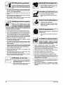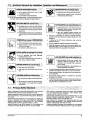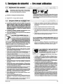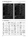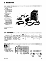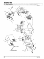
1
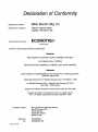
OM107 439F
April
Eff. w/Se rial Number KH374223
Miller
The Power ofBlue.
Processes
~
~
Gas
Tungsten
(TIG) Welding
Arc
Shielded Metal Arc
(Stick) Welding
Description
Arc
Welding
Power Source
CE
0
-
lull
I
Visit
our
website at
www.millerweids.com
! MANUAL
1997
~
~
~
~
-
S~n~
~
%~<
~
~4W~$~
From Miller ito You
~k~%tt\~
\\~
~
flfl~~
~
~
*~
~
%%%
~
fl~&~,
?*~nfttt
S$~J
~*~
~
Thank you and
can
have time to do it any other way.
you dont
Thats
~~
Miller
help
Manual is
products.
you protect
designed
to
help
f~
A~
yourself against potential
on
r4~~j~k~
will
the worksite. Weve
operation quick
k~*t~
REGISTERED
QUALITY SYSTEM
~
Miller Is the first welding
equipment manufacturer in
the U.S.A. to be registered
to the iSO 9001 Quaiity
System Standard.
~N *~
4H~N~~
-~-r
and easy.
~ \~?
~~
:~
~
~
::11:~::.~
~
:::~
:
::1;~:
~
:
~
\~
N
~twc ~
N
~1pn~ -~aa~
t~:~ :~
~S~net ~
~
_
-~
N
~ea
~flWWWY~-*.
I
Miller Electric manufactures
of welders and
welding
For information
on
a
~Sb~
full line
s~
equipment.
quality Miller
your local Miller distributor
to receive the latest full line catalog or
products,
~a-~
I
related
other
contact
sheets. To locate your
distributor call 1-800-4-A-Miller.
individual
catalog
nearest
:~:~:::1~~
~
m$z~sa~ ta~
on
~
~
Troubleshooting section that will help you
figure out what the problem is. The parts list
will then help you to decide which exact part
you may need to fix the problem. Warranty and
service information for your particular model
are also provided.
count
~
~
~
~SSI4~!~n
can
N
%
years of reliable
service with proper maintenance. And if for
some reason the unit needs repair, theres a
With Miller you
______________
~
a~
p!!t~!r~
~
litlilil t
~
~%N~
~
made installation and
~
j~:: ~
~t~Tra_N~
Safety precautions. They
hazards
t7t
i~*
you get the most out of your
Please take time to read the
N
N~
~aa
the
This Owners
~k
-
people that build and sell Miller producl:s continue the
tradition. Theyre just as committed to providing equipment and service
that meets the high standards of quality and value established in 1929.
Today,
a
~
~J
when Niels Miller first started
building arc
welders in 1929, he made sure his products offered
long-lasting value and superior quality. Like you, his
customers couldnt afford anything less. Miller products
had to be more than the best they could be. They had to
be the best you could buy.
why
~
~
you
congratulations on choosing Miller. Now
get the job done and get it done right. We know
N~ ~
-
~
-~
it/pr
)NN
Description
Features
AC
output for superior aluminum welding
DC output for mild and stainless steel
Four-position polarity and range selector
switch offers two AC current ranges, DC
electrode ()forTlG, and DC electrode (+)for
Stick
Patented technologyand Millers vast experience in
powersourcedesign cometogetherin atrulyafford
package. The Econotigfi is
a full-featured machine that brings you capabilities
which were previously available only with heavy
duty industrial TIG equipment. You get big machine
performance from a sleek, compact package.
able and effective TIG
The
tive
Patented, built-in
TIG
Process switch
for TIG or Stick
easy to use. Its an excellent choicefori,ovice users
and hobbyists, but dont
underestimate this
arc
assist stabilizer for AC
arc
assist starter for DC TIG
aluminum
Patented, built-in
Econotigs unique design and Millers innova
engineering make a system that is incredibly
automatically
sets machine
Unique flow-through shielding gas TIG torch
connection allows removal of torch without
machines power. It has the strength arid stamina to
handle a wide variety of light indus~riaI welding
tasks. Yet it operates off single-phase power.
Econotig is a complete AC/DC, TIG and Stick
welding package. There are no hidden costs or ex
tras to buy. All you need is a bottle of shielding gas
and some Stick electrodes and youre ready to start
welding. Its ideal for farmers, ranchers, hobbyists
and moonlighters anyone who requiresthe versa
tility to handle Stick work, plus the finesse available
only from the TIG process.
on
tools
Preset automatic postflow timer protects
tungsten tip, workpiece and torch
The
Automatic
Call
tive welder.
shutdown
Processes
Gas
Tungsten
(TIG) Welding
IntheTIG mode, the
Econotigofferssuperiorperfor
mance: 18 gaugeto3/1 6in (1 .2to4.8 rnm)steel and
stainless steel; 14 gauge to 3/16 in (1.3 to 4.8 mm)
aluminum (see Section 5.4). For thicker metals,
take advantage of the Stick mode using 3/32 and 1/8
in (2.4and 3.2 mm) electrodes. No matterwhatlevel
of skill and experience you have, the Econotig will
help you be a more effective, versatile and produc
high temperature
Arc
Shielded Metal Arc
~
(Stick) Welding
The
following terms are
throughout this manual:
used
interchangeably
TIG
GTAW
Stick
SMAW
=
=
1-800-4-A-MILLER
for your local
Miller distributor.
Your distributor
gives
you
Service
You always get the fast,
reliable
response
you
need. Most replacement
parts can be inyourhands
in 24 hours.
Support
Need fast
answers
to the
Table of Contents
Section
1.
Safety
Page
Precautions
1
2. Definitions
9
tough welding questions?
Contact your distributor.
The
expertise of the
distributor and Miller is
there to help you, every
step of the way.
3. Introduction
11
4. Installation
12
5.
.~
Operation
5
Miller offers a Technical Manual
which provides more detailed
service and parts information for
your unit. To obtain a Technical
Manual,
6. Maintenance and
Troubleshooting
18
contact your local distrib
utor. Your distributor
supply you
7. Electrical
8.
Diagram
High Frequency
19
20
with
can
Welding
also
Process
Manuals such as SMAW,
GMAW, and GMAW-P
For practical information
GTAW,
on
ing,
9. Parts List
22
www.mlflerwelds.com
Options and
Warranty
Accessories
weld
process applications, and Miller
products, visit our website at
Declaration of
Manufacturers
Name:
Miller Electric
Manufacturers
Address:
1635 W.
Declares that the
Conformity
Mfg.
Co.
Spencer Street
Appleton, WI 54914 USA
E CO N OT I (~ ~
product:
(product name)
conforms to the
following
Directives and Standards:
Directives
Electromagnetic Compatibility
Low
Voltage
Directives: 89/336EEC, 92/31/EEC
Directive: 73/23/EEC
Machinery Directives: 89/392/EEC, 91/368/EEC, 93/C 1 33/04,
93/68/EEC
Standards
Electromagnetic Compatibility (EMC)
Product standard for
EN5O 199:
Safety Requirements
Arc
forArc
August
arc
welding equipment:
1995
Welding Equipment part
1: EN 60974-1: 1990
Welding Equipment Part 1: Welding Power Sources:
(Apr11 1995 Draft revision)
Degrees
of Protection
provided by
Enclosures
(IP code):
IEC 974-1
IEC 529:1989
Insulation coordination for equipment within low-voltage systems:
Part 1: Principles, requirements and tests: IEC 664-1:1992
European Contact:
Mr.
Luigi Vacchini, Managing
Europe S.P.A.
MILLER
Via Privata lseo
20098 San Giuliano
Milanese, Italy
Telephone:
Fax:
dec_con 1 7/95
39(02)98290-1
39(02)98281-552
Director
1.
Safety Precautions
11
Read Before Using
Symbol Usage
~
~
......~......
.~
.
~.
~
..~
..~
:::~:.~
OM-167 439F
Marks
This group of symbols means Waming! Watch Out! possible
ELECTRIC SHOCK, MOVING PARTS, and HOT PARTS hazards.
Consult symbols and related instructions below for necessary
actions to avoid the hazards.
special safety message.
a
~ Means Note~
not
safety related.
~E. ~
A
The
symbols
: :.:.: .:.
::..
are used throughout this manual
identify possible hazards. When you
shown below
to call attention to and
symbol, watch out, and follow the related instructions
safety information given below is
only a summary of the more complete safety information
found in the Safety Standards listed in Section 1.4. Read and
follow all Safety Standards.
see
the
Only qualified persons
repair
A
should
install, operate, maintain, and
this unit.
:
Do not
drape
If earth
grounding
with
a
to avoid the hazard. The
A
Date, safety_som 4/97
Means Warning! Watch Out! There are possible
hazards with this procedure! The possible hazards are
shown in the adjoining symbols.
a
A
-
cables
your body.
workpiece is required, ground it directly
do not use work clamp or work cable.
over
of the
separate cable
Do not touch electrode if you are in contact with the work,
or another electrode from a different machine.
Use
ground,
only well-maintained equipment. Repair or replace damaged
at once. Maintain unit according to manual.
parts
Wear
During operation, keep everybody, especially children, away.
a safety harness if working above floor level.
Keep all panels and covers securely in place.
Clamp work cable with good
or
r~:SHOQKcawkIIL1..2~
~
.
worktable
Insulate work
.
~,
as near
metal-to-metal contact to
the weld
as
workpiece
practical.
clamp when not connected to workpiece to prevent
object.
contact with any metal
live electrical parts can cause fatal
shocks or severe burns. The electrode and work
circuit is electrically live whenever the output is on.
The input power circuit and machine internal
circuits are also live when power is on. In semiautomatic or
automatic wire welding, the wire, wire reel, drive roll housing, and all
metal parts touching the welding wire are electrically live. Incorrectly
installed or improperly grounded equipment is a hazard.
Touching
Do not touch live electrical
SIGNIFICANT DC VOLTAGE exists after removal of
input power on inverters.
Turn Off inverter, disconnect input power, and discharge input
capacitors according to instructions in Maintenance Section
before
touching any parts.
parts.
~
-
Wear
hole-free
dry,
Insulate
insulating gloves
and
body protection.
yourself from work and ground using dry insulating mats
big enough to prevent any physical contact with the
ground.
or covers
work
or
Do not
use
there is
a
Use AC
If AC
AC output in damp areas, if movement is confined,
of falling.
or
output
output
is
required,
remote
If
output control if present
fumes and gases. Breathing
these fumes and gases can be hazardous to your
health.
on
inside,
remove
out of the fumes. Do not breathe the fumes.
ventilate the
welding
area
and/or
use
exhaust at the
If ventilation is poor,
input power or stop engine before installing or
servicing this equipment. Lockout/tagout input power according
to OSHA 29 CFR 1910.147 (see Safety Standards).
Read
manufacturers instructions for metals, consumables,
cleaners, and degreasers.
Properly install and ground this equipment according
Work in
Disconnect
to its
Manual and national, state, and local codes.
Always verify the supply ground check and be sure that input
power cord ground wire is properly connected to ground terminal
in disconnect box or that cord plug is connected to a properly
grounded receptacle outlet.
When
making input connections, attach proper grounding
conductor first
double-check connections.
Frequently inspect input power cord for damage or bare wiring
replace cord immediately if damaged bare wiring can kill.
Turn off all
equipment
Do not
worn,
use
OM-167 439
when not in
use.
damaged, undersized,
or
poorly spliced cables.
the
arc
to
fumes and gases.
unit.
Owners
1
be hazardous
Welding produces
=9,
Keep your head
required for the welding process.
use
can
if
danger
ONLY if
FUMES AND GASES
Material
use an
Safety
approved air-supplied respirator.
Data
Sheets
(MSDS5)
and
the
coatings,
a confined space only if it is well ventilated, or while
wearing an air-supplied respirator. Always have a trained watchperson nearby. Welding fumes and gases can displace air and
lower the oxygen level causing injury or death. Be sure the
breathing air is safe.
Do not weld in locations near degreasing, cleaning, or spraying
operations. The heat and rays of the arc can react with vapors to
form highly toxic and irritating gases.
Do not weld
cadmium
on coated metals, such as galvanized, lead, or
plated steel, unless the coating is removed from the
weld area, the
area
is well ventilated, and if necessary, while
wearing an air-supplied respirator. The coatings and any metals
containing these elements can give off toxic fumes if welded.
1
can
bum eyes and skin
Shutoff
shielding gas supply when not in
Always ventilate confined spaces or
approved air-supplied respirator.
Arc rays from the welding process produce intense
visible and invisible (ultraviolet and infrared) rays
that can bum eyes and skin. Sparks fly off from the
weld.
use.
use
Wear a welding helmet fitted with
a proper shade of filter to protect
your face and eyes when welding or watching (see ANSI Z49.1
and Z87.1 listed in Safety Standards).
Wear
approved safety glasses with side shields
.HOTPARTS
can:: au~
under your
helmet.
Do not touch hot
Use
Allow
protective screens or barriers to protect others from flash and
glare; warn others not to watch the arc.
Wear
parts bare handed.
before
cooling period
working
on
or
gun
torch.
protective clothing made from durable, flame-resistant
(leather and wool) and foot protection.
material
MAGNETIC FIELDS can affect
VELDING
can
cause fire or explosion
Pacemaker
closed containers, such as tanks,
can cause them to blow up. Sparks
can fly oft from the welding arc. The flying sparks,
hot workpiece, and hot equipment can cause fires
and burns. Accidental contact of electrode to metal objects can
cause sparks, explosion, overheating, or fire. Check and be sure the
area is safe before doing any welding.
Protect
Welding
on
drums,
pipes,
yourself
or
and others from
Do not weld where
flying sparks
flying sparks
Remove all flammables within 35 ft
this is not
possible, tightly
cover
going near arc welding, gouging,
welding operations.
___________
fire,
and
Be
that
welding
aware
can cause
fire
Do not weld
on
on
keep
a
fire
(10.7 m) of the welding arc.
approved covers.
Noise from
closed containers such
Connect work cable to the work
unknown
Do not
prevent welding
paths
use
as
and
as
tip
tanks, drums,
Wear
can
approved
ear
protection if
noise level is
high.
CYLiNDERScanex~Iodefda~e~J
causing
Shielding
gas cylinders contain gas under high
pressure. If damaged, a cylinder can explode.
Since gas cylinders are normally part of the welding
process, be sure to treat them carefully.
pipes,
(see
welding area as
traveling long, possibly
electric shock and fire hazards.
welder to thaw frozen
when not in
or
to AWS F4.i
Protect
or cut off
welding
wire at
compressed gas cylinders from excessive heat,
slag, open flames, sparks, and arcs.
mechanical shocks,
Install
pipes.
cylinders in an upright position by securing to a stationary
or cylinder rack to prevent falling or tipping.
support
Keep cylinders away from any welding or other electrical circuits.
use.
protective garments such as leather gloves, heavy
shirt, cuffless trousers, high shoes, and a cap.
Never
Remove any combustibles, such
Never weld
Wear oil-free
from your person before
as a
butane
lighter or matches,
doing any welding.
FLY~NGMETM~fl!fljurغ~~
drape
Never allow
a
a
welding
welding
on a
torch
over a
gas
Wear
shields
approved safety glasses with side
even under your welding helmet.
cylinder.
electrode to touch any
pressurized cylinder
Use
cylinder.
explosion
will result.
only correct shielding gas cylinders, regulators, hoses,
fittings designed for the specific application; maintain them
associated parts in good condition.
Turn face away from valve outlet when
Welding, chipping, wire brushing, and grinding
cause sparks and flying metal. As welds cool,
they can throw off slag.
2
equipment
close to the
current from
Remove stick electrode from holder
contact
or
the hidden side.
they are properly prepared according
Safety Standards).
to
processes
If
partition
or
some
damage hearing.
extinguisher nearby.
unless
practical
spot
NOISEcan~maeh~~
them with
ceiling, floor, bulkhead,
on a
or
and hot metal.
Be alert that welding sparks and hot materials from welding can
easily go through small cracks and openings to adjacent areas.
Watch for
keep away.
wearers
Wearers should consult their doctor before
strike flammable material.
can
pac~makers~
and
and
opening cylinder valve.
Keep protective cap in place over valve except when cylinder is in
use or
connected for
use.
Read and follow instructions
associated
equipment,
compressed gas cylinders,
publication P-i listed in Safety
on
and CGA
Standards.
OM-i67 439
Syi~o1ifcr-$nstÆHation;.Op~ritIon,and~ MinienancŁ~.
1~~dditiq~aI
~--~
j
)VtNG.~-PARTScancatiŁeinjr~.
~-
-
----
Do not install
place
or
unit on, over,
Keep away from moving parts such
or near
combustible surfaces.
Do not install unit
near
all doors, panels, covers, and
closed and securely in place.
flammables.
fans.
as
Keep
guards
Do not overload
building wiring be sure power supply system
is properly sized, rated, and protected to handle this unit.
PALUNG UNIT can cause injury
-HFRADiOF~Ænc~se1nterte$nce.I
Use
lifting eye to lift unit only, NOT running
gear, gas cylinders, or any other accessories.
Use equipment of adequate capacityto lift and
High-frequency (H.F.) can interfere with radio
navigation, safety services, computers, and
support unit.
communications
If
Have
equipment.
only qualified persons familiar with
electronic equipment perform this installation.
using lift forks to move unit, be sure forks are
long enough to extend beyond opposite side of
unit.
The
is
user
responsible for having a qualified electrician
problem resulting from the
correct any interference
installation.
promptly
OVERUSE can
Allow
cause
OVERHEATING
cooling period; follow rated duty cycle.
Reduce current
starting
to weld
Do not block
or
reduce
or
duty cycle before
S
Put
S
boards
Use proper
store, move,
or
wrist
strap
the FCC about
Have the installation
Keep high-frequency
panels tightly shut,
keep spark gaps at correct setting, and use grounding and
shielding to minimize the possibility of interference.
regularly
source
~-~~
such
Injury
robots.
as
all equipment in the welding
electromagnetically compatible.
such
as
sure
is
possible interference, keep weld cables as short as
possible, close together, and down low, such as on the floor.
Locate
can cause
area
To reduce
drive
tronic
Injury
Be
welding operation
equipment.
sure
according
trigger
Interference
Electromagnetic energy can interfere with
sensitive electronic equipment such as
computers and computer-driven equipment
rolls.
Do not press gun
can cause
boxes to
Keep away from moving parts.
Keep away from pinch points
~
-~:r~-~
~
Be
WELDING WIRE
checked and maintained.
doors and
BEFORE
parts.
can cause
interference, stop using the
boards
static-proof bags and
or ship PC boards.
PARTS
at once.
S
filter airflow to unit.
grounded
on
handling
by
S
again.
(ESD) can damage PC
If notified
equipment
until instructed to do
this
welding
100 meters from any sensitive elec
machine
is installed
and
grounded
to this manual.
If interference still occurs, the user must take extra measures
as moving the welding machine, using shielded cables,
so.
such
Do not
point gun toward any part of the body,
people, or any metal when threading
welding wire.
using
line filters,
or
shielding
the work
area.
other
Pdnc.ip.~J$a~ety~tan dards ~-
-....
-.~
~
Safety in Weld,ng and Cutting, ANSI Standard Z49. 1, from American
Welding Society, 550 N.W. LeJeune Rd, Miami FL 33126
Safety and Health Standards, OSHA 29 CFR 1910, from Superinten
dent of Documents, U.S. Government Printing Office, Washington,
D.C. 20402.
Recommended Safe Practices for the Preparation for Welding and
Cutting of Containers That Have Held Hazardous Substances,
American Welding Society Standard AWS F4.1, from American
Welding Society, 550 N.W. LeJeune Rd, Miami, FL 33126
National Electrical Code, NFPA Standard 70, from National Fire
Protection Association, Batterymarch Park, Quincy, MA 02269.
OM-i67 439
~
~-
Safe
Handling of Compressed
1
Gases in
Cylinders,
CGA
Pamphlet
P-i, from Compressed Gas Association, 1235 Jefferson Davis
Highway, Suite 501, Arlington, VA 22202.
Code for Safety in Welding and Cutting, CSA Standard Wi 17.2, from
Canadian Standards Association, Standards Sales, 178 Rexdale
Boulevard, Rexdale, Ontario, Canada M9W 1 R3.
Safe Practices For Occupation And Educational Eye And Face
Protection, ANSI Standard Z87.1, from American National Standards
Institute, 1430 Broadway, New York, NY 10018.
Cutting And Welding Processes, NFPA Standard 51 B, from National
Fire Protection Association, Batterymarch Park, Quincy, MA 02269.
3
k
EMF
5
Infrmat~on
\
~
Considerations About
Welding And
Electric And
Fields
Magnetic
.
The Effects Of Low
~
Frequency
.
To
.:~.
reduce
~
magnetic fields
in
the
I
~
workplace,
use
the
following
procedures:
The following is a quotation from the General Conclusions Section of
the U.S. Congress, Office of Technology Assessment, Biological
Effects of Power Frequency Electric & Magnetic Fields Background
1.
Keep
cables close
2.
Arrange cables
3
Do not coil
together by twisting
or
taping them.
to one side and away from the
operator.
OTA-BP-E-53
Paper,
(Washington, DC: U.S. Government Printing
there is now a very large volume of scientific
Office, May 1989):..
findings based on experiments at the cellular level and from studies
with animals and people which clearly establish that low frequency
magnetic fields can interact with, and produce changes in, biological
or
drape
cables around the bod
.
systems. While most of this work is of very high quality, the results are
complex. Current scientific understanding does not yet allow us to interpret the evidence in a single coherent framework. Even more
frustrating, it does not yet allow us to draw definite conclusions about
questions
strategies
4
of
possible
to minimize
risk
or
or
to offer clear science-based advice
avoid
potential risks.
on
4.
Keep welding power
practical.
source
Connect work
to
and cables
as
far away from opera-
tor as
5.
clamp
workpiece
as
close to the weld
as
possible.
About Pacemakers:
The
above procedures are also recommended for
Consult your doctor for complete information.
pacemaker
wearers.
OM-167 439
.
1. Consignes do sØcuritØ
~
y;:~~
Signification
~1 1
.~
r???.~q~~
~
symboles
Signifie Mise en garde! Soyez vigilant! Cette procedure
presente des risques de danger! Ceux-ci sont identifis
a
A
des
lire avant utilisation
par des
Identifie
un
symboles adjacents
message de sØcuritØ
aux
directives.
Ce groupe de symboles signifie Mise en garde I Soyez vigilant lily a des
risques do danger relies aux CHOCS ELECTRIQUES, aux PIECES EN
particulier.
MOUVEMENT etaux
PIECES CHAUDES. Reportez-vous aux symboles
et aux directives ci-dossous af in de connaltre los mesures a
lI~
Signifie
nest pas relatif
Dangers relatifs
1 2
A
NOTA
Øviter tout
Ia sØcuritO.
au
soudage
a Iarc
Lea symboles presentØs ci-apres sont utilisØs tout au long du
present manuel pour attirer votre attention et identifier lea
risques do danger. Lorsque vous voyez un symbole, soyez
vigilant et suivez lea directives mentionnØes at in dØviter tout
danger. Lea consignee de sØcuritØ prØsentees ci-aprea ne font
Nutiliser quun materiel en bon Øtat. ROparor ou romplacer sur-le
champ les piŁces endommagees. Entretenir lappareil conformŁment
~
ce
manuel.
Porter
que rØsumer linformation contenue dana lea normes de sØcuritØ
ØnumØrØes a Ia section 1-5. Veuillez lire et respecter toutes ces
normes do sØcuritØ.
un
hamais do sOcuritØ quand
Maintenir solidement
place
en
Fixer le cable do retour de
A
Linstallation,
lutilisation, lentretien et lea reparations
qua des personnes qualifiees.
no
doi
avec
vent ºtre confiØs
A
prendre pour
danger.
Au cours do lutilisation, tenir touts personne Ł lØcart et
ticuliŁrement lea enfants.
Ia
piŁce a
souder
ou
on
travaille
en
hauteur.
tous les panneaux et
tacon a
obtenir
un
capots.
bon contact mØtal-mOtal
Ia table de travail, le
plus prŁs possible
do Ia
soudure.
plus
par
Ranger et isoler correctoment Ia pince de masse aprŁs utilisation pour
avec des objets relies a Ia masse.
Øviter le contact
UN CHOC
Un
simple
ELECTRIQUE petit tuer~
contact avec des
piŁces electriques pout
provoquer une electrocution ou dos blessures graves.
LØlectrode et le circuit de soudage sont sous tension
des quo lappareil est sur ON. Le circuit dentrŁe et les
circuits intemes de lappareil sont egalement sous
tension ace moment-l. En soudage semi-automatique ou automatiquo,
le fit, Is dØvidoir, le logement des galets dentraInement sties piŁces
metalliques en contact avec le f II do soudage sont sous tension. Des
matØriels mal installØs ou mal mis a Ia terre prØsentent un danger.
Ne
jamais
toucher los
Ily
DU COU RANT CONTINU IMPORTANT dans les
a
convertisseurs
tion
aprŁs
Ia
suppression de Ialimenta
electrique.
ArrOtor los convertisseurs, dØbrancher le courant
charger les condensateurs dalimentation
indiquees dans Ia partie entretien avant do
eloctrique,
selon los
toucher les
et de
instructions
piŁces.
piŁces electnques sous tension.
protection secs ne comportant
Porter des gants et des vŒtements do
pas de trous.
Sisoler
de Ia piŁce et de Ia terre au moyen de tapis ou dautres
moyens isolants suftisamment grands pour empecher Is contact phy
sique Øventuel avec Ia piŁce ou Ia terre.
Ne passe servirde source electnque courant electrique dans les
humides, dans los endroits confines ou l o on risque de tomber.
Se servir dune source electrique courant
procØde de soudage le demande.
___.__I._I
I
1t~
zones
electnque UNIQUEMENT Si
Le~
le
J
=9
Eloigner
_____________
Si lutilisation dune source electrique courant electnque savŁre nØces
saire, se servir de Ia fonction de tOlØcommande si lappareil en est Oquipe.
Couper lalimentation ou arrOter le moteur avant do procØder linstal
lation, a Ia reparation ou a lentrotien do lapparoil. DØverrouiller
lalimentation selon Ia norme OSHA 29 CFR 1910.147 (voir normes
de sØcuritØ).
Installeret mettre ala terre correctement cet apparoil conformOment a
et aux codes nationaux, provinciaux et
son manuel dutilisation
municipaux.
Verifier et sassu
Toujours verifier Ia terre du cordon dalimentation
rer
que le fil de terre du cordon dalimentation
est bien raccordØ a Ia
borne do terre du sectionneurou que Ia fiche du cordon est raccordØe
a une pnse correctement mise a Ia terre.
En effectuant les raccordements dentrØe fixer dabord 10 conducteur
do mise a Ia terre approprie et contre-vØnfier los connexions.
Verifier
frequemment le cordon dalimentation pour voir sil nest pas
endommage ou dŁnudØ romplacer le cordon immØdiatement sil est
endommage un cable dØnud pout provoquer une dlectrocution.
Mettre lappareil hors tension quand on no lutilise pas.
Ne pas utiliser des cables uses, endommages, do grosseur insuffi
sante ou mal Opisss.
Ne pas enrouler los cables autour du corps.
piŁce soudØe doit Œtre mise ala terre, 10 faire diroctement avec un
cable distinct
no pas utiliser lo con necteur do piŁce ou lo cable do
Si (a
desL..............
inhalation pout Otre
dangoroux pour
v....
~.
votre tŒte des fumŁes. No pas
rospirer
los fumØes.
A
lintØneur, ventiler Ia
veau
zone
de Iarc pour lØvacuation
etlou utiliser un echappement au ni
des fumØes ot des gaz do soudage.
Si Ia ventilation est insuffisante, utiliser
tion dair homologue.
un
respirateur
a alimenta
Lire los specifications do sØcuritØ des matØriaux (MSDSs) et los ins
tructions du fabricant concernant los mØtaux, los consommables,
los revØtements, les nettoyants ot los degraissours.
Travaillor dans
espace fermØ seulement siI est bien ventilØ ou
dair. Demander toujours a
un surveillant dOment formØ do so tonir a proximitØ. Des fumØes of
des gaz de soudage peuvent dØplacer lair et abaisser 10 nivoau
doxygene provoquant des blessures ou des accidents mortols.
Sassurer quo lair do respiration ne prØsente aucun danger.
en
portant
un
un
rospirateur a alimentation
Ne pas souderdans des endroits situØs ~ proximite dopOrations do
do nottoyage ou do pulvØrisation. La chaleur et los
rayons do larc peuvent reagir en presence do vapours ot former
degraissage,
des gaz hautoment toxiques et irritants.
No pas soudor dos mØtaux munis dun revØtement, tels quo lacier
galvanise, plaque en p10mb ou au cadmium a moms quo 10 revOte
mont nait ØtØ onlovØ dans Ia zone de soudure, quo lendroit soit
bion vonti!Ø, of si nOcossairo, on portant un respirateur a alimonta
tion dair. Los revOtoments et tous los mØtaux ronformant ces Ole
monts pouvont degagor des fumOes toxiques en cas do soudago.
retour.
Ne pas toucher lØlectrode quand on est en contact avec Ia
terre ou une electrode provenant dune autre machine.
OM-167 439
piŁce,
Ia
5
voquer des brOlures clans les yeux et
surIapeau~
do soudago
Le rayonnoment de larc du procdØ
gØnŁro dos rayons visiblos et invisiblos intenses
(ultraviolets ot infrarougos) suscoptiblos do provoquor
des brluros
pendant
le
dana los youx et
sur
Ia peau. Des Øtincelles sont
projetØes
soudage.
C~J
Former lalimentatlon
utilisation.
du gaz
protecteur
en cas
de
non
Veillertoujours a blon aØrorles espaces confines ou
rateur dadduction dalr homologue.
Porter un casque do soudago muni dun Ocran do filtro appropriO pour
protager votro visage et vos youx pondant le soudage ou pour regar
der (voir ANSI Z49. 1 et Z87.1 OnumØrØ dans les normes do sØcuritØ).
Porter des protections approuves pour les oreilles Si le niveau sondre eat
I
trop ØlevØ.
DES
Se
servir dun
respl
PIEqES~CHAUDE$peuvent pro
voquerdes ~
j
_______
Utiliser des Øcrans ou des barriŁres pour protØger des tiers do Øclair
et do leblouissement; demander aux autres personnes done pas re
garder larc.
No pas toucher dos
Porter des vØtements do protection constituØ dans une matiOro dura
au feu (cuir ou lame) et une protection des pieds.
LE
chaudos a mains
PrØvoir une pØriodo do refroidissoment avant
dutiliser le pistolet ou Ia torche.
ble, resistant
~
parties
nues
SOUDAGE~~tut provoquerun:
une expIoslon~
incendleou
peUvent
sUmulateurs cardiaques
effectuO sur des conteneurs fermØs tels
quo des reservoirs, tambours ou des conduites peut
provoquerleureclatement. Des Øtincolles pouvent Otre
projetØes do larc do soudure. La projection dOtincel
chaudes
et des equipemonts chauds pout provoquer des
los, dos piŁces
incondies ot des brOlures. Le contact accidontel do lOlectrode avec des
objets metalliques pout provoquer des Øtincelles, une explosion, un
surchauffemont ou un incondie. Avant do commencer le soudage,
verifier et sassuror quo lendroit no prØsento pas do danger.
Le
soudage
personnes do Ia
So proteger ot dautres
metal chaud.
projection dOtincelles
Ne pas souder dana un endroit l oU dos Otincellos
sur des substances inflammables.
Porteursdestimulateurcardiaque, restez distance.
Los porteurs dun stimulateur cardiaque doivent
dabord consulter leur mØdecin avant de sapprocher
des operations de soudage a larc, de gougeage ou
do
soudage
par
points.
et do
pouvont tomber
DØplacertoutos los substances inflammables a uno distance do 10,7
m do larc do soudago. En cas dimpossibilitØ los recouvrir soigneuso
mont avec dos protections homologues.
Des Otincelles et dos matØriaux chauds du soudage peuvent facilemont passer dans dautres zones en traversant do petites fissures ot
LEkBRUITPeUt affectØ~r
.
Lo bruit des processus et des
IouIe.
Porter des
_______________
Powe
equipoments peut affecter
protections approuvØs
pour los oreilles 51
lo nivoau sondre est trop ØlevØ.
des ouvorturos.
SurveillertoutdØclenchementdincondio ottonirunoxtincteuraproxi
mite.
~SIdes
-
~
Le
soudago effectuO
pout dØclencher
un
Ne pas offectuer 10
sur un
plafond, plancher, paroi
incondie do lautre ctØ.
soudago
reservoirs, tambours,
ou
sur
rØs corroctemont conformØmont a AWS F4.1
(voir los
normes
sous
do
Branchor le cable sur Ia piŁce 10 plus pres possible do Ia zone do sou
dage pour Cviter 10 transport du courant sur une longue distance par
dos chomins inconnus Øvontuols en provoquant dos risquos dØloc
trocution et dincendie.
poste
Des boutoillos do gaz protecteur contiennent du gaz
haute prossion. Si uno boutoille est endomma
gee, 0110 pout oxploser. Du fait quotes bouteilles do gaz
font normalement partie du procØde do soudago, los
des contoneurs fermŁs tels quo dos
conduites, a moms quils naiont etO prØpa
securite).
No pas utiliser le
lees.
qØes, eIiespourro~ipj~e~_
separation
ou
do
soudage
pour
degolor
dos conduitos go
En cas do non utilisation, enlevor Ia baguette dØlectrode
electrode ou couper 10 fil a Ia pointe do contact.
du
porte
vos
Protegor los bouteillos de gaz compnmŁ dune chaleur excessive,
des chocs mecaniques, du laitier, dos flammes ouvortes, des Øtin
cellos et dos arcs.
Placer los boutoillos debout en los fixant dans un support station
nairo ou dans un porte-bouteilles pour los empØcher do tomber ou
do so renverser.
Tenir los boutoilles
Porter des vŒtemonts do protection depourvus dhuilo tels quo des
gants on cuir, une chemise en matØnau lourd, des pantalons sans re
vors, dos chaussures hautes ot un couvro chef.
Avant do souder, retirer toute substance combustible do
tollos quun allumeur au butane ou dos allumettes.
manipuler avec precaution.
poches
~~RTICULESVOLANTES..
eloctriques.
jamais placer
eloignees
No
une
Uno electrode do
une bouteillo.
No
jamais
souder
Porter des lunettos do sØcuritØ
6
avec
Øcrans latØraux
ou Un
torche do
soudage
soudage
ou
autres cir
uno
ne
bouteille
soudago sur uno
jamais ontrer
doit
pressurisee
boutoille a gaz.
en contact avec
risque doxplosion.
Utilisor seulement des bouteilles do gaz protocteur, rOgulatours,
tuyaux et raccords convonablos pour cette application specifique;
los maintonir ainsi quo los ØlØmonts associØs en bon Øtat.
No pas tenir Ia tŒte
boutoillo.
Lo soudago, lØcailloment, le passage do Ia piŁce
a Ia brosso en fil do fer, ot le moulago generont
des Øtincellos ot dos particules metalliques volan
tes. Pendant Ia periodo do ref roidissomont des soudures, ollos risquont
do projeter du laitier.
dos circuits do
cuits
on
face do Ia sortie
en ouvrant
Ia soupape do Ia
Maintenir le chapeau do protection sur Ia soupapo, sauf
dutilisation ou do branchement do Ia bouteille.
en cas
Lire et suivro los instructions concemant los bouteilles do gaz cornlos equipements associØs et los publications P-i CGA Ønu
mØrØes dans los normes do sØcuritØ.
prime,
Øcran facial.
OM-167 439
t3
Dangers supplØmentaires
en
relation
aitec
rinstallation,
iu~n~ima ~1
:~ 1__~J
le
etlamainfenance
peu~i
DES ORGANES MOBILES
Ne pas placer lappareil sur, au-dessus
proximitO de surfaces infliammables.
ou
a
Rester a lecart
Maintenir fermes et fixement
Ne pas installer lappareil a proximitØ de produits inflammables
Ne pas surcharger linstallation Ølectrique sassurer que lalimen
tation est correctement dimensionnØ et protØgØ avant de mettre
lappareil en service.
DAREIL
panneaux,
Utiliser
un
engin
dune
pour
et
place les portes,
dispositifs de
Le rayonnement haute frequence peut provoquer
des interferences avec les Øquipements de ra
dionavigation et de communication, es services
de sOcurite of les ordinateurs.
Demander seulement a des personnes qualifiees familiarisees
des equipements Olectroniques de faire fonctionner linstalla
tion.
avec
lappareil.
En utilisant des fourches de levage pour deplacer lunitØ, sassurer
que les fourches sont suffisamment longues pour depasser du cafØ
oppose de lappareil.
LEMPLOI
en
recouvrements
LE RAVONNEMENt~ HAUTE~YFRE-:
OUENCE4H F) risque de provoquer
de SM
t$reSES :.*HY:~*J
peut
capacitØ appropriee
EXCESSIF peut
SURCHAUFFERLEQUIPEM
ENt
PrOvoir une pOriode de ref roidissement, respec
ter le cycle opOratoire nominal.
Reduire le courant ou le cycle
le soudage.
Lutilisateur est tenu de faire corriger rapidement par
los interferences resultant de linstallation.
-~
un
electricien
qualifiO
des interferences, arrOter immØdiatement
Si le FCC
reil.
signale
Effectuer
reguliŁrement
le controle et lentretien
lappa
de linstallation.
Maintenir soigneusement fermes les portes et les panneaux des
sources de haute frequence, maintenir les Łclateurs a une distance
correcte et utiliser une terre et et un blindage pour rOduire les inter
ferences eventuelles.
opOratoire avant de
recommancer
Ne pas obstruer les passages dair du
le
comme
protection.
Utiliser lanneau de levage uniquement pour sou
lever lappareil, NON PAS les chariot, les bouteil
les de gaz ou tout autre accessoire.
soulever
des organes mobiles
vent ilafeur.
de.
poste.
HARGES ELEItbsT ATIQUS
de
Lenergie
electromagnetique
risque
provoquer des interferences pour lequipement
electronique sensible tel que les ordinateurs et
lequipement commande par ordinateur tel que
itenornmager Ies.cfrcu Its !.
los robots.
Etablir
Ia connexion avec Ia barrette de terre
avant de manipuler des cartes ou des piŁces.
Utiliser des
pochettes
pour stocker, dØplacer
circuits imprimes.
et des boltes
ou
antistatiques
expOdier des cartes de
:s ORGANES MOBILES
es
4es bies
YP~q
Ne pas
sapprocher
peuvent
i:
des organes mobiles.
Ne pas sapprocher des points de coincement
tels que des rouleaux de commande.
Veiller ace que tout
lequipement de Ia zone de soudage soit com
patible electromagnetiquement.
Pour reduire Ia possibilite dinterference, maintenir les cables de
soudage aussi courts que possible, les grouper, et los poser aussi
bas que possible (ox. par terre).
Veiller a souder a une distance de 100 metres de tout equipement
electronique sensible.
Veiller a ce que ce poste de soudage soit pose et mis a Ia terre
conformement a ce mode demploi.
En cas dinterferences apres avoir pris les mesures precØdentes, il
incombe a lutilisateur de prendre des mesures supplØmentaires
telles que le deplacement du poste, lutilisation de cables blindes,
lutilisation de filtres de ligne ou Ia pose de protecteurs dans Ia zone
de travail.
::tES~nLS0ESQUbAGE peuvent pro
:St!piUIathi4r~cardlaques;
~..voq!ft~s blessures.
Porteurs de stimulateur
No pas appuyer
reu linstruction.
Ne pas
sur
Ia
gachette
avant den
avoir
le pistolet vers soi, dautres per
sonnes ou toute piŁce mecanique en engageant
le fil de soudage.
OM-167 439
diriger
cardiaque,
restez a dis
tance.
Les porteurs dun stimulateur cardiaque doivent
dabord consulter leur mOdecin avant de sappro
cher des operations de soudage a larc, de gou
geage ou de soudage par points.
7
A
Principales
normes
iesØcuritØ
Safetyin Welding and Cutting, norme ANSI Z49.1, de lAmerican
ding Society, 550 N.W. Lojeuno Rd, Miami FL 33126
Safetyand Health Sandards,
Wel
OSHA 29 CFR 1910, du
of Documents, U.S. Government
20402.
Superintendent
Printing Office, Washington, D.C.
Regles de sØcuritØ
en soudage, coupage etprocOdOs connexes, norCSA Wi 17.2, de lAssociation canadienne de normalisation, vente
de normes, 178 Roxdale Boulevard, Rexdale (Ontario) Canada M9W
me
Recommended Safe Practice for the Preparation for Welding and Cut
ting of Containers That Have Held Hazardous Substances, norme
AWS F4.1 de lAmerican Welding Society, 550 N.W. Lejeune Rd, Mia
mi FL 33126
,
National Electrical Code, NFPA Standard 70, de Ia National Fire Pro
tection Association, Battorymarch Park, Quincy, MA 02269.
1 5
Handling of Compressed Gases in Cylinders, CGA Pamphlet
P-i, de Ia Compressed Gas Association, 1235 Jefferson Davis High
way, Suite 501, Arlington, VA 22202.
Safe
information suries
1R3.
Safe Practices For Occupation And Educational Eye And Face Protec
tion, norme ANSI Z87.i, de lAmerican National Standards Institute,
1430 Broadway, New York, NY 10018.
Cutting and Welding Processes, norme NFPA SiB, de Ia National Fire
Protection Association, Batterymarch Park, Quincy, MA 02269.
champs electromagFnetlques
DonnØes sur le soudage electrique et sur les effots, pour
des champs magnØtiques basso frØquence
lorganisme,
Afin do rØduire les
de travail,
champs electromagnetiques dans lenvironnemont
respecter los consignos suivantes
Garder los cables ensembles en los torsadant
avec du ruban adhOsif.
Loxtrait suivant est tire des conclusions generales du document intitu
6 Biological Effects of Power Frequency Electric & Magnetic Fields
1
(Washington DC: U.S. Govern
Background Paper, OTABPE53
Printing Office, mai 1989), publiØ par le Office of Technology
Assessment du Congres amØricain: ... 1 existe maintenant dabon
dantes donnOes scientifiques compilØos a Ia suite dexpØriences sur
Ia cellule ou dØtudes sur des animaux et des humains, qui montrent
clairement quo los champs Ølectromagnetiques basso frOquenco peu
et memo y produire des
vent avoir des offets sur lorganisme
transformations. MŒme sil sagitde travaux de trØs grande qualitØ, les
rØsultats sont complexes. Cette dØmarche scientifique ne nous per-
2
Mottro tous los cables du ctØ
3
Ne pas courber pas et
ment
met pas dØtablir
un
tableau densemble coherent. Pire encore, elle
ne
no
oppose do lopØratour.
pas entourer pas los cables autour do
vous.
4
Garder le
de
5
poste de soudage
et los cables le
Relier Ia
pinco
do
masse
lo
plus prŁs possible
Consignes
relatives
aux
stimulateurs
Veuillez consulter votro mØdecin pour obtonir
8
(Traduction Iibre)
possible
de Ia
zone
do
cardiaques
rØduire sinon Øliminer los
Øventuels.
loin
soudure.
Les
risques
plus
vous.
permet pas de tirer des conclusions finales concernant les ris
ques Øventuels, ni doffrir des consoils sur los mesures a prendro pour
nous
los
ou en
attachant
consignes mentionnØes precedemment font partio de celles desti
nØos aux personnes ayant rocours a un stimulateur cardiaquo.
plus
do details.
OM-167 439
2. Definitions
Generat
2 1
Precautionary
Label
~
1/96
Watch Out! There
Warning!
hazards
possible
shown
as
are
by
the
symbols.
1
Electric shock from welding
electrode or wiring can kill.
1.1 Wear dry insulating gloves.
Do not touch electrode with
bare hand. Do not
or
wear
wet
damaged gloves.
yourself from electric
by insulating yourself
work and ground.
1 .2 Protect
shock
from
1.3 Disconnect
input plug
power before
machine.
2
working
or
on
Breathing welding fumes
can
be hazardous to your health.
2.1
Keep your head out of the
fumes.
2.2 Use forced ventilation or local
exhaust to
2.3 Use
remove
ventilating fan
the fumes.
to remove
fumes.
3
Welding sparks can
explosion or fire.
3.1
Keep flammables away from
welding. Do not weld near
cause
flammables.
3.2
Welding sparks
can cause
fires. Have a fire extinguisher
nearby, and have a
watchperson ready to use it.
3.3 Do not weld
on
drums
or
any
closed containers.
4
Arc rays can burn eyes and
injure skin.
4.1 Wear hat and
safety glasses.
protection and button
shirt collar. Use welding
Use
ear
helmet with correct shade of
filter. Wear complete body
protection.
5
Become trained and read the
instructions before working
the machine or welding.
on
6
Do not
remove or
(cover)
the label.
OM-167 439
paint
over
9
2 2~ ~Manufaotu~rers
Rating
1T1_1T11
Labels
380 Volt Models
415 Volt Models
EN 60974-1
EN 60974-1
20A/1 0.8V
180 All 7V
20A/1 0.8V
1 80A11 7V
30A/11.2V
165Al16.6V
30A/1 1 .2V
1 65A/1 6.6V
20A/20.8V
1 70A/26.8V
20A/20.8V
1 70A/26.8V
30A121.2V
380V
Ui
44A
imax
135A/25.4V
left
30A/21 .2V
16A
415V
U1
IP 23
3...
left
15A
IP 23
Tig Welding
~It~
Output
~\J~
A
...
A
Amperes
~J
Amperage Control/
Panel
U0
I 1 max
Rated No Load
Voltage (Average)
Rated Maximum
Supply
Current
Percent
Remote Footl
Stick
Hand Control
Alternating
Current
/
Electrode
Electrode Positive
,
10
40A
SymhotDefinitions~.
2~3:.
+
imax
135A/25.4V
U2
2
U1
Negative
Welding
High Temperature
Direct Current
On
Do Not Switch
Under Load
Voltage Input
Off
Electrode
(~3.*
Gas Out
Work
Remote
~(
Volts
Conventional Load
Voltage
Rated
X
left
Combined AC/DC
Power Source
Protection
~J ~
Line Connection
Maximum Effective
Supply Current
Single-Phase
Degree Of
Welding
Current
Primary Voltage
Duty Cycle
liz
Hertz
OM-167 439
3. Introduction
Included with Your Unit
~3 1
1
12 ft (3.7 m) Work Cable
and Clamp
2
150 Amp TIG Torch with
12-1/2 ft (3.8 m) Cord and
Flow-Through Quick-Con
nect (50 Hz models come
with 25 ft (7.6 m) TIG
Torch)
3
Electrode Holder and
Quick-Connect
4
Gas Hose
5
Gas Regulator (Not
included with 50 Hz mod
els)
6
How-To
7
Foot Control with 20 ft (6
m) Cord (60 Hz models
only.
Videotape
50 Hz and
other models
applicable
come
with
Fingertip Control instead.)
(2.4 m) Primary Cord
(Plug supplied with 230
Volt model only)
8 ft
8
fT Some assembly is required.
options and accessories
back of book or contact your
distributor.
For
see
SpecificatIons~
132
Max,~
Rated
Output at
Duty Cycle
T(G:
(GTAW)
Stick:
(SMAW)
While
20%
Open-Circuit
Voltage
Welding Amperage Range
AC High
AC Low
DC
15OAat15VDC
15OAat15VAC
TIG
Welding
50165
2050
130 A at 25 VDC
150 A at 25 VAC
35165
Stick
A
Welding
Range
Net
Rated
380 V-39 A
78
30160
A
2050
Output
415V36
Range
A
KVA
Dimensions
14.8
0.64
78
Weight
H: 18 in
(457 mm)
W: 13 in
(330 mm)
D:
251/2
in
140 lb
(64 kg)
(648 mm)
25130
idling.
~
Duty Cycle
----~.
-~
-~:~
...:.
Chart
-.
\
ST:157648.A
100
0
Duty cycle is percentage of
10
minutes that unit can weld at rated
load without overheating.
A
Exceeding duty cycle can
damage unit and void
warranty.
10
II
SO
40
50
GTAW:
20%
SMAW:
20% Duty
150 A AC
Duty Cycle
Cycle
at 150 A AC/DC
at 130 A
DC,
or
IO~SOIO~0
x DUTY CYCLE
OM-167 439
2 Minutes
8 Minutes
Welding
Resting
11
-::v
-
.:Y~
.~
nr
.~T~VtflrrqT$rrt~-
~
J
Volt-Ampere Curves
:~i.
___
Volt-ampere
curves
ssbl.1 10/91
mini
show
ST-157 625-B / ST-157 626-B
voltage and
amperage output capabilities of
welding power source. Curves of
other settings fall between curves
mum
and maximum
shown.
70
70
~\
60
U,
A
:L~0w
RANX
RAh~
80
~2w
\
~40
r\
Sr
\\
20
t
1C
I>\
I
\i
ZJ
A
10
i1I
~
~
I
I
tO
150
2(X)
250
0
0
50
0
3W
0
50
100
150
250
2W
3W
DC AMPERES
APvFERES
AC
4. Installation
Selecting
a
:.~iL~i
Position unit
air
so
can
Location
-~
.
..~1
~
~
-
4 1
-
-
-
~
-a:.~)::L~:~~-...a
az
-
ST-158 075
circulate.
For information about- sources of
see Section 8.
-
high-frequency
For carts and caster kits
of book
or
see
back
18 in
contact your distributor.
18 in
(460 mm)
(460 mm)
tar
.~
42
-
a
arrzI~rrt~~
~
.:
-
-
-:~~---.
a:-:~
----~tr
Typical StlcI Connections
:a..::.~
.:...
ST-157 858-A
1
Electrode Holder
2
Work
Clamp
Connect to
receptacle
as
shown.
1
12
OM-167 439
i~3
TIG Connections
Typical
~~
1
Remote Control
2
Torch
3
Work
Clamp
Connect to
4
Ref. ST157 858-A
receptacle
shown.
as
Cylinder
Chain
gear,
or secure
wall,
or
cylinder to running
other stationary
support.
5
Cylinder
Open
valve
Valve
slightly
so
gas flow
blows dirt from valve. Close valve.
6
Regulator/Flow Gauge
Install
7
so
Flow
face is vertical.
Adjust
Typical
flow rate is 20 cfh
feet per
hour) (9.4 L/min).
(cubic
3
Tools Needed:
5/8,1-1/Bin
OM-167 439
13
4~4
ElectricalServuce Guide
S-0092J
Input Voltage
Input Amperes
at Rated
Standard Fuse
or
Output
Circuit Breaker
Rating
(Max. Recommended)
Input Conductor Size (Mm.)
Conductor Size
Connecting Input
A
Have only qualified persons
make this installation.
A
Special installation may be
required where gasoline or
volatile liquids are present
NEC Article 511
Section 20.
see
or
39
36
Amps
151 ft
(46 m)
12 AWG
(Mm.)
Reference: 1996 National Electrical Code
~4 5
415
12 AWG
Input Conductor Length (Max. Recommended)
Grounding
60
380
50
Amps
12 AWG
181 ft
(55 m)
12 AWG
(NEC).
Power
CEC
Units come equipped with input
power cord for installation into line
disconnect device. Select type and
size overcurrent protection using
Section 4.4.
GND/PE
L2
14
OM-167 439
5. Operation
~TSii~II1
-\
Ref. ST-173 373-B
1
Weld Process Switch
Use switch to select weld process.
In Stick
position (down), weld output goes On
and Off with Power switch.
In GTAW
(TIG) position (up),
remote control
device turns on and adjusts weld output of unit
as limited by Amperage control. Built-in arc
starter
bilize welding
arc starter.
2
3
when needed to start or sta
arc. No adjustments needed for
comes on
Pilot
Stick
(SMAW) Table
Use table to find approximate Stick amperage
output at Amperage control setting.
See Section 5.2 for exarr pie of front panel am
5
Current
Direct
use
Electrode
Electrode
Negative
Negative position.
For Direct Current Electrode Positive
Electrode Positive position.
(DCEP),
use
For alternating current (AC),
ed for welding application
High position
see
range need
or AC
use
AC Low
Warning.
perage control.
For remote amperage control used when TIG
(GTAW) welding, front panel Amperage con
trol
setting
is the maximum amperage percen
at the remote control device.
See Section 5.3 for
age control.
Power Switch
unit, fan, and pilot light On
and Off.
6
Range/Polarity
exarr
pIe of remote amper
See Section 5.4 to find
output for application.
7
High Temperature
suggested type of weld
Shutdown
Light
Amperage Control
output.
Lights when unit overheats and shuts down
(see Section 6.2).
8
Switch
Use switch to select range and
4
For
(DCEN),
tage available
Light
Use switch to turn
For Stick (SMAW), use control to adjust am
perage within range sel3cted by the Range/
Polarity Switch.
polarity of weld
Output On (Contactor) Light
Lights when output (contactor)
and unit power
are on.
2
3
8
5
~
AMPERP~ VS. D~*L%
S
LOW
N
I~U~l
DC
$4
!.
$
$0
24
22
24
24
40
II
40
24
10
$4
24
23
SO
21
71
10
$2
$0
$7
~4
U
SO
4$
~I
I~
100
50
III
4$
$4
7
4
OM-167 439
15
52
Exampe
Amperage
ofFronl Panel
Control
0
\.,
34$
18-50A
~MA~ OU~UT
AMPERP~ YB. DIAL X
VS
Z
60
AC LOW
~ii
Xe
A
IS
23
IS
39
24
21
46
25
24
69
27
79
43
10
82
80
31
~4
55
43
151
113
60
156
~
~
100%
DC
f
i~
0
AC HS~I
U
____
In Example:
Range DC
Percentage of Range
Weld Amperage
33
]
=
Select weld process.
Exampe
Select range and
of Remote
Select
polarity.
percentage.
=
=
50%
A DC
Amperage Control
o
\ila-50A
~.
I
3~1~
60
20
Xe
Select weld process.
Select range and
polarity.
..........)
GTAW
Select
percentage.
.....14
Welding Amperage Range
AC Low
AC
High
DC
or
-,
20-50A
60-165A
In Example:
Range DCEN
Percentage of Range
30-165A
=
Connect remote control
16
(see Section 4.3).
50%
Remote weld amperage
3098 A DC
(50% of 30165 A DC)
=
=
OM-167 439
Pi~cess
5~4
and Material Thickness Guide Label
N
Guideline For
Welding
Process And
Output
For Material
Material Thickness
Material And
Weld Output
22 ga
0.033 in
0.8 mm
20 ga
0.036 in
0.9 mm
18 ga
0.048 in
1.2 mm
16 ga
0.06 in
1.5 mm
14 ga
0.07 in
1.8
mm
12 ga
0.1 in
2.5 mm
11 ga
0.125 in
3.2
mm
10 ga
0.14 in
3.6 mm
Steel Or Stainless Steel
()
6 ga
0.186 in
4.8 mm
2 ga
0.25 in
6.3 mm
0.25+ in
6.3+ mm
SMAW
A
DCEN
Sl.
.
GTAW
ELECTRODE
NEGA11VE
With DCEP
Output
~
Aluminum
Difficult
~
Recommended
AC
S-167 338
OM-167 439
17
G. Maintenance and TroubleshootiNg
61
Routine
Maintenance
A
S
~ Maintain
~
maintaining.
Disconnect power before
more
often
during
conditions.
severe
3 Months
Replace unreadable labels.
Clean and
tighten
weld terminals.
Replace 0-ring ~fl Electrode/Gas
Output receptacle if cracked.
6 Months
Blow out
or vacuum
inside.
Or
62
Troubleshooting
Trouble
No weld
Remedy
output; fan does
not
run.
Place line disconnect switch in On
Check and
replace
Check for proper
No weld output; fan
Be
on.
sure
Tighten
fuse(s),
line
if necessary,
Range/Polarity
remote control connection to Remote 14
Check for and
Have
18
reset circuit breaker
switch is not set between
(see
(see Section 4.5).
remove
positions.
receptacle.
remote control Owners
Unit overheated. Allow unit to cool
output
or
input power connections (see Section 4.5).
Check remote control
Fan not operating; weld
available.
position (see Section 4.5).
(see
Section
anything blocking
Factory Authorized Service Agent
Manual).
3.3).
fan movement.
check fan motor.
OM-167 439
.::
7. Electrical Diagram
~rrs~~?:::::::::.::.:.~:
71
~
~
Circuit Diagram
~
~~+-~-
~C..................:....
.
DTr.,
.
~1
.szna~
SB-154 141-C
230 VAC
OM-167 439
19
8. High Frequency
WeIdin~P~oceSs~Requiring~.Hi
81
high_freql
11/96
S-0693
1
1
High-Frequency Voltage
Helps
arc
jump air gap between
and/or
workpiece
torch
and
stabilize the
arc.
TIG
8~2
Incorrect Installation,
N.
N.
S-0694
Sources of Direct
Radiation
1
High-Frequency
High-Frequency Source (welding
power
source
with built-in HF
or
unit)
Sources of Conduction of
Frequency
7
Input Power
Torch
4
Work
5
Clamp
Workpiece
6
Work Table
Sources of Reradiation of
High
Frequency
Cable
13
Ungrounded Metal Objects
Lighting
Wiring
Water Pipes and Fixtures
14
External Phone and Power Lines
10
8
Line Disconnect Device
11
9
Input Supply Wiring
12
2
3
High
~-------Weld Zone--~
5Ott
(15
I
/1
(I
N
20
7
OM-167 439
Correct Installation
.:..
~
.:
..
Ret S-0695 I Ret S-0695
High-Frequency Source (welding
1
power
source
with built-in HF
5
Conduit Joint
Bonding
and
Grounding
Electrically join (bond) all conduit sections
using copper straps or braided wire. Ground
separate HF unit)
Ground metal machine case, work output
line disconnect device, input
supply, and worktable.
conduit every 50 ft
(15 rn).
terminal,
Center Point of
2
between
Midpoint
Welding Zone
high-frequency
welding torch.
Welding Zone
circle 50 ft (15 m)
6
Water
Pipes
Ground water
source
7
and Fixtures
External Power
A
from center
Weld
point
Keep
in all
high-frequency
(15 m) away from power
Grounding
Consult the
together.
and
phone lines.
Building Panel Bonding Methods
Bolt or weld building panels together, install
copper straps or braided wire across seams,
and ground frame.
Windows and
Doorways
and doorways with
grounded copper screen of not more than 1/4
in (6.4 mm) mesh.
11
8
Output Cables
cables short and close
Building Requirements
Metal
Cover
lŁlephone Lines
~ource at least 50 ft
Locate
directions.
4
or
9
10
pipes every SOft (15 m).
and
3
Metal
or
all
windows
Overhead Door Track
Rod
National
Electrical Code for
Ground the track.
specifications.
Weld Zone
~
________
Metal
OM-167 439
Building
21
~oc~
_.L
~) ~
1<
CI)
13
10
9
26
8
5
48
38
36
II
0
CO.
CD >
Item
No.
Part
No.
Dia.
Mkgs.
DescriDtion
Quantity
154 335... BEZEL, front
1
176254... LABEL, warning
+165 986... WRAPPER
2
3
PCi
4
Fl
....
....
1
1
general precautionary
186 172... CIRCUIT CARD, arc sta~control
*012 658
FUSE, mintr gi sb-bID 2A
1
(consisting of)
I
1
PLG1,6... 130203... CONNECTOR & SOCKETS
5
134 201
6
155 404...
7
603 106...
...
2
STAND-OFF SUPPORT, PC card .312/.375
4
BRACKET, mtg components
1
3ft
10
HOSE, nprn brd No. 1 (order by ft)
010 865... CLAMP, hose .430-.515 clp dia
125 785... VALVE, 24VAC 2 way custom port 1/8 orf
605227... NUT, nylon hex jam .75ONPST
11
147571
8
9
....
GS1
....
...
155399... PANEL,
13
605 077...
15
SRi
154 849
C4,R3... 156 237
151880
154 696
119 351
19...
1
2
1
rear
8ft
CABLE, port No. 10 3/c (460V Model) (order by ft)
044426... CONNECTOR, clamp cable .690/1.070
154848... RECTIFIER, si diode (consisting of)
154 695
RECTIFIER, straight polarity (consisting of)
119 607
17
I
HANDLE
12
14
2
1
1
1
DIODE, rect 35A 1000V RP
BUS BAR, rectifier
2
CAPACITOR/RESISTOR
CAPACITOR
4
RECTIFIER, reverse polarity (consisting of)
DIODE, rect 35A 1000V SP
6
6
1
1
VR1,R2... 044482... SUPPRESSOR
150783... BLADE, fan 9 in .312 hub
FM
148 808... MOTOR, fan 230V 1550RPM .3l2dia shaft
155 403... BRACKET, mtg fan & rectifier
Zi
155469... STABILIZER
Ti
161 389... TRANSFORMER, pwr main 380V
161 390... TRANSFORMER, pwr main 415V
Ti
TP1,2
1
1
1
1
1
1
(consisting of)
(consisting of)
THERMOSTAT,NC
083 147... GROMMET, screw No. 8/10 panel hole .312sq
034 260... LINK, connecting contactor terminal
1
176170
2
.500
4
high
2
W
035519... CONTACTOR
C2
155 501
Cl
155 290... CAPACITOR
1
2
T2
155 107... CABLE TIE, push mount 0-1.500 bundle
157 596... TRANSFORMER, impLilse HV
Z2
155 499...
...
159 102
155 288
Si
Elec
Ri
124 511
...
1
CAPACITOR
1
1
TRANSFORMER, blocking (consisting of)
PLATE, mtg block transformer
COIL, blocking
SWITCH, tgl DPST 40A 600VAC
1
1
1
1
165987... BASE
I
186 092... RECEPTACLE KIT, dinse
035 897... POTENTIOMETER, C sltd iT 2W 1K ohm
1
1
134 900... STRAIN RELIEF, cable flex .270-.480 cable
...39....RC1.... 143 976... CONNECTOR w/SOCKETS
134 734... CONNECTOR, circ 14 pin plug Amp 213571-2
134 731
CONNECTOR, circ pin push-in 14-l8ga Amp 213603-1
079 739... CONNECTOR, circ damp str rlf sz 17-20 Amp 206322-2
143 922... CONNECTOR, circ clamp str rlf sz 17-20 Amp 206070-3
1
1
...
097 924...
KNOB, pointer
PL3.... 155 500... LIGHT, indicator
148 956... HANDLE, switch
PL2.... 157 957... LIGHT, md blu lens 28V snap mtg
OM-167 439
(or)
1
1
1
1
23
9.1
Item
No.
(Continued)
Dia.
Part
No.
Mkgs.
S3
155013...
PL1
....
47
S2
S4
SWITCH, rocker SPST 1OA 25OVAC
Quantity
1
NAMEPLATE, (order by model and serial number)
1
LIGHT, md wht lens 28V
1
155422...
PANEL, front
1
154896...
SWITCH, polarity (consisting of)
SWITCH, urn hA 125V roller lever actr
CABLE, weld/cop strd No. 4 (order by ft)
BODY, electrode holder
SPRING, cprsn .490 OD x .090 wire
LEVER, clamp electrode holder
HOSE, gas
1
157958...
089645...
600317...
028594...
025475...
028593...
128188...
1
l5ft
1
1
1
1
128434... REGULATOR/FLOWMETER
1
CONNECTOR, twlk insul male
010368... CLAMP, work 200A
026843... INSULATOR, vinyl black
1
134460...
+When
Description
1
2
component originally displaying a precautionary label, the label should also be ordered.
Spare Parts.
To maintain the factory original performance of your equipment, use only Manufacturers
Suggested
Replacement Parts. Model and serial number required when ordering parts from your local distributor.
*
ordering
a
Recommended
24
OM-167 439
Notes__
__
___
__
0141674%
25
Options and Accessories
iig
6/98
Caster Kit
~
#042811
Allows
Econotig
to
be moved short
distances. Does
~
not include gas
rack.
cylinder
RHC-1 4 Hand Control
#129 340
Miniature hand control for remote current and
contactor control. Dimensions: 4 in
(102 mm)
(102 mm) x 3-1/4 in (82 mm).
20 ft (6 m) cord and 14-pin plug.
Includes
x
Universal
Carrying
Cart and
Cylinder Rack
4 in
#042 934
This cart adds convenience to the
Econotig
package. The power source mounts securely
to the top, and a cylinder rack supports the
argon cylinder. The bottom tray can hold
electrode leads or welding hood, gloves, etc.
Cylinder rack will accommodate 6gin (152
228 mm) diameter, and 2456 in (6101422
mm) high cylinders. Also supports five
standard TIG filler metal tubes and
welding
(31 kg).
rod tube. Net
one
shipping weight is
Stick
69 lbs
RCC-14 Remote Contactor and
Current Control
#151 086
Comes standard with 50Hz units.
A
fingertip control can be used instead of the
supplied remote foot control. Useful when
welding where a foot control cannot be used.
This rotary motion fingertip control fastens to
TIG torch handle using two Velcro strips.
RFC-1 4 Foot Control
#129339
Comes standard with 60Hz units.
Heavy duty foot current and contactor control.
Includes 20 ft (6 m) cord and 14-pin plug.
Includes 28 ft
(8.5 m) cord and plug. Allows
complete current and contactor control.
OM-303
Effective January 1, 1997
(Equipment with a serial number preface of RH
This limited
warranty supersedes
all
guarantees
or
or
newer)
previous Miller warranties and is exclusive with
warranties expressed or implied.
LIMITED WARRANTY
Subject to the temrs and conditions
Miller Electric Mfg. Co., Appleton, Wisconsin,
its original retail purchaser that new Miller
equipment sold after the effective date of this limited warranty
is free of defects In material and worlmanship at the time It is
shipped by Miller. THIS WARRANTY IS EXPRESSLY IN
LIEU OF ALL OTHER WARRANTIES, EXPRESS OR
INCLUDING
IMPLIED,
THE
WARRANTIES
OF
MERCHANTABILITY AND FITNESS.
Millers True Bluefi Limited
below,
Warranty
no
other
shall not
apply
to:
warrants to
1.
any.
2.
Within the warranty periods listed below, Miller will
repair or
replace any warranted parts or componenis that fail due to
such defects in material or workmanship, Miller must be
notified in writing within thirty (30) days of such defect or
failure, at which time Miller will provide instructions
warranty claim procedures to be followed.
on
the
Consumable components; such as contact tips, cutting
nozzles, contactors, brushes, slip rings, relays or parts
that fail due to normal
3.
wear.
Equipment that has been modified by any party other
Miller, or equipment that has been Improperly
installed, improperly operated or misused based upon
Industry standards, or equipment which has not had
reasonable and necessary maintenance, or equipment
which has been used for operation outside of the
than
Miller shall honor warranty claims on warranted equipment
listed below in the event of such a failure wil:hin the warranty
time periods. All warranty time periods stan on the date that
the equipment was delivered to the original retail purchaser,
year after the equipment is sent to a North American
distributor or eighteen months after the equipment Is sent to
an International distributor.
Items furnished by Miller, but manufactured
by others,
such as engines or trade accessories. These Items are
covered by the manufacturers warranty, If
specifications for the equipment.
or one
MILLER PRODUCTS ARE INTENDED FOR PURCHASE
COMMERCIAL/INDUSTRIAL USERS AND
PERSONS TRAINED AND EXPERIENCED IN THE USE
AND MAINTENANCE OF WELDING EQUIPMENT.
AND USE BY
1.
5 Years Parts3
Years Labor
Original
main power rectifiers
Inverters (input and output rectifier;
2.
3 Years
*
only)
Parts and Labor
Transformer/Rectifier Power Sources
Plasma Arc Cutting Power Sources
Semi-Automatic and Automatic Wire Feeders
Inverter Power
Warranty
Questions?
Intellitig
*
Robots
*
Engine Driven Welding Generators
(NOTE: Engines are warranted separately by the
engine manufacturer.)
Call
1 -800-4-A-MILLER
3.
1
for your local
Miller distributor.
Supplies
*
YearParts
and Labor
*
Motor Driven Guns
*
Process Controllers
*
TO THE EXTENT PERMIUED BY LAW, THE REMEDIES
PROVIDED HEREIN ARE THE SOLE AND EXCLUSIVE
REMEDIES. IN NO EVENT SHALL MILLER BE LIABLE
FOR DIRECT, INDIRECT, SPECIAL, INCIDENTAL OR
Positioners and Controllers
Automatic Motion Devices
CONSEQUENTIAL DAMAGES (INCLUDING LOSS OF
Orbital Weld Heads
*
PROFIT), WHETHER BASED ON
ANY OTHER LEGAL THEORY.
IHPS Power Sources
Water Coolant
REPRESENTATION AS TO PERFORMANCE, AND ANY
REMEDY FOR BREACH OF CONTRACT TORT OR ANY
Spot Welders
Load Banks
OTHER
SDX Transformers
*
Cyclomatic Equipment
Running Gear/Trailers
Plasma Cutting Torches (except APT,
PLAZCUT Models)
Deutz Engines (outside North America)
ZIPCUT &
Field Options
(NOTE: Field options are covered under True Bluefi
forthe remaining warranty period of the product they
are installed in, or for a minimum of one
year
whichever is greater.)
6 Months
5.
90
Days
Batteries
APT, ZIPCUT & PLAZCUT Model Plasma Cutting
Torches
w
The Power ofBbi.
Remote Controls
*
THEORY WHICH, BUT FOR THIS
MIGHT
ARISE
BY
IMPLICATION,
OPERATION OF LAW, CUSTOM OF TRADE OR COURSE
OF DEALING, INCLUDING ANY IMPLIED WARRANTY OF
MERCHANTABILITY OR FITNESS FOR PARTICULAR
PURPOSE, WITH RESPECT TO ANY AND ALL
EQUIPMENT FURNISHED BY MILLER IS EXCLUDED
AND DISCLAIMED BY MILLER.
Some states in the U.S.A. do not allow limitations of how
long
implied warranty lasts, or the exclusion of Incidental,
Indirect, special or consequential damages, so the above
limitation or exclusion may not apply to you. This
warranty
provides specific legal rights, and other rights may be
available, but may vary from state to state.
an
Parts and Labor
MIG Guns/TIG Torches
f//A Miller
LEGAL
PROVISION,
Miller
4.
TORT OR
ANY EXPRESS WARRANTY NOT PROVIDED HEREIN
AND ANY
IMPLIED WARRANTY, GUARANTY OR
Grids
*
CONTRACT,
Systems
HF Units
*
In the event of a warranty claim covered by this
warranty, the
exclusive remedies shall be, at Millers option: (1) repair; or
(2) replacement; or, where authorized In writing by Miller In
appropriate cases, (3) the reasonable cost of repair or
replacement at an authorized Miller service station; or (4)
payment of or credit for the purchase price (less reasonable
depreciation based upon actual use) upon return of the
goods at customers risk and expense. Millers option of
repair or replacement will be F.O.B., Factory at Appleton,
Wisconsin, or FOB. at a Miller authorized service facility as
determined by Miller. Therefore no compensation or
reimbursement for transportation costs of any kind will be
allowed.
Accessory
Kits
Replacement Parts (No labor)
In Canada, legislation In some provinces provides for certain
additional warranties or remedies other than as stated
herein, and to the extent that they may not be waived, the
limitations and exclusions set out above may not apply. This
Limited Warranty provides specific legal rights, and other
rights may be available, but may vary from province to
province.
milIer_warr 3/97
.,::,::::~:~~
::.
~~a
flt_
Owners Record
\
\
~.
.~
<~
~
:;~
ts~t&.
~
ta~s
~
~
~flSs~
...
~.
~
~
~
~~
k
Please complete and retain with your personal records.
nv~tt~
~
ttZS~~\
t~t~~rP$s~
;~
~q
~.
~pwiz~
:~
_~~-~
~
..~&
Model Name
~
~
~
~t~ms
~
Serial/Style Number
~
(Date which equipment
delivered to
was
~
~
original customer.)
~
.~
~.
~
Purchase Date
~
~
~
W5~\~fl.fl~t..
N
.
11w1r9 ~k\
k~s~
~
~
Distributor
~
Address
~
p*~
~$+&~
~n
City
~Ich~
~
~
?W
s
~
,:_
:::___E.
__~~:~
r~:-~c~~
~__
:~N~
__~~ ~
~:
_::
T~ ::~:
~
N2
:
~,
-:-t
.
~
-
-
~p s~8r
~
~
~
~
~~~?:N : ~
,,.
~
~.
~
:~:~:
~::::::
~
:-:-~
-:
::::.-:::i
:
~
N~-~
:::-
:-
~
j~W4~.t-~L~
~N:
NrN~~
N::
:.:.
~
-
Zip
-
State
~N
~
1s~N~N~
~NV
:::
~:
-
~
~
-
l~Wrk ~CE
aat~:t
~flta~.\
~
te
-
~ ~,
~
Resources Available
~~
~
~
~
-~.
:.~
-:
-
~
~~(/~fl a~
flt;&~ ~
~S~nak~4t ,
:~:
~:
:~::::-
Sn
--
~
~
Always provide Model Name and Serial/Style Number.
Contact your Distributor for:
Welding Supplies
To locate distributor nearest you call
Options and Accessories
and Consumables
-
:-::
H.
1-800-4-A-Miller.
Safety EquIpment
Repair
Replacement
Parts
--:
-
Service and
-
Personal
Training (Schools, Videos, Books)
Owners
Manuals
Technical Manuals
and Parts)
Circuit
(Servicing
information
\1~
~rn~
Diagrams
Welding
Process Handbooks
W~
~ ~
Contact the DeliverIng Carrier for:
File
a
claim for loss
or
damage during ship
-
ment.
~..
H::
-
~
For assistance in filing or settling claims,
contact your distributor and/pr equipment
-
-
-
-
-
-
:~H
manufacturersTransportation Department.
I/I
--
.7
PRINTED IN USA
'
1996 Miller Electric
Mtg.
co.