1
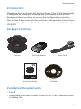
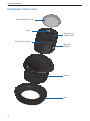
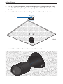
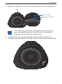
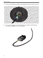
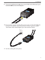
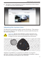
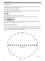
Security Camera
Introduction
Introduction
Thank you for purchasing the airCam Dome. This Quick Start Guide
is designed to guide you through the installation of the airCam
Dome and show you how to access the configuration interface.
The airCam Dome includes the airVision™ software. For instructions
on using the software, refer to the documentation included on the
CD‑ROM.
Package Contents
Camera
24V PoE Adapter
Power Cord
Security Camera
Quick Start Guide
CD-ROM
Installation Requirements
• Pencil
• Adjustable hole saw or other tool(s) to cut 73 mm diameter hole
in ceiling tile
1
airCam Dome
Hardware Overview
Removable Lens Cover
Lens
Manual Lens
Adjustment
AirCam Dome base
MicroSD
Card Slot
Bezel
Nut
2
Installation
LEDs
Ethernet LED
Power LED
Reset button
Ethernet The Ethernet LED will light steady green when
an active Ethernet connection is made and flash when
there is activity.
Power The Power LED will light steady orange when the
airCam Dome is connected to a power source.
Note: LED operation may be disabled using the camera
configuration interface.
Installation
1. (Optional) Insert a microSD card into the slot on the side of the
camera until it locks into the slot.
To remove the microSD card, push the card in to release the
lock. Pull the card out.
Note: Before removing the microSD card, be sure to
disable microSD recording to prevent file corruption.
3
airCam Dome
2. Cut a 73 mm diameter hole through the ceiling tile. You may
use the "Cutting Template" on page 12 of this Quick Start
Guide.
3. Insert the bezel into the ceiling tile and thread on the nut.
Nut
Bezel
4. Insert the airCam Dome base into the bezel.
4
Installation
5. Align the indicator on the camera with the arrow on the bezel.
Align
Arrow on bezel
Indicator on camera
Note: The airCam Dome is designed to be inserted
and removed when the indicator on the camera is
aligned with the arrow on the bezel.
6. Gently push the camera into the bezel and turn with one
motion as shown below. Rotate camera to the desired position
5
airCam Dome
7. Connect an Ethernet cable to the Ethernet port on the camera.
8. Connect the other end of the Ethernet cable to the Ethernet
port labeled POE on the PoE Adapter.
6
Installation
9. Connect an Ethernet cable from your LAN to the Ethernet port
labeled LAN on the PoE Adapter.
10.Connect the power cord to the power port on the PoE Adapter.
Connect the other end of the power cord to a power outlet.
The Power LED should light up on the airCam Dome.
11.Set the ceiling tile into place.
7
airCam Dome
Camera Configuration Interface
Verify connectivity in the Camera Configuration Interface.
1. Make sure that your host machine is connected to the same
LAN as the airCam Dome.
2. The airCam Dome is set to DHCP by default. If you have a
router or DHCP server providing addresses on your network,
check your DHCP Client Table to obtain the address of the
airCam Dome.
Note: If you do not have a DHCP server, the airCam Dome
defaults to the IP address 192.168.1.20.
4. Launch your Web browser and in the address field, type http://
and then the IP address of the airCam Dome, for example:
http://192.168.1.20. Press enter (PC) or return (Mac).
5. The login screen will appear. Enter ubnt in the Username and
Password fields and click Login.
8
Adjusting the Camera View
6. The Main screen will appear and you should see a live stream
of video from the airCam Dome.
Adjusting the Camera View
To adjust the camera lens angle, remove the dome . The camera
lens can be tilted 0 to 70°. Rotate the camera inside the bezel to
the desired position.
Important: Ensure the indicator on the camera is not
aligned with the arrow on the bezel (as shown in step
5, page 5) or the camera will detach from the bezel.
Hardware installation is complete. For details on using the
airVision software or the Camera Configuration Interface, refer to
the documentation included on the CD‑ROM.
9
airCam Dome
General Warranty
UBIQUITI NETWORKS, Inc (“UBIQUITI NETWORKS”) represents and
warrants that the Products furnished hereunder shall be free from defects
in material and workmanship for a period of one (1) year from the date
of shipment by UBIQUITI NETWORKS under normal use and operation.
UBIQUITI NETWORKS sole and exclusive obligation under the foregoing
warranty shall be to repair or replace, at its option, any defective Product
that fails during the warranty period. The expense of removal and
reinstallation of any item is not included in this warranty.
The foregoing warranty is exclusive and in lieu of all other warranties,
express or implied, including the implied warranties of merchantability
and fitness for a particular purpose and any warranties arising from a
course of dealing, usage or trade practice with respect to the products.
Repair or replacement in the manner provided herein shall be the sole
and exclusive remedy of Buyer for breach of warranty and shall constitute
fulfillment of all liabilities of UBIQUITI NETWORKS with respect to the
quality and performance of the Products. UBIQUITI NETWORKS reserves
the right to inspect all defective Products (which must be returned by
Buyer to UBIQUITI NETWORKS factory freight prepaid).
No Products will be accepted for replacement or repair without obtaining
a Return Materials Authorization (RMA) number from UBIQUITI NETWORKS.
Products returned without an RMA number will not be processed and will
be returned to Buyer freight collect. UBIQUITI NETWORKS shall have no
obligation to make repairs or replacement necessitated by catastrophe,
fault, negligence, misuse, abuse, or accident by Buyer, Buyer’s customers or
any other parties. The warranty period of any repaired or replaced. Product
shall not extend beyond its original term.
Warranty Conditions
The foregoing warranty shall apply only if:
(I)
The Product has not been subjected to misuse, neglect or unusual
physical, electrical or electromagnetic stress, or some other type of
accident.
(II) No modification, alteration or addition has been made to the Product
by persons other than UBIQUITI NETWORKS or UBIQUITI NETWORK’S
authorized representatives or otherwise approved by UBIQUITI
NETWORKS.
(III) The Product has been properly installed and used at all times in
accordance, and in all material respects, with the applicable Product
documentation.
(IV) All Ethernet cabling runs use CAT5 (or above) shielded cabling.
Disclaimer: UBIQUITI NETWORKS does not warrant that the operation of
the products is error-free or that operation will be uninterrupted. In no
event shall UBIQUITI NETWORKS be responsible for damages or claims
of any nature or description relating to system performance, including
coverage, buyer’s selection of products for buyer’s application and/or
failure of products to meet government or regulatory requirements.
10
Compliance
Returns
In the unlikely event a defect occurs, please work through the dealer or
distributor from which this product was purchased.
Compliance
FCC
This device complies with Part 15 of the FCC Rules. Operation is subject to
the following two conditions:
1. This device may not cause harmful interference, and
2. This device must accept any interference received, including
interference that may cause undesired operation.
The users manual or instruction manual for an intentional or unintentional
radiator shall caution the user that changes or modifications not expressly
approved by the party responsible for compliance could void the user’s
authority to operate the equipment.
Note: This equipment has been tested and found to comply with the limits
for a Class B digital device, pursuant to part 15 of the FCC Rules.
These limits are designed to provide reasonable protection against
harmful interference in a residential installation. This equipment generates,
uses and can radiate radio frequency energy and, if not installed and used
in accordance with the instructions, may cause harmful interference to
radio communications. However, there is no guarantee that interference
will not occur in a particular installation. If this equipment does cause
harmful interference to radio or television reception, which can be
determined by turning the equipment off and on, the user is encouraged
to try to correct the interference by one or more of the following measures:
• Reorient or relocate the receiving antenna.
• Increase the separation between the equipment and receiver.
• Connect the equipment into an outlet on a circuit different from that to
which the receiver is connected.
• Consult the dealer or an experienced radio/TV technician for help.
Industry Canada
This Class B digital apparatus complies with Canadian ICES-003.
Cet appareil numérique de la classe B est conforme à la norme NMB-003
du Canada.
11
airCam Dome
CE Marking
CE marking on this product represents the product is in compliance with
all directives that are applicable to it.
Alert sign! Follows CE marking
Alert sign must be indicated if a restriction on use applied to the product
and it must follow the CE marking.
NB-Identification number (if there is any)
Notified body number is indicated if it is involved in the conformity
assessment procedure.
Please check the CE mark on the product label to find out which notified
body was involved during assessment.
Cutting Template
To mount the airCam Dome in a ceiling tile, you will need to cut a
73 mm diameter circle in the ceiling tile. You can use the template
below as a guide for cutting the hole.
73 mm
RR101711
12
Ubiquiti Networks Support
Email: [email protected]
Phone (9 a.m. - 5 p.m. PST): 408-942-1153
Online Resources
Wiki Page: www.ubnt.com/wiki
Support Forum: www.ubnt.com/forum
Downloads: www.ubnt.com/support/downloads
www.ubnt.com
© 2011 Ubiquiti Networks, Inc. All rights reserved.