1
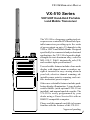
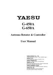
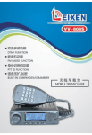
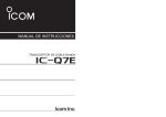
VX- 510
VHF/UHF Hand-Held Portable
Land Mobile Transceiver
OPERATING MANUAL
YAESU MUSEN CO., LTD.
1-20-2 Shimomaruko, Ota-Ku, Tokyo 146-8649, Japan
YAESU U.S.A.
17210 Edwards Rd., Cerritos, CA 90703, U.S.A.
YAESU EUROPE B.V.
Snipweg 3, 1118DN Schiphol, The Netherlands
YAESU UK LTD.
Unit 12, Sun Valley Business Park, Winnall Trading Estate
Winchester, Hampshire, SO23 0LB, U.K.
YAESU GERMANY GmbH
Am Kronberger Hang 2, D-65824 Schwalbach, Germany
YAESU HK LTD.
11th Floor Tsim Sha Tsui Centre, 66 Mody Rd.,
Tsim Sha Tsui East, Kowloon, Hong Kong
Congratulations!
You now have at your fingertips a valuable communications tool - a
two-way radio! Rugged, reliable and easy to use, your
radio will keep you in constant touch with your colleagues
for years to come, with negligible maintenance down time.
Please take a few minutes to read this manual carefully. The information presented here will allow you to derive maximum performance
from your radio. After reading it, keep the manual handy for quick
reference, in case questions arise later on.
We’re glad you joined the
team. Call on us any time, because
our business is communications. Let us help you get your message across.
NOTICE
There are no user-serviceable points inside this transceiver. All
service jobs must be referred to your Authorized Service Center
or Network Administrator.
VX-510 O PERATING MANUAL
VX-510 Series
VHF/UHF Hand-Held Portable
Land Mobile Transceiver
The VX-510 is a frequency-synthesized, microprocessor-controlled FM hand-held portable transceiver providing up to five watts
of power output on up to 32 channels in the
VHF or UHF Land Mobile Bands. Designed
specifically for commercial and professional
applications, the VX-510 is housed in highstrength die-cast aluminum alloy, sealed to
MIL-810 C, D & E intrinsically safe (I/S)
and weather-tight specifications*.
User selectable features include a four-mode
display with channel name or number, upright or inverted for easy viewing when on
your belt; selective channel scanning, adjustable-pause priority scanning, and variable transmitter power output.
Other user-selectable features include pushbutton display illumination, 2-tone decoder
enable/disable (with optional F2D-5 Unit
installed), and manual squelch override. The
VX-510 is easily programmed by your
dealer using a Yaesu Service Kit with an
IBM PC-compatible computer.
Please read this manual carefully to become
familiar with the features of the VX-510.
*approval pending
1
VX-510 OPERATING M ANUAL
SPECIFICATIONS
General
VHF (Low Band) VHF (High Band)
UHF
Frequency range (MHz):
29.8 – 38 MHz (vers.A)
38 – 50 MHz (vers.B)
Up to 32
(simplex or semi-duplex)
8.3 MHz (vers. A)
12 MHz (vers. B)
20 kHz (12.5 kHz optional)
5/6.25 kHz
16K0F3E (11K0F3E optional)
7.2 V DC 10%
50 mA (stby, saver off)
19 mA (stby, saver on)
200 mA (receive)
2000 mA (transmit)
59x149x39mm
570 grams
146 – 174 MHz
450 – 488 MHz
Up to 32
(simplex or semi-duplex)
28 MHz
Up to 32
(simplex or semi-duplex)
20 MHz
15/30 kHz
5/6.25 kHz
11K0F3E/16K0F3E
7.2 V DC 10%
50 mA (stby, saver off)
19 mA (stby, saver on)
200 mA (receive)
2000 mA (transmit)
59x149x39mm
570 grams
12.5/25 kHz
10/12.5 kHz
11K0F3E/16K0F3E
7.2 V DC 10%
50 mA (stby, saver off)
19 mA (stby, saver on)
200 mA (receive)
2000 mA (transmit)
59x149x39mm
570 grams
Double-conversion
Superheterodyne
21.6 MHz & 455 kHz
Double-conversion
Superheterodyne
47.9 MHz & 455 kHz
better than 0.25µV
better than 0.35µV
better than 0.20µV
65/75 dB
75 dB
72 dB
44/50 dB
+3/–8 dB from the 6 dB/oct.
De-emphasis curve
0.5 watts @16 Ω
better than 0.25µV
better than 0.35µV
better than 0.20µV
65/75 dB
75 dB
72 dB
40/45 dB
+3/–8 dB from the 6 dB/oct.
De-emphasis curve
0.5 watts @16 Ω
5W/1W
±2.5 ppm
variable reactance
±2.5/±5 kHz
TIA/EIA-603 3.2.6
better than –45/50 dB
60 dB below carrier
< 5% @60 % modulation
2-k Ω condenser
5W/1W
±2.5 ppm
variable reactance
±2.5/±5 kHz
TIA/EIA-603 3.2.6
better than –45/50 dB
60 dB below carrier
< 5% @60 % modulation
2-k Ω condenser
Channels:
Maximum Channel Spread:
Minimum Channel Spacing:
Programming Channel Step:
Emission Type:
Supply Voltage:
Current Consumption:
Case Size (WxHxD):
Weight (approx.):
Receiver
Receiver Circuit Type:
Double-conversion
Superheterodyne
Intermediate Frequencies:
21.6 MHz (ver. A)
16.9 MHz (vers.B)
& 455 kHz
12-dB SINAD Sensitivity:
better than 0.20µV
20-dB Noise Quieting:
better than 0.30µV
Squelch Threshould:
better than 0.18µV
Adjacent Channel Selectivity: 75 dB
Image Rejection:
80 dB
Intermodulation Response:
70 dB
Hum & Noise:
50 dB
+3/–8 dB from the 6 dB/oct.
Audio Response:
De-emphasis curve
AF output (for 5% THD):
0.5 watts @16 Ω
Transmitter
Power Output:
Frequency Stability:
Modulation System:
Maximum Deviation:
Audio Response:
FM Hum and Noise:
Spurious Emissions:
AF Distortion (@ 1 kHz):
Microphone Type:
5W/1W
±10 ppm
variable reactance
±5 kHz (±2.5 kHz optional)
TIA/EIA-603 3.2.6
better than –50 dB
60 dB below carrier
< 5% @60 % modulation
2-k Ω condenser
Specifications may be subject to change without notice or obligation.
2
VX-510 O PERATING MANUAL
ACCESSORIES & OPTIONS
MH- 30A2B
FNB-29A
CD-8
PA-14B
PA-14C
CS-500
ATL-1A
ATL-1B
ATL-1C
ATV-3B
ATV-3C
ATV-3D
ATV-3E
ATU-5D
ATU-5F
FVP-22
F2D-5A/B
FTT-7
FTT-7D
FTE-19
CE-21
VPL-1
VTP-20
CLIP-4
SBC-1
Speaker/Microphone
7.2 V/1700 mAh Ni-Cd Battery Pack
Desktop Battery Rapid-Charger (used w/PA-14B/C)
120 V AC Mains Adapter
230 – 240 V AC Mains Adapter
Overnight Desktop Charger
VHF Low Band Helical Flex Antenna (30 – 36 MHz)
VHF Low Band Helical Flex Antenna (36 – 42 MHz)
VHF Low Band Helical Flex Antenna (42 – 50 MHz)
VHF Helical Flex Antenna (148 – 155 MHz)
VHF Helical Flex Antenna (150 – 162 MHz)
VHF Helical Flex Antenna (155 – 164 MHz)
VHF Helical Flex Antenna (162 – 174 MHz)
UHF Helical Flex Antenna (450 – 470 MHz)
UHF Helical Flex Antenna (470 – 512 MHz)
Encryption Unit
Two-Tone Sequential Decoder
DTMF Keypad Tone Generator (16 keys)
DTMF Keypad Tone Generator w/Decoder
ANI (Auto Numbering Identification) Unit
Programming Software
Programming Cable
VX-Trunk II VX-Trunking Portable Logic Board
Belt Clip
Swivel Belt Adaptor (Requires LCS-2)
3
VX-510 OPERATING M ANUAL
CONTROLS & C ONNECTORS
Top panel
‡F
‡G
‡E
‡D
‡@
‡A ‡B ‡C
(1) VOL Control
This control adjusts the volume of the receiver, and turns the radio off
when rotated fully counterclockwise to the click-stop
(2) S/DW Button (Scan/Dual Watch)
Momentarily (< 1sec.) pressing this button turns the channel scanner on
and off. Pressing and holding (> 1 sec.) this button activates the Dual
Watch feature (explained later).
(3) B Button
Pressing and holding this button more than 2 seconds (but less than 4
seconds) activates functions as programmed by your dealer and determined
by your system requirements (See “PRE-PROGRAMMED FUNCTIONS”, page
13). Pressing and holding this button more than 4 seconds inverts the
LCD display to either frontward or backward facing readout (the backward display is convenient for viewing when wearing the transceiver on
your belt).
4
VX-510 O PERATING MANUAL
CONTROLS & CONNECTORS
(4) A Button
Pressing and holding this button more than 2 seconds (but less than 4
seconds) also activates an assigned function (programmed by your dealer).
Pressing and holding this button more than 4 seconds causes the selected
channel to be assigned as the Priority Channel for use with Priority Scanning and Dual Watch functions (explained later).
(5) BUSY/TX Indicator
This lamp blinks green when a signal is being received (or the squelch is
opened by pressing the MON RES button) and red when transmitting. To
avoid interference, do not transmit if the lamp is glowing green. When the
battery almost depleted, this lamp blinks red, indicating that the battery
needs recharging or replacement very soon.
(6) CH Rotary Selector
This rotary switch selects the operating channel. If a channel is selected
” is displayed, accompathat is not available for operation, “
nied by a rapid warning beeper (2 beeps/sec.).
""""
(7) Antenna Jack
This threaded-type jack accepts the supplied flexible antenna. Any other
antenna types used here must be designed for the programmed operating
frequencies.
(8) Liquid Crystal Display
In addition the channel number name, the display includes some operating
status symbols, indicated in the diagram below.
5
VX-510 OPERATING M ANUAL
CONTROLS & C ONNECTORS
Side Panel Buttons
‡@
‡A
‡B
‡D
‡C
‡E
(1) MON RES (Monitor/Reset) Button
Pressing and holding this button more than 2 seconds (but less than 4
seconds) disables the tone squelch, and permits monitoring of stations
transmitting on the selected channel while still keeping your receiver quiet
from noise (“MO ” will appear at the top right of the LCD). Press it again
to only hear calls within your network.
Pressing and holding this button more than 4 seconds toggles the tone and
noise squelch override, allowing all stations (and noise) on the channel to
be heard. This may be used to hear weak stations whose signals would not
normally open the squelch. Do this to pre-adjust the VOLume control
before receiving calls.
6
(With Selective Calling Option)
When the two-tone sequential decoder unit (F2D-5) is installed, and a
selective call has been received (“CALL” indicator on), pressing and
holding this button more than 2 seconds (but less than 4 seconds) will
reset the call function on the current channel and silence the receiver,
otherwise pressing and holding this button more than 4 seconds resets the
call function on ALL channels.
VX-510 O PERATING MANUAL
CONTROLS & CONNECTORS
(2) PTT (Push-To-Talk) button
Hold this button to transmit (the “BUSY/TX” indicator glows red).
(3) LAMP/LOCK button
Press this button momentarily (<1 sec.) to illuminate the display for five
seconds. Pressing and holding (>1 sec.) this button locks top-panel pushbuttons (S/DW, B, A, and the optional DTMF keypad); this can be enabled to prevent radio settings from being disturbed.
(4) Battery Release button
Slide this button in the direction of the arrow (upward) for battery removal.
(5) EAR Jack
This provides audio output for an earphone or the optional MH- 30A2B
External Speaker/Microphone here. The internal speaker is disabled when
a plug is inserted into this jack.
(6) MIC Jack
Connect the optional MH-30A2B Speaker/Microphone here, the internal
microphone is disabled when this jack is used.
7
VX-510 OPERATING M ANUAL
OPERATION
Preliminaries
If the transceiver has not been used since leaving the factory, fully charge
the battery using CD-8 unit (with PA-14B or C) before using it.
Mount the battery on the transceiver as described and shown in the photo
below. Also, install the antenna on the jack on top of the transceiver by
screwing the connector into the jack until it is finger-tight.
Battery Removal & Replacement
¦ Make sure that the VOL control is set into the off click-stop, and
remove the protective soft or hard case, if used.
¦ Grasp the transceiver with your left hand, so your palm is over the
speaker and your thumb is on the Battery Release Button.
¦ Move the button in the direction indicated by the arrowhead, while
using your right hand to slide the battery pack toward the side with
the button. The battery pack should slide smoothly out of its track.
¦ To replace the Ni-Cd pack, repeat the second and third steps above,
simply sliding the battery case in the other direction after aligning
the shorter side of the battery pack with the track below the Battery
Release Button.
8
VX-510 O PERATING MANUAL
OPERATION
Preliminary Steps
Before operating the transceiver for the first time:
¦ Charge the battery pack and connect the supplied helical rubber
flex antenna to the antenna jack on the top of the transceiver. Never
operate the transceiver without an antenna connected.
¦ If you have a Speaker/Mic, we suggest you do not connect it until
you are familiar with basic operation.
¦ Before proceeding, please review the “Top & Side Panel Controls”
outline, if you have not already, to familiarize yourself with the
functions of the controls.
Basic Operation
r Switch on the transceiver by rotating the VOL control clockwise
out of the click-stop (a momentary beep will sound). For now, adjust the control to about mid-position (12-o’clock), later you can
adjust the level to suit the operating environment.
r Rotate the CH knob to select a channel for operation, the LCD will
” is displayed,
show the currently selected channel. If “
along with a rapid (2 beeps/sec.) beeping tone, the selected channel
position is not available for operation.
r To transmit, wait until the channel is clear (“BUSY/TX” LED off),
then press in the PTT switch on the side of the transceiver while
speaking across the face of the radio. A clear normal voice will
provide the best quality transmission. For maximum battery life,
select low power output (covered later) whenever possible. During
transmission the “BUSY/TX” indicator glows red. Release the PTT
switch to receive.
r To receive weak stations better, try positioning the radio as high
and far away from your body as possible, or disable the squelch
momentarily by holding the MON RES button on the side of the
radio for > 4 sec. (until the second low/high beep sounds). With the
squelch disabled, the “BUSY/TX” indicator will blinks green and
channel noise and weak stations can be heard. To quiet the radio
again, press the MON RES button again momentarily.
r When you are done operating, be certain to turn the VOL control to
the off position to conserve battery life.
""""
9
VX-510 OPERATING M ANUAL
OPERATION
An important note about your radio !
Some of the radio/button functions discussed next will only operate in
your radio if so programmed by your dealer, or after the installation of
certain internal optional units. In this way, the radio’s operation can be
simplified and customized specifically for the user according to network requirements. If pressing a button on your radio does not result
in the same function described in this manual, or if you are uncertain
of the functions your particular radio is configured with, contact your
dealer. See “PRE-PROGRAMMED FUNCTIONS” on page 13.
Scanning
Scanning allows you to sequentially check for calls on all or only those
channels you select. To start scanning, press the S/DW button momentarily. A beep then sounds and the display will clear and show “ SCAN”.
Scanning will pause when a signal is received, at which time the channel
number (or alphanumeric tag) will be displayed. A small “S ” will be displayed above the channel, indicating the scanner is still active, but paused.
During this pause, you can press the PTT switch and talk to the station.
Otherwise, scanning will resume a few seconds after the signal is no longer
present. While scanning, if you momentarily press the PTT switch, operation automatically shifts to a default channel. This default channel can be
set to the priority channel (both “P ” and “S/DW ” are displayed), lastbusy channel, or home channel, depending on how your radio was programmed.
To stop scanning, simply press S/DW momentarily again. Operation will
return to the channel that was last selected when scanning was activated.
If enabled by dealer programming, you may select only the channels you
want to scan, and have others skipped-over by performing the following
routine.
Turn the radio OFF, then depress the S/DW button while turning the radio
back ON again. “PROG” will momentarily appear on the display, after
which it will revert to the currently selected channel (this indicates you
are in the programming mode). If user-access is disabled “INH” will appear briefly.
10
VX-510 O PERATING MANUAL
OPERATION
Use the CH knob to select a channel, then press the S/DW button to enable the channel for scanning (“ E ” will appear in the upper left corner of
the LCD). Repeat this process for each channel you want the scanner to
check.
To remove a channel from those to be scanned, press S/DW again, so that
“E ” no longer appears in the display.
After you have enabled all the channels you want to scan, turn the radio
off, then on again to return to normal operation.
Priority Scanning
Priority scanning allows you to scan and monitor channels while the receiver periodically checks for calls on a pre-selected (“priority”) channel.
You may want to use this feature if you want to scan different channels,
but don’t want to miss a call for you on a primary dispatch, emergency or
tactical frequency. After a call has been received on the priority channel,
operation returns to the programmed default channel scheme, as mentioned
before. Only one channel at a time can be selected as the priority channel.
¦ To set the currently displayed channel as the priority channel, just
press and hold the A button for 4 sec. A small “ P ” will now appear
at the top left corner of the display whenever this channel is selected, along with an accompanying “beep”.
When a priority channel has been selected, the scanner will check the
priority channel regularly as you scan the other channels. If a signal appears on the priority channel, the scanner will pause and operation will
jump to the priority channel. Otherwise, the scanner will pause on active
non-priority signals as previously described.
If a call comes in on a non-priority channel that you need to respond to,
just press the PTT switch while the scanner is paused on that channel. As
long as no call comes in on the priority channel, you can send and receive
on the other channel: scanning will resume when you finish and the channel clears.
11
VX-510 OPERATING M ANUAL
OPERATION
Dual Watch
If you need to operate on a non-priority channel while still checking for
calls on the priority channel, the Dual Watch feature let’s you to do this
without using the scanner. When enabled, operation on any selected nonpriority remains normal as before, however, when a signal is received on
the priority channel or when you press the PTT switch, operation immediately shifts to the priority channel. The rate at which the Dual Watch feature samples the priority channel can be set by the user.
¦ To begin Dual Watch operation, first assign a priority channel as
described before, then select the non-priority channel you wish to
operate on.
¦ Press and hold the S/DW button until the second beep sounds,
“DW ” (but not “S”) will appear at the top of the display.
¦ To manually shift to the priority channel, press the PTT switch. At
this time you make transmit, otherwise, if no signal is received within
2 seconds, operation will revert back to the other selected Dual Watch
channel.
¦ To turn off the Dual Watch Feature, press and hold the S/DW button again (“DW ” will disappear in the display).
Low Battery Power Indication
When the rechargeable Ni-Cd battery pack voltage reaches a low level,
the “ x ” indicator appears at the lower right corner of the LCD, and
the “BUSY/TX” indicator will blinks red. Immediately remove the
Ni-Cd pack and install a freshly charged battery pack, or insert the
radio into the charging stand for a complete recharge cycle. If you
plan to operate your radio for extended periods of time, you may want
to keep a spare, fully-charged pack handy.
12
VX-510 O PERATING MANUAL
PRE-PROGRAMMED FUNCTIONS
The function selected by pressing and holding the A or B button more
than 2 seconds (but less than 4 seconds) can be customized by dealer programming and your network requirements. A brief explanation of available functions is provided below. However, contact your dealer for details
on their use and operation.
Low Transmit Power
This reduces the power output of your radio to approximately one watt to
conserve battery life, and when full power is not needed to maintain reliable communications. “ LO ” will be displayed at the upper right corner
when enabled.
Alpha Tag
This displays an alpha-numeric channel name , usually describing the channel, rather than merely displaying a channel number. These may be programmed to assist you in recognizing channels by name, rather than by
memorizing channel numbers and their assignments.
Talk Around
This feature enables simplex operation on semi-duplex channels: the transmit frequency becomes the same as the receive frequency (regardless of
any programmed offset for the channel).
Note: This feature has no effect on simplex channels.
Channel Group Selection
The 32 available channels in the VX-510 can be organized into 2 groups
with up to 16 channels in each. Pressing and holding this button more than
2 seconds (but less than 4 seconds) lets you select a group for operation.
Channels within each group are selected using the rotary dial.
Optional Accessory
Voice Encryption (FVP-22):
When installed, pressing and holding this button more than 2 seconds (but
less than 4 seconds) will turn on the optional voice encryption unit for
privacy during communications.
ENI (Emergency Numbering Identification) Unit (FTE-19):
When installed, pressing and holding this button more than 2 seconds (but
less than 4 seconds) will turn on the optional ENI Unit, then within 1/2
second, press this button again to transmit the ENI signal.
13
VX-510 OPERATING M ANUAL
BUTTON FUNCTIONS
As mentioned before, button functions can be customized by programming from your Yaesu dealer to meet your communications/network requirements. Some features may require the purchase and installation of
optional internal accessories for operation. The table below illustrates the
possible Top-panel button programming combinations. Functions are explained on the previous page “PRE-PROGRAMMED F UNCTIONS.” For further
details contact your nearest Yaesu dealer. For future reference, check the
box next to the function that has been assigned to the button on your particular radio, and keep it handy.
Press and Hold
(< 2 seconds)
A Butto n
r
r
r
r
r
r
Channel Group
HI/LOW TX Power
Alpha Tag
Talk Around
Accessory (Voice Encryption)
Accessory (ENI)
Tags currently selected channel
as the Priority Channel
B Butto n
r
r
r
r
r
r
Channel Group
HI/LOW TX Power
Alpha Tag
Talk Around
Accessory (Voice Encryption)
Accessory (ENI)
Toggles the Top Panel LCD
display between normal and
inverted readout
Press
momentarily
(< 1 secon d)
S/DW
Button
14
Press and Hold
(> 4 seconds)
Starts/Stops
Channel Scanning
Press and Hold
(> 1 secon d)
Starts/Stops
Dual-Watch
Feature
Press and Hold
while Power-o n
User-selectable channel
scanning programming
(if enabled)
VX-510 O PERATING MANUAL
CUSTOM SETTINGS
Below is a table of radio features that can be customized by dealer programming. To change a feature as your requirements change, contact your
Yaesu dealer. For future reference, check the box next to the option that
has been programmed in your particular radio, and keep it handy.
Feature
Options
Explanation
r Enabled
r D isabled
Channel scanning can be disabled
completely for system s not requiring this
feature.
Scan-Stop
R esume
r 5-seconds
r C arrier
In the 5-seconds mode, scanning pauses
on a busy channel for 5 seconds, then
resum es.
In t he Carrier m ode, scanning pauses and
remains on a busy channel until t he
station stops transmitting.
U ser-Scan
Program
r Enabled
r D isabled
If enabled, t he user can program w hich
channels are to be scanned; otherwise,
dealer-program mable only.
D ual
Watch
r Enabled
r D isabled
D ual-Watch can be disabled com pletely for
systems not requiring this f eature.
C hannel
after PTT
r Priority C h.
r H ome C h.
r Last-Busy
If the PTT is pressed during scanning,
determines which default channel the radio
returns to : the selected Priority C hannel,
a designated "H om e" Channel, or the
channel that w as last-busy.
Monitor
r Enabled
r D isabled
Enable/Disable the side-panel MON R ES
button (See pages 6 & 9).
A/B Button
See Table
Flexible dealer-programming as outlined in
the table on the previous page.
C hannel
Scan
15
VX-510 OPERATING M ANUAL
RECEIVER SQUELCH SETTING
The squelch setting on your VX-510 is preset at the factory, and does not
normally require re-adjustment. However, in the event that this should
become necessary:
To adjust the squelch, use the Allen wrench to loosen the setscrew securing the VOL knob, then pull off the VOL knob. Rotate the small brass
collar just above the base of the VOL control shaft, using a pair of tweezers, as shown below. Be careful not to loosen the larger mounting nut at
the base of the control. When done, rotate the VOL control shaft fully to
the counter-clockwise position (into the click-stop), and press the VOL
control back on the shaft to align the indicator of the VOL control to the
dot “ l” on the top panel, then tighten the setscrew.
Adjustment of this control affects whether your radio can hear distant and
nearby stations, or only nearby ones; therefore we recommend leaving the
control as set, or having your Yaesu dealer perform the adjustment.
16
VX-510 O PERATING MANUAL
INSTALLING CHANNEL-STOPS
To simplify operation and prevent selection of unprogrammed/unused
channels or channel groups, tiny metal inserts or “stops” can be inserted
into the top panel beneath the CH selector knob. A tiny tab protruding
from beneath the skirt of the CH knob engages the stop(s) as it is turned,
preventing further rotation.
To insert a stop, rotate the CH knob to the channel “1” position and use
the Allen wrench to loosen the setscrew locate the CH knob, then pull off
the CH knob. Insert the stops firmly into the appropriate slot(s) for the
desired channels, using a pair of tweezers or fine needle-nose pliers, according to the drawing below. For example, to limit CH selection to channels 1 - 4, insert one metal stop at the 9 o’clock position (slot), and the
other at the 6 o’clock position. When done, press the CH selector knob
back on the shaft, align the indicator of the CH knob to channel “1,” then
tighten the setscrew.
Note: The use of mechanical stops should not be used or relied upon as the
sole means to prevent selection or transmission on an invalid or unauthorized channel. Channels should be locked-out or TX-inhibited via programming by your Yaesu dealer, and stops inserted as a operating convenience to you and your network users.
17
VX-510 OPERATING M ANUAL
UNDERSTANDING RADIO WAVES
Radio waves travel from one point to another by several different means. The
general term for these methods of wave travel is “propagation”. You may
know that “shortwave” signals can be propagated over distances of several
thousand miles by reflection off of the upper regions of the atmosphere.
Your hand-held transceiver, on the other hand, operates on the so-called VHF
(Very-High Frequency) and UHF (Ultra-High Frequency) bands. On these
bands, radio waves usually do not reflect off of the atmosphere. Instead, the
radio waves behave almost as light: they travel in a straight line, and when
they meet a building or obstruction, they go no further in that direction.
Therefore, it is important that you be as high and free from obstructions as
possible to cover the greatest distance when using your radio. If you operate
from inside a car or building, any metal around you can absorb much of the
signal, both transmitted and received. Coverage may therefore be very poor
under those conditions. However, if you must operate from indoors, moving
next to a window will improve communications.
In view of the factors just discussed, you can easily see the potential benefit
of holding the radio up high near your mouth while transmitting. In this way
the antenna is high and clear, and coverage is best.
On final note regarding propagation is useful in improving coverage. Because radio waves at VHF and UHF are similar to light waves, they do reflect,
to varying degrees, off of hills, buildings, and the like. In a crowded urban
area, with many close buildings close together, many reflections may occur,
and interfere with one another, causing variations in signal strength at different locations.
Therefore, if a signal is weak and you walk a few feet in any direction, reception may suddenly become
clear, because a particular
reflection path may become dominant. Reflections are frequently useful,
as they can allow for communications between two
stations over a highly obstructed path.
18
This device complies with Part 15 of the FCC rules.
Operation is subject to the condition that this device
does not cause harmful interference.
RADIO COMMUNICATIONS
Copyright 1998
Yaesu Musen Co., Ltd.
All rights reserved.
Printed in Japan
No portion of this manual
may be reproduced
without the permission of
Yaesu Musen Co., Ltd.