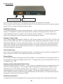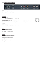
1
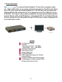
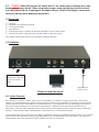
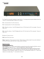
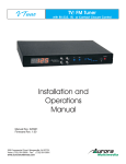
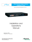
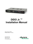
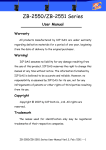
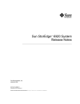
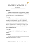
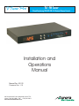
V Tune Pro
TV/ FM Tuner
Closed Captioning, OSD, RS-232, IR, Contact Closure Control
Installation and
Operations
Manual
Manual Rev: 031115
Firmware Rev: 1.10
205 Commercial Court Morganville, NJ 07751
Voice: (732) 591-5800 Fax: (732) 591-5801
www.auroramultimedia.com
Table of Contents
Product Description ................................1
Warning ................................................. 2
Unpacking ............................................ 2
Installation ............................................. 2
System Overview ................................... 2
Remote Control .................................... 3
Front Panel ............................................ 4
Setup Mode . ........................................ 5
Specifications ........................................ 7
Control Port ............................................ 8
RS-232 Protocol ..................................... 9
Connector Specifications ..................... 11
Troubleshooting .................................... 12
Upgrading Firmware ............................. 13
Warranty
............................................ 14
FCC Statement ..................................... 15
1.0 Product Description
The VTune Pro is a 181-channel Closed Caption TV Tuner with composite video
out. Built in OSD allows for on-screen channels and volume. The VTune Pro allows
up to 999 units to be connected together via 1 RS-232 port and the advanced
addressable RS-232 command set. It is a perfect low cost TV or FM Tuner for any
AV System. The VTune is also a great compliment to stand alone display devices
such as Plasma, LCD, and CRT displays. Using the RS-232, IR, or Contact Closure
Control ensures that this affordable compact TV/FM Tuner is easily integrated into
any audio/video system.
+
or
Plasma Display
Features
? 181 Channel TV Tuner
? FM Tuner:
North America (87.5 - 107.9MHz)
International (87.4 - 108.0MHz)
? Composite Video Output
? Stereo Audio Output
? Closed Captioning
? On Screen Display
? 2 RS-232 ports for looping, IR, Contact
Closure Control
? Includes Full Featured IR remote control
? Customizable for control of other RS-232
Devices (call Aurora for info)
-1-
LCD Projector
Caution: Static (Still) pictures will cause “burn in” on certain types of displays and may
2.0
damage the display device. When using static images, reducing brightness and/or contrast
can help reduce the risk of damage to the display device. Refer to the display’s owners and
technical manual about additional precautions.
3.0 Unpacking
(1) - VTune Pro
(1) - Installation and Operations Manual
(1) - 12 Volt power supply
(1) - IRC-2 Remote
(1) - 6 Pin Mini DIN Male - Female 9 Pin (Firmware Upgrade / RS-232 Control Cable)
(1) - 6 Pin Mini DIN Male - 6 Pin Male (Loop through cable for multi-unit control)
Note: Please examine the VTune Pro for any signs of shipping damage.
4.0 Installation
For RS-232 Control use
the provided 6 pin mini
DIN to 9 pin female
cable.
Display Device
Antenna Input
(Cable TV, etc.)
VTune Pro Setup/Connection
5.0 System Overview
The VTune Pro is an RS232, contact closure, and IR controllable 181 Channel TV Tuner and FM Tuner. The unit was
designed for easy integration into systems that need remote control of the capabilities. The powerful yet simple RS232
protocol gives a user full 2 way feedback of channel selections. Control systems can take advantage of the RS232 to
allow true channel updating on a touch panel or web browser. Ordinary IR only tuners can not give this type of
information. Kiosks can take advantage of the contact closure port for direct access of channel, volume, and source
selection. Twelve built in presets make getting to a users favorite TV or FM channels a breeze.
Another great feature of the VTune Pro is the ability to upgrade the firmware for additional features or fixes. Try to keep an
eye out for the latest releases on www.auroramultimedia.com to take advantage of the new version. The firmware is
easily upload to the VTune Pro with the Flash123 utility that is free on our web site.
-2-
6.0 Remote Control
Using the Aurora IRC-7 Remote Control
POWER
V Tune Pro
F1
1
F2
F3
MUTE
2
3
4
5
CC
EDS
AUDIO
8
9
10
TV
VOL
6
FM
13
11
15
12
17
MENU
INFO
18
19
14
CH
7
1
2
3
4
5
6
7
8
9
20
23
26
21
24
27
SET
25
28
LAST
0
31
P1
P2
P3
32
33
34
P4
P5
P6
35
36
37
P7
P8
P9
38
39
40
P10
P11
P12
41
42
43
Presets
Source Selection
11. TV INPUT - Selects the TV Antenna as the Main source
12. FM INPUT - Selects the FM Antenna as the Main source
22
30
29
5. MUTE - Toggles the volume mute on/off
6. VOLUME - Ramps the volume up or down
7. CHANNEL - Changes the TV channel + or 8. CC - Closed Captioning 1 & 2
9. EDS - Extended Data Service
10. AUDIO - Not Used (Future use)
16
SELECT
1. POWER - Turns on and off the VTune
2. F1 - See Setup Mode section for detail
3. F2 - See Setup Mode section for detail
4. F3 - See Setup Mode section for detail
13. UP ARROW - Not Used (Future use)
14. DOWN ARROW - Not Used (Future use)
15. LEFT ARROW - FM Scan 16. RIGHT ARROW - FM Scan +
17. SELECT - Confirms selection. Entering Channel 12 then Select
will immediately change the channel as compared to waiting for the 3
second time out.
18. MENU - Not Used (Future use)
19. INFO - Displays current channel and volume level
20 - 29 Number Keys - Used for direct channel selection
30. SET - Pressing this and one of the Preset buttons within 1.5
seconds stores current channel.
31. LAST - Returns to the last channel selected
IRC-7
Preset Selections
32 - 43 Preset Keys - P1 thru P12 selects the stored preset for TV or
FM.
-3-
7.0 Front Panel
The VTune Pro front panel is simple but very effective. The orange seven segment display shows the
current TV channel selected for Main or PiP channel.
Ch+: Increments the TV or FM channel up
Ch-: Decrements the TV or FM channel down
Vol+: Raises the volume. Front LED display will show v 52 if the level is at 52 for example. Times out
after 3 sec.
Vol-: Lowers the volume. Front LED display will show v 52 if the level is at 52 for example. Times out
after 3 sec.
TV: Selects TV as the source
FM: Selects FM as the source
Power: Toggles the VTune power on and off. When turning on it takes about 2 seconds to initialize. If
the VTune Pro loses power it will turn on when power is returned.
Special Functions:
TV & Vol- pressed together:
North America: With TV as the current selection, pressing theses buttons together will allow a user to
select broadcast, cable, HRC, IRC. The LED will display the selection with text.
International: With TV as the current selection, pressing theses buttons together will allow a user to
select the country code: AU (C01), EE (C02), FR (C03), GM (C04), NZ (C05), UKA (C06), UKC (C07),
Netherlands (C08), Switzerland Cable(C09), Russia (C10), and Switzerland Cable 2(C11). The LED will
display the corresponding “C” code selection with text.
-4-
8.0 Setup_Mode
Add/Delete Channels. LED
is lit if the channel is added.
LED will be lit if in setup
mode.
To access setup mode press the following remote sequence quickly: SET, UP, DOWN
When in setup mode the right most decimal will be lit. To exit setup mode cycle the power using the
power button or unplug and plug the power cable.
Add/Delete Channels
If TV is selected then the current channel will appear. The left most decimal will be lit if the channel is
added. To add/delete channels use the left arrow to delete and the right arrow to add for the
current displayed channel. To get to other channels use the channel +/- or numeric keypad (US
version only. Keypad is used for frequency setup on international version.)
TV Setup / Country Code
The F1 button toggles through BCST, CABLE, IRC, HRC for the US and AU (C01), EE (C02), FR (C03), GM
(C04), NZ (C05), UKA (C06), UKC (C07), Netherlands (C08), Switzerland Cable(C09), Russia (C10), and
Switzerland Cable 2(C11) for the international version. The country code for the international version
sets up PAL or SECAM and the type of audio used for the country. The frequency per channel will
need to be entered in per channel based on location. A typical frequency chart can be found on
the Aurora website for download.
Auto Channel Learn
The F3 button will add/delete the strongest channels. If no stations can be tuned try changing the TV
Setup using the F1 button. This currently works only for the US version.
Device Address
The F2 button will allow changing off the device address. Once pressed the up and down arrows or
the keypad will change the address from 0 to 999. If a single unit is to be controlled RS-232 then use
0, otherwise use 1-999.
Frequency Setup (International Version Only)
Select the channel using the channel +/- only. Once on a channel use the up or down arrow to see
what the current frequency is. Even though 4 digits are displayed it shows the first 4 digits of the 5
digit frequency. Ex. 800.25MHz will show 800.2 on the display. To change the frequency use the
number keypad to enter the freq as if it was 5 digits. If the wrong value is entered or if too much
time is taken to enter the number the VTune will revert back to the old freq. The up/down arrows will
increment or decrement the freq by 100KHz.
FM Volume & Auto Mute
To adjust the FM Volume separately of the main volume to balance the TV level with the FM level
-5-
8.0 Setup_Mode (Continued)
press the FM button. Use the volume +/- to adjust the level. Switch back and forth between a
tuned TV channel and a tuned FM channel until it sounds close to the same level. The mute button
will toggle the auto FM mute function. If the station is weak the auto mute will turn off the audio
instead of having to listen to static. This feature may be disabled to listen to weaker stations with
static.
-6-
9.0 Specifications
RF Tuner (North America)
Input Connector : 'F' type female
TV Frequency Range : 55.25 to 801.25 MHz, 31.25 or 62.5KHz fine tune
FM Frequency Range : 76.00 to 108.00 MHz, 50KHz fine tune
Demodulation: Quasi-Split Sound concept
RF Tuner (International)
Input Connector : 'IEC' type female
TV Frequency Range : 48.25 to 855.25 MHz, 31.25/50.0, or 62.5KHz fine tune
FM Frequency Range : 76.00 to 108.00 MHz, 50KHz fine tune
Video Output
Connector: RCA female Yellow
Output: Composite video
Impedance: 75 ohms
Typical Level: 1.0V peak-peak into 75 ohms
Audio Outputs
Connectors: 2 RCA female
1- Left (White) 1- Right (Red)
Output: Unbalanced line level
Output Level: +12dB to –114dB in 64 steps
Dimension
8.4”L x 5.65”D 1”H
Power
12v DC
Compliance
FCC Class B
CE EN 55013:2000
CE EN 55024:1998
CE EN 60065
Specifications subject to change without notice.
-7-
10.0 Control Port
RS232 - Pins 1,3,5
Pin 1 - Ground
Pin 3 - TX
Pin 5 - RX
Contact Closure - Pins 1,2,4,6
Pins 1,2: TV
Pins 1,4: Channel +
Pins 1,4,6: FM
Pins 1,2,4: Volume +
Pins 1,6: Channel Pins 1,2,6: Volume -
11.0 RS-232 Protocol
Baud Rate: 9600 8N1
Note: Protocol below is as of firmware version 1.10 New commands will be available on future
revisions to give more discrete full featured commands. Check on the Aurora website for the latest
firmware and RS232 command additions.
The VTune Pro is addressable. This allows multiple VTune Pro units to be connected together via
the loop port. When using commands with an address of 001 to 999 after the “!” the auto
feedback from changes in the volume, channel, etc will no longer work to prevent collision.
Polling should be used. Also, “error” will not be sent unless it is specific to an address. When
address 0 is used all auto feedback will work. If the commands below are not sent with a three
digit address after the ”!” And multiple devices are connected via loop port then all devices will
respond which is not good practice as collisions will occur. A response will occur when a
command is sent with an address except it will now include the address of the unit replying. To
talk to all units at the same time with no response use “***” in place of the 3 digit address. This
is useful when multiple units are to be set to a channel or volume level.
Eg.
!001KEY_LEFT<CR> will tell unit addressed with 001 to carry out the key left command
~001KEY_LEFT<CR> will be the response from the VTune Pro
!***KEY_CH+<CR> will tell all units to increment the TV channel by 1 but there will be no
response
? IS A QUERY COMMAND
! IS A COMMAND
~ IS A RESPONSE
(Does not have to be Case Sensitive)
(Does not have to be Case Sensitive)
(ALL RESPONSES ARE CAPITALS)
<CR> is 0D hex or 13 decimal
!KEY_LEFT<CR>
!KEY_RIGHT<CR>
!KEY_UP<CR>
!KEY_DOWN<CR>
!KEY_SEL<CR>
!KEY_CH-<CR>
!KEY_CH+<CR>
!KEY_LAST<CR>
!KEY_0<CR>
!KEY_1<CR>
!KEY_2<CR>
!KEY_3<CR>
!KEY_4<CR>
!KEY_5<CR>
Left
Right
Up arrow key
Down arrow key
Select
Channel Down
Channel Up
Toggles between the last 2 channels selected
0
1
2
3
4
5
-8-
11.0 RS-232 Protocol (Continued)
!KEY_6<CR>
!KEY_7<CR>
!KEY_8<CR>
!KEY_9<CR>
!KEY_SET<CR>
!KEY_P1<CR>
!KEY_P2<CR>
!KEY_P3<CR>
!KEY_P4<CR>
!KEY_P5<CR>
!KEY_P6<CR>
!KEY_P7<CR>
!KEY_P8<CR>
!KEY_P9<CR>
!KEY_P10<CR>
!KEY_P11<CR>
!KEY_P12<CR>
!KEY_VOL+<CR>
!KEY_VOL-<CR>
!KEY_MUTE<CR>
!KEY_PWR<CR>
!KEY_F1<CR>
!KEY_F2<CR>
!KEY_F3<CR>
!KEY_TV<CR>
!KEY_FM<CR>
!KEY_MENU<CR>
!KEY_INFO<CR>
!KEY_CC<CR>
!KEY_EDS<CR>
!KEY_AUDIO<CR>
!PWRON<CR>
!PWROFF<CR>
?PWR<CR>
!VOLxx<CR>
?VOL<CR>
?MCH<CR>
!MCHxxx<CR>
?MIN<CR>
!FCHxxxx<CR>
?FCH<CR>
?VER<CR>
?ADDR<CR>
!ADDRxxx<CR>
!CC1<CR>
!CC2<CR>
!CCOFF<CR>
?CC<CR>
?AFC<CR>
6
7
8
9
Set button for presets
Preset 1
Preset 2
Preset 3
Preset 4
Preset 5
Preset 6
Preset 7
Preset 8
Preset 9
Preset 10
Preset 11
Preset 12
Volume up
Volume down
Volume mute
Power On / Off
Future use.
Future use.
Future use.
TV Source Selection
FM Source Selection
MENU
Info
Closed Captioning
Extended Data Services
Audio
Power On
Power Off
Query Power status responds with ~PWRON<CR> or ~PWROFF<CR>
Volume Level Set xx=00 to 64 Responds with ~VOL52<cr> for volume level 52.
00 is Mute for this command. 52 is zero dB
Query Volume Level Responds with ~VOL10<CR> for volume level 10.
Query Main Channel Responds with ~MCH002<CR> for channel 2.
Main TV Channel change !MCH025<CR> for channel 25. xxx = 001 to 125
Main Input Query responds with ~MTV<CR> or ~MFM<CR>
FM Channel Selection. !FCH0987<CR> for 98.7fm.
Query FM Channel responds with ~FCH0987<CR> for 98.7fm.
Version Query responds with ~VER 1.00<CR> if version 1.00 was present.
Query Device Address Responds with ~ADDR001<CR> for address 1.
Device Address change !ADDR015<CR> for address 15. xxx = 000 to 999
Closed Caption 1 selection
Closed Caption 2 selection
Closed Caption Off selection
Query Closed Caption responds with either ~CC1<CR>, ~CC2<CR>,
~CCOFF<CR>
responds with ~AFCxx<CR> xx=2 digit ASCII decimal equivalent
Bit 7 - AFCWIN 1 = inside AFC Window
0 = Outside AFC Window
Bit 6 - VIFL 1 = Video IF Level High
0 = Video IF Level Low
Bit 5 - FMIFL 1 = fm IF Level High
0 = fm IF Level Low
Bits D4-D1 (AFC4-AFC1) Read the 4 bits separate of the other bits for easy use. eg. (afc & 0x1E) then shift the bits 1
place to the right. This will give you a value of 0x00 to 0x0F. Follow the chart below to determine the signal.
-9-
Bit4
0
0
0
0
0
0
0
0
1
1
1
1
1
1
1
1
Bit3
1
1
1
1
0
0
0
0
1
1
1
1
0
0
0
0
Bit2
1
1
0
0
1
1
0
0
1
1
0
0
1
1
0
0
Bit1
1
0
1
0
1
0
1
0
1
0
1
0
1
0
1
0
-187.5kHz
-162.5kHz
-137.5kHz
-112.5kHz
-87.5kHz
-62.5kHz
-37.5kHz
-12.5kHz
+12.5kHz
+37.5kHz
+62.5kHz
+87.5kHz
+112.5kHz
+137.5kHz
+162.5kHz
+187.5kHz
Bit 0 -PONR 1 = Power on reset after supply breakdown 0 = After a successful reading of the status register
!CxxxFxxxxx<CR>
TV Channel Frequency setup for International version. !C002F05525<CR> for
channel 2 to be set to a freq of 55.25MHz.
General Info
Unless otherwise noted all valid commands are echoed back if properly received unless the “***” address is used.
When Main TV or FM channel is changed via remote or contact closure, the RS232 is updated by sending a
~MCHxxx<CR> or ~FCHxxxx<CR> response as long as the address is zero.
When Volume is changed via remote or contact closure, the RS232 is updated by sending a ~VOLxx<CR> response
Invalid commands will reply with ~ERROR<CR> as long as the address is zero.
Convert the multi-digit ASCII decimal representation response to a true hexadecimal value. Ex. xx = 13 (0x31,
0x33) turn this into 0D. The bit information is once the ASCII to hexadecimal conversion has been done.
-10-
12.0 Connector Specifications
DC
2.1mm Power Connector (12 volts)
Center is Positive
Outer Shell is Ground
CONTROL
RS232 - Pins 1,3,5
Pin 1 - Ground Pin 3 - TX
Pin 5 - RX
Contact Closure - Pins 1,2,4,6
Pins 1,2: Volume Up
Pins 1,4: Channel +
Pins 1,2,6: TV
Pins 1,4,6: FM
Pins 1,6: Channel Pins 1,2,4,6: Volume Down
LOOP
RS232 - Pins 1,3,5
Pin 1 - Ground Pin 3 - RX
Pin 5 - TX
Video
Yellow RCA Phono Connector
Tip - Signal
Sleeve - Ground
Audio
White & Red RCA Phono Connector
White is Left Unbalanced Output
Tip - Signal
Sleeve - Ground
Red is Right Unbalanced Output
Tip - Signal
Sleeve - Ground
-11-
13.0 Troubleshooting
TV Tuner
Random noise in video image - Check antenna position or cable connection. Weak signals can
cause noise. Use of an RF Signal amplifier may help. Check the TV Source setting in the menu for
proper selection between broadcast, cable, IRC, and HRC.
White noise - Check antenna position or cable connection. Check the TV Source setting in the
menu for proper selection between broadcast, cable, IRC, and HRC.
Hum on all channels - Poor grounding will cause this problem. The cable feed should be grounded
at entry into building or house structure. Jensen Transformers model VR-1FF CATV Ground Isolator
may also do the trick if the ground problem can not be found.
Ghosting - Check antenna position. Sometimes to much gain from the cable source can cause
this type of problem. Radio Shack sells 3dB and 6dB attenuators that might help.
RS-232
No Communication - Make certain PC or control device is set to 9600 8N1. Check the VTune Pro
address.
‘ERROR’ is always received - Some terminal programs send both carriage return and line feed (0Dh,
0Ah) when the enter key is pressed. Make certain it only sends carriage return (0D hex). When writing
code try to put a 0Dh 100ms before sending a VTune Pro command to make certain the buffer is
empty.
-12-
14.0 Upgrading Firmware
1) Download latest copy of Flash123 from www.auroramultimedia.com under the VTune Pro product
section.
2) Download the latest version of firmware.
3) Install Flash123 on a Windows 2000 or better machine.
4) With the power cord unplugged connect the 6 pin Mini Din to 9 pin RS232 cable between the
Control port of the VTune Pro and the Com port of the PC. If you do not have a cable the help
menu of Flash123 has the pin out.
5) Plug the power connector into the VTune Pro and launch the Flash123 program.
6) Select the Com port, then the file, then click on start. The firmware should start uploading. This
process could take a few minutes. Do not turn off the power to the VTune Pro or unplug the RS-232
cable when uploading firmware.
What to do if flash upgrade fails or is interrupted:
Well everyone needs a backup plan just in case.
If a flash upload is interrupted, Flash123 will not work unless
Hardware Boot is checked under the options selection.
By selecting this, you are telling the Flash123 program
it is still in firmware upgrade mode. Once checked click
on start again.
If there is difficulty in getting the VTune Pro into boot mode
there is a hole large enough for a paper clip in the front
panel next to the menu button. With the power unplugged
insert and hold the paper clip in while plugging the power
in. The LED should not be lit and there will be no output display. Follow the above directions for
hardware boot.
If Flash123 is restarted the default for Hardware Boot is unchecked.
-13-
Limited Lifetime Warranty
Aurora Multimedia Corp. (“Manufacturer”) warrants that this product is free of defects in both materials and
workmanship for the product lifetime as defined herein for parts and labor from date of purchase. This Limited
Lifetime warranty covers products purchased in the year of 2003 and after. Product lifetime is defined as 7
years from discontinuance of product. Motorized mechanical parts (Hard Drives, DVD, etc), remotes and
cables are covered for a period of 1 year. Supplied batteries are not covered by this warranty. During the
warranty period, and upon proof of purchase, the product will be repaired or replaced (with same or similar
model) at our option without charge for parts or labor for the specified product lifetime warranty period.
This warranty shall not apply if any of the following:
A) The product has been damaged by negligence, accident, lightning, water, act-of-God or mishandling;
or,
B) The product has not been operated in accordance with procedures specified in operating instructions:
or,
C) The product has been repaired and or altered by other than manufacturer or authorized service
center; or,
D) The product's original serial number has been modified or removed: or,
E) External equipment other than supplied by manufacturer, in determination of manufacturer, shall
have affected the performance, safety or reliability of the product.
F) Part(s) are no longer available for product.
In the event that the product needs repair or replacement during the specified warranty period, product should
be shipped back to Manufacturer at Purchaser's expense. Repaired or replaced product shall be returned to
Purchaser by standard shipping methods at Manufacturer's discretion. Express shipping will be at the expense
of the Purchaser. If Purchaser resides outside the contiguous US, return shipping shall be at Purchaser's
expense.
No other warranty, express or implied other than Manufacturer's shall apply.
Manufacturer does not assume any responsibility for consequential damages, expenses or loss of revenue or
property, inconvenience or interruption in operation experienced by the customer due to a malfunction of the
purchased equipment. No warranty service performed on any product shall extend the applicable warranty
period.
This warranty does not cover damage to the equipment during shipping and Manufacturer assumes no
responsibility for such damage.
This product warranty extends to the original purchaser only and will be null and void upon any assignment or
transfer.
-14-
FCC Part 15 Statement
RADIO AND TELEVISION INTERFERENCE
This equipment has been tested and found to comply with the limits for a Class B digital device, pursuant to Part 15 of the FCC
rules. These limits are designed to provide reasonable protection against harmful interference in a residential installation. This
equipment generates, uses and can radiate radio frequency energy and, if not installed and used in accordance with the
instructions, may cause harmful interference to radio communications. However, there is no guarantee that interference will
not occur in a particular installation. If this equipment does cause harmful interference to radio or television reception, which
can be determined by turning the equipment off and on, the user is encouraged to try to correct the interference by one or
more of the following measures:
- Reorient or relocate the receiving antenna.
- Increase the separation between the equipment and the receiver.
- Connect the equipment into an outlet on a circuit different from that to which the receiver is connected.
- Consult the dealer or an experienced radio/TV technician for help.
You may also find helpful the following booklet, prepared by the FCC: "How to Identify and Resolve Radio-TV Interference
Problems." This booklet is available from the U.S. Government Printing Office, Washington D.C. 20402.
Changes and Modifications not expressly approved by the manufacturer or registrant of this equipment can void your
authority to operate this equipment under Federal Communications Commissions rules.
In order to maintain compliance with FCC regulations shielded cables must be used with this equipment. Operation with
non-approved equipment or unshielded cables is likely to result in interference to radio & television reception.
-15-