1
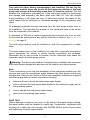
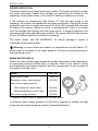
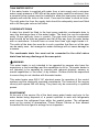
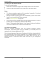
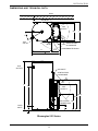
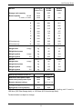
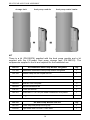
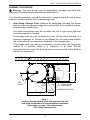
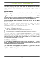
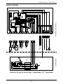
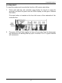
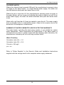
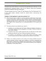
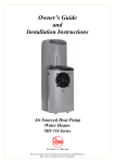
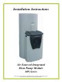
Installation Instructions Air Sourced Integrated Heat Pump Module MPi Series This water heater must be installed and serviced by a qualified person. Please leave this guide with the householder. PATENTS This water heater may be protected by one or more patents or registered designs in the name of Rheem Australia Pty Ltd. ® TRADE MARKS Registered trademark of Rheem Australia Pty Ltd. ™ Trademark of Rheem Australia Pty Ltd. Note: Every care has been taken to ensure accuracy in preparation of this publication. No liability can be accepted for any consequences, which may arise as a result of its application. CONTENTS HOUSEHOLDER – This installation instruction booklet is intended for the installer but you may find it of interest. Installation .............................................................................................. 4 Heat Pump And Tank Assembly ......................................................... 13 Connections – Electrical ..................................................................... 30 Commissioning .................................................................................... 32 Water Supplies ..................................................................................... 38 Warranty Note ...................................................................................... 40 3 INSTALLATION INSTALLATION STANDARDS The water heater must be installed: by a qualified person, and in accordance with the installation instructions, and in compliance with Standards AS/NZS 3500.4, AS/NZS 3000 and all local codes and regulatory authority requirements. In New Zealand, the installation must also conform with Clause G12 of the New Zealand Building Code. WATER HEATER APPLICATION This water heater is designed for use in a single family domestic dwelling for the purpose of heating potable water. Its use in an application other than this may shorten its life. If this water heater is to be used where an uninterrupted hot water supply is necessary for the application or business, then there should be redundancy within the hot water system design. This should ensure the continuity of hot water supply in the event that this water heater was to become inoperable for any reason. We recommend you provide advice to the system owner about their needs and building backup redundancy into the hot water supply system. This water heater is recommended for connection to a minimum 16 hour per day power supply for a 325 litre storage tank and a 24 hour per day power supply for a 410 litre storage tank. STORAGE TANK AND HEAT PUMP MODULE The heat pump water heater is made of two main components, the storage tank and the heat pump module. For transport and handling (weight) purposes both items are shipped separately and designed to be assembled at the installation site. The water heater must not be operated until both components are assembled. Refer to “Heat Pump and Tank Assembly” on page 13. Take care when handling the heat pump module. The jacket of the heat pump module needs to be handled gently so as not to cause damage. 4 INSTALLATION Care must be taken during transportation and handling. Do not lay the heat pump module down and do not tilt the heat pump module or the heat pump and storage tank assembly more than 30° from the vertical. This will displace the compressor lubricating oil. If the heat pump module or heat pump and storage tank assembly has been tilted more than 30° from the vertical during handling, it will need one hour to drain back before the power to the water heater can be switched on, otherwise damage to the compressor may result. All packaging materials must be removed from the heat pump module prior to its installation. This includes the removal of the cardboard base of the carton from the underside of the module. A clearance of 300 mm is required perpendicular from both the front air inlet louvres and the outlet grille to any wall or obstruction. Refer to the dimensions diagram on page 9. The heat pump module must be installed on and fully supported by a stable base. The water heater must not be installed in an area with a corrosive atmosphere where chemicals are stored or where aerosol propellants are released. Remember the air may be safe to breathe, but the chemicals may attack the materials used in the heat pump system. Warning: This heat pump module is designed to be installed with a purpose built water heater storage tank and may not be used for any other purpose. Note These instructions cover only the installation of the heat pump module onto the storage tank and the connections made between the heat pump module and storage tank. Refer to the Owner‟s Guide and Installation Instructions supplied with the storage tank for further information including: where and how to locate the heat pump water heater how to connect the heat pump water heater to the electricity supply and to the plumbing system how to operate the heat pump water heater what to do if something goes wrong. SAFE TRAY Where damage to property can occur in the event of the water heater leaking, the water heater must be installed in a safe tray. Construction, installation and draining of a safe tray must comply with AS/NZS 3500.4 and all local codes and regulatory authority requirements. 5 INSTALLATION FREEZE PROTECTION The water heater has a freeze protection system. The freeze protection system will protect the water heater from damage, by preventing ice forming in the waterways of the water heater, in the event of freezing conditions occurring. If the ambient air temperature falls below 1°C and the heat pump is not operating, the system will operate the circulator periodically. During this freeze protection cycle, the circulator will operate for thirty (30) seconds and then rest for fifteen (15) minutes, before the cycle is recommenced. Water is circulated from the storage tank through the heat pump circuit, to prevent freezing in the connecting pipe work and heat pump module. The green LED will flash a series of four (4) flashes whilst the circulator is operating. The water heater has NO WARRANTY for freeze damage if power is unavailable at the water heater. Warning: In areas where the ambient air temperature may fall below 1°C, power must be available to the water heater at all times to prevent freezing in the heat pump circuit. MAINS WATER SUPPLY Where the mains water supply pressure exceeds that shown in the table below, an approved pressure limiting valve is required. Refer to the Owner‟s Guide and Installation Instructions supplied with the storage tank for the position of the pressure limiting valve. Model 325, 410 Relief valve setting 1000 kPa Expansion control valve setting * 850 kPa Max. mains supply pressure With expansion control valve 680 kPa Without expansion control valve 800 kPa Min. mains supply pressure 200 kPa * Expansion control valve not supplied with the water heater. A minimum water supply pressure of 200 kPa is required to enable the heat pump circulator and heat pump system to operate effectively. 6 INSTALLATION TANK WATER SUPPLY If the water heater is supplied with water from a tank supply and a minimum water supply pressure of 200 kPa at the water heater cannot be achieved, then a pressure pump system must be installed to allow the heat pump circulator to operate and avoid air locks in the circuit. Care must be taken to avoid air locks. The cold water line from the supply tank should be adequately sized and fitted with a full flow gate valve or ball valve. CONDENSATE DRAIN A drain line should be fitted to the heat pump module‟s condensate drain to carry the discharge clear of the water heater. The drain line can be extended using 12 mm rigid poly hose or conduit. The pipe work from the condensate drain should be as short as possible and fall all the way from the water heater with no restrictions. It should have no more than three right angle bends in it. The outlet of the drain line must be in such a position that flow out of the pipe can be easily seen - but arranged so water discharge will not cause damage or nuisance. The condensate drain line must not be connected to the relief valves drain lines but may discharge at the same point. WARNING This water heater is only intended to be operated by persons who have the experience or the knowledge and the capabilities to do so. This water heater is not intended to be operated by persons with reduced physical, sensory or mental capabilities i.e. the infirm, or by children. Children should be supervised to ensure they do not interfere with the water heater. This water heater uses 240 V AC electrical power for operation of the control systems and the electrically operated components. The removal of the access cover(s) will expose 240 volt wiring. They must only be removed by a qualified person. ENVIRONMENT At the end of the service life of the heat pump water heater and prior to the water heater being disposed of, a person qualified to work with refrigerants must recover the refrigerant from within the sealed system. The refrigerant must not be vented to atmosphere. Phone Rheem Service or their nearest Accredited Service Agent to arrange for an inspection. 7 INSTALLATION TO TURN OFF THE WATER HEATER To turn off the water heater: Switch off the electrical supply at the isolating switch to the water heater. Close the cold water isolation valve at the inlet to the water heater. Notes The freeze protection system will be rendered inoperable if electrical power is not available at the water heater. Damage caused by freezing due to the unavailability of power at the water heater is not covered by the Rheem warranty. Refer to “Warranty Note” on page 40. If the power has been switched off to the water heater and there is a risk of freezing, then it is necessary to drain the water heater. Refer to “Draining the Water Heater” in the Owner‟s Guide and Installation Instructions supplied with the heat pump storage tank. VICTORIAN CUSTOMERS Notice to Victorian Customers from the Victorian Plumbing Industry Commission. This water heater must be installed by a licensed person as required by the Victorian Building Act 1993. Only a licensed person will give you a Compliance Certificate, showing that the work complies with all the relevant Standards. Only a licensed person will have insurance protecting their workmanship for 6 years. Make sure you use a licensed person to install this water heater and ask for your Compliance Certificate. 8 INSTALLATION DIMENSIONS AND TECHNICAL DATA WALL 100 AIR INLET AIR OUTLET 574 C 30 H 0M 0 TPR VALVE 30 IN N MI AIR INLET VENTILATION CLEARANCE CONDENSATE DRAIN 275 K B HOT OUTLET AIR INLET 30 0 M IN VENTILATION CLEARANCE A D AIR OUTLET 1018 872 ELECTRICAL 544 CONNECTION COLD INLET F E Rheemglas 551 Series HEAT PUMP DIMENSIONS 325 & 410 INTEGRATED 9 SK6753 - 1 A4 REV CD 04/13 INSTALLATION WALL 100 AIR INLET L AIR OUTLET 30 H 574 C 0M IN IN 0M 30 AIR INLET TPR VALVE VENTILATION CLEARANCE 275 K CONDENSATE DRAIN B M HOT OUTLET AIR INLET A 30 0 M IN VENTILATION CLEARANCE D AIR OUTLET 1018 872 ELECTRICAL CONNECTION 544 F COLD INLET E RheemPlusDIMENSIONS 554 Series HEAT PUMP 325 & 410 INTEGRATED SK6898-3 A4 REVCD 04/13 10 INSTALLATION Models Rheemglas RheemPlus 551325 554325 551410 554410 litres 325 410 Storage tank capacity Boost capacity 1.8 kW litres 100 - 2.4 kW*, 3.6 kW* litres 180 200 A mm 1631 1842 B mm 894 961 C mm 638 686 D mm 1317 1479 E mm 114 127 F mm 162 650 H deg 32 30 K mm 619 686 554 series only L mm 262 286 554 series only M mm 1006 1073 Rheemglas 551325 551410 kg 88 112 Dimensions Models Weight tank empty Weight heat pump kg 42 42 Weight system empty kg 130 154 Weight system full kg 455 564 RheemPlus 554325 554410 kg 90 112 Models Weight tank empty Weight heat pump kg 42 42 Weight system empty kg 132 154 Weight system full kg 455 564 Heat pump module model no 182550 (R) Maximum rated power input watts Rated heat pump power input watts 800 kW 1.8, 2.4, 3.6 Booster element ratings Refrigerant type Refrigerant circuit pressure 3600 R134a kPa 3000 * The boost capacity of a 2.4 kW or 3.6 kW low watts density heating unit if used is 100 litres (325 litre storage tank) or 125 litres (410 litre storage tank). Technical data is subject to change. 11 INSTALLATION TYPICAL INSTALLATION – OUTDOOR LOCATION Rheemglas 551 Series Shown TYPICAL INSTALLATION HEAT PUMP WATER HEATER - 325L 12 HEAT PUMP AND TANK ASSEMBLY STORAGE TANK AND HEAT PUMP MODULE The heat pump water heater is made of two main components, the storage tank and the heat pump module. For transport and handling (weight) purposes both items are shipped separately and designed to be assembled at the installation site. The water heater must not be operated until both components are assembled. The water heater is to be installed at ground or floor level and must stand vertically upright on a stable base, as acceptable to local authorities, of a minimum 900 mm wide x 650 mm deep. The heat pump module must be fully supported by the stable base. HEAT PUMP MODULE The heat pump module is shipped in a box containing two hand holes to facilitate easy handling and lifting. The heat pump module is to be mounted against the side of the storage tank. CAUTION: The heat pump module weighs approximately 42 kg. Use the hand holes provided in the sides of the packaging. Good lifting practice should be followed. There are two flexible hoses provided inside the heat pump module. The flexible hoses are to be withdrawn from the module and fixed to the two water fittings on the heat pump storage tank, during the assembly procedure. There are two connection points located on the underside of the control box in the heat pump module to which the power cable and tank sensor cable from the heat pump storage tank are connected, during the assembly procedure. STORAGE TANK The storage tank is designed to receive the heat pump module. There are two water fittings located at the side of the storage tank to which flexible hoses from the heat pump module are connected, during the assembly procedure. A power cable is housed behind the lower cover and a tank sensor cable is located adjacent to and above to the lower cover of the storage tank. The power cable is to be withdrawn from behind the front cover and the tank sensor cable unfurled and both connected to the control box in the heat pump module during the assembly procedure. 13 HEAT PUMP AND TANK ASSEMBLY storage tank heat pump module + heat pump water heater = KIT There is a kit (PN 299276) supplied with the heat pump module and a kit supplied with the 410 model heat pump storage tank (PN 290122). The components supplied in the kit and required for the installation are: 299276 Kit Installation Heat Pump Module Integrated Qty 122189 Installation instructions heat pump module integrated 1 052158 Saddle clamp 20 mm Clipsal 261/20 1 080021 Screw phillips pan head No. 8 x 13 zinc plated black 2 080156 Screw pack of 3 M6 x 12 HD bolts 2 080203 Stud M6 x 25 zinc plate 3 080204 Nut hex whizzlock M6 3 104767 Cover fan shroud 1 080191 Screw hilo 13-16 x 20 pan head combination zinc plated 1 104766 Plug plastic 13 mm black 1 290122 Kit Heat Pump Module Seal 410 Qty 087052 Cover strip heat pump housing top 1 160032 Tape foam 406E 18 mm x 7 mm thick 1 14 HEAT PUMP AND TANK ASSEMBLY ASSEMBLY PROCEDURE Warning: The heat pump must be assembled, plumbed and filled with water prior to power being connected and switched on. The following procedure should be followed to properly place the heat pump module in position and connect to the storage tank: 1. Heat Pump Storage Tank: Remove all packaging including the carton base from the heat pump storage tank and position in its intended location, supported by a stable base. The water connections may be on either the left or right hand side and should be parallel to the wall. The storage tank must be positioned at least 100 mm from the wall. If a minimum clearance of 100 mm is not allowed for, the heat pump module will not be able to be completely connected to the storage tank. The storage tank must also be positioned such that when the heat pump module is in position, there is a clearance of at least 300 mm perpendicular from both the front air inlet louvres and the outlet grille to any wall or obstruction. WALL 100 AIR INLET AIR OUTLET 574 30 0M H 0M TPR VALVE 30 IN IN AIR INLET VENTILATION CLEARANCE 275 K CONDENSATE DRAIN B HOT OUTLET Step 1 position storage tank at least 100 mm from the wall and allow for at least 300 mm ventilation clearance (refer table on page 11 for dimensions) 551 series shown above AIR INLET 15 VENTILATION CLEARANCE C HEAT PUMP AND TANK ASSEMBLY 2. Lower Front Cover: Remove the two screws securing the lower front cover to the storage tank. Remove the lower front cover from the storage tank. Step 2 remove screws from lower front cover 3. Step 3 withdraw the power cable Power Cable: Withdraw the power cable, housed behind the lower front cover, from the opening. 16 HEAT PUMP AND TANK ASSEMBLY 4. Mains Power Connection – 551 Series: Connect the mains power supply wiring to the terminal block and earth connection inside of the lower front cover. Secure the conduit to the side of the storage tank with the saddle clamp and screws provided. The saddle clamp must be positioned over the pilot holes provided, otherwise the conduit will interfere with the heat pump module installation. Refer to “Connections – Electrical” on page 30. Note: The power supply to the water heater must not be switched on until the installation is complete, the water heater is filled with water and a satisfactory megger reading is obtained. Step 4 Connect wiring and secure conduit with saddle clamp 17 HEAT PUMP AND TANK ASSEMBLY 5. Lower Front Cover: Refit the lower front cover. Step 5 refit lower front cover 6. Step 6 remove tape from tank sensor cable Tank Sensor Cable: Remove tape from tank sensor cable and unfurl. 18 HEAT PUMP AND TANK ASSEMBLY 7. Foam Tape: (410 litre storage tank only) – Retrieve the length of foam tape from the kit supplied with the 410 storage tank. The foam tape is to be applied to the bottom at the front of the 410 litre storage tank. The ends of the foam tape are to line up with the two vertical slots in the jacket. The mid point of the tape (lengthways) is to line up over the join between the jacket of the storage tank and the jacket bottom. Remove the backing from the foam tape and apply the foam tape to the storage tank. FOAM TAPE REMOVE ADHESIVE PAPER BACKING LINE UP EDGES OF FOAM TAPE UNDER SLOTS. MID POINT OF FOAM TAPE TO LINE UP OVER JOIN BETWEEN JACKET AND JACKET BOTTOM. FOAM TAPE APPLICATION HEAT PUMP INTEGRATED 410 LITRES Step 7 apply foam tape to 410 litre storage tank 8. Heat Pump Module: Remove all packaging including the carton base from the heat pump module and position in its intended location at the storage tank. SK6570-2 REV BD 30/4/13 CAUTION: The heat pump module weighs approximately 42 kg. Use the hand holes provided in the sides of the packaging. Good lifting practice should be followed. 19 HEAT PUMP AND TANK ASSEMBLY 9. Fan Cover Shroud: Retrieve the fan cover shroud, 20 mm screw and black plastic plug from the kit bag. Remove the screw located immediately above the monitor label on the front of the heat pump module and discard. Position the fan cover shroud over the fan cowl and slide the recessed edge of the shroud under the lip of the heat pump module top. It will slide under the top without having to remove any screws. Align the mounting hole at the bottom of the shroud with the screw hole in the heat pump module located immediately above the monitor label. Secure the fan cover shroud to the heat pump module with the 20 mm screw provided. Insert the black plug provided into the recess to cover the head of the screw. REMOVE AND DISCARD EXISTING SCREW FAN COVER SHROUD SCREW PLUG Step 9 fit the fan cover shroud to the heat pump module 20 HEAT PUMP AND TANK ASSEMBLY 10. Cover Strip: (410 litre storage tank only) – Retrieve the length of rubber cover strip from the kit supplied with the 410 storage tank. Line up one end of the cover strip with one end of the heat pump housing black top, fitting the strip over the lip of the housing, ensuring the jacket is hard up against the lip of the heat pump housing. The cover strip will hold the jacket in position. Apply the cover strip along the full length of the lip of the heat pump housing. COVER STRIP ASSEMBLY DETAIL HEAT PUMP HOUSING COVER STRIP COVER STRIP HEAT PUMP HOUSING COVER STRIP APPLICATION HEAT PUMP INTEGRATED 410 LITRE Step 10 apply cover strip to heat pump housing 21 SK6570-1 rev BD 1/5/13 HEAT PUMP AND TANK ASSEMBLY 11. Heat Pump Module Cover: Remove the two screws securing the front cover to the heat pump module. Remove the front cover from the heat pump module. Step 11 and 13 remove front cover from heat pump module and feed through cables 12. Position Heat Pump Module: Position the edge of the heat pump module which is closest to the wall against the storage tank so the screw holes in the module are adjacent to the nutserts in the storage tank. 13. Power Cable and Tank Sensor Cable: Feed the power cable from the lower front cover and tank sensor cable through the heat pump module so they protrude out of the front of the module. 14. Flexible Braided Hoses: Retrieve the loose ends of the two flexible braided hoses from within the heat pump module, and withdraw through the rear of the heat pump module. 22 HEAT PUMP AND TANK ASSEMBLY 15. Cold Hose Connection: Attach the flexible braided hose, marked with a blue stripe through the braid and attached to the bottom of the heat exchanger, to the ball valve fitting in the bottom connection on the storage tank and marked “TO HEAT PUMP”. Tighten the swivel nut on the hose using a 24 mm spanner. Tape or sealant is not required. Position the hose such that when the heat pump module is moved and secured to the tank, it does not kink. Ball valve: Ensure the ball valve located in the connection fitting is in the open position. In the open position, the slot is in line with the hose. Step 15 attach flexible hose with blue stripe to inlet and ball valve in open position 23 HEAT PUMP AND TANK ASSEMBLY 16. Hot Hose Connection: Attach the flexible braided hose, marked with a red stripe through the braid and attached to the top of the circulator, to the non return valve fitting in the upper connection marked “OUTLET” in red on the storage tank. Tighten the swivel nut on the hose using a 24 mm spanner. Tape or sealant is not required. Position the hose such that when the heat pump module is moved and secured to the tank, it does not kink. Step 16 attach flexible hose with red stripe to outlet 17. Check Hoses: Check to ensure the flexible hoses are not kinked. 24 HEAT PUMP AND TANK ASSEMBLY 18. Cable Tab – 551 Series: Remove the tab on the side of the electrical entry to the heat pump module to accommodate the electrical conduit. Pliers or tin snips may be required to remove the tab. Step 18 remove the tab on the side of the electrical entry to the heat pump module 19. Studs: Retrieve the three (3) studs from the kit and screw into the three (3) threaded inserts on the side of the tank closest to the wall. These studs will assist in aligning the heat pump module for connection to the storage tank. Step 19 screw in studs into threaded inserts 25 HEAT PUMP AND TANK ASSEMBLY 20. Position Heat Pump Module: Position the heat pump module against the tank. Engage the tab at the bottom of the heat pump module, on the wall side of the module, into the slot in the tank. Align the holes in the side of the heat pump module over the three studs. 21. Flange Nuts: Screw the three flange nuts onto the studs to connect the wall side of the heat pump module to the storage tank. Steps 20 and 21 align heat pump module over studs and screw on flange nuts 22. Tab: Engage the tab at the bottom of the heat pump module, on the front side of the module, into the slot in the tank. 23. Fixing Bolts: Screw in the three fixing bolts to connect the front side of the heat pump module to the storage tank. Step 23 screw in fixing bolts to connect heat pump module to storage tank 26 HEAT PUMP AND TANK ASSEMBLY 24. Tank Sensor Cable Connection: Insert the tank sensor cable plug to the connector on the underside of the control box. The plug is polarised and can only be inserted one way. Ensure the plug fully engages the locking feature on the connector. 25. Power Cable Connection: Insert the four pin power cable plug to the connector on the underside of the control box. The plug is polarised and can only be inserted one way. Steps 24 and 25 connect power cable and tank sensor cable 27 HEAT PUMP AND TANK ASSEMBLY 26. Positioning of Water Heater: Complete final positioning of the water heater. Ensure the heat pump module is firmly seated on the level slab or solid base. 27. Water Connections: Connect the cold water supply and the hot water pipe work to the water heater. Connect the temperature pressure relief valve and its drain line. Refer to “Connections – Plumbing” in the Owner‟s Guide and Installation Instructions supplied with the storage tank. 28. Water Supply: Turn on the cold water supply and fill the water heater. Check the pipe work and the connection points for the flexible braided hoses for leaks Refer to “To Fill And Turn On The Water Heater” on page 32, however the electrical supply should not be turned on at this stage. 29. Heat Pump Module Cover: Replace the heat pump module cover and refit the two screws. Step 29 replace heat pump module front cover 28 HEAT PUMP AND TANK ASSEMBLY 30. Electrical Cover – 554 Series: Remove the two screws securing the electrical cover, adjacent to the temperature limiting valve cover, to the storage tank. Remove the electrical cover from the storage tank. Step 30 remove screws from electrical cover 31. Mains Power Connection – 554 Series: Connect the mains power supply wiring to the terminal block and earth connection inside of the electrical cover. Secure the conduit to the side of the storage tank with the saddle clamp and screws provided. Refer to “Connections – Electrical” on page 30. Note: The power supply to the water heater must not be switched on until the installation is complete, the water heater is filled with water and a satisfactory megger reading is obtained. Step 31 connect wiring to terminal block Step 32 refit electrical front cover 32. Electrical Cover – 554 Series: Refit the electrical cover. 33. Commissioning: Refer to “Commissioning” in the Owner‟s Guide and Installation Instructions supplied with the storage tank. 29 CONNECTIONS – ELECTRICAL The power supply to the water heater must not be switched on until the water heater is filled with water and a satisfactory megger reading is obtained. MEGGER READING When a megger test is conducted on this water heater, then the following should be noted. Warning: This water heater contains electronic equipment and 500 V insulation tests must only be conducted between active and earth and between neutral and earth. An active to neutral test WILL damage the electronics. An insulation test result of between 100 KΩ and 660 KΩ for this water heater is normal. Typically the insulation resistance between live and earthed parts of an electrical installation should not be less than 1 MΩ. However AS/NZS 3000:2000 clause 6.3.3.3.2 „Results‟ states: “The value of 1 MΩ may be reduced to: 0.01 MΩ for sheathed heating elements or appliances; or a value permitted in the Standard applicable to electrical equipment.” This model water heater is categorised as a „stationary class 1 motor operated appliance‟ and has been tested to AS/NZS 3350.1:2002 clause 16 „Leakage current and electric strength‟ and has passed the requirements of this Standard. Therefore, this model water heater complies with the condition stated in AS/NZS 3000:2000 clause 6.3.3.3.2 (b). ELECTRICAL CONNECTION All electrical work and permanent wiring must be carried out by a qualified person and in accordance with the Wiring Rules AS/NZS 3000 and all local codes and regulatory authority requirements. This water heater is recommended for connection to a minimum 16 hour per day power supply for a 325 litre storage tank and a 24 hour per day power supply for a 410 litre storage tank. 30 BROWN A BLACK N Electrical Circuit for Heat Pump – Robertshaw “ST” Thermostat 31 TANK THERMOSTAT HEATER ELEMENT CABLING IN CONDUIT INSIDE TANK JACKET LIGHT RED TANK ASSEMBLY E LIGHT RED BLUE GREEN/YELLOW LOWER TANK THERMISTOR (T0) R COMPRESSOR THERMISTOR BLACK BLACK EVAPORATOR THERMISTOR BLACK BLACK LED M 4 1 2 3 POWER PLUG CONDENSER THERMISTOR CABLE SET M 1 3 2 FAN PLUG M 1 3 4 2 PUMP PLUG GREEN/YELLOW BLUE RED GREEN/YELLOW BLUE BROWN BLACK 1 2 3 RED BLUE YELLOW BLACK M 1 2 3 F 1 2 F F 1 2 3 M 1 2 M BLACK BLUE BLACK YELLOW GREEN GREEN RED RED GREY GREY BLACK BLACK GREEN/YELLOW BLUE RED WHITE GREEN/YELLOW BLUE RED GREEN/YELLOW BLACK BLUE RED GREEN/YELLOW RED RED RED COMPRESSOR CAPACITOR CONTROL BOARD ENCLOSURE FAN CAPACITOR HEATER MODULE ASSEMBLY Push button M 1 2 3 1 2 F 1 2 1 2 3 M 1 2 3 F F RED BLACK WHITE 1 2 3 4 F 4 1 2 3 F 1 3 2 F 1 3 4 2 F 1 3 4 2 M 1 3 4 2 COMPRESSOR PLUG GREEN/YELLOW BLACK BLUE RED GREEN/YELLOW BLUE RED WHITE PUMP FAN COMPRESSOR S C F 1 2 M 1 2 BLACK HP SW HP SW PLUG BLUE GREEN/YELLOW NEUTRAL FAN-A 1 2 1 NO COM COIL LED 1 T1 - EVAP T2 - COMP T0 - TANK T3 - ELMT NC CONTROL BOARD 3 serial port EARTH PUMP-N PUMP-A FAN-N COMP-N COMP-A 4 NO COM NC 5 1 C B A CONNECTIONS – ELECTRICAL WIRING DIAGRAM PROG COMMISSIONING TO FILL AND TURN ON THE WATER HEATER The power supply to the water heater must not be switched on until the water heater is filled with water and a satisfactory megger reading is obtained. Open all of the hot water taps in the house (don‟t forget the shower). Open the cold water isolation valve fully to the water heater. Air will be forced out of the taps. Close each tap as water flows freely from it. Check the pipe work and the connection points for the flexible braided hoses for leaks Switch on the electrical supply at the isolating switch to the water heater. Set the timer if one is installed. If it is necessary to adjust the outlet temperature of a RheemPlus model, refer to “Outlet Temperature Compensation Adjustment – RheemPlus” in the Owner‟s Guide and Installation Instructions supplied with the heat pump storage tank. Note: The water heater is preset in the factory to allow it to commence operating with either the heat pump or booster heating unit immediately power is turned on for the first time. If power is turned on and then off at its installation, the water heater may take up to forty five (45) minutes to commence operating when the power supply is switched on again. This forty five (45) minute period can be overridden during the commissioning procedure if the power was inadvertently turned on and then off again. Refer to “System Reset” on page 37. The heat pump will only operate when power is available at the water heater, the water in the storage tank requires heating, the heat pump compressor is cool and the ambient air temperature is within the heat pump‟s operating temperature range of between a minimum of 3°C to 5°C and a maximum of 45°C to 55°C. If the ambient temperature is outside of this range, the water heater will commence heating with the booster heating unit. When the heat pump is operating, the system will switch to the booster heating unit if the detected ambient air temperature is outside the operating temperature range of between a minimum of 3°C to 5°C and a maximum of 45°C to 55°C. 32 COMMISSIONING The system will not switch back to heat pump operation from the booster heating unit if the detected ambient air temperature has moved back within the heat pump‟s operating temperature range. The heating cycle will be completed by the booster heating unit. Note: The heat pump may not turn on after either having just completed a heating cycle and more hot water is drawn from the water heater or power is shut down to the compressor, either during or at the end of a heating cycle. The heat pump will wait until the compressor has cooled down and the conditions for start up are favourable in order to protect the compressor from damage. This will be a minimum of forty five (45) minutes and may take up to ninety (90) minutes from the last heating cycle. It is important to wait for five (5) minutes after the heat pump has activated to ensure it continues to operate and is functioning correctly. Explain to the householder or a responsible officer the functions and operation of the heat pump water heater. Upon completion of the installation and commissioning of the water heating system, leave this guide with the householder or a responsible officer. TO TURN OFF THE WATER HEATER Refer to “To Turn Off the Water Heater” on page 8. DIAGNOSTIC FEATURES OF THE HEAT PUMP CONTROLLER An operating mode monitor is located on the front of the heat pump module and houses a green and a red LED. The green LED, marked “NORMAL”, indicates the current operating mode (with the red LED off) of the heat pump water heater and the red LED, marked “ATTENTION”, may indicate a potential fault mode. The green LED will emit either a constant glow or a series of flashes, with a 2 second interval between each series. A series of long green flashes may also be emitted. The red LED will emit either a solid glow or a series of flashes, with a 2 second interval between each series. A series of flashes indicates there may be a particular fault condition with the system. 33 COMMISSIONING The modes are: Flashes solid green (remains on) Operational Modes Standby mode – water is hot 1 x green Call for heating received – system checks performed Note: unit may wait and continue flashing until compressor has cooled from its last operation 2 x green Heat pump preheating 3 x green Heat pump operation – compressor and fan running 4 x green Freeze protection operation – circulator on long green Heating unit on – ambient air temperature below 3°C to 5°C or above 45°C to 55°C rapid green System start up – heating unit on no green (remains off) No power at the water heater or to the heat pump or a possible fault condition Refer to notes overleaf before calling for service Flashes Indicator or Fault Modes 1 x red Heating unit on compressor over temperature (possible circulator fault) 3 x red Heating unit on compressor cooling fault condition 4 x red Heating unit on tank thermistor fault condition 5 x red Heating unit on evaporator thermistor fault condition 6 x red Heating unit on compressor thermistor fault condition 7 x red Heating unit on heat exchanger water outlet sensor fault 8 x red Heating unit on water flow fault condition 9 x red Heating unit off refrigeration system (compressor) fault condition Call for service solid red (remains on) + solid green (remains on) Heating unit off system reset – release button 34 COMMISSIONING Notes: There is no 2 x red flash indicator or fault mode code. Power must be available at the water heater and to the heat pump for the LEDs to glow or flash. Time controlled power supply (power must be available at the water heater) If the water heater is connected to a time controlled power supply, then during periods of no power supply at the water heater the LEDs will be off. This is not a fault condition, but a result of no power being available to energise the LEDs. The green LED will recommence glowing or flashing when power is available again at the water heater. Heat pump operating range (power must be available to the heat pump) The heat pump‟s operating range is between an ambient air temperature of a minimum of 3°C to 5°C and a maximum of 45°C to 55°C. The heat pump will not operate when the ambient air temperature is outside the heat pump‟s operating range. If heating is required, the water heater will commence heating with the booster heating unit in booster heating mode (long green flash) instead. The water will be heated to 70°C during these periods. At the completion of this heating cycle by the booster heating unit (long green flash), the thermostat controlling the booster heating unit opens circuit cutting power to the heat pump causing the green LED to go out. This is not a fault condition, but a result of the power being cut to the heat pump by the thermostat. Refer to “Heat pump operating range” in the “Save A Service Call” section of the Owner‟s Guide and Installation Instructions supplied with the heat pump storage tank for further explanation. 35 COMMISSIONING Possible fault condition If there is power to the water heater and the green LED is off or the red LED is flashing, this indicates there may be a fault condition with the water heater. The red LED may emit up to nine flashes in each series of flashes. There may be a fault condition with the water heater if either: there is power available at the water heater and the green LED is off, and the water heater has not operated outside of the heat pump‟s operating range. Before phoning to arrange a service inspection due to the green LED being off, refer to “Heat Pump Is Not Operating” in the “Save A Service Call” section of the Owner‟s Guide and Installation Instructions supplied with the heat pump storage tank. or the red LED is flashing – the red LED may emit up to nine flashes in each series of flashes The fault condition which led to the red LED flashing may be cleared after the backup heating cycle by the booster heating unit has completed. When heating is next required the red LED will recommence to flash the fault code for 27 seconds and then extinguish. If the red LED then recommences to flash or recommences to flash after the heat pump next operates, a service call may be required. Before phoning to arrange a service inspection due to the red LED flashing, refer to “Heat Pump Is Not Operating” in the “Save A Service Call” section of the Owner‟s Guide and Installation Instructions supplied with the heat pump storage tank. 36 COMMISSIONING SYSTEM RESET To reset the system and override the forty five (45) minute start delay: 1. Press and hold the red controller reset button for two (2) to three (3) seconds until both the green and red LEDs display a solid glow. Release the button. The reset button is located on the front left corner of the underside of the controller box. reset button 2. The green LED will flash rapidly for three (3) seconds, then the heat pump will commence its heating start-up cycle. A series of 2 or 3 x green flashes will commence. 37 WATER SUPPLIES This water heater must be installed in accordance with this advice to be covered by the manufacturer’s warranty. This water heater is manufactured to suit the water conditions of most public reticulated water supplies. However, there are some known water chemistries which can have detrimental effects on the water heater and its operation and / or life expectancy. If you are unsure of your water chemistry, you may be able to obtain information from your local water supply authority. This water heater should only be connected to a water supply which complies with these guidelines for the manufacturer‟s warranty to apply. CHANGE OF WATER SUPPLY The changing or alternating from one water supply to another can have a detrimental effect on the operation and / or life expectation of a number of components in this water heater. Where there is a changeover from one water supply to another, e.g. a rainwater tank supply, bore water supply, desalinated water supply, public reticulated water supply or water brought in from another supply, then water chemistry information should be sought from the supplier or it should be tested to ensure the water supply meets the requirements given in these guidelines for the manufacturer‟s warranty to apply. SATURATION INDEX The saturation index (SI) is used as a measure of the water‟s corrosive or scaling properties. Where the saturation index is less than –1.0, the water is very corrosive and the manufacturer‟s warranty does not apply to the water heater. In a corrosive water supply, the water can attack copper parts and cause them to fail. Where the saturation index exceeds +0.40, the water is very scaling and the manufacturer‟s warranty does not apply to the water heater. Water which is scaling may be treated with a water softening device to reduce the saturation index of the water. 38 WATER SUPPLIES CHLORIDE AND PH Where the chloride level exceeds 250 mg/L the manufacturer‟s warranty does not apply to the water heater. In a high chloride water supply, the water can corrode stainless steel parts and cause them to fail. Where the pH is less than 6.0 the manufacturer‟s warranty does not apply to the water heater. pH is a measure of whether the water is alkaline or acid. In an acidic water supply, the water can attack stainless steel parts and cause them to fail. Water with a pH less than 6.0 may be treated to raise the pH. The water supply from a rainwater tank in a metropolitan area is likely to be corrosive due to the dissolution of atmospheric contaminants. SUMMARY OF WATER CHEMISTRY ADVICE AFFECTING WARRANTY The water heater, including this heat pump module, is not suitable for certain water chemistries. Those chemistries are listed below. If the water heater is connected at any time to a water supply with the following water chemistry, the manufacturer‟s warranty will not cover any resultant faults: Water Chemistry Saturation Index (SI) < -1.0 Saturation Index (SI) > +0.4 Chloride > 250 mg/L pH < 6.0 Refer to “Water Supplies” in the Owner‟s Guide and Installation Instructions supplied with the storage tank for the complete water supply statement. 39 WARRANTY NOTE The heat pump water heater is covered by the manufacturer‟s warranty. For full manufacturer‟s warranty details, refer to the Owner‟s Guide and Installation Instructions supplied with the storage tank. The part extracts from the “Terms Of The Warranty And The Exclusions To It” of the water heater warranty should be noted before commencing the installation. TERMS OF THE WARRANTY AND EXCLUSIONS TO IT 2.5 Where the water heater is installed in a position that does not allow safe or ready access, the cost of that access, including the cost of additional materials handling and/or safety equipment, shall be the owner’s responsibility. In other words, the cost of dismantling or removing cupboards, doors or walls and the cost of any special equipment to bring the water heater to floor or ground level or to a serviceable position is not covered by this warranty. 2.7 The warranty does not cover faults that are a result of: c) Installation not in accordance with the Owner’s Guide and Installation Instructions or with relevant statutory and local requirements in the State or Territory in which the water heater is installed. d) Connection at any time to a water supply that does not comply with the water supply guidelines as outlined in the Owner’s Guide and Installation Instructions. k) Ice formation in the waterways of a water heater system incorporating a freeze protection system where the electricity supply has been switched off or has failed. 2.8 Subject to any statutory provisions to the contrary, this warranty excludes any and all claims for damage to furniture, carpet, walls, foundations or any other consequential loss either directly or indirectly due to leakage from the water heater, or due to leakage from fittings and/ or pipe work of metal, plastic or other materials caused by water temperature, workmanship or other modes of failure. Revision Date: 2014 July 122189B 40