1
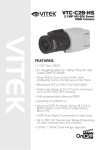
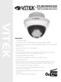
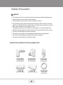
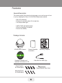
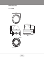
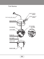
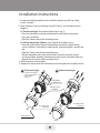
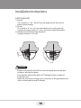
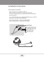
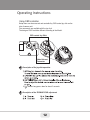
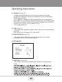
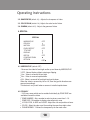
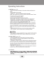
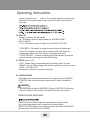
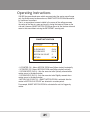
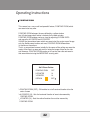
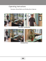
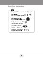
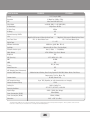
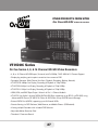
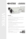
VTC-HOCRAZ39/922
2.1MP HD-SDI Compact Indoor/Outdoor
WDR True Day/Night Dome Camera
VITEK
FEATURES:
• 1/2.9” Sony® CMOS
• 2.1 MegaPixel With full 1080p/720p HD-SDI Output (SMPTE 292M)
• MegaPixel IR Corrected 3-9mm (VTC-HOCRAZ39) /9-22mm (VTC-HOCRAZ922)
Varifocal Lens
• Mechanical IR Cut Filter (True Day/Night)
• 16:9 Video format
• On-board Intelligence (OBI Technology) delivers Auto-Focus-Zoom by tracking
motion, then optically zooming in to that area of the frame
• Fully programmable advanced WDR
• Two (2) High Power 850nm IR LEDs with up to 80’ foot range
• Integrated Cooling Fan
• Advanced OSD Functions: Motion Activated Pointing Zoom, Defog, Dynamic IR,
BLC/HLC, Motion Deblur, Pixel Defect Compensation, Title Set, Mirror, Flip
• 100% Pure Digital Transmission of video data
• Up to 700’ HD Transmission Range (Depending on cable
characteristics and integrity)
• Heavy Duty IP68 rated weather/vandal resistant aluminum
construction
• 12VDC / 24VAC Dual Voltage Operation
Safety Precaution
To prevent fire or shock hazard, do not expose the unit to rain or moisture.
To prevent electric shocks and risk of fire hazards, do NOT use other than
specific power source.
CAUTION: TO REDUCE THE RISK OF ELECTRIC SHOCK,
DO NOT REMOVE COVER (OR BACK).
NO USER SERVICEABLE PARTS INSIDE.
REFER SERVICING TO QUALIFIED SERVICE PERSONNEL.
The symbol is intended to alert the user to the presence of uninsulated
"dangerous voltage" within the product’s enclosure that may be of
sufficient magnitude to constitute a risk of electric shock to persons .
The symbol is intended to alert the user to the presence of important
operating and maintenance(servicing) instructions in the literature
accompanying the unit.
Warning :
This equipment has been tested and found to comply with the limits for a Class
A digital device, pursuant to part 15 of the FCC Rules. These limits are designed
to provide reasonable protection against harmful interference when the equipment
is operated in a commercial environment . This equipment generates, uses, and
can radiate radio frequency energy and, if not installed and used in accordance with
the instruction manual, may cause harmful interference to radio communications.
Operation of this equipment in a residential area is likely to cause harmful
interference in which case the user will be required to correct the interference at
his own expense.
Caution :
Any changes or modifications in construction of this device which are not expressly
approved by the party responsible for compliance could void the user’s authority
to operate the equipment.
Mains power quality should be that of a typical commercial environment. If the user
of the model requires continued operation during power mains interruptions, it is
recommended that the model be powered from an uninterruptible power supply
(UPS) or a battery.
2
Safety Precaution
NOTICE
The image used in this instruction manual are processed to help comprehension
and may differ from actual video of the camera.
Avoid installing in areas where shock or vibration may occur.
Pay attention to safety when installing the connection cable and observe that the
cable is not subjected to heavy leads, kinks or damage and no moisture can get in.
Never open the device such as boards or lens.
The warranty becomes void if repairs are undertaken by unauthorized persons.
Maintenance and repair have to be carried out only by authorized service centers.
Use only a mild detergent to clean the housing.
The camera should never be operated beyond the technical specifications.
This can lead to damage to the camera and void the warranty.
The camera should never be operated in water.
Optional Dome Mounts to Suit any Application!
3
Contents
p. 02 - 03
Safety Precaution
Optional Dome Mounts
p. 04
Contents
p. 05 - 06
Features
p. 02- 03
Package Includes
p. 07
Dimensions
p. 09
Part Names
p. 09 - 11
Installation Instructions
p. 12 - 25
Operating Instructions
p. 26
Specifications
p. 28
Warranty
4
Features
Key Features
¥ Full HD, 2Mega Pixel HD-SDI CAMERA, 1920x1080(30p/25p)
¥ True WDR(Wide Dynamic Range)
Improved Noise reduction with the enhanced 3D-NR
¥ VTD-HOCRAZ39: f=3~9mm, F1.2~F2.1 Day&Night zoom lens
(Optical 3x Auto focus zoom / Digital 32x zoom)
VTD-HOCRAZ922: f=9~22mm, F1.6~F2.3 Day&Night zoom lens
(Optical 2.4x Auto focus zoom / Digital 32x zoom)
¥ Focusing Status Indicator on Screen
- ★(Blue) Focusing in process
- ★(White) Focusing Completed
Dual Filter Switching
M.A.P. - Motion Activated Pointing Zoom which enables the flexible zooming at any area.
¥ Smart Motion Zoom in combining with Pointing Zoom.
Selectable Scale down image to 720p mode
¥ Motion Detect, Privacy Mask, Defog, Sens-up(x32), BLC/HLC, HV Flip,
D-Zoom(1.1x~8x), LSC(Lens Shade Compensation), Motion Deblur
Pixel Compensation
¥ ID / TITLE / ZOOM RATIO DISPLAY
Enhanced light Sensitivity by DSS technology
¥
¥
¥
¥
¥
¥
¥
¥
¥
¥
¥
Top performance at low light sensitivity (Sens-up On)
OSD menu & Video sub-out for easy installation & maintenance.
Circuit protection against faulty connection in power polarity
Isolated power supply against ground loop problem
Remote control via RS-485 (Pelco-D/P)
2 High power LEDs
Flush / Surface mount selectable
Hard Coated Polycarbonate Clear bubble dome
Built-in 3-Axis Gimbal
Built-in cooling Fan & Heating function
IP68 / IK10 Protection
5
Features
General Description
This camera realizes the natural and crisp image as you see the scene in front
of you by adopting Auto Focus Full HD(1920x1080p) camera module.
• With ICR mechanism,
- Enhances its sensitivity about 10x at night time
- Can Accept Infared light
• 24VAC/12VDC dual power design,
- Offers the flexibility of Installation
- Ensures the reliability
Package Includes
HD-SDI Dome Camera
General Operation
Instructions
Complete Installation and
Operation Instructions on CD
Mounting Template
Video Sub-Out Cable (1pc)
Plastic Anchor:
6 x 30mm (4pcs)
Torque Wrench: 3mm (1pc)
Mounting Screw:
4 x 30mm (4pcs)
6
Dimensions
(unit: inches)
5.5
4.7
4.7
3.2
3.9
2.7
1.5
See Optional Dome Mounts
(pg. 3)
4.0
5.5
PCD 4.7
3-0.17
7
Part Names
CONDUIT SPACER
(Option)
CONDUIT HOLE CAP
POWER AND VIDEO CABLE
(Option)
SURFACE MOUNT
(Option)
OSD CONTROL
JOY STICK
FLUSH MOUNT
3-AXIS GIMBAL
ZOOM LENS
SAFTY WIRE
DOME COVER
BUBBLE DOME
8
Installation Instructions
1. Locate the mounting template at the installation position and drill the ceiling
or wall if needed.
3
2. Open the dome cover by loosening screws(4x12mm).
Use the torque wrench
supplied.
A. Flush mount type: See Optional Dome Mounts (pg. 3)
- Place the dome base unit on pre-drilled position and attach using mount.
ing screws (4x30mm).
- Route the Power cable to the connecting place.
B. Surface mount type (Option): See Optional Dome Mounts (pg. 3)
- Place the surface mount on pre-drilled position and attach using mounting
screws (4x30mm). Assemble the cable conduit, otherwise tighten a conduit hole
.
cap.
- Route the Power cable to the connecting place.
- Affix the dome base unit to the surface mount using the assembly screws
(4x14mm). Before attaching the dome base make sure the assembly holes are
aligned with the surface mount assembly holes.
4. Set the cameras viewing angle.
5. Replace the dome cover to the dome base unit and tighten the assembly screws.
Flush
mount
type
mount
type
AAFlush
Surface
mount
type
mount
type
BBSurface
Flush Mount Installation
Flush
Mount
Installation
requires
a Flush
Mount
Decorator
Plate Mount
requires
a Flush
(See pg. 3)
Decorator Plate (See
pg. 3)
Flush Mount
Decorator Plate
Mounting Screw
Mounting
Screw
(4x30mm)
(4x30mm)
Assembly Screw
Assembly(4x14mm)
Screw
(4x14mm)
Assembly Screw
Assembly(4x12mm)
Screw
(4x12mm)
Torque Wrench
Torque Wrench
9
Installation Instructions
Limit of pan & tilt
1) Pan limit:
Pan is limited to +/- 165°. Do NOT force the gimbal over the limit, this will
prevent internal damage.
2) Tilt limit:
Tilt is limited to 15° min ~ 90° max. with reference to the ceiling when the
inclination of camera module is 0°, that is, the image is aligned horizontally.
3) Inclination limit (Horizontal image alignment):
Inclination limited to +/-60° max.
15…
…
90
CAUTION
• Extreme care should be taken NOT to scratch the bubble dome surface while
installing or adjusting the camera.
• Care should be taken that the cable is NOT damaged, kinked or exposed in
a hazardous area.
• Tighten the dome cover mounting screws so that there is NO gap between Lens
hood and clear bubble to avoid IR reflection
.
10
Installation Instructions
Power Supply Connections
Make sure the power is removed before installation.
Camera can work with either 24VAC or 12VDC, dual voltage power..
Primary and secondary grounds are completely isolated to avoid the possible
ground-loop problems.
In case that HD-SDI Inputs are not supported by Monitor, please use HD-S DI
Converter to connect HD-SDI cable with Monitor
Some computer monitors or TVs may not support 30p/25p.
Please check Specification of Monitor before installation.
VIDEO (BNC)
AC24V/DC12V (Red wire)
AC24V/GND (Black wire)
RTX+ (White wire)
RTX- (Gray wire)
0.2M
11
Operating Instructions
Using OSD controller
Setup menu can be accessed and controlled by OSD control joy stick on the
side of camera unit.
Five commands are available with the joy stick.
The design of OSD could be different according to the Model.
OSD control Joy Stick
Video Sub-out
Connector
Description of the joystick operation
4)
denotes long press down for about 2 seconds
Description of the ZOOM&FOCUS adjustment
12
Operating Instructions
OSD menu Start up
Press ☟’(OSD menu SET key) down to access the setup menu mode.
Lens Initializing is strongly recommended at the first stage of setup menu control.
ZOOM/FOCUS > LENS INIT > Press the joystick ☟’straight down for about
2 seconds.
MENU
1. ZOOM/FOCUS
2. EXPOSURE
3. SCENE ENHANCE
4. 3D-NR
5. DAY/NIGHT
6. PICT ADJUST
7. SPECIAL
8. SYSTEM
9. EXIT
V3.12
NORMAL
MID
EXT
SAVE&EXIT
Direct Control menu
MAIN
DEFAULT
DESCRIPTION
ZOOM/FOCUS
-
Sets FOCUS MODE, D-ZOOM, LENS REFRESH and LENS INIT
EXPOSURE
-
Sets EXPOSURE MODE, BRIGHTNESS, SENS-UP, AGC and
MOTION DEBLUR.
SCENE
ENHANCE
NORMAL SCENE ENHANCE provides several ways to enhance the video
in various environments with the settings in NORMAL, WDR,
D-WDR, BLC and HLC.
NORMAL
Optimized for normal indoor and outdoor in good
lighting condition.
WDR
Improves the visibility for bright areas and dark
areas by double capture of image with LONG and SHORT
exposures. With WDR ON, the frame rate becomes half by the double
capture. WDR level can be selected from LOW, MID and HIGH. .
Care should be taken to select this mode because video may lose
its quality in some environments by over compensation.
※ CVBS video signal: Connecting 2nd video to CVBS port disables
WDR function temporarily. It should be considered when installer
adjusts the video with installation monitor via CVBS video signal.
D-WDR
Improves the visibility by compensating the video gain for
the dark area. Noise can increase in the dark area accordingly.
13
Operating Instructions
SCENE
ENHANCE
3D-NRM
DAY/NIGHT
NORMAL
ID
EXT
for
IR LED
AUTO
for
No IR
LED
BLC — Improves the visibility of dark objects caused by bright back
light. Outside area of BLC window can over saturate.
BLC has a target window for compensation and its size and position
can be set by H-POS, V-POS, H-SIZE and V-SIZE. .
HLC — Cuts out the highlight area with a black mask and excludes it
from compensation. Lower HLC LEVEL the more sensitive it is to
bright light.
3D-NR is a very sophisticated and powerful time-based noise
reduction technology by monitoring the noise for the several video
frames and defining and eliminating them consecutively at low light. .
Higher setting reduces noise more but results in losing the sharpness and tail effects or motion blur may occur.
.
Sets DAY / NIGHT to EXT, AUTO, COLOR or B/W.
SMART IR can be set to reduce saturation by strong IR
illumination at night in any menu of EXT, AUTO and B/W(NIGHT)
Setting SMART IR in any menu is identically applied to other menu.
Zero(0) turns off SMART IR and High setting decreases saturation
but the corners will become darker accordingly.
IR LED Control(AUTO/OFF) is available with IR LED model only.
If IR LED is set to OFF, IR LED will be turned OFF but DAY or
NIGHT
is still determined by the built-in light photo sensor.
EXT — DAY or NIGHT is determined by the built-in light photo
sensor.
Camera with IR LED must be set to EXT.
AUTO — Used when DAY or NIGHT is determined by light level
through
the lens and DAY from/to NIGHT is switched automatically by the
scene brightness.
D<-->N THRESHOLD, D<->N DELY and SMART IR can be set in
the menu. When EXPOSURE>AGC is less than 12, DAY/NIGHT
AUTO is disabled and forcibly switches to ___(DAY) to avoid
malfunction. EXT, B/W(NIGHT) and COLOR(DAY) is independent
on AGC level. When EXTERNAL IR LED is used with NON IR LED
model, please set to IR LED MODE ON.
B/W(NIGHT) — Forcibly removes IR cut filter and switches to B/W
regardless of light level.
. DAY/NIGHT is disabled and outputs color
COLOR(DAY) — Forcibly
video.
PICT ADJUST
Sets WHITE BAL, SHARPNESS, COLOR GAIN, GAMMA
SPECIAL
Sets MIRROR/FLIP, PRIVACY, MOTION, PIXEL DEFECT, TITLE SET,
DISPLAY, DEFOG, POINTING ZOOM
SYSTEM
Sets TV SYSTEM, RESOLUTION, COMM.SETUP, LANGUAGE and
FACTORY DEFAULT
EXIT
SAVE & EXIT — Exits the menu after saving the parameters.
EXIT — Exits the menu without saving the menu.
14
Operating Instructions
1. ZOOM/FOCUS
ZOOM / FOCUS
FOCUS MODE
D-ZOOM
LENS REFRESH
LENS INIT.
RETURN
ZOOM PUSH
OFF
OFF
ON
RET
1-1. FOCUS MODE (default: ZOOM PUSH)
: ZOOM PUSH, AUTO and MANUAL modes are available for focusing.
1-2. D-ZOOM (default: OFF)
: D-ZOOM(Digital zoom) is available up to 32x. D-ZOOM starts working when
the optical zoom reaches its maximum tele-position. Zoom ratio is displayed
on the right bottom corner of the monitor if SPECIAL>DISPL A Y>ZOOM RATIO
is set to ON.
1-3. LENS REFRESH (default: OFF)
LENS REFRESH can be set to 1~10 days and performs a scheduled LENS
Initialization automatically. Every initialization occurs when the time reaches
the scheduled time after setup or power up. When LENS REFRESH initiates
LENS Initialization, a notification LENS INITIALIZING appears on the top
left corner on the monitor.
1-4. LENS INIT (default: ON ☟’)
: Lens initialization is necessary during the installation or the regular operation
to align the position data with the mechanical positions whose lens elements
may move and deviate from its calibrated position by shock or vibration, for
example, during the transportation.
LENS INIT starts the lens initialization when pressing the joystick lever straight
down for about 2 sec.
LENS INIT checks the positions for zoom and focus at both end positions
and saves them for the references.
Lens initialization is automatically executed at power up.
15
Operating Instructions
CAUTION
• It is necessary to execute LENS INIT in cases below;
1) At the final step of installation.
2) When out of focus due to shock or vibration.
2. EXPOSURE
EXPOSURE
MODE
BRIGHTNESS
SENS-UP
AGC
MOTION DEBLUR
RETURN
AUTO
|:::::::|::::::| 10
OFF
|:::::::|::::::| 12
ON
RET
2-1. MODE (default: AUTO)
: Can set EXPOSURE MODE to AUTO, IRIS Priority, SHUT. Priority, MANUAL
and Flickerless. SHUT. Priority, MANUAL and Flickerless modes disable
SENS-UP and MOTION BLUR functions.
• AUTO: Optimizes the video level by controlling the iris and the shutter speed
automatically.
• IRIS Priority: Selects to fix IRIS in a certain apperture and the video level is
controlled by an automatic shutter control. Lower IRIS LEVEL will close more
iris and increase the field of depth in the daytime but significantly decrease
the low light performance. Too much low IRIS LEVEL will result in foggy
video by diffusion from the lens iris.
• SHUT. Priority: Selects to fix SHUTTER speed at a certain speed and the video
level is controlled by an automatic iris control.
This mode is useful when color rolling occurs under the fluorescent lighting .
It is not recommended for outdoor or daytime.
• MANUAL: Iris and Shutter can be set to fixed.
• Flickerless : Reduces the flicker in video when US(60Hz)/EU(50Hz) mode is
used in 50Hz/60Hz fluorescent lighting respectively.
2-2. BRIGHTNESS (default: 10)
: Adjusts the brightness of video(0~20).
16
Operating Instructions
2-3. SENS-UP (default: OFF)
: A brighter video can be obtained by increasing the exposure time at night
with SENS-UP. SENS-UP is the maximum integrations of frame by DSS (Digital
Slow Shutter) in low light. .
• AUTO: SENS-UP is enabled or disabled automatically by the scene brightness.
Higher SENS-UP can get brighter video but the slower frame rates will cause motion
blur and more white pixels. If set to AUTO, maximum integration limit for SENS-UP
can be set to x2, x4, X8, x16, X32 in SENS-UP menu.
• OFF: Disables SENS-UP.
.
2-4. AGC (default: 12)
: AGC amplifies the video gain for brighter video but will cause noise and white pixel
accordingly.
AGC level less than 10 disables AUTO in DAY/NIGHT.
2-5. MOTION DEBLUR (default: ON)
: ON enables MOTION DEBLUR to reduce the motion blur in certain indoor
environments. Noise or color rolling can increase.
3. PICT ADJUST
PICTURE
WHITE
SHARPNESS
COLOR GAIN
GAMMA
RETURN
ATW
|:::::::|::::::| 10
|:::::::|::::::| 10
0.5
RET
3-1. WHITE BAL (default: ATW)
: ATW, ATWext, ONE PUSH and MANUAL are available for the white balance
modes.
17
Operating Instructions
3-2. SHARPNESS (default: 10) : Adjusts the sharpness of video.
3-3. COLOR GAIN (default: 10) : Adjusts the color level of video.
3-4. GAMMA (default: 0.5) : Adjusts the gamma of video.
4. SPECIAL
SPECIAL
MIRROR/FLIP
PRIVACY
MOTION
PIXEL DEFECT
TITLE SET
DISPLAY
DEFOG
POINTING ZOOM
RETURN
OFF
OFF
OFF
OFF
RET
4-1. MIRROR/FLIP (default: OFF)
: Reverses the video left and right and/or up and down by MIRROR/FLIP.
¥ OFF : Normal display without mirroring or flipping
¥ Hor.: Video is reversed left and right
¥ Ver. : Video is reversed upside down
¥ HV : Video is reversed left and right and upside down
When the video is reversed by Ver. or HV, then the joystick directions are
reversed accordingly.
This feature is very useful when a camera is installed upside down.
4-2. PRIVACY
: 10 Privacy zones which can be enabled individually by ZONE DISP are
available to mask the video
¥ ZONE NUMBER : Set a number to select a privacy zone from 1~10.
¥ ZONE DISP : ON enables to display relevant privacy zone
¥ H-POS, V-POS, H-SIZE and V-SIZE : Adjust the size and position of zone.
¥ COLOR : Select the color used for masking the zone form eight colors.
¥ TRANSPARENCY : Defines the transparency for the mask zone.
18
Operating Instructions
4-3. MOTION (default: OFF)
: MOTION can detect the changes in the motion window and displays the
results
in blocks and/or a text message.
• SENSITIVITY : Adjusts the detection sensitivity for motion.
Higher value increases the sensitivity to detect small motion easier. Too low
of sensitivity will cause erratic detection.
• H-POS,V-POS, H-SIZE and V-SIZE Adjust the size and position of the detection window.
• BLOCK DISP : ON enables to display the blocks for the detected area.
• MOTION OSD : ON enables to display a text message, MOVING !!!,
• SMART MOTION ZOOM : ON enables to Automatic Zoom IN/OUT when
motion is detected and also enables MOTION OSD to ON.
Area to be zoomed in by SMART MOTION ZOOM can be set at SPECIAL>
MOTION> SMART MOTION ZOOM>ZOOM TARGET. Adjusting ◀ , ▶ (Joystick) for ZOOM TARGET varies the viewing angle to be zoomed when
motion occurs. Set the video left and right and/or up and down by MIRROR/
FLIP.
※ SMART MOTION ZOOM does not work in low light condition and BW
• STAY ZOOMING : Sets the duration time for zooming by Motion.
CAUTION
¥ Set the direction of video by MIRROR/FLIP before SMART MOTION ZOOM
setting. Otherwise ZOOM TARGET could be different from your intention.
4-4. PIXEL DEFECT (default: OFF)
: Detects and compensates the white pixels which become defective.
Once CALIBRATE is selected, the pixel calibration is initiated with lens
closed and can not
. be canceled.
• THRESHOLD : Defines the level of detection and low value defective pixels.
Be sure to set the value so that the pixels are uniformly blinking over the entire screen. Too low of value will get bad results because too many pixels are
detected as bad pixels and the maximum number of pixels for compensation
will be filled by the upper area.
• EXECUTE☟’
’: Long pressing will execute the pixel calibration for the detected pixels. Menu will exit automatically after compensation.
4-5. TITLE SET
19
Operating Instructions
choose a character and ☟’selects it. The selected characters are added and
displayed on the top left Corner and the cursor moves right automatically for
next input.
4-6. DISPLAY
: Enables or disables the OSD display.
• ID : ON enables camera ID display defined by SYSTEM>COMM.
SETUP>CAM ID. .
• TITLE : ON enables camera ID display set by SPECIAL>TITLE SET
¥ ZOOM RATIO : ON enables to display the zoom ratio on the bottom right
corner. OZx.x appears during the optical zoom and DZx.x will display by
multiplying the optical zoom ratio and the actual digital zoom ratio.
¥ FOCUS INDICATE : * mark on the bottom right corner indicates the focusing
status in blue during focusing and white after finishing.
4-7. DEFOG (default: OFF)
• AUTO : Enhance foggy video automatically according to status of scene.
• MANUAL : Sets to enhance foggy video manually regardless of status of scene.
• LEVEL : LOW, MID, HIGH
Video quality can be less in normal environments.
4-8. POINTING ZOOM
ON enables to set off-centered location to be the center of zoom H-POINTER,
V-POINTER- Able to set the location of zoom center D-Zoom is available to
~ 32x.
CAUTION
¥ Set the direction of video by MIRROR/FLIP before POINTING ZOOM setting.
Otherwise location of zoom center could be different from your intention.
Detail Function Description
SMART MOTION ZOOM enlarges the area defined by a yellow window
to a full size image when motion is detected in the black window.
SMART MOTION ZOOM window can be re-sized by adjusting D-ZOOM RATIO
and moved by H-POINTER and V-POINTER.
20
Operating Instructions
UNLIKE the conventional zoom which can zoom in/out the center area of image
only, the flexible zoom location and area, SMART MOTION ZOOM differentiates
its usefulness from others.
That is, a conventional camera installed in the corner of the ceiling can zoom
the center of the floor in a room and result in losing the image of a door on the
side wall. However, SMART MOTION ZOOM can be set to see the door side and
zoom in that area without missing the IMPORTANT security point.
SMART MOTION ZOOM
H-POINTER
V-POINTER
O-ZOOM RATIO
D-ZOOM RATIO
MOTION CHK COUNT
RETURN
10
10
OX2.0
DX1.5
2
RET
• H-POINTER (10) - Moves MOTION ZOOM area(Yellow window) horizontally
• V-POINTER (10) - Moves MOTION ZOOM area(Yellow window) vertically
• O-ZOOM RATIO (OX2.0) - Sets the area size to be Optically zoomed when
motion occurs in the black window
• D-ZOOM RATIO (DX1.5) - Sets the area size to be Digitally zoomed when
motion occurs in the black window
• MOTION CHK COUNT (2) - SMART MOTION ZOOM is activated after the
motion in MOTION CHK COUNT are detected in a certain period.
For example, SMART MOTION ZOOM is activated after set # of triggers by
motion.
.
21
Operating Instructions
POINTING ZOOM
This camera has a very useful and powerful feature, POINTING ZOOM, which
can zoom in/out any area.
POINTING ZOOM enlarges the area defined by a yellow window
to a full size image when motion is detected in the black window.
POINTING ZOOM window can be re-sized by adjusting D-ZOOM RATIO
and moved by H-POINTER and V-POINTER.
UNLIKE the conventional zoom which can zoom in/out the center area of image
only, the flexible zoom location and area, POINTING ZOOM differentiates
its usefulness from others.
That is, a conventional camera installed in the corner of the ceiling can zoom the
center of the floor in a room and result in losing the image of door on the side
wall. However, POINTING ZOOM can be set to see the door side and zoom in
that area without missing the IMPORTANT security point.
Set D-Zoom Pointer
POINTING ZOOM
H-POINTER
V-POINTER
RETURN
OFF
10
10
RET
¥ POINTING ZOOM (OFF) - ON enables to set off-centered location to be the
center of zoom
¥ H-POINTER (10) - Sets the horizontal location of area to be zoomed by
POINTING ZOOM.
¥ V-POINTER (10) - Sets the vertical location of area to be zoomed by
POINTING ZOOM
22
Operating Instructions
*Example of Smart Motion and Pointing Zoom Features
23
Operating Instructions
5. SYSTEM
SYSTEM
TV SYSTEM
RESOLUTION
COMM. SETUP
LANGUAGE
FACTORY DEFAULT
RETUTN
EU(PAL)
1080P
ENG☟
NO
RET
5-1. TV SYSTEM (default: US or EU)
: Selects HDTV standards for US(60HZ) or EU(50HZ). By this selection, 2nd
analog video output switches to NTSC or PAL accordingly.
5-2. RESOLUTION (default: 1080P)
: Three resolutions,1080P/720P(SCALED)/720P(CROPPED) are available.
1080P outputs 1920x1080 video at the frame rate of 30P/25P.
720P(SCALED) Image is scaled down from 1080P and outputs 1280x720
video without loss of field of view at the frame rate of 30P/25P.
720P(CROPPED) image is cropped at the center area from the image sensor
and outputs 1280x720 video at the frame rate at 60P/50P but the image refresh
rate is 30P/25P. Cropped image has narrowed field of view
5-3. COMM. SET UP
: COMM. SETUP defines the CAM ID, BAUD RATE and PROTOCOL.
Data length, stop bit and parity are fixed to 8bit, 1stop bit and no parity bit.
¥ CAM ID —Assigns the camera ID from 1~255 for the comm. address.
¥ BAUD RATE — Selects the baud rate from 2400~115200.
¥ PROTOCOL — Selects the comm. Protocol from PELCO-D/P or VISCA.
( Refer to TIP for setting RS-485 communication with PTZ Controller)
5-4. LANGUAGE (default: ENG)
: 8 languages are available ENGLISH, JAPANESE, GERMAN,
FRENCH, ITALIAN, SPANISH, POLISH and TURKISH.
When changing LANGUAGE, select language and press ☟ to load.
5-5. FACTORY DEFAULT (default: NO)
: RECALL ☟ loads and saves the factory defaults.
24
Operating Instructions
TIP
Setting for RS-485 Communication with PTZ Controller
NEAR
25
FAR
Detailed Specifications
VTD-HOCRAZ39
VTD-HOCRAZ922
1/2.9” Sony® CMOS
Sensor
2.1 MegaPixel (1080p / 720p)
Resolution
More than 50 dB (AGC Off)
S/N
Video Output
1x HD-SDI (BNC) / 1x SD CVBS (BNC)
IR Illuminators
2 High Power IR LEDs
IR Color Temp.
850nm
80’
IR Range
YES
Dynamic Intensity IR LEDs
Lens
Auto Focus Zoom
MegaPixel IR Corrected 3-9mm Varifocal Zoom
MegaPixel IR Corrected 9-22mm Varifocal Zoom
YES - 3x Smart Motion Zoom
YES - 2.4x Smart Motion Zoom
0 ~ x32
Digital Zoom
Minimum Illumination
Day/Night
Electronic shutter speed
White Balance
0.0008 Lux (@AGC Max. DSS x2)
Mechanical IR Cut Filter (True Day/Night)
Auto (1/ 30sec ~ 1/ 60,000sec)
ATW / ATWext / One Push / Manual
YES
Brightness
OFF / AUTO / X2 ~ X32
DSS (Sens-Up)
DNR
3D-DNR
WDR
YES
YES (10 Zones)
Privacy
Motion Detection
YES
ACE (Adaptive Color Enhancement)
YES
Advanced OSD Functions
Motion Activated Pointing Zoom, Defog, Dynamic IR, BLC/HLC, Motion Deblur, Pixel Defect
Compensation, Title Set, Mirror, Flip
RS-485 (Pelco® D/P)
Communication
HD Transmission Range
Up to 700’ (Depending on cable characteristics and integrity)
IP-68
Weather Resistance Rating
Built-In Cooling Fan
Cooling Fan
Operating Conditions
-22°-122°F (-30°-50°C) < 80% RH
12VDC / 24VAC (Dual Voltage)
Input Voltage
Power Consumption (12VDC)
500mA (6Watt)
Power Consumption (24VAC)
350mA (4.2Watt)
4.69” x 5.51” (H x Dia.)
Dimensions
Sony® and PELCO® are the registered trademarks of their independently owned and operated companies. These products have not been
licensed or endorsed by the manufacturers of Sony® and PELCO® products.
26
Other Products From VITEK
On Cue HD-SDI
Video Recorders
VT-HDOC Series
On Cue Series 4, 8, & 16 Channel HD-SDI Video Recorders
• 4, 8, or 16 Channel HD-SDI Inputs (Universal) with Full1080p, 720P, 960H & D1 Camera Support
• Simple plug and play, point-to-point connection from camera to DVR
• Pentaplex Operation (Multi-Channel Live-View, Playback, Recording, Backup, Network)
• VT-HDOC16: 480fps Live Display, Recording & Playback at 720p/1080p
• VT-HDOC8: 240fps Live Display, Recording & Playback at 720p/1080p
• VT-HDOC4: 120fps Live Display, Recording & Playback at 720p/1080p
• HDMI, VGA, and BNC Spot Output / Alarm In & Out / 4 Channel Audio In
• VT-HDOC 4 & 8 offer 2 Internal SATA2/SATA3 HDD Slots supporting up to 8TB (2 x 4TB HDD) using
Advanced HDD Format (VT-HDOC16 Offers 5x SATA Slots for up to 20TB Internal Storage)
• External SATA Port (eSATA) supporting up to 5x External HDDs
• Remote Viewing via CVS Software, Web Browser, and Mobile Phones (iOS/Android)
• Viewing multiple Recorders with included CVS Software
• Adjustable Motion Detection Grid
• Thumbnail / Panorama Search
27
LIMITED LIABILITY WARRANTY
VITEK products carry a three (3) year limited warranty. VITEK warrants to the purchaser that
products manufactured by VITEK are free of any rightful claim of infringement or the like, and
when used in the manner intended, will be free of defects in materials and workmanship for
a period of three (3) years, or as otherwise stated above, from the date of purchase by the
end user. This warranty is nontransferable and extends only to the original buyer or end user
customer of a VITEK Authorized Reseller.
The product must have been used only for its intended purpose, and not been subjected to
damage by misuse, willful or accidental damage, caused by excessive voltage or lightning.
The product must not have been tampered with in any way or the guarantee will be
considered null and void.
This guarantee does not affect your statutory rights.
Contact your local VITEK Reseller should servicing become necessary.
VITEK makes no warranty or guarantee whatsoever with respect to products sold or
purchased through unauthorized sales channels. Warranty support is available only if product
is purchased through a VITEK Authorized Reseller.
28492 Constellation Road Valencia, ca 91355
WWW.VITEKCCTV.COM
Version 1.1
Sept 2014

![[B40] RWS-TE2PAFZ39-IR(Videor)](http://vs1.manualzilla.com/store/data/005979657_1-986d79b0350f507a65bc366834e972e4-150x150.png)