1
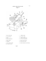
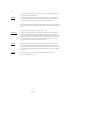
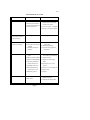
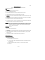
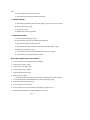
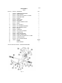
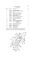
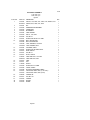
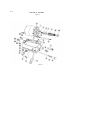
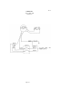
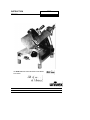
INSTRUCTION
MANUAL
8512
MAX SERIES Slicer
WE THANK YOU FOR YOUR PURCHASE OF OUR MODEL
8512 SLICER.
8512/498
EDS
8512
TABLE OF CONTENTS
DESCRIPTION
PAGE
Table of Contents
List of Illustrations
Introduction
Installation Instructions
Safety Warnings
Operating Instructions
Sharpening Instructions
Operator's Care of Slicer - Cleaning Instructions
Lubrication Instructions
Trouble Shooting Guide
Repair Instructions Including Disassembly, Replacement and Reassembly
Replacement Parts
Warranty Information
1
1
3
3
3
4
4-5
5-6
7
8
9-11
12-21
Back Cover
LIST OF ILLUSTRATIONS
ILLUSTRATIONS
PAGE
Figure 1
Figure 2
Figure 3
Figure 4
Figure 5
Figure 6
Figure 7
Figure 8
Figure 9
Figure 10
2
12- 13
14- 15
16
17
18
19
20-21
22
23
Overall View of Meat Slicer
Base Assembly
Casting and Blade Assembly
Arm Assembly
Slice Control Assembly
Carnage assembly
Sharpener Assembly
Electrical Assembly
Schematic 115V, 60HZ, 1PH, 100V, 50/60HZ, 1PH
Schematic 220V, 50hz, 1ph
Page 1
8512
OVERALL VIEW OF MEAT SLICER
MODEL 8512
Figure 1
1 INDICATOR LIGHT
9
2 ON-OFF SWITCH
10 ELECTRIC CORD
3 FENCE
11 CARRIAGE ARM KNOB
4 KNIFE SHARPENER
12 AUTO CLUTCH LEVER
5 KNIFE GUARD
13 PROTECTIVE GUARD
6 CARRIAGE
14 GRADUATED KNOB
7 ADJUSTMENT SPACER
15 SERIAL NAME PLATE (ON REAR)
8 LAST SLICE DEVICE
Page 2
CARRIAGE ARM
8512
INSTRUCTION MANUAL
INTRODUCTION
This manual contains instructions for the Installation, Operation, Care, Maintenance and Repair of the
Meat Slicing Machine. Disassembly, Repair, Replacement and Reassembly Instructions are included.
A trouble shooting guide is provided. A complete Replacement Parts List with identifying figures is
also included to facilitate identification and ordering of replacement parts.
INSTALLATION INSTRUCTIONS
INSPECTION
All Univex slicers are inspected and tested at the factory; however, they should be reinspected
carefully by the person making the installation for loose, damaged or broken parts. Detached parts and
fixtures should be checked against packing list to determine all are present. Any damages should be
reported to the carrier immediately, and any shortage of parts or fixtures reported to Univex
Corporation.
Warning: After slicer has been inspected, wash slicer completely with warm water and mild soap.
For SAFETY, follow the cleaning instructions on Page 6.
INSTALLATION
The most efficient installation of your Univex slicer will depend upon the layout of your kitchen.
Locate your slicer where it will save steps for the operator and be sure to provide sufficient clearance
around it for ease of maintenance and cleaning, as well as for efficient and safe use.
Slicer should be operated on a sturdy bench or table with the height determined to suit the operator. It
is most important that the forearm of the operator be at the proper level for ease and safety of
operat ion, as well as for maximum production. This height is considered optimum when the carriage
handle (Figure 1 [9]) of the slicer is at approximately the height of the operator's elbow when standing.
IMPORTANT
Warning/Caution: Electrical wiring instructions are found in the wiring diagram (Figures 9 & 10.)
Before making electrical connections, CHECK the specifications on the
nameplate to make sure that they agree with those on your electrical service. A
grounding type three-terminal plug is provided for safety. If you do not have a
mating receptacle, have a qualified electrician provide one with grounding
provisions in accordance with local safety codes.
IMPORTANT SAFETY WARNINGS
Warning: The slicer knife is extremely sharp! Never touch the knife, always keep hands and fingers
clear of the knife. Never run slicer without the guard or other parts in place and securely
fastened. Take extra care to avoid accidents by keeping the knife guard and sharpening
assembly cover ON at all times. When the machine is not in use, the slice adjustment
knob should be turned fully back to the closed position (beyond "0") so that the knife edge
is not exposed.
Observe the cleaning instruction on Page 7 for best results and for safety. Also remember
to always turn off the slicer and disconnect the electrical supply cord. When slicing,
always work the carriage using only the carriage arm handle (Figure 1 [9]). Do not hold or
push the carriage from any other place.
Page 3
8512
OPERATION INSTRUCTIONS
The Univex slicer is designed to meet the cook's demand for an efficient, sturdy slicer. The Univex slicer
will give unfailing performance over a period of years, when operated and maintained according to
instructions contained herein.
START/STOP SWITCH
The slicer is started by pulling the ON/OFF switch (Figure 1 [2]) out to the ON position. A pilot light
(Figure 1 [1]) is provided to indicate when the slicer is turned on.
SLICE ADJUSTMENT
Warning: Dial-type knob adjustment (Figure 1 [14]) allows for slice thicknesses ranging from paper thin
up to 5/8". Dial graduations allow you to precisely set up specific slice thicknesses for
various needs. When not in use, always return knob back to its fully closed position (beyond
"0") so that the knife edge is not exposed.
POSITIVE HOLD CARRIAGE
Caution: A last slice gravity feed grip (Figure 1 [8]) is provided which can be locked out of the way
when not required. Do not use this last slice device to work the carriage back and forth. Use
only the carriage arm handle (Figure 1 [9]).
Always make sure the carriage is positively secured to the slicer by checking to see that the
carriage arm knob (Figure 1 [11]) is fully tightened. Failure to do this could result in the
carriage striking and damaging the knife edge.
PROTECTIVE GUARD
WARNING:
The protective guard (Figure 1 [13]) covers the knife edge completely except under the
sharpener cover and the forward edge where slicing will be performed. This forward edge
is covered by the edge of the fence, but only when the slice adjustment is completely
closed.
The knife guard (Figure 1 [5]) can be removed for cleaning by unscrewing the knife guard
knob (Figure 3 [2]). For safety, keep the knife guard on at all times except when cleaning.
Never operate the slicer with the knife guard removed.
SHARPENING INSTRUCTIONS
This slicer is equipped with a knife having a concave or hollowed rear surface for superior slicing quality.
Of course, any knife, however superior, must be sharpened regularly and properly in order to produce
not only the highest quality slices, but also to allow it to maintain its productivity. The knife sharpener
(Figure 1 [4]) on this machine is a top mounted built-in design simplicity and ease of use. It even has an
automatic aligning feature.
Warning: The following sharpening procedure will provide high quality sharpening results and should
also be followed for safety considerations:
1. WARNING: Keep away from the knife edge.
2. Completely close the slice adjustment (beyond "0") so that the knife edge is not exposed.
Page 4
8512
3. The knife cutting area should be clean and free from food, especially grease. Grease
will ruin the ability of a grinding stone to sharpen an edge. The stone simply will not
cut. If cleaning is necessary, follow the procedure outlined on Page 6. Remember to
unplug the electrical supply cord.
4. Loosen sharpener lock pin (Figure 7 [30]) which bears against sharpener post, then lift
sharpener assembly (Figure 1 [4]) and rotate it 1/2 turn (180°). Then seat it down over
the knife.
5. Tighten sharpener lock pin (Figure 7 [30]). As the lock pin is tightened, it bears on the
sharpener post and automatically aligns the grinding and deburring stones to the
precise orientations which are preset at our factory.
6. Turn slicer ON. Depress the sharpener button on the back side of blade and hold in,
which will start the grinding wheel rotating. Run until the beveled cutting surface
cleans up. This can take from 30 seconds to several minutes depending on how dull the
blade was allowed to become. Release sharpener button.
7. Turn slicer OFF and check for the formation of a very slight burr on the side of knife
opposite the bevel which indicates complete grinding of the bevel. This slight burr can
be detected either visually or by picking with a small piece of stiff paper.
8. Turn slicer ON. Lightly press deburring (honing) button on the front side of blade and
hold for 1 to 2 seconds while you turn OFF the slicer. Blade should now be completely
sharpened and honed.
Caution: It is important for best slicing results not to deburr the knife too long or the keen
edge will be destroyed due to the formation of an undesirable second bevel on
the opposite side. This condition tends to be the primary cause of unsatisfactory
slicing results.
9.
Turn slicer OFF. Loosen lock pin, (Figure 7 [13]) then lift and return sharpener to its
storage position. Tighten lock pin.
10.
Clean slicer and knife according to the cleaning procedure on Page 7 in order to
thoroughly remove grinding debris.
OPERATORS CARE OF SLICER
CLEANING
Warning: 1.
Never touch the knife. Always keep your hands, fingers and arms clear of knife.
Warning: 2.
Turn off slicer and DISCONNECT ELECTRICAL CORD (Figure 1 [10]) before
cleaning. Leave protective guard in place.
3.
Turn slice adjustment knob (Figure 1 [14]) to the fully closed position (beyond
"0") so that the knife edge is not exposed.
Caution: 4.
Remove carriage assembly (Figure 1 [6]) which may be washed in a sink. Use
care in washing the sharply pointed prongs on the last slice feed grip, (Figure 1
[8]). Wash this area thoroughly. A small bristle br ush is recommended. Use only
warm water and mild soap. Rinse carriage assembly with warm water and dry
thoroughly using a clean soft cloth.
Page 5
8512
Never use detergents nor wash the slicer or any of its parts is a dishwashing machine or the
clear protective finish will be damaged.
Warning
5.
Wash body of slicer using warm water and mild soap using a clean soft cloth. Under no
circumstances should the slicer be hose rinsed. It is recommended that the cloth be folded
over a thin wooden stick when cleaning between the fence plate and the knife.
6.
Remove knife guard (Figure 1 [5]) by loosening knife guard knob (Figure 3 [35]) and pushing
the long stud upward to lift knife guard above surface of knife. Then carefully lift and remove
guard.
7.
Remove deflector (Fig. 3 [33]) by unscrewing knob (Fig. 3 [31 ]).
WARNING:
8.
CAREFULLY wash the front and rear of the knife with a cloth using warm water and mild
soap. It is recommended that the cloth be folded over a thin wooden stick as a further caution
to avoid accidental contact with the knife. CAREFULLY wash between the knife edge and
protective guard using a soft cloth inserted between knife edge and guard on both front and
rear of knife using extreme caution to never touch the knife edge. Rinse with warm water
applied with a cloth. Dry thoroughly with a clean soft cloth.
Caution:
9.
Following cleaning, a commercial non-toxic sanitizer may be wiped on the clean surfaces
with a soft clean cloth or sprayed as recommended on the container labeling. It is important
that the sanitizer be compatible with anodized aluminum or the clear protective finish on the
slicer will be damaged. Surface should be wetted completely, but not to the point of running
or puddling.
Warning:
10. Replace the knife guard. Never leave the slicer without its knife guard installed!
11. Replace Knife deflector (Fig. 3 [33]).
Page 6
8512
LUBRICATION INSTRUCTIONS
A = Clean and apply mineral
oil weekly.
C = 140 WT USDA oil.
Change when changing gears
B = Apply Petro-Gel (4400408) often as
required to maintain light film.
D = Lubricated for life.
Page7
8512
TROUBLESHOOTING GUIDE
TROUBLE
POSSIBLE CAUSE
1. Slicer will not operate.
1.1 Electrical service down.
2. Motor running, blade
not turning, (carriage)
still operating).
2.1 Broken gear
REMEDY
1.1 Check electrical service.
Replace fuse or reset circuit
1.2 Burned switch contacts.
breaker as necessary.
1.3 Motor capacitor defective.
1.2 Clean or replace. 1.3 Replace
1.4 Burned out motor.
1.4 Remove, test, repair or replace.
2.1 Replace gear
3. Carriage not operating 3.1 Loose or broken belt
3.1 Adjust belt tension or
(blade is operating).
replace belt.
3.2 Cone clutch assembly not
3.2 Adjust spring bushing.
engaging.
4. Excessive noise.
3.3 Connecting rod support
jammed.
3.3 Check for foreign objects in
mechanism.
4.1 Blade contacting knife
guard.
4.1 Check for loose knife guard
knob. Shim tapered bushing.
4.2 Deflector contacting blade. 4.2 Adjust deflector.
4.3 Sharpener contacting blade 4.3 Adjust cover from hitting
4.4 Connecting rod support
blade.
hitting bottom cover.
4.4 Pull bottom cover from
4.5 Fan hitting motor cover.
5. Not cutting properly.
support.
4.6 Damaged belt hitting
against motor cover.
4.5 Remove cover and adjust fan.
4.7 Reduction gearbox.
4.7 Replace.
5.1 Dull blade.
5.1 Sharpen blade following
outlined procedures.
5.2 Soft cheese.
4.6 Replace belt.
5.2 Chill for best slicing results.
Page 8
8512
REPAIR INSTRUCTIONS
(including disassembly, replacement and reassembly)
KNIFE (Removal) (Figure 3)
1. WARNING Disconnect electrical power cord.
2. Remove carriage assembly (Fig. 6).
3. Remove knife guard knob (Fig. 3 [35]) and carefully remove knife guard.
4. Loosen sharpener lock pin (Fig. 7 [13]), lift and relock in up position.
5. WARNING Using caution to avoid the sharp knife edge, remove the four screws (Fie. 3 [ 15]).
6. Carefully remove knife and set aside with its flat side down flush on a bench so the edge is
not exposed.
7. Reinstall new knife in the reverse procedures outlined above.
8. Even though a new knife is very sharp, the sharpening procedure specified on pages 6 and 7
should be performed to true the new knife's bevel to the slicer.
WARNING:
Worn knife should be disposed of in a safe responsible way, showing concern for
others who may handle it. It recommended that the edge of the knife be wrapped
several times with heavy tape and that a caution (CAUTION, SHARP EDGE) be
written on both sides of the knife.
KMFE SEAL (Figure 3)
1. Remove knife per above instructions.
2. Unscrew and remove tapered bushing (Fig. 3 [ 12]). Maintain shims that may have been used
in assembly.
3. Using a small screwdriver, carefully pry and remove the knife seal (Fig. 3 [13]) from knife
support (Fig.3 [8]).
4. Apply light film of mineral oil on outer diameter and lip of rubber seal.
KNIFE SUPPORT Figure 3
1. KNIFE SUPPORT ASSEMBLY
A. Remove knife per above instructions.
B. Loosen lama (Fig. 3 [36]) by holding tapered bushing (Fig. 3 [12]) while turning lama
with allen wrench.
C. Elevate left side or lama side of machine 3-1/2" to prevent oil from spilling.
D. Remove oil.
Page 9
8512
E. Remove lama by turning counter-clockwise.
F. Push knife support assembly from bottom and remove.
2. GEAR REPLACEMENT
A. With knife support assembly removed, check gear (Fig. 3 [7]) for wear. If worn, replace.
B. Remove snap ring (Fig. 3 [6]).
C. Pry gear off of shaft.
D. Replace gear in reverse procedures.
3. BEARING REPLACEMENT
A. Remove tapered bushing (Fig. 3 [12]).
B. Press shaft (Fig. 3 [5]) from top of blade support assembly.
C. Remove shim washers (7120040) if present.
D. Using a small screwdriver, carefully pry and remove the knife seal (Fig. 3 [13]).
E. Remove retaining ring (Fig. 3 [11)).
F. Invert assembly on bench and drive bearings and spacer from back side.
G. Put new bearing in by reversing above procedure.
MOTOR REPLACEMENT/OR BELT REPLACEMENT
1.
Follow procedure for removing blade support assembly.
2.
Remove acorn nuts (Fig. 2 [47]).
3.
Remove motor cover (Fig. 2 [45]).
4.
Loosen and pull fan (Fig. 2 [48]).
5.
Remove belt retainer (Fig. 2 [43]).
6.
Remove belt (Fig. 2 [50]).
a. If only replacing belt, put on new belt at this point and reassemble in reverse procedure.
7.
For motor replacement, continue disassembly by removing pulley (Fig. 2 [49]).
8.
Remove two remaining nuts (Fig. 8 [5]).
9.
Pull motor (Fig. 8 [1]) from housing.
10. Connect all wiring to new motor following wiring diagram on page 24 or 25.
11. Reverse above procedures to complete installation of new motor.
Page 10
8512
ELECTRICAL ASSEMBLY
1. WARNING DISCONNECT ELECTRICAL SUPPLY
2. Remove four rubber feet (Fig. 2 [24]) and 4 extension legs (Fig. 2 [52]).
3. Remove bottom cover (Fig. 2 [19]).
4. Remove casing cover (fig. 8 [22]).
5. Discharge capacitors by jumping across terminals with electrically protected screwdriver.
6. Remove reduction gear rod (Fig. 2 [34]) by removing two bolts (Fig. 2 [38]) and removing
set screw at reduction gear end.
7. Remove switch shaft (Fig. 8 [16]) by loosening nut (Fig. 8 [15]) near switch end.
8. Remove capacitor on left to access ground screw holding electrical equipment casing.
9. Remove electrical equipment casing by removing three screws (Fig. 8 [21 ]).
10. Replace capacitors (Fig. 8 [24]) if found to be defective.
11. Relay (Fig. 8 [7]) and switch (Fig. 8 [20]) can also be checked from this procedure.
12. Replace any defective electrical component and reverse procedures to reassemble.
Page 11
8512
BASE ASSEMBLY
Figure 2
ILLUS. NO.
PART NO.
1.
2.
3.
4.
5.
6.
7.
8.
9.
10.
11.
12.
13.
14.
15.
16.
17.
18.
19.
20.
21.
22.
23.
24.
25.
26.
27.
28.
29.
30.
31.
32.
33.
34.
35.
36.
37.
38.
8512300A
6509098
8512823
8512826
8512827
8512828
8512824
8512829
8512818
8512819
6509028
6509040
8512817
1012167
8512814
8512812
8512811
8512813
8512853
8512816
39.
40.
41.
42.
43.
44.
45.
46.
47.
48.
DESCRIPTION
SUPPORT, CARRIAGE, ALSO FIG. 4 [6]
SET SCREW, M6-1.0 X 8MM
BOLT, CONE CLUTCH
BUSHING, SPRING
SET SCREW, M5-0.8 X 5MM
SPRING
CAM
KNOB, CONE CLUTCH
BUSHING, AUTOMATIC
ROD, ROUND GUIDE
WASHER, M8
SCREW, SOC HD CAP M8-1.25 X 25MM
SCREW, CRANK ATTACHMENT
BALL BEARING
SCREW, CRANK ATTACHMENT
BALL BEARING
CRANK
SPACER
COVER, BOTTOM
SPACER
RESERVED
8512805 SUPPORT, CONNECTION ROD
8512808 KEY
8512855 FOOT
8512803A GEAR, REDUCTION
RESERVED
8512516 WASHER, M6
8512803 STUD
6509143 NUT M6-1.0
RESERVED
8512846 KEY
8512845 PULLEY, MOTOR
8512831 KEY, REDUCTION GEAR
8512830 ROD, REDUCTION GEAR
8512836 KEY
8512834 BALL BEARING
8512832 SUPPORT, ROD
8512833 SCREW, M6-1.0 X 20MM
ILLUS. NO 39 THRU 43 ARE AN ASSEMBLY
8512843
NUT
6509028
WASHER, M8
8512840
BEARING, BELT TENSION
8512841
SCREW, BEARING ATTACHMENT
8512838
SUPPORT, BELT TENSION
8512839
NUT
8512201
COVER, MOTOR
8512851
STUD
8512852
ACORN NUT, M6-1.0
8512848
FAN
Page 12
QTY.
1
4
1
1
2
1
1
1
1
1
2
2
1
1
1
1
1
1
1
1
1
1
4
1
4
4
4
4
1
1
1
1
1
1
2
1
1
1
1
1
2
1
2
2
1
8512
BASE ASSEMBLY
Figure 2 (CONT.)
ILLUS.NO.
49.
50.
51.
52
PART NO.
DESCRIPTION
QTY.
8512835
8512835A
8512837
8512837A
8512637
8512248
PULLEY (For 115V/100V)
PULLEY (For 220V)
V BELT (For 115V/100V)
V BELT (For 220V)
VENT, PLASTIC
LEG, EXTENSION
Page 13
1
1
1
1
1
4
8512
CASTING and BLADE ASSEMBLY
Figure 3
ILLUS. NO. PART NO. DESCRIPTION
1.
2.
3.
4.
5.
6.
7.
8.
9.
10.
11.
12.
13.
14.
15.
16.
17.
18.
19.
20.
21.
22.
23.
24.
25.
26.
27.
28.
29.
30.
31.
32.
33.
34.
35.
36.
37.
38
39
40
41
42
43
8512203
8512215
8512216
8512217N
8512218
8512220
8512222A
8512223
1030019
8512225
8512226
8512227
8612009
8512229
8512228
8512240
8512241
8512234
8512236
8512237
6509080
6509081
6509098
8512214
7510084
8512211
8512210
8512209
8512208
6509024
8512206
8512205
7510067
8512233
8512232
8512231
8512928
8512930
8512929
8612010
6509082
4400339
CASTING
PIN
SEAL
SEAL
ROD, CUTTER SUPPORT
RETAINING RING
GEAR
SUPPORT, BLADE, INCLUDES 4 THRU 13
SPACER, BEARING
BEARING
RETAINING RING
BUSHING, TAPERED
SEAL
GUARD, KNIFE
SCREW, FLAT HD M5-0.8 X 12MM
BLADE
BLADE SCRAPER
SCREW, BLADE SCRAPER
FENCE
SUPPORT, FENCE
SET SCREW
STUD, FENCE ADJUSTING
ACORN NUT, M8
SET SCREW, M6-1.0 X 10MM
SET SCREW, M6-1.0 X 16MMB
KNOB, GRADUATED
REAR WHEEL
FRONT WHEEL
RIVET
GRADUATED KNOB BUSH
KNOB, GUARD ATTACHMENT
DOWEL PIN
DEFLECTOR
SCREW, SOC HD CAP M6-1.0 X 20MM
KNOB, KNIFE GUARD
LAMA
ROD, KNIFE GUARD
RIGHT SUPPORT
SCREW M8-1.0 X 45MM
LEFT SUPPORT
PROTECTIVE GUARD
WASHER
LABEL, MAX ( NOT SHOWN)
Page 14
QTY
1
2
1
1
1
1
1
1
1
1
1
1
1
1
6
1
1
1
1
1
1
2
2
1
1
1
1
1
2
1
1
1
1
4
1
1
1
1
4
1
1
1
1
8512
CASTING and BLADE ASSEMBLY
Figure 3
Page 15
8512
ARM ASSEMBLY
Figure 4
ILLUS. NO. PART NO. DESCRIPTION
1.
2.
3.
4.
5.*
6.
7.
8.
9.
10.
11.
12.
13.
14.
15.
16.
17.
18.
19.
20.
21.
22.
23.
24.
7510038
8512314
8512313
8512312
8512301
8512300
8512316
8512318
8512317
6509033
6509032
8512308
6509031
6509028
6509042
8512319
6509044
6509045
6509046
8512325
8512326
1200377
RUBBER SHOCK ABSORBER
SPRING, DAMPER
SCREW, SOC HD CAP M8-1.25 X 30MM
ROD, ROUND GUIDE
BUSHING
ARM SUPPORT
BAR, FRAME
WASHER, EXTERNAL TOOTH
SCREW
NUT, JAM M10-1.5
STUD, BUSHING ADJUSTMENT
BOLT, BEARING LOCKING
BEARING
WASHER, M8
STUD, ARM ATTACHMENT
CARRIAGE ARM
KNOB, CARRIAGE ARM
HANDLE, CARRIAGE ARM
SCREW, HEX HD WASHER M6-1.0 X 15MM
CARRIAGE ANCHOR
STUD, CARRIAGE ANCHOR
OIL CUP
WASHER
SPRING, DAMPER
* 8512301 PART OF ILLUS NO. 6, CAN NOT BE PURCHASED
Page 16
QTY.
2
1
2
1
2
1
1
2
2
1
1
1
1
1
1
1
1
1
2
1
1
AS REQ
4
1
8512
ILLUS. NO.
PART NO.
SLICE CONTROL ASSEMBLY
Figure 5
DESCRIPTION
1.
2.
3.
4.
5.
6.
7.
8.
9.
10.
11.
12.
13.
14.
15.
16.
17.
18.
19.
20.
21.
22.
23.
24.
25.
26.
27.
28.
29.
30.
7510067
8512527
8512526
8512525
7510065
7512076
8512839
6509028
6509071
8512511
8512512
7510073
8512326
6509131
7510061
8512518
6509046
8512501
8512502
8512503
8512504
8512510
6509086
8512507
8512506
8512508
8512505
8512529
8512530
8512500
BOLT, SOC HD CAP M6-1.0 X 20MM
BOLT, HEX HD M8-1.25 X 30MM
JIB
WASHER, EXTERNAL TOOTH M6
SCREW, HEX HD M6-1.0 X 20MM
SUPPORT, TAPER
NUT, M8-1.25
WASHER, M8
STUD, CRANK
BLOCK, SLICE CONTROL MOVING
SHAFT, SLICE CONTROL
STUD, JIB ATTACHMENT
SET SCREW, M8-1.25 X 20MM
NUT, THIN M8-1.25
SPRING
SCREW, HEX HD M6-1.0 X 10MM
WASHER. M6
ECCENTRIC PIN
GEAR
WASHER. SPECIAL
BOLT, HEX HD M8-1.25 X 50MMT
SHAFT, GRADUATED KNOB
FLEXIBLE WASHER
WORM GEAR
BALL
ROLL PIN
BALL STUD
SCREW, PAN HD M5-0.8 X 25MM
NUT, M5-0.8
SLICE CONTROL GUIDE UNIT
Page 17
QTY.
2
1
1
2
2
1
1
2
1
1
1
1
1
2
1
1
1
1
1
1
1
1
1
1
1
1
1
1
1
1
8512
CARRIAGE ASSEMBLY
Figure 6
ILLUS NO.
PART NO.
DESCRIPTION
1
8512432
SPACER, ADJUSTMENT
2
8512437
STUD & KNOB, ADJUSTMENT SPACER
3
8512448
STUD
4*
8512433
BUSHING, ADJUSTMENT SPACER
5
8512925
SUPPORT, LAST SLICE DEVICE
6
8512924
HANDLE, LAST SLICE DEVICE
7
8512926
LAST SLICE DEVICE
8
6509153
KNOB, LAST SLICE DEVICE SHAFT
9
8512428
SHAFT, LAST SLICE DEVICE
10**
8512427
BUSHING, LAST SLICE DEVICE
11
8512425
CARRIAGE
12
8512438
NYLON PIP, ADJUSTMENT SPACER
13
8512434
SHAFT, ADJUSTMENT SPACER
RESERVED
14
15
8512431
NYLON PIP, LAST SLICE DEVICE
16
8512927
STUD, LAST SLICE DEVICE
17
6509038
SCREW, FLAT HEAD
18
6509058
BOX NUT, M10-1.5
19
6509059
WASHER, SPECIAL
20
8512439
STUD, CARRIAGE
* = PART OF ILLUS 1 (8512432), CANNOT BE PURCHASED SEPARATELY.
** = PART OF ILLUS 5 (8512925), CANNOT BE PURCHASED SEPARATELY.
Page 18
QTY.
1
1
1
1
1
1
1
3
1
1
1
1
1
8
1
1
1
1
1
8512
ILLUS NO.
PART NO.
SHARPENER ASSEMBLY
Figure 7
DESCRIPTION
1
2
3
4
5
6
7
8
9
10
11
12
13
14
15
16
17
18
19
20
21
22
23
24
25
26
27
28
29
30
7510151
6509153
6509151
6509150
6509149
6509125
6509137
6509138
7510120
8512728
6509147
6509127
6509128
6509129
6509130
6509131
6509134
6509133
6509135
6509136
6509132
6509143
6509144
6509142
6509141
6509128
6509126A
8512721
8512725
8512724
7510150
SHARPENER ASSEMBLY WITH COVER
KNOB, COVER
COVER, SHARPENER
NUT, COVER SPACER
SPACER. COVER
WASHER, SET PIN
SCREW
WASHER
SET PIN, SHARPENER
PIN, SHARPENER CASTING
BOLT, SHARPENER GUIDE
SPRING
BUSHING
STUD, HONING STONE
STONE, HONING
NUT
SPRING
BALL
BUTTON, DEPRESS
SET SCREW, DEPRESS BUTTON
WASHER, HORNING STONE
NUT, SHARPENING STONE
WASHER, SHARPENING STONE
STONE, SHARPENING
STUD, SHARPENING STONE
BUSHING
MOUNT, SHARPENER STONE
SUPPORT, SHARPENER
WASHER, M10
SCREW, HEX HD M10-1.5 X 25MM
LOCKING PIN, SHARPENER
Page 19
QTY.
1
1
1
1
1
1
1
1
2
2
2
1
1
1
1
2
2
2
2
1
1
1
1
1
1
1
1
1
1
1
8512
ILLUS. NO.
PART NO.
ELECTRICAL ASSEMBLY
115v, 60hz, 1ph
220v, 50hz, 1ph
Figure 8
DESCRIPTION
1.
8512844
8512844A
8512601
8512602
8512932
8512935
8512644
8512620
8512622
8512621
8512605
8512606
1814069
1814069A
8512624
8512627
8512615
8512614
8512613
4400053
4400053A
8512612
8512611
7120009
8512609
8512626
8512608
8512616
8512618
6509028
8512617
8512643
8512935
8512933
MOTOR, 115V, 60HZ, 1PH, 1/2HP, 100V, 50/60HZ, 1PH
MOTOR, 220V, 50HZ, 1PH, 1/2HP
KEY
RUBBER SHOCK ABSORBER
WORM GEAR
BUSHING/NUT
CORK WASHER
RELAY, 115V ONLY
NUT, M4-0.7
SCREW, PAN HD M4-0.7 X 10MM
BOLT, MOTOR LONG
BOLT, MOTOR SHORT
LAMP, WARNING, 115V/100V
LAMP, WARNING, 220V
FASTENER, CABLE
SCREW, PHIL HD SHEET METAL
KNOB, SWITCH
NUT, M6-10
SHAFT, SWITCH
CORD AND PLUG, 115V/100V
CORD AND PLUG, 220V
JOINT
NUT
SWITCH
SCREW, M5-0.8 X 12MM
COVER, CASING
ELECTRICAL EQUIPMENT CASING
CAPACITOR, 30MFD, 450V, (115V/100V)
CAPACITOR, 10MFD, 500V, (220V)
WASHER, M8
NUT, M8-1.25
WASHER
SPACER
SPRING
2.
3.
4.
5.
6.
7.
8.
9.
10.
11.
12.
13.
14.
15.
16.
17.
18.
19.
20.
21.
22.
23.
24.
25.
26.
27.
28
29
Page 20
QTY.
1
1
1
1
1
1
4
1
1
1
3
1
1
1
1
3
1
2
1
1
1
1
1
1
3
1
1
2
1
2
6
1
1
1
8512
ELECTRICAL ASSEMBLY
Figure 8
Page 21
8512
SCHEMATIC
115V, 60HZ, 1PH
100V. 50/60HZ, 1PH
Figure 9
Page 22
8512
SCHEMATIC
220V, 50HZ, 1PH
FIGURE 10
Page 23