1
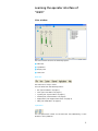
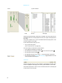
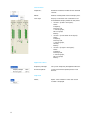
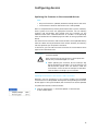
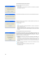
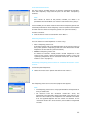
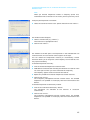
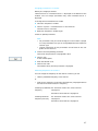
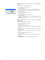
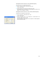
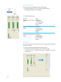
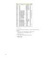
Wireless Systems Manager (WSM)
Instructions for use
NET 1
Contents
Important information regarding this manual .................................. 2
For your safety ......................................................................................... 2
Included with delivery ............................................................................. 2
Capabilities of the “WSM” ...................................................................... 3
System requirements .............................................................................. 3
Required hardware .............................................................................................. 3
Required operating system ............................................................................... 3
Putting the system into operation ....................................................... 4
Connecting the NET 1 to a PC ............................................................................ 4
Installing the “WSM” software ......................................................................... 4
Launching the “WSM” PC software .................................................................. 4
Learning the operator interface of “WSM” ......................................... 5
Main window ........................................................................................................ 5
Overview of menus .............................................................................................. 7
Configuring devices ................................................................................. 9
Updating the firmware in the connected devices ......................................... 9
“Easy Setup” frequency management .......................................................... 12
Configuring individual receivers ..................................................................... 16
Working with panels ............................................................................ 20
The panel view .................................................................................................... 20
Monitoring devices ............................................................................... 23
Observing and evaluating the field strength display ................................. 23
Retrieving messages from the receivers ....................................................... 23
If problems occur ................................................................................... 25
Hardware ............................................................................................................. 25
Software .............................................................................................................. 25
Glossary ................................................................................................... 26
You have made the correct selection!
These Sennheiser products will satisfy for years on the basis of their
reliability, economy and simple operation. Your guarantee is the good
name of Sennheiser and the competence it has gained in over 60 years of
manufacturing high-quality electroacoustic products.
Please take a few minutes to read this manual. We wish to help you enjoy
this technology quickly and easily.
1
Important information regarding this
manual
This manual describes the “Wireless Systems Manager” (WSM) PC
software for the NET 1 system.
Information on the NET 1 system as well as the transmitters and receivers
can be found in the individual user guides.
Note:
The operator interface for the “WSM” PC software is only available in
English.
For your safety
Caution!
Warning regarding data loss!
Individuals who are not trained in the operation of
computers can unintentionally alter computer files,
corrupt or erase them!
왘 Ensure that only competent individuals operate the
computer on which the “WSM” software is installed.
Note:
y Save all files of your “WSM” on removable media (e. g. CD-ROM) as
soon as you have created or changed a configuration! Store the
removable medium securely in a safe location!
y If you use a firewall, ensure that the “WSM” is not blocked by its
settings.
Included with delivery
The following items are included:
y 1 “Wireless Systems Manager” (WSM) PC software on the CD
y 1 Installation instructions in the booklet accompanying the CD
y 1 Instructions as a PDF file on the CD
y 1 Online help on the-CD
2
Capabilities of the “WSM”
The “Wireless Systems Manager” (WSM) permits real-time monitoring as
well as remote control of all relevant receiver parameters in the live mode.
Using the “WSM” PC software, you can:
y Display and monitor the receivers connected to the NET 1 system,
y Configure the receivers,
y Perform a frequency preset scan,
y Control 3000/5000 systems, combined systems and multichanel
systems with more than 20 channels,
y Update the firmware of the NET 1,
y Update the firmware of the receivers and transmitters via the NET 1.
System requirements
Required hardware
Processor:
Intel Pentium 4 or AMD Athlon XP, 2 GHz or higher
RAM:
at least 512 MB (1 GB recommended)
Hard drive:
min. 30 MB available
Drives:
• CD-ROM or DVD-ROM
• drive for data backup
Ports:
LAN 1 Ethernet port (100 Mbit)
Screen resolution:
1280 x 1024 pixels
Required operating system
The “WSM” PC software supports the following operating systems:
y Windows 2000 with SP4 or higher
y Windows XP Professional with SP2 or higher
y Windows XP Home Edition with SP2 or higher
3
Putting the system into operation
Connecting the NET 1 to a PC
How to connect the NET 1 to a PC is shown in the user guide for the NET 1.
Installing the “WSM” software
Install the “WSM” PC software by following procedure below:
왘 Close all currently running programs, including those running in the
background (e. g. anti-virus programs).
왘 Place the WSM CD in the CD-ROM drive of your computer.
The installation wizard starts automatically and guide you through the
installation.
Note:
If the wizard does not start automatically, use Explorer to change to the
CD drive containing the WSM CD and double-click on the “setup.exe”
file
왘 Follow the wizard's instructions.
The installation wizard suggests installation on the program folder on
the “C:\” drive as the subfolder “…\Sennheiser\WSM”. You can
change the install path by clicking on “Change directory”.
Launching the “WSM” PC software
Note:
Before you launch the “WSM” software, you must switch on all
receivers and the NET 1.
To launch the “WSM” PC software:
왘 Double-click on the program icon on the desktop or click on “Start” >
“Programs” > “Wireless Systems Manager”.
This launches the “WSM” software.
4
Learning the operator interface of
“WSM”
Main window
The main window contains the following regions:
쐃 Menu bar
쐇 Symbol bar
쐋 Display area
쐏 Status bar
Menu bar
The menu bar is always visible.
You can select from the following menus:
y File (see “File Menu” on page 7)
y View (see “View Menu” on page 7)
y System (see “System Menu” on page 7)
y Channel (see “Channel Menu” on page 8)
y Applications (see “Applications Menu” on page 8)
y Help (see “Help Menu” on page 8)
Symbol bar
You can operate the “WSM” via the menu bar and, additionally, via the
buttons in the symbol bar.
5
Display area
Scene
System window
Panel
Devices
Messages
With the standard settings, the display is divided in two. The panels for the
connected receivers are displayed on the left; this region is designated as
the scene.
The system window with a list of connected receivers displayed in a tree
structure appears at the right.
In the scene (Master Scene) you can:
y Set up and move panels
(see “The panel view” on page 20.),
You can enlarge or reduce the system window :
y by dragging the border on the left side,
y by clicking on the maximize symbol
y by clicking the close symbol
or the minimize symbol
,
,
y by selecting the menu item “View” > “System Window” hide/show,
y by clicking the register Devices or Messages, toggle between the tree
structure and the message list.
Status bar
The last message from the system window is displayed on the left in the
status bar (Register: Message), even if the system window is not visible.
The mode of operation as well as the current date and time are displayed
in the status bar on the right.
6
Overview of menus
File Menu
Open Configuration...
Opens a saved configuration.
Save Configuration
Saves the current configuration under the
same name as a “*.xml” file.
Save Configuration As...
Saves the current configuration under a new
name.
Save Message Log...
Saves issued messages as a “*.log” file.
Exit
Terminates the “WSM”.
View Menu
System Window
Shows or hides the system window in the
display region on the right-hand side.
Show Grid
Shows or hides the grid for aligning the
panels.
Snap to grid
Aligns the panels to the grid in the
background if you move the panels.
Auto Arrange
Automatically arranges the panels side-byside on the operator interface.
System Menu
Remote Access
Activates/deactivates access to parameter
changes in the receivers in the device
window.
Refresh Device List
Updates (refreshes) the device list. New
devices are displayed, previously deleted
panels reappear in the display area.
7
Channel Menu
Properties...
Retrieves the device window for the selected
receiver.
Delete
Deletes marked panels from the display area.
View Style
Displays a submenu with a selection list of
three different display modes for the panels:
y Variant 1 (at left in the figure):
Name
Frequency,
Diversity A/B,
2 x HF bar graph,
Dev. bar graph,
Battery
y Variant 2 (in the center of the figure):
Name
Frequency,
Diversity A/B,
2 x HF bar graph,
AF Peak,
Battery
y Variant 3 (at right in the figure):
Name
Frequency,
Diversity A/B,
1 x HF bar graph,
Dev. bar graph,
Battery
Applications Menu
Frequency Manager
Call up the “Frequency Management Wizard”.
Firmware Update
Starts the firmware update process in the
devices.
Help Menu
About...
8
Opens a new window in which the version
number is displayed.
Configuring devices
Updating the firmware in the connected devices
Note:
y Only the firmware is updated; the device settings remain the same.
y The firmware in the dual receiver EM 3532 is not updated.
NET 1 is compatible with previously delivered wireless systems. However,
these systems must have the appropriate firmware. You can identify
receivers and transmitters that already have this firmware via the
additional menu item “Software Revision” or “SW REV” in the operating
menu of the device or the identifying mark “NET” on the type plate of the
device.
The firmware in the receivers and the transmitters can be updated directly
from the “WSM”. During installation of the “WSM” software, all necessary
files are copied to your computer's hard drive.
In the future, you can find the current firmware on the Sennheiser home
page at www.sennheiser.com.
Caution!
Risk of data loss if transmission is interrupted during
firmware update!
Data may be lost if the transmission is interrupted. The
devices may also be damaged as a result.
왘 When updating the firmware, do not interrupt any
device connection to the NET 1 or to the receivers. Do
not disconnect power from the devices! Hold the
transmitters in front of the infrared port of the NET 1
until the LEDs 1 to 10 light up in succession.
Updating the firmware in the receivers and transmitters
Receivers that are grayed out in the system window have outdated
firmware that must be updated. Although the corresponding transmitters
do not appear in the system window, their firmware must also be updated.
To update the receivers and transmitters:
왘 Click on “Applications” > “Firmware Update” in the menu bar.
A new window opens.
9
Transmitting the firmware to the receivers
To transmit the firmware to the receivers:
왘 Click on “OK”.
The firmware is transmitted to the receivers. On the NET 1, the yellow
LED “REMOTE” lights up.
The window to the left opens. The firmware is transmitted to the receivers.
After the firmware in the receivers has been updated successfully, the
window to the left appears
왘 Click on “OK”.
Note:
While the firmware is being transmitted to a receiver, the receiver's
display switches shut off.
Once the firmware has been transmitted successfully, the receiver's
display switches on again. The receiver appears as active in the system
window.
Transmitting the firmware to the transmitters
The window to the left opens. You can now update the firmware in the
transmitter. On the NET 1, the yellow LED “DATA LINK” flashes. LEDs 1 to
10 light up briefly in succession, indicating that the NET 1 is ready to
update the firmware in the transmitters.
왘 Hold the first transmitter in front of the infrared port (“DATA LINK”) on
the NET 1.
The firmware is transmitted. During this operation, LEDs 1 to 10 flash
simultaneously. Once the transmission has been completed, LEDs 1 to
10 light up briefly in succession. You can now place the transmitter to
the side.
왘 Hold all remaining transmitters in front of the infrared port on the
NET 1 in succession.
왘 Once you have updated all transmitters, click on “Close”.
The window closes.
10
Updating the firmware in the NET 1
The NET 1 is delivered with the most current firmware. You can transmit
future firmware to the NET 1 by following the procedure below.
To update the NET 1:
왘 Click on “Applications” > “Firmware Update” in the menu bar. A new
window opens.
왘 Click on “OK”.
The firmware in the NET 1 is updated.
On the NET 1, the yellow LED “REMOTE” lights up.
The window to the left opens.
The firmware is transmitted to the NET 1.
After the NET 1 has been updated successfully, the window to the left
appears.
왘 Click on “OK”.
The window to the left opens. This window requests, once again, that you
hold the transmitters in front of the infrared port. However, since you have
already updated the transmitters, ignore this request.
왘 Click on “Close”.
11
“Easy Setup” frequency management
Using the “Easy Setup” frequency management capability, you can:
y Distribute frequencies in the channel bank to devices from the
“evolution wireless G2” series that are connect to the NET 1,
y Detect occupied frequencies,
y Allocate unused frequencies to the receivers.
You can also configure individual receivers using “Easy Setup” (see
“Configuring individual receivers” on page 16).
To launch “Easy Setup” frequency management:
왘 Click on “Applications” > “Frequency Manager” in the menu bar.
The “Frequency Management Wizard” window opens.
왘 Select the “Easy Setup” option and click on “Next >”.
Overview of “Easy-Setup”
Launch Easy Setup
Show connected receivers
Perform a frequency preset scan?
YES
NO
Perform a frequency preset scan
“evolution wireless G2” series
see page 13
Allocate frequencies without a scan
“evolution wireless G2” series
see page 15
Display of unused/occupied frequencies
Select frequency bank
Allocating frequencies manually or automatically
12
Show connected receivers
The “Easy Setup” window displays all receivers connected to the NET 1
with their frequency range and the ports on the NET 1 occupied by
receivers.
Note:
Use “< Back” to return to the previous window; use “Next >” to
proceed to the next window. Use “Cancel” to terminate “Easy Setup”.
In this window you can select a receiver with which a frequency preset scan
should be performed or whose frequency values should be transmitted to
all other receivers without a frequency preset scan (see next section).
To select a receiver:
왘 Click on the line in the list and confirm with “Next >”.
Allocating frequencies to receivers
You can allocate unused frequencies in various ways:
y After a frequency preset scan:
To find occupied as well as unused frequencies in the current vicinity of
the system, perform a frequency preset scan. Then allocate the unused
frequencies to the receivers (see next section).
y Without a frequency preset scan:
To allocate to receivers already known unused frequencies in the
vicinity of the system, specify these frequencies without a scan (see
“Specifying frequencies for an “evolution wireless G2” series receiver
without a scan” on page 15).
Performing a frequency preset scan for an “evolution wireless G2” series
receiver
To find occupied frequencies:
왘 Select the “Preset Scan” option and confirm with “Next >”.
The frequency preset scan starts and a progress bar appears.
Note:
y The frequency preset scan is always performed for all frequencies in
every channel bank.
y For receivers from the “evolution wireless G2” series, the
frequencies are organized in banks and stored in the receivers. For
EM 3532 dual receivers, the frequencies are selected from tables
that are supplied together with the “WSM” PC software. As for
“evolution wireless G2” series receivers, these tables are organized
in banks.
13
Allocating the identified frequencies to the receivers
After the frequency preset scan has been performed, the number of
unused frequencies identified in each bank is displayed.
To allocate frequencies to receivers:
왘 Click on a bank whose frequencies you want to allocate to the receivers
and confirm with “Next >”.
The window to the left opens. The frequencies in the selected bank are
listed at the left. A list of receiver names appears at the right.
You can allocate the frequencies manually or automatically. Manual
allocation allows you to assign the same frequency to two receivers. This
may improve reliability.
To allocate frequencies manually:
왘 Click on the desired frequencies listed at the left.
왘 Hold down the mouse button and drag the selection to a receiver in the
list at the right to which you want to allocate this frequency.
The frequency appears after the name of the receiver.
왘 Repeat this procedure to allocate frequencies to other receivers.
왘 Confirm with “Finish”.
The “Frequency Management Wizard” window closes. The selected
frequencies are updated in the display field and transmitted to the
devices.
To allocate frequencies automatically instead:
왘 Click on the “Allocate automatically” button.
The frequencies are allocated to the receivers in succession
automatically.
왘 Confirm with “Finish”.
The “Frequency Management Wizard” window closes. The selected
frequencies are updated in the display field and transmitted to the
devices.
14
Specifying frequencies for an “evolution wireless G2” series receiver
without a scan
Note:
When you allocate frequencies without a frequency preset scan,
interference with transmitters in the vicinity of the system may result.
To display the frequencies in the bank:
왘 Select the “Continue without scan” option and confirm with “Next >”.
The window to the left opens.
왘 Select a channel bank (e. g. “Bank 1”).
The listed item is highlighted in blue.
왘 Confirm with “Next >”.
The window to the left opens. The frequencies in the selected bank are
listed at the left. A list of receiver names appears at the right.
You can allocate the frequencies manually or automatically. Manual
allocation allows you to assign the same frequency to two receivers. This
may improve reliability.
To allocate frequencies manually:
왘 Click on the desired frequencies listed at the left.
왘 Hold down the mouse button and drag the selection to a receiver in the
list at the right to which you want to allocate this frequency.
The frequency appears after the name of the receiver.
왘 Repeat this procedure to allocate frequencies to other receivers.
왘 Confirm with “Finish”.
The “Frequency Management Wizard” window closes. The selected
frequencies are updated in the display field and transmitted to the
devices.
To allocate frequencies automatically instead:
왘 Click on the “Allocate automatically” button.
The frequencies are allocated to the receivers in succession
automatically.
왘 Confirm with “Finish”.
The “Frequency Management Wizard” window closes. The selected
frequencies are updated in the display field and transmitted to the
devices.
15
Configuring individual receivers
You can also configure individual receivers.
Note:
To change the parameters in a receiver, “Remote Access” must be
active (see “Changing parameters in a receiver” on page 17.).
Retrieving an overview of parameters
To retrieve the parameters from a receiver:
왘 Click on a receiver in the system window or on the corresponding panel.
왘 Click on the desired receiver with the right mouse button and select
“Properties” in the contextual menu.
The window to the left opens.
The parameters for the device appear In the left column (Name). To the
right, the associated values (Value) and units (Units).
16
Changing parameters in a receiver
Before you change parameters:
“Remote Active” or “Remote Inactive” is displayed at the bottom of the
window. You can change parameters only when “Remote Active” is
displayed.
To change to the “Remote Active” mode:
왘 Close the “Properties” window.
왘 Click on “System” > “Remote Access”.in the menu bar.
The menu item is activated.
왘 Open the “Properties” window again.
To edit or update parameters:
Note:
y For parameters that you cannot change, the “Set” button is grayed
out. The parameters that you can change depend on the respective
receiver type.
y Specific information on the parameters can be found in the user
guides for the receivers.
왘 Click on the corresponding parameter.
The line for the parameter is highlighted in blue.
왘 Click on “Set”.
A new window opens.
왘 Enter the desired value.
왘 Confirm with “OK”.
The window closes; the new parameter is displayed.
Allocating frequencies to receivers
You can change the frequency for the receiver. To do so, you can:
y Select a predefined frequency in the receiver
or
y Program any frequency value within the frequency range applicable to
the receiver and then select this frequency.
Selecting a predefined For “evolution wireless G2” series receivers
frequency
see page 18
For EM3532 dual receivers see page 19
Selecting a defined
frequency manually
For “evolution wireless G2” series receivers
see page 18
For EM3532 dual receivers see page 19
17
Setting “evolution wireless G2” series receivers to a new, predefined
frequency
To set the receiver to a predefined frequency:
왘 Click on “Bank” and confirm with “Set”.
A new window opens.
왘 Select a predefined channel bank from the list field and click on “OK”.
The window closes. The selected frequency bank appears in the
“Properties” window.
왘 Click on “Channel” and confirm with “Set”.
A new window opens.
왘 Select a predefined channel and click on “OK”.
The window closes.
The selected channel appears in the “Properties” window. The
frequency is transmitted to the receiver and appears in the
“Properties” window.
Setting “evolution wireless G2” series receivers to a new, manually
defined frequency
To allocate a new frequency to the receiver:
왘 Click on “Bank” and confirm with “Set”.
A new window opens.
왘 Select bank “U” and click on “OK”.
The window closes. The channel bank “U” appears in the “Properties”
window.
왘 Select the channel in which the new frequency value should be saved
and click on “OK”.
The window closes. The selected channel appears in the “Properties”
window.
왘 Click on “Frequency” and confirm with “Set”.
A new window opens.
왘 Using the arrow buttons, select the desired frequency value and click
on “OK”.
The window closes.
The frequency value is saved and transmitted to the receiver.
18
Setting EM 3532 dual receivers to a new, predefined frequency
To set the receiver to a predefined frequency:
왘 Click on “Frequency Table” and confirm with “Set”.
A new window opens.
왘 Select a frequency from the list field and click on “OK”.
The window closes. The frequency is transmitted to the receiver and
appears in the “Properties” window.
Setting EM 3532 dual receivers to a new, manually defined frequency
To allocate a new frequency to the receiver:
왘 Click on “Frequency” and confirm with “Set”.
A new window opens.
왘 Select the desired values in the “Frequency”, “Channel Index” and
“Channel” fields and click on “OK”.
The new frequency value appears in the “Properties” window together
with the channel number.
19
Working with panels
The panel view
Every panel displays a receiver that is connected to the NET 1.
Layout of the panel
Name of the device
The name of the device is read from the device and displayed, or, if the
device has no name, “DEVICE” is displayed together with a sequentially
assigned number. You can change the name of the devices. The name is
restricted to 10 characters.
Frequency display
The frequency of the receiver appears below its name.
Diversity channels
The currently active channel “A” or “B” is displayed in green
.
Field strength display
The bar height indicates the current field strength. The horizontal yellow
line indicates the limit set for the squelch level. If the field strength is
below the limit for the squelch level, the bar appears in red and sound is
suppressed.
Modulation (Deviation)
Level indicator for the audio level at the transmitter.
Variants 1 and 3:
The modulation is shown as a bar graph.
Variant 2:
The modulation is displayed in three steps, each
with a different color that corresponds to the
colors of the bar graph display.
Battery status
The battery symbol indicates the charge level battery/batteries. The
segments remain green until the battery is almost fully discharged. If a
critical charge level is reached, all segments start to flash in red. In addition
a message appears in the “Messages” window.
20
Working with panels
To work with the panels:
왘 Select the panel you wish to work with.
왘 Click on the panel using the right mouse button.
A contextual menu appears.
Properties...
Opens the device window in which you can set various parameters in the
selected receiver.
Delete
Removes the selected panel from the display field. The receiver continues
to appear in the system window and can be pulled into the display field.
View Style
Displays a submenu with a selection list of three different display modes
for the panels:
Show/hide panel
To provide a better overview, you can remove from the display field panels
that you do not want to monitor or configure.
왘 Select “Delete” in the contextual menu.
The panel no longer appears in the display field.
To restore deleted panels:
왘 Click on the receiver in the system window and hold down the mouse
button.
왘 Now drag the receiver into the display field.
A new panel appears.
To show all receivers in the display field as panels:
왘 Click on “System” > “Refresh Device List” in the menu bar.
Note:
The display field can hold a maximum of 30 panels. If more than 30
receivers are connected, you can use the scroll bar to bring the
remaining panels into view.
21
Change the panel view
The “WSM” offers three different styles for the panels.
왘 Make your selection in the “View Style” contextual menu.
An additional contextual menu appears.
왘 Select the desired style:
Variant 1:
(shown at the left in the
figure)
Name
Frequency
Diversity A/B,
2 x HF bar graph,
Dev. bar graph,
Battery
Variant 2:
Name
(shown at the center in the Frequency
figure)
Diversity A/B
2 x HF bar graph
AF Peak
Battery
Variant 3:
(shown at the right in the
figure)
Name
Frequency
Diversity A/B
1 x HF bar graph
Dev. bar graph
Battery
Moving panels
If you want to observe a specific panel, you can move the corresponding
panel on the screen.
왘 Click on the panel and hold down the mouse button.
왘 Drag the panel to the desired position in the display field.
If “Snap to Grid” is activated, the panel is aligned to the grid
automatically.
22
Monitoring devices
Observing and evaluating the field strength display
Observing the field strength and recognizing deviations
The current values of the field strength are displayed as bars in the panels.
The horizontal yellow line indicates the squelch level.
If the field strength drops below the squelch level, the bar displayed
appears in red and the corresponding receiver is silenced.
If the field strength is above the squelch level, the bar displayed appears
in green.
To change the value of the squelch level:
왘 Click on the panel using the right mouse button.
A contextual menu appears.
왘 Click on “Properties...”.
The “Properties” window opens.
왘 Select the “Squelch” line and confirm with “Set”.
A new window opens.
왘 Click on the arrow next to the list field and select a threshold for the
squelch level.
Low:
Low threshold value
Mid:
Moderate threshold value
High:
High threshold value
왘 Confirm with “OK”.
The window closes and the set threshold value appears in the
“Properties” window.
왘 Close the “Properties” window.
The yellow line for the squelch level in the panel readjusts accordingly.
Retrieving messages from the receivers
The “WSM” allows all connected receivers to be monitored during
operation. Notifications and messages about problems appear in the
display field of the “Messages” system window. In addition, the “WSM”
identifies priorities regarding the messages.
The retrieve the messages:
왘 Click on the “Messages” register in the system window.
If the system window is not visible:
왘 Click on “View” > “System Window” in the menu bar.
The system window opens.
왘 Click on the symbol
to maximize the window.
23
Saving messages
You can save the retrieved messages as a “*.log” file using the following
procedure:
왘 Click on “File” > “Save Message Log...” in the menu bar.
The dialog window “Save the logfile as” opens.
왘 Give the file a name.
왘 Select a folder where you want to save the file.
왘 Click on “Save”.
The file is saved.
24
If problems occur
Hardware
First check the connections and the cables for the devices (see NET 1 user
guide).
Software
In the future, the Sennheiser home page will have an FAQ (Frequently
Asked Questions) area. Recurring problems and possible solutions will be
listed there.
The program does not launch
왘 Check that your PC satisfies the system requirements (see “System
requirements” on page 3.).
왘 Check the settings of your firewall; the “WSM” may be blocked by a
setting.
Receiver panel is grayed out
The firmware in the receiver has not yet been updated.
왘 Update the firmware in the receiver (see “Updating the firmware in the
connected devices” on page 9.).
Contact your Sennheiser representative if problems with your system arise
that you cannot resolve with the suggestions given.
25
Glossary
Deviation
Modulation associated with the receiver;
Represented as a bar diagram (Dev)
Easy Setup
Function for allocating frequencies
Firmware
Software that resides on a chip in the device.
It can and, sometimes, must be updated.
The current firmware is supplied on the CD.
In the future, new versions will be available from the Sennheiser home
page.
Frequency preset scan
Function for detecting (identifying) unused and occupied frequencies in
the immediate vicinity; the identified frequencies can be allocated to the
receivers manually or automatically.
Panel
Window in the display field; the panels contain, among other
information, the name of the device, the current frequency and the field
strength display.
Squelch
Squelch is the term used to describe the suppression of interfering noises
during transmission.
Scene
Left portion of the display field containing the panels for the devices.
26
Sennheiser electronic GmbH & Co. KG
30900 Wedemark, Germany
Phone +49 (5130) 600 0
Fax +49 (5130) 600 300
www.sennheiser.com
Printed in Germany
Publ. 08/06
516555/A1