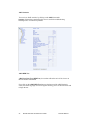
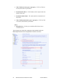
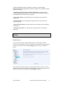
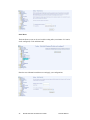
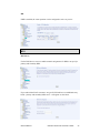
1
6238-I2 Wi-Fi Router with VoIP User’s Guide February 2007 Document Part Number: 6238-A2-ZB20-20 Zhone Technologies @Zhone Way 7001 Oakport Street Oakland, CA 94621 USA 510.777.7000 www.zhone.com [email protected] COPYRIGHT 2007 Zhone Technologies, Inc. All rights reserved. This publication is protected by copyright law. No part of this publication may be copied, distributed, displayed, modified, transmitted, stored in a retrieval system, or translated without express written permission from Zhone Technologies, Inc. Acculink, ADSL/R, Bitstorm, Comsphere, DSL the Easy Way, ETC, Etherloop, FrameSaver, GranDSLAM, GrandVIEW, Hotwire, the Hotwire logo, iMarc, Jetstream, MVL, NextEDGE, Net to Net Technologies, OpenLane, Paradyne, the Paradyne logo, Performance Wizard, ReachDSL, StormPort, TruePut are registered trademarks of Zhone Technologies, Inc. BAN, Connect to Success, GigMux, Hotwire Connected, JetFusion, JetVision, MALC, MicroBurst, PacketSurfer, Quick Channel, Raptor, Reverse Gateway, SLMS, Spectrum Manager, StormTracker, ZEdge, Zhone, ZMS, and the Zhone logo are trademarks of Zhone Technologies, Inc. All other products names or service marks mentioned herein are the trademarks, trade names and service names of their respective owners. Zhone Technologies makes no representation or warranties with respect to the contents hereof and specifically disclaims any implied warranties of merchantability, noninfringement, or fitness for a particular purpose. Further, Zhone Technologies reserves the right to revise this publication and to make changes from time to time in the contents hereof without obligation of Zhone Technologies to notify any person of such revision or changes. 2 6238 Wi-Fi Router with VOIP User’s Guide 6238-A2-ZB20-10 Table of Contents General Information ............................................................................................... 5 Package Contents .................................................................................................. 5 Safety Instructions—Please Read ......................................................................... 5 Front Panel View .................................................................................................. 6 Indication .............................................................................................................. 6 Back Panel View................................................................................................... 8 Installing the Router ............................................................................................... 9 Connect the ADSL Line to a POTS Splitter (Optional)........................................ 9 Connect the ADSL Line to the Router.................................................................. 9 Connect the PC to the Router................................................................................ 9 Connect a Printer or Server to the Router ........................................................... 10 Connect the Telephone to the Router.................................................................. 10 Connect the Router to a Phone Jack.................................................................... 10 Connect the Power Adapter ................................................................................ 10 Installation Diagram............................................................................................. 11 Mounting the Router ........................................................................................... 12 USB Driver Installation ........................................................................................ 13 Configuring Your Computer ............................................................................... 16 Windows 2000 .................................................................................................... 16 Windows XP ....................................................................................................... 17 Log in to the Router.............................................................................................. 18 Device Info ............................................................................................................. 19 Summary ............................................................................................................. 19 WAN................................................................................................................... 20 Statistics .............................................................................................................. 20 Route................................................................................................................... 23 ARP..................................................................................................................... 23 DHCP.................................................................................................................. 25 Quick Setup ........................................................................................................... 25 Advanced Setup..................................................................................................... 30 WAN................................................................................................................... 30 Local Area Network (LAN) Setup...................................................................... 34 Ethernet Mode..................................................................................................... 35 NAT .................................................................................................................... 35 Firewall ............................................................................................................... 38 Quality of Service ............................................................................................... 43 Routing................................................................................................................ 47 DNS .................................................................................................................... 49 ADSL .................................................................................................................. 50 Port Mapping ...................................................................................................... 52 Wireless.................................................................................................................. 53 Basic.................................................................................................................... 53 Security ............................................................................................................... 54 MAC Filter.......................................................................................................... 55 Wireless Bridge................................................................................................... 56 6238-A2-ZB20-10 6238 Wi-Fi Router with VOIP User’s Guide 3 Advanced ............................................................................................................ 56 Quality of Service ............................................................................................... 58 Station Info ......................................................................................................... 60 Voice....................................................................................................................... 61 SIP Basic............................................................................................................. 61 SIP Advanced ..................................................................................................... 62 Dial Plan ............................................................................................................. 65 Phonebook .......................................................................................................... 66 SIP Provision ...................................................................................................... 67 Call Features ....................................................................................................... 68 Diagnostics ............................................................................................................. 69 Management .......................................................................................................... 70 Settings................................................................................................................ 70 System Log ......................................................................................................... 72 SNMP.................................................................................................................. 73 TR-069 Client ..................................................................................................... 74 Internet Time....................................................................................................... 74 Access Control .................................................................................................... 75 Update Software.................................................................................................. 78 Reboot Router ..................................................................................................... 79 4 6238 Wi-Fi Router with VOIP User’s Guide 6238-A2-ZB20-10 General Information The 6238 Wi-Fi Router with VOIP is a 3-in-1 router having the functions of a standard ADSL router, plus voice capabilities and wireless accessibility, all in one box. These three features add convenience and provide increased functions to one router. Package Contents Included in the package is one of each of the following: • • • • • • • Wi-Fi Router AC power adapter USB cable RJ11 telephone cable RJ45 Ethernet cable Quick Installation Instructions CD containing USB drivers and user’s guide Safety Instructions—Please Read • • • • • • Place your router on a flat surface close to the cables in a location with sufficient ventilation. To prevent overheating, do not obstruct the ventilation openings of this equipment. Plug this equipment into a surge protector to reduce the risk of damage from power surges and lightning strikes. Operate this equipment only from an electrical outlet with the correct power source as indicated on the adapter. Unplug equipment first before cleaning. A damp cloth can be used to clean the equipment. Do not use liquid / aerosol cleaners or magnetic / static cleaning devices. Do not open the cover of this equipment. Opening the cover will void any warranties on the equipment. 6238-A2-ZB20-10 6238 Wi-Fi Router with VOIP User’s Guide 5 Front Panel View LED Power ADSL / LINK ADSL / ACT LAN 1-4 USB Device Mode Indication Solid The router is on. No light The router is not on. Check if the AC power adapter is connected to the router and plugged in. Solid ADSL is connected. No light ADSL is not connected. ALARM LED will be red. Blinking Router is connected to ADSL. Solid ADSL is connected; no traffic. No light ADSL is not connected. Blinking Presence of ADSL traffic. Solid Router is connected to LAN. No light No connection to LAN. Check if LAN cable is connected to router. Blinking Presence of LAN traffic. Solid Connection established using USB. Flashing The router is sending or receiving data using USB. Solid Connection established using USB. USB Host Flashing The router is sending or receiving data using USB. Wi-Fi Solid Wireless is enabled. No light Wireless is disabled. 6 6238 Wi-Fi Router with VOIP User’s Guide 6238-A2-ZB20-10 LED Phone2 Phone1 LINE 6238-A2-ZB20-10 Mode Indication Blinking Presence of wireless traffic. Solid Line2 is off-hook. No light Line2 is on-hook. Solid Line1 is off-hook. No light Line1 is on-hook. Solid Line is off-hook. No light Line is on-hook. 6238 Wi-Fi Router with VOIP User’s Guide 7 Back Panel View Port Description On / Off Press to turn the router on and off. DC 15V 1.2A Connects to the AC adapter. LINE Connects to the wall outlet using an RJ11 cable. Phone1 Connects to a telephone using an RJ11 cable. Phone2 Connects to a second telephone using another RJ11 cable. Console For use by service personnel only. USB Host Connects to a printer or server using the USB cable provided. USB Device Optional: Use only if not using any of the LAN lines. Reset Short reset (system reboot) — Push and hold the reset button for 4 seconds. Long reset (return to default settings) — Push the reset button for more than 4 seconds and then release. LAN 1–4 Connect to PCs using RJ45 cables. ADSL Connect to the ADSL line, or, optionally, to a POTS splitter so that you can use a telephone on the same line. 8 6238 Wi-Fi Router with VOIP User’s Guide 6238-A2-ZB20-10 Installing the Router Connect the ADSL Line to a POTS Splitter (Optional) Follow this procedure if you connect a telephone to the ADSL line using a POTS splitter. • Connect an RJ11 cable between the wall phone jack and the LINE port of the splitter (see diagram below). • Attach another RJ11 phone wire to the MODEM port of the splitter and the ADSL port on the rear panel of the router. • Attach the PHONE port of the splitter to the telephone using a third RJ11 phone wire. Connect the ADSL Line to the Router Follow this procedure if you will not connect a telephone to the ADSL line using a POTS splitter. • Connect an RJ11 cable between the wall phone jack and the ADSL port of the router. Connect the PC to the Router By Ethernet— To use the Ethernet connection, connect the Ethernet cable from the computer directly to the router. • Connect one end of the Ethernet cable to the port(s) labeled LAN 1-4 on the back of the router and attach the other end to the Ethernet port of your computer. Do not use the USB Device port of the router. • If your LAN has more than one computer, you can attach one end of an Ethernet cable to a hub or a switch and the other to the Ethernet port (labeled LAN) on the router. Note that either a crossover or straight-through Ethernet cable can be used. The router automatically recognizes the type of connection that is required. 6238-A2-ZB20-10 6238 Wi-Fi Router with VOIP User’s Guide 9 By USB— Or, you can use the supplied USB cable to connect your computer directly to the router. • Connect one end of the USB cable to the USB port (labeled USB Device) on the back of the router and connect the other end to a free USB port on your PC. Do not use the LAN ports of the router. • The Found New Hardware Wizard will open on your PC. See USB Driver Installation below. Connect a Printer or Server to the Router If you have a printer or server that you wish to connect to the router, attach the printer or server to the port labeled USB Host using the USB cable that comes with the device. Connect the Telephone to the Router There are two ports on the back of your router labeled Phone 1 and Phone 2 for you to connect up to two telephones to. Use RJ11 cables to connect the telephone(s) to the router. Connect the Router to a Phone Jack • • Before connecting the power adapter, connect the router directly to a phone jack using an RJ11 cable. Connect one end of an RJ11 cable to the port labeled Line on the back of the router and the other end to a wall phone jack. Connect the Power Adapter • • 10 Complete the process by connecting the AC power adapter to the POWER connector on the back of the device and plug the adapter into a wall outlet or power strip. Then turn on and boot up your PC and any LAN devices, such as hubs or switches, and any computers connected to them. 6238 Wi-Fi Router with VOIP User’s Guide 6238-A2-ZB20-10 Installation Diagram 6238-A2-ZB20-10 6238 Wi-Fi Router with VOIP User’s Guide 11 Mounting the Router The router can be mounted on the wall with screws. Mounting can be done on wall material including concrete, wood, or drywall. Select an appropriate location free from obstructions or any possible interference. Make sure the cables can be easily attached to the router without strain. The illustration below shows how to mount the router horizontally on a wall. 12 6238 Wi-Fi Router with VOIP User’s Guide 6238-A2-ZB20-10 USB Driver Installation The following instructions will guide you through the installation of the USB driver. The procedure is not required if you use the LAN ports of the router instead of the USB Device port. 1. When you attach the USB cable to the router for the first time and turn on the device, Windows will detect new hardware and the Found New Hardware Wizard will appear. 6238-A2-ZB20-10 6238 Wi-Fi Router with VOIP User’s Guide 13 2. The Found New Hardware Wizard will appear shortly after, showing that a USB driver is needed. Click on Next to continue with the installation. 3. The Digital Signature Not Found window appears. Click on Yes to continue with the installation. 4. The Insert Disk window prompts you to insert the disk (or CD) containing the USB driver. Click on OK after inserting the disk (or CD). 14 6238 Wi-Fi Router with VOIP User’s Guide 6238-A2-ZB20-10 5. After clicking OK at the previous window, you will be asked to browse for the location of the disk (or CD) that the USB driver is on. Then click on OK to continue to the next step. 6. When you select the location of the disk (or CD), the required file USB8023K.SYS is displayed in the filename window of this screen. Click on Open to continue with the installation process. 6238-A2-ZB20-10 6238 Wi-Fi Router with VOIP User’s Guide 15 7. The last window lets you know that the driver installation is complete. Click on Finish to close the wizard. Configuring Your Computer Prior to accessing the router through the LAN or the USB port, your PC’s IP address must be set to 192.168.1.x, where x is any number between 2 and 254. The Subnet Mask must be set to 255.255.255.0. The router’s default IP address is 192.168.1.1. Below are the procedures for configuring your computer. Follow the instructions for the operating system that you are using. Windows 2000 1. In the Windows taskbar, click on the Start button and point to Settings, Control Panel, and Network and Dial-up Connections (in that order). 2. Click on Local Area Connection. When you have the Local Area Connection Status window open, click on Properties. 3. Listed in the window are the installed network components. If the list includes Internet Protocol (TCP/IP), then the protocol has already been enabled, and you can skip to Step 10. 4. If Internet Protocol (TCP/IP) does not appear as an installed component, then click on Install. 5. In the Select Network Component Type window, click on protocol and then the Add button. 6. Select Internet Protocol (TCP/IP) from the list and then click on OK. 7. If prompted to restart your computer with the new settings, click OK. 8. After your computer restarts, click on the Network and Dial-up Connections icon again, and right click on the Local Area Connection icon and then select Properties. 9. In the Local Area Connection Properties dialog box, select Internet Protocol (TCP/IP) and then click on Properties. 10. In the Internet Protocol (TCP/IP) Properties dialog box, click in the radio button labeled Use the following IP address and type 192.168.1.x (where x is any number between 2 and 254) and 255.255.255.0 in the IP address field and Subnet Mask field. 16 6238 Wi-Fi Router with VOIP User’s Guide 6238-A2-ZB20-10 11. Click on OK twice to save your changes and then close the Control Panel. Windows XP 1. In the Windows taskbar, click on the Start button and point to Settings and then click Network Connections. 2. In the Network Connections window, right click on the Local Area Connection icon and click on properties. 3. Listed in the Local Area Connection window are the installed network components. Make sure the box for Internet Protocol (TCP/IP) is checked and then click on Properties. 4. In the Internet Protocol (TCP/IP) Properties dialog box, click in the radio button labeled Use the following IP address and type 192.168.1.x (where x is any number between 2 and 254) and 255.255.255.0 in the IP address field and Subnet Mask field. 5. Click on OK twice to save your changes and then close the Control Panel. 6238-A2-ZB20-10 6238 Wi-Fi Router with VOIP User’s Guide 17 Log in to the Router This section explains how to log in to your router. 1. Launch your web browser. 2. Enter the URL http://192.168.1.1 in the Address field of your browser and press Enter. A login screen like the one below appears. 3. Enter your user name and password, and then click on OK to display the user interface. NOTE: There are two default user name and password combinations. The user / user name and password combination can display device status, but cannot change or save configurations. The admin / admin combination can perform all functions. Passwords can be changed at any time. Some procedures in this manual require the admin login. ____________________________________________________ 18 6238 Wi-Fi Router with VOIP User’s Guide 6238-A2-ZB20-10 Device Info This section describes the system information that can be accessed using the menu items under Device Info. Summary Access the general information of the router by clicking on Summary under Device Info. The display shows details of the router such as software version, wireless driver version, and LAN IP address. It also displays the current status of your DSL connection. 6238-A2-ZB20-10 6238 Wi-Fi Router with VOIP User’s Guide 19 WAN Access the WAN status report from the router by clicking on “WAN” under “Device Info”. The first time you do this, there is no information to view, since a WAN connection has not been set up yet. After completing the configurations for a WAN connection, you can return to this screen to view the information on your WAN status. Statistics LAN Statistics Access the LAN statistics from the router by clicking on the “LAN” item under “Statistics” WAN Statistics 20 6238 Wi-Fi Router with VOIP User’s Guide 6238-A2-ZB20-10 Access the WAN statistics from the router by clicking on the WAN item under Statistics. ATM Statistics Access ATM statistics from the router by clicking on the ATM item under Statistics. 6238-A2-ZB20-10 6238 Wi-Fi Router with VOIP User’s Guide 21 ADSL Statistics You can view ADSL statistics by clicking on the ADSL item under Statistics. Information contained in this screen is useful for troubleshooting and diagnostics of connection problems. ADSL BER Test A Bit Error Rate Test (BER Test) is a test that reflects the ratio of bits in error to the total number transmitted. If you click on the ADSL BER Test button at the bottom of the ADSL Statistics screen, the following popup screen will appear allowing you to set the tested time and to begin the test. 22 6238 Wi-Fi Router with VOIP User’s Guide 6238-A2-ZB20-10 Route Access the routing status report from the router by clicking on the Route item under Device Info. ARP 6238-A2-ZB20-10 6238 Wi-Fi Router with VOIP User’s Guide 23 Access the ARP status report from the router by clicking on the ARP item under Device Info. ARP (Address Resolution Protocol) maps the IP address to the physical address, labeled HW Address (the MAC address) and helps to identify computers on the LAN. 24 6238 Wi-Fi Router with VOIP User’s Guide 6238-A2-ZB20-10 DHCP Access the DHCP Leases screen by clicking DHCP under Statistics. This shows the computers, identified by the hostname and MAC address that have acquired IP addresses by the DHCP server with the time that the lease for the IP address is up. Quick Setup This section explains how to quickly configure the router for the single purpose of connecting to the Internet. To use any additional functions of the router, continue to the Advanced Setup section. To enable the auto-connect process, click on the box labeled DSL Autoconnect. This is a process that automatically detects the first usable PVC and automatically detects PPPoE, PPPoA, and Bridge Protocol (with DHCP Server available). To continue, click on the Next button. 6238-A2-ZB20-10 6238 Wi-Fi Router with VOIP User’s Guide 25 If you uncheck the DSL Auto-connect box, the resulting screen is seen below. Enter the VPI / VCI as indicated by your ISP and enable Quality of Service to enable the function. To continue, click on Next. 26 6238 Wi-Fi Router with VOIP User’s Guide 6238-A2-ZB20-10 Next is the Connection Type screen, where you select the type of network protocol and encapsulation mode over the ATM PVC that your ISP has instructed you to use. The following is a PPPoA example. Click on Next to continue. Enter the PPP username and password as given by your ISP. Then decide if you will be using any features such as dial on demand, PPP IP extension, keep alive. Then click on Next. 6238-A2-ZB20-10 6238 Wi-Fi Router with VOIP User’s Guide 27 The next step is to configure the Network Address Translation (NAT) settings. Enable the necessary services and then click on Next to continue. You can configure the DSL Router IP address and Subnet Mask for the LAN interface to correspond to your LAN’s IP Subnet. If you want the DHCP server to automatically assign IP addresses, then enable the DHCP server and enter the range of IP addresses that the DHCP server can assign to your computers. Disable the DHCP server if you would like to manually assign IP addresses. Click on Next to continue. 28 6238 Wi-Fi Router with VOIP User’s Guide 6238-A2-ZB20-10 The next screen allows you to enable or disable the wireless function. If you enable wireless, then enter the wireless network name (SSID). The default SSID (wireless) is already entered. Click on Next to continue. After all of the WAN configurations have been made, the WAN Setup Summary screen displays all WAN settings that you have made. Verify that the settings are correct before clicking on the Save/Reboot button. Clicking on Save/Reboot will save your settings and restart your router. 6238-A2-ZB20-10 6238 Wi-Fi Router with VOIP User’s Guide 29 Advanced Setup This section of the setup is an advanced version of the quick setup. If you want to make specific configurations to your router such as firewall, port mapping, quality of service, or DNS, consider going through this advanced setup for a more comprehensive configuration. WAN Configure the WAN settings as provided by your ISP. The following screen shows the PPPoA connection that was established in the previous Quick Setup example. Click on the Add button if you want to add a new connection for the WAN interface. The ATM PVC Configuration screen is seen below. The ATM PVC Configuration screen allows you to configure an ATM PVC (identified by VPI and VCI) and select a service category. 30 6238 Wi-Fi Router with VOIP User’s Guide 6238-A2-ZB20-10 Find out the following values from your ISP before you change them. • • • VPI: Virtual Path Identifier. The valid range is 0 to 255. VCI: Virtual Channel Identifier. The valid range is 32 to 65535. Service Category: Five classes of traffic are listed: o o o o o UBR Without PCR (Unspecified Bit Rate without Peak Cell Rate)— UBR service is suitable for applications that can tolerate variable delays and some cell losses. Applications suitable for UBR service include text/data/image transfer, messaging, distribution, and retrieval and also for remote terminal applications such as telecommuting. UBR With PCR (Unspecified Bit Rate with Peak Cell Rate) CBR (Constant Bit Rate)— Used by applications that require a fixed data rate that is continuously available during the connection time. It is commonly used for uncompressed audio and video information such as videoconferencing, interactive audio (telephony), audio / video distribution (e.g. television, distance learning, and pay-per-view), and audio / video retrieval (e.g. video-on-demand and audio library). Non Realtime VBR (Non-Real-time Variable Bit Rate)— Can be used for data transfers that have critical response-time requirements such as airline reservations, banking transactions, and process monitoring. Realtime VBR (Real-time Variable Bit Rate)— Used by time-sensitive applications such as real-time video. Rt-VBR service allows the network more flexibility than CBR. To enable the Quality of Service function, it must be enabled on the previous screen in order for the traffic classification rule that you specify (later in the Quality of Service Screen under Advanced Setup) to be activated. Once a PVC is setup with QoS, two more PVC queues will be used up for this function meaning 3 PVC queues will be used. Note there is a total of 8 PVC queues available for this unit. 6238-A2-ZB20-10 6238 Wi-Fi Router with VOIP User’s Guide 31 The next screen shows the below types of network protocols and encapsulation modes: • • • • • PPP over ATM (PPPoA) PPP over Ethernet (PPPoE) MAC Encapsulation Routing (MER) IP over ATM (IpoA) Bridging Select the mode that your ISP has instructed you to use and click on Next. Since this example uses a PPPoA connection, the next screen requires you to enter a PPP username and password. After filling in the page and making any selections your ISP has instructed you to, click on Next to continue. 32 6238 Wi-Fi Router with VOIP User’s Guide 6238-A2-ZB20-10 When the settings are complete, the next screen shows a WAN Setup – Summary screen displaying the WAN configurations made. Click on Save to save the settings. After the settings are saved, the WAN Setup screen displays the WAN settings that you made, with the option to Add or Remove any of the connections that you have made. When satisfied with the settings click on the Finish button. 6238-A2-ZB20-10 6238 Wi-Fi Router with VOIP User’s Guide 33 After selecting the Finish button, the DSL Router Reboot screen appears. The router reboots to save the changes made. Local Area Network (LAN) Setup You can configure the DSL Router IP address and Subnet Mask for the LAN interface to correspond to your LAN’s IP Subnet. If you want the DHCP server to automatically assign IP addresses, then enable the DHCP server and enter the range of IP addresses that the DHCP server can assign to your computers. Disable the DHCP server if you prefer to manually assign IP addresses. Click on Next to continue. The Save button only saves the LAN configuration data, but does not apply the configurations. Select the Save/Reboot button to save the LAN configuration data and reboot the router and apply the new configurations. 34 6238 Wi-Fi Router with VOIP User’s Guide 6238-A2-ZB20-10 Ethernet Mode The Ethernet speed of each of the 4 LAN ports can be configured here. Speed settings include: auto, 100 full, 100 half, 10 full, and 10 half. You can also view the status of each port’s settings, whether it is connected or not and the speed at which it is connected. NAT If you enable NAT (Network Address Translation), you can configure the Virtual Server, Port Triggering, and DMZ Host. Virtual Servers A virtual server allows you to direct incoming traffic from the WAN side to a specific IP address on the LAN side. Click on Add to configure a virtual server. 6238-A2-ZB20-10 6238 Wi-Fi Router with VOIP User’s Guide 35 Select the virtual server from the drop-down list and complete the server IP address, then click on the Save/Apply button. Port Triggering Click on the Add button to add Port Triggering to your Internet application. The following screen appears when you click on Add allowing you to select the application that you want to set the port settings for. After a selection has been made, click on the Save/Apply button. 36 6238 Wi-Fi Router with VOIP User’s Guide 6238-A2-ZB20-10 The following screen appears after you save your selections. You will be able to add or remove selections made, by clicking on the Add and Remove buttons. 6238-A2-ZB20-10 6238 Wi-Fi Router with VOIP User’s Guide 37 DMZ Host You can define the IP address of the DMZ Host on this screen. Enter the IP address and click on Save/Apply. Firewall IP Filtering—Outgoing The outgoing filter blocks the LAN traffic from entering the WAN side. Click on the Add button to create filters. The following screen appears when you click on Add. Input the filter name, source information (from the LAN side), and destination information (from the WAN side). Then click on Save/Apply. 38 6238 Wi-Fi Router with VOIP User’s Guide 6238-A2-ZB20-10 The following screen appears when you Save/Apply the IP filter. The screen lists the IP filters that were added from the previous screen. To change your settings, click on the Add or Remove buttons. IP Filtering—Incoming Incoming IP filter filters the WAN traffic to the LAN side. Click on the Add button to add incoming filter settings. 6238-A2-ZB20-10 6238 Wi-Fi Router with VOIP User’s Guide 39 Enter a filter name, information about the source address (from the WAN side), and information about the destination address (to the LAN side). Select the protocol and WAN interface, then click on Save/Apply to add the setting. You can view and delete the incoming filter settings from this screen. MAC Filtering MAC filtering can forward or block traffic by MAC address. You can change the policy or add settings to the MAC filtering table using the MAC Filtering Setup screen. 40 6238 Wi-Fi Router with VOIP User’s Guide 6238-A2-ZB20-10 If you click on Change Policy, a confirmation dialog allows you to verify your change. If you click on the Add button, then the following window allows you to create a MAC filter. If you want to add a setting to the MAC filtering table, enter the Source and Destination MAC address, and select protocol type, frame direction, and WAN interface. Then click on Save/Apply to save it. After you save the settings, a screen showing the settings will appear. On this screen you will be able to view and delete MAC filtering rules. 6238-A2-ZB20-10 6238 Wi-Fi Router with VOIP User’s Guide 41 Parental Control In a home setting, parents can also restrict the day of the week certain computers can access the router. Click on Add to set up the restrictions. To set up a restricted user, enter the user name, the MAC address, and select the days to restrict. You can also enter the start and end of the blocking time. When completed, click on Save/Apply. 42 6238 Wi-Fi Router with VOIP User’s Guide 6238-A2-ZB20-10 Quality of Service You can configure the Quality of Service to apply different priorities to traffic on the router. Click on Add to configure network traffic classes. After you click on the Add button, the following screen appears allowing you to set up Quality of Service and Differentiated Services configurations by defining traffic classification rules. NOTE: The following screen is the default screen where Enable Differentiated Service Configuration item has not been enabled. If the checkbox is checked, the screen looks slightly different as shown in the next screenshot after this one. 6238-A2-ZB20-10 6238 Wi-Fi Router with VOIP User’s Guide 43 • Traffic Class Name— The name that you assign this class of traffic for which you are configuring quality of service. • Enable Differentiated Service Configuration— allows you to enable the differentiated service if this checkbox is checked. Note: If this function is enabled, you will only need to assign ATM transmit priority (next item). • Assign ATM Transmit Priority— Select from low, medium, or high priority level for transmitting ATM packets. • Mark IP Precedence— Used to mark a packet to notify the network in regard to the importance of the packet. IP precedence values range from 0-7 with 6 and 7 reserved and should not be used. The precedence values have the following meanings— o o o o o o o o 44 (0) – Routine (1) – Priority (2) – Immediate (3) – Flash (4) – Flash Override (5) – Critical (6) – Internetwork Control (7) – Network Control 6238 Wi-Fi Router with VOIP User’s Guide 6238-A2-ZB20-10 • Mark IP Type of Service— Select from the following choices: o o o o o • Normal Service Minimize Cost Maximize Reliability Maximize Throughput Minimize Delay Mark 802.1p if 802.1q is enabled on WAN— (See Connection Type screen located under WAN under the Advanced group.) The values range from 0-7. NOTE: Enter the following conditions either for SET-1 or for SET-2. SET-1 • Physical LAN Port— Select the physical port—Ethernet LAN 1-4, USB, or wireless. • Protocol— Select from the following protocols—TCP/UDP, TCP, UDP, or ICMP. • Source IP Address— The IP address for the computer which packets are coming from. • Source Subnet Mask— The subnet mask for the source of the packets being sent. 6238-A2-ZB20-10 6238 Wi-Fi Router with VOIP User’s Guide 45 • UDP / TCP Source Port (port or port:port)— If TCP or UDP was selected, then enter the port number. • Destination IP Address— The IP address of the computer where the packets will be sent. • Destination Subnet Mask— The subnet mask for the destination of the packets. • UDP / TCP Destination Port (port or port:port)— If TCP or UDP was selected, then enter the port number. SET-2 • 802.1p Priority— If 802.1q was enabled on WAN, then select a value between 0-7. The following screen shows the configuration fields available when the Enable Differentiated Service Configuration checkbox is checked. 46 6238 Wi-Fi Router with VOIP User’s Guide 6238-A2-ZB20-10 The above highlighted items are available to configure only when Enable Differentiated Service Configuration checkbox is checked. The configuration fields include the following: • Assign Differentiated Services Code Point (DSCP) Mark— different markers representing differentiated grades of service placed on various packet streams to be recognized by the router for router purposes • Source MAC Address— the MAC address of the computer where packets are coming from • Source MAC Mask— the mask selected to mask the MAC of the source of the packets being sent • Destination MAC Address— the MAC address of the computer where the packets will be sent to • Destination MAC Mask— the mask selected to mask the MAC of the packet’s destination Routing Default Gateway You can enable automatic assigned default gateway on the Routing – Default Gateway screen. By default, the box is checked for the automatically assigned default gateway to be enabled. Click on the Save/Apply button to enable or disable this feature. If you deselect the Enable Automatic Assigned Default Gateway option, you will be asked to manually enter the default gateway IP address and select the appropriate user interface that you will be using. Click on Save/Apply to continue. 6238-A2-ZB20-10 6238 Wi-Fi Router with VOIP User’s Guide 47 Static Route The Static Route screen can be used to add a routing table (a maximum of 32 entries can be configured). Click on Next to add. Enter the route information and then save and apply your configurations. 48 6238 Wi-Fi Router with VOIP User’s Guide 6238-A2-ZB20-10 RIP If RIP is enabled, the router operation can be configured as active or passive. DNS DNS Server Use the DNS Server screen to enable automatic assignment of a DNS or to specify a primary and secondary DNS. If you uncheck the Enable Automatic Assigned DNS checkbox, two additional entry fields—primary and secondary DNS server—will appear as seen below. 6238-A2-ZB20-10 6238 Wi-Fi Router with VOIP User’s Guide 49 Dynamic DNS Access Dynamic DNS located under DNS. Dynamic DNS (Domain Name Service) is a system that allows more than one IP address to be assigned to one domain name. The following Add dynamic DDNS screen allows you to set up your DDNS server. Select the Dynamic DNS provider from the list—DynDNS.org or TZO. Enter the hostname and the ADSL interface and the username / password provided by the DNS server site. Note that you will need to register first at DynDNS.org. ADSL The DSL settings screen contains three sections—modulation, phone line, and capability—that should be specified by your ISP. Consult with your ISP to select the correct settings for each. Then click on Save/Apply if you are finished or click on Advanced Settings if you want to configure more advanced settings. 50 6238 Wi-Fi Router with VOIP User’s Guide 6238-A2-ZB20-10 DSL Advanced Settings The test mode can be selected from the DSL Advanced Settings screen. Test modes include normal, reverb, medley, no retrain, and L3. Tone Settings The frequency band of ADSL is split up into 256 separate tones, each spaced 4.3125 kHz apart. With each tone carrying separate data, the technique operates as if 256 separate modems were running in parallel. The tone range is from 0 to 31 for upstream and from 32 to 255 for downstream. Do not change these settings unless so directed by your ISP. 6238-A2-ZB20-10 6238 Wi-Fi Router with VOIP User’s Guide 51 Port Mapping Port mapping is a feature that allows you to open ports to allow certain Internet applications on the WAN side to pass through the firewall and enter your LAN. To use this feature, mapping groups need to be created. Click on the Add button as displayed below. After clicking on the Add button, the following configuration screen appears, allowing you to enter the groups and the interfaces they are associated with. 52 6238 Wi-Fi Router with VOIP User’s Guide 6238-A2-ZB20-10 Wireless This section allows you to configure wireless settings on your router. Basic The Wireless – Basic screen lets you enable or disable the wireless function. The default setting for wireless is enabled. You can also hide the access point so others cannot see your ID on the network. 6238-A2-ZB20-10 6238 Wi-Fi Router with VOIP User’s Guide 53 Security The next screen is the Wireless – Security screen, which allows you to select the network authentication method and to enable or disable WEP encryption. Note that depending on the network authentication that is selected, the screen will change accordingly so that additional fields can be configured for the specific authentication method. Network authentication methods include the following: • • • • 54 Open— Anyone can access the network. The default is a disabled WEP encryption setting. Shared— WEP encryption is enabled and encryption key strength of 64-bit or 128-bit needs to be selected. Click on Set Encryption Keys to manually set the network encryption keys. Up to 4 different keys can be set and you can come back to select which one to use at anytime. 802.1X— Requires mutual authentication between a client station and the router by including a RADIUS-based authentication server. Information about the RADIUS server such as its IP address, port and key must be entered. WEP encryption is also enabled and the encryption strength must also be selected. WPA (Wi-Fi Protected Access)— Usually used for the larger enterprise environment, WPA uses a RADIUS server and TKIP (Temporal Key Integrity Protocol) encryption (instead of WEP encryption, which is 6238 Wi-Fi Router with VOIP User’s Guide 6238-A2-ZB20-10 • • • • • disabled). TKIP uses 128-bit dynamic session keys (per user, per session, and per packet keys). WPA-PSK (Wi-Fi Protected Access – Pre-Shared Key)—WPA for home and SOHO environments, also using the same strong TKIP encryption, perpacket key construction, and key management that WPA provides in the enterprise environment. The main difference is that the password is entered manually. A group re-key interval time is also required. WPA2 (Wi-Fi Protected Access 2)— Second generation of WPA, which uses AES (Advanced Encryption Standard) instead of TKIP as its encryption method. Network re-auth interval is the time in which another key needs to be dynamically issued. WPA2-PSK (Wi-Fi Protected Access 2 – Pre-Shared Key)— Suitable for home and SOHO environments, it also uses AES encryption and requires you to enter a password and a re-key interval time. Mixed WPA2 / WPA— During transitional times for upgrades in the enterprise environment, this mixed authentication method allows upgraded users and users not yet upgraded to access the network via the router. RADIUS server information must be entered for WPA and a as well as a group re-key interval time. Both TKIP and AES are used. Mixed WPA2 / WPA-PSK—useful during transitional times for upgrades in the home or SOHO environment, a pre-shared key must be entered along with the group re-key interval time. Both TKIP and AES are also used. MAC Filter The MAC filter screen allows you to manage MAC address filters. Add the MAC addresses that you want to manage and then select the mode that you want to use to manage them. You can disable this feature or you can allow or deny access to the MAC addresses that you add to the list. The following screen allows you to add a MAC address to the filter. When completed, click on the Save/Apply button. 6238-A2-ZB20-10 6238 Wi-Fi Router with VOIP User’s Guide 55 Wireless Bridge In this next screen you can select the mode, either access point or wireless bridge that you want the router to be in. In the screen below, Bridge Restrict is enabled, therefore you see the Remote Bridges MAC Address fields. If Bridge Restrict is disabled, then there is nothing left to do afterwards. Click on Save/Apply to continue. Advanced Advanced features of the wireless LAN interface can be configured in this section. Settings can be configured for the following: 56 • AP Isolation— If you select enable, then each of your wireless clients will not be able to communicate with each other. • Band— A default setting at 2.4GHz – 802.11g • Channel— 802.11b and 802.11g use channels to limit interference from other devices. If you are experiencing interference with another 2.4Ghz device such as a baby monitor, security alarm, or cordless phone, then change the channel on your router. • Auto Channel Timer—this value cannot be changed. 6238 Wi-Fi Router with VOIP User’s Guide 6238-A2-ZB20-10 • 54g™ Rate—data rate speed up to 54 MBps which results in faster wireless network access and file transfer. 54g also provides a strong wireless connection as well as quick and safe delivery to its destination. • Multicast Rate— The rate at which a message is sent to a specified group of recipients. • Basic Rate— The set of data transfer rates that all the stations will be capable of using to receive frames from a wireless medium. • Fragmentation Threshold— Used to fragment packets which help improve performance in the presence of radio frequency (RF) interference. • RTS Threshold (Request to Send Threshold)— Determines the packet size of a transmission through the use of the router to help control traffic flow. • DTIM Interval— Sets the Wake-up interval for clients in power-saving mode. • Beacon Interval— A packet of information that is sent from a connected device to all other devices where it announces its availability and readiness. A beacon interval is a period of time (sent with the beacon) before sending the beacon again. The beacon interval may be adjusted in milliseconds (ms). • Maximum Associated Clients—the maximum number of users that can access your router via wireless connection. • Xpress Technology— A technology that utilizes standards based on framebursting to achieve higher throughput. With Xpress Technology enabled, aggregate throughput (the sum of the individual throughput speeds of each client on the network) can improve by up to 25% in 802.11g only networks and up to 75% in mixed networks comprised of 802.11g and 802.11b equipment. • 54g Mode— 54g is a Broadcom Wi-Fi technology. o o 54g Auto: is used for compatibility with 802.11b/g. 54g Performance: improves the performance, but only works with clients that support 54g wireless mode. o 54g LRS: In some cases, older 802.11b clients may not be compatible with 54g wireless. 54g-LRS (Limited Rate Support) allows these clients to be compatible with the newer 54g technology. Switching to this mode can solve problems that sometimes occur with these clients. If there is no driver update available for these clients, switching to 54g-LRS mode may fix the problem. Please note that switching to 54g-LRS mode may decrease 54g performance. It is not recommended to use this mode unless there is a very specific reason to do so. This mode exists only to solve unique problems that may occur with some 802.11b client adapters and is NOT necessary for interoperability of 54g and 802.11b standards. • 54g Protection— The 802.11g standards provide a protection method so 802.11g and 802.11b devices can co-exist in the same network. Do not disable 54g Protection if there is a possibility that a 802.11b device may need to use your wireless network. In Auto Mode, the wireless device will use RTS/CTS (Request to Send / Clear to Send) to improve 802.11g performance 6238-A2-ZB20-10 6238 Wi-Fi Router with VOIP User’s Guide 57 in mixed 802.11g/802.11b networks. Turn protection off to maximize 802.11g throughput under most conditions. • WMM (Wi-Fi Multimedia)—feature that improves the experience for audio, video and voice applications over a Wi-Fi network. Quality of Service WMM (Wi-Fi Multimedia)—feature that improves your experience for audio, video and voice applications over a Wi-Fi network. If you enable WMM, then you will need to configure the network traffic classes by clicking on the Add Qos Entry button. 58 6238 Wi-Fi Router with VOIP User’s Guide 6238-A2-ZB20-10 The following screen allows you to set up your wireless traffic quality of service rule. To set up your traffic rule, start by giving a name to the traffic class. Then set up the conditions that must be satisfied for the rule to take effect. Also, assign a wireless transmit priority from the selection of 0-7. The following are the different priority levels to choose from. 0 – WMM Best Effort (default) 1 – WMM Background 2 – WMM Background 3 – WMM Best Effort 4 – Video Priority 5 - Video Priority 6 – Voice Priority 7 - Voice Priority To specify the traffic class rules, enter the information for the following fields: • Protocol—select from these protocols: — TCP/UDP — TCP — UDP — ICMP • Source IP Address • Source Subnet Mask • UDP / TCP Source Port (port or port:port) • Destination IP Address • Destination Subnet Mask • UDP / TCP Destination Port (port or port:port) 6238-A2-ZB20-10 6238 Wi-Fi Router with VOIP User’s Guide 59 Station Info This screen shows computers or other devices accessing your router through its wireless connection. 60 6238 Wi-Fi Router with VOIP User’s Guide 6238-A2-ZB20-10 Voice This section explains the configuration of the voice function of your router. Configurations include basic and advanced SIP setup, phonebook, and call history. SIP Basic Following is the screen for SIP configuration. • • • • • • • • Interface Name— Select the name of the interface that you are using. SIP Mode— Includes peer-to-peer or proxy mode. SIP Proxy— Enter 0.0.0.0 if no proxy server is being used or enter the IP address that was issued by the VoIP service provider when you signed up. SIP Proxy Port— This number is optional or if you obtained one from the VoIP service provider, enter it here. SIP Registrar— Enter 0.0.0.0 if no proxy server is being used or enter the IP address that was issued by the VoIP service provider when you signed up. SIP Registrar Port— This number is optional. SIP Domain Name— Enter the domain name of the SIP server if you are using one. SIP Outbound Proxy— Provided by your service provider. 6238-A2-ZB20-10 6238 Wi-Fi Router with VOIP User’s Guide 61 • • • • • • • • • • SIP Outbound Proxy Port— Provided by your service provider. STUN Server— (optional-enter only if you are using this service) – IP address of the STUN server, a protocol for assisting devices behind a NAT firewall or router with their packet routing. STUN Server Port— (optional-used with the STUN server) - UDP port 3478 is the port that the STUN server is contacted on. User 1 ID— this is the phone number (integers only). User 1 ID Name— the name that appears on caller ID when you call out (characters such as "<>%\^[]`+$,='#&@.: are not accepted). User 1 Authentication Name— the user name provided by your service provider. Characters such as "<>%\^[]`+$,='#&@.: are not accepted. User 1 ID Password—the password for the User 1 ID. Characters such as "<>%\^[]`+$,='#&@.: are not accepted. User 2 ID / ID Name / Authentication Name / ID Password— enter info only if you have a second telephone line using the same integer /or character format for the User 1 info. SIP Local Port— 5060 is the typical SIP port number, but it depends on your service provider. RTP Start Port— This is a starting parameter, usually a number in the 10000s, for Real-Time Transport Protocol. SIP Advanced This screen allows you to configure how to send and receive voice activity. 62 6238 Wi-Fi Router with VOIP User’s Guide 6238-A2-ZB20-10 • • z z • • • z • • z z z • Preferred Codec— Select the voice encoder that you prefer. This does not guarantee that this encoder will be used, but will be taken into consideration when deciding which voice encoder to use. Each voice encoder varies by the amount of compression on the voice. Packetisation Time (in milliseconds)— This is how often a packet should be sent. This can increase or decrease the time duration between each packet sent. VAD State (Voice Activity Detection)— Enabling this will control voice information to be sent based on voice activity, which can reduce voice traffic. ECAN State— Echo Canceller— Enabling this feature will cancel out any echo in the call. DTMF Relay State— Select between voice band and RFC 2833. RFC 2833 describes how to carry out DTMF signaling, other tone signals, and telephony events in RTP packets. Fax Mode— Select between none or voice band data. o None: Fax data is being processed as audio using an audio codec. If the codec is not suitable for fax signal, then fax transmission will fail. o Voice Band Data: Fax data is being sent processed as audio using an audio codec, and if the codec is not suitable for fax signal, IAD will automatically change to a suitable codec for fax transmission. SIP Re-register Timer (in seconds)— The amount of time before registration is required again. Session Expire Timer (in seconds)— When a connected call session will be dropped if the keep alive facility is down. Signaling / Voice TOS— Type of service for signaling and voice. A signaling transmission is used for building a voice connection. Voice TOS is used for voice transmission. Each call has two parts—first part involves the signaling transmission when a call is made or received. The second part is when the call is connected, it transfers voice in voice transmission. Inter / Critical Digit Timer (in seconds) — Inter-digit timer (IDT) is used as timeout check between each digit dialed, while the critical digit timer (CDT) is used for "almost completed" dialing to wait for more digits. Essentially, CDT is the time that the device waits after the digits are dialed before it dials the numbers. Do Not Disturb— This call-filtering feature prevents incoming calls from coming through. Callers will hear a busy signal when you have the Do Not Disturb featured enabled. Answer Only— This call-filtering feature disables the ability to make outgoing calls. You can only accept incoming calls after you turn on this feature. Pass “#” as Dialing Digit –if this is disabled, dial “#” to terminate the dialing. When enabled, dial the “*” to terminate the dialing and then IP dialing will be disabled. Prefix for Switch VOIP to PSTN— One of the ways that a phone number can be dialed using PSTN (and not VoIP). It is the number prefix that you must enter in order to switch from using VOIP to your regular phone (public switched telephone network). 6238-A2-ZB20-10 6238 Wi-Fi Router with VOIP User’s Guide 63 • • • PSTN Route Rule— For incoming calls using PSTN, this is the line (line 1 or line 2) that the call is received through. You can select auto so that it automatically selects an open line. Route PSTN to VoIP— For incoming PSTN calls you can select whether or not you want to route the call to use VoIP. Route VoIP to PSTN— For incoming VoIP calls you can select whether or not you want to route the call to a PSTN line and which VoIP line you want to be able to route to the PSTN line. Note: There are 2 VoIP lines and only 1 PSTN line, therefore only one of the VoIP lines can have the option of being routed to a PSTN line. The options here are to select which VoIP line (line 1 or 2) will have the service of being routed to a PSTN line. • • • • Locale Selection— The location of the router. Remote Server for SIP Log Messages— If you enable the remote server, then fill out the following two fields: Log IP Address and Log Port. Log IP Address— The IP address of the remote server for SIP log message. Log Port— The port number of the remote server. Phone1 & Phone2 Default Connections Factory default configuration set the Default Connect to PSTN to Disabled and assigned Phone1 and Phone2 to connect to the VoIP network as shown below: When the Default Connect to PSTN is enabled for either Phone1 or Phone2 or Both, as shown below: 64 6238 Wi-Fi Router with VOIP User’s Guide 6238-A2-ZB20-10 Phone1 and/or Phone2 will generate or receive calls to the PSTN via the Line port on this unit. The user can then select the desired Prefix for switching from PSTN to VoIP network on a per outgoing call basis. Dial Plan The dial plan allows you to create rules for processing the numbers you dial. • Prefix— The prefix numbers that determine the type of call when you dial a string of numbers. This must be at least 1 digit. 6238-A2-ZB20-10 6238 Wi-Fi Router with VOIP User’s Guide 65 • • • • • Min. Accept Digits— The minimum number of digits that must be dialed to be accepted as a correct number. This includes the prefix. Max. Accept Digits— The maximum number of digits that can be dialed to be a valid phone number. This includes the prefix. Delete Digits— The number of digits at the beginning of the dialed number that will be taken off. For example, if you dial the number 88-0930-123-456 and have a rule with prefix 88 and set the number of digits to be deleted as 2, then it will dial the number without the 88 prefix at the beginning and insert the 2 in its place. Insert Digits— The digits that will be inserted at the beginning of the dialstring after the specified digits are first deleted. Type— There are 3 types of dial plans: PSTN, VoIP, and block. You can create dial plans for PSTN and VoIP numbers in addition to dial plans that you want to block. For example, if you want to block a phone number with a certain prefix, you need only to enter the prefix and the Min. and Max. Accept Digits and select Block under the Type column. Phonebook The phonebook allows you to filter calls from specified IP addresses. Enter the IP addresses in the Call ID field and then decide whether you want to allow or deny those enabled callers. You can also organize the calls by ring group (default, family, friend, and colleague). 66 6238 Wi-Fi Router with VOIP User’s Guide 6238-A2-ZB20-10 SIP Provision This page allows you to set up a provision configuration for downloading SIP settings from a server. All SIP related settings will use the values from the downloading provision file. The following steps will allow you to set up this feature. 1. To enable this feature, click on the Enabled clickbox. 2. Select a Provision Method. The default provision method for downloading the configurations is by TFTP. 3. Enter the provision server address and file name obtained from your VoIP service provider. 4. After all the fields are completed, click on the Save Config button. 5. Lastly, click on the Stop SIP client button and then when the button changes to Start SIP client, click on it to finish. 6238-A2-ZB20-10 6238 Wi-Fi Router with VOIP User’s Guide 67 Call Features NOTE: Reference Only—This is not a section in the router’s user interface. This is a reference of the feature codes for different call features such as call waiting, call forwarding, etc. Call Feature Function Dial String Call Waiting If call waiting is enabled on a line and you hear the call waiting tone during a call, press flash to answer the second call. The first call is automatically placed on hold. To switch between calls, press flash again. • To Disable, dial *60 • To Enable, dial *61 • NOTE: Call forward feature settings (Busy or All) takes priority over the call waiting feature. • Call waiting feature is ignored on new incoming calls if there is already a call on hold or in conference. Call Waiting Once Allows you to enable or disable call waiting during one call only. • To Disable the call waiting feature one time, dial *62 • To Enable the call waiting feature one time, dial *63 Call Forward Number Enables you to set the dialstring of the designated phone number for which calls will be forwarded to • To set the dialstring ONLY, dial *74 and the phone number for which calls should be forwarded to Call Forward No Answer Enables you to forward incoming calls to another number when you do not answer within 18 seconds • To Enable, dial *71 Call Forward Busy Enables you to immediately forward incoming calls to the designated number if the phone is off-hook. Previous settings for Call Forward Busy or No Answer are not modified. • To Enable, dial *72 Call Forward All Enables you to forward ALL incoming calls (whether it is no answer or busy) to the designated phone number • To Enable, dial *73 Call Return Enables you to place a call to the last known incoming caller (answered or not) • To dial the number, dial *69 Redial Enables you to redial the last outgoing number • To redial the last number dialed, dial *68 Call Pick Up Enables you to pick up on a second incoming call while • To answer another ringing phone, dial *99. For 68 6238 Wi-Fi Router with VOIP User’s Guide 6238-A2-ZB20-10 Speed Dial you are already on the line example, line 1 is ringing, you can off-hook line 2, and dial *99 to answer the incoming call Enables you to speed dial any number that is entered in the Phonebook section of the Voice Page • To speed dial, dial *00 *09 Diagnostics The diagnostics screen allows you to run diagnostic tests to check your DSL connection. The results show test results of three connections: • • • Connection to your local network Connection to your DSL service provider Connection to your Internet service provider There are two buttons at the bottom of the screen—Test and Test with OAM F4— which allow you to retest if necessary. 6238-A2-ZB20-10 6238 Wi-Fi Router with VOIP User’s Guide 69 Management The Management section gives you access to certain setups for the purpose of maintaining the system, including backing up the configurations, viewing system log, maintaining access control, and updating software. Settings Backup Settings To save a copy of the configurations that you have made on your router, click on the Backup Settings button. The following pop-up screen appears with a prompt to open or save the file to your computer. 70 6238 Wi-Fi Router with VOIP User’s Guide 6238-A2-ZB20-10 Restore User Settings To load a previously saved configuration file onto your router, click on Browse to find the file on your computer and click on Update Settings. The router restores settings and reboot to activate the restored settings. Restore Default Restore Default deletes all current settings and restore the router to factory default settings. Click on the Restore Default Settings button. Click on OK when the pop-up window appears confirming that you want to restore factory default settings to your router. 6238-A2-ZB20-10 6238 Wi-Fi Router with VOIP User’s Guide 71 The router restores the default settings and reboot. System Log The System Log dialog allows you to view the System Log and configure the System Log options. To view the System Log, click on the View System Log button. Below is a view of the System Log. 72 6238 Wi-Fi Router with VOIP User’s Guide 6238-A2-ZB20-10 Configure System Log If the log is enabled, the system will log selected events including Emergency, Alert, Critical, Error, Warning, Notice, Informational, and Debugging. All events above or equal to the selected log level will be logged and displayed. If the selected mode is Remote or Both, events will be sent to the specified IP address and UDP port of a remote system log server. If the selected mode is Local or Both, events will be recorded in the local memory. Select the desired values and click on the Save/Apply button to configure the system log options. SNMP SNMP (Simple Network Management Protocol) provides a means to monitor status and performance as well as set configuration parameters. It enables a management station to configure, monitor and receive trap messages from network devices. 6238-A2-ZB20-10 6238 Wi-Fi Router with VOIP User’s Guide 73 TR-069 Client The router includes a TR-069 client which is a WAN management protocol. All the values are already filled in. If you wish to enable this protocol, then select enable. You must click on the Save/Reboot button for the change to take place. Internet Time The Time Settings screen allows you to automatically synchronize your time with a timeserver on the Internet. If you choose to automatically synchronize with Internet time servers, then click on the box and the following fields appear. Select from the list of NTP (Network Time Protocol) time servers. Then select the time zone that you are in and click on Save/Apply to save and complete your time settings. 74 6238 Wi-Fi Router with VOIP User’s Guide 6238-A2-ZB20-10 Access Control You can enable or disable some services of your router by LAN or WAN. If no WAN connection is defined, then only the LAN side can be configured. Services Services that can be enabled include FTP, HTTP, ICMP, SNMP, SSH, TELNET, and TFTP. Click on Apply when finished. 6238-A2-ZB20-10 6238 Wi-Fi Router with VOIP User’s Guide 75 IP Addresses Any access to the router can be controlled when Access Control Mode is enabled. The IP addresses of allowed hosts can be added in the IP Address page under Access Control. On the Access Control – IP Address page, enter the IP addresses of the allowed hosts by clicking the Add button. The IP Address entry page will be displayed as below: Add the IP address of the allowed host into the entry box. Provide the proper subnet mask to specify the range of hosts within the IP address subnet that are allowed to control this unit. Click the Save/Apply button after the entry. Note: It is recommended that the IP address and its associated subnet mask must be added into this IP address list before the Access Control Mode is enabled. This address list is used for both LAN and WAN control access to the unit. 76 6238 Wi-Fi Router with VOIP User’s Guide 6238-A2-ZB20-10 More IP addresses can be added by repeating the above procedures. 6238-A2-ZB20-10 6238 Wi-Fi Router with VOIP User’s Guide 77 Passwords Access the Passwords screen under the Access Control section to change a password. Select an account and enter the current password and the new password. Then click on the Save/Apply button. Update Software If your ISP releases new software for this router, follow these steps to perform an upgrade. 1. Obtain an updated software image file from your ISP. 2. Enter the path to the image file location or click on the Browse button to locate the image file. 3. Click on the Update Software button once to upload the new image file. 78 6238 Wi-Fi Router with VOIP User’s Guide 6238-A2-ZB20-10 Reboot Router Select Reboot Router under Access Control to reboot the router using the web interface. The router saves the current configuration and reboots itself using the new configuration. 6238-A2-ZB20-10 6238 Wi-Fi Router with VOIP User’s Guide 79