1
.
Model
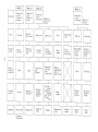
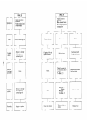
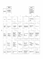
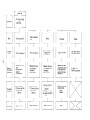
CONTENTS
Title
Section
1.
SPECIFICATIONS
2.
PERFORMANCE
Page
....................................
CURVES
AC Output
..........................................
2
2-2
DC Output
..........................................
3
FEATURES
4.
SERIAL
and SPECIFICATION
5.
SAFETY
PRECAUTIONS
..............................................
NUMBER
LOCATION
................
6
.....................................
7
Fire Prevention
.......................................
7
5-2
Precautions
7
5-3
Other
for Exhaust Gases. .............................
......................................
Precautions
7
...............................
8
COMPONENT
7.
FUNCTION
7-1
7-2
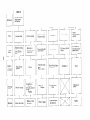
10.
5
5-1
6.
9.
2
2-1
3.
8.
1
..........................................
IDENTIFICATION
OF EACH
COMPONENT
............................
11
12
Generator
...........................................
Engine .............................................
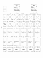
DESCRIPTION
OF MAIN
8-1
Electronic
lgnition
8-2
Generator
Operation
OPERATIONAL
LIMITS
COMPONENTS
System
14
14
................................
OF THE
15
GENERATOR.
9-1
AC Output
..........................................
DC Output
Simultaneous
..........................................
Use the AC/DC Output
Wire Length.
.........................................
MEASURING
.........................
....................................
9-2
9-3
9-4
10-1
10-2
10-3
10-4
11
PROCEDURES
...................
17
17
19
.........................
20
20
..................................
21
21
Meters
.............................................
...................................
Measuring AC Output
...................................
Measuring DC Output
Measuring
Insulation
Resistance
. . .
. .
. . . . . . .
. . . .
. . . .
.
23
23
23
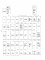
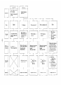
11.
FUNCTIONAL
CHECK
Control
11-2
Stator.....
11-3
Rotor . . . . .
lgnition Coil
Condenser
Rectifier
. .
11-6
.
...
. ..
.
..
. ..
Panel
DISASSEMBLY
AND
Preparation
12-1
12-2
Special
12-3
Disassembly
12-4
Assembly
12-5
Carburetor
OF EACH
.
11-1
11-4
11-5
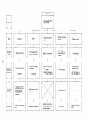
12.
Page
Title
Section
.
. .
.
.
ASSEMBLY
and Precautrons
Sequence
Procedure
TROUBLESHOOTING
14.
CRITERIA
15.
WIRING
16.
MAINTENANCE
TABLE
.
.
.
.
.
.
.
..
Tools for Disassembly
13.
COMPONENT..
.
...
. .
...
..
..
. . . . . . . . . . . . . . . . .
25
......
...
......
. .
......
. . .
......
. .
..... ..
25
27
. . .
30
. . . . . . . . . . . . . . .
31
.
. .
...
..
.
.
.
.
.
. . . . . . . . . . . . . .
..
..
..
.
..
31
32
38
....................................
48
..........................................
. . . .
. . . . .. .
FOR ADJUSTMENT
DIAGRAM
. .
. .
. .
. . .
.
. .
Checks and Maintenance
.
.
. . ..
.
30
31
...............................
and Assembly
....................
...................................
. .
29
29
. . . . . . . . . . . . . . . . . . . .
.
. . .
. . . . . . . . .
. . . . . . .
(every 8 hours)
. . . . . . . .
. .
.. . . . . . . . . . . . . .
. . . .
. .. . . .
. .
16-1
Daily
16-2
16-3
Checks and Maintenance
Checks and Maintenance
for Every 20 Hours
for Every 50 Hours
16-4
Checks and Maintenance
for Every 200 Hours
16-5
16-6
16-7
Checks and Maintenance
for Every 500 Hours (semi-annually)
........
Checks and Maintenance
for Every 1000 Hours (annually)
...........
When the Generator is not used for Prolonged Periods:
.............
. . . .
51
68
71
72
...................
72
....................
(every 10 days)
72
72
(monthly)
.........
............
73
73
73
73
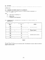
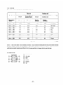
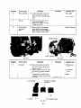
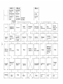
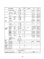
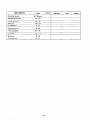
1. SPECIFICATIONS
Model
Engine:
i
R600
Type
Forced air-cooled,
gas01 ine engine
4-stroke,
Displacement
78 cc (4.76 cu.in.1
Fuel tank capacity
2 lit. (0.53 U.S. gal.)
Oil pan capacity
350 cc (0.75 U.S. pints)
side valve,
L--
Ignition
Solid state ignition
system
~~
Starting
Generator:
Recoil starter
system
Rated continuous
operating hours
Approx.
Approx.
Type
2-pole,
Exciting
system
Voltage
system
regulating
Maximum
revolving
field type
Self-exciting
Condenser
output
type
500 w
600 W
Rated output
400 w
500w
AC Frequency
50 Hz
60 Hz
110,
AC Voltage
220,230,24OV
DC output
12V - 100 W (8.3 A)
AC receptacle
Standard:
(special:
DC terminal
Two
Over current
protection
Circuit
Frequency
meter
Pilot light
Dimensions
4 hours (50 Hz)
3.5 hours (60 Hz)
2 ea.
1 ea.)
breaker
Standard
equipment
Standard
equipment
370 x 265 x 345 mm
(14.6 x 10.4 x 13.6 in.)
(L x W x H):
18.5 kg (40.7 Ibs)
Dry weight
-1-
110, 120,220v
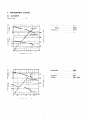
2. PERFORMANCE
2-1
Power
CURVES
AC OUTPUT
Factor
I
. .
.
I
I
I
1 .o
1
!
I
1
I
’
!
1
1
I
I
Output
1 OUTPUT’
Max.
...............
500W
Rated
...............
400W
Frequency.
Voltage.
i
3
w
3
-t
,
//
240
................
..................
50 Hz
220V
FRECiENC
I
i/:
Y
‘1
I
i
I
I
I
1
300
I
t
$
a
CURRENT
50
i
1
I
:
I
:
I
I,
IA)
-
1
,
I
1
/‘\I
I
I
0.51
/
/
/
I
:
1:
CURRENT
I
I
I
I
I
400
2
t
I
300
2.5
...............
500W
Rated
...............
400W
Frequency.
FREQUENCY
I
1
a
,
:
!
Max.
500
I
1.5
(Al
Output
i
-i----l
II
//
0vi
1
, OUTPUT
1.1
j
49-
260
I
0
-
-2-
Voltage
................
...................
50 Hz
230V.
240V
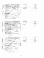
. . . . . . . . . . . . . . . 500W
Rated . . . . . . . . . . . . . . . 400W
Frequency . . . . . . . . . . . . . . . . . 50Hz
Voltage . . . . . . . . . . . . . . . . . . . 11OV
Output Max.
w
U
LL
3
1
-1
w
>
U
1
a
CURRENT ( A )
-
1
-I
N
tI
3
600
61
U
60
w
LL
500
62
U
400
59
-1
3
I-
120
a
110
J
100
0
3
0
17
I-
1
I
300
w
>
1
. . . . . . . . . . . . . . . 600W
Rated . . . . . . . . . . . . . . . 500W
Frequency . . . . . . . . . . . . . . . . . 60 Hz
Voltage . . . . . . . . . . . . . . . . . . . 1 1OV
Output Max.
200
2
100
>
2 0
1
3
CURRENT ( A )
4
0
5
-I
N
600
500
62
3
E
U
U
6
61
400
60
59
300
. . . . . . . . . . . . . . . 600W
Rated . . . . . . . . . . . . . . . 500W
Output Max.
1-
Voltage.
-3
I-
>
2I-
240
200
230
(3
a
5
0
>
3
0
220
100
210
a
0.5
1
1.5
CURRENT ( A )
2
2.5
a
-4
. . . . . . . . . . . . . . . . . 60 HZ
. . . . . . . . . . . . . . . . . . 220V
Frequency
-
600
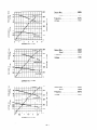
Output
52
51
Max.
...............
500W
Rated
...............
400W
500
Frequency
.................
50 Hz
50
..................
Voltage.
49
400
300
200
0
1
2
CURRENT
3
IA)
4
5
11OV
t
3
+
3
E
2
6
-
1
I I I I I
Output
62
Max.
...............
600W
Rated
...............
500W
Frequency
.................
60 HZ
61
400
60
59
FREQUENCY
300
r
I
200
120
..................
Voltage.
11OV
I
3
f
k
‘0
110
100
100
0
0
1
2
3
CURRENT
IA)
4
5
6
-
Output
Max.
...............
600W
Rated
...............
500W
Frequency
Voltage
0
0.5
1
CURRENT
1.5
2
2.5
(A) -
-4-
.................
...................
60 Hz
220V
3. FEATURES
l
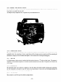
Robin Exhaust Fan Cooling System for low body temperatures, low noise. longer engine life and reliable performance.
l
Large 78cc 4Stroke
l
Simple One-Touch Engine Control Switch with the engine and fuel on/off levers and choke all integrated into one
Engine provides enough power for constant 500W (at 60 Hz) rated output.
switch.
l
Easy and Reliable Starting with pointless ignition. This generator is also a brush-less type generator for maintenance-free
operation.
l
Simple Design for a clean appearance and easy maintenance.
l
Compact and Lightweight with an easy one-hand carrying handle grip. This generator also offers a high power-to-weight
ratio and economical operation.
l
Circuit Breaker Protection for safe operation. Replacement of fuses is not necessary in case of an overload.
l
Unique Dual Output Design so that two separate A.C. and D.C. electrical appliances can be used at the same time.
-5-
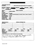
4. SERIAL
and SPECIFICATION
NUMBER
LOCATION
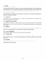
The serial number is stamped on the crankcase at the opposite side of the carburetor.
The specification and specification number are shown on the nameplate located on the rear cover.
Always specify these numbers when inquiring about the eoenerator or ordering parts in order to get correct parts and accurate
service.
SPECIFICATION
SPECIFICATION
NUMBER
SERIAL
Fig. 4-7
-6-
NUMBER
”
-
. . .
-
.
.
-
-
5. SAFETY- PRECAUTIONS
51
FIRE
PREVENTION
1) Keep the generator away from combustible materials during operation. Take special precautions with flammable substances.
2) Do not run the generator in a incline position or while it is slanted at an angle. Avoid moving the generator while it
is in operation to prevent the generator from falling over or leaking fuel.
3)
Do not place a carton or similar object over the generator while the generator is running. If covered, cooling will be
diminished and cause the generator to overheat.
4)
5)
Operate the generator at least lm away from a building or wall.
Be sure to stop the engine before filling fuel into the fuel tank.
If fuel is filled while the engine is running, fuel vapors may rise from the fuel tank resulting in a potential fire hazard.
6)
Fuel used in engine operation is very volatile and highly flammable. Take special precautions not to spill fuel when
filling the fuel tank. If fuel is spilt, wipe it off thoroughly and let dry before starting the engine.
7)
Do not overfill the fuel tank and always be sure to fill iuel only up to the level specified at the fuel supply- port.
8)
Do not smoke or use open flame when filling the fuel tank.
5-2
PRECAUTIONS
for
EXHAUST
GASES
1) Avoid operating the generator in poorly ventilated locations such as an office, warehouse. narrow tunnel. well, hold.
tank. etc.. If the generator is run continuously in such poorly ventilated areas. the operator may suffer carbon monoxide poisoning.
3
5-3
Always operate the generator with the exhaust port directed toward the open air or where good ventilation is assured.
OTHER
PRECAUTtONS
1) To prevent electric shock. do not touch the generator with wet hands. For example, when the generator is used to
drive a submersible pump, be sure to connect the earth cord of the generator to the earth cable of the pump.
2)
Do not splash water over the generator during operation. And also avoid operating the generator in the rain. If the
generator gets wet. it may fail to start or short-circuit. and the operator may possibly receive a severeelectric shock.
3)
Do not connect the generator to existing power lines which have been originally installed as the power supply system
of a building. If connected. the generator will burn out.
4)
Avoid running the generator with its cover removed.
-7-
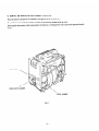
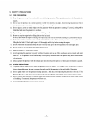
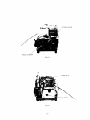
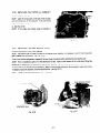
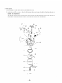
6. COMPONENT
IDENTIFICATION
h’UFFLE9
C 0 V E F1
AlFl
Al=
CLEdYER
CLEALER
CO\.‘ER
Fig. 6- 7
FUEL
T.ANY
GEZERATOS
\*’ ” z FLER
C:O\.‘ER
/
RECOIL
STIRTE?
Fig. 6-3
SPARK
Ffg. 6-4
-9-
PLUG
CAPBLRETOR
Fig. 6-5
#El3 PIPE
AIR \;E’JTl
Fig. 6-6
-
10-
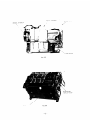
7. FUNCTION
7-1
7-1-1
of EACH COMPONENT
REAR
HOUSING
GENERATOR
RECTIFIER
STATOR
The stator consists of a laminated silicon steel sheet core,
a main coil and condenser coil which are wound in the core
slots.
AC and DC output are taken out from the main coil. (DC
output is taken out from the part of main coil which is in
the middle of the main coil.)
The condenser coil excites the stator field coil which
Fig. 7- 7
generates AC output in the main coil.
7-1-2
CONDENSER
The condenser is mounted on the rear housing and is connected to the condenser coil which is wound in the stator. The
condenser coil magnetizes the rotor which increases the density of magnetic flux.
7-1-3
RECTIFIER
The rectifier is also mounted on the rear housing and it converts AC current output from the main coil to DC current. The
DC output from the diode of this rectifier is connected to the DC terminal.
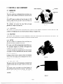
7-1-4
ROTOR
The rotor consists of a lamination silicon steel sheet core
and field coil which is wound over the core.
DC current m the field coil magnetizes the steel sheet core.
Two permanent magnets are provided at 90 degrees from
the poles for the primary exciting action.
A securely mounted fan is pressure-fitted on the end of the
rotor shaft to cool the individual coils. iron cores. rectifier.
and other integral parts.
Cooling air from the fan is drawn in from the ventilation
vents in the rear housing. and is discharged from the ex-
Fig. 7-2
haust port in the front housing.
7-l-5
CONTROL
PANEL
The panel on the front of the housing has a receptacle with
a ground terminal and AC output is taken out with a male
Plug.
The frequency meter is provided to see if the frequency of
generated power shows 50 Hz (or 60 Hz).
DC output is
taken out from the red (positive. +) and black (.negative. -)
terminals.
Fig. 7-3
-11-
7-2
7-2-l
ENGINE
CYLINDER
and CRANKCASE
The cylinder and the crankcase of the engine are of an one-piece aluminum die-cast design. The cast iron cylinder liner is
cast-fitted inside the cylinder.
Both the intake and exhaust ports are positioned at the lateral side of the cylinder and these
ports are formed by using a mold with die-cast cores. The crankcase has its joint face located on the generator side.
7-2-2
The
MAIN
BEARING
COVER
main bearing cover is aluminum die-cast and is mounted on the generator side. By removing the main bearing cover.
the interior of the engine can be inspected.
7-2-3
CRANKSHAFT
The crankshaft is constructed of forged carbon steel. The crankpin is induction-hardened and has a pressure-fitted crank
gear located on the generator side of the engine.
7-2-4
CONNECTING
ROD and PISTON
The connecting rod is constructed of forged aluminum alloy with both the major and minor ends utilized as bearings.
The oil scraper and cap for the major end are cast together. The aluminum alloy casting piston has two compression rings
and one oil ring.
7-2-5
CAMSHAFT
The camshaft is constructed of special cast iron and has intake and exhaust valve drive cams. each of which engageswith the
cam gear. An exclusive aluminum alloy is used on each end of the camshaft in the place of bearings.
7-2-6
VALVE
ARRANGEMENT
The intake valve is installed at the oil port side and the exhaust valve at the generator side.
7-2-7
CYLINDER
HEAD
The cylinder head is die-cast aluminum and has Ricardo type combustion chamber featuring greater volume capacity for
improved combustion efficiency.
For easier spark plug maintenance. the cylinder head is positioned at an angle to allow
greater access.
7-2-8
GOVERNOR
The centrifugal weight type governor ensures constant engine speed, regardless of load fluctuations (the governor is mechanically linked to the governor drive gear).
-12-
7-2-9
EXHAUST
FAN
COOLING
SYSTEM
Instead of blowing outside air on the engine. the Exhaust Fan Cooling System of this generator intakes the cool air and
forces the hot air outside from one outlet.
This keeps the body temperature lower for greater safety and extends service life.
7-2-10
LUBRICATION
SYSTEM
The moving and sliding parts inside the engine are lubricated with the oil scraper fitted on the connecting rod. As the
crankshaft rotates, the connecting rod moves up and down and the oil scraper moves in conjuction with the connecting rod
movements to scrape up oil in the crankcase and splash it over the surfaces of the moving and sliding parts.
7-2-l 1
IGNITION
A flywheeh’magneto ignition system is employed with the ignition timing set at 23” before top dead center. The magneto is
composed of the tl)wheel and ignition coil with the fll-wheel mounted on the rotor shaft. The ignition coil is fitted to the
front housing.
7-2-l 2
CARBURETOR
The horizontal suction type carburetor is adjusted so that the engine will provide excellent starting. good acceleration.
low fuel consumption. and superior output [for details concerning carburetor construction. see the paragraph dealing with
carburetor construction and disassembly/assembly (Page49)]
7-2-13
AIR
CLEANER
The air cleaner is a semi-wet type and contains a sponge element.
- 13-
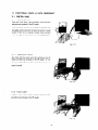
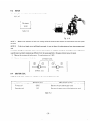
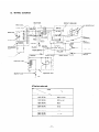
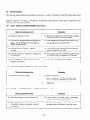
8. DESCRIPTION
8-1
ELECTRONIC
OF MAIN COMPONENTS OPERATION
IGNITION
SYSTEM
(Solid State Ignition
System)
The electronic ignition system features a polver transistor as the current control element. Therefore. the ignition system is
an electronic contact point-free type that operates with the po\ver transistor impulses controlling the current. This system
also called TIC (transistor igniter circuit) is virtually free of ignition failure which generally results from contamination of
the contact points. a typical problem vvrth contact type ignition systems.
Because this ignition system has no contact points. it is not affected by moisture. oil. dust. or other contaminants. 4s a
result. this electronic ignition system ensures sure and positive ignition lvith reduced maintenance.
The TIC mechanism consists of a transistor-mcorporated ignition coil and a permanent magneto built-in flywheel which is
pressure-fitted on the rotor shaft of the generator.
//////
I
IGNITION
IGNITION
TIMING
DETECTING
CIRCUIT
COIL
PLUG
FLYWHEEL
COOLING
FAN
Fig. 8- 1
1) When the permanent magneto built-in flywheel starts rotating. power is generated in the primary coil of the ignition
coil and current tlows to the resistor @ _
From the resistor, current flows to the power transistor. RYth this current. the power transistor turns on. releasing
current I(@ Thrs stage corresponds to the closmg of contact points.
2)
As the tlywheel comes to the point of ignition. the ignition timing detecting circuit is activated while the current @
is flowing through the circuit.
When the ignition timing detecting circuit is activated. the signal transmitter transistor actuates hzith current 8 flowing. \Vhen current ,$$ starts flovving. current s flowing through the power transistor is cut quickly. As a result. high
voltage is produced in the secondary coil and this voltage is applied simultaneously to the spark plug which ignites for
ignition. This stage corresponds to the opening of contact points.
-14
-
c
8-2
GENERATOR
.I
OPERATION
INITIAL
EXCITATION
PERMANENT
MAGNETO
FIELD
COIL
ROTOR
STATOR
i
:
I
RECEPTACLE
RESIS
-----
DIODE
MAIN
COIL
CONDENSER
COIL
CONDENSER
L ------
A
Fig. 8-2
8-2-l
1)
GENERATION
of NO-LOAD
VOLTAGE
When the generator starts turning the permanent magneto built-in to the flywheel generates@ 1 to 2\’ of AC voltage
in the main coil and also generates 1 to 4 of AC voltage in the condenser coil.
2)
The capacitor coil is connected to a capacitor so when a voltage is applied to the condenser coil. minimun current
@ flows in the condenser coil. At this time, minimum flus is produced. vvith which the magnetic force of the rotor’s
magnetic pole is intensified.
When this magnetic force is intensified. the respective voltages in the main coil and
condenser coil rise. Current 1s flowing in the condenser coil increases. with the magnetic tlux densit)- of the rotor’s
magnetic pole increasing further.
Also. the main coil voltage and condenser coil voltage increases. These voltages
continue rising as this process is repeated.
3)
As current flows in the condenser coil. the magnetic flux density changes. DC voltage is induced in the field coil when
the magnetic flus density varies. Successively. DC current is rectified bl the rectifiers connected to both ends of the
field coil. and DC current @ flows in the field circuit. With this current. the rotor core is magnetized. allowing the
generator to output steady voltage.
41
When generator speed reaches 2000 to 2300 rpm (50 Hz specification) or 3000 to 3300 rpm (60 Hz specification). the
current in the condenser coil and field coil increases sudden&. This acts to stabilize the respective coil output voltages.
If generator speed further rises to the rated v-alue.the generator output voltage will reach the rated value.
8-2-2
VOLTAGE
FLUCTUATIONS
UNDER
LOAD
When load current -s flows from the electric equipment to the generator. the magnetic flux which is produced as current
.s flows in the main coil. this serves to increase current ‘$ flowing in the capacitor coil. With current @increased. the
magnetic flux density across the rotor core rises. As a result. the current flowing in the field coil increases, and the generator output voltage is prevented from decreasing.
-15-
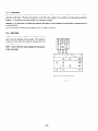
8-2-3
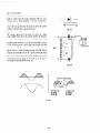
DC OUTPUT
DC output is taken out from the main coil and is fed to the
diode at which time the output undergoes full-wave rectification prior to being supplied to the load connected to
the generator. The diode rectifier works to allow the current to tlow in @ direction but does not allow the current
to flow in s direction as shown in Fig. S-3.
Fig. 8-3
Fig. 84 shows the DC output circuit of the generator.
DC voltage is generated in the main coil; when the voltage
Dl
+
in A is higher than that in C. current !~flows in the direction shown in the figure while no current flows between C
and B because current is cut off by the diode D2. Contraq
to the aforementioned, if the voltage in C is higher than that
in A, current a
flows in the direction as sholvn in the
MAIN
COIL
B
figure. with no current flowing between A and B. This is
because the diode Dl cuts off the current between A and B.
As a result. voltage generated between the DC terminals has
a waveform with t\vo peaks in one cycle. as in the case of
the output waveform shown in Fig. 8-5.
Fig. 8-4
BETWEEN
A
AND
B
OUTPUT
BETWEEN
C AND
WAVEFORM
B
CURRENT
FLOWING
BETWEEN
AAND
B
=w=
Fig. 8-5
- 16 -
0
CURRENT
FLOWING
BETWEEN
CAND
B
@
9. OPERATIONAL
9-1
AC
LIMITS
OF THE GENERATOR
OUTPUT:
Electric appliances normally have rating labels, showing the rated voltage. frequency. power consumption (input power).
and other listings.
The input power specified on such labels is what is required to drive the appliance.
When an appliance is to be connected to the generator. the power factor. starting current. and other factors of the appliance must be taken into account.
9-l-l
NET
RESISTANCE
LOAD:
Incandescent lamps. electric heaters, etc.. can be run off the generator if its capacity matches the total of the respective
appliances. Each of these appliances normally have a power factor of 1.O.
Example :
9-l-2
This generator can provide enough power to operate five 1OOWincandescent lamps.
ELECTRIC
APPLIANCES
WITH
A POWER
FACTOR
LESS
THAN
1.0:
Fluorescent lamps and mercury lamps normally have a low po\ver factor. Therefore. the generator is required to generate
approximately 1.2 to 2 times the power consumed by each load appliance.
Example:
9-l-3
With this generator. three to five 8OW mercury lamps can be operated.
MOTOR
LOAD:
Generally. motors require a large starting current every time they are started. Therefore. when the generator is used to run
a motor, the greatest motor starting load is applied.
The rates of power supply which the generator is required to produce for motor loads. are categorized into two sections.
depending on the types of motor and load conditions at time of starting.
1) Motors (mainly rectifier motors) used for electric drills and similar devices:
Sormally, the motors used for electric drills and similar appliances require the generator to produce approximateI>- I.1
to 3 times the power consumed at time of starting.
Example:
To drive a 2OOWelectric drill. a generator with capacity of about 300 to 600W is necessary.
2) Motors (mainly induction motors) used for pumps and compressors:
Pump and compressor drive motors require the generator to produce 3 to 5 times the power consumed when they are
running. at time of starting. This is because these motors have loads w-hen the>- start.
Example:
To drive a 2OOWsubmersible pump. a generator with a capacity of approximately 600 to IOOOWis necessary.
-17
-
9-l-4
IN THE
SITUATION
THAT
POWER
CONSUMPTION
IS NOT SHOWN
ON THE
RATING
PANEL:
Occasionally. the rating panel of an electric appliance does not carry its power consumption but only shows the mechanical
equivalent to the power consumption.
involved.
In such a situation. it is necessary to calculate the power consumption of the device
Depending on the types of load. the calculated power consumption is adjusted according to paragraphs 9-l-l
through 9-I-3 above.
(Power consumption) = (Mechanical equivalent of device) + (Efficiency)
Efficiency
0.6 - 0.8
Motors:
Fluorescent lamps: 0.7 - 0.8
Example : A 4OW fluorescent
lamp with a lighting output of 40W and assuming that the power consumption of this lamp is
0.7, the power consumption is calculated as follows:
40 + 0.7 = 57W
Further, as per paragraph 9-l-2, the said power consumption is multiplied by a factor of 1.2 to 2. producing a
power consumption of 70 to 11SW. Therefore. with this generator, four to seven 40W fluorescent lamps can be
used.
Example:
In the case of a 2OOWmotor. the mechanical equivalent of the motor is 200W. Assuming that the efficiency of
the motor is 0.7. the power consumption is calculated as 200 f 0.7 = 285W. Similar to the above, the calculated
power consumption is then multiplied as per paragraphs 3-1) or 3-2). taking into account the types of motor
and starting conditions. The table below shows the range of loads applicable to this generator.
Range of workable loads
Electric devices
60 Hz
50 Hz
I
Incandescent
lamp, electric
Fluorescent
lamp, mercury
heater,
etc.
up to 5oow
up to 4oow
lamp, etc.
I
Up to approx.
300W
Up to approx.
400W
Up to approx.
300W
Up to approx.
350W
Up to approx.
150W
Up to approx.
200W
I
I
Motor-driven
tools etc.
Pump and compressor
drive motors
I
/
Table 9- 7
NOTE
7: With motor-driven
and 9-l-4,
the generators
respective
appliance.
supply
to the motor
consumption
Therefore,
NOTE
tools and the motor-driven
pumps
of the said capacities
Once the motor
decreases
thereafter
and compressors
are required
has started,
only
the power
in paragraphs
9-7-3
the motors
of the
when starting
which
to a level approximately
specified
the generator
1.2 to 2 times
is required
to
the rated power
.
the surplus
2: As for
the motor-driven
starting
varies according
capacity
of the generator
devices
specified
may be used for other electric
in paragraph
to the types of motor
9- 7-3 and 9-l -4, the power
and the load conditions
- 18-
appliances.
requirement
at time of starting.
for
9-2
DC OUTPUT
When the generator is employed to recharge batteries. care must be exercised about the specific gravity of electrolk-te rn
each batter\. case.
9-2-l
MEASURING
THE
SPECIFIC
GRAVITY
OF
ELECTROLYTE:
The specific gravity changes with temperature; therefore. it is converted to another corresponding to 20°C.
S20 = St + 0.0007 (t - 10)
where
S~J = Specific gravity corresponding to 20°C
SI
t
9-2-2
= Measured value
= Temperature at time of measurement
REMAINING
CAPACITY
ELECTROLYTE:
c
ESTIMATED
WITH
REFERENCE
I
Specific gravity
(20°C)
Remaining battery
(%I
1.260
100
1.240
87
1.220
75
1.200
62
1.180
50
1.160
37
1.140
25
TO
THE
SPECIFIC
GRAVITY
OF
I
Remarks
I
I
Good charged condition
I
Charging
is necessary.
,
Immediate
charging
is necessary.
Table 9-2
9-2-3
BATTERY
CAPACITY:
The battery capacity is expressed in units of ampere-hour (AH). One AH stands for the capacity capable of providing one
ampere of current for one hour.
-19-
9-3
SIMULTANEOUS
USE THE
AC/DC
OUTPUT
If you use the AC’DC output simultaneously in this generator, be careful not to exceed the total power consumption.
50 Hz
below 3OOW
Hz
below 3OOIV
60
NOTE:
9-4
Max. output
WIRE
of DC is 1OOW /12V x 8.3A).
LENGTH
When long Lvires are used between the generator and a load, the resistance of each wire increases and a voltage drop occurs.
Consequently. the input voltage to the load declines and occasionall!- damages the load.
Exercise caution Lvhen deciding on wire length. For reference. the table below shows the voltage decreasesthat occur in
100 m (300 ftt) long wires with different cross sectional areas and varied resistances.
Cross
sectional
area
mm’
Allowable
current
A
0.75
7
1.25
No. of conductorsl
conductor
diameter
No./mm
Resistance
,0,/l
OOm
Current
1A
’ 3A
5A
8A
30/O. 18
2.477
2.5U
8U
12.5U
-
12
5OiO.18
1.486
l.5U
5u
7.5u
l2U
2.0
17
3710.26
0,952
3u
5U
3.5
23
4510.32
0.517
-
1.5U
5.5
35
7OiO.32
0.332
-
1U
1u
Table 9-3
- 20 -
’
’ 10A
12A
‘I
15u
8U
1 1ou
2.5U
’ 4U
5U
2U
: 2.5U
L
3.5u
-
;-:
18U
I
; l2U
I
15A
6.5U
; 4u
I
15u
- 7.5U
5u
:
, 8
t
0”
8
; <
>
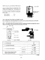
10. MEASURING
PROCEDURES
AC
10-l
10-1-l
DC VOLTMETER
VOLTMETER
METERS
VOLTMETERS
Both AC and DC voltmeters are nesessar! .
The approximate AC voltage ranges of the voltmeters to be
used for various types of generators are as follows:
0 to 1SOV: Type with an output voltage of 110 or
12ov
0 to 300V: Type with an output voltage of 220.230
or 21OV
Fig. 70-l
10-l-2
AMMETER
AC
Both AC and DC ammeters are necessary.
AMMETER
DC AMMETER
The AC ammeter must have a scale range from 0 to approximately 10A.
The DC ammeter must have a scale range from 0 to approximately 15A.
Fig. 10-2
10-l-3
FREQUENCY
METER
The frequency meter must have a scale range from 45 to approximately 65 Hz.
NOTE:
Note
the range of input
voltage
of the frequency
meter.
Fig. 70-3
-2l-
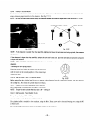
10-l-4
CIRCUIT
TESTER
A circuit tester is used for measuring resistances and others.
Fig. 104
10-l-5
MEGGER
TESTER
To measure the insulation resistance of the generator. Use
voltage capacity of 5OOV.
Fig. 10-5
10-l-6
TACHOMETER
Use the contact-less tl pe tachometer.
Fig. 10-6
- 22 -
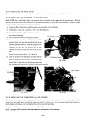
10-2
MEASURING
AC OUTPUT
SWlTFf;
TOACd+)@
LOAj
km77
With the circuit shown in Fig.lO-7.measurement 1smade of the AC output of the generator. An electric heater or an incandescent lamp with a power factor of 1.O is suitable as a load for the generator.
When the measured AC output of the generator is confirmed to be wnhin the voltage range specified in the table belon.
over its voltage rating. the AC output is normal.
Measurement must be made under rated load and at rated speed; sometimes. load and speed adjustments are necessary-.
Voltage
rating
12ou
11ou
Range of
voltage
108% 12OU
118-
I
130U
220u
230,240U
218 - 240U
235 - 260U
Table 10-l
10-3
MEASURING
DC OUTPUT
SWITCH
DC TERMINAL
Fig. 10-8
Measurement is made of the DC output of the generator with the witch shown in the abobe circuit turned on while the
generator is kept running at its rated speed. The DC output should be aithin 1 1 to 14V. Lvith the current regulated at 8.3A
by adjusting the load connected to the generator.
NOTE:
If a battery
Therefore,
IO-4
carefully
is connected
as a load to the generator,
observe the electrolyte
MEASURING
INSULATION
the DC output
level and do not to overcharge
voltage
will increase by approximately
the battery.
RESISTANCE
To measure insulation resistance. connect the megger tester
across either one of the two output terminals of the socket
and the earth terminal.
When the measured insulation
resistance of the generator is over lMI2. it is normal (over
1OMR at time of shipment).
(Be sure to turn on the circuit breaker when measuring
insulation resistance.)
If the insulation resistance is less than 1X19. drsassemble
the generator. and measure the respective resistancesof the
stator.
rotor and control panel.
Fig. 10-9
- 23 -
1 to 2V.
10-4-1
STATOR
Measure the resistances betlveen red coupler leading from
the stator and the core.
Fig. lo-10
1O-4-2
ROTOR
d
Measure the insulation resistance across one of the soldered
terminals of the rotor and the core.
Fig. 10-11
10-4-3
CONTROL
PANEL
Measure the insulation resistances between the live parts
and the grounded part.
If the measured resistance of a component is below 1MR.
the insulation is defective.
Promptly replace the defective component because there
may be leakage of current from the generator and a poten-
_
tial danger of electrical shock.
Fig. 10-12
- 24 -
--
11. FUNCTIONAL
11-l
11-l-l
CHECK of EACH COMPONENT
CONTROL
PANEL
ENGINE
SWITCH
Using the circuit tester. check continuity across the black
and green top terminals of the 6P coupler.
When continuity between the termmals is confirmed with
the engine switch turn2d off. the switch is normal. It is also
normal if there is no continuity between thrse terminals,
when the engine switch is set at RUN or CHOKE position.
Fig. 11-l
1 l-l-2
FREQUENCY
METER
Also check with the circuit tester. th2 continuity across the
yellow and blue top tsrminals of the 6P coupler. If continuity is confirmed between these terminals. the frequency
meter is normal.
Fig. 7 l-2
11-1-3
PILOT
LIGHT
Using the circuit tester, check continuity between the red
and yellow top terminals of the 6P coupler.
Fig. 1 l-3
- 25 -
11-1-4
AC
RECEPTACLES
Using the circuit tester. check continuity between the t\vo terminals at the rear of the XC receptacles while the receptacle is
mounted on the control panel. When continuity is confirmed between the output terminals of the receptacle Lvvltha \vtre
connected across these terminals. the AC receptacle is normal. When the wire is removed and no continuity- is eonfirmed
between these terminals. the receptacles are also normal.
Fig. 7 7-4(A)
11-1-5
Fig. 1 l-4(81
DC TERMINALS
Csmg the circuit tester. check continuity between the DC
terminals at the rear side of the control panel while they are
mounted on the panel.
Ben
continuity- is confirmed bet\veen the DC terminals
Lvith a wire connected across these terminals. the DC
terminals are normal.
continuity
When the wire is removed and no
is <onfirmed
between these terminals. the
terminals are also normal.
Fig. 1 l-5
11-1-6
CIRCUIT
BREAKER
Check continuity between each of two terminals at the rear of the circuit breaker while it is mounted on the control panel.
Normally. there is continuity between each of the two lvhen the circuit breaker is on while there is no continuiq when the
circuit breaker is ofi.
16P coupler
wiring]
DARK
BLUE
YELLOW
RED
BLACK
BROWN
WHITE
Fig. 11-6
- 26 -
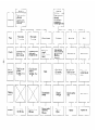
11-2
STATOR
Measure the resistance of each stator coil using the circuit tester.
I
Main coil
:
!
Classified coil
For use with the
frequency meter
AC coil
I
I
DC coil
/
I
:
Condenser coil
I
Cord color of @
Condenser coil
I
Measurement
location
6P coupler
j
6P coupler
Rectifier
connector
50Hz-110V
3.4R
’
0.2251
1.1n
60Hz-110V
2.6
I
0.16
0.9
3.3
j
0.22
50Hz-120V
j
2.7
60Hz-120V
’
I
,
0.16
7.6
0.9
7.6
1.1
8.9
60 Hz - 220V
11.4
0.16
50 Hz - 230V
15.2
0.22
1.1
50 Hz - 240V
15.2
0.22
1.1
0.9
,
:
8.9R
8.9
0.22
!
Between
connectors
1.1
13.9
50 Hz - 220V
1
j
I
I
I
i
1
I
:
7.6
8.9
White/Green
White/Red
I
8.9
j
:
Brown
Blue
Gray
Pink
i
Orange
Orange
I
(at 21cC)
Table 11-l
NOTE:
If the circuit
Erroneous
readings
performed
at ambient
tester is not sufficient/y
will also occur
temperatures
accurate,
it may not show the values given and may give erroneous
when there is a wide variation
different
from
of resistance
the values specified
[6P coupler wiring]
DARK
BLUE
YELLOW
RED
BLACK
BROWN
- 27 -
among coil windings
in the space directly
upper
readings.
or when measurement
the table.
is
FL?. 7 l-7
Fig. 1 l-8
Fi:g. 1 l-9
Fig. 11-10
-28
Table 1 l-2
Fig. 11-11
NOTE
1:
Measure
the resistance
2:
If the circuit
of each coil
winding
while the diode and each resistor
are disconnected
with the/r solder
removed.
NOTE
tester is not sufficiently
accurate,
it may not show
the values given and may give erroneous
read-
mngs.
Erroneous
is performed
-eadings
will also occur
at ambient
temperatures
when
there
different
[APPROX
11-4
IGNITION
is a wide variation
from
of resrstance
the values specified
162:
among
coil
windings
in the space directly
below
or v/hen measurement
the table.
I
COIL
Resistance value
Measurement location
0.61’1
B~tl::ee?
The con-e and
7.52
Betkseen
the grew
Table 7 7-3
-
29 -
cord
the
gree?
and
the
cord
high-ttvsor
cord
11-5
CONDENSER
Measurement of capacity substitutes for checking the condenser. The capacity of the condenser cannot be measured by
using the circuit tester. Therefore. the generator is run with a new condenser to see whether or not the generator performs
normally. If the generator performs normall>-. the condenser is normal.
Reference:
If an instrument
ii available
for measuring
the capacity
of the condenser,
the total capacity
range should
be 70
to 7 7pF fat 20°C).
When the condenser
11-6
displays
its total capacity
within
this range, it is normal.
RECTIFIER
Using the circuit tester. measure the resistance between
each of the two terminals of the rectifier.
The rectifier is
considered normal when the respective resistances have the
values specified below.
NOTE:
Each of the given
of the circuit
values changes with the polarity
tester.
Green
White@
Red
01
@
\
The polarity
3
:...16RI
. . .160
#3
,
Y
of the circuit
Table 7 l-4
-30-
[
tester
1
-
12. DISASSEMBLY
12-1
PREPARATION
*-
and ASSEMBLY
and PRECAUTIONS
1) Be sure to remember the locations of individual parts when disassembling the generator so that the generator can be
reassembled correctly. Tie tags noted with the necessary information to facilitate easier and smoother reassembly.
2)
For more convenience, divide the parts into several groups and store them in boxes.
3)
To prevent bolts and nuts from being misplaced or installed incorrectly. place them temporarily back at their original
positions.
4)
Handle disassembled parts with care; clean them before reassembly using a neutral cleansing fluid.
5) Us2 all disassembly/assembly tools properly, and use the right tool for each specific job.
12-2
SPECIAL
TOOLS
for DISASSEMBLY
and ASSEMBLY
b\o
3
(D
-
Fig. 12- 1
1
No.
Tool No.
;
Name of tool
,
Description
1
2309500107
Valve spring retainer
For disassembling and assembling
and exhaust valves
2
2309500207
Valve guide puller
To pull out the valve guide
3
3589500107
Rotor
To pull out the rotor
:
puller
Table 12-l
-31-
the intake
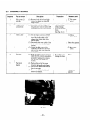
12-3
DISASSEMBLY
SEQUENCE
I
Sequence
Part to remove
1
Side cover (Lj
and (Rj
-I
3
I
I
Couplsrs (disconnection)
I
(1 j Remove both the left and right
co\-2rs. by taking out eight 31-C
flang2 screws.
1 (1) Disconnect th2 (6Pj coupler of
the generator from the other (6P)
extending from the control panel.
’ Choke cab12
II
!
4
Fuel line
I
5
’ Fuel tank
handle
I
Precautions
Description
(1) Set the engine control to STOP.
and remove the screw from the
tip of the choke cable to disconnect the choke cable from
the dial plate.
(2)
Disconnect the outer cable of the
choke cable from the fuel tank
bracket.
(3) Loosen the M4 screw of the
carburetor choke lever swivel to
pull out the inner Loire from the
choke cable.
(1) Hold thz fuel line clamp inserted
inside the felt strainer using pliers,
and pull it backward to remove
the fu21 line from inside the
strainsr.
(1) Push up the end of the cover
fitted to the handle with finger.
I
r (2) Pull out the rubber tube use; as
the air vent pipe.
a (3) Remove two bolts (tank). and
remove the handle.
Fig. 12-2
-32-
I
Necessary tools
2
!
PlUj screwdriver
Pull them under
while pressing
1 down the retainer
claws.
!
622 Fig. 1Z-2.)
rs Minus
screw-driver
I
1 1Omm box spanner
13 Plus screwdriver
/
’
Be careful not to
Pliers
damage the hose. :
I
I
1Omm box
I spanner
Part to remove
Sequence
6
8
( 1) Remove the rear :over at the
opposing sid2 of the control
pan21by unscrewing th2 four
$16 flange bolts.
1Omm box
spannsr
Fuel tank
(.I) Loosen the set screw of th2
strainer shaft at th2 rear of the
engine control switch.
(2) Remove two M5 flange bolts
clamping the front cover and
tank bracket together. and tank
bracket together. and then
remove the fuel tank.
,z Plus screwdriver
Front cover
(.l j Rsmove two MS tlange bolts
clamping the front cover to
the basr to rrmove the front
cover.
Fuel hose
(1) Using pliers. hold the fuel line
clamp at the fuel support joint
of the carburetor (L-joint
directed downward) to pull it
aside. Then. pull out the line.
,
9
Necessary tools
Rear cover
I
7
Precautions
Description
I
10
Choke cable
11
I Muffler cover
and muffler
! 1Omm box
spanner
1Omm box
spanner
Be careful not
to damage the
’ fuel line.
Electricians’
! pliers
(1 j Insert the tip of a screwdriver
(.tlat-headed type) in the groove
of the choke cable bracket protruding from the head cover.
!
I
, (,SeeFig. 1Z-3.)
(1) Remove the out2r cover; this is
done by removing seven M5
tapping screws.
(2) R2move one M6 x 1’ flange
bolt of the muffler bracket. and
two M6 nuts from the muffler
tlange. Then. remov2 th2 flange.
(3) Remove four 315 x 8 lock screws
from inside the muffler t I remove
the inner cover.
3
Take care not to
-3 Plus screwdrop the removed
driver
screws down into
the cooling air
! IOmm box
1 channel.
spanner
’ (See Fig. 11.4.)
3 Minus screwdriver
I
flUFFI
Fig. 124
Fig. 123
- 33 -
Minus
screwdriver
Sequence
12
13
(1) Remove one set screw of the
earth wire which grounds the
rear housing and base plate
togethsr (Zr)OV system onlv).
(2) Rsmove four 5115x 10 bolts from
under the base plate.
Bas2 platz
(1) Remove the recoil starter from
the rear housing. by removing
three 516 x 8 flange bolts.
Recoil starter
Starter pullek
I
I
I
(1 j Turn the starter pulley b]- hand
to set the piston to the compression stroke limit (lvhere the pulle)
becomes heavy). Csing a hammer
strike the box wrench set ov2r the
head of the through bolt to remove
the bolt. Then remove the pulleb _
Fig. 12-5
Sequence
Necessary tools
Precautions
Description
1 Part to remove
; uT Plus screwdriver
I
I
j
Smm box spanner
1Omm box
spanner
(See Fig. 12-S.)
1?mm box
spanner
Handle hammer
(See Fig. 1Z-6.)
Fig. 12-6
Part to remove
Description
Precautions
,
Necessary tools
I
15
Stator assemblq-
I
1
I
I
/
(1 j Remove three M6 x 85 bolts
clamping the rear housing of the
stator assembly. and the front
housing together.
(2j Remove the stator assembly-from
the front housing. The stator and
rear housing are removed together
by using a plastic hammer to light11
strike the boss of the rzar housing.
(See Fig. 12-7.)
(3) Remove the lead from the clamp
. . b_~-taking out. one M4 x 8 scre\v.
(4) Kemove both the capacitor and
I
diode from the rear housing by
removing three M5 x 30 scre\\s.
(5) Remove the wiring between the
i
stator and rear housing. Disconnest three terminals irom the
diode. t\vo terminals from the
capacitor. and the ground \vire
from the r2ar housing.
-34 -
’
1Omm box
spanner
Plastic hammer
j
3 Plus screw_ driver
: Cd Plus screwdriver
Part to remove
Sequence
16
Description
’ Rotor assembl)
Precautions
(1) Fit the rotor puller to th2 rotor
shaft. and drive it into place to
remove the rotor from the engine
shaft.
1;
Plug cap
(1 j Remove the plug cap from th2
spark plug in advance.
(3) Remove the clamp of the highvoltage power cable.
18
Front housing
and center
baffle
(1 j Remove the front housing and
center baffle from the engine
main bearing. b) removmg thrze
M6 x Xmm bolts and one M5
x 55mm bolt.
!
Necessary tools
’ Rotor puller
Plastic hammer
1Omm box spanner
I
j
(See Fig. 11.8.)
CENTER
t
BAFFL
FRO
Fig. 12-7
Part to remove
Sequence
19
Fig. 128
!
Precautions
Description
~
Air cleaner
(1) Remove the center screw of the
air cleaner cover to remove the
cleaner cover. filter element. and
element retainer.
(2) Remove the M5 screw at the lower
right inside the element chamber.
(3) Remove tvvo M6 flange nuts
clamping the air cleaner and the
carburetor together to remove the
air cleaner.
AIR
CLEANER
ELEMENT
RETAINER
*
ELEMEN/T
?
FIQ. 10-9
-35-
i? ;s Minus screw-
driver
A
\fi Plus screwdriver
i 1Omm box
spanner
! (See Fig. 12-9.)
& ELEMENT
Al R ‘CLEANER
Necessary tools
COVER
I
Part to remove
Description
Precautions
20
Governor and
related parts
(.1) Remove the governor lever from
the governor shaft.
(~j Remove the governor rod, rod
spring. and governor spring.
Loosen the bolt
(unnecessary to
remove it)
‘1
Carburetor
(1 j Remove the carburetor from
the stud area of the intake side
flange of the crankcase.
7-3
--
Head cover
Sequence
,
I
/
I
Necessary tools
1Omm box spanner
I
(1 j Remove two M5 screws from the
lateral side of the head cover to
remove the head cover.
.B Plus screwdriver
i 1Omm box
5 anner
+
5 Plus screwdriver
33
Qlinder baffle
(1 j Remove the M6 bolt from the
crankcase and the $15 bolt from
the main bearing cover to remove
!he cylinder baffle.
24
Spark plug
(1) Remove the spark plug from the
cylinder head.
:
19mm box
spanner
25
Cylinder head
(1 j Remove sev2n M6 x 32 bolts to
remove the cl-linder head.
(3) Remove the head gasket.
; Mark the head
gasket with its
mounting position
accurately matching the cylinder
head, also mark
the gasket mounting face of the
, cylinder head.
1Omm box
spanner
(1) Remove both the inner and outer
tappet chamber covers from the
crankcase. by removing two Y6
x 1: bolts.
(3) Remove both the intake and
exhaust valves.
(3) Remove the valve spring and
retainer.
B2 sure to position the notch in
the spring retainer’s outside periphery to the front
and hook the
minus screwi driver (medium
side) in the recess
/ (lower side) of
a the retainer.
Then pull the
spring retainer
backward to remove it.
t 1Omm box
spanner
i Intake valve
:
I
I
I@
1
PULL
(1) Remove the Woodruff key from
the crankshaft.
(2) Remove five M6 x 15 bolts locking
the main bearing cover from the
crankcase.
(3) Using a plastic hammer or a
similar tool. strike the mam
bearing cover uniformly around
its peripheq to remov-ethe cover.
-36 -
13 Minus screwdriver
I
I
’
RETAINER
BACK
1Omm box
spanner
’ Plastic hammer
Be careful not
to damage the
i lip of the oil seal.
;
Sequence
Part to remove
Description
28
’ Camshaft
(1) Pull out the camshaft from the
crankcase.
29
; Tappets
I
(1 j Remove the tappets from the
crankcase.
II
Connecting rod !
and piston
I
I
Piston and
piston rings
31
I
32
Crankshaft
(1 j Pull out the crankshaft from the
crankcase. If unable to pull it out
by hand, use a plastic hammer to
gently strike the main bearing
joint tace. and pull the crankshaft
pulled out.
33
Governor shaft
(1) Remove the clip of the governor
shaft. and pull out the governor
shaft from the crankcase.
I
I
Be sure to mark
the tappets to
distinguish them
from each other;
one for the intake
valve and the
other for the
exhaust valve.
i Confirm the
(1) Scrape off the carbon deposits
from the cylinder and piston head. , mounting direcPush open the bend of the connecttion of the oil
ing rod lock washer, and remove
scraper.
two bolts.
(2) Remove the lock washer and connetting rod cap from the crankshaft.
(3) Turn the crankshaft until the
piston comes to its top position.
and push the piston from the
upper part of the cylinder.
(1) Remove two clips from the piston
pin and take out the piston pin.
Remove the piston from the
connecting rod.
(2) Each of the piston rings can be
removed from the piston by opening wide the ring joint.
-37-
Necessary tools
Set the crankcase
sideways so that
it will not fall
i and damage the
! tappets.
,
;
i
1
30
Precautions
(1) Replace
these clips
vvith new
ones: do not
reuse them.
: (2) Be careful
not to
damage the
1
minor rod
end.
(3) Be careful
not to open
the ring
joint excessivelv .
!
!
1 e Minus screwi
driver
Pliers
1Omm box
spanner
;
I
I
I
12-4
ASSEMBLY
PROCEDURE
0 Precautions in Assembly
1) Thoroughly clean each part. When cleaning. take special care for the piston. cylinder, crankshaft, connecting rod, and
bearings.
7)
Be
sure to completely remove the carbon deposits on the cylinder head and piston head. Also, thoroughly clean and
remove carbon deposits from each piston ring groove.
3)
Apply lubricating oil to the lip of each seal. Confirm that the lip of each oil seal is not damaged. If damaged, replace
with new one.
4)
Replace the gaskets and similar items with new ones; do not reuse old gaskets.
5)
Replace the keys. pins, bolts, nuts. etc., with new ones if necessary.
6)
Do not apply torque exceeding the specified value.
7)
Apply lubricating oil to both moving and sliding parts when they are assembled.
8)
Prior to assembly, check the clearance of each part, and adjust it if necessary.
9)
When each of the main components are assembled, turn it by hand to check for smoothness of rotation and unusual
noise.
l
Assembly Sequence and Precautions
12-4-l
GOVERNOR
SHAFT
Put the governor shaft into crankcase, then drive the clip into position to secure the governor shaft.
124-2
CRANKSHAFT
1) Insert the crankshaft into the ball bearings of the crankcase.
2)
Fig. 104-l shows the dimentional tolerance of the crankpin.
OUTSI DE
-DIAMETER
Fig. 72-10
-38-
l
Tolerances of Newly Installed Parts
Thrust
directional
tolerance
between
the cylinder
and piston
skirt
I
!
Top ring
Clearance
of piston
Second
ring joint
I
ring
0.008L
0.2L
- 0.047L
- 0.4L
0.2L - 0.4L
Spare rings
’
Oil ring
!
Top ring
Clearance
between
piston
ring
Second
ring
1
I
Oil ring
outslde diameter
between
connecting
Clearance
between
piston
1
0.09OL
- 0.135L
0.06OL
- 0.105L
Spare rings
,
0.037 L - 0.063L
I
Side clearance
Clearance
- 0.25L
O.OlOL-0.065L
Inside and
clearance
Clearance between connecting
rod major end and crankpin
0.05L
rod minor
pin and piston
0.1 L - 0.7L
end and piston
pin
O.OlOL - 0.029L
pin hole
0.009T
- 0.01 OL
L = Loose
T = Tight
Table 12-2
NOTE:
The clearance
cylinder
124-3
between
the piston
and cylinder
is checked
by measuring
the clearance
between
skirt.
PISTON
and
PISTON
RINGS
OPEN ENDS OF
PISTON
RINGS
1) If a ring expander is not available. set the ring joint at
the first land of the piston. as shown in Fig. 12-l 1 so
that the ring can be slided into its groove.
NOTE:
Be careful
sively
each ring.
piston,
followed
The top
marked
not
to twist
or expand
The oil ring is fitted
first
exces-
on to the
by the second ring and top ring-
and second
rings must
be fitted
with
their
sides kept upward.
Fig. 12-l 1
~j
the piston
The connecting rod is joined to the piston by the piston pin.
NOTE:
Before assembly,
apply
sufficient
lubricating
oil to the connecting
NO JE:
Be sure to fit the clips to both sides of the piston
-39-
pin.
rod minor
end
and
STD EQUIPMENT
-
Top ring
!
’ Taper
SPARE PARTS
Taper
I
\
Second
ring
Taper
Undercut
‘\
. \ ‘,\
x.
:.
q \ ..
\
Oil ring
I
Fig. 72-72
1244
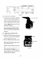
INSTALLING
THE
CRANKCASE
1) The connecting rod is put into the cylinder while
GUIDE
holding it with the piston ring guide. as shown in Fig.
lo-13 (in the case that a piston ring guide is not
available, press rings inward with fingers and at the
same time. strike down the piston. using a wooden
block).
The connecting rod must be mounted in
place with its @ and MA marks directed to the ball
bearing side of the crankcase.
NOTE:
piston
Apply
rings, connecting
NOTE:
the piston
adjacent
12-4-5
1j
a sufficient
The top,
quantity
of
rod surfaces,
second
oil
to
and cylinder.
and oil rings are fitted
with their ring joints
the
arranged
to
Fig. 72-73
90’ off each
joint.
INSTALLING
MAJOR
END
THE
CAP
CONNECTING
ROD
Manually turn the crankshaft until the piston reaches
top dead center. Gently strike down the piston head
until the connecting rod touches the crankpin to
install the connecting rod major end cap.
3)
The cap is installed with the 011scraper positioned
right-downward. (See Fig. 13-14.)
NOTE:
fully
OIL SCIRAPER
Be sure to use a new lock
washer;
and care-
bend the washer correctly.
NOTE:
crankshaft
When
the
cap has been
to see if the connecting
installed,
turn
the
rod moves smooth-
Iv.
NOTE:
The correct
torque
for installing
ing rod major
end cap is 60 to 80 kg-cm.
NOTE:
Table
See
72-2
for
the
piston,
details
clearances
between
piston
connecting
rod and their counterparts.
Fig. 72-74
the connect-
regarding
the
rings,
and
-40-
12-4-6
INSTALLING
THE
TAPPETS
and
CAMSHAFT
Install the tappets. and then the camshaft.
NOTE:
with
Align
the timing
the timing
mark
is set incorrectly,
ly.
mark
at the base of the cam gear
of the crank gear.
the engine
If the valve timing
will not run or operate
proper-
(See Fig. 72-75.)
NOTE:
If the
reverse order,
intake
tappet
and
exhaust
clearance
valves are installed
in
will be incorrect.
Fig. 72-75
12-4-7
INSTALLING
THE
MAIN
BEARING
COVER
Install the main bearing cover to the crankcase.
NOTE:
The governor
gear is meshed
gear is already
with the cam gear.
If the oil seal requires
NOTE:
Prior
as specified,
replacement,
to installation,
in preparation
NOTE:
adjust
Torque
MAIN
GOVERNOR
during
COVER.
GEAR
the bearing
installation.
using the adjusting
for the main bearing
BEARING
cover;
therefore,
the new oil seal in position
oil to the bearing
for installing
the clearance,
to the bearing
pressure-fit
apply
oil sea7 lip will not be damaged
If necessary,
mounted
it is necessary
to confirm
that the governor
(See Fig. 72-76.)
cover:
80 -
and oil seal.
cover packing.
Apply
before
installing
a small amount
the main bearing
of oil to the cover fitting
Place the oil seal guide over the crankshaft
Make sure that the side clearance
of the crankshaft
(see Fig. 72- 7 7.)
collar.
700 kg-cm.
fY;ie;
‘-
Fig. 72-77
-41
-
cover.
is within
face,
so that the
0 to 0.2mm.
*Shown in Fig. 12-18. is the method to measure the side
clearance of the crankshaft.
According to this method,
measure the clearance between the machined face of the
crankcase and the adjusting collar. The machined face of
the crankcase is mounted with packing so it is necessary to
set the clearance properly by allowing for a packing thickness of O.??mm.
-I
M6 x 25mm bolt
. . . . . . . . . 8 PCS.
M6 x 55mm bolt . . . . . . . . . 1 pc.
Fig. 72-78
12-4-8
INSTALLING
THE
INTAKE
and
EXHAUST
VALVES
Prior to installing. remove carbon and gum deposits, from the valve, valve seat, intake and exhaust ports, and valve guide.
NOTE:
If the valve face is worn,
NOTE:
If the clearance
Replace
the valve guide by using a pull block
A
replace
between
VALVE
the valve with a new one.
the valve guide and valve stem is excessively
and pull bolt as shown
large, replace the valve guide
with a new one.
in Fig. 72-20.
FACE
E GUIDE
PULLER
-
Fig. 72-79
VALVE
SEAT
VALVE
STEM
VALVE
GUIDE
VALVE
SPRING
‘VALVE
RETAINER
Fig. 72-20
A:
Valve face angle
45”
B:
Valve seat angle
45O
C:
Valve guide inside diameter
I
I
I
Intake
D:
Valve stem outside
valve
I
5 59 +0.018
0
-0.020
5’59 -0.032
diameter
Exhaust
Intake
Clearance (clearance between C and D)
between valve guide and valve stem
Exhaust
Table 72-3
-42-
valve
valve
valve
I
-0.056
5.5@ -0.074
0.02OL
- 0.05OL
0.056L
- 0.072L
L:
LOOSE
12-4-9
Set
TAPPET
ADJUSTMENT
the tappet at 1112 loa-est position to depress the valve. Then measure the clearance between the valve and tappet stem.
using a clearance gauge inserted into the clearance. (See Fig. 12-21.)
NOTE:
As with
the intake
and exhaust
valves, the clearance
between
the valve and tappet
INTAKE
NCE
& EXHAUST
If the clearance
is smaller
0.1 f. 0.02.
VALVE
VALVE
SPRING
GAUGE
Fig. 12-22
Fig. 12-27
NOTE:
stem must be within
than that specified,
slightly
grind down
the valve stem end using a grinder,
then measure
the clearance.
If the clearance
is larger than that specified,
to adjust
the clearance.
NOTE:
After
completing
adjustment
replace
of tapper
the valve with a new one.
clearance,
install
Spot the valve seat and use some compound
the valve spring
retainers,
and then
recheck
the tappet
clearance.
*Installing the valve spring retainer:
Using the special tool. place the retainer over the valve stem
with the notch in the outside periphery of the retainer kept
@
toward the front.
1
FRONT
12-4-10
INSTALLING
THE
CYLINDER
HEAD
Fig. 12-23
Before reinstalling the cylinder head. be sure to remove carbon deposits from the combustion chamber. and clean between
the cooling fins. Also check the cylinder head for levelness.
NOTE:
Replace
the cylinder
head gasket with a new one.
The cylinder head is installed using seven 516 x 32mm bolts.
NOTE:
Torque
for each cylinder
12-4-11
INSTALLING
THE
head lock bolt:
SPARK
90 -
7 70 kg-cm
PLUG
Torque for spark plug: 120 - 130 kg-cm
12-4-12
The
INSTALLING
THE
CYLINDER
BAFFLE
cylinder baffle is installed to the crankcase, using the M6 x 20mm screw and to the main bearing cover. using the M5
x 1Omm screw.
The cylinder baftle and fuel line clamp are installed. together to the crankcase.
-43
-
12-4-13
INSTALLING
THE
HEAD
COVER
The head cover is installed over each of the left and right parts of the c>-linder head. using the 345 x 1Omm screws.
124-14
INSTALLING
THE
GOVERNOR
and
RELATED
PARTS
Model EYOSD has a centrifugal iveight type governor which is installed while engaged with the governor gear. With the
governor. the throttle valve of the carburetor is controlled automatically by using a lever link mechanism. Therefore. engine
speed is constantlq- maintained even under load variations.
1) Using two $16 x 1Omm bolts. install the speed control assembly to the crankcase.
‘j Temporarily install the carburetor with two h-16 tlange nuts.
3) Join the throttle lever of the carburetor to the governor rod and rod spring.
4)
Insert the governor lever into the governor shaft.
5)
Insert a minus screwdriver into the groove of the
governor shaft. and turn the screwdriver fully in the
counterclockwise direction.
Push the governor lever
clockwise (at this time. the throttle valve is fully
opened) and fasten the governor lever with the lock
bolt.
Torque for the governor lever: 70 - 90 kg-cm
6)
Link the governor lever and speed controller with the
governor spring. one end of which is inserted into the
Fig. 12-24
center hole (of the three) of the governor lever and
the remaining end inserted into the hole of the speed controller.
IING
Fig. 12-25
12-4-15
INSTALLING
THE
CARBURETOR
Fig. 12-26
and
AIR
CLEANER
Place the carburetor gasket. insulator. gasket. and carburetor in the correct positions. Kest. fit the air cleaner gasket and air
cleaner case. and install them. using the hi6 flange nut and 315 x 1Omm screw. Set the element (small type). element retainer. element. and cleaner cover. and tighten them with screws (slot head tk-pej.
Torque for installing the carburetor and air cleaner: 50 - 60 kg-cm
NOTE:
See page lo-26
for details concerning
disassembly
and assembly
-44
-
of the carburetor.
. *.
124-16
INSTALLING
1j
THE
CENTER
BAFFLE
and
FRONT
HOUSING
Set the knock hole of the front housing to the knock of the main bearing cover and assemblethem together. During
assembly. place the center baffle between the main bearing cover and front housing.
Torque for the front housing: 80 - 100 kg-cm
12-4-17
INSTALLING
THE
IGNITION
COIL
1) Install the ignition coil and grommet (IG-COIL) to the front housing. Simultaneousl>-. temporarily set the generator
rotor in position. -4nd assemble the ignition co11and magnet together while adjusting the air gap between the two to
0.4 to 0.5 mm.
Firmly bond the grommet to the front ensuring that there is no residual clearance.
2)
(use
CEMEDINE 575).
Fit the plug cap on the spark plug.
124-18
INSTALLING
THE
ROTOR
ASSEMBLY
Install the rotor assembly to the taper of the crankshaft with their keyways in line.
NOTE:
Thoroughly
12-4-19
INSTALLING
clean the tapers (both male and female tapers)
THE
STATOR
of oily substances.
ASSEMBLY
1) Install the stator correctly into the recess of the rear housing. Sate the leads and their positions.
2)
Install the wiring between the stator and rear housing.
Connect the wires from the stator IO the capacitor
(with these wires joined to two black top terminals).
Also connect the wires from the stator to the rectifier
(with these wires joined to three terminals).
GREEN
RED
Connect the ground cord to the rear housing. using
:EJ
Refer to paragraph
9-2 for
@.
one M6 x 8mm screw.
Install the stator assembly correctly into the recess of the front housing. If necessary, softly strike the rear housing
with a plastic hammer (be careful not to strike the capacitor and diode).
Fasten the front housing to the rear housing of the stator assembly. using three M6 bolts, while the three bossesof the
front housing are set to their counterparts of the rear housing.
Torque for each bolt: 65 2 10 kg-cm
Clamp the lead of the 6P x coupler and the lead from the ignition coil to the bolts specified in paragraph d above.
using the wire bands.
124-20
INSTALLING
RUBBER
MOUNT
(A)
1) Fit rubber mount (Aj to the bosses(two) at the lower center of the crankcase.
2)
124-21
Also fit another rubber mount (A) to the bossesat the lower part of the stator assembly of the generator.
INSTALLING
THE
STARTER
PULLEY
Install the starter pulle) to the rotor shaft using the rotor through bolt.
Torque for the through bolt: 100 - 150 kg-cm
124-22
INSTALLING
THE
RECOIL
STARTER
Install the recoil starter to the rear housing using the M6 flange bolt.
-45-
12-4-23
RUBBER
TUBES
for
USE as AIR
VENTS
Connect two rubber tubes to the air vent connectors of the carburetor. Keep theje rubber tubes suspended downward from
the air vent connectors.
12-4-24
INSTALLING
THE
BASE
FRAME
Install the base frame with its rear side facing the
1)
welded nut area of rubber mount (A).
Match the
rubber mount (A) which is fitted to the lower part of
the engine and generator.
Base frame is installed
using four MZ bolts.
Insert each rubber tube from the air vent connector
3)
of the carburetor into the hole in the base frame.
Fasten the ground terminal of the ZOOV power
3)
-/
EASE
system to the rear housing using the $16 bolt.
12-4-25
INSTALLING
THE
MUFFLER
and
MUFFLER
PLATE
COVER
Fig. 12-27
1) Fit the gasket (for the muffler cover) to the studs of the exhaust flange of the crankcase.
3)
Using the 545 scre\vs, install the muffler cover in place.
NOTE:
3)
Be careful
not to drop the screws into the cooling
air channel.
Set the gasket (for the exhaust port) on the studs of the exhaust port flange. Then, mount the asbestossheets to the
upper and lateral sides of the muffler. The muffler is installed while secured to the muffler flange using two M6 nuts,
and also to the muffler bracket by using one M6 bolt.
4)
Install the outer muffler cover place using seven MS tapping screws.
Torque: 70 - 90 kg-cm
124-26
INSTALLING
THE CHOKE
CABLE
1) insert the inner wire of the choke cable into the swivel of the choke lever.
2)
Insert the outer 2nd of the choke cable into the wire bracket of the head cover; temporarily tighten the outer end so
that it will not slip out of the uzir2 bracket.
NOTE:
12-4-27
The inner wire is installed
INSTALLING
THE
FUEL
later.
Leave it loose in the swivel.
LINE
1) Connect the fuel line to the line connector at the fuel supply port of the carburetor. Then. fasten the line so that it
will not come oii the line c’onn2ctor.
2)
Secure the fuel line with the clamp of the cylinder baffle.
124-28
INSTALLING
THE
FRONT
COVER
Using two h16 x 8mm flange bolts. install the front cover installed with the control pan21to the base plate. Keep the engine
switch set at STOP.
12-4-29
1j
INSTALLING
THE
FUEL
TANK
Keep the strainer shaft at the lower part of th2 fuel tank m a position that will allow the setscrews to be tightened
from the opposite direction of the muffler.
2)
Insert the flexible shaft extendmg from the rear side of the engine switch which is mounted on the control panel into
the square hole of thr strainer shaft.
-46-
3) Align the mounting holes at the lateral side of the front cover with those in the bracket which are bolted to the fuel
tank. Then. install the fuel tank. using t\vo $16 x Emm flange bolts.
4)
hlake sure that the flexible shait on the control dial side is inserted in the square hole of the strainer shaft. then fasten
the flexible shait .
124-30
INSTALLING
THE
REAR
COVER
Align the mounting holes at the lateral side of the rear co\-er urth those in the fuel tank bracket. Then install the rear cover-.
using two 516 x gmm Slang2 bolts. Also align the holes at the lolver part of the rear cover s-ith those in the base plate. and
install the rear co\-er by two M6 x Smm flange bolts.
124-31
INSTALLING
THE
FUEL
TANK
HANDLE
1) Set the bolt (to secure the tank handle) in the handle and assemble the O-ring to this bolt from the opposite side.
Then. tighten the bolt to install the handle to the fuel tank.
NOTE:
2)
Be sure to direct
the less slanted
part of the handle
toward
the front
cover.
Insert the rubber tube end over the protrusion oi the bolt (for the 15121tank) and push it down to the base of the protrusion.
NOTE:
3)
Be sure to keep the air bleed hole at the center
of the rubber
tube directed
upward.
Place the handle cover over the handle.
12-4-32
INSTALLING
THE
FUEL
LINE
Insert the fuel line end over the fuel strainer joint (be sure to push the line end down to the joint base). and secure it with
the clamp.
12-4-33
INSTALLING
THE
CHOKE
CABLE
1j
Insert the choke cable adjusting screw in its hole on the fuel tank bracket.
2)
Secure this adjusting screw with the M6 nut and tighten to the midway point of the threaded part.
3)
Set the dial of the control panel to STOP. and connect the locknut of the choke cable end to the panel.
4)
Pull the inner wire of the choke cable to clamp the wire to the choke lever. using the setscrew.
124-34
CONNECTING
THE
COUPLERS
TOGETHER
Connect the coupler (6Pj from the generator to the coupler (6P) extending from the control panel.
Also connect the stop wire (green) as required.
12-435
INSTALLING
THE
LEFT
and
RIGHT
SIDE
COVERS
Using the MS flange screlvs. install the left and right side covers in place.
-47-
12-5
CABURETOR
12-5-1 FUNCTION
and
COMPONENTS
(See Fig. 12-28)
1) Float system
The
float chamber is located direct& under the carburetor.
Flat and needle valves. maintain a constant id
level
inside the float chamber.
The fuel in the tank tlo\vs into the float chamber from the needle valve. When a certain quantity of fuel enters the
chamber. the float rises. When the buoyax)- oi the flat \-alve balances with the fuel in-flow pressure of the needle
valves. the valves close to keep the fuel at the correct level.
Schematic diagram of the fuel system
CHOKE
-
BY
PASS;
THROTTLE
r VALVE
,-PILOT
OUTLET
FLOAT
PILOT
AIR
JET
L-d
PILOT
.“.-
JETJ’
MAIN
AIR
FLOAT
JET?
/.-NEEDLE
i
‘MAIN
Fig. 72-28
-48-
JET
VALVE
MAIN
NEEDLE
2) Pilot jet nozzle system
The pilot jet nozzle system controls the fuel supply for engine speeds ranging from idle to low-speed running. The
sytem operatzs with the fuel flowng through the main jet nozzle and up to the pilot jet nozzle where the tuel is
measured. When the fuel is mixed with air. the volume of the air-me1 mixture is also measurzd by the pilot air jet.
From this stage. the mixture is supphed to the engine t‘rom the pilot outlet and bb-pass. During idle. fuel is supplied
mainly from the pilot outlet.
3) Main jet nozzle system
The main jet nozzle system supplies fuel for middle and high speed operation. The fuel flows to the main jet nozzle
where the fuel quantit) is measured. and then flows to the main nozzle. Air volume. which is measured by the main
air jet ~enters from the bleed hole of the main nozzle and miszs with fuel to form a gas mist.
The gas mist flows out of the main bore and is again mixed with air from the air cleaner. From this stage. the correct
air-fu21 mixture is supplied to the engine.
4)
Choke
The choke helps in starting the engine in cold weather.
When the engine is started with the choke valve closed. negative pressure applied to the main nozzle rises. allowing
most of fuel to flow through the main nozzle.
-4 mixture with a high gasoline concentration is fed to the engine resulting in easier engine starting.
12-5-2
DISASSEMBLY
and
ASSEMBLY
of
CARBURETOR
The most common trouble with the carburstor is failure to provide the correct air-fuel mixture. This is generally caused blblockage in the air and fuel channels. at other times it is caused by fuel level fluctuations in the float chamber. In order to
maintain the carburetor in normal operating condition. it is vital that the air and t‘uel channels be kept clean. The following
descriptions are the procedures for carburetor disassembly and assembly. (See Fig. 12-19.)
1) Throttle mechanism
a)
Remove Philips-head screw (77): throttle valve (~8), and pull out the throttle shaft (39).
b)
When removing the throttle stop screw. a spring (3 1j will also come off. Be careful when handling the throttle
valve to prevent the valve edge from damage.
2) Choke
a)
Remove Philips-head screw (12). choke valve (23). and pull out choke shaft (24’).
b)
Be sure to keep the notch of the choke valve positioned forward the main air jet side when the choke shaft is
installed.
3) Pilot jet nozzle
a)
Remove pilot jet nozzle (?I ). When removin,.0 use a proper tool so that the nozzle will not be damaged.
b)
Firmly secure the jet nozzle when the carburetor is assembled. Otherwise, fuel will leak from the nozzle and
cause engine trouble.
4)
Main jet nozzle
a)
Remove bolt (15). and float chamber bodl- ( 13).
b)
Remove main jet nozzle ( 19) from carburetor bodk (9j.
c)
Firmly secure the main jet nozzle when assembling. Othzrwise. air-fuel mixture will become excessiveIF rich and
the engine will not operate properly.
d) Torque for bolt (15) is 70 kg-cm.
-49-
5)
Float system
Pull out tloat pin (13) and remove float (I 1j and needle valve (,30).
* Avoid using a drill or a wire to clean the fuel passages(they map damage the orifice of the pilot and main jet
nozzles’). Use compressed air.
* The float pin is peen-secured to the carburetor body; the needle valve and float can be removed out from the opposite side of the peen-secured part b>-lightly striking the float pin with a thin bar-like object.
27
/
24
1'
28
Fig. 72-29
- 50 -
13. TROUBLESHOOTING
DIAG:
8
DIAGNOSIS
0
?-)
DIAGNOSIS
BY THE CUSTOMER
DIAG. 01
DIAG. 02
Engine fails to start.
Electricity not generated.
If the generator doesn’t perform properI>- or fails to run after troubleshooring. ask a qualified service dealer to
check it.
n
DIAGNOSIS
A. Fails
3)
4)
5)
6)
7)
8)
9)
10)
11)
12)
13)
to start
DIAG.
DIAG.
DIAG.
DIAG.
DIAG.
DIAG.
DIAG.
DIAG.
DIAG.
DIAG.
DIAG.
BY THE SHOP
11
1:
13
14
15
16
1’
18
19
20
21
The fuel tank is emptkContaminated by water or dirt
Spark is weak of wire harness
Spark is strong of wire harnzss
Compression is insufficient
Compression is nonexistent
Cloggsd fuel pipe
The fuel doesn’t enter into the carburetor (No flow from the pipe)
The fuel doesn‘t enter into the float chamber (Flow from the pipe)
The fuel doesn’t enter into the combustion chamber (Fuel exists in the float)
Carburetor flooded
B. Engine defective
DIAG. 3 I
14)
15)
DIAG. 32
16)
DIAG. 33
17)
DIAG. 34
18)
DIAG. 35
Excessive noise (Improper maintenance) . .... Check oil element
Oil consumption increases (gets thin)
Excessive noise occurs and engine suddenly stops
Black exhaust fumes (Excessively large fuel consumption)
White fumes produced (Excessively large lubricating oil consumption)
C. Control Panel
19)
DJAG. 36
20)
DIAG. 37
Pilot light fails to light up
The frequency meter fails to show any reading, with the needle resting at zero
D. Engine operates but voltage is not normal
No AC voltage is output (Resistance load)
21)
DIAG. 41
No DC voltage is output (Resistance load)
23)
DIAG. 41
No DC voltage is output
23)
DIAG. 43
The DC output voltage is only 50% of the rated value
14)
DIAG. 44
130% higher or more DC is output
25)
DIAG. 45
So AC voltage is generated
DIAG. 46
26)
AC output voltage is onl! 20% of the rated value
27)
DIAG. 3:
E. Power lacking and performance poor
Poor operating condition
DIAG. 5 1
28)
Engine speed does not increase
29)
DIAG. 52
Knocking. engine overheats
DIAG. 53
30)
Failure to generate output. no compression
DIAG. 54
31)
Poor performance (Backfire)
DIAG. 55
32)
Misfire or combustion outside the combustion chamber
DIAG. -6
33)
-51 -
DIAG. 12
Engine fails
start
Check fuel
quentity
lo
Engine fails
to
St;lrt
Check fuel
quality
I
1
DIAG. 13
Engine fails
t o stllrt
Check spat k
Spark is t o o
weak o f wire
harness
I
L1
L
Fuel tank
Fuel strainer
Parts
Rotor
I
Air gap is
too wide
rChecking
criteria
Plug cap
I
Coil is
Weak
magnet
shorted or
wire broken
Check
Check
Measure the
coil resistance
Circuit tester
Check the air
ga P
Searcher
1
Without
special equipment, i t
doesn't work
I
=a: Wire
N o fuel
Check
Clean plug
I
I
Moisture or
dust exists
0
Spark plug
High voltage
code and
conlacl
trouble
Coil is
shorted or
wire broken
Icr lz: v:
1 E l r::1
r"
Items t o
check and
procedurc
High voltage
code
broken
Air gap is
t o o wide
Standard is
0.4-0.5
on: Sl1ort
L
Weak
magnet
Standard
first : 0.6 1 S2
second :
7.5 ki2
Plug cap
cot1tact
defective
Dirt present
Insulation
troublc
Repair o r
replace
Clean o r
teplacc
II
r- I
Remedies
Fill with
Replace fuel
fuel
Adjust and
reform
Replace
Replace the
rotor
Repair or
replace
---
-.
Sym(~lollls
_.
.
.-
P0ssil1lc
CilllSCS
___-.
I
8
I
-_.
_ ..-_-
Ilclns
--
-.
--
J
(‘hccking
critcliil
._
Mcasurc
dcglcc 111
lcvcl11css
10
check and
proccdllt c
1
(‘heck
-r
-- ..,
. -_-
I.ovet
the
service liillil
-_
Ilie
sclvicc liiiiil
Over
I -
Not level
..-
_--..
I,.
I
(Ilwck
gaskcl
-.
.I..
lllc
-r
1
--
end
ol'
wlve
atljllsl
n1ove
sm00111ly
lhc
;1nd
IllC
iappct
Spa""
- ..]
F
.--(‘I~ill~ltlCC
Lhlllil#Xi
gasket OI
ovcrst poke
rmgc
1
. _.
--.
Grmcl lhc
Oil VillVe
SlClIl ilrld
(‘heck
Not SCCUIcd
lighlly
Gasket tlefecI ivc
I-
SI icky
Narrow
SI Icky
...
I.~iltljllSl
Wide . . .
WplilCe
-71
Ll
DIAC.
No I’ucl t’lows OUI
CVCII wlwn
Ill0 I’IICI
pipe is diswrinccl-
Syrnplorns
.
.--
--
-I .-
-.
-.
..-
.-- _
..-
I
,-.--..
..-
IO
cllcck atld
[“‘occtlllrc
L
-_--
-_-.
--.
Chock IIN bolt 01
nihher pipe iri the
Ilanlllc
EXAM 3 I
.-
AlXllllllllilll1~l1
-.._
_.
..-_
L-
I--
. . I
.-.
.-LVICi#Il
or
ICplilCe
r .--.
IL
-
--_
-_
Dcl’cclivc
I’il~Cl
I’ucl
--_
---
-
--
1
1
(‘llcck
-
--
Sel in lhe closed
posil ion
--
_I
_--.-
Air buhhlc
posilion
-
1
-
1
Closed
r
--_
.-
T-1... ,-.--
-_.
-
-I
Fuel I’illcr
ail
-
-1
L- -.,--I
-..-?- -,,..I L 1
(‘heck
The ;lir tdcccl is
clogged
.-
01’
I-
1
_
----.
I
..-
Clwck
.
-I -. ..-
-
18
t-tiigitic I’uils IO ~1211
Pucl tlow
II01 ClllCl
irllo llic ~;II~~III~~~I
-
-.
-.
-. .-
Clhccking
crilerh
the
--.
--.--.- - -1 . ._
i
Fuel pipe
I
--.
.-.
The air hlectl is
cloggc1l
1
Items
_-.
-.,
L
---
Fuci slrniticr
.__ --
-.-
l’lic air bleed is
clogged
Possible
-.
- 1.
--_
L I
-
CiIIISCS
flOll1
c;lrhrelor
Fuel sl rnincr :IWI
I’illcr
T
_--I-...
r 1L_
cd'
---.-
-,.
PiIrIS
rt--.. -_-_,,.-.- -
-.
__
7
.-
l)c~cclivc
exisls
.A--.
-‘-,
-
I’iiel I’illc~
L__
. ..-
.-
._
1
(‘lci~r, llw I’illcl
Vent
I
--._. J
Cl~lllCl~l
lllc ilir
1
L..
. ., _
---
..A
IIIC
&..-,-
OI’ lCi7lilW
SllilillCl
.-.. .-
.- --.
A
rl
Syl~lploms
-
--.I.---
(‘twk
(Tly lo 111ovc)
-._
--.
I
(‘heck
__
,_-. .,1
Measure the
tloar hcighl.
The stmit’icnt ion is IS 3
111111
t’l0111
body
(‘tlcck
-.-..
!I
Synlplollls
-.-....--._
I
._I.
DIAC. 32
1
Engine opcr;il ion
dmornial
l.nbric:iting
oil
consunipt ion
increases (gels thin)
Excessive noise
T' --."-
L :
Fuel
Possihtc
CBUSCS
. .
l
r
..,.-
it2
.-._..-.
L-._
Li ‘1
Excessively worn
sliding parts
((‘tlilllgC
the oil)
lJxcossivcly wortl
sliding paris
(llsc ol’old oil)
-----I
I
Check 1tic COIUprcssioii
To DIAG. IS or
16
IlilIlCC)
_ .--..
r
-.
Check thcjel
(Jut number,
looseness)
Cltlcck
i._..I
illICe
ol’
pislon
--
Kcplaco will1
m)rm11 1’ucI :ind
check
ring
-.
Dislalett
Wrong jet
---
,.-
Lhn~agetl or
clogged
(Lack ol’ Iilainlc-
-.
Cheek lhl! COIllprcssion
To 111AC. t 5 or
lb
---r
- ..I
lirnil
-.,-
--I-
I
Sylllt~IolnS
r: ,,
._-.
Noise protlucctl
and
Lxccssivcly
-
--.
._
I..1
('ICillNZr
ot'
C'Il1sw
L
01 d;magc
ltic
piston
01
rod
connecliiig
.-
__..-..
I
j
(‘llcck
‘,
..-
._-
,.-
connecling
---I
I .--.-
(‘heck
.-
Rich
-
-.
rJJixlurc
1
--
Cheek IIIC main jcl
(i)r loosc~~css antI ,jct
nlllnhcl
To DIAG.
,.. .-- II>ii I
rod
I-
I:ucl riiixctl wit I1
foreigli si~hsl;rnccs
--
Repli\cc with normal
I’ucl ;III~I cheek
2I
.-..
Scizut c OI' tlillllJlgC
01‘ I tic piston 01
crileria
---.
(‘logging of’ It1e air
clcmcr clcnrcnl
_ .,,.
I
L .-1
1
Fuel
ClClllClll
I
1 __.-
-
C'tlccking
.--.
I
I --
Scizurc
I’ossiblc
r-
1.
..-.
_-
-.,...-
I-
IillgC I’UCI
-I-
‘-- ‘-1
I)islorlctl
. ..
Tighlel1
Wrongjel
To I)tA(;. 2 I
-.--
I-’
--
Ll
Hnginc
Ir011hlc
Excessively
Wtlilc t’~jlllcs
protlucctl
Iqo luhricitlirig oil
co~~suriiption
---
----
-
_
-. _..--I -.
r-
VillVC
1Nll
Possihlc
WOlIl
c;Iuscs
Sticky
Ollf
WOrll
I--
r
and
rctllln
valve
&,gglXl
-
III.'
1
.I-
(Ihcck
clcararicc
pislon
I
.--
I -.-_.
Cheek
of
(‘heck
C’hcck
--.-1 ---
I
-r
-.
Checking
crilerio
-
over
service
limit
(‘heck
ring
tt,e
(‘orilnriiinaI ion (mixed
with ot!iet
ll1illCriillS
slaiidard
ACctIlI\IIlillioii of’
qlltiIllily
carboll
Over
Assclllt~lccl
upside
down
Over ltic
service liniil
ttic
Oil Icakage
like carbon’)
____.‘T. .._....
-
- ----I
--.__..
_ ._-I
I._
.- 7
11I
MAC. 36
(‘or~lrot
/XlIlCt
rncler
Ttlc pilot light
I;lilS
10 light Op.
Sylllptl~llls
I;lilS
IO StlOW
the needle res(ilig
.
PiNlS
1 ..
._
Wilt
hlc~kcll
‘lie
OI
tlc(‘cct
ShCM 14
%
I
_,
1
IlClllS
I
I
.__
lo
clwk and
ploccdurc
‘W
Mci\llSrc the
rcsislnncc
(hl’ coiiplcr)
!.
.-
wtlcll
41
...
Witc hlokw
OS1 . . .
SIIOI
lCll
1
L--
_I--
--
tkl’cclive
soltlcr,
and leutl broken
I
-,
1
MCLSIJIC
IIIO
rcsiul~~iicc
‘
(ACIOSS ltic Icrrni-
(‘lwck
IlillS)
Circuil
Circuil
Icslcf
paI
the sol&xcd
I
-I
Wile broken
OI
stwrlctl
1---.___
_.._
___
Mcasurc
illlO
LIIC rcsisl-
(LICIOSS
1 tie
t~l3l~ilMlS)
lcslc~
(‘ircuii
lesler
-
I ..-...
.-_
(‘lwk
IIIC I’rcctucncy nictc~ I’or
clcclrical conlirluily
tester
I
lhc
-
I
.I-__
Me;lsure I hc
rcsisl*lrlCC
. ‘
(ilCIl!SS
-...-
-
Icsislwlcc
. . L
(Across lhc Icriliiii;ils)
I----WllCll
The I’ilamcn~ is
is
ive
Mc;wrc ltic
c’ircuil
L. I-(‘lwcking
CI ilcl i;i
1
___
diode
-.
ICI’-
miii;lls)
c’itcuil lcslcr
When
When
42
...
Wire hrokcll
42
. . . tt1e
rcatling ol’ Ilic’
circuil Icslcr mq Itic
ICiltl
Zllld SOldL!f LIIC
ttefcc~ive
7
Wl1cn
42
.*,
Wire hrokw
WhWl
a2
Stlorlctl
.. .
Wilt
hlokcn
Vc~y low 01 rlotIIing?
hginc
is opcr;rtirrg well
Mcasurc AC outpul
EXAM I
AC voltage
Kerr1cdies
I I
MCISIJW
AC output
Measure DC OIII~UI
EXAM 1
is low by
.--- _ _.__-..
.,.. _.
,._-.
_I_
To DlA(;.
40
I
To DIAG
45
To INAG.
43
-ir
To I)IAC.
44
1
--.,.
--.DIAC,. 44
-. __..-_... _1
-
The IX’ oulput
vollagc is only SCYj%
01’ lhc ralctl value
Sylllpllm
.--..
-
.-,L.
L.-I 1
Slulor
Stator
IX1 coil
;7
main coil
IXiltl
--..
I
Wire hrokcn
shor INi
OI
-
The diode
r
-I
One diode
is tlct’cctivc
is def’cctivc
-1
-
Tile soldered pilrt is
dcl’cclivc, ;rd
;rd
the
the lead
is hrokcn
1
--I...
-
Measure Ihc rcsislcliodc terniinds
Measure
of
the
Circuil
leslcr
lcrniinas)
,.-
Wllerl
42
...
When
Wire blokcn
WllCll OS2 . . .
Stlortcd
differs
slandard
-
l hc
[_1,
___._-
___--.
rcsislnnce
1’1om
the
value
. --._.
-.1
I~eiiiedies
.._. ., . -.
I
.-. I
lI
I
Mcasurc I~IC resistance
(across the lcrminals
01’ tlw 61’ coupler)
(‘ircuil lcslcr
~IIC tesislance
(;wwis
-_
--
.
1
WllCll 42 . . .
Wilt broken
wl\cll OS2 . . .
Shorlcd
1
.--I
1
Measure 1hc resistance
(xross lhe Icroiinals)
(‘iicuil
lcslei
----
-.
-_
- 1 ..----
Whcri tlic resistaucc
tlil’fcrs I’rom lhc
Stillld~lld
Villue
Mciisurc
(iICrOSS
Circuil
the
iosislance
lllc Icrniin~ils)
lcslci
..L
.-
--.
--.-....
..IN’%, higher or more
IX: is output
Symptoms
.
.
r].-.
l+rigirie
running
is high
r1
--
i
..__
T
-.A
speed
r
..,, .._-
Possible
-r
lo
Condenser
-.
- _-_-
._.---
McilstJre
To DIAG. 52
C’hcck 111egovernor
the
(circuil
tester
hc
li)r
used
DilTcrcnl
(‘hecking
criteria
slilrltlad
-_
____
Replace
Kcnicdies
_-_-.--____
1
r
-_--
-
L.
-
SlillOr
tllilill coil
-7’
coil
coiidenser
---
c;~ii
nol
(bclwccn
this
T
OI
I-z
Mcasure
capacily
1,,
.-
LIIC
llic
I.
Icr-
or
--I
1
resistance
the ter-
111~
The
tester
2.
circuit
--
1
,.--
Mci\sure the resislancc
across tlic resistors,
with solilcr imoved.
MCiISIJICtile
resislawc
01’ the rolor rcsislor,
tliotlc
ilntl cllcck 111~
li)r lll~lIllIilCy
IlliJliJlS)
circuit
Wire broken
shorlcd
Kotor resistor is
dcl’cct ivc
Kotor tliotlc is
del’ccl ivc
3.
MCilsurc
(between
rGst:lllcc
---
Wire hrokcn
shorled
-
riiimds)
Tlrc
lcstcr
A
--l-
L..-----I
Staler
-.
1
Wire broken
shortctl
~-_.-
-
-
-.- ._,
_11
__
_r
..-._-,x-.--_
...
_
.._.
_
.-_I ‘1AI
check ;md
lmxedure
.
The cngille running
spcctl is higher lhan
nornd
I-
I lerris
-..
L.- -.-.
PiirIS
CilllS~S
_I..- .._-J!
1
1
-,..-.1L
r
..
1
_--
II)
I’rwn
When 42 ..,
Wire hroken
When OS2 . . .
Shorted
the
WlilC
-.--.IL .._--.
-
the condcnscr
---1
1
When
When 42 . . .
Wire blokcn
WhCll
u2
WllCll
.- -,.....-
...
I
I1
_-.-.
...
tliI’l’crs by
10%~
slarldard
--.. -
as tiiuch
from
lhc
value
1---
T
r-” 7
L
Keplilce
L., ._.... ___ ,-
t-Is2
) TIIC resisI:lrlcc
Shorlcil
-_
...
Shorlcd
as
-.
42
Wire brokcll
..,,,
..A
_
- ..-__
.-the
,_-.
rolor
-.- J
1
.-- ---‘-‘-r
_._--..u
,1 c. .-.-.L..__..
--7
1
__--.
A(:
,.
OUllW1
VOlliIgC
is only 20f% ol’ lhc
ralcti value
._ ._
Pitrls
Rotor
---I-
I
E
I
__
Mcasurc
coil
Aged or broken
rotor
_-
1
.-A--
0I’Ihe
The coil is shortcd
The coil is shorted
--_-_.
llcn1s lo
cheek and
procedure
hgine
-
Shorting
Possible
causes
(lonclenser
- ----‘T’
resistor
_ --
-.-
the resist-
311Cl!
(6P coupler lerlninills)
Circuit lcsler
-
Measure the rcsist-
Circuit
The cnginc speed is
lower than norrrial
Mensurc the capacitance (Ihe circuit
lcster can not be
used for I his measurement)
Measure the resistiItlcC (hctwecn
the
lerminals)
Circuil tester
tester
. ..-
-
-1.
. . -..
-
Checking
criteria
TIIC rcsislance is
l Sfjh lower 1lli111 llle
Slillldilld
VillUC
Shorlccl
...
TIIC rcsist;lucc is
1.5% lower iliaii
the
..,
standard vihe
Shorled
-.-. - ,...
IS%, lower than I he
coil ililllllilId
...
Shorted
IO’%, tlit’ferciicc
tllilll
llje
resister stillltl~lKl
Old
El
Remedies
...
_
I
Dil’Tcrcnt I’roiri Ihc
standard value
Aged
Broken
-
To DIAG. 53,
Cheek fhe governor
.-.
---
-.
..,
. .. .,
---
Sylllpll~llls
..I
I
T”
Dcl’ective selliiig
ol’ the governw
lever illld level
shnl’t
.- --.-..
Possible
C3IISCS
---- !
-
_-
--
Iiems
---
._-.. _
C’hecking
CrilL’riil
-
-.,_
--
Dc~cctivc
J
ihc
II~OVC-
Check ihe set
posil ion
--- _-_.
_ 1. .wiling
nlixlurc
I,eilll
.._
(‘lwck
lo
CllCCk ;I1111
produie
-.
_..--I
Poor or clcl’cclive
perli)rmullcc
I--L
(‘llcck I hc I’ucl pipe
of cnburctor
-___.
1
KeplilCe
-_ _ -.
T
..-_.-
- ----,
_-,,-L-_-
._ _-.
Incorrecl llilllging posiliorl .,.
Kcplacc
Dcl’cctivc govcrritri
spring . . .
r
.I---.---
Worn
1
1
.-
.,,
Keplacc
I
C‘0lllillTli~lilli1~ll
...
ClCilll
T-j-
‘I’0 I)IAG.
: _.,.._-... .- T
1
0111
--
--I
I7
.
DIAC. 52
Kngiiic
speed
--_--,n
a
._.r1
..
110CS
illcreils~
no1
. .-..
4
_ .--_
I
I
C’ilrburclor and ilir
Valve
t%?Clriciil
cleaner
load
..-,- -.-, -, ---
---_-
I
Possible
C’I
L 11scs
__
Ikt’ecl
ivc
sell
I
-.-
The
irig
liming
ol’
ihe
-1._...-.~
Mixture
valves is tlcl’ectivc.
---
and iiiul’ller
is incorrect.
/
Ovill~;iillil
.-._
-_.
---
-. .,,_,--.-
Cheek the carburator.
t;XAM
(‘heck lhc ;lirclenncr
Check the SCIt ing
,,,
..--.
I
EXAM
.-
The
goveinor
f’eriiig
crilcriil
lhrolllc
owner’s
A
I ~-.-
correctly
(‘hccking
54
(‘heck
iulcr-
Acljuslmcni
lhc
iIIlCL!
valve’s
ZIIY
...-.-
ol’cleilr-
..-.
--I-
-
hltl
1
--,
-_-L
OWrlOilCi
is incorrecl
opciiing.
.-
to the
Stilllcl~rd
AC ; To WAC; 46
DC; To DIAG 43
is in-
set,
with
-
Correct
by eyes
iiianuil
I
-7
-
.
ilre
i=:
I
--.-
- _ --. ..-..---- --
-I -.....-I.
-l.---..._
__I._--,_______
I 1I 1 L 1 r 1
J
1
--.
_.
_..
-r---
(‘ylimler
rnul’fler
Cylinder heiltl
hind cylinder
PiIrIS
_.
1
-. .-.
_.
1
.. __- ,... -._ 1 _-
licad
ldeclric
Cnrburctor
I
_.
I
---I--
---I.
l .__L-.-.
Spark
lid
___-_ .--
. .
._ .-
.-.-
.----
l
--
plug
--
i,
._-
1
I’ossib lc
CiIlISCS
.
)
8
I
,-
I!
-
llcrlls
(‘ooling
I’;llls
iIN!
AClXllllllliltil~ll
to
Overloading
,, --.
--
cl\cck iIIIt1
proccdurc
Of
carhi
clogged.
wcii
3I --.’
”
-.I.
___A
- -r
OVCdlillll
Cylinder hcild
IrXAM SO
Mul‘llcr
I’XAM 65
._.
1
Mcasurc I hc insula* .
tion resklilnc~
Adjust to the *
standard IWli
AC ; To 111AC, 46
IX’; To DIAC; 43
Lilltl
check IIIC corburc(or.
Air compressor
IJXAM
_--_
-
-I
Dirt illld
Checking
,.-
(‘llcck
Spccilj
ISM K4.A
(NGK)
I’XAM 5 I
--J
-_. - ,_-.-_
-- 1
7
Tllcrml
ril t ing of’
tllc spilrk plug is
Overlootl
clogging
IlOt illlCX~ll~lt~.
critcriii
I--
,.. -L.
.,.---
Kc~tiove the carbun
dcposi I.
I-
.-----I
1
l----‘------l
I
IlSilgC
I----
-Replace
Ol’ Sl~lrlliiIrd
spccificd
IOild.
I-..
__--I
with the
plug.
I
Poor
pdorniancc
No trutpu1
-. ,
No comprcssiou
,
L..- -
.J L-
--
Misfire or
cond~~stion
ou,side the
Poor
performnnce
Backl’irc
.-,--J
L_-+
Worn out
Possihlc
point is
dcl’cclivc
_ -l --
CilllSCS
I ,
.-
.-
-.
ltcrlls
-_
!
-.-.-r
-.
IO
check and
procetlul c
Dcfccl ivc
Rich niixlure.
(‘onlacl
C’hcck 1hr
IappCl ClCilrilncc.
Check
tappet Ckiirancc.
Moisture
fuel
in
7
T
--
-
Check the
,jet fol
llN,scl~ess
((‘heck the
$1 number)
the
soldel
1
Replace with
11~2correct
Check
(Inside
piIdS
cilrhl~riltl~r
illld
chuck
of
cliambcr)
-,, -r-- Narrow . . .
Adiusl to
COlllilCl
Clhcckiug
criteria
rhc ml
Ill0 ViilVC
Wiilc . . .
Replace
of
Loscncss .. .
Tighten
Wrong,jel
.. .
Keplncc
C:lnltoct
point by
soil is fail
Moisture
fuel
in
14.
CRITERIA
TABLE
for
ADJUSTMENT
Levelness
of cylinder
head
Below 0.1
Seat width of Intake
exhaust valves
and
1 lnstde dia. of valve guide
Piston skirt’s
dia. I” thrust
outs,de
dIrectIon
’
I
’
Ring groove
width
Piston
i
1 Cylinder
5.656
dia.
Cylinder
I
gauge
Slide calipers
and cutter
Center
Repalr
’ Repair
Replacement
gauge
I
0
-o,02
Micrometer
50.92
Replacement
I
1.65
Slide calipers
Replacement
Second
, ,5 ~0.025
0
1.65
Slide calipers
Replacement
011
2.5 ao.035
0
2.65
Slide calipers
Replacement
, ,O +0.002
-0.009
11 .O35
Cylinder
Replacement
0.008
- 0.047
0.14
Top
0.090
-0.135
0.26
Second
0.060
-0.105
0.23
piston
0.010
-0.065
0.009T
0.19
- O.OlOL
gauge
’ Cylinder gauge
and mxrometer
Spare rings
Oil
Clearance between
and piston pin
Surface plate
and searcher
1a
5,50A0.018
. 0
Remarks
, ,5 +0.025
0
Pin hole
’
Clearance between ring and
ring groove
-
Tools
TOP
Clearance between piston
skirt and cylmder wall
,
Description
5 1 .cl6Q
0.5
50.9920
Limit of
application
0.15
510+o.o19
0
lnslde dia.
Cylinder
,
Criteria
I terns of adjustment
,
Replacement
Searcher
Replacement
Searcher
v
’ Searcher
Replacement
Replacement
Winder
Saw
and micrometer
0.06L
’ Replacement
I
Joint
gap
Top
0.2 - 0.4
1.5
Second
0.2 -0.4
1.5
Oil
0.02 -0.25
1 .5
Top
-0.09
1.5 -0.11
1.3
Second
’ .5 -0.06
-0.08
1.33
Searcher
Replacement
Micrometer
Replacement
Spare rings
I
Piston
rings
I
Width
MIcrometer
Replacement
!
Spare rings
011
AP!ston
pin outside
’
dia.
“*
lnstde d:a. of large end
I Clearance between mslde
dia of large end and crankpin
Connecting
rod
lnslde dia. of small end
1 Clearance between instde
dla of small end and ptstonpln
i
1
Slide clearance
rod end
2,5 -0.010
-0.030
of large
2.38
0
-0.008
20d+0
013
0
0.037
-0.063
MIcrometer
Replacement
10.060
’ MIcrometer
Replacement
20.050
Cylinder
0.13
L-0 021
“O-0.01rJ
11.080
0.01 - 0.029
I
0.1 -0.7
gauge
Replacement
1 Cylinder gauge
and mlcrometer
Replacement
’ Cylinder
gauge
Replacement
Cylinder gauge
and micrometer
Replacement
0.12
1 .o
Searcher
I
-68-
’ Replacement
I
I
I
Items of adjustment
I
Criteria
,
limit of
application
Description
Tools
Ramarks
I
1
Crankshaft
Crankpm
outside
dia.
1
Crankshaft
journal outside
dia.
,
i
I Micrometer
Replacement
Counter-
, 7. -0.003
-0.011
‘6.950
Micrometer
Replacement
18.4%”
18.15
Micrometer
! Replacement
9.950
Mtcrometer
( Replacement
9.959
Micrometer
Replacement
Slide calipers
Replacement
Square
Replacement
Mtcrometer
Replacement
Micrometer
Replacement
&:erator
,O9-o.O’3
-0.028
:
-0.01 3
-0.028
log
25
Free length
Valve
spring
5.50 -0.020
-0.032
Intake
Outside dia.
of valve stem
Clearance between valve
stem and
valve guide
I
’
’
Tappet
clearance
’
5.440
-0.056
5.5@ -0.074
5.409
Intake
0.02 - 0.05
0.2
Intake
0.056
I
Exhaust
1
I
Exhaust
Exhaust
valve
l
I
1 .o
I
Intake and
exhaust
!
24
Squareness
I
Replacement
19.950
Counterside
I
!
Mtcrometer
20e, -0.003
-0.012
side
Camshaft
journal
outside dia.
!
Generator
side
Cam crest
Camshaft
19.920
At valve guide
center
0.2
- 0.092
0.08 -0.12
0.05 - 0.25,
0.08 -0.12
0.05 - 0.25
Cylinder
gauge
Replacement
Cylinder
gauge
Replacement
i Searcher
Replacement
1 Searcher
0.5
, Slide calipers
Replacement
I
’ Replacement
0.5
1 Slide calpers
Replacement
Slide caltpers
Replacement
Sltde calipers
Replacement
Slide calipers
Replacement
I
Clearance
between
Intake
groove
retainer and
Exhaust
Valve stem
Intake
end length
Exhaust
8
0.1 -0.3
i
0.1 -0.3
3.5
!
3.5
/
2.5
1
2.5
I
i
Total
j
length
Tappet
Clearance between
1 and guide
I
20.8 +i.”
20.3
)
!
stem
0.01 -0.03
BMR-4A
Type
Spark
Plug
Electrode
Fuel consumption
(l/hr)
50 Hz rating
[
60 Hz rating
I~-
Lubricating
Oil consumption
(cc!hr)
I
(NGKI
0.6 -0.7
gap
’
I
0.5
I
I
0.6
I
~~
1 50 Hz rating
4
20
:
60 Hz rating
5
20
1
of lubricating
350
oil cc
I
AutomotIve
Lubricating
Compression
oil replacement
pressure
Interval
(kg/cm2/rpm)
I
I
I
engine oil of class over SC
Inittal:
20 hours after start
Regular:
Every 100 hours
41800
I
-69-
I
I
I
I
I
I
1
Pressure
guage
I
Replacement
Searcher
1.0
I
Quantity
I
’
Items of adjustment
(Tightening
torque)
1 Connecting
rod bolts
I
Main bearing
[
Cylinder
Spark
cover bolts
head bolts
plug
Air cleaner
Governor
nuts
lever nuts
I
Front
housing
I
Rotor
bolts
1 Muffler
I
Front
bolts
Criteria
60 -80
Limit of
application
’
Description
’
kg-cm
80-100
go-110
I
120 -150
I
I
1
I
50 -60
I
I
70 -90
I
I
I
I
80-100
100-150
I
nuts
cover bolts
Tools
I
55 -75
- 70 -
I
I
15. WIRING
DIAGRAM
RECTIFIER
MAIN
CIRCUIT
COIL
FIELD
r
-----
BREAKER
+-----
AC
RECEPTACLE
ril
COIL
_----
CONDENSER
COIL
It-J
/
r+
CONDENSER
IGNITION
SPARK
4
_______
------~
[DARK
BL”E,’
4
(DARK
L--------------A
BLUE1
FM
’
COIL
IGNITION
PLUG
&
UNIT
GT
AC lead wire color code
p<
I
”
1lOV 50 Hz
1
White, green
I
White, red
=.I
I
I
I
Blue
__i
22OV.50 Hz
Gray
I
220V ‘60 Hz
Pink
I
230V ‘50 Hz
240V 50 Hz
-71
-
’
1
FREQUENCY
METER
16. MAINTENANCE
The following standard maintenarxe procedurss are necessary to ensure th 2 generator’s normal performance under normal
operating conditions.
Therefore. the mstructions described below are for ref2rence only and varl- depending on how th2
generator is operated. For instance. if the gsnsrator is operated in a dusty ar2a the air cleaner must be cleaned daily- ah~h
diffsrs from the interval specified below.
16-l
DAILY
CHECKS
and MAINTENANCE
Check and maintenance
(every 8 hours)
I
I
I
items
(I) Clean each component of dust
Description
’ (1) If th2 joint of the governor is left in a dust! condition.
the governor ma>-fail to function normally.
(2) Check the fuel piping system and related parts for
leakage. Should leakage be detected. tighten or
replace the defective part.
(2) Ii fuel leakage is not corrected. fuel economy will be
reduced and there is a potential of fire.
(3) Check each part for looseness. Tighten if
necessary.
(3) If the parts are 10052.vibrations will occur. and ma)
subject the generator to troublz.
(3) Check the quantity of oil inside the crankcase: fill
oil as necessary-.
(4) If the engine is run with an insufficient quantity of oil.
th2 piston and other moving parts will be damaged.
(5) Check equipments of control panel. when found
damages. replace them.
(5) Can’t obtain any output which is needed.
16-2
CHECKS
and MAINTENANCE
Check and maintenance
I
for EVERY
CHECKS
and MAINTENANCE
Check and maintenance
20 HOURS
items
Description
( 1) Drain the oil from the crankcase.
16-3
I
( 1) Replace \vith n2w oil.
The oil used a&r the initial period of operation is
likely to be heavily contaminated with fine metal
powder and other foreign substances from various
engine
parts.
I
for
EVERY
50 HOURS
items
(I ) Clean the air <Isaner at the prrscribed intsnal.
(2) Check the spark plug for carbon sontammation.
If found dirt!. clean rt with gasoline. followed
b>- sandpaper.
(every 10 days)
Description
i (1) If th2 air cleaner is continually used in contaminated
condition. it may lead to engine trouble.
(2) Should the plug be left m contaminated condition.
an sngine output will decline or it ma! fail
- 72 -
16-4
CHECKS
and MAINTENANCE
Check and maintenance
for EVERY
200 HOURS
items
Description
(1 j Drain the oil from the crankcase and replace with
new oil. (every 100 hours)
(2) Clean the fuel strainer and the fuel tank interior.
16-5
CHECKS
and MAINTENANCE
Check and maintenance
(monthly)
for EVERY
(1) The us2 of contaminated oil will subject parts to
excessive wear.
I (2) If the contaminated fuel strainer and fuel tank are
used continually. engine performance will be lessened
and may led to engine trouble.
I
566 HOURS
(semi-annually)
items
Description
(1) Remove the cylinder head, and remove carbon
deposits.
’
(1) If the engine is run with the cylinder head contaminated with carbon. it may led to engine trouble.
(2) Disassembly and cleaning of engine carburetor.
(2) If the engine is run with the cylinder head contaminated with carbon. it may led to to engine trouble.
,
(3) Check the switch of engine and tlexible shaft.
(3) If the engine is run with the cylinder head contaminated with carbon. it may led to engine trouble.
16-6
CHECKS
and MAINTENANCE
Check and maintenance
for EVERY
1660 HOURS
(annually)
items
Description
(1) Overhaul the engine for cleaning. adjustment
and parts replacement.
(1) If the engine is used continually without an annual
overhaul. it may led to engine trouble.
(2) Replace the piston rings.
I
’ (2) If the engine is used continually without an annual
overhaul. it may led to engine trouble.
,
(3) Replace the fuel pipe.
j (3) An old fuel pipe is likely to leak.
(4) Check all the relative parts of the generator.
I
16-7
Ij
WHEN
THE
GENERATOR
IS NOT
(4) Can’t obtain any output which is needed.
USED for PROLONGED
PERIODS:
Be sure to check the generator daily as instructed in 16-1 aboLe and it is required that the generator receive the 20hour check and maintenance detailed in 16-Z.
~j
Drain the fuel from the tank and from the tloat chamber
3j
To prevent the cylinder wall from rusting. remove the spark plug and lubricate the interior at the cylinder. Then. pull
of
the carburetor.
the recoil starter knob two or three times. and replace the spark plug.
4)
Keep the piston stationary at the position where the piston stroke f22ls the heaviest.
5) Clean the engine exterior. using an oil impregnated cloth. and then place a vinyl cover or other cloth over the generator in a dry- place where it Lvill not be subject to high humidity.
- 73 -
R&&I
Generator
R -America,
Inc.
940lively
Blvd.
Q WoodDale,
1160191
● Phone:
630-350-8200
● Fax
630-350-8212
e-mail: sales @robinamerica.com
●
wwwrobinamerica. com
PRINTED IN THE USA