1
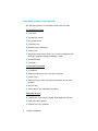
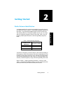
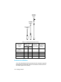
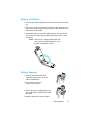
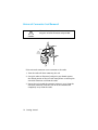
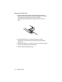
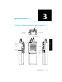
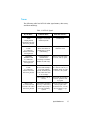
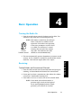
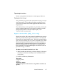
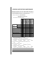
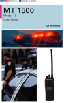
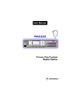
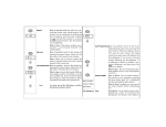
MTX•LS PORTABLE RADIOS MTX LS Operating Instructions 68P81083C35-X Contents ➠ Warnings, Cautions, and Notes . . . . . . . . . . . . . . . . . . . . . . . 3 Computer Software Copyrights . . . . . . . . . . . . . . . . . . . . . . 4 1 - Product Introduction . . . . . . . . . . . . . . . . . . . . . . . . . . . . 5 Standard Features and Benefits . . . . . . . . . . . . . . . . . . . . . . . . . . 6 Radio Feature Programming . . . . . . . . . . . . . . . . . . . . . . . . . . . . . 7 Advantages Of Trunking . . . . . . . . . . . . . . . . . . . . . . . . . . . . . . . 8 2 - Getting Started . . . . . . . . . . . . . . . . . . . . . . . . . . . . . . . . . 9 Radio/Antenna Identification . . . . . . . . . . . . . . . . . . . . . . . . . . . 9 Antenna Installation . . . . . . . . . . . . . . . . . . . . . . . . . . . . . . . . . 10 Battery Installation . . . . . . . . . . . . . . . . . . . . . . . . . . . . . . . . . . . 11 Battery Removal . . . . . . . . . . . . . . . . . . . . . . . . . . . . . . . . . . . . . 11 Universal Connector Seal Removal . . . . . . . . . . . . . . . . . . . . . . 12 Belt Clip Installation and Removal (on Nickel-Cadmium Batteries Only). . . . . . . . . . . . . . . . . . . . . . . . . . . . . . . . . . . . . . . . . . . . . . 13 Installing the Belt Clip . . . . . . . . . . . . . . . . . . . . . . . . . . . . . . 13 Removing The Belt Clip . . . . . . . . . . . . . . . . . . . . . . . . . . . . . 14 3 - Quick Reference . . . . . . . . . . . . . . . . . . . . . . . . . . . . . . . 15 Controls, Switches, Indicators, and Connectors . . . . . . . . . . . . 15 Tones. . . . . . . . . . . . . . . . . . . . . . . . . . . . . . . . . . . . . . . . . . . . . . 17 4 - Basic Operation . . . . . . . . . . . . . . . . . . . . . . . . . . . . . . . . 19 Turning the Radio On . . . . . . . . . . . . . . . . . . . . . . . . . . . . . . . . 19 Receiving. . . . . . . . . . . . . . . . . . . . . . . . . . . . . . . . . . . . . . . . . . . 19 Trunked Modes and Conventional Channels . . . . . . . . . . . . 19 Call Light (Trunking Only) . . . . . . . . . . . . . . . . . . . . . . . . . . . 20 , Motorola, MTX•LS, and Call Alert are trademarks of Motorola, Inc. LTR is a registered trademark of the E. F. Johnson Company. 1995 by Motorola, Inc. Radio Products Group 8000 West Sunrise Blvd. Ft. Lauderdale, FL 33322 Printed in U.S.A All Rights Reserved. Contents 1 Monitoring a Conventional Channel . . . . . . . . . . . . . . . . . . . . 20 Transmitting on a Trunked System . . . . . . . . . . . . . . . . . . . . . . 20 Transmitting on a Conventional Channel . . . . . . . . . . . . . . . . 21 Smart PTT . . . . . . . . . . . . . . . . . . . . . . . . . . . . . . . . . . . . . . . . . . 21 5 - Telephone Interconnect . . . . . . . . . . . . . . . . . . . . . . . . . 23 To Receive A Telephone Call . . . . . . . . . . . . . . . . . . . . . . . . . . . 23 6 - Scan . . . . . . . . . . . . . . . . . . . . . . . . . . . . . . . . . . . . . . . . . 25 Types of Scan . . . . . . . . . . . . . . . . . . . . . . . . . . . . . . . . . . . . . . . 25 Auto Group Scan . . . . . . . . . . . . . . . . . . . . . . . . . . . . . . . . . . . 25 All Group Scan . . . . . . . . . . . . . . . . . . . . . . . . . . . . . . . . . . . . 26 Mode Slaved Scan . . . . . . . . . . . . . . . . . . . . . . . . . . . . . . . . . . 26 Deleting Nuisance Modes . . . . . . . . . . . . . . . . . . . . . . . . . . . . 26 7 - Battery Information. . . . . . . . . . . . . . . . . . . . . . . . . . . . 27 Recharging Nickel-Cadmium Batteries. . . . . . . . . . . . . . . . . . . . 27 Charging Temperature . . . . . . . . . . . . . . . . . . . . . . . . . . . . . . . . 27 Short Circuit . . . . . . . . . . . . . . . . . . . . . . . . . . . . . . . . . . . . . . . . 28 Memory Effect (Reduced Charge Capacity) . . . . . . . . . . . . . . . . 28 Battery Disposal . . . . . . . . . . . . . . . . . . . . . . . . . . . . . . . . . . . . . 28 Nickel-Cadmium Battery Recycling Facility. . . . . . . . . . . . . . . . 30 8 - Optional Accessories . . . . . . . . . . . . . . . . . . . . . . . . . . . . 31 9 - Safety Information . . . . . . . . . . . . . . . . . . . . . . . . . . . . . 35 Safety Standards . . . . . . . . . . . . . . . . . . . . . . . . . . . . . . . . . . . . . 35 Restrictions . . . . . . . . . . . . . . . . . . . . . . . . . . . . . . . . . . . . . . . . . 37 Airbag Warning Statement . . . . . . . . . . . . . . . . . . . . . . . . . . . . . 38 10 - General Information . . . . . . . . . . . . . . . . . . . . . . . . . . . 39 Radio Care. . . . . . . . . . . . . . . . . . . . . . . . . . . . . . . . . . . . . . . . . . 39 Cleaning . . . . . . . . . . . . . . . . . . . . . . . . . . . . . . . . . . . . . . . . . 39 Handling . . . . . . . . . . . . . . . . . . . . . . . . . . . . . . . . . . . . . . . . . 39 Service . . . . . . . . . . . . . . . . . . . . . . . . . . . . . . . . . . . . . . . . . . . . . 40 Radio Checks. . . . . . . . . . . . . . . . . . . . . . . . . . . . . . . . . . . . . . 40 Operating Instructions . . . . . . . . . . . . . . . . . . . . . . . . . . . . . . 41 Problem(s) Not Solved . . . . . . . . . . . . . . . . . . . . . . . . . . . . . . 41 Express Service Plus (ESP), U.S.A. only. . . . . . . . . . . . . . . . . . . . 41 Parts Information . . . . . . . . . . . . . . . . . . . . . . . . . . . . . . . . . . . . 42 11 - Glossary . . . . . . . . . . . . . . . . . . . . . . . . . . . . . . . . . . . . . . 43 2 Contents Warnings, Cautions, and Notes Throughout this publication, you will notice the use of WARNINGS, CAUTIONS, and Notes. These notations are used to emphasize that safety hazards exist, and care must be taken or observed. ! WARNING ! Caution An operational procedure, practice, or condition, etc., which may result in injury or death if not carefully observed. An operational procedure, practice, or condition, etc., which may result in damage to the equipment if not carefully observed. Note: An operational procedure, practice, or condition, etc., which is important to emphasize. Warnings, Cautions, and Notes 3 Computer Software Copyrights The Motorola products described in this instruction manual include copyrighted Motorola computer programs stored in semiconductor memories or other mediums. Laws in the United States and other countries preserve for Motorola certain exclusive rights for copyrighted computer programs, including the exclusive right to copy or reproduce in any form a copyrighted computer program. Accordingly, any copyrighted Motorola computer programs contained in the Motorola products described in this instruction manual may not be copied or reproduced in any manner without the express written permission of Motorola. Furthermore, the purchase of Motorola products shall not be deemed to grant either directly or by implication, estoppel or otherwise, any license under the copyrights, patents, or patent applications of Motorola, except for the normal nonexclusive, royalty fee license to use that arises by operation of law in the sale of a product. 4 Computer Software Copyrights 1 Product Introduction The MTX•LS radio gives you the flexibility to operate on both conventional repeater systems and the popular, LTR trunking system. The radio supports up to 14 trunking systems, which lets you maintain communications while roaming from area to area. The radio also supports up to 10 conventional channels, which gives you the freedom to switch to a conventional repeater or to communicate directly with other two-way radios. O O DISK B55= REVISION ISS. DISK 0 DWG. NO. CORRECTED AS PROGRAM O.K. AS IS CORRECTED AS MARKED LETTERING SIZE: REQUIRES: TECHNICAL PUBLICATIONS DATE DATE 12/18/91 MARKED 5/16/95 DATE 12/18/91 Illustrator JWB CHECKER S.H. DATE Illustrator CHECKER EDITOR MAEPF-25075 PROGRAM ENGINEER DATE DATE ENGINEER 12/11/91 DATE 5/16/95 EDITOR EH J.W.B. MTX·LS Radio ILLUSTRATOR HT1000 Antenna nSide View MAEPF-22108 Inspect the shipping carton for any signs of damage. Remove and check the contents to be sure that all ordered items have been shipped. If items have been damaged during transit, report the damage to the shipping company immediately. S.H. DATE 0 ILLUSTRATOR DESCRIPTION ISS. 12/11/91 G.M. Radio Packing Box Contents: LETTERING SIZE: REQUIRES: CHECK ONE ( ) O.K. AS MARKED ( REVISION RLSE. ) RLSE. JWB EH 5/16/95 5/16/95 DESCRIPTION Jedi ILLUSTRATOR EH ♦ Radio EDITOR JWB DATE 12/13/9 DATE 12/18/9 LET RE ♦ Antenna ♦ Battery MTX LS ♦ Belt Clip ♦ Operating Instructions Manual ♦ Universal Connector Seal MAEPF-22109-A Product Introduction 5 Product Intro Welcome to the MTX•LS Trunked Portable Radio Family. Your choice of the Motorola MTX•LS means you have selected the highest of standards in design, quality, and performance. Standard Features and Benefits The following features are standard with the MTX•LS radio. LTR trunked operation ♦ 14 systems ♦ 3 groups per system ♦ Fast system access ♦ Automatic retry ♦ Flexible group structuring ♦ Priority Scan ♦ Telephone interconnect allows you to receive telephone calls through a properly-equipped trunking system ♦ Transmit Inhibit ♦ Call Light Conventional operation ♦ 10 channels ♦ Talkaround operation lets you bypass repeaters ♦ Priority Scan ♦ Smart PTT keeps radio users from transmitting on an active channel ♦ Receive Only ♦ Private-Line (PL) Subaudible Signalling Ergonomic design ♦ Comfortable, light weight, rugged, hand-held portable unit ♦ Easily accessible controls ♦ Remote accessory capability 6 Product Introduction ♦ Dual-height, contoured knobs ♦ Nuisance Delete of scan list members ♦ Single, top-mounted toggle switch Ease of operation ♦ Scan function allows the radio to automatically scan across any combination of 16 modes ♦ Time-Out Timer automatically shuts off transmitter after a programmable amount of transmission time Rugged, dependable design ♦ Designed to MIL-STD 810 C, D and E for shock and vibration, the toughest environmental test for a portable radio ♦ 3-Watt power output ♦ ±.00025% frequency stability ♦ Power-up check validates correct operation each time the radio is turned on Radio Feature Programming The following features of your radio can be programmed by your dealer: ♦ Conventional and trunked frequencies ♦ Trunked modes and groups ♦ Squelch ♦ Tone Private-Line (TPL) codes ♦ Digital Private-Line (DPL) codes ♦ Transmit Time-Out Timer ♦ Scan list ♦ Smart PTT Product Introduction 7 ♦ Radio Self Check Feedback ♦ Permanent Monitor ♦ Call Light ♦ Transmit Inhibit ♦ Talk Permit tone Advantages Of Trunking Trunking allows many users to share a fixed number of communication channels without interfering with one another. Telephone companies for years have used trunking to make the most efficient use of their equipment, and similar trunking methods have been adapted to two-way radio communication. A trunked radio system allows a large number of users to share a relatively small number of frequencies. When an operator establishes communication with someone else in the system, the system automatically assigns a communication path - a repeater and its frequency. Once the conversation has ended, the repeater is freed for other users. Trunking pools all the repeater air time, and this maximizes the amount of air time available to any one mobile unit and minimizes channel congestion. Some of the key benefits of trunked two-way radio systems are: ♦ No channel monitoring required prior to transmission ♦ Fast system access ♦ Automatic channel selection ♦ Privacy among members of the same group 8 Product Introduction 2 Getting Started Radio/Antenna Identification Table 1 Radio Operating Frequency Fourth-Position Character Frequency Band U 806-870MHz W 896-941MHz Antennas are frequency sensitive and are color coded according to the frequency range of the antenna. The color code indicator is the insulator in the center of the base of the antenna. The illustrations and Antenna Identification Chart (page 10) will help identify the antenna, antenna frequency range, and corresponding color code. Refer to Table 1, “Radio Operating Frequency,” on page 9 and Table 2, “Antenna Identification Chart,” on page 10 to ensure that the match between your radio and antenna is correct. Getting Started 9 Getting Started An information label is attached to the back of your radio (chassis), just under the battery contacts. A radio model number is shown on this label. A typical model number might be H01UCC6DU3AN. The fourth position of the model number (in this case “U”) identifies the operating frequency band of the radio. Table 1 lists all fourth-position alpha characters and corresponding frequency band. 800 MHz 900 MHz Dipole 800 MHz 900 MHz Whip 800/900 MHz Stubby Table 2 Antenna Identification Chart Antenna Type Approximate Length Insulator Color Code Frequency Range In. MM. 800/900 MHz Stubby, Quarterwave 3.3 83 WHITE 806-941MHz 800MHz Dipole 8 200 RED 806-870MHz 900MHz Dipole 8 200 BLUE 896-941MHz 800MHz Whip 7 175 RED 806-870MHz 900MHz Whip 6.6 165 BLUE 896-941MHz Antenna Installation Screw the threaded end of the antenna into the antenna receptacle located on top of the radio. Rotate the antenna clockwise until it fits firmly against the bushing. 10 Getting Started Battery Installation 1. Turn off the radio and hold it with the back of the radio facing up. 2. Place the two tabs of the battery (located at the inside base of the battery) into the metal cutouts of the radio (located at the inside base of the radio). 3. Rotate the battery toward the radio and press the top of the battery into the radio until both battery release levers “click” into place. NOTE: The battery is shipped uncharged. Batteries must be charged before use. (See Battery Information section.) Battery Removal 1. Turn off the radio and hold it such that the battery side of the radio is tilted down. 2. Press down on the two battery release levers. MAEPF-22057-B 3. With release levers pulled down, the top of the battery will fall away from the radio. 4. Remove the battery from the radio. Getting Started 11 Universal Connector Seal Removal When not in use, keep the side connector covered using the universal connector seal provided. ! Caution apagar Sello conector universal MAEPF-22770-O (E) If the universal connector seal is attached to the radio: 1. Turn the radio off when removing the seal. 2. Grasp the radio as illustrated, and push your thumb against the tabbed portion of the seal with enough force to unsnap the universal connector seal from the radio. 3. Rotate the seal around the antenna to move it away from the universal connector; slide the seal off of the antenna and completely away from the radio. 12 Getting Started Belt Clip Installation and Removal (on NickelCadmium Batteries Only) ! Caution Installation and removal of the belt clip assembly should be done with the battery removed from the radio or damage could be done to the radio housing. Installing the Belt Clip A Revised Belt Clip EH JWB 5/27/93 5/27/93 MAEPF-22060-A MAEPF-22061-A 1. Insert a pencil or equivalent size instrument between the inside of the belt clip and the metal clip assembly to hold the metal clip partially sprung (metal clip should be approximately parallel with the plastic portion of the belt clip). 2. Align the metal tabs of the belt clip with the plastic slots of the battery housing. 3. Slide the belt clip onto the battery, pushing firmly until you hear a click. 4. Remove the pencil from the clip. Getting Started 13 Removing The Belt Clip 1. Insert a pencil or equivalent size instrument between the inside of the belt clip and the metal clip assembly to hold the metal clip partially sprung (metal clip should be approximately parallel with the plastic portion of the belt clip). EH EDITOR JWB 12/13/91 GM DATE CHECKER 12/18/91 SH LETTERING SIZE: REQUIRES: B93 12/18/91 Illustrator DATE ISS. ( ) O.K. AS MARKED ( ) O.K. AS IS CORRECTED AS 12/13/91 MARKED RLSE. EH JWB 12/18/9112/18/91 O A RLSE. REVISION Revise Belt Clip EH JWB 5/27/93 5/27/93 MAEPF-22062-A 2. Push the flat blade of a #2 slotted screwdriver (or like instrument) between the battery housing and the belt clip release tab. 3. While performing step 2, slide the belt clip out and away from the battery, and remove the screwdriver. 4. Remove the pencil from the clip. 14 Getting Started 3 Quick Reference DAT DAT Controls, Switches, Indicators, and Connectors LETTERING SIZE: REQUIRES: JWB 7 5 5/16/95 CHECKER DATE DATE 5/16/95 3 EH 1 EDITOR 15 ILLUSTRATOR 11 9 13 ENGINEER 4 indicator LED 3 three position (ABC) toggle switch A B C 5 orange top button 2 rotary mode selector knob 1 on-off/volume control Quick Reference side button 1 side button 2 11 universal connector side button 3 push-to-talk (PTT) switch MTX LS 10 microphone 12 noisecancelling port Quick Reference 15 1 ON/OFF/ VOLUME CONTROL Turns the radio on or off and adjusts the volume level. 2 ROTARY MODE SELECTOR KNOB (16-Position) Allows you to select conventional and trunking modes. 3 THREE-POSITION (A B C) TOGGLE SWITCH Allows you to select the radio LTR operating group or conventional channel. 4 LED INDICATOR Indicates the radio’s operating status; green/red/yellow light-emitting diode (LED). (See “Indicator LED Indications” paragraph. 5 ORANGE TOP BUTTON For future use. 6 SIDE BUTTON 1 Programmed at shipment for scan on/off function. 7 SIDE BUTTON 2 Programmed at shipment for “deleting nuisance modes.” 8 SIDE BUTTON 3 Programmed at shipment for monitor operation. 9 PUSH-TO-TALK (PTT) SWITCH Puts the radio in the transmit mode. 10 MICROPHONE PORT Accepts voice input to the radio’s microphone. 11 UNIVERSAL CONNECTOR Provides access for programming, testing, and accessory connections. 12 NOISE-CANCELLING PORT Reduces background noise during transmit. 16 Quick Reference Tones The following table lists MTX•LS radio signal names, their tones, and their meanings. Table 3 MTX•LS Signals If you hear... It means that... Take this action... TALK PERMIT TONE A high-pitched dit-dit-dit tone after the PTT is pressed You made a successful attempt to access the trunked system. Proceed with conversation. TALK PROHIBIT TONE A continuous baaah tone when PTT is pressed The conventional Smart PTT function prohibited you from transmitting. Try again when channel is clear. TRANSMIT INHIBIT TONE A continuous baaah tone when PTT is pressed You attempted to transmit after receiving a Transmit Inhibit ID (LTR only). Release PTT, wait three seconds, and try again. OUT OF RANGE TONE A continuous baaah tone when the PTT is pressed You made an unsuccessful attempt to access the trunked system. Normally this occurs when the radio is out of range. Try again when you are in a better location, for example, when on a hill or closer to the system. The system is out of service. Wait until the system is back in operation and try again. All available channels are busy, or the radio is continuously trying to access the trunking system. Release the PTT switch and try again a few moments later, or hold the PTT until you get access. BUSY TONE A continuous bah bah bah tone when the PTT is pressed Quick Reference 17 Table 3 MTX•LS Signals If you hear... It means that... Take this action... VALID KEY TONE A high-pitched chirp when a button is pressed The button press was accepted. Proceed with desired function. INVALID KEY TONE A bonk tone when a button is pressed You pressed an illegal button for the current operation. Select another function. TIME-OUT TIMER WARNING TONE A bonk tone while transmitting The present transmission will end in four seconds. Finish your transmission before your transmitter is disabled. TIME-OUT TIMER TONE A continuous baaah tone when the PTT is pressed The transmission has ended. Release PTT. LOW-BATTERY TONE A cricket chirp tone on PTT release or periodically in stand-by The battery is getting low on charge. Charge the battery or replace the battery with a charged battery. PRIORITY MODE RECEIVE TONE A high-pitched chirp A priority mode was received during scan. Listen to the priority call. 18 Quick Reference 4 Basic Operation Turning the Radio On 1. Turn the on/off/volume control clockwise until it clicks. You will hear a chirp tone after a successful power-up. NOTE: Each time it is turned on, the radio performs a self check to validate correct operation. If the radio is not operating at the exact parameters set in the factory or field, you will hear a 5-second warning tone instead of the normal On/Off chirp tone. This indicates the radio Volume Control should be serviced immediately. MAEPF-22063-A 2. The unit automatically operates dependant on current switch settings. Set the volume by turning the on/off/volume control clockwise. One half turn equals about 50% output. Trunked Modes and Conventional Channels 1. Turn the radio on and select the desired mode and group for trunking, or desired mode and channel for conventional. 2. Listen until you hear a transmission, then adjust the volume control for a comfortable listening level. 3. Your radio is now set to receive calls on the selected mode. NOTE: If the mode selector knob and the 3position toggle switch are both placed on an unprogrammed position (blank position), you will hear an “invalid Basic Operation 19 Basic Operation Receiving mode” tone until the mode selector knob and 3-position toggle switch select a programmed (valid) position. NOTE: If the channel is busy during conventional operation, the radio’s red LED will blink in receive operation. NOTE: The red LED will blink if a low-battery condition occurs during transmit operation. Call Light (Trunking Only) If this feature is enabled on a group or a universal ID that is received, then the green LED will blink. To turn off the call light, change the group or mode, press the PTT, or press any valid button. Monitoring a Conventional Channel 1. To unsquelch the radio while on a conventional channel, press side button 3. This unmutes the speaker (if open squelch monitor is programmed using RSS). You may then adjust the volume with the on/off/volume control. 2. To place the radio in the permanent monitor mode, press and hold side button 3 for approximately 2.5 seconds (time programmable using RSS). The radio emits a brief high-pitched tone as it enters the permanent monitor mode. To return the radio to its original squelch state, one of the following can be done: press side button 3 again, press the PTT (Push To Talk) switch, change modes or channels, or turn the radio off and on. Transmitting on a Trunked System 1. Press the PTT switch. 2. If the dit-dit-dit talk permit tones (programmed using RSS) are heard, continue to push the PTT switch and speak into the microphone in a normal voice. The red LED indicator will stay 20 Basic Operation on continuously to indicate that you are “on the air.” 3. If you hear other tone(s) when you push the PTT switch, the radio is alerting you that certain system conditions exist. Refer to Table 3, “MTX•LS Signals,” on page 17. 4. If your radio has the Time-Out-Timer function activated, transmission will terminate if you hold down the PTT switch for more than a preprogrammed time period (programmed using RSS). When time-out occurs, a bonk alert tone sounds 4 seconds before the transmission is terminated. If the PTT switch is not released within 4 seconds, the radio stops transmitting and a continuous alert tone is generated until the PTT switch is released. To resume transmitting, release the PTT switch and push again. Transmitting on a Conventional Channel 1. The red LED indicator will flash if there is another unit active on the channel. Do not transmit if anyone else is using the channel. 2. When you press the PTT, the red LED indicator will stay on continuously to indicate that you are “on the air.” If you hear tone(s) when you push the PTT switch, the radio is alerting you that certain system conditions exist. Refer to Table 3, “MTX•LS Signals,” on page 17. 3. If your radio has the Time-Out-Timer function activated, transmission will terminate if you hold down the PTT button for more than a preprogrammed time period (programmed using RSS). When time-out occurs, a bonk alert tone sounds 4 seconds before the transmission is cut. If the PTT switch is not released within 4 seconds, the radio stops transmitting and a continuous alert tone is generated until the PTT switch is released. To resume transmitting, release the PTT switch and push again. Smart PTT Smart PTT is a per-channel feature which gives the system manager better control of radio operations. When smart PTT is activated in your radio (using RSS), the user will not be able to transmit on Basic Operation 21 an active channel. Three radio-wide variations of smart PTT are available: 1. Transmit Inhibit on Busy Channel: With this feature enabled, you will be inhibited from transmitting if any activity is detected on the channel. 2. Transmit Inhibit on Busy Channel with Wrong Squelch Code: With this feature enabled, you will be inhibited from transmitting on an active channel with a squelch code other than your own. If the squelch code is the same as yours, the transmission will not be inhibited. 3. Quick-Key Override: This feature can work in conjunction with variation one or two. With this feature enabled, you will be able to override the transmit inhibit state by quick-keying (two PTT activations within one second of each other) the radio. Smart PTT radio operation is exactly the same as standard radio operation, except that if you try to transmit (press PTT) on a Smart PTT channel, a continuous alert tone is generated until the PTT is released; the transmission is inhibited. 22 Basic Operation Telephone Interconnect 5 Your MTX•LS radio is equipped with Telephone Interconnect, which allows you to receive calls from landline telephones through the trunking system central computer. Calls from the landline user can be private or can include a whole group. Keep in mind that a radio operator can either talk or listen at one time, whereas the landline user has duplex (talk and listen) operation. This means a radio operator who is speaking will not hear an interruption from the landline user. Therefore, the landline user should be warned to listen for a beep (system dependent) before speaking. To Receive A Telephone Call 1. To make a call to the radio, the landline party will dial an interconnect terminal phone number. If the system is busy, the landline party hears a normal busy signal, and must hang up and try again. If the phone line is open, the caller will hear a tone (system dependent). The caller should then enter the access code assigned to the desired radio unit. Both the landline and the radio user will hear a ringing tone. 2. To answer, press the PTT and begin talking. 3. Keep these points in mind during your conversation: ◊ If the landline user speaks while you are transmitting, you will not hear them. Proceed with the conversation in a normal two-way radio manner by pushing the PTT switch Telephone Interconnect 23 Telephone ◊ The landline user should be informed that you are using a radio and that replies should be made only after you have finished transmitting. The landline user will hear a soft beep (system dependent) after you release the PTT switch. Explain that only one person can talk at a time. to transmit and releasing the PTT switch to listen. NOTE: During phone, several users may share the same ID. Therefore, courtesy must be used when answering a call or during a phone conversation since multiple users can respond simultaneously. 4. To disconnect the call and return to dispatch operation, the call will be terminated by the landline user or by the system time-out timer. 24 Telephone Interconnect 6 Scan Scan is a feature that allows your MTX•LS portable radio to search for, lock onto, and monitor activity on conventional channels or trunked groups. For mode slaved scan, as many as sixteen modes can be RSS programmed, which may include up to 14 trunked modes or up to 10 conventional channels. Three types of scan are available, Auto Group Scan, All Group Scan, and Mode Slaved Scan. Auto Group Scan and All Group Scan are LTR trunking features. Mode Slaved Scan is a trunking and conventional scan feature. All of the scan features in this radio are programmed using RSS, and are not front panel programmable. Types of Scan Auto Group Scan In Auto Group Scan, only certain groups within the selected mode (programmed via RSS) will be scanned. If a group is programmed for this feature, scanning begins when that group is selected. NOTE: The 16-position switch must be set to a trunking mode, and the three-position toggle switch placed in a position with scan enabled (either A, B, and/or C) for scanning to begin. 11 3 3-Position MAEPF-22068-A Toggle Switch 1 5 15 7 9 13 A B C MAEPF-22065-O 16-Position Switch Scan Scan 25 All Group Scan In All Group Scan, all groups within the mode (selected via the 16position switch) will be scanned. If the mode selected is programmed with this feature, scanning begins with a long press (approximately 1.5 seconds - RSS programmable) of side button 1. During All Group Scan, the LED double-blinks yellow. Exit scan by changing modes, by a momentary press of side button 1, or by turning the radio off. Mode Slaved Scan With this feature, a scan list is programmed directly to a mode (selected by the 16-position switch). Scanning begins with a short (momentary) press and release of side button 1. During Mode Slaved Scan, the LED blinks yellow. Exit scan by changing modes, by a momentary press of side button 1, or by turning the radio off. NOTE: An MTX•LS radio, Mode Slaved Scan, can be RSS programmed per mode for priority and non-priority scan. Priority modes in the list are scanned more often than non-priority modes in the list. Deleting Nuisance Modes When the radio scans to a mode that you do not wish to hear (nuisance mode), you can temporarily delete the mode from the scan list. 1. When the radio is locked onto the mode to be deleted, press the nuisance mode delete button, side button 2. A valid key tone is heard, indicating that the mode has been deleted. Neither the priority mode nor the selected mode may be deleted from the scan list. 2. The radio continues scanning the remaining modes in the list. To resume scanning the deleted mode, you must exit and reenter scan operation. 26 Scan 7 Battery Information Recharging Nickel-Cadmium Batteries Recharge the battery before use to ensure optimum capacity and performance. The battery was designed specifically to be used with a Motorola charger. Charging in non-Motorola equipment may lead to battery damage and void the battery warranty. NOTE: Note: When charging a battery that is attached to the radio, turn the radio off to ensure a full charge. ! WARNING Do not attempt to change or charge the battery in a hazardous atmosphere. See Safety Standards section of this manual. Charging Temperature The battery should be at room temperature (about 77°) whenever possible. Charging a cold battery (below 50° F) may result in leakage of electrolyte and ultimately, in failure of the battery. Charging a hot battery (above 95° F) results in reduced discharge capacity, affecting the performance of the radio. MTX•LS rapid-rate battery chargers contain a temperature-sensing circuit to ensure that the battery is charged within these temperature limits. Battery Information 27 Battery Info The MTX•LS radio receives its power from a rechargeable nickelcadmium (NiCd) battery as listed in the accessories section. These batteries are a safe, dependable power source for your radio. Proper care of the battery will ensure its effectiveness and allow for peak radio performance. Short Circuit Care should be taken to avoid external short-circuiting of the battery. A sustained high-rate discharge (for example, a paper clip placed accidently across the battery contacts) may permanently damage WARNING the battery, void the battery warranty, and create a burn or fire hazard. ! Memory Effect (Reduced Charge Capacity) Memory effect is a phenomenon which causes a temporary loss in battery capacity or voltage due to repetitive shallow discharging or long-term overcharging. This memory effect has been virtually eliminated from Motorola batteries through the use of new cell technology. Battery Disposal For disposal, nickel-cadmium sealed rechargeable batteries should be delivered to an authorized metals-reclamation dealer. ! Do not dispose of any batteries in a fire as they may explode! WARNING This product is powered by a nickel-cadmium rechargeable battery. At the end of its useful life, the battery can be recycled. However, recycling facilities may not be available in all areas. Under various state or local laws, the battery must be recycled or disposed of properly, and cannot be disposed of in landfills or incinerators. In addition, U.S. Environmental Protection Agency (EPA) regulations classify used nickel-cadmium batteries as hazardous waste, unless certain exemptions apply. 28 Battery Information Motorola fully endorses and encourages the recycling of nickelcadmium batteries. If you are located in the United States, you can ship, postpaid, your used Motorola nickel-cadmium batteries to INMETCO, an EPA-approved recycling facility at the address given on the next page. We recommend used batteries be sent to the nickel-cadmium recycling facility. Should you have any questions, contact the facility first. Consideration should be given to the methods of collecting, labeling, and shipping used nickel-cadmium batteries. Your federal, state, or local EPA should be consulted for specific requirements and for recycling options in your area. Motorola, as a responsible corporate citizen, has always been concerned with the protection of the environment. For further information, you may call the Motorola America’s Parts Division, Customer Service Department, toll-free at 1-800-422-4210. Battery Information 29 Nickel-Cadmium Battery Recycling Facility INMETCO, Bin # M1 P.O. Box 7202 245 Portersville Road Ellwood City, PA 16117 Phone: (412) 758-2800 Fax: (412) 758-9311 For additional information, write to: Motorola Energy Products Division Customer Care Department 1700 Belle Meade Court Lawrenceville, GA 30243-5854 30 Battery Information 8 Optional Accessories Motorola offers several accessories to increase communications efficiency. Many of the accessories are listed. Contact your Motorola dealer for other accessories that apply to your MTX•LS radio and your particular needs. Antennas *Whip (800MHz) *Whip (900MHz *Dipole (800MHz) *Dipole (900MHz) *Quarter Wave, Stubby (800MHz, 900MHz) Accessories NAF5037 NAF5038 NAF5039 NAF5040 NAF5042 Batteries NTN7143 High-Capacity Nickel-Cadmium (Non-incentive, groups A, B, C, D) NTN7144 Ultra-High-Capacity Nickel-Cadmium (Non-incen tive, groups A, B, C, D) NTN7146 *High-Capacity Nickel-Cadmium FMRC Intrinsically Safe (groups D, F, G) NTN7147 *Ultra-High-Capacity Nickel-Cadmium FMRC Intrinsically Safe (groups D, F, G) NTN7341 *High-Capacity Nickel-Cadmium FMRC Intrinsically Safe (groups C, D, E, F, G) NTN7372 *Ultra-High-Capacity Nickel-Cadmium FMRC Intrinsically Safe (groups C, D, E, F, G) Battery Chargers Single-Unit Slow-Charge, 50/60Hz Desk-Top: NTN1174 117Vac, with 117Vac Wall-Mount Transformer NTN1175 220Vac with International Wall-Mount Transformer NTN1176 240Vac with International Wall-Mount Transformer Optional Accessories 31 Single-Unit Rapid-Charge, 50/60Hz Desk-Top: NTN1171 117Vac, with 117Vac Cord and Plug NTN1172 220Vac with International 220Vac Cord and Plug NTN1173 240Vac with International 240Vac Cord and Plug Single-Unit Dual-Rate Battery Chargers, 50/60Hz Desk-Top: NTN1168 117Vac with 117Vac Cord and Plug NTN1169 220Vac with International 220Vac Cord and Plug NTN1170 240Vac with International 240Vac Cord and plug Multi-Unit Battery Chargers, Six-Pocket Dual-Rate 50/60Hz: NTN1177 90-240Vac, with 117Vac Cord and Plug NTN1178 90-240Vac with International 220Vac Cord and Plug NTN1179 90-240Vac with International 240Vac Cord Plug Remote Speaker/Microphones NMN6191 *Noise-Canceling Microphone; Includes Coiled Cord Assembly, 3.5mm Earjack, and Swivel Clip NMN6193 *Standard Microphone; Includes Coiled Cord Assembly,3.5mm Earjack, and Swivel Clip Carry Accessories NLN6042 NLN6349 NLN8410 NTN7238 NTN7239 NTN8035 NTN8036 NTN8037 NTN8038 NTN7247 NTN7317 NTN7318 32 3" Black Belt Shoulder Carry Strap Velcro Patch Pin Attachment Leather Carry Case with Belt Loop and T-Strap for High-Capacity Leather Carry Case with Belt Loop and T-Strap for Ultra-High-Capacity Leather Carry Case with High Activity Swivel 2.5" Belt Loop and T-Strap for High-Capacity Leather Carry Case with High Activity Swivel 2.5" Belt Loop and T-Strap for Ultra-High-Capacity Leather Carry Case with High Activity Swivel 3.0" Belt Loop and T-Strap for High-Capacity Leather Carry Case with High Activity Swivel 3.0" Belt Loop and T-Strap for Ultra-High-Capacity Fabric Carry Case with Belt Loop for High- and Ultra-High-Capacity Belt Clip (Fits 2.5" Belt) Belt Clip (Fits 3.5" Belt) Optional Accessories * These accessories are approved as being intrinsically safe by Factory Mutual Research Corporation (FMRC). Refer to the radio label for intrinsic safety ratings and required batteries. Only the accessories and antennas noted by an asterisk (*) may be used on approved radios. ! Substitution of components may impair the intrinsic safety of the radio. WARNING Optional Accessories 33 NOTES 34 Optional Accessories 9 Safety Information Safety Standards The Federal Communications Commission (FCC), has adopted a safety standard for human exposure to radio frequency electromagnetic energy emitted by FCC regulated equipment. Motorola subscribes to the same safety standard for the use of its products. Proper operation of this radio will result in user exposure substantially below FCC recommended limits: ♦ Do not hold the radio with the antenna very ♦ Do not hold the transmit switch (PTT) on when not actually desiring to transmit. ♦ Do not allow children to play with any radio equipment containing a transmitter. ♦ Do not operate this equipment near electrical blasting caps or in an explosive atmosphere. Under certain conditions, radios can interfere with blasting operations. When you are in the vicinity of construction work, look for, and observe signs cautioning against radio transmission. If radio transmission is prohibited, you must not transmit until out of the area. Furthermore, you must turn off your radio to prevent any accidental transmission. ♦ Do not replace or charge batteries in a hazardous atmosphere. Contact sparking may occur while installing or removing batteries and cause an explosion. ♦ Turn radio off when removing or installing a battery. Safety Information 35 Safety Info close to, or touching, exposed parts of the body, especially the face, ears, or eyes, while transmitting. Hold the radio in a vertical position with the microphone two to three inches away from the lips. Anyone intending to use a radio in a hazardous area is advised to become familiar with the subject of intrinsic safety and with Section 70 of the National Fire Code, which is commonly referred to as Article 500 of the National Electric Code. Use of anything but factory supplied components may affect the approval and safety of the radio. Likewise, it is advised that servicing should be performed only by qualified personnel who adhere to the following Factory Mutual Research Corporation (FMRC) required warning: ! WARNING Modification of FMRC-Approved intrinsically safe radios will negate Factory Mutual Research Corporation Approval. Certain MTX•LS radios and batteries have been declared intrinsically safe by FMRC of Norwood, Massachusetts, for use in hazardous atmospheres. FM Approved radios are identified by attached certification labels and by matching green dots found on the bottom of radios and batteries. The intrinsically safe rating by Factory Mutual Research Corporation states that electrical equipment is incapable of releasing sufficient electrical or thermal energy, under normal or abnormal operating conditions, to cause ignition of a specific hazardous atmosphere. This means the MTX•LS radio has been thoroughly tested by Factory Mutual Research Corporation and carries its certification for operation in the hazardous atmospheres designated on the radio label. Radios must ship from the Motorola factory with the hazardous atmosphere capability and cannot be modified in the field. Failure to use the radio with the approved battery will negate the approval. MTX•LS radios that are approved by Factory Mutual Research Corporation can be used in those applications requiring reliable two way hand-held radios in the listed specific hazardous atmospheres. Motorola approved equipment and accessories, along with competitive equipment approvals, are listed in the yearly approval guide published by Factory Mutual Research Corporation. This guide can be ordered from the following address: 36 Safety Information Training Resource Center, Publications-Order Processing Dept. Factory Mutual Engineering and Research, 1151 Boston-Providence Turnpike P.O. Box 9102, Norwood, MA 02062 Telephone: (617) 762-4300, extension 2152 Restrictions Because this radio contains a transmitter, federal law prohibits unauthorized, non-licensed personnel from adjusting or maintaining it. If any operational difficulties should arise while using this product, report them to authorized service personnel as soon as possible. ! Do not attempt any unauthorized modification to the radio or accessories. WARNING In the U.S.A., FCC Regulations prohibit this radio from transmitting in the Public Safety band (821-825MHz), except for the Mutual Aid channels. NOTE: Operators are responsible to ensure that local regulations are met. Safety Information 37 Airbag Warning Statement ! WARNING VEHICLES EQUIPPED WITH AIR BAGS An air bag inflates with great force. DO NOT place objects, including communication equipment, in the area over the air bag or in the air bag deployment area. If the communication equipment is improperly installed and the air bag inflates, this could cause serious injury. ♦ Installation of vehicle communication equipment should be performed by a professional installer/technician qualified in the requirements for such installations. An air bag’s size, shape and deployment area can vary by vehicle make, model and front compartment configuration (e.g., bench seat vs. bucket seats). ♦ Contact the vehicle manufacturer’s corporate headquarters, if necessary, for specific air bag information for the vehicle make, model and front compartment configuration involved in your communication equipment installation. 38 Safety Information General Information 10 Radio Care Cleaning Clean external surfaces of the radio with a mild detergent and a stiff, non-metallic, short-bristled brush. A suitable detergent solution may be mixed by adding one teaspoon of mild dishwashing detergent to one gallon of water (0.5% solution). Apply the detergent solution sparingly with the brush, being careful not to allow excess detergent to remain entrapped near connectors and controls or in cracks and crevices. Do not submerse the radio in the detergent solution. Dry the radio thoroughly with a soft, lint-free cloth. Clean all battery contacts with a lint-free cloth to remove dirt, grease, or other foreign material that may prevent good electrical connections. ♦ Avoid physical abuse; do not pound, drop, or throw the radio unnecessarily. Do not carry the radio by the antenna. ♦ Avoid subjecting the radio to an excess of liquids. Never allow the radio to become submersed. ♦ Avoid subjecting the radio to corrosives, solvents, or spirits. ! Caution Clean the radio with the recommended solution only. Cleaning the radio with solvents or spirits may be harmful and permanently damage the radio housing. General Information 39 General Info Handling Do not disassemble the radio in any way. Keep the connector cover in place until ready to use the accessory connector. Replace the cover immediately after the accessory has been disconnected. Service, U.S.A. only Proper repair and maintenance procedures will assure efficient operation and long life for this product. A Motorola maintenance agreement will provide expert service to keep this and all other communication equipment in perfect operating condition. A nationwide service organization is provided by Motorola to support maintenance services. Through its maintenance and installation program, Motorola makes available the finest service to those desiring reliable, continuous communications on a contract basis. Motorola's Customer Service Division is the largest service organization specializing in mobile communications. It includes over 900 authorized or company-owned stations. In addition, our products are serviced throughout the world by a wide network of company or authorized independent distributor service organizations. For a contract service agreement, please contact your nearest Motorola service representative, authorized Motorola dealer, or Motorola sales representative. If you suspect a radio problem, check the following items before requesting service. Radio Checks ♦ Be sure the radio is turned on and both the 16-position switch and the 3-position toggle switch are in the proper positions. ♦ Replace or recharge the battery. The first time a new battery is used, it should charge a minimum of 16 hours. ♦ Antenna must be screwed on properly; the base flush against the radio top. ♦ Could your radio problem be caused by accessories connected improperly? 40 General Information Operating Instructions Review your operation instructions to ensure proper radio use. Problem(s) Not Solved After performing suggested radio checks and reviewing your operating instructions, if your radio still exhibits a problem, review your service agreement and call the applicable Motorola service representative. If you do not have a service agreement on your radio, contact your nearest authorized Motorola service shop for guidance toward a prompt and expedient evaluation and/or repair, or call 1-800-247-2346, extension 8615. Express Service Plus (ESP), U.S.A. only Express Service Plus (ESP) is an optional extended service coverage plan. ESP provides for the repair of this product, at the Motorola Factory Service Center listed in step 3, below, for a period of three years (one year warranty plus two years of extended service) from the date of shipment from the factory, or the date of delivery if purchased from an authorized Motorola two-way radio dealer. If ESP has been purchased, the serial number of this product has been registered for coverage under Express Service Plus at the depot listed in step 3, as follows. To obtain service under Extended Service Plus: 1. Check to make sure the battery or battery charger of the unit is not defective. (Batteries and chargers are excluded from this service plan). 2. Include the following information: Your name Company name Address Telephone number A brief description of the nature of the problem or failure (be specific) General Information 41 3. Pack and ship the unit (prepaid) to: Motorola Factory Service Center 1318 N. Plum Grove Road Schaumburg, IL 60173 Express Service Plus is subject to Motorola standard terms and conditions. ESP does not include repairs which will be necessary due to damage caused by accidents, physical abuse or misuse of the product(s), acts of God, and fires. Batteries, battery chargers, and external accessories are excluded from this plan. Service under ESP is available only at the service center listed herein. If you are unsure as to whether your radio is covered under Express Service Plus, call the depot at (708) 576-5760. Parts Information 7:00 A.M. - 7:00 P.M. (CST) Monday - Friday (Chicago, U.S.A.) Domestic (U.S.A.) 1-800-422-4210 1-800-826-1913 (Federal Government) TELEX: 280127 FAX: 1-708-538-8198 FAX: 1-301-925-2690 (Federal Government) Domestic (U.S.A.) after hours or weekends 1-800-325-4036 or 1-708-576-5111 International 1-708-576-9271 TELEX: 403305 MOTO PART SHBU UD FAX: 1-708-576-3023 TWX: 910-693-0869 No International weekend service is available. 42 General Information Glossary 11 Call Light RSS programmed so that the LED will blink green to indicate that a trunking group or universal ID has been received. Channel Defines conventional transmit and receive frequencies and muting conditions. DPL Digital Private-Line; digitally coded squelch, a digital version of TPL. Group A base unit of LTR trunking structure. Receive and transmit IDs, as well as other various features are defined here. LTR Logic Trunked Radio; a registered trademark of E. F. Johnson Company. Mode PTT Push-To-Talk. The switch located on the side of the radio which, when pressed, causes the radio to transmit. When the PTT is released, the radio receives. Glossary 43 Glossary A collection of LTR groups or conventional channels (can not have both types on one mode). Repeater A special, fixed two-way radio that receives and re-transmits signals in order to improve communications coverage. RSS Radio Service Software. Used by dealers to pre-program certain functions of your radio, such as scan lists and the Time-Out Timer. Squelch Muting of an audio circuit when the received signal level falls below a pre-determined value. This prevents you from having to listen to constant static on your radio. Talkaround The ability to “talk around” a repeater by communicating directly with another mobile or portable radio. Time-Out Timer A programmable function that limits the amount of time the radio can transmit (that is, the amount of time the PTT can be pressed without releasing). When this function is activated, a warning tone sounds 4 seconds before the transmitter is cut off. The TimeOut Timer can be disabled or set to a preprogrammed time value (programmed via RSS). TPL Tone Private-Line; Continuous Tone Coded Squelch System (CTCSS), industry standard. Universal ID Priority ID assigned per mode (may have none or up to 4). 44 Glossary OPERATING INSTRUCTIONS QUESTIONNAIRE We believe that reports from users provide valuable information for producing quality operating instructions. Your comments and answers to the following questions will aid us in preparing manuals that contain accurate and complete information of maximum benefit to you. In reference to Manual No. 68P81083C35-O MTX•LS Series Portable Radios Controls and Features text illustrations Operating Procedures text illustrations Not Covered in This Manual Incorrect Incomplete Complete Adequate Too Brief Too Detailed Confusing Please check all the appropriate boxes: Clear 1. Alert Tone Explanations Battery Information Options Model Information Accessories General Care Information Other (specify) 2. For illustrating procedures, do you prefer: photographs ❒ line drawings ❒ no preference ❒ 3. How would you rate the overall organization of this manual? ❒ very good ❒ good ❒ fair excellent ❒ ❒ poor ❒ poor 4a. If this manual has a "quick reference card," do you use it? ❒ yes ❒ no 4b. If yes, how useful is it to you? ❒ extremely ❒ very 5. somewhat How do you rate this manual overall? excellent ❒ very good ❒ good ❒ 6. ❒ ❒ not very ❒ fair Comments/Recommendations for improving operating instructions. From: PERMIT NO. 9040 FT. LAUDERDALE, FL Attn: Technical Publications Room 2352 8000 W. SUNRISE BOULEVARD FT. LAUDERDALE, FLORIDA 33322 Radio Products Group POSTAGE WILL BE PAID BY ADDRESSEE FIRST CLASS MAIL BUSINESS REPLY MAIL NO POSTAGE NECESSARY IF MAILED IN THE UNITED STATES ____________________________________________ ____________________________________________ MODEL # F.O. # ❑ YES ❑ NO 5. RESPONDER'S PHONE NAME ADDRESS CITY CUSTOMER NAME WORK ORDER NO. STATE 4. COMMENTS / SUGGESTIONS ZIP CODE CUST. NO. 3. HOW WAS PROBLEM FIXED? (identify location by circuit symbol & part no.) 2. IF NOT, WHAT IS NATURE OF PROBLEM? (record any reading that was off) 1. DID UNIT PERFORM PROPERLY? DATE __________________TESTED BY___________________ ____________________________________________ SERIAL # Please return this card immediately after testing or installation of your unit. HELP INITIAL PRODUCT PERFORMANCE REPORT In a continuing effort to provide a better product, we need your PUBLICATIONS AVAILABLE ❑ ❑ PLEASE DO NOT USE POST OFFICE BOX NUMBER FOR RETURN ADDRESS. ZIP CODE: ADDRESS: NAME: Service Manual................................................68P81200C40 Theory/Troubleshooting Manual......................68P81200C15 Manual(s) are available to support maintenance and servicing of your Motorola product. Print your name, address, and zip code clearly in the area provided below, and mail the card. We will send you one each of the latest up-to-date manual(s) indicated. PLACE STAMP HERE Radio Products Group Attention: Bindery 8000 W. Sunrise Boulevard Ft. Lauderdale, FL 33322 NO POSTAGE NECESSARY IF MAILED IN THE UNITED STATES BUSINESS REPLY MAIL FIRST CLASS MAIL PERMIT NO 4023 FT. LAUDERDALE, FL POSTAGE WILL BE PAID BY ADDRESSEE Radio Products Group Attn: Director of Quality Assurance 8000 W. Sunrise Boulevard Ft. Lauderdale, FL 33322