1
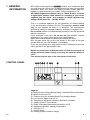
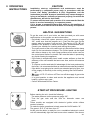
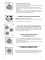
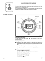
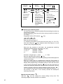
Users
Manual
403
Dear Customer,
Thank you for choosing an ARISTON boiler.
We guarantee that your boiler is a
reliable and technically sound product.
This User’s Manual provides detailed instructions and recommendations for proper installation,
use and maintenance.
Remember to keep this manual in a safe place for future reference i.e. by the gas meter.
Your local MTS Servicing Centre is at your complete disposal for all requirements.
MTS (GB) Limited
The guarantee on this appliance is valid
for 12 months from the first day of
installation.
Repairs to the electric, hydraulic or gas
circuits may be carried out only by your
local authorised MTS Servicing Centre.
Every attempt has been made to avoid errors of
any kind
in this User’s Manual, the Management
invites customers to inform
of any inaccuracies which they may find.
This will help to improve our service
IMPORTANT
Please read this manual carefully.
For additional information, please consult the “Installation and Servicing Instructions.”
Please ensure manuals provided are kept with the appliance so that they can be used by the enduser, installer or our authorised engineer.
TABLE OF CONTENTS
1) GENERAL INFORMATION
2) OPERATING INSTRUCTIONS
3) TIME CLOCK
4) USEFUL INFORMATION AND TROUBLESHOOTING
2
page
page
page
page
3
4
7
10
403
1. GENERAL
INFORMATION
MTS (GB) Limited support the
initiative. Your installer will give
you, and show you how to use, a logbook which will give you important
information about your boiler, and heating system. Please have this
logbook to hand whenever you contact a service engineer or us.
All CORGI Registered Installers carry a CORGI ID card, and have
a registration number. Both should be recorded in your boiler
Logbook. You can check your installer is CORGI registered by
calling CORGI direct on :- (01256) 372300.
This is a combined appliance for the production of central heating
(C.H.) and domestic hot water (D.H.W.). This appliance must be used
only for the purpose for which it is designed. The manufacturer
declines all liability for damage caused by improper or negligent use.
Do not allow children or inexperienced persons to use the appliance
without supervision.
If you smell gas in the room, do not turn on light switches, use the
telephone or any other object which might cause sparks.
Open doors and windows immediately to ventilate the room.
Shut the gas mains tap (on the gas meter) or the valve of the gas
cylinder and call your Gas Supplier immediately.
If you are going away for a long period of time, remember to shut the
mains gas tap or the gas cylinder valve.
Before any intervention within the boiler it is first necessary to cut
off the electrical power supply by turning the external switch to
“OFF”.
This manual may be kept in the front panel of the boiler.
CONTROL PANEL
FR004A
Legend
A)
B)
C)
D)
E)
F)
G)
H)
I)
L)
O)
403
Ignition Lockout Reset Button/Safety (Overheat)Thermostat Reset
Ignition Lockout L.E.D.
Selector Knob for Summer/Winter/Flue Analysis Modes
Low System Water Level L.E.D.
Temperature Adjustment Knob for Domestic Hot Water
Heating System Thermometer
Safety (Overheat)Thermostat Intervention L.E.D.
Adjustment Knob for Heating Temperature
On/Off L.E.D.
On/Off Switch
Heating System Pressure Gauge
3
2. OPERATING
INSTRUCTIONS
CAUTION
Installation, start-up, adjustments and maintenance must be
performed by a competent person only, in accordance with the
current Gas Safety (Installation & Use) Regulations and the
instructions provided. Improper installation may cause damage or
injury to individuals, animals and personal property, for which the
manufacturer will not be held liable.
To ensure efficient and safe operation it is recommended that the
boiler is serviced annually by a competent person.
If it is known or suspected that a fault exists on the appliance, it
must not be used until the fault has been corrected by a competent
person.
HELPFUL SUGGESTIONS
O
UT001A
I
I
L
UT008Aa
To get the most out of your boiler, we have provided you with some
useful advice on the proper use and maintenance:
- Periodically check the system pressure using the pressure guage
“O”, make sure that the pressure at 1.5 bar (the blue part on the
gauge) when the system is off and cool. The warning L.E.D. “D” will
indicate if the pressure is below the minimum recommended value.
Consult your installer for checking and refilling the system.
- The outer panels of the unit's case must only be cleaned with a damp
cloth. Do not use abrasive cleaners. The Control panel can be wiped
with either a damp or dry cloth. Spray polishes must not be used on
the control panel surface or knobs. Care must be taken in preventing
any liquid entering the appliance.
- If the water is exceptionally hard, install a water softener so that the
efficiency of the unit remains the same over time, as this will consume
less gas.
- To improve comfort and take full advantage of the heat produced by
the boiler, it is recommended that an external thermostat be installed.
- If the boiler is not going to be used for an extended period of time, turn
off the supply of electricity to the unit by pressing the On/Off switch
“L”.
- The
I green L.E.D. “I” will turn off. Then turn off the supply of gas to the
unit itself.
- It is good practice to clean and service the appliance and central
heating system every year.
- Call an Authorised Service Centre.
START-UP PROCEDURE LIGHTING
I
I
L
UT008Aa
4
Before starting the unit, check the following:
· The water pressure on the pressure gauge “O”;
· That the gas cock and the inlet for domestic water are
open.
These models are equipped with electronic ignition which utilises
contact ionisation.
To make the boiler operational, simply press the On/Off switch “L”.
The green L.E.D. “I” will then turn on.
At this point the boiler is ready for use: a centralised electronic control
unit will automatically light the main burner when needed. If the burner
403
does not light within the pre-set safety time limit, the red “B” L.E.D. will
light up. To reset the ignition system, the reset button “A” must be
pressed. Should the system fail to light a second time, check to make
sure that the gas cock is open. If the problem persists, contact one of
our Authorised Service Centres for assistance.
B
A
UT008Ab
WINTER AND SUMMER OPERATING MODES
C
UT008Ac
The boiler is fitted with a selector knob “C” which allows you to switch
between winter <
> and summer <
> and also heating only <
> operating modes and vice versa. When the knob is set to <
>, the boiler can serve the dual purpose of providing heat and/or hot
water for domestic use.
The supply of hot water for domestic use always takes precedence
over heating. When the knob is set to <
>, the boiler cuts out the
heating system and only provides hot water for domestic use (when
needed).
TURNING ON THE CENTRAL HEATING
I
Installation without a room thermostat :
- Turn on the power supply to the boiler by pressing the
On/Off switch “L”; the green L.E.D. “I” will then turn on;
I
L
UT008Aa
C
- Turn the “C” selector knob to <
domestic hot water is produced);
> or <
> (in this position no
- Regulate the temperature of the water in the boiler by turning the “H”
knob. The temperature can vary between 42°C and about 82°C;
UT008Ac
- Check the boiler temperature on the thermometer with the yellow
L.E.D.s “F”. With this type of installation, the ambient temperature
does not influence the operation of the boiler and the circulation
pump always remains in operation.
H
F
°C
UT008Ad
403
40 50 60 70 80
UT008Ae
5
Installation with a room thermostat:
- Turn the “C” selector knob to <
>;
- Turn on the power supply to the boiler by pressing the On/Off switch
”L”; the green L.E.D. will then turn on;
- Turn the thermostat knob “H” to the highest temperature setting.
- With this type of installation, the boiler is controlled by a room
thermostat
. Therefore, it runs until the ambient temperature has reached the
temperature setting on the thermostat. At that point, the main burner
will turn off and the circulation pump will stop.
H
UT008Af
C
TURNING OFF THE CENTRAL HEATING
Installation without a room thermostat:
To turn off the heating, turn the “C” selector knob to <
will still provide hot water for domestic use.
>. The boiler
UT008Ag
From +5°C
to +15°C
H
To economise on consumption while achieving the highest level of
comfort, the temperature adjustment knob is designed with three
different heating zones based on the temperature outside the home.
Rotate the knob “H” as shown below.
•
•m
min
ax
•
•m
min
Lower
than -5°C
ax
•
•m
min
ax
ADJUSTING THE HEATING TEMPERATURE
From +5°C
to -5°C
UT008Ah
mi
ax
E
n
m
•
•
PRODUCTION OF HOT WATER
FOR DOMESTIC USE
- Turn on the power to the boiler by pressing the On/Off switch “L”;
- Turn the “C” selector knob to <
> or <
> (in this position no
central heating is produced);
- Turn the “E” knob to select the temperature for the hot water
(between 40°C and about 70°C).
UT008Ai
ADJUSTING THE TEMPERATURE OF
WATER FOR DOMESTIC USE
•
•m
min
ax
E
It is recommended that the temperature for the hot water should not be
set to high temperatures and then mixed with cold water. Setting the
thermostat to medium temperatures is preferable (see figure).
UT008Al
6
403
SHUTDOWN PROCEDURE
I
I
To turn off the main burner, simply press the On/Off switch “L”; the
green L.E.D. “I” will also turn off.
As a precautionary measure, it is recommended that the gas cock
located on the bottom of the boiler be turned off as well.
L
UT008Aa
3. TIME CLOCK
Manual switch
Summer and
winter time
setting
Reset
Enter
the hours
h
Prog
.
Enter
switching
times
Weekdays
flash
m
Input
Imput
time
Enter
minutes
Day
Enter
weekday/s
Operating the time switch
The step marked with the symbol “
switching program.
UT008Am
” are necessary to carry out a
Preparing for Operation
Activate the “Res” switch (=RESET) to reset the time switch to its
default setting (activate using a pencil or similar pointed instrument). Do
this:
- every time you wish to “reset” the time switch
- to erase all switching times and the current time of day.
After approximately two seconds the following display appears:
Enter current time and weekday
- Keep the “
” key pressed down
During the summer time period press the +/- 1h key once.
Enter the hour using the “h” key
Enter the minutes using the “m” key
Enter the day using the “Day” key
1 = “Monday”..............7 = Sunday
- Release the “
403
” key.
7
Automatic
Operation
Manual
Operation
Continuous
Operation
= ON
= ON
= Continuously ON
= OFF
= OFF
= Continuously OFF
The switching
times correspond to the
program
entered.
If the current
switching mode is
changed manually,
the next switching
time will be
carried out automatically again
according to the
entered switching
program.
You can only
return to automatic
mode from the
continuously-ON
and continuouslyOFF
switching
modes by
pressing the "
"
key.
UT008An
Entering the switching times
You have 20 memory Iocations available. Each switching time takes up
one memory location.
Keep pressing the “Prog” key until a free memory location is shown in
the display “– –:– –”.
Programme ON or OFF with the “
” key:
“ ”= OFF; “ ”= ON
Enter the hour using “h”
Enter the minutes using “m”
If a switching command is to be carried out every day (1 2 3 4 5 6 7)
then store using the “
” key, otherwise select the day(s) it is to be
carried out by using the “Day” key.
When the day seIection is left bIank, the programmed switching
instruction operates at the same time every day
123456
= Monday – Saturday
12345
= Monday – Friday
67
=Saturday – Sunday
Selection of single days: 1 = Mon. .............. 2 =Tues.
Save the switching time with the “
” key.
The time switch enters the automatic operating mode and displays the
current time of day.
Begin any further entry of a switching time with the “Prog” switch. If
your entry is incomplete, the segments not yet selected will blink in the
display. After programming is completed, and you return the time clock
to the current time display with the “
” key, the time clock will not
activate any switching instruction required for the current time.You may
need to manually select the desired switching state with the “
”
key. Thereafter, as the unit encounters further switching instructions in
the memory in real time, it will correctly activate all subsequent
switching instructions.
Manual Override Switch “
”
With the “
” you can change the current setting at any time. The
switching program already entered is not altered.
8
403
Reading the programmed switching times
Pressing the “Prog” key displays the programmed switching times until the
first free memory location appears in the display “– – : – –”.
If you now press the “Prog” key once again, the number of free memory
Iocations will be displayed, e.g. “FR 18 ”. If all memory locations are
occupied, the display “FR 00 ” appears.
Changing the programmed switching times
Press the “Prog” key repeatedly until the switching time you want to change
is displayed. You can now enter the new data. See point “Entering the
switching times”.
Notes on storing switching times:
If you end your entry of the switching times by pressing the “Prog” key, then
the switching time you have entered will be stored and the next memory
location displayed. Entry of further switching times is also carried out as
described in point 4.3.
In addition, a complete switching command is stored automatically after
around 90 seconds provided no other key is pressed. The time switch then
enters the automatic operating mode and displays the current time again.
Deleting individual switching times
Press the “Prog” key repeatedly until the switching time you wish to delete
is shown in the display. Then set to “– –” using the “h” or “m” key and keep
the “
” key pressed down for around 3 seconds. The switching time is now
erased and the current time is displayed.
AM / PM time display
If you press the “+/-1h” and “h” keys at the same time, the time display
switches into the AM/PM mode (mostly used in English-speaking countries).
Technical data
Connection
Switching capacity
Ambient temperature
Running reserve
Memory Iocations
Shortest switching time
Programmable
403
see unit imprint
see unit imprint
-10°C to +55°C
5 h at + 20°C
20
1 min.
every minute
9
4. USEFUL INFORMATION
AND TROUBLESHOOTING
BOILER SHUTDOWN
The boiler unit is equipped with safety devices which intervene in
certain situations to shutdown the boiler.
Some of these situations are signalled by the unit and can be corrected
by the user.
SHUTDOWN DUE TO THE FAILURE OF THE
BURNER TO LIGHT AUTOMATICALLY
B
This anomaly is indicated by the red “B” L.E.D.
To reset the unit, press and then release the “A” button.
At this point, the electronic ignition system will attempt to light the
burner again.
If lighting failure occurs repeatedly, it is recommended that you contact
one of our Authorised Service Centres.
A
SHUTDOWN DUE TO OVERHEATING
A
UT008Ab
O
D
This anomaly is signalled by the red “G” L.E.D.
The boiler shuts off because the safety thermostat detected that the
boiler temperature has reached the temperature limit.
To reset the unit, wait until the boiler has cooled and then press the “A”
button.
If the safety thermostat shuts off the unit on a frequent basis, contact
one of our Authorised Service Centres for assistance.
UT008Ap
UT008Ao
G
SHUTDOWN DUE TO INSUFFICIENT
WATER CIRCULATION
This anomaly is indicated by the red “D” L.E.D.
One of the possible causes of this shutdown situation could be the lack
of water in the boiler or water circulation failure in the primary heating
circuit.
Check the system pressure on the pressure gauge “O” and, if it is less
than 0.5 bar, consult your installer for checking and refilling the system.
UT001A
I
Then reset the unit by turning the boiler off and then back on with the
On/Off button “L”.
If this situation persists, contact one of our Authorised Service Centres.
I
L
UT008Aa
10
403
FLUE TEST FEATURE
(only for authorised personnel)
The “C” Summer/Winter/Flue Test selector knob can be set to <
> to
bypass temperature adjustment on the heating circuit for the purpose of
analysing the fumes produced by combustion.
To access this mode, open a water tap or taps so that the flow rate is
no less than 8 litres per minute.
Then press the “C” selector knob in and turn it from <
> or <
>
to the <
>.
C
UT008Aq
403
WARNING!
The flue test feature eliminates the slow-light feature.
This mode must only be selected by a qualified service engineer.
11
Manufacturer:
Merloni TermoSanitari SpA - Italy
Telephone: (01494) 755600
Fax: (01494) 459775
Internet: http://www.mtsgb.ltd.uk
E-mail: [email protected]
Technical Service Hot Line: (01494) 539579
Cod. 2399841517000
Commercial subsidiary: MTS (GB) LIMITED
MTS Building
Hughenden Avenue
High Wycombe
Bucks HP13 5FT