1
f
Save This Manual
For Future Reference
ModeJ No.
113.248340
Single
Speed
with
Band
Saw
Leg Set
Serial
Number
Model
and
serial
numbers
may be found at the rear of
the base.
You
model
should
record
and serial
D SAW
14 iNCH
both
number
in
a safe place for future use.
• assembly
• operating
, repair parts
FOR YOU
SAFETY
READ ALL
INSTRUCTmONS
CAREFULLY
Y
1\
Sold
Part No. SP5836
by SEARS,
ROEBUCK
AND CO.,
Hoffman
Estates,
IL. 60179
U.S.A.
Printed
in Taiwan
FULL ONE YEAR WARRANTY
ON CRAFTSMAN
BAND SAW
If within one year from the date of purchase, this Craftsman Band Saw fails due to a defect in material
or workmanship, Sears wi|I repair it, free of charge.
WARRANTY SERVICE IS AVAILABLE BY SIMPLY CONTACTING THE NEAREST SEARS SERVICE
CENTER/DEPARTMENT THROUGHOUT THE UNITED STATES.
This warranty applies only while this product is used in the UnitedStates.
This warranty gives you specific legal rights, and you may also have other rights which vary from
state to state.
ROEBUCK AND CO..
Safety instructions
WA Hoffman Estates, IL 60179
For Band Saw
Safety Signal Words:
DANGER: means if the safety information is not followed
someone will be seriously injured or killed.
WARNING: means if the safety information is not followed
someone could be seriously injured or killed.
• Turn saw off and unplug cord before moving the saw.
To avoid injury from electrical shock.
• Make sure your fingers do not touch the plug's metal
prongs when plugging in or unplugging the saw.
CAUTION: means if the safety information is not followed
someone may be injured.
To avoid back injury.
Before Using The Saw:
WARNING: to avoid mistakes that could cause seri- |
ous, permanent injury, do not plug the saw in until
the foliowin_ steps have been completed.
[
- Completely assemble and align saw (see "Assembly"
and "Alignment" section within).
* Learn the use and function of the ON-OFF switch.
bevel handwheel
bevel lock knob. blade guides.
backup bearings, guide bar lock knob and blade guard.
,, Review and understand all safety instructions
operating procedures in this manua I.
- Review the maintenance methods for this saw.
and
. Find and read all the warning labels found on the front
of the saw (shown below)•
When installing
oBolt the saw to the floor or work surface if it tends to
slip, walk or slide during operations like cutting long,
heavy boards.
Or Moving The Saw:
Avoid dangerous environment.
o Use the saw in a dry, indoor place protected from rain.
- Keep work area well lighted,
To avoid injury from unexpected saw movem ent.
-Put the saw on a firm level surface where there Is
plenty of room to handle and properly
workpiece.
support the
- Support the saw so the table is level and the.saw does
not rock.
• Get help or use recommended casters when you need
to move the saw. Always get help if you need to lift the
saw.
• Never stand on tool. Serious injury could occur if the
tool tips or you accidentally hit the cutting tool. Do not
store any items above or near the tool where anyone
might stand on the tool to reach them.
Before
Each Use:
inspect your saw.
• To avoid injury from accidental starting, turn the switch
off. unplug the saw, and remove the switch key before
changing the setu p, removing covers, guards or blade.
• Check for alignment of moving parts, binding of moving
parts, breakage of parts, saw stability, and any other
conditions that may affect the way the saw works.
• If any part is missing, bent or broken in any way, or any
electrical part does not work properly, turn the saw off
and unplug the saw.
• Replace damaged or missing parts before using the
saw again.
• Maintain tools with care
and safest performance.
Keep the saw clean for best
Follow instructions
for lubri-
cating.
• Remove adjusting keys and wrenches.
checking
for and removing
keys
wrenches from table top before turning
Form a habit of
and
adjusting
it on.
I
|
_oo_,poi.u.gdo*..
blade,
_ _,,_,.
wood.
-.....
|
To avoid injury
broken blades.
Inspect
your
from
jams,
slips
or thrown
pieces
or
Dress
Any power saw can throw foreign objects into the ey'es.
This can cause permanent
eye damage.
Wear safety
goggles
(not glasses)
that comply
with ANSI Z87.1
(shown on package).
Everyday
eyeg{asses
have onty
impact resistance
lenses. They are not safety glasses.
Safety goggles
are available
at Sears
retail catatog
stores. Glasses or goggles not in cornpJiance with ANS!
Z87.1 could seriously hurt you when they break.
blade.
,' Choose the right blade size, style and cutting speed for
the material and the type of cutting you plan to do.
,, Use orfly recommended
accessories.
Consult
this
owners manual for recommended
accessories.
Follow
the instrtJctions that come with the accessories.
7he
use of improper
persons.
accessories
may cause
risk of injury to
• Make sure the blade teeti_ point downward,
table.
,, Make sure the blade
properly adjusted.
guides
and thrust
o Do not wear loose c!othing, gloves, neckties
(rings, wrist watches). They can get caught
you into moving parts.
toward the
bearings
are
• Wear nonstip
is properly
adjusted.
- For dusty operations,
safety goggles.
Inspect
area.
• Keep work area clean.
° Cluttered
areas and benches
must not be slippery
accidents.
Floor
CAUTION:
To avoid
damage to the saw,
cut metags.
blade breakage,
NEVER use this
to protect
your
with
large, very
small
or awkward
wood like prod-
is longer or wider than the basic saw table, or to hetp
feed, support or pull the workpiece.
fire or other I
band saw to
I
contact
with moving
or set up work on the
eyes,
in the
o NEVER use another person as a substitute for a table
extension, or as additional support for a workpiece that
° Avoid accidental
starting.
Make sure switch
before plugging saw into a power outlet.
Plan ahead
and ears.
objects
to be cut.
to do
-Know
your saw. Read and understand
the owner's
manual and labels affixed to the tool. Learn its application and limitations
as wel! as the specific
potential
hazards peculiar to this tool.
° To avoid injury from accidental
parts, don't do layout, assembly,
saw while any parts are moving.
are no nails or foreign
" Use extra supports
(tables, saw horses, blocks, etc.)
for any workpieces
large enough to tip when not held
down to the table top.
PUan your work.
only wood,
with the
workpiece.
Use extra caution
workpieces:
,, fb avoid burns or other fire damage, never use the saw
near flammable liquids, vapors or gases.
• Use the right tool Don't force tool or attachment
a job it was not designed to do.
wear a dust mask aiong
part of the workpiece
from wax or sawdust.
,, Use this band saw to cut
ucts and plastics.
your
Make sure there
invite
above the elbow.
,, Noise levels vary widely. -rb avoid possible
hearing
damage, wear ear plugs or muffs when using saw for
hours at a time.
breakage and provide maximum blade support, always
adjust the upper blade guide and blade guard to just
clear the workpiece.
work
footwear.
° Roll long sleeves
,, Make sure the bevel clamp is tight and no parts have
excessive ptay.
• _[6 avoid accidental
Made contact,
minimize
blade
your
or jewelry
and draw
° Tie back long hair.
° Make sure the blade te_sion
Inspect
for safety
hands,
is "OFF"
o When cutting irregularly shaped workpieces,
plan your
work so it will not slip and pinch the blade. A piece of
molding for example, must lie flat or be held by a fixture
of jig that wilt not _et it twist, rock or slip while being cut.
° Properly support round material such as dowel rods. or
tubing. They have a tendency
to rot_ during a cuL
causing the blade to "bite". To avoid this. atways use a
"V" block or clamp the work to the miter gage.
o Cut only one workpiece
Plan the way
face
at a time.
• Clear everything
except the workpiece
and related
support devices off the table before turning the saw on.
from
you
will hold
the
workpiece
start to finish.
• Do not hand hold pieces so small that your fingers win
go under the blade guard. Use jigs or fixtures to hold
the work and keep your hands away from the blade.
WEAR
YOUR
° Secure work. Use clamps to hold work when practical.
It's often safer than using your hand. and frees both
hands to operate the too!.
,, Don't overreach,
Keep good footing
and balance.
Safety instructions
Whenever
Sawbiade
for Band Saws (continued)
.........
o Wait for all moving parts to stop.
is Spinning:
- Remove switch key.
When backing up the workpiece, the blade may bind
in the kerr (cut). This is usually caused by sawdust
clogging up the kerr or because the blade comes out
of the guides, if this happens:
• Turn saw "OFF".
quent use of your band saw) cause a careless mistake, Always remember that a careless fraction of a
I WARNING: Don't allow familiarity (gained from fresecond is enough to cause a severe injury.
- Before starting your cut, watch the saw while it runs. If
it makes an unfamiliar noise or vibrates a lot, stop
immediately. Turn the saw off. Unplug the saw. Do not
restart until finding and correcting the problem.
oWait for all moving parts to stop.
° Remove switch key.
° Unplug the saw.
- Remove band saw cover.
. Before removing loose pieces from the table, turn saw
off and wait for all moving parts to stop.
- Stick flat blade screwdriver or wedge into the kerf.
Keep Children Away.
o Turn the upper whee4 by hand while backing up the
workpiece.
• Keep all visitors a safe distance from the table saw.
• Make sure bystanders are clear of the table saw and
workplece.
Don't Force Tool.
Before
Leaving The Saw.
° Turn the saw off.
• Let the blade reach full speed before cutting.
• Wait for all moving parts to stop.
- It will do the job better and safer at its designed rate.
• Unplug the saw.
• Make workshop child-proof.
- Feed the workpiece into the saw only fast enough to let
the blade cut without bogging down or binding.
- Lockthe shop.
- Disconnect master switches.
Before freeing jammed material.
• Turn switch "OFF".
- Remove the yellow switch key. Store it away from
children and others not qualified to use the tool.
° Unplug the saw.
Glossary Of Terms For Woodworking
-
Beveling
Push Stick
An angle cutting operation made through the face of the
workpiece.
A device used to feed the workpiece through the saw during narrow ripping type operations and helps keep the
operator's hands well away from the blade.
Resaw
Compound Cutting
A simultaneous bevel and miter crosscutting operation.
Crosscut
A cutting operation to reduce the thickness of the workpiece to make thinner pieces.
Resin
A cutting operation made across the width of the workpiece.
FPM
A sticky, sap based substance that has dried.
Feet per minute. Used in reference to surface speed of
blade.
Ripping
A cutting operation along the length of the workpiece.
Sawblade Path
Freehand (as used for band saw)
Performing a cut without the workpiece properly supported on the work table.
Gum
The area of the worktable or workpiece directly in line
with the saw blade.
A sticky, sap based residue from wood products.
Kerr
The distance the tip of the sawblade tooth is bent outward from the face of the blade.
The material removed by the blade in a through cut or the
slot produced by the blade in a nonthrough or partial cut.
Trailing End
The workpiece end last cut by the blade.
Leading End
The end of the workpiece which, is pushed into the cutting tool first.
Mitering
Workpiece
The item on which the cutting operation is being performed. The surfaces of a workpiece are commonly
referred to as faces, ends, and edges.
Worktable
Set
An angle cutting operation made across the width of the
workpiece.
The surface on which the workpiece rests while performing a cutting or sanding operation.
4
Motor Specifications
and Electrical Requirements
Power Supply and Motor Specifications
The A-C motor used in this saw is non-reversible type, having the following specifications:
Rated H.P. ................................................................
3/4
Maximum Developed H.P ......................................
1-1/2
Voltage ....................................................................
120
Amperes ....................................................................
10
Hertz (Cycles) ...........................................................
60
Phase ..................................................................
Single
RPM ......................................................................
1725
Rotation of Shaft ............................... Counterclockwise
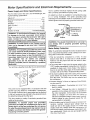
WARNING: To avoid electrical hazards, fire hazards
or damage to the tool, use proper circuit protection. Your saw is wired at the factory for 120v operation. Connect to a 120v, 15-amp, branch circuit
Have a qualified electrician replace the two prong outlet
with a property grounded three prong outlet.
An adapter as shown is available for connecting the plug
to a 2 prong receptacle. The green grounding lead
extending from the adapter must be connected to a permanent ground such as properly grounded outlet box.
Grounding Lug
3 Pron-
_
/
_
_==_MakeSureThisls
I_-_11 Connected to a
/
_
Adapter
oowo,,o00,
Receptacle
and use a 15-amp fuse or circuit breaker.
WARNING: To avoid shock or fire, if power cord is
worn, cut or damaged in any way, have it replaced
immediately.
WARNING: if not properly grounded this power toom
can cause electrical shock-particularly when used
in damp locations close to plumbing. If an electrical shock occurs there is also the potential of a
secondary hazard such as your hands contacting
the sawblade.
Not all outlets
are properly
grounded, if you are not sure that your outlet is
properly grounded, have it checked by a qualified
electrician.
Your unit has a plug that looks like the one shown below.
3-Prong
Plug
Properly
i WARNING: The adapter illustrated is for use only if
you already have a properly grounded 2-prong
receptacle.
Motor Safety Protection
Note: To avoid motor damage this motor should be blown
out or vacuumed frequently to keep sawdust from interfering with normal motor ventilation.
1. This tool should be connected to a 120v, 15 amp
branch circuit with a 15 amp fuse or circuit breaker.
Failure to use the proper size fuse can result in damage to the motor.
2. If the motor fails to start, turn the power switch to the
"OFF" position immediately. Unplug the tool. Check the
sawblade to make sure it turns freely. If the blade is
free, try to start the mot6r again. If the motor still does
not start, refer to the "Motor Troubleshooting Chart".
3. If the motor suddenly stalls while cutting wood, turn the
power switch off, unplug the tool and free the blade
from the wood. The motor may now be restarted and
the cut finished.
Grounded
Outlet
-,.,,
4. Frequent "blowing" of fuses or tripping of circuit breakers may result if:
a. Motor is overloaded - Overloading can occur if you
This power tool is equipped with a 3-conductor cord and
ground type plug listed by Underwriters' Laboratories.
The ground conductor has a green jacket and is attached
to the tool housing at one end and to the ground prong in
the attachment plug at the other end,
This plug requires a mating 3-conductor
)utlet as shown above.
WARNING:
whenever
grounded type
To maintain
proper
tool
grounding
the outlet you are planning to use for this
power tool is of the two prong type, do not remove
or alter ti_e grounding
prong in any manner. Use an
adapter as shown and always connect the grounding prong to known ground.
feed too rapidly.
b. Low Voltage - Although the motor is designed for
operation on the voltage and frequency specified on
the motor nameplate, normal loads will be handles
safety on voltages not more than 10% above or
below the nameplate voltage. Heavy loads, however,
require voltage at motor terminals equals the voltage specified on nameplate.
5. Motor troubles may be traced to loose or incorrect connections, overload, reduced input voltage (such as
small size wire in the supply circuit) or to overly long
supply circuit wire. Always check the connections, the
load and the supply circuit whenever motor fails to perform satisfactorily. Check wire size and length with the
Wire Size Chart below.
Motor Specifications and Electrical Requirements (continued)
Wire Sizes
The use of any extension cord will cause some loss of
power. To keep this to a minimum and to prevent overheating and motor bum-out, use the table below to determine the minimum wire size (A.W.G,) extension cord.
Use only 3-wire extension cords which have 3-prong
grounding type plugs and 3-pole receptacles which
accepts the tools plug,
CAUTION:
electrical
For circuits that are farther away from I
service
box, the wire size
must
be I
increased
proportionately
voltage to the
saw motor.
in order
to deliver
Length of the
Conductor
A.W.G.
0 -25 Ft.
26 - 50 Ft.
14
12
ample
Table of Contents
Warranty ........................................................................
2
Safety Instructions For Band Saw ................................ 2
Safety Signal Words: ................................................ 2
Before Using The Saw: ............................................. 2
When Installing Or Moving The Saw: ....................... 2
Before Each Use: ......................................................
2
Plan Your Work ..........................................................
3
Plan ahead to protect your eyes, hands, face.
and ears ..................................................................
3
Dress for safety .........................................................
3
Plan the way you will hold the workpiece
from start to finish ..................................................
3
Before Leaving The Saw...........................................
4
Glossary Of Terms For Woodworking ........................... 4
Motor Specifications and Electrical Requirements ....... 5
Power Supply and Motor Specifications ................... 5
Motor Safety Protection ............................................ 5
Wire Sizes .................................................................
6
Table of Contents ..........................................................
6
Unpacking and Checking Contents .............................. 7
Tools Needed ............................................................
7
Unpacking ..................................................................
7
Table of Loose Parts ................................................. 8
List of Loose Parts in Bag ........................................ 9
Assembly ....................................................................
10
Attaching Leveling Feet .......................................... 10
Assembling Leg Set ................................................ 10
Attaching Leg Set ...................................................
11
Adjusting Leveling Feet ........................................... 11
Mounting The Motor ...............................................
12
Mounting the Belt Guard .........................................
13
Mounting the Switch Box ........................................ 13
Mounting the Dust Chute ........................................
Mounting the Table Trunnion
..................................
Mounting the Table .................................................
Getting to Know Your Band Saw ................................
Alignments and Adjustments
......................................
Tilting the Table ......................................................
Adjusting 90 ° Table Stop ........................................
Changing Blades ....................................................
Adjusting Blade Tension .........................................
Adjusting Blade Tracking ........................................
Adjusting Upper Blade Guide Assembly .................
Adjusting Upper Blade Guides and
Blade Support Bearing .........................................
Adjusting Lower Blade Guides and
Blade Support Bearing .........................................
13
14
14
15
16
16
16
16
17
17
17
Safety Instruction for Basic Band Saw Operation
.......
Basic Saw Operations
................................................
General Cutting
......................................................
Circle Cutting ..........................................................
Maintenance
...............................................................
Tires ........................................................................
Adjusting the upper blade guide travel ...................
General Maintenance
.............................................
Motor ......................................................................
Lubrication ..............................................................
19
2!
21
21
22
22
22
22
22
22
18
18
Sears recommends
the following Accessories ........... 22
Troubleshooting-General
............................................
23
Troubleshooting-Motor
................................................
24
Repair Parts ..........................................................
26-29
J
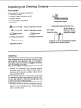
Unpacking and Checking
Contents
Tools Needed
Tools required for assembly and alignment:
o Combination Square
• 10ram and 14mm combination
wrench
Adjustable wrench.
• #1 and #2 Phillips screwdrivers
Combination
o Straightedge
#1 Phillips Screwdriver
lOmm Combination
Wrench
14ram Combination
Wrench
#2 Phillips
Combination
Draw Light
Line on Board
Along this Edge
Square
Square Must be True
_ _
Straight Edge of
Board 314" Thick
This Edge Must be
. Perfectly Straight
Screwdriver
Should be no Gap or Overlap when Square
is Flipped Over in Dotted Position
Adjustable Wrench
Unpacking
WARNING: To avoid injury from unexpected starting or electrical shock, do not plug the saw in until
all assembly and alignment steps are complete.
The power cord must remain unplugged whenever
you are working on the saw.
Unpacking and Checking Contents
1 Separate all "loose parts" from packaging materials
and check each item with "Table of Loose Parts" to
make sure all items are accounted for, before discarding any packing material.
WARNING: if any parts are missing, do not attempt !
to assemble the band saw, plug in the power cord, I
or turn the switch on until the missing parts are I
obtained and are installed correctly.
]
2. Sometimes small parts get lost in packaging materials.
Do not throw away any packaging until your saw is put
together. If your are missing a part, check packaging
before contacting Sears.
7
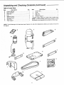
Unpacking and Checking Contents (continued)
-
-
Table of Loose Parts
Item
A
B
C
D
E
F
G
H
Item
Description
Qty.
Owners Manual ................................................... 1
Motor w/Switch ...................................................
1
Band Saw ...........................................................
1
Leg ......................................................................
4
Stiffener (Long) ................................................... 2
Stiffener (Short) .................................................. 2
Stand Top ............................................................
1
Plate Support ......................................................
1
Qescription
Qty.
I
Cover Pulley .......................................................
1
J
V-Belt ..................................................................
1
K
Bag Asm .............................................................
*
L
Table Asrn ...........................................................
1
M
Trunnion Support ................................................
1
* Number varies: bags can contain other smaller bags.
NOTE: To make assembly easier keep contents of each
bag together and separate from contents of other bags.
NOTE: To avoid damage to the band saw leave it laying on its side in the shipping box until you are ready to mount it to
the leg set.
D
A
C
E
G
H
j
M
8
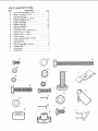
List of Loose Parts in Bag
totem
A
B
C
D
E
F
G
H
J
K
L
M
N
0
P
Q
R
S
T
U
Description
Qty
Screw Pan Head M5 x 0.8-12 ............................. 5
Washer Flat M5 x 10 Dia.
6
Nut Hex Head M5 ................
3
Bolt Hex Head M8 x 1.25-35 ............................ 10
Washer Flat M8 x 18
56
Rubber Grommet ................................................
4
Washer Lock M8 ..............................................
50
Nut Hex Head M8 .............................................
49
Washer Ext. M5 ..................................................
2
Screw Pan Head Lock M6 x 1-8 ......................... 2
Wrench Hex "L" - 3mm .......................................
1
Wrench Hex "L"- 5ram .......................................
1
Knob Locking ......................................................
2
Screw Hex Head M8 x 1.25-80 .......................... !
Foot Leveling ......................................................
4
Nut Hex 3/8-16 ...................................................
8
Bolt Carriage M8 x 1.25-16 .............................. 40
Clamp Cord ........................................................
1
Dust Chute .........................................................
1
Switch Key ..........................................................
1
O
Z
L
M
R
F
U
N
Assembly ......
Attaching
Leveling
Feet
1_ From the loose parts find the following items:
Item
A
B
Description
Qty.
Levelingfeet ........................................................
Hex nut 3/8-16 ....................................................
4
8
From the loose parts find the following items:
C
Leg......................................................................
4
2. Put a hex nut on each of the leveling feet and screw it
down towards the rubber foot.
3, Put the leveling feet through the holes in the bottom of
each leg.
4. Put another hex nut on each of the leveling feet and
hand tighten until they are next to the bottom support
of the leg.
C
B
WARNING: After the band saw has been attached
to the legset, it will be necessary to adjust the leveling feet so the saw does not rock.
A
Assembling
B
Leg Set
1. From the loose parts bag find the following hardware:
Item
A
B
C
D
Description
Qty.
M8 x 1.25-16 carriage bolts .............................. 40
M8 washers ......................................................
40
M8 Iockwashers ................................................ 40
M8 nuts .............................................................
40
F
From the loose parts find the following items:
E
F
G
H
Legs (with attached leveling feet) .......................
Stiffeners (short) .................................................
Stiffeners (long) ..................................................
Stand top ............................................................
G
4
2
2
1
B
2. Place stand top upside down on a level surface. Fasten
four legs to top using carriage bolts, washers, lock
washers, and nuts, as shown. Note: Legs fasten to
outside of top. Do not tighten at this time.
C
D
A
G
3. Fasten two long stiffeners and two short stiffeners to
stand legs using carriage bolts, washers, Iockwashers.
and nuts, as shown. Finger tighten only at this time.
F
H
10
4. Turn assembly over onto the legs. Be sure all four feet
sit flat on the ground. Adjustment of the feet will be
completed after the band saw is attached to the stand.
5. Tighten all stand fasteners at this time.
6. With the aid of a second person, lift the saw body out
of the shipping container and place onto the stand top.
Be sure front of saw faces stand front by aligning
holes.
o
O
O
CAUTION: Saw body is heavy! Use care when lift-_
ing and stabilize until it is firmly attached to the I
stand!
/
A
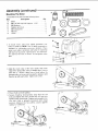
Attaching
Band Saw to Leg Set
1. From the loose parts bag find the following hardware:
Item
A
B
C
D
M8
M8
M8
M8
Description
Qty.
x 35 hex head bolts (approx. 1-3/8") ............. 4
washers ........................................................
8
Iockwashers ..................................................
4
nuts ...............................................................
4
D
2. Line up holes in saw body with holes in stand.
3. Place support
shown.
plate to the underside
of stand as
4. Fasten saw body, stand, and support plate together
with four hex head bolts, eight flat washers, four lockwashers, and four hex nuts.
B
C
Adjusting
Leveling
Lo0
Feet
WARNING: To avoid injury from unexpected saw or
work movement, leveling feet must be adjusted so
that saw does not rock.
Hex Nut
To adjust leveling feet so the saw will sit properly:
1. Move saw to desired location.
2. Raise or lower leveling foot by turning the nuts clockwise or counterclockwise.
3. Tighten nuts to lock leveling foot in place.
11
/
Assembly
Mounting
(continued)
.....................
B
The Motor
1, From the loose parts find the folk)w_ng l_m_v
Item
A
Motor
Description
..................................................
B
C
M8 x 35 hex cap botts (approx
M8 Washers ................
D
E
F
G
Rubber gremrnets
M8 _ockwast_ers
M8 nuts ................................
V Beit
Qty.
1
1.3/8°_
4
8
4
4
4
1
......
.............
....
2 ]o mount motor
piece four rubber grommets
over
holes _r_stand top NOTE Use of rubber grommets _s
essentia!
for eiirmnatinq
excesswe
vibrahon
Place
ii _
motor over rubber grommets
ahd fasten to stand top
with tour hex i_ead bolts eight washers
four tockwash
ers. and _'Ou_hex nuts. as shown Do not t_ghten _d this
hme
,-.
if ,
_.............
i_ _,_ o
_I .__i_-_-
3, ARign the tns_de edge of the motor pulley with inside
edge of the large pulley usin_;l a straight ed(,le Usinq a
3ram hex "L" wrench
adlust one or botl_ pulleys by
loosening the set screw and moving the pulley(s) unhl
they Sine up with each other Tighten set screws
r
i
1111
i
J t
,
rll
ill
i
i
ii,
u
•
4 Place V belt over both pulleys
5 Tension V belt by mowng moler away from tl_e saw
body and tighten the motor mount nuts (Do not over
tighten nqotor mount bolts Tighten just enough to ten
sion belt,} Belt is p_:operly tensioned
when linger
pressure
between
the two pulleys causes approxi
matety 1/2" deflection
1 v
12
L
;
Mounting
the Belt Guard
1. From the loose parts
Item
A
B
C
D
find the following
A
items.
Descr iption
Qty.
Belt guard ..........................................................
1
Screw pan head M5 x 0.8,-!2 (approx, !/2") ...... 3
M5 washers .......................................................
6
M5 nuts ...............................................................
3
i
2. Place belt guard over both pulleys and fasten to stand
using three pan head screws, six washers_ and three
hex nuts, as shown,
B_
C
i
Mounting
the
Switch
A
B
C
.....
Box
1. From the loose parts find the following
Item
,HHH
A
hardware:
Description
Qty.
Screw pan head M5 x 0.8,-12 (approx. 1/2") ....... 2
Lockwasher
Ext. M5 ...........................................
2
Clam E Cord ......................................
_
2, Mount switch box assembly
hardware listed.
to frame
3, Make sure
cord clamp.
cord
motor
& power
..................
as shown
are captured
1
...........
using
under
A
Mounting
the
Dust
1. From the loose parts find the following
Item
A
B
B
Chute
items:
Description
Dust Chute .........................................................
Screw pan head lock M6 x 1-8 ...........................
Qty.
1
2
2. Open lower blade guard cover and install dust chute.
Use fasteners
supplied.
Close lower blade guard
cover.
@
13
Assembly
(continued)
A
Mounting
the Table Trunnion
Support
From lhe _eose par_s find the following
items:
Description
_om
Qty.
M8 x 35 he× head bolts (approx. t--3/8 _) .............. 2
M8 Iockwashers ................................................
2
A
B
C
C
M8 x 80 hex cap bolt ...........................................
1
(table stop boll appro×. 3-1/8' long)
M8 nut dor table slop bolt) ...................................
t
Table lrur_nlon support (shown below} ................. 1
D
E
I
I
i
--
_,
2. Attach trunnion support to saw body with two hex head
bolls and two lockwashers
as shown
3, Thread nut (C) onto table
trunnion support.
E
' ' ' ["!"[(!!!["' '
II
Mounting
t,
I
stop bolt (D) and attach
IIIIi
.......
the Table
From the loose parts find the following
_em
A
items:
Description
A
B
!llq'
B
Qty.
Table
Knobs
[1111111
to
i
2
I
[
I
I
I'
I
IJ I I_
'
' IIII II" ii
,
I
2, To mount table, remove table insert and tat)le pin from
the tabte_ Guide sawblade
through slot in table and
place table screws into trunnions,. Attach and lock with
lock knobs,
WARNING:
Unit is shipped
with
blade
in stalled.
Do not plug in or operate
unit unless the blade
is adjusted
and aligned
per section titled
changing
blades.
3 Reptace
table insert and table pin,
4. Transportation
and handlirtg may have caused some
fasteners
to loosen.
Before
operating,
check
all
screws
bolts and nuts to make sure they are snug.
Operate machine only after reading the entire manual
including blade tracking, blade guide adjustments,
and
safety rules,
14
L
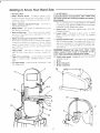
Getting to Know Your Band Saw ...........................
t, Warning Label
2. Blade
Tension
Knob _ Clockwise
rotation of fi_e
knob wilt increase the tensior_ on the blade. Counterclockwise rotation of the knob wJJt decrease the ten °
sion on the bIade.
10. On-Off
3. Blade
adjust
The On-Off Switch has a iocking feature. This feature
is intended to help prevent unauthorized
and possibte
hazardous use by children and others.
11. Upper Cover - Pull knob to expose upper whee_ during btade changes.
Tracking, Adjustment
blade tracking.
4. Blade Guides o The guides
full support ot the blade.
Knob
- RJrn knob
are adiustable
the blade guards are correctly instaiJed and operatCAUTION:
Before turning
switch
"ON",
make sure
ing properly.
to
to provide
5. Back-up
Bearings
_ These thrust bearings support
the back of the blade and are adi_stabte for the vari.
ous blade widths,
12. Lower
wheel,
9. Tilt Table Stops
45 ° index points.
Retighten
knobs
Cover - Pull knob to gain access to lower
remove the blade or to clean out sawdust
t3. Sawdust
Ejection
Port - Your band saw is equipped
with a vacuurn hookup
This feature witl allow you to
attach any standard 2-1/2 inch diameter wet/dry vacuum hose into the hole provided for convenient
sawdust removal.
7. Tilting
Table - Table ti_ts for angular cuts. Use the
tab!e ti!t sca!e _!nder tabie to measure angular settings.
8. Table Tilt Lock Knobs
--Looser_ knobs to move tilt
angle.
J
build-up.
6. Blade Guard Support
Adjustment
Knobs o Loosen
this knob to vertically adiust the blade guard support
so that it just clears the workpiece to be cut. A!ways
adjust the guard/support
belore turning ot_ the [:!aI_d
saw. Tighten the knob to lock the guard/support
in the
proper location.
table to required
table.
Switch
WARNING:
Sawdust
can clog motor.
Motor could I
ignite sawdust.
Even if saw is connected
to vacuum, blow out sawdust
regularly from motor.
14. Lower blade guard
tat blade contact,
to secure
Safeguards
user from
acciden-
15_ Motor
- Adjust
stops for" convenient
0 ° a_qd
16. Motor belt
17. Model
guard.
nameplate.
16
7
8
15
17
13
15
Alignments and Adjustments
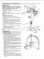
Tilting the Table
source before making any repair or adjustment.
I Failure
ARNING:
Unplug may
thecause
machine
from
the power t
to comply
serious
injury.
1, Loosen two lock knobs,
2. Tilt table up to 45 degrees to the right or up to 10 ° to
the left.
3. Tighten two lock knobs.
NOTE: 90° table stop must be removed to tilt table 10° to
the left.
Adjusting
90 ° Table Stop
Lower
1. Disconnect machine from the power source.
2. Loosen lock knobs and tilt table left until it rests against
table stop.
3. Use a square placed on the table and against the
blade to see if the table is 90 degrees to the blade.
Rotating
Blade Guard
4. If an adjustment is necessary, loosen lock knobs. Tilt
table to the right, and lock in place.
5. Loosen jam nut and turn table top left or right to raise
or lower the stop. Tighten jam nut to hold table stop n
place,
6. Unlock table, tilt back onto table rest and confirm table
is 90 degrees with the blade.
7. If necessary, adjust pointer to zero.
NOTE: 90 ° table stop must be removed to tilt table 10° to
the left.
Changing
Table
\
I
Blades
'CAUTION:
Blade teeth are sharp.
handling the sawblade.
Use care when I
Table Insert
]
1. Disconnect the machine from the power source.
2, Loosen blade tension by turning blade tension knob
counter-clockwise until it stops.
3. Remove the table insert and the table pin.
4. Open upper and lower cover. Remove screws and
washers from guard blade rear. Then remove guard.
5. Insert screwdriver through table insert hole to loosen
pivot screw one turn for guard under the table. Rotate
guard out of the way.
6 Remove the blade from between upper and lower
blade guides. Remove blade from upper and lower
wheels. Turn blade so it will fit through slot in table.
Remove blade.
7. Guide new blade through table slot. Place blade in
upper and lower blade guides. NOTE: Make sure
blade teeth point down toward table.
8. Place blade in the middle of the upper and lower
wheel.
9. Replace guard blade rear and tighten screws.
10. Rotate guard under table to a closed position and
tighten screw.
11. Replace table insert and table pin.
12. Tension and track blade before operating saw. Find
instructions for tensioning and tracking the blade
under "Adjusting Blade Tension" and "Adjusting Blade
Tracking".
16
Pin
Adjusting
Blade Tension
1. Disconnect machine from the power source.
2. Turn blade tension knob clockwise to tension blade. A
gauge on the upper wheel slide bracket indicates the
approximate tension according to the width of the
blade. Initially, set the blade tension gauge to correspond with the blade width.
3, As you become familiar with the saw, you may find it
necessary to change the blade tension from the initial
setting. Changes in blade width and the type of material being cut will have an effect on blade tension.
4. Keep in mind that too little or too much blade tension
can cause blade breakage.
Adjusting
Blade
Tension
Blade Tracking
Gauge
source. Never adjust
machine running.
blade
tracking
with
the
1. Blade must be properly tensioned before adjusting
blade tracking. Make sure blade guides and blade
bearings do not interfere with the blade.
2. Open upper cover. Rotate the wheel forward by hand
and observe the position of the blade on the wheel. It
should be in the center.
3. If adjustment is necessary, loosen wing nut, tighten
knob slightly to move blade toward rear of machine.
Slightly loosening the knob will cause the blade to
track toward the front of the machine.
4. Tighten nut after blade is tracking in the center of the
wheel.
Adjusting
Upper
Blade Guide Assembly
1. Disconnect machine from the power source.
2. Loosen lock knob and raise or lower upper blade guide
assembly to just above the material being cut.
3. Tighten lock knob. Make sure blade guide blocks are
still flat to the blade. If adjustment is necessary, loosen
lock knob and rotate assembly until guide blocks are
flat to the blade.
4. The upper blade guide is spring loaded. To adjust the
tension on the spring, remove knob, tighten or loosen
set screw until desired tension is reached, and replace
knob.
17
Alignments and Adjustments
(continued)
_
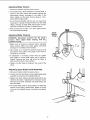
Adjusting Upper Blade Guides and Blade
Support Bearing
WARNING: Blade guard has been removed for pic- I
lure clarity. Never operate the band saw without all
guards in place and in working order, Failure to
comply may cause serious injury.
I
1. Disconnect machine from the power source.
2. Blade must already be tensioned and tracking properly.
3. Loosen thumb screws and move guide blocks as close
to the blade as possible without pinching it. The thickness of a dollar bill on each side of blade is a good rule
of thumb.
7
4. Tighten thumb screws.
5. Loosen thumb screw and turn knurled knob to move the
guide block bracket in or out until the front edge of the
guide blocksare just behindthe "gullets" of the saw teeth.
6. Tighten thumb screw.
7. Loosen thumb screw and turn knurled knob to move
the support bearing in or out until the bearing is !/64"
behind the blade.
Step 3
Step 5
8. Tighten thumb screw.
9, Blade support bearing should be adjusted so that the
back edge of the blade overlaps the front face of the
ball bearing approximately 1/8". To change position of
the bearing, remove screw bearing, and back of!
knurled knob completely to remove the bearing shaft.
Notice the bearing holder on the shaft is eccentric. Reinstall the bearing shaft, the bearing, and the screw.
Examine the overlap between the bearing face and the
blade. Change the position of the bearing shaft until
the overlap is approximately 1/8"
Adjusting
Lower Blade Guides
Suppport
Shaft
_Blade
Step 9 (upper and lower)
and Blade
Support Bearing
1. Disconnect machine from the power source.
2. Blade must already be tensioned and tracking properly.
3. Loosen thumb screws and move guide blocks as close
to blade as possible without pinching it. The thickness
of a dollar bill on each side of blade is a good rule of
thumb.
4. Tighten thumb screw,
5. Loosen thumb screw and move the guide block support in or out until the front edge of the guide blocks
are just behind the "gullets" of the saw teeth.
6 Tighten thumb screvy,
7. Loosen thumb screw and move the support bearing in
or out until it is 1/64" behind the sawblade
8. Tighten thumb screw.
9. The blade support bearing should be adjusted so that
the back edge of the blade overlaps the front face of
the ball bearing approximately 1/8". To change position
of the bearing, remove screw and bearing. Loosen
thumb screw and remove the bearing shaft. Notice the
bearing holder on the shaft is eccentric. Re-install the
bearing shaft, the bearing, and the screw. Examine the
overlap between the bearing face and the blade.
Change the position of the bearing shaft until the overlap is approximately 1/8".
18
Safety instructions
Before
for Basic Band Saw Operation
o Replace damaged or missing parts before using the
saw again.
Using The Saw:
I
ous, permanent injury, do not plug the saw in until
I the
WARNING:
avoid have
mistakes
could cause seri- J
following to steps
been that
completed.
• Completely assemble and align saw (see "Assembly"
and "Alignment" section within).
• Learn the use and function of the ON-OFF switch,
bevel handwheel, bevel lock knob, blade guides,
backup bearings, guide bar lock knob and blade guard.
• Review and understand all safety instructions
operating procedures in this manual.
• Review the maintenance methods for this saw.
To avoid injury from jams, slips or thrown
broken blades.
and
pieces or
Inspect your blade.
° Choose the right blade size, style and cutting speed for
the material and the type of cutting you plan to do.
Use only recommended accessories.
Consult this
owners manual for recommended accessories. Follow
the instructions that come with the accessories. The
use of improper accessories may cause risk of injury to
persons.
Or Moving The Saw:
Avoid dangerous environment.
• Use the saw in a dry, indoor place protected from rain.
Make sure the blade teeth point downward, toward the
table.
• Keep work area well lighted.
To avoid injury from unexpected saw movement.
° Put the saw on a firm level surface where there is
plenty of room to handle and properly support the
workpiece.
• Make sure the blade guides and thrust bearings
properly adjusted.
are
• Make sure the blade tension is properly adjusted.
o Make sure the bevel clamp is tight and no parts have
excessive play.
°To avoid accidental blade contact, minimize blade
breakage and provide maximum blade support, always
adjust the upper blade guide and blade guard to just
clear the workpiece.
• Support the saw so the table is level and the saw does
not rock.
• Bolt the saw to the floor or work surface if it tends to
slip, walk or slide during operations like cutting long,
heavy boards.
• Turn saw off and unplug cord before moving the saw.
Inspect your work area.
To avoid injury from electrical shock.
• Make sure your fingers do not touch the plug's metal
prongs when plugging in or unplugging the saw.
• Keep work area clean.
• Cluttered areas and benches invite accidents. Floor
must not be slippery from wax or sawdust.
To avoid back injury.
=To avoid burns or other fire damage, never use the saw
near flammable liquids, vapors or gases.
• Get help or use recommended casters when you need
to move the saw. Always get help if you need to lift the
saw.
Plan your work.
° Use the right tool. Don't force tool or attachment to do
a job it was not designed to do.
° Use this band saw to cut only wood, wood like products and plastics.
CAUTION: To avoid blade breakage, fire or other
damage to the saw, NEVER use this band saw to
cut metals.
• Never stand on tool, Serious injury could occur if the
tool tips or you accidentally hit the cutting tool. Do not
store any items above or near the tool where anyone
might stand on the tool to reach them.
Before
• Maintain tools with care. Keep the saw clean for best
and safest performance. Follow instructions for lubricating.
o Remove adjusting keys and wrenches. Form a habit of
checking for and removing keys and adjusting
wrenches from table top before turning it on.
o Find and read all the warning labels found on the front
of the saw (shown below).
When Installing
--
Each Use:
Inspect your saw.
° To avoid injury from accidental starting, turn the switch
off, unplug the saw, and remove the switch key before
changing the setup, removing covers, guards or blade.
• Check for alignment of moving parts, binding of moving
parts, breakage of parts, saw stability, and any other
conditions that may affect the way the saw works.
• Know your saw, Read and understand the owner's
manual and labels affixed to the tool. Learn its application and limitations as well as the specific potential
hazards peculiar to this tool.
• To avoid injury from accidental contact with moving
parts, don't do layout, assembly, or set up work on the
saw while any parts are moving.
• If any part is missing, bent or broken in any way, or any
electrical part does not work properly, turn the saw off
and unplug the saw.
° Avoid accidental starting. Make sure switch is "OFF"
before plugging saw into a power outlet.
19
Safety instructions for Basic Band Saw Operation
Plan ahead to protect your eyes, hands, face
and ears.
WEAR
(continued)
Plan the way you will hold the workpiece
from start to finish.
• Do not hand hold pieces so small that your fingers will
go under the blade guard. Use jigs or fixtures to hold
the work and keep your hands away from the blade.
YOUR
° Secure work. Use clamps to hold work when practical.
It's often safer than using your hand, and frees both
hands to operate the tool.
• Don't overreach. Keep good footing and balance.
Whenever
Dress for safety
Sawblade
Is Spinning:
WARNING: Don't allow familiarity (gained from frequent use of your band saw) cause a careless mistake. Always remember that a careless fraction of a
second is enough to cause a severe in)ury.
Any power saw can throw foreign objects into the eyes.
This can cause permanent eye damage. Wear safety
goggles (not glasses) that comply with ANSI Z87.1
(shown on package). Everyday eyeglasses have only
impact resistance lenses. They are not safety glasses.
Safety goggles are available at Sears retail catalog
stores. Glasses or goggles not in compliance with ANSI
Z87.1 could seriously hurt you when they break.
• Before starting your cut, watch the saw while it runs. If
it makes an unfamiliar noise or vibrates a lot, stop
immediately. Turn the saw off. Unplug the saw. Do not
restart until finding and correcting the problem.
Keep Children Away,
° Keep all visitors a safe distance from the table saw.
• Do not wear loose clothing, gloves, neckties or jewelry
(rings, wrist watches). They can get caught and draw
you into moving parts.
° Make sure bystanders are clear of the table saw and
workpiece.
Don't Force Tool
- Wear nonslip footwear.
° Tie back long hair.
° Roll long sleeves above the elbow.
° Let the blade reach full speed before cutting.
• Noise levels vary widely. To avoid possible hearing
damage, wear ear plugs or muffs when using saw for
hours at a time.
° It will do the job better and safer at its designed rate.
° Feed the workpiece into the saw only fast enough to let
the blade cut without bogging down or binding.
° For dusty operations, wear a dust mask along with the
safety goggles.
Before freeing jammed material.
• Turn switch "OFF".
Inspect your workpiece.
• Unplug the saw.
Make sure there are no nails or foreign objects in the
part of the workpiece to be cut.
Use extra caution with large, very smanl or awkward
workpieces:
• Wait for all moving parts to stop.
• Remove switch key.
When backing up the workpiece, the blade may bind
in the kerr (cut). This is usually caused by sawdust
clogging up the kerf or because the blade comes out
of the guides, if this happens:
• Turn saw "OFF".
• Use extra supports (tables, saw horses, blocks, etc.)
for any workpieces large enough to tip when not held
down to the table top.
• NEVER use another person as a substitute for a table
extension, or as additional support for a workpiece that
is longer or wider than the basic saw table, or to help
feed, support or pull the workpiece.
° Wait for all moving parts to stop.
• Remove switch key.
• When cutting irregularly shaped workpieces, plan your
work so it will not slip and pinch the blade. A piece of
molding for example, must lie flat or be held by a fixture
of jig that will not let it twist, rock or slip while being cut.
• Properly support round material such as dowel rods, or
tubing. They have a tendency to roll during a cut,
causing the blade to "bite". To avoid this, always use a
"V" block or clamp the work to the miter gage.
• Stick flat blade screwdriver or wedge into the kerr.
• Unplug the saw.
° Remove band saw cover.
° Turn the upper wheel by hand while backing up the
workpiece.
Before removing loose pieces from the table, turn saw off
and wait for all moving parts to stop.
• Cut only one workpiece at a time.
-Clear everything except the workpiece and related
support devices off the table before turning the savJon.
2O
o Make workshop child-proof.
Before Leaving The Saw.
- Lock the shop.
- Disconnect master switches.
• Turn the saw off.
o Wait for all moving parts to stop.
- Remove the yellow switch key. Store it away from
children and others not qualified to use the tool.
• Unplug the saw.
Basic Saw Operations
Operation
General Cutting
safety instructions
on pages 2-5 before using the
I CAUTION:
band saw. For your safety, compay with all the
A band saw is basically a "curve cutting" machine. It is
not capable of doing inside cutting.
It is also used for straight-line cutting operations such as
crosscutting, ripping, mitering, beveling, compound cutting and resawing.
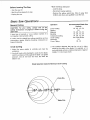
Circle
Recommended Blade Size
(Inches)
Cross Cutting
Ripping
Mitering
Beveling
Compound Cutting
Circle Cutting
Resawing
Curve Cutting
1/4, 3/8, 1/2, 3/4
3/4
1/4, 3/8, 1/2, 3/4
1/4, 3/8, 1/2, 3/4
1/4, 3/8, 1/2, 3/4
See Chart Below
3/4
1/8, 1/4
3. The smallest diameter that can be cut out is deter-
Cutting
mined by the width of the blade. For example, a 1/4inch wide blade will cut a minimum diameter of approx-
1. Adjust the upper guides to vertically just clear the
workpiece.
2. Use both hands while feeding the work into the blade.
Hold the workpiece firmly against the table. Use gentle
pressure, and do not force the work, but allow the
blade to cut.
imately 1-1/2-inch (see chart).
Blade Selection Guide for Minimum Circle Cutting
rcie
7"D
1/2"Blade
21
1
3f4"
Maintenance -----
..........
turn SW_tCh
I WARNING:
For
your
own
safety,
and remove plug from power source outlet before
maintaining
or lubricating your band saw,
Tires
Pitch and sawdust that build up on the tires should be
removed w_h a stiff brush or scrape off with a piece of
vvood
NOTE: Td avoid damaging
k_'_ifeor any kind of solvent,
the tires do not use a sharp
When the tires become worn they should be replaced,
When replacing the tires, stretch them around the wheels
but do not glue them on.
Adjusting
the
upper
blade
guide
travea
General Maintenance
Keep your band saw clean. Remove the sawdust
the inside Vacuum or blow out frequently.
Do not allow fiSth to build up on the table the guides or the
back-up bearings. Clean them with Craftsman
Gum and
Pitch Remover.
NOTE: Do not immerse
bearings
in the gum
Put a thin coat of paste wax on the table so that the wood
slides easily while cutting.
Motor
Frequently
blew or vacuum out any sawdust from the
motor, Follow lubrication
instruction on the motor label.
CAUTION: To avoid eye injury from blowing
debris,
wear safety goggles when blowing
out sawdust.
merit shouk_J be performed.
WARNING:
the guide bar lock knob.
ately replace
2. Using a 5ram he× "L" wrench, tighten or loosen
screw which is tocated below the lock knob.
the back-up
and pitch remover,
if the upper guido bar will not move up and down easily or
fails when the lock knob is loosened, the following adjust-
! Remove
from
To avoid electrocution
a worn, cut or damaged
or fire,
power
immedicord.
the
3, Move the guide bar up and down to check for smooth
mevement
while
still
holding
its
position
when
released
Lubrication
All of the ball bearings are packed with grease
tory, They require no further lubrication.
at the fac-
4. Make further adjustrnents
to the screw as required to
get the guide bar to move smoothly and hold its position when released,
5, Reinstall
guide bar lock knob_
Sears Recommends
the Following
Cool Blocks ............................................
See Catalog
Miter Gauge ...............................................
,:. :.9_29929
Hold,-,Down Clamp for Miter Gauge.
......... ::
9-29928
Stops, Rods for Miter Gauge .............................
9-29924
Blades .............................................................
See Catalog
Accessories
Sears may recommend
the manual. See your
accessories.
Do not use any accessory
read complete instructions
22
-other accessories
not listed in
nearest
Sears store for other
unless you have received
for its use.
and
Troubleshooting-Genera!
WARNING:
For your own safety, turn
shooting your band saw/sander.
Trouble
T
I
............................
switch
Probable
"Off"
and remove
Cause
plug
from
power
1
source
outlet
before
trouble
Remedy
+
Blade does not run in the
_.
approximate
upper wheel
,_
i
center of the
Band Saw slows down when
cutting
Not tracking
preperty.
1, Adjust tracking
i I. Belt too loose.
2. Cutting too small a radius,
13. Dull blade,
i4. Overloading
motor,
1
braking
1, Blade guides set too ck)se
!
to teeth,
2. Cutting
Band saw vibrates,
'Installing
the
'
!. Adjust belt tension, see "Assembly" section, "Installing and Aligning the Belt",
2, Stop feeding, and back up the material sIJghtty until
the band saw speeds up.
Replace blade.
Slow down, trying to cut too fast.
4,
t. ]-oo much tension on
blade.
2, Kink in blade caused cut °
ting too small a radius or
turning the material too
fast when cutting.
Blade dulls too quickly.
Sectk)n
Blade",
{
tBlades
see Assembly
incorrect
1 Too much tension
motor belt
1. Adjust tension. See "Getting to Know Your Band
Saw".
See "Basic Band Saw
2. Use correct cutting technique.
Operation"
section_
1Adjust upper and lower blades guides.
bly" section "Installing
See 'Assem-
the blade".
material
on
1. Adjust according
Belt" section.
23
to "Installing
and Aligning
Poly "V"
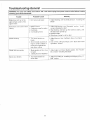
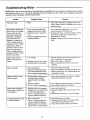
Troubleshooting-Motor
NOTE: Motors used on wood-working tools are particularly susceptible to the accumulation of sawdust and wood chips
and should be blown out or "vacuumed" frequently to prevent interference with normal motor ventilation and proper
operation of the centrifugally-operated
starting switch.
Probable Cause
Trouble
RellNedy
Excessive noise
1. Motor
1. Have motor checked by qualified service technician. Repair service is available at your nearest Sears store.
Motor fails to develop full
power. Note Low Voltage:
Power output of motor
decreases rapidly with
decrease in voltage at
motor terminals. For
example, a reduction of
10% in voltage causes a
reduction of 19% in maximum power output of
which the motor is capable, and a reduction of
20% in voltage causes a
reduction of 36% in maximum power output
1. Circuit overloaded with light,
appliances and other motors.
2. Undersize wires or circuit too
long.
3. General overloading of power
company facilities.
1. Do not use other appliances or motors on
same circuit when using the saw.
2. Increase wire sizes, or reduce length of wiring.
See "Motor specifications and Electrical
Requirements" section.
3. Request a voltage check from the power company.
Motor starts slowly or
fails to come up to full
speed.
1. Low voltage.
1. Request voltage check from the power company. Check size of circuit wiring.
2. Have motor repair or replaced.
3. Blow out sawdust from motor. Have motor
repaired.
Motor overheats
1. Motor overloaded.
2. Windings burned out or open.
3. Starting switch not operating.
2. Improper cooling (air circulation restricted through motor
due to sawdust accumulation).
1. Feed work slower into blade.
2. Clean out sawdust to provide normal air circulation through motor. See "Maintenance and
Lubrication" section.
1. Burned switch contacts (due to
extended hold-in periods
caused by low line voltage,
etc.)
2. Shorted capacitor.
3. Loose or broken connections.
1. Have switch replaced and request a voltage
check from the power company.
Motor stalls (resulting in
blown fuses or tripped circuit breakers).
1. Starting switch not operating.
2. Voltage too low to permit motor
to reach operating speed.
3. Fuses or circuit breakers do
not have sufficient capacity.
1. Have switch replaced.
2. Request voltage check from the power company.
3. Install proper size fuses or circuit breakers.
Frequent opening of fuses
or circuit breakers.
1. Motor overloaded.
2. Fuses or circuit breakers do
not have sufficient capacity.
3. Starting switch not operating
(motor does not reach speed).
1. Feed work slower into blade.
2. Install proper size fuses or circuit breakers.
Check that wiring will handle load.
3. Have switch replaced. Blow out sawdust.
Starting switch in motor
will not operate.
24
2. Have capacitor tested and replace if defective.
3. Have wiring checked and repaired.
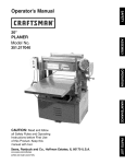
SWITCH
MOTOR
r
"!
I
I
I
WHJTE_
IGREEN
WHITE
I
1
MOTOR
LEAD
I
_1_
BLACK
_t
t
I
I
MOTORLEAD
--J
POWER CORD ------J
TO SWITCH
I
L
-- j
Circuit
Diagram
25
L--POWER
SWITCH
CORD
TO MOTOR
Parts
List For Craftsman
Model
14-inch
Band
Saw
No. 113,248-340
Figure 1
95
94
102
//
9i
87
39
85
\
84
\
80
102
97
39
106
83
50
65
75
)
64
\
74
8O
5t_-_
58
\
57
83
43 j
60
49
73
\
79
71
73
30
\
63
68
72
74
81
58
69
77
78
51
20
19
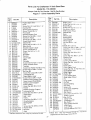
Parts List For Craftsman
Model
14 inch Band Saw
No. 113.248340
Always Order By Part Number - Not By Key Number
Figure
1 - Drive Assembly
Key
No.
Description
Y.
3
4
6
8
9
10
11
12
13
14
15
16
17
18
19
2O
21
22
23
24
25
26
27
28
29
30
31
32
33
3,
3
36
37
38
39
4O
41
42
43
45
47
48
49
5O
51
52
53
54
Part No.
1823746
0824
3574
3744-1
823575
823601
823954
823573
820249-4
823596
STD851006
813307-3
823572
823745
823744
821750
823743
823742
813249-76
823580
823559
823579
823769
823565
823586
823768
STD835080
56-100005
816755-4
STD852005
823588
STD833020
823602
823750
823779
823541
813313-5
823578
823587
STD852008
STD835040
82356O
817393-5
823585
817391-1
816782
81753O
823741
821732-1
STD851016
STD841620
823756
* Standard
hardware
,k
Frame Upper Arm
Knob
Screw Pan Hd. Lock M6 x 1-!2
Bearing Ball
Sleeve Upper Spacing
Screw Thumb M6-16
Post Guide
Bracket Support Post
Screw Soc Set M8 x 1.0-40
Nut Micro-Adjust
Screw hex Hd. M6 x ! .0-16
Guard Blade Upper
Washer M6
Screw Hex Hd. M6x 1.0-10
Block Guide
Bracket Support Upper
Screw Thumb M6-12
Screw Set MIO x 1.5-10
Spring
Ball Steel
Pin Roll
Insert Table
Table
Pin table
Screw Hex Hd. M10 x 1.5-55
Clamp Trunnion Shoe
Trunnion
Screw hex Washer hd. M6 x 1-12
Screw Hex hd. M8 x 1.25-80
Nut Hex M8
Screw Pan Cross M5 x 0.8-8
Lockwasher M5
Guard Blade Lower
Screw Hex hd. M6 x 1.0-20
Bracket Lower Support Post
Guard Lower Wheel Blade
Bracket Lower Support
Knob Locking
Screw Pan Hd. M5 x 0.8-6
Pointer
Bracket Trunnion Support
Lockwasher M8
Screw Hex Hd. M8 x 1.25-35
Scale Bevel
Belt V A40
Pulley
Screw Soc Set M6 x 1.0-10
Ring Retaining
Bearing Ball
Pin
Screw Hex Hal. M16 x 2.0-55
Washer M16
Nut M16
Stud
item, May be purchased
55
56
57
58
59
6O
61
62
63
64
65
66
67
68
69
7O
71
72
73
74
75
76
77
78
79
80
81
82
83
84
85
86
87
88
89
9O
:91
92
93
94
95
96
97
98
99
10(
!0
10;
10,'
lOz
10._
10(
Parts
Part No.
823598
818470-3
823555
813313-4
819188
823584
STD851008
823554
823556
823762
823761
823550
823763
823595
9-27193
823753
823751
823583
817357
823582
813310-5
823581
823558
823557
823771
823760
823553
823764
816069
823600
823597
STD821005
823758
823571
823569
823568
813249-104
823594
823570
823549
823754
823567
823755
STD510603
60267
9-22255
63418
STD852005
823547
823546
823543
823563
SP5836
Description
-q
Hinge L_-Screw Flat Hd. M5 x 0.8-10
Brush Wheel
Screw Pan Hd. M5 x 0.8-12
Key 5ram x 20ram
Shaft Lower Wheel
Washer M8
Base
Wheel Lower
Bearing Ball
Ring Retaining
Wheel Upper
Nut Hex M12 x 1.25
Tire
1 Blade 3/8 x 93-1/2
Screw Hex Hd. LH M8 x 1.25-25
Bolt M!0 x 1.5-15 (Special)
Catch Door
Screw Pan Hd. M4 x 16-8
Clip Door
Screw PanHd. M8 x 1.25-16
Bracket Door
Chute Dust
Cover Lower Wheel
Screw Pan Hd. Lock M6 x 1-8
Washer
Knob Catch
Cover Upper Front
Screw Pan Hd. Ty "AB" #6 x 5/8
Guard Blade Rear
Hinge Upper
Washer M5
Cover Upper Back
Shaft Upper Wheel
Pin
Hinge Shaft
Pin Roll
Bracket Sliding
Nut Wing
Knob Lock
Knob Blade Adjusting
Spring Coil
Nut Square
* Screw Pan Hd. #6-32 x 3/8
Switch Locking
t Key, Switch
Clamp Cord
Lockwasher M5
Box Switch
Plate Switch Backing
Cord Power
Cord w!Plug
Owners Manual (Not Illus.)
1 Stock Item - May be sec_
h tile Hardware
Department of most Sears Retail Stores.
locally.
27
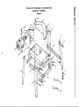
Parts List For Craftsman
14 inch Band Saws
Model No. 113.248340
Figure 2
_l=l I
24
23
4
/
2O
/
ro
Go
14
16
3
9
4
5
14
11
6
5
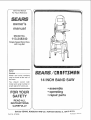
Parts List For Craftsman
Model
14 inch Band Saw
No, 113.248340
Figure 2 - Base Components
Always order by Part Number - Not by Key Number
Key
No.
1
2
3
4
5
6
7
8
9
10
11
12
13
Part No.
823592
813313-4
STD851005
823773
823590
823776
STD541237
803835-1
STD840508
STD840812
STD852008
STD851008
823593
Key
No.
Description
Cover Pulley
Screw Pan Hd. M5 x 0.8-12
* Washer M5
Leg
Stiffener Long
Bolt Carriage M8 x 1.25-16
* Nut Hex 3/8-16
*
*
*
*
14
15
16
17
18
19
20
21
22
23
24
25
26
Foot Leveling
Nut Hex M5
Nut Hex M8
Lockwasher M8
Washer M8
Plate Support
* Standard hardware item. May be purchased locally.
29
Part No.
823589
823774
823747
823562
STD835040
!817391-1
823740
819188
823576
823591
817357
813317-6
813317-7
Description
Stiffener Short
Stand Top
Grommet Rubber
Motor
Screw Hex Hd. M8 x 1.25-35
Screw Set M6 x 1.0-10
Pulley Motor
Key 5ram x 20mm
Pad
Cover pulley Inner
Screw Pan hd. M4 x 16-8
Wrench Hex "L" 3mm
Wrench Hex "L" 5mm
_0
Notes
.......
31
14 iNCH
Model No,
113,248340
Single Speed Band Saw
with Leg Set
For _he repair or replasement pat_syou need
Call 7 am - 7 pm, 7 days a week
1-8OO-,366=PART
(1-800-365-7278)
The model number of your 14
inch Band Saw will be found
on a plate attached to your
saw, on the back side of the
upper cover.
For in-home major brand repair service
Call 24 hours a day, 7 days a week
t-8OO-4,.R6PAJR
(1-800-473-7247)
When requesting service or
ordering parts, always provide
the following information:
• Product Type
• Model Number
Far the location of a
Sears Repair Service Center in your area
Call 24 h0urs a day, 7 days a week
1-800-488-t222
_____ =_=
""
_
w=.....
]
|
• Part Number
• Part Description
For information on purchasinga Sears
Uaintenance Agreementor to inquire
about an existing Agreement
Call 9 am - 5 pro, Monday-Saturday
t _800-827-6655
SEARS
America's
Sears,
Part No. SP5836
Roebuck
and
Repair
Specialists
Co., Chicago,
Form No. SP5836-1
IL. 60179
U.S.A.
Printed in Taiwan 8/95