1
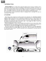
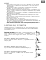
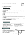
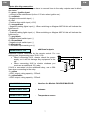
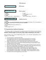
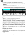
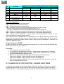
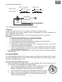
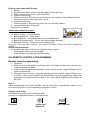
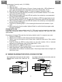
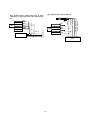
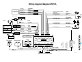
MAGICAR M871A Car alarm with two-way remote Installation guide 1 MAGICAR M871A Car alarm with two-way remote Installation guide 2 TABLE OF CONTENTS I. INTRODUCTION............................................................................................................................4 II. PLACING........................................................................................................................................4 III. ADDITIONAL RELAY 12V CONNECTION..............................................................................5 IV. WIRING ARRANGEMENT ........................................................................................................6 V. Programming of optional functions ............................................................................................8 Programming menu No. 1............................................................................................................9 Programming menu No.2 .............................................................................................................9 VI. CALIBRATION OF THE FUNCTION – HAZARD LIGHT MODE ......................................10 VII. VALET MODE...........................................................................................................................11 Entering valet mode without a pin code...................................................................................11 Entering valet mode with PIN code. .........................................................................................12 Valet mode deactivation.............................................................................................................12 VIII. REMOTE CONTROLS PROGRAMMING...........................................................................12 Remote control programming....................................................................................................12 Security code setup ....................................................................................................................12 Changing PIN code .....................................................................................................................13 IX. WIRING DIAGRAM FOR DOOR LOCKING SYSTEM........................................................13 3 EN I. INTRODUCTION MAGICAR M871A is a safety device with the highest level of security. Thanks to the 2way remote with pager you will be immediately informed about possible car intrusion, as well as the manner of the intrusion even though you are too far from the car to hear the siren. The biggest advance of the two-way remote control is a possibility to use without direct view of the car. All the commands you will send will be confirmed by remote. For even higher security level the car alarm is equipped with a two-digit PIN code for entering the valet mode. II. PLACING When fitting each component consider properly the right place for a microwave interior sensor (if fitted). Since this sensor is working on magnetic principle, it is very sensitive to a magnetic field developed in car solenoid relays, which may cause a false alarm. For example, when checking a car status by the remote controller, parking lights will flash. If the sensor is placed too close to the lights’ relay, it may trigger the alarm. Check this possibility before final fitting of the sensor Place the antenna on front or rear window the way that it is not in your view. As an alternative place you can use the shade on the driver’s side. The antenna is designed for a horizontal use. Any other positioning may cause decrease of operation range Glue the round sticker on the RPS sensor and, after taking the foil off, place the sensor on the front window on a visible place, not in the driver’s view. As a part of the RPS there is a LED diode and a button. The RPS sensitivity level is adjustable on its back side by a three-position switch. 4 EN WARNING! ¾ When installing a door contact, you must find an appropriate wire from the wire bundle of a car (it is important from the security point of view as well as that of remote starting) ¾ Wiring used for the alarm connection must not be broken nor its insulation damaged. This should prevent wiring from short-circuit. ¾ After the installation completed, you have to test the alarm according to the user’s manual. If the alarm works correctly, a car with the installed alarm can be handed over to a customer. ¾ The installation must be carried out in a safe place, in an appropriate distance from busy roads and on a flat surface. ¾ Before the installation get all necessary equipment ready (e.g. servos, diodes, relays, etc.) ¾ When receiving a car from a customer, check functionality of electronics of a car. ¾ Use secure equipment only. ¾ When checking the wires, use a multimeter. ¾ When dealing with cars with airbags, you have to remove the airbag fuse or disconnect a respective connector before the installation. After the installation, put the fuse or the connector back to place. ¾ A key must be removed from the ignition when connecting wires to the switch board. With the key placed in the ignition, an airbag or AMS pilot light could be lit. III. ADDITIONAL RELAY 12V CONNECTION Inappropriate connection of the additional relay may cause various problems when connecting alarm, therefore make sure you read carefully the following examples of connecting the relay 12V. 86 Basic relay description: Contacts 85 and 86 for coil terminals for an electromagnet. If there is no current on this coil, contact 30 is connected to contact 87A. If there is current on this coil, electromagnet attracts terminal 30 to connect it to contact 87. If you want to change the signal polarity from (+) to (-) E.g. the (+) signal of a blinker is changed to a (-) signal and connected to emergency lights. 87 85 87a 30 86 87 85 impuls (+) 87a 30 output (-) +12V 86 87 If you want to change the signal polarity (-) to (+) E.g.: When AUX is installed, a relevant device is operating on (+). 85 impuls (-) If you want to disconnect two wires by a (-) signal E.g.: With a (-) signal, lines A and B are cut off. Use this when a starterblocker is installed. 5 87a 30 output (+) +12V 86 87 85 impuls (-) 87a line A 30 line B +12V 86 If you want to connect shortly two wires by (-) signal. E.g.: Mostly used for installing alarm gas relays. 87 85 impuls (-) line A 87a 30 line B IV. WIRING ARRANGEMENT CONNECTOR 1 – CN1 1 – red - +12V Power supply - power supply, connect to +12V. 2 –red/white – Lights - This is a line for lights output, connect on +12V or earth depending on the type of lights power supply. 3 – purple - Signal lights output. It switches voltage in red/white wire CN1. 4 – purple - Signal lights output. It switches voltage in red/white wire CN1. 5 – white - siren output. When activated provides +12V. 6 – grey - common wire for supply of the trunk opening mechanism. Can be connected to the +12V wire or earth. 7 – grey/white - relay output for trunk opening mechanism (if supplied with a servo or an electromagnet) can be used to open the trunk. It switches voltage in the grey CN1. 8 – black – Chassis Grounding - grounding (-). It must be firmly fixed to the car body. CONNECTOR 2 – CN2 On this connector the complete relay outputs for control of central locking are located. 1 – yellow/black 4 – green/black - door unlocking relay output (NC) - door locking output relay(NC) 2 – yellow 5 – green - common wire (COM) of unlocking relay - common wire (COM) of locking relay 3 – yellow/white 6 – green/white - switch wire (NO) of door unlock relay - switch wire (NO) of door locking relay CONNECTOR 3 – CN3 6 switch board ignition Start line circuit CN3-2 ignition 86 87 CN3-1 Starter-kill Cut off 1 – violet - Wire grounded when alarm on. It controls starter-blocking relay and can also be used for activation of additional modules (interface of el. windows). Rating capacity 250mA. Second relay wire of starter-blocking is connected to ignition. (via the green wire). 85 87a 30 EN EN Starter-blocking connection: After cutting car starter lines, you have to connect lines to the relay outputs used to block the starter. 2 – green - Ignition Input - connect to the switchboard (to the +12V wire when ignition on). 3 – red/black - Negative door switch input ( - ) 4 – red - Positive door switch input (+12V) 5 – orange/black - Negative parking lights input (-). When switching on Magicar M871A this will indicate the lights are on. 6 – orange - Positive parking lights input (+). When switching on Magicar M871A this will indicate the lights are on. 7 – grey/black - Negative hood switch input (-) 8 – brown/black - Negative trunk switch input (-) 9 –black/white - Foot brake input reacting on (+) CONNECTOR 4 - red - additional outputs Additional outputs controlled by the remote control. For settings see programming menu 2-08, 2-09. • When connecting AUX, always check the power supply, so it will not damage any equipment in the car. • When connecting AUX to electric windows you must use an additional 12V relay. If AUX is connected via the additional relay, use a 30A fuse when connecting to the relay. 1 – yellow - AUX1 output, rating capacity - 250mA. 2 – yellow/white - AUX2 output, rating capacity - 250mA. switch Cutt off +12V 86 87 AUX (-) 85 87a 30 CONNECTOR 5 - black - Interface for Module CAN BUS MAGICAR CONNECTOR 6 - blue - Antenna CONNECTOR 7 - blue - Temperature sensor CONNECTOR 8 - white 7 Switching circuit - LED indication CONNECTOR 9 - white - RPS sensor CONNECTOR 10 - red - Shock sensor 1 – black - Grounding 2 – white - Shock sensor input – second level (-) CONNECTOR 11 - green - 3 – red - Power supply of +12 V 4 – yellow - Shock sensor input – first level (-) Additional sensor 1 – black - Grounding – In case of turning the alarm or the additional sensors off, the grounding is disconnected which means the sensor is mains operated. 2 – white - input of additional sensor reacting on (-) 3 – red - Power supply of +12 V V. Programming of optional functions The system allows the programmed activation/settings of the following (mostly system) functions. Because some of them may affect correct functioning of the device, it’s important for these changes to be carried out by professional maintenance service only. Alarm includes a set of two programming menus. You can enter Programming menu number 1 or 2 as follows: 1. Turn the ignition on and open the door. 2. For programming menu No.1 keep buttons l+ll pressed for 2 seconds. For programming menu No.2 keep buttons l+lV pressed for 2 seconds. Siren will beep once to confirm the access of the Programming mode. 3. Within 2 seconds of the step 1 press button IV as many times as is the order number of the function you want to set. After each pressing of button IV the lights will flash and the siren will beep. 4. Wait for a few seconds. Siren will beep and the lights will flash as many times as is the function order number. If the number of flashes is wrong, start the process over. 5. Within 5 seconds after flashing/lightning ends, make your choice: Press button I to choose option 1. Siren beeps once, lights will flash once. Press button II to choose option 2. Siren beeps twice, lights will flash twice. Press button III to choose option 3. Siren beeps 3 times, lights will flash 3 times. Press button IV to choose option 4. Siren beeps 4 times, lights will flash 4 times 6. The alarm will exit the Programming menu mode. 8 EN Note: • If you want to carry out any other changes, start the whole process over again. • If you hear a long beep, you are out of programming menu area. Start again by the step 1. Failure notice: If the remote happened to be out of the range when programming changes, it will display „FAIL“ notice and the programming will be cancelled. Programming menu No. 1 When the door is open and ignition is on keep buttons I and II pressed simultaneously for 2 sec. Options No. Function Button I Button II Button III Button IV 1-10 1-11 1-12 Emergency code RPS Flashing when the doors are open Flashing when the trunk is open PIN code Start kill/IG kill Dome light delay 1-14 CAN mode 1-04 1-06 1-08 Off On - - Off On - - Off On - - Off IG kill Off On Start kill 5 sec 50 sec Read only Read and Write 15 sec Read, Write and close windows - Functions description: 1-04 When on, you can enter a 4-digit emergency code to cancel the alarm and open the car. 1-06 When on, alarm will warn of the door opened by flashing the lights. 1-08 When on, alarm will warn that the hood is open by flashing the lights. 1-10 It allows you to enter the valet mode in two ways: - simple access – by turning ignition on/off 3 times in row - secure access – by turning ignition on/off 3 times in row and entering a 2-digit PIN code by the button on the back side of RPS. 1-11 In case of using the IG kill function, the blocking output is – active (on -250mA) when armed, - inactive during a remote starting and disarmed; in case of using the PANIC function when disarmed, the output will be activated after 30 sec. In case of using the Start kill function, blocking output is – active when armed and remotely started, - inactive when disarmed; in case of using the PANIC function when disarmed, the output will be activated immediately. 1-12 It is possible to set up a delayed reaction to opened door contacts when turning on the alarm. The function is supposed to be used with indirect closed doors scanning (from the roof light, etc.) 1-14 This function is available with CAN BUS Magicar module. In case of using the Read only function, Magicar only read CAN information (open door, trunk, hood, lock/unlock with OEM remote, etc.) In case of using the Read and Write function, Magicar can also control lock/unlock, lights and klaxon except closing windows. In case of using the Read, Write and close windows, Magicar can also close windows when armed.* * See possible function Module CAN BUS Magicar in Table of functions depending on car type. Programming menu No.2 When the doors are opened and ignition is on, keep the buttons I and IV pressed for 2 sec. 9 EN No. Function 2-01 2-02 2-03 2-06 2-08 2-09 Trunk output time Door lock impulse Door unlock impulse Parking lights AUX 1 AUX 2 Shock sensor on/off during AUX output Arm/disarm by OEM remote control 2-11 2-13 Options Button II Button III Button I Button IV 0.5 sec 0.8 sec 0.8 sec Normal mode 0.5 sec 0.5 sec 2 sec 4 sec 4 sec Continuous mode 5 sec 5 sec 3 sec 2 x 0.8 sec 2 x 0.8 sec Pulse mode 40 sec 40 sec 4 sec 15 sec Latch Latch On Off - - Enabled Disabled - - Function explanation: 2-01 Impulse time set-up for trunk output. 2-02 Impulse time set-up for door lock. 2-03 Impulse time set-up for door unlock. 2-06 Using this function, you can set the lights control by the alarm mode. - normal – mainly for direct control of hazard lights by (-) or (+). - 1-2 mode – designed to control hazard lights by the button (see page 36). 2-08 Duration of negative impulse for AUX output No.1 (grounded when activated) 2-09 Duration of negative impulse for AUX output No.2 (grounded when activated) 2-11 It allows you to deactivate a shock sensor by using additional outputs in case connected device is causing sensor reaction. 2-13 When function is disabled then is not possible to arm or disarm alarm by original remote control only by system remote control. When function is enabled alarm will be armed or disarmed by original and system remote control. Alarm must be connected to CAN bus via CAN BUS Magicar module. Programming menu RESET In case you wish to set all the function back to the pre-set, you can do so by the following way. All the functions will be set to option 1. Procedure: 1. Turn the ignition on and open the door. 2. For resetting the programming menu No.1, keep buttons l+ll pressed for 2 seconds. For resetting the programming menu No.2, keep buttons l+lV pressed for 2 seconds. 3. Lights will flash and siren will beep once. 4. Within 2 sec. press the button III. Lights will flash and siren will beep once. Press button III again. Lights will flash and siren will beep once. Press button III again. Lights will flash and siren will beep once. 5. After few seconds siren will beep 3 times and the lights will flash 3 times to confirm the reset of the programming menu. VI. CALIBRATION OF THE FUNCTION – HAZARD LIGHT MODE In case it is not possible to control hazard lights directly for the alarm needs, you can use the hazard light button mode. In this case the alarm, using the lights output, replaces a hazard light switch (Fig.1). In the programming menu 2-06 you can set the continuous mode (Mode1) 10 EN and the pulse mode (Mode 2). Mode 1 – continuous Mode 2 – pulse Output - Lights Lights - flashing Lights Control Unit Hazard Lights Switch Light output (CN1-3 or 4) Common input (CN1-2) Relay contact bypassing the hazard light switch Fig.1 Parking Lights output connected to the Hazard switch Calibration In case of using the mode 1 or 2 it is required to set the time of output closure. In this case alarm will set exact durations, which are necessary for number of flashes used when indicating the alarm status. Before calibration the correct mode (1 or 2) in the Programming menu 2 must be set. Procedure: 1. Switch the hazard light button on – car lights are flashing. 2. Open the door, turn ignition on and press the brake pedal. 3. Long press button III – siren beeps once. 4. Push the button on RPS sensor and hold it at duration of 10 lights flashes. 5. After loosing the button, siren will beep twice. 6. Calibration is successfully completed. Turn the hazard light button off, turn the ignition off and release the brake pedal. 7. Connect the light output wire (CN1-3 or 4) to the hazard light switch wire (Figure No.1). Check the polarity of common wire CN1-2. After this connection the alarm will control flashing of the lights. If the calibration has been done incorrectly, siren will beep 3 times. In this case repeat the whole procedure. VII. VALET MODE You can access the valet mode of the alarm system even without the remote control (in case of a lost or damaged remote). You can enter valet mode without using a PIN code or with a PIN code (Programming menu 1-10). Entering valet mode without a pin code. Armed. Opened doors will trigger the alarm will be triggered. Wait for 30 second until siren is mute. Within 3 seconds repeat the following 3 steps: 1. Turn the key to the “Ignition On” position. When the ignition is on, the lights on the dashboard will be turned on. In most vehicles, this position is located two “clicks” forward from the “Off” position. 2. Turn the ignition off. The lights on the dashboard should be turned off. 3. Steps 1 and 2 must be repeated for a total of three times within three seconds. Once this has been done, the alarm will be turned off and valet mode will be activated. 11 Entering valet mode with PIN code. 1. Armed. 2. By opening the door, the alarm will be triggered. Siren will chirp. 3. Within 3 sec turn the ignition on/off three times. 4. Lights will flash once. 5. Push the button on RPS as many times, as your first number is. Intervals between the click/pushes must not be longer than 1.5 sec. 6. Lights will flash once. 7. Push the button on RPS as many times, as your second number is. 8. Lights will flash twice. Siren is off. Valet mode is activated. Valet mode available functions: Button I (0,5s) – door lock/unlock Buttons I+III (0,5s) – Valet mode Button IV (0,5s) – Car status check (only armed/disarmed) Button III (2x short push) – 10 sec. the remote display backlight. Buttons II + III (2s) – Programming the remote menu. If you try to set any other function, the remote will beep 3 times and will be displaying „SLEEP“. Valet mode deactivation. You can deactivate valet mode only by using the remote control: • Push together shortly buttons I and III. • Siren will beep once and lights will flash twice. VIII. REMOTE CONTROLS PROGRAMMING Remote control programming 1. Disarmed. 2. Within 3 sec turn the ignition on/off three times. The lights will flash once. Now you are in valet/programming mode 3. Within 6 seconds press shortly button l on your remote control. Lights will flash once to confirm programming. 4. The same way as in step 3, program remaining remote controls. Lights will flash once to confirm each remote. System will automatically exit the programming mode after acceptation of the third remote or within 6 sec, which will be signaled by two flashes of the lights. Note !!! When programming new remote controls, the old ones will be automatically erased. If you have only one remote, it is not necessary to program it 3 times. Security code setup Conditions for primary setup of security code! Function in Programming menu 1-04 must be set. Disarmed ignition on / engine off 12 Doors opened EN EN Programming of security code (1111-9999): 1. Ignition on. 2. Open the door. 3. Push the button on RPS sensor 10 times. At every single click, LED will flash red once. Intervals between the click/pushes must not be longer than 1.5 sec. 4. Blue LED will start flashing rapidly. If it does not happen, go back to step 1. 5. Push the button on RPS as many times as your first number between 1-9 is. After each push red LED will flash. 6. After entering the digits, wait until LED will confirm the number by a correspondent number of blue LED flashes. 7. Blue LED will start flashing rapidly. Push the button on RPS as many times as your second number between 1-9 is. At each push of the button red LED will flash once. 8. After entering the digits, wait until LED will confirm the number by a correspondent number of blue LED flashes. 9. Continue by repeating steps 7, 8 for entering the third and fourth number of your code. 10. After entering the fourth number, lights will flash to confirm that the program code has been accepted. Changing PIN code PIN code is set as the factory default code (11). PIN code must be inserted to enter Valet mode after turning key on/off 3 times if you have already selected “PIN code ON” from optional table. Procedures of change PIN code from the factory default code 11 to owner’s own code 1. System is disarmed. 2. Maintain the conditions of the trunk and the door being opened. 3. Within 3 sec turn the ignition on/off three times. Lights will flash once. Siren makes a long beep. 4. Push the button on RPS as many times, as your first number (1-9) is. Intervals between the click/pushes must not be longer than 1.5 sec. 5. Siren beeps once. Lights will flash once. 6. Push the button on RPS as many times, as your second number (1-9) is. 7. Siren beeps twice. Lights will flash twice. 8. Press button IV on remote for authentication. Siren beeps three times and lights will flash three times. IX. WIRING DIAGRAM FOR DOOR LOCKING SYSTEM Fig.1 Original built-in central power lock with a switch inside the doors. A motor at the control level are required. yellow/black yellow yellow/white CN2 green/black green NC1 CN2 yellow/black yellow yellow/white green/black green green/white NC1 COM1 NO1 NC2 COM2 green/white NO2 COM1 NO1 NC2 COM2 NO2 Unlock Lock Unlock +12V Fig.2 Original central power lock & electric power lock switch inside the front doors.. +12V Lock Front door switch 13 Fig.4 Original built-in central power lock Fig.3 Original built-in central power lock & using compressor to control the switch. Note: Active time 4 sec. CN2 Unlock Lock green/black green green/white Air-compressor Main line Electric motor switch yellow yellow/white NC1 COM1 NO1 NC2 COM2 NO2 Contact - locked yellow/black Contact - unlocked NO1 NC2 COM2 NO2 Locked COM1 Unlocked NC1 Ground CN2 yellow/black yellow yellow/white green/black green green/white Original built-in control unit. 14 EN Wiring diagram Magicar M871A Lock (NO) Lock (COM) Lock(NC) Unlock (NO) Unlock (COM) Unlock (NC) Wiring diagram door lock system Page 39 6 green/white 5 green 4 green/black 3 yellow/white 2 yellow 1 yellow/black fuse 15A fuse 15A Output to Starter kill (-250mA) Ignition input Door trigger input (-) Door trigger input (+) 1 violet 2 green 3 red/black 4 red Parking light input (-) Parking light input (+) 5 orange/black 6 orange Trunk trigger input (-) Hood trigger input (-) 7 gray/black 8 brown/black Foot brake input (+) 9 black/white +12V Trunk selenoid Trunk wire - Siren When Signal Light wire is connect to + + Common wire + - Ground 8 black Trunk (NO) 7 gray/white Trunk (COM) Output to siren 6 gray 5 white Light (NO) Light (NO) 4 purple 3 purple Light (COM) 12V constant 2 red/white 1 red - then Common wire - + fuse 10A CN 1 + fuse 15A fuse 5A CN 2 +12V CN 3 Optional | red + | white input | black - | Battery Additional/Ultrasonic sensor RPS sensor MAGICAR CN 6 CN 7 CN 8 CN 9 2 LED signaling Temperature sensor MAGICAR CN 4 2 yellow/white 1 yellow CN 11 CN 10 Antenna Shock sensor AUX 1 (-250mA) AUX 2 (-250mA) CN 5 CAN BUS MAGICAR Module Ver. 1.00 - The car alarm system is designed for fitting into all kinds of cars with petrol and diesel engines with +12V volatge finished by a negative pole. Car alarm must be fitted following manufacturer‘s recommendation. The alarm installation to be carried out only by authorised service centre. Consult the choice of the service sentre with a manufacturer. International approval marks and/or international certificates of conformity are attached onto the cover of system main parts as well as onto the box. Warning: Any alternations or additions to the system will automatically invalidate the installation certificate. INSTALLATION CERTIFICATE I, the undersigned, as a professional installer, hereby certify that the installation of the vehicle alarm system described below has been carried out by myself pursuant to the mounting instructions supplied by the manufacturer of the system. Description of the vehicle: Make: Type: Serial number: Registration number: Description of the vehicle alarm system/immobilizer 1/: Make: Type: Approval number: Issued by: Installer's full address and stamp: Signature: (please specify position) 1/ Cross out if does not apply. 16