1
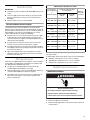
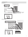
VARIABLE SPEED ELECTRIC FURNACE
INSTALLATION INSTRUCTIONS
Table of Contents
VARIABLE SPEED ELECTRIC FURNACE SAFETY.....................1
INSTALLATION REQUIREMENTS ................................................2
Tools and Parts ............................................................................2
Location Requirements................................................................2
Installation Configurations ...........................................................3
Electrical Requirements ...............................................................4
Duct Work Requirements.............................................................4
INSTALLATION INSTRUCTIONS ..................................................4
Inspect Shipment .........................................................................4
Install Duct Work ..........................................................................5
Filter Specifications ......................................................................5
Make Electrical Connections .......................................................5
Complete Installation..................................................................10
SEQUENCE OF OPERATION ......................................................12
ELECTRIC FURNACE MAINTENANCE ......................................13
ASSISTANCE OR SERVICE .........................................................13
Accessories ................................................................................13
WARRANTY ..................................................................................14
VARIABLE SPEED ELECTRIC FURNACE SAFETY
Your safety and the safety of others are very important.
We have provided many important safety messages in this manual and on your appliance. Always read and obey all
safety messages.
This is the safety alert symbol.
This symbol alerts you to potential hazards that can kill or hurt you and others.
All safety messages will follow the safety alert symbol and either the word “DANGER” or
“WARNING.” These words mean:
You can be killed or seriously injured if you don't
immediately follow instructions.
You can be killed or seriously injured if you don't
follow instructions.
All safety messages will tell you what the potential hazard is, tell you how to reduce the chance of injury, and tell you
what can happen if the instructions are not followed.
065682600
INSTALLATION
REQUIREMENTS
These instructions are intended to be a general guide and do not
supersede any local or national codes. Installation must conform
with the local building codes and with the latest editions of the
National Electric Code.
Read the entire instruction manual before starting the installation.
All models are designed for indoor installations only.
The unit is shipped from the factory completely assembled to be
configured for upflow, counterflow, right to left or left to right air
flow depending on the installation.
Do not remove the cabinet knockouts until it has been
determined which knockouts will need to be removed for the
installation.
The electric furnace may be used with an optional modular
evaporator coil (WME) in upflow, counterflow, or horizontal
applications. See “Airflow Configuration Options” for acceptable
system configurations. The mounting plates and the necessary
hardware to connect the electric furnace and modular evaporator
coil cabinets together are included with this product.
An optional electric heater may be installed in this cabinet.
Select the final installation position which best suits the site
conditions. Select any accessories that are to be included in the
installation. Consider required clearances for the accessories to
be used and the access space, filters, duct work, wiring, and
service accessibility. For the electric heater accessory, refer to
the electric heater rating plate for specific information regarding
electrical supply.
Tools and Parts
Assemble the required tools and parts before starting installation.
Read and follow the instructions provided with any tools listed
here.
Tools Needed:
■
¹⁄₄ in. Nut driver
■
Adjustable wrench
■
Level
■
Tape measure
■
Screwdriver
Parts Needed:
Check local codes and HVAC supplier. Check existing electrical
supply, and read “Electrical Requirements,” “Location
Requirements,” and “Install Duct Work.”
■ UL listed wire nuts
Location Requirements
Explosion Hazard
Keep flammable materials and vapors, such as
gasoline, away from electric furnace.
Place electric furnace so that heating elements are at
least 18 inches (46 cm) above the floor for a garage
installation.
Failure to follow these instructions can result in death,
explosion, or fire.
2
Installation Configuration Options
Installation Configurations
For ease in installation, it is best to make any necessary coil
configuration changes before setting the electric furnace in place.
See “Installation Configuration Options.”
NOTE: Typical installations with optional WME modular
evaporator coil are shown.
Counterflow
Vertical Installations
Upflow/Counterflow
The electric furnace must be supported on the bottom only and
set on solid floor or field supplied supporting frame. Securely
attach the electric furnace to the floor or supporting frame.
Horizontal Installations
Horizontal installations can be left-hand or right-hand air supply.
The cabinet must be supported by the building structure to
ensure cabinet integrity. Ensure that there is adequate room to
remove the blower access panel if installing in the horizontal
position.
Suspended Cabinet Installation
NOTE: Electric furnaces cannot be installed in such a way that
the blower access panel is facing up or down.
■ The suspending means must be field fabricated, and should
consist of two “cradles” made by attaching two rods to a
length of angle iron or suitable gauge steel.
■
Locate the cradles so that they are as close as possible to the
ends of the electric furnace (this will provide access for
removal of major components such as the blower assembly).
■
Provide enough clearance between the suspension rods and
the electric furnace to allow removal of the blower access
panel.
Upflow
Left to Right
Airflow
Right to Left
Airflow
Horizontal
3
Electrical Requirements
WARNING
Duct Work Requirements
■
Install the conditioned air plenum, ducts and air filters (not
provided) in accordance with NFPA 90B Standard for the
Installation of Warm Air Heating and Air-Conditioning
Systems (latest edition).
■
The electric furnace is provided with flanges for the
connection of the plenum and ducts.
■
Air filters must be listed as Class 2 furnace air filters.
■
Supply and return duct work must be adequately sized to
meet the system’s air requirements and static pressure
capabilities. Duct work should be insulated with a minimum
of 1 in. thick insulation with a vapor barrier in conditioned
areas or 2 in. minimum in unconditioned areas.
■
Supply plenum should be the same size as the flanged
opening provided around the blower outlet and should
extend ideally at least 3 ft from the electric furnace before
turning or branching off plenum into duct runs.The plenum
forms an extension of the blower housing and minimizes air
expansion losses from the blower.
Electrical Shock Hazard
Electrically ground furnace.
Connect ground wire to green pigtail lead.
Failure to do so can result in death or electrical shock.
NOTE: Use copper conductors only.
■ All field wiring must be done in accordance with National
Electrical Code, applicable requirements of UL and local
codes.
■
Electrical wiring, disconnect means and overcurrent
protection are to be supplied by the installer. Refer to the
electric furnace rating plate for maximum overcurrent
protection, minimum circuit ampacity, as well as operating
voltage.
■
The power supply must be sized and protected according to
the specifications supplied on the product.
■
This electric furnace is factory configured for 240 Volt, single
phase, 60 cycles. For 208 Volt applications, see “208 Volt
Conversion” in the “Make Electrical Connections” section.
■
For optional electric heater applications, see “Accessories.”
Refer to the instructions provided with the accessory for
proper installation.
INSTALLATION
INSTRUCTIONS
Inspect Shipment
WARNING
Excessive Weight Hazard
Use two or more people to move and install furnace.
Failure to do so can result in back or other injury.
The electric furnace is completely factory assembled, and all
components are performance tested. Each unit consists of a
blower assembly and controls in an insulated, galvanized factory
finished enclosure. Knockouts are provided for electrical wiring
entrance.
1. Check the unit rating plate to confirm specifications are as
ordered.
2. Upon receipt of equipment, carefully inspect it for possible
shipping damage. Take special care to examine the unit
inside the carton if the carton is damaged.
If damage is found, it should be noted on the carrier’s freight bill.
Damage claims should be filed with the carrier immediately.
Claims of shortages should be filed with the seller within 5 days.
NOTE: If any damages are discovered and reported to the carrier,
do not install the unit as your claim may be denied.
4
Minimum Filter Requirements Chart
Install Duct Work
Nominal Tons
Air Conditioning
&
Nominal Airflow
IMPORTANT:
■ Install duct work in accordance with NFPA 90B and any local
codes.
■
■
Connect supply air duct to the flange on top of the electric
furnace. If an isolation connector is used, it must be nonflammable.
If the free area is not known, assume a 25% free area for
wood or a 75% free area for metal louvers or grilles.
■
If the return air plenum is used, the return air grille should be
immediately in front of the opening in the plenum to allow for
the free flow of return air.
■
When not installed in front of the opening, there must be
adequate clearance around the electric furnace to allow for
the free flow of return air.
Filter Specifications
Filters are not supplied with these air handlers. It is the installer's
responsibility to install properly sized filters in accordance with
the “Minimum Filter Requirements Chart.”
■ The filter size is determined by the “Nominal Tons Air
Conditioning & Nominal Airflow” (see chart).
■
Areas and dimensions shown for cleanable filters are based
on filters rated at 600 ft per minute face velocity.
■
Typical filter sizes are shown; however, any combination of
filters whose area equals or exceeds the minimum area
shown is satisfactory.
Cleanable
Filters
432 sq. in.
20 in. x 25 in.
260 sq. in.
15 in. x 20 in.
260 sq. in.
2¹⁄₂ Tons
900-1000 CFM
480 sq. in.
20 in. x 30 in.
288 sq. in.
14 in. x 25 in.
288 sq. in.
3 Tons
576 sq. in.
346 sq. in.
1300 - 1500 CFM *14 in. x 25 in. 16 in. x 25 in.
346 sq. in
3¹⁄₂ Tons
672 sq. in.
404 sq. in.
1300 - 1500 CFM *16 in. x 25 in. 20 in. x 25 in.
404 sq. in.
4 Tons
768 sq. in.
461 sq. in.
1500 - 1700 CFM *20 in. x 25 in. 20 in. x 25 in.
461 sq. in.
5 Tons
960 sq. in.
576 sq. in.
1900 - 2100 CFM *20 in. x 30 in. 24 in. x 25 in.
576 sq. in.
Non-Ducted Return Closet Installation
■
Disposable
Filters
Minimum
Return Air
Free Area
Up to 2 Tons
800 - 900 CFM
A return air duct system is recommended.
The electric furnace can be installed in a closet with a false
bottom to form a return air plenum or be installed with a return air
plenum under the electric furnace. Louvers or return air grilles are
field supplied. Local codes may limit application of systems
without a ducted return to single-story buildings.
■ Install louvers in a closet. Use the free area of louver or grille
to determine the size opening required to provide the free
area for metal louvers or grilles. See “Filter Requirements” for
minimum free area required.
Square Inch Surface Area
& Nominal Size
* 2 disposable filters required for these units
If a central return air filter-grille is used, the electric furnace does
not require a filter.
To install a filter at the electric furnace only, use the following kits:
■
AEFFLTS-1 Filter Kit for 17.5 in. x 22.5 in. cabinets
■
AEFFLTM492-1 Filter Kit for 22 in. x 21.5 in. cabinets
■
AEFFLTL493-1 Filter Kit for 22 in. x 26 in. cabinets
Make Electrical Connections
208/240 Volt Installations
WARNING
Electrical Shock Hazard
Disconnect all power supplies before servicing.
Replace all parts and panels before operating.
Failure to do so can result in death or electrical shock.
1. Disconnect all power supplies.
2. Remove the blower access panel.
3. Route the field supply wires to the electric furnace electrical
connection box.
5
4. Using UL listed wire nuts, connect the field supply wires to
the electric furnace (black to black and yellow to yellow).
208 Volt Conversion
WARNING
Electrical Shock Hazard
Disconnect all power supplies before servicing.
WARNING
Replace all parts and panels before operating.
Failure to do so can result in death or electrical shock.
1. Disconnect all power supplies.
2. Remove the blower access panel.
3. Move the 2 connected black transformer leads from the 240
Volt terminal on the transformer to the 208 Volt terminal on
the transformer. See “Wiring Diagram - Blower”.
Electrical Shock Hazard
Electrically ground furnace.
Connect ground wire to green pigtail lead.
Failure to do so can result in death or electrical shock.
5. Connect ground wire to green pigtail lead.
1
2
3
1. Connect black to black
2. Connect yellow to yellow
3. Connect green to green
6. Replace the blower access panel.
6
Low Voltage Connections
Cooling Application
WEFV Electric Furnace
R
Y
W
G
GRN
WHT
BLK
RED
ORG
YEL
BLU
To Compressor
Contactor
Make this connection only if electric heat is used.
Connections for Staged Electric Heat
W2
W1
BLK
WHT
Heat Pump Application
WEFV Electric Furnace
L
E
W
G
C
O
Y
R
1
RED
YEL
ORG
GRN
BLU
WHT
1
BLK
Common used on some thermostats
Connections for Staged Electric Heat
W1
W2
BLK
R
Y
O
C
W
Outdoor Heat Pump
WHT
7
Electric Heat Only
R
W
WEFV Electric Furnace
G
GRN
WHT
BLK
RED
ORG
Connections for Staged Electric Heat
W1
W2
BLK
WHT
Blower Only
R
WEFV Electric Furnace
G
GRN
RED
ORG
8
Wiring Diagram - Blower
COM
8
18 BLK
7
18 BRN
6
18 WHT
5
18 GRN
18 RED
GND
12-PIN PLUG
2
18 BLU
4
3
14 YEL L2
14 BLK L1
1
CONTROL BOARD
24V
HUM
R
C1
EM
W1
O
Y2
Y1
G
18 BLU
208V
18 RED
240V
TRANS
24V
18 RED
18 BLUE
18 BLK
18 WHT
18 ORG
TO THERMOSTAT
18 YEL
18 GRN
16-PIN PLUG & CAP
18 BRN (16)
16-PIN PLUG & CAP
18 BLK
18 YEL
18 GRN
GND
LINE VOLTAGE
LINE VOLTAGE
LOW VOLTAGE
LOW VOLTAGE
5
4
3
MOTOR
5-PIN 5-PIN
PLUG CAP
FACTORY
FIELD
FACTORY
FIELD
9
■
Is unit properly located, level, secure, and serviceable?
■
Is the wiring neat, correct, and to the wiring diagram?
■
Is the unit properly grounded and protected (fused)?
■
Is the thermostat correctly wired, level, and in a good
location?
3. Set the HEAT and COOL taps by moving the board jumpers
to the A, B, C, or D positions (see Motor Board Taps and
Dehumidify Resistor) based on the information found in the
Application Table.
NOTE: If using a humidistat, the dehumidify resistor located
on the bottom right of the control board must be removed to
enable it. See Control Board Taps and Dehumidify Resistor.
The HUM terminal on the board must be connected to the
Normally Closed contact of the humidistat so that the board
senses an open circuit on high humidity. If a humidistat is
used, the dehumidify LED (see D1 below) will light when the
humidistat opens and the motor runs at reduced airflow.
■
Are all access panels in place and secure?
Control Board Taps and Dehumidify Resistor.
Complete Installation
Pre-Start Check
Check Airflow
ADJUST
The Control Board
The control board regulates airflow selection and features LED
indicators that display operating mode, humidity control, and
airflow CFM. The red LED flashes once for each 100 CFM. For
example, if the operating CFM is 1200, the CFM LED will flash 12
times, then pause before repeating the 12-flash pattern.
Thermostat signals for emergency heat (EM), auxiliary heat (W1),
reversing valve (O), compressor (Y1), and blower (G) are all
indicated by lit LED’s on this board.
This model is designed for use with heat pumps as well as air
conditioning systems. The control board needs to sense a signal
on the “O” thermostat wire in order to use cooling delay timing.
For a straight air conditioning system, connect the “O” wire to the
24 volt “R” wire.
WARNING
NORM
(+)
(–)
TEST
1
HEAT
COOL
A
B
C
D
A
B
C
D
D1
DEHUMIDIFY
2
CUT TO ENABLE
1. Dehumidify LED
2. Dehumidify resistor
4. If desired, adjust ADJUST tap from NORM: (+) will increase
airflow by 10% or (-) will decrease airflow by 12%
5. Reconnect all power supplies.
Application Table
Electrical Shock Hazard
Disconnect all power supplies before servicing.
Replace all parts and panels before operating.
Failure to do so can result in death or electrical shock.
1. Disconnect all power supplies.
2. Locate the control board in the blower control box.
10
The versatility of the variable speed motor enables the electric
furnace to tailor its performance to the different modes of
operation encountered in heating and cooling. All variable speed
electric furnaces are capable of operation at more than one
nominal airflow rate.The operation of a variable speed electric
furnace blower at different airflow rates is determined by the
control board taps and the thermostat. See the Application Table.
Before beginning the setup, become familiar with the information
found in the Application Table. The data in the application table is
categorized by model size and mode of operation. Use the
information provided to determine the CFM taps needed for
cooling and heating.
Application Table
Control Board Taps
Thermostat Terminals
X = Energized Terminal
Model
Mode
A
HUM
EM
W1
O
Y2/Y1
Cont. Blower
Cooling
WEFV08S -1A
**
X
Heating
X
Emer. Heat***
X
Aux. Heat***
X
Emer. Heat***
X
1000 800
700
600
X
1000 800
700
600
WEFV14M-1A
Aux. Heat***
X
Emer. Heat***
X
800
700
600*
***
***
***
***
1000
800
700
600*
600
500
400
350
X
1200 1000 800
600
X
1200 1000 800
600
WEFV16M-1A
Aux. Heat***
X
Emer. Heat***
X
WEFV20L-1A
Aux. Heat***
Emer. Heat***
X
X
X
***
***
***
1200 1100* 1100* 1100*
750
700
600
500
***
***
***
***
1500 1400 1200* 1200*
***
***
***
***
1500 1400 1200* 1200*
900
800
750
700
X
1800 1600 1500 1400
X
Heating
***
1800 1600 1500 1400
X
X
1200 1100* 1100* 1100*
X
X
**
***
1500 1400 1200 1000
Cont. Blower
Cooling
***
X
X
Heating
***
1500 1400 1200 1000
X
X
***
X
X
**
CFM
1000
Cont. Blower
Cooling
CFM
***
X
Heating
D
***
X
X
500
C
***
X
**
B
***
Cont. Blower
Cooling
A
CFM CFM CFM CFM CFM CFM
X
X
Heating
D
375
X
X
C
375
X
**
B
Heat
400
Cont. Blower
Cooling
G
X
Aux. Heat***
WEFV12S-1A
Cool
***
***
***
***
1800 1700 1600* 1500*
***
***
***
***
1800 1700 1600* 1500*
900
800
1000 950
X
2000 1900 1800 1600
X
2000 1900 1800 1600
X
***
***
***
***
2000 1800
1700
1700
***
***
***
***
2000 1800
1700
1700
*This CFM is not approved for use with highest kW heater size.
**Humidistat will reduce cooling airflow by 10% in high humidity.
***Airflow is the greater of the COOL and HEAT values when both electric heat and heat pump are operating.
NOTES:
Adjust tap (+) will increase airflow by 10%, while tap (-) will decrease airflow by 12%.
Adjust tap test will cause the motor to run at 70% of full airflow. Use this for troubleshooting only.
At the start of a call for cooling there is a short run at 82% of airflow for 7.5 minutes.
At the end of a call for cooling there is a blower delay of 1 minute.
11
SEQUENCE OF OPERATION
Cooling (cooling only or heat pump)
When the thermostat calls for cooling, the circuit between R and
G is completed, and the blower relay is energized. The Normally
Open contacts close, causing the indoor blower motor to
operate. The circuit between R and Y is also completed; this
circuit closes the contactor in the outdoor unit starting the
compressor and outdoor fan motor. Circuit R and O energizes the
reversing valve, switching it to the cooling position. (The
reversing valve remains energized as long as selector switch is in
the COOL position.)
Heating (electric heat only)
When the thermostat calls for heat, the circuit between R and W
is completed, and the heater sequencer is energized. A time
delay follows before the heating elements and the indoor blower
motor come on. Units with a second heat sequencer can be
connected with the first sequencer to W on the thermostat subbase or connected to a second stage on the sub-base.
Heating (heat pump)
When the thermostat calls for heat, the circuits between R and Y
and R and G are completed. Circuit R-Y energizes the contactor
starting the outdoor fan motor and the compressor. Circuit R and
G energizes the blower relay starting the indoor blower motor.
If the room temperature should continue to fall, the circuit
between R and W 1 is completed by the second stage heat room
thermostat. Circuit R-W 1 energizes a heat sequencer. The
completed circuit will energize supplemental electric heat (if
applicable). Units with a second heater sequencer can be
connected with the first sequencer to W 1 on the thermostat or
connected to a second heating stage W 2 on the thermostat subbase.
Auxiliary Heat (heat pump)
When the thermostat functions to call for auxiliary heat, the heat
pump is turned off. Place a jumper wire between Terminals W2
and E on the thermostat terminal connections. See Heat Pump
Application wiring diagram. This will allow the indoor blower to
cycle on and off with the electric heat when the fan switch is in
the AUTO position.
12
Variable Speed Features
The EFV electric furnace is equipped with a variable speed motor
and will deliver a constant airflow within a wide range of external
static pressures. The variable speed blower offers the following
comfort features:
Soft Start
When called into operation, the variable speed motor will slowly
ramp up to normal operating speed. This eliminates the noise
and discomfort that results caused by the initial blast of air
encountered with standard electric furnaces. It can take up to 7.5
minutes to reach normal operating speed.
Continuous Blower Operation
The comfort level of the living space can be enhanced when
using this feature by allowing continuous circulation of air in
between calls for cooling or heating. The circulation of air
between calls for cooling or heating occurs at 50% of the normal
airflow rate (350 CFM minimum).
Reduced Airflow Operation
For situations where humidity control is a problem, the variable
speed motor can be enabled to operate at a 10% reduction in the
normal airflow rate under the control of a humidistat. This can be
achieved by connecting to a standard humidity control that is
normally closed and opens on humidity rise.
ELECTRIC FURNACE
MAINTENANCE
IMPORTANT: Do not operate system without a filter. A filter is
required to protect the coil, blower, and internal parts from
excessive dirt and dust.
■ Inspect air filters at least once a month and replace or clean
as required. Dirty filters are the most common cause of
inadequate heating or cooling performance.
■
Replace disposable filters. Cleanable filters can be cleaned
by soaking in mild detergent and rinsing with cold water.
■
Install new/clean filters with the arrows on the side pointing in
the direction of airflow.
■
Never replace a cleanable (high velocity) filter with a
disposable (low velocity) filter unless return air system is
properly sized for it.
ASSISTANCE OR SERVICE
If you need further assistance, you can write to the below
address with any questions or concerns:
Whirlpool® Home Cooling and Heating
7901 S.W. 6th Court
Plantation, Florida 33324
Please include a daytime phone number in your correspondence.
Accessories
To order accessories ask for the appropriate part number listed
below or contact your Whirlpool® Home Cooling and Heating
dealer.
AEFFLTS-1
AEFFLTM492-1
AEFFLTL493-1
Filter Kit for 17.5 in. x 22.5 in. cabinets
Filter Kit for 22 in. x 21.5 in. cabinets
Filter Kit for 22 in. x 26 in. cabinets
Electric Heat Kits
Refer to the Accessory Kit Label on the front panel of the electric
furnace for electric heat kit options and applications.
13
14
Keep this book and your sales slip together for future
reference. You must provide proof of purchase or installation
date for in-warranty service.
Write down the following information about your furnace to better
help you obtain assistance or service if you ever need it. You will
need to know the complete model and serial number. You can
find this information on the front panel.
Dealer name____________________________________________________
Address ________________________________________________________
Phone number __________________________________________________
Model number __________________________________________________
Serial number __________________________________________________
Installation date ________________________________________________
15
065682600
© 2003. All rights reserved.
®/TM Whirlpool and all other trademarks are owned by Whirlpool, U.S.A.,
used under license by Tradewinds Distributing Company, LLC.
7/03
Printed in U.S.A.