1
VLT 5000/5000 FLUX SyncPos Quick-Setup
■ Safety ...................................................................... 2
Chapter 2
■ Introduction ........................................................... 3
Chapter 3
■ Typical application example .................................. 4
Chapter 4
■ Basic SyncPos information .................................. 6
Chapter 5
■ Installing the SyncPos PC Software ................... 8
Chapter 6
■ Checking encoder connections ........................... 9
Chapter 7
■ Commissioning Guide ........................................ 11
Chapter 8
■ 10 steps to optimise the PID loop .................... 11
Chapter 9
■ Error and Messages ............................................ 17
Chapter 10
■ Technical data/wiring examples ........................ 25
MG.10.Q1.5B – VLT is a registered Danfoss trade mark
1
Contents
Chapter 1
Safety
VLT 5000/5000 FLUX SyncPos Quick-Setup
■
The voltage of the frequency converter
is dangerous whenever the equipment
is connected to mains. Incorrect
installation of the motor or the frequency converter
may cause damage to the equipment, serious
personal injury or death.
Consequently, the instructions in this manual,
as well as national and local rules and safety
regulations, must be complied with.
■ Safety regulations
1. The VLT frequency converter must be disconnected from mains if repair work is to be carried
out.
Check that the mains supply has been disconnected and that the necessary time has passed
before removing motor and mains plugs.
2. The [STOP/RESET] key on the control panel of
the VLT frequency converter does not disconnect the equipment from mains and is thus not
to be used as a safety switch.
3. Correct protective earthing of the equipment
must be established, the user must be protected against supply voltage, and the motor must
be protected against overload in accordance
with applicable national and local regulations.
4. The earth leakage currents are higher than
3.5 mA.
5. Protection against motor overload is not included in the factory setting. If this function is
desired, set parameter 128 to data value ETR
trip or data value ETR warning.
Note: The function is initialised at 1.16 x rated
motor current and rated motor frequency (see
page 92).
For the North American market: The ETR functions provide class 20 motor overload protection
in accordance with NEC.
6. Do not remove the plugs for the motor and
mains supply while the VLT frequency converter
is connected to mains. Check that the mains
supply has been disconnected and that the
necessary time has passed before removing
motor and mains plugs.
7. Please note that the VLT frequency converter
has more voltage inputs than L1, L2 and L3,
when loadsharing (linking of DC intermediate
circuit) and external 24 V DC have been
installed.
Check that all voltage inputs have been disconnected and that the necessary time has passed
before repair work is commenced.
■ Warning against unintended start
1. The motor can be brought to a stop by means
of digital commands, bus commands, references or a local stop, while the frequency converter is connected to mains.
If personal safety considerations make it
necessary to ensure that no unintended start
occurs, these stop functions are not sufficient.
2. While parameters are being changed, the motor
may start. Consequently, the stop key [STOP/
RESET] must always be activated, following
which data can be modified.
3. A motor that has been stopped may start if
faults occur in the electronics of the VLT
frequency converter, or if a temporary overload
or a fault in the supply mains or the motor
connection ceases.
Warning:
Touching the electrical parts may be fatal - even after the equipment has been
disconnected from mains.
Also make sure that other voltage inputs have been disconnected, such as
external 24 V DC, load-sharing (linkage of DC intermediate circuit), as well as
the motor connection for kinetic back-up.
Using VLT 5001-5006 220 and 500 V units: wait at least 4 minutes
Using VLT 5008-5500 220 and 500 V units: wait at least 15 minutes
Using VLT 5001-5005 550-600 V units: wait at least 4 minutes
Using VLT 5006-5022 550-600 V units: wait at least 15 minutes
Using VLT 5027-5250 550-600 V units: wait at least 30 minutes
2
MG.10.Q1.5B – VLT is a registered Danfoss trade mark
VLT 5000/5000 FLUX SyncPos Quick-Setup
Introduction
■ About this manual: How is it arranged?
Please read these operating instructions in full and,
in order to be able to work with the system safely
and professionally, particularly observe the hints and
cautionary remarks. It is important to have
knowledge about operating a VLT 5000/5000 FLUX.
Indicates a general warning
Indicates something to be noted by the
reader
Indicates a high-voltage warning
MG.10.Q1.5B – VLT is a registered Danfoss trade mark
3
Typical application example
VLT 5000/5000 FLUX SyncPos Quick-Setup
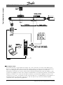
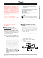
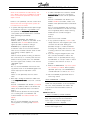
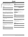
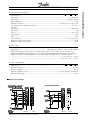
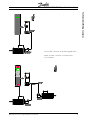
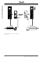
■ Description in brief
The tire will enter the conveyor belt from the right. This, in turn, will start to run at the same speed as the
previous conveyor belt. When the tire reaches the centering station it will stop. The tire will be centered and
stays in the waiting position until the machine has finished measuring the "previous" tire. When the
measurement is finished, the conveyor and the new tire will be positioned exactly under the spindle. In order
to prevent any slippage of the tire, the acceleration and deceleration of the positioning will be controlled by the
frequency converter in such a way that we obtain the fastest cycle time without slippage of the tire on the
conveyor. A PC is shown connnected to the VLT via RS 485 but this is not needed during normal operation as
the APOS program can be stored in the SyncPos card. This picture only shows the minimum required
components for a simple positioning application.
4
MG.10.Q1.5B – VLT is a registered Danfoss trade mark
VLT 5000/5000 FLUX SyncPos Quick-Setup
Typical application example
MG.10.Q1.5B – VLT is a registered Danfoss trade mark
5
Basic SyncPos information
VLT 5000/5000 FLUX SyncPos Quick-Setup
■ How SyncPos functions
Let us explain the basic principle of SyncPos in brief:
Determining parameters
Factory settings are stored in the program for all
parameters. These factory settings are active upon
delivery.
You can adjust all the parameters for your controller.
These user parameters are permanently saved in
the EEPROM and are valid for all programs.
Before you start programming it is necessary to
determine basic parameters of the VLT connected,
such as Maximum velocity VELMAX (1) and
Shortest ramp RAMPMIN (31), set the PID filter
values and define the User factor with POSFACT_Z
(23) and POSFACT_N (26).
Within a program you can temporarily alter the
parameters with the command SET. After running
the program these values are once again replaced
with the user parameters which have been saved.
Programming with the SyncPos macro-language
In the "EDIT" menu you can create and comment
on the programs just like in a text program.
Each command consists of a COMMAND WORD +
parameter (if necessary), whereas the parameter
can be a variable, constant or an array.
Comments are written between /* … */ or after //
for example:
POSA 3000
/* axis absolute to actual zero point move to
position 3000 */
// axis absolute to actual zero point move to
position 3000
It is particularly easy to write your program by
using the "COMMAND LIST". Once you have selected the command, all the necessary input fields
are immediately opened. After entering the values
the syntax is automatically formed and you can
insert the entire command in your program.
With teach-in programming you simply move the
axis to the desired position and store the position
which has been reached. In this manner you can
quickly program the most complicated adjustments and sequences of movements.
6
Running and testing programs
In the "DEVELOPMENT" menu you can test new
programs. The program is loaded into the VLT and
started only after the "EXECUTE" function has been
activated. Naturally, you can run the program being
tested in "SINGLE STEPS" or start the program at a
certain point and have it executed step-by-step.
Before every run a new program is automatically
checked to ensure that the commands are correct.
Or you can start the "SYNTAX CHECK" without
running the program.
Saving programs in the VLT
Every time you Execute a program or start the
syntax check, this program is temporarily stored in
the RAM in an area that is always overwritten with
every subsequent test.
Once you have finished writing a program for the
SyncPos option, the temporary program can be saved
permanently in EEPROM. It will then be assigned a
number or name and can be tagged with "AUTOSTART"
so it automatically will be started after turning on the VLT.
This way you can drive the VLT offline.
All programs can also be started using the program
number via the inputs, for example from a PLC. For
this the inputs must be set accordingly with
"CONTROLLER" → "PARAMETERS" → "GLOBAL".
Optimizing the controller with the control
parameters
The position control unit integrated in the SyncPos
motion controller automatically calculates a theoretical set course during each sequence of movements. The PID loop then controls the VLT to
minimize the deviation from the set course. By
means of the control parameters you can directly
influence to what degree and how quickly a
deviation from the theoretical set course is
corrected.
The experimental method with the functions in the
"TESTRUN" menu can be used to optimize the PID
loop.
After every "TESTRUN" it is also possible to evaluate
the control parameters on the basis of four graphics:
they show the actual and set curves for the velocity,
the acceleration, the position and the power curve.
Thus, you can successively adjust the PID filter
parameters and optimize the controller.
MG.10.Q1.5B – VLT is a registered Danfoss trade mark
VLT 5000/5000 FLUX SyncPos Quick-Setup
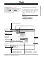
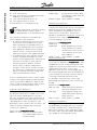
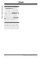
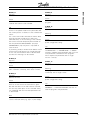
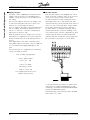
■ The SyncPos Window
The following figure serves to explain the most
important elements of the SyncPos Windows.
Each window represents a SyncPos program which
can be connected with a VLT. Thus, you can open
at least the same number of edit windows as the
number of controllers resp. VLTs you have
selected.
Symbol bar
Click on the icons in the symbol bar to quickly
select a function.
From left to right: New file, Open file, Save file, Cut,
Copy, Paste, Info and CAM-Editor.
Title bar shows the names of the SyncPos File, the number and name of the VLT
and the error number if applicable.
Open the menus in the Menu bar to select the SyncPos functions.
Menus with the functions which you can mark and select with
the mouse.
Click on the icon in
the Symbol bar to
quickly select a
function.
Edit window
The blinking cursor
shows where the
text to be entered
will appear.
Use the Scroll
Bar to scroll
the file up or
down
Dialog field
Communications
window for
messages from the
controller and the
compiler.
or left from
left to right.
The status bar shows the line number
and position where the cursor is
located, information about the function
keys and whether the [NUM lock key]
or the [Shift lock key] have been
pressed and are active.
MG.10.Q1.5B – VLT is a registered Danfoss trade mark
If you want to change the size of the Edit window or
the Communications window, move the cursor to the
lower edge of the scrollbar and – as soon as the
cursor has changed its shape – click and pull the
window in the desired direction.
7
Basic SyncPos information
■ Requirements
SyncPos is for use on standard PC’s with operating
systems Windows 95, 98, 2000 and XP.
You should be familiar with the basic functions and
terminology of the Microsoft Windows interface, for
er
example the Task bar and the Explor
Explorer
er. You can
find further information in the corresponding
Windows manuals if necessary.
Installing the SyncPos PC Software
VLT
5000/5000 FLUX SyncPos Quick-Setup
.
This section offers you a quick general introduction
which includes turning on and familiarizing yourself
with the program, how to set up a VLT with
SyncPos motion controller using the test programs
provided and the most important basic settings.
NB!
O.ERR 13 will show up right after power up
if the VLT is not ready. The VLT is in the
“Not ready” state when:
•
•
•
•
it has an alarm (trip),
it is in local mode (parameter 002 = local),
local LCP stip is activated (display flashing),
there is no signal on input 27 (coast).
Follow the directions given during the installation
program and list the hard drive on which SyncPos
should be installed. SyncPos and the program
samples included will be installed in the directory
listed.
■ Starting SyncPos
Turn on the VLT, however, make sure
the motor is not connected.
In the task bar, click on "START" → "PROGRAMS"
→ SyncPos.
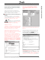
Changing the dialog language
Now the SyncPos window has been opened –
English is the standard dialog language.
O.ERR 13 can only be reset using the ERRCLR
command or with "BREAK" [ESC] in the PC software and only when the VLT ist in the "ready" state,
which means none of the above may be true.
■ VLT optimisation
To achieve good control it is important to optimise
the VLT. This must be done before positioning or
synchronising using SyncPos.
Some VLT parameter factory settings are, when
SyncPos is mounted, different to the standard
factory settings. A fulle list is included in the SyncPos
instruction manual. The instruction manual is
included on the SyncPos CD. Note that the ramp
times are as short as possible because they act as
a filter on the PID loop of SyncPos.
■ Safety tips
The controller and the motor must be
able to be switched off at any time with
an EMERGENCY STOP button.
The motor must be able to turn completely freely so that a sudden jolt can not
cause damage.
■ Installing SyncPos
Insert the CD in the CD ROM drive, in
the menu click on "INSTALL VLT
SOFTWARE SYNCPOS", and "RUN THIS
PROGRAM FROM ITS CURRENT LOCATION"
and click yes.
8
If you desire another language, click on "SETTINGS"
→ "LANGUAGE" (before you open a file) and select
for example "GERMAN" in the dialog field which will
subsequently appear. "EXIT PROGRAM" and start
SyncPos again.
Exit SyncPos
You can only abort or end an APOS program with
[ESC]. In order to do this the file which is linked with
resp. VLT must be open.
■ Setting of VLT parameters
During booting the VLT parameters are set to the
factory settings. Only the motor parameters remain
to be set:
Perform AMA (see VLT 5000/VLT 5000 Flux manual)
or manual optimizing of the VLT to the connected
motor.
Adjust maximum output frequency in par. 202 (Flux:
output speed high limit) and maximum reference in
par. 205 according to maximum velocity of the
encoder. Note that the maximum output frequency
must be higher than the frequency corresponding to
maximum allowed velocity of the shaft because of
the slip of the motor.
Terminal 27 must be connected to 24 V or parameter 502 must be set to ”serial port”.
MG.10.Q1.5B – VLT is a registered Danfoss trade mark
VLT 5000/5000 FLUX SyncPos Quick-Setup
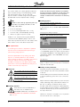
Press "ok" to confirm interruption of program.
Choose parameter group Encoder. The factory
default setting of encoder resolution is 500 as
shown.
Checking encoder connections
Function of inputs and output must be selected in
parameter group 3xx according to the required
functions. Note that the default values are different
from a drive without option.
Please note that Dead Time Compensation in
parameter 780 (not Flux) is set to OFF. This parameter is to prevent oscillation at standstill.
■ Checking encoder connection and direction of
rotation
If you have not yet done so, now is the time to
connect and test the encoder. In this example it is
assumed an incremental encoder is used.
NB!
Remember to turn off the power before
connecting the encoder. See "Technical
Data/Wiring examples" for encoder wiring.
Preparation for first run
To be able to communicate with the SyncPos option
please observe the application example regarding
the wiring of the RS 232 to 485 converter.
Please note that outputs of both the VLT and
SyncPos may change, hence control of mechanical
brake or such may be interrupted.
Enter the correct value in pulses per revolution and
press ok.
Check the encoder connections by means of the
encoder test program. In the menu bar click on
"FILE" and "OPEN" the file Enc-S.m
Enc-S.m, which is the
first test program for starting operation.
Next, there are only 2 important parameters for
testing the encoder connection and rotation. One is
the Proportional gain factor of the SuncPos PID
loop. This parameter is accessible via the LCP
parameter 702. The other is the encoder resolution
parameter (ENCODER). To access the ENCODER
parameter click "CONTROLLER", "PARAMETERS",
and "AXIS".
First set parameter 700 = "2". In the
"DEVELOPMENT" menu click on "EXECUTE" in order
to start the test program or press F5. The position 0 is
registered in the communications window.Run the
MG.10.Q1.5B – VLT is a registered Danfoss trade mark
9
Checking encoder connections
VLT 5000/5000 FLUX SyncPos Quick-Setup
drive forward for example in local mode (Parameter
002 = ”Local”) then the position must count positive. If
the position is counting negative you must swap A and
B channels from the encoder or two motor phases.
You can also turn the encoder by hand (the motor
should not be connected!). The position is
continuously registered in the communications
window. For a full rotation you should receive 4
times the value of the resolution of the encoder, that
means 2000 if the Encoder pulses per revolution is
500.
Ending the encoder check
End the test of the encoder with the [ESC] key and
close the test program with "FILE" → "CLOSE". A
successful test of the encoder is a requirement for
further starting up of operations.
If the encoder doesn’t work
If the VLT parameter 002 is "LOCAL" please change
it = "REMOTE". Click on "DEVELOPMENT" and
start the test program with "EXECUTE" or [F5].
The test is successful if the motor runs slowly back
and forth and position 500 is registered.
End the test with [ESC] and "CLOSE" the "FILE".
If the motor doesn’t move
If the motor doesn’t move at all, then the proportional factor of the PID filter is probably too low or
the VLT has not been enabled. Another possibility
is that the encoder resolution is high. Therefore
we recommend to change line 17 "POSA500" to
be half the encoder resolution in quadcounts.
E.g. encoder ppr is 4096. Line 17 should be
changed to (4096 x 4/2) "POSA 8192".
Check the VLT enable (terminal 27 = 24 V) and
check that the VLT wasn't stopped via the LCP
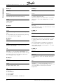
(flashing display). Then increase the Proportional
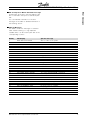
factor (parameter 702). (See following chart).
Encoder ppr (ENCODER)
This could be a result of incorrect cable installation. Measure the signals coming from the
encoder and compare them to the values listed in
the specifications. Check whether the connection
was made according to the application.
■ Execute the test run program
Now connect the motor to the VLT, make sure
that the motor can turn completely freely.
NB!
The motor must be provided with an
[EMERGENCY STOP] button.
NB!
Turn off the motor immediately with
the EMERGENCY STOP button if it
vibrates heavily or sets off uncontrolled.
Click on "FILE" and "OPEN" the file Move-S.m
Move-S.m.
10
500
Proportional (KPROP) par 702
200
512
200
1000
100
1024
100
2000
50
2048
50
2500
50
3600
25
4096
25
5000
25
If the encoder is not mounted on the motor please
note the gear-ratio between motor and encoder.
Use this ratio to multiply the Proportional factor. E.g.
motor turns 2 rev. encoder turns 1 rev. ratio is 1:2.
Multiply the Proportional factor with 2.
If the motor vibrates heavily...
… then you have to: reduce the Proportional
factor KPROP (11). If the drive stops due to a “O.
Err. 8 in the LCP" then it is necessary to increase
the Tolerated position error POSERR (15). (See 10
steps to optimise the PID loop).
MG.10.Q1.5B – VLT is a registered Danfoss trade mark
VLT 5000/5000 FLUX SyncPos Quick-Setup
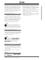
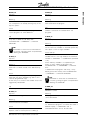
1.
2.
3.
4.
5.
6.
7.
8.
9.
10.
Setup of VLT parameters (AMA)
SyncPos PC software installation and starting
Setup of serial communication
Setup of SyncPos parameters
Check encoder connection and direction of
rotation
Execute testrun via SyncPos PC software
Optimise PID controller of SyncPos
Install software (APOS user program)
Test functionality of user program
SUCCESS
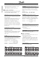
■ How the control process works
The "TESTRUN" explained in the chapter
PC Software Interface of the SyncPos manual
found on the CD can be used as a tool to optimize the SyncPos controller settings, thereby
optimizing your system performance. To do that
you only need to know a few things about the
control scheme of SyncPos:
The SyncPos position controller has two parts:
1. The Setpoint Generator interprets the various
positioning commands in SyncPos and generates a series of setpoint positions that eventually ends with the desired position.
Normally, all positioning processes have a
trapeze-shaped velocity curve. That means
that after a phase of constant acceleration
there is a phase with constant velocity and
finally a phase with constant deceleration,
which ends at the desired target position.
2. The PID controller receives the setpoint positions from the Setpoint generator and in turn
calculates the speed reference needed for
the motor to follow the current setpoint
position.
By setting the PID control parameters you
can directly influence to what degree and ■
Significance and influence of the control
parameters
MG.10.Q1.5B – VLT is a registered Danfoss trade mark
quickly a deviation from a theoretical set path (as
specified by the setpoint series) should be
counteracted.
The following behavior indicate that the control parameters are not optimally adjusted:
• Drive vibrates
• Drive is loud
• Frequent occurrence of position errors
• Poor control accuracy
NB!
The control parameters are load-dependent.
Thus the drive must be optimized under the
actual conditions of use.
In exceptional cases it may be necessary to determine various sets of control parameters while working with heavily changing load conditions and to reprogram them in subsequent application programs
depending on the motion process.
■ Significance and influence of the control
parameters
The PID control unit of the SyncPos option transfers
the necessary output frequency via an internal
speed reference to the VLT. This set value is periodically re-calculated with an interval of one millisecond
(interval is programmable by the TIMER parameter).
The SyncPos option is by default set with soft 'fit for
all' controller parameters.
The PID filter works according to the following
formula:
① = FFVEL * (Setpoint velocity)
② = FFACC * (Setpoint acceleration)
③ = KPROP * (Position deviation)
④ = KINT * (Sum of all previous position deviations) (limited by KILIM)
⑤ = KDER * (Velocity of position deviation)
⑥=③+④+⑤
(limited by BANDWIDTH)
11
10 steps to optomise the PID loop
■ Commissioning Guideline
When the APOS user program is written and it is
time to impelment it in a given application it is a
godd idea to have a plan of attack. Below is a list
with 10 steps to success with SyncPos. It does
not make sense to download the APOS user
program and run the machine before the VLT and
SyncPos parameters are correctly set. If
something goes wrong during commissioning the
troubleshooting guideline can be used to assist in
the faultfinding.
10 steps to optimise the PID loop
VLT 5000/5000 FLUX SyncPos Quick-Setup
AV is the actual velocity
AP is the actual position (calculated from encoder
feedback) in qc (Quad Counts).
CP is the current Setpoint position in qc.
CV is the Setpoint velocity in qc/ms.
(Position deviation) is calculated by CP–AP.
NB!
In SYNCV mode the PID controller is working
with speed deviation instead of position
deviation. Speed deviation is calculated by CV–AV.
The controller in the SyncPos card utilizes two
control strategies at the same time:
1. An open-loop feed-forward control. Since the
asynchronous motor inherently has a good
open loop performance the feed-forward control is a very important part of the controller in
most applications. Benefits from using feedforwards control is a very fast and accurate
response to changes in the setpoint reference.
2. A closed-loop PID control. The PID controller
monitors the difference between the actual
position and the setpoint position. Based on this
information it calculates a control signal to
minimize the position deviance. Thus the
SyncPos option is able to compensate for
changes in load or friction. The PID controller is
also necessary to compensate for any position
deviance caused by inaccurate setting of the
open-loop feed-forward controller.
In short: The feed-forward control is used to handle
changes in the setpoint reference (especially important in synchronization applications), while the PID
control is used to handle changes in load conditions
or inaccuracies of the feed-forward control.
Proportional factor KPROP (11)
The Proportional factor is multiplied with the position deviance and the result is added to the control
signal (the internal speed-reference to the VLT).
Since the calculated control signal is proportional to
the position deviance (or error) this kind of control is
called proportional control. The behavior of the
proportional control is similar to that of a spring – the
further the spring is extended the stronger the
counter-force it produces.
Influence of the Proportional factor
factor:
KPROP too small large position deviation due to
non-compensatable load and
frictional moment;
12
KPROP larger
quicker reaction, smaller steadystate deviation, larger overshoot,
lesser damping;
KPROP too great heavy vibrations, instability.
Derivative factor KDER (12)
The Derivative factor is multiplied with the derivative
of the position deviance (the 'velocity' of the position
deviance) and the result is added to the control
signal. The behavior of the derivative control is
similar to that of an absorber – the faster the
absorber is extended the stronger the counter-force
it produces. Thus using the Derivative factor
increases damping in your system.
Influence of the Derivative factor
factor:
KDER small
no effect;
KDER larger
better dampening, lesser overshoot; if KPROP is increased
simultaneously: faster reaction to
control deviation at the same
level of vibration;
KDER too large
heavy vibrations, instability.
Integral factor KINT (13)
The sum of all error is calculated every time the
control signal is updated. The Integral factor is then
multiplied with the sum of all positioning errors and
added to the overall control signal. Thus in case that
steady-state position errors occurs in your
application, make sure you use the integral part of
the controller. Steady-state errors will be levelled out
as the summed error increases over time until the
control signal eventually matches the load.
It is possible to set a limit for the control signal
generated by the integral part of the controller (antiwindup).
Influence of the Integral factor
factor:
KINT very small
steady-state position deviance is
very slowly regulated to zero;
KINT larger
faster regulation towards zero
steady-state position deviance,
larger overshoot;
KINT too large
heavy vibrations, instability.
Integration limit KILIM (21)
The Integration limit sets a limit for the control signal generated by the integral part of the controller.
This helps to prevent the so called "wind-up" problems which typically occurs in applications where
the overall control signal (the internal speed-reference) is maxed out for long periods of time.
MG.10.Q1.5B – VLT is a registered Danfoss trade mark
VLT 5000/5000 FLUX SyncPos Quick-Setup
Velocity Feed-forward FFVEL (36)
The Velocity feed-forward factor is a scaling factor
that is multiplied with the derivative of the setpoint
position (the velocity of the setpoint). The result of
this operation is added to the overall control signal.
This feature is especially useful in applications where
there is a good correlation between the control
signal (the VLT speed reference), and the speed of
the motor. This is indeed the case with most
applications using an asynchronous motor.
But if you are operating a system which could be
jeopardized by vibrations, for example, a crane
with a heavy load then you can limit the bandwidth
in which the PID controller should function.
BANDWIDTH (35) of 300 makes a limitation of 30%
possible. The build-up of a vibration is thus prevented since the control is only moved to with 30%
of the calculated set value.
However, then it is necessary also to use the feedforward part of the controller in order to achieve
the corresponding control.
NB!
The scaling of the FFVEL parameter is dependent on the correct setting of the maximum reference (VLT parameter #205) as well as the
SyncPos parameters VELMAX (1) and ENCODER
(2).
Acceleration Feed-forward FFACC (37)
The Acceleration feed-forward factor is multiplied
with the 2nd derivative of the setpoint position (the
acceleration of the setpoint) and the result is added
to the control signal. This feature should be used to
compensate for the torque used to accelerate/
decelerate the system inertia.
NB!
Scaling of the FFACC factor is depending on
the setting of the Shortest ramp time (31).
You should therefore increase the FFACC accordingly when decreasing SyncPos parameter
Shortest ramp time (31) and vice versa.
Sampling time for the entire control algorithm TIMER
(14)
For particularly slow systems you can slow down
the entire control system by entering multiples of
1 ms as the sampling time. However, it is important
to remember that such a change influences all the
control parameters!
Therefore, normally you should not deviate from
the value of 1 ms.
BANDWIDTH
A Bandwidth of 1000 means that the set value is
being executed 100%, thus Derivative
Derivative, Proportional and Integral factors are effective as defined.
MG.10.Q1.5B – VLT is a registered Danfoss trade mark
13
10 steps to optomise the PID loop
This feature is also very helpful in applications where
the power to the motor is turned off and on while the
option card is controlling the VLT. Cutting of power to
the motor (by setting terminal 27 low) while little positioning deviance is present in the controller, could result
in an enormous control signal being generated once
the power is turned back on.
10 steps to optimise the PID loop
VLT 5000/5000 FLUX SyncPos Quick-Setup
■ Optimizing your controller settings
step-by-step
For best results use the functions in the testrun
menu for this purpose; these help you to evaluate
and optimize the PID controller on the basis of
graphs of the set and actual curves.
However, we recommend only changing one value
at a time and subsequently determining the improvement with a testrun..
Ten steps to optimise the PID loop
The following procedure will optimize your controller settings in most applications:
1. Make sure that you have specified correct
values for VLT parameter #205, as well as the
SyncPos parameters VELMAX (1), ENCODER
(2) and RAMPMIN (31). If you change these
settings again at a later point you may need to
optimize the controller again.
2. Set the POSERR (15) parameter to a very high
value e.g. 1000000 to avoid getting the option
error no. 8 during the following tests.
Click on "CONTROLLER" → "PARAMETER" →
"AXIS" and select the VLT, of which you are
currently adjusting the settings.
Setting controller behavior
Before you adjust the controller parameters it is
important to determine which controller behavior
should be achieved.
NB!
The drive elements must never be operated
outside of the technical specifications. Thus
the maximum acceleration is determined by the
“weakest” drive element.
• “Stiff” axis: the fastest reaction possible is
mainly influenced by the Proportional factor
factor.
You can judge the results on the basis of the
velocity graph.
• Damping of vibrations are mainly influenced
by the Derivative factor
factor. The results can best
be assessed in the velocity graph.
• Temporary (static) deviations in position are
mainly reduced by the Integral factor and
can best be judged on the basis of the positioning graph.
NB!
To avoid damaging the system, make sure, that
you set the POSERR within the limits of the
system.
3. Optimize the Velocity feed-forward control:
Auto feed-forward calculation:
The FFVEL can be calculated hence it is not
needed to perform a testrun to optimise the
FFVEL. For VLT 5000 process the following
formula applies:
FFVEL = (62914560000 * P104) / (Vnom * Eres
* Tsample * P205)
P104: Denotes the value of the VLT 5000
parameter 104 (nameplate motor frequency)
P205: Denotes the value of the VLT 5000
parameter 205 (maximum reference)
Vnom: Is the nominal encoder velocity at
nominal motor frequency. The unit is RPM.
Eres: Is the number of quad-counts per
encoder revolution. If an absolute encoder is
used the unit is steps (positions) per revolution.
Tsample: Is the PID controller sampling interval
(TIMER).
For VLT 5000 Flux the following formula
applies:
FFVEL = (62914560000 / Eres * Tsample *
Vmax)
Eres: Is the number of quad-counts per
encoder revolution. If an absolute encoder is
used the unit is steps (positions) per revolution.
Tsample: Is the PID controller sampling interval
(TIMER).
14
MG.10.Q1.5B – VLT is a registered Danfoss trade mark
VLT 5000/5000 FLUX SyncPos Quick-Setup
FFVEL is now optimized, save the current value.
Please note that some high inertia systems do
not allow the use of FFVEL.
4. In systems with large inertia and/or rapid changes
in the reference velocity it is a good idea to use
and optimize the Acceleration feed-forward
control (make sure the inertial load is connected
when optimizing this parameter):
Step 1)
Execute a "TESTRUN" with KPROP=0,
KDER=0, KINT=0, FFACC=0 and FFVEL at the
optimized value calculated above. Use the
highest possible acceleration setting. If
RAMPMIN (31) is adjusted properly an
acceleration value of 100 and a deceleration
value of 100 should be sufficient. Start out with
a low setting of FFACC approx. 10.
Step 2)
View the velocity profiles: If during acceleration
the actual velocity is constantly lower than the
reference velocity profile, then click "REPEAT"
and set a higher value of FFACC. Then execute
"TESTRUN" again.
Step 3)
Run successive TESTRUNs until the two velocity profiles shown in the TESTRUN graph have
similar ramp-up and ramp-down curves.
Step 4)
FFACC is now optimized, save the current
value.
5. Next step is finding the maximum stable value
of the Proportional facto
factor in the PID controller:
Step 1)
Execute a "TESTRUN" with KPROP (calculated
FFVEL/50), KDER=0, KINT=0. Set FFVEL and
FFACC at the optimized values found above.
Step 2)
View the velocity profile. If the velocity profile
isn't oscillating then click "REPEAT" and
increase KPROP else reduce KPROP and
repeat.
Step 3)
Run successive TESTRUNs until the actual
velocity profiles is oscillating mildly. Save this
value.
MG.10.Q1.5B – VLT is a registered Danfoss trade mark
10 steps to optomise the PID loop
Vmax: Is the maximum encoder velocity. The
unit is RPM. If the SyncPos feedback encoder is
motor mounted then parameter 205 must be
equal to Vmax.
6. In order to dampen the oscillations created
by the KPROP-part of the controller, the
Derivative factor should now be optimized.
Step 1)
Execute a "TESTRUN" with KINT=0 and
KDER=5*KPROP. Set FFVEL, FFACC and
KPROP at the optimized values found above.
Step 2)
Run successive TESTRUNs with increasing
values of the KDER factor. At first the oscillations will gradually reduce. Stop increasing
KDER when the oscillations begin to
increase.
Step 3)
Save the last value of KDER.
7. In any system that requires a close to zero
steady-state error, the integration part of the
controller must be used. Setting this
parameter though is a trade-off between
achieving zero steady-state error fast and
increasing overshoot and oscillations in the
system.
8. If you are using the integration part of the
PID controller, remember to reduce the
KILIM as much as possible (without losing
the KINT-effect of course) in order to reduce
oscillations and overshoot as much as
possible.
9. Reduce the BANDWIDTH only if the system
has a tendency to vibrate. With a properly
optimized open-loop control BANDWIDTH
could be reduced to as little as 6 to 12 %.
10. Set the POSERR (15) parameter back to
normal e.g. 20000.
"TEST PARAMETER" → "SAVE"
Once you have concluded the "TESTRUN" →
"SAVE" the new parameters as the user parameters. Thus, these parameters are saved in the
controller and in the future will be used for all
programs.
■ What to do if...
... there is a tendency towards instability
In the event of a strong tendency towards instability reduce the proportional and derivative
factors again, or reset the integral factor.
... stationary precision is required
If stationary precision is required then you must
increase the integral factor.
15
10 steps to optimise the PID loop
VLT 5000/5000 FLUX SyncPos Quick-Setup
... the tolerated position error is exceeded
If the test run is constantly interrupted with the
message “position error” set the parameter for
the Tolerated position error POSERR (15) –
within the tolerable limits– as large as possible.
If the position error occur during the acceleration
phase that suggests that the set acceleration
cannot be achieved under the existing load
conditions. Increase the Tolerated position error
POSERR (15) or determine a maximum
acceleration suitable for the entire system.
If position error do not occur until after the acceleration phase and they can be delayed but not
eliminated by increasing the Tolerated position
error
error,, this suggests that the maximum velocity
(rpm) chosen is too high. Determine a maximum
velocity suitable for the entire system.
.. the maximum acceleration is not achieved
In general, the technical data for a drive are only valid for a freely rotating axle end. If the drive is carrying a load the maximum acceleration is reduced.
The theoretical maximum acceleration will also
not be achieved if, for example, the PID controller
output is too small or the VLT/motor is not sized
correctly and therefore does not provide enough
energy for peak consumption during acceleration.
16
MG.10.Q1.5B – VLT is a registered Danfoss trade mark
VLT 5000/5000 FLUX SyncPos Quick-Setup
Error messages
■ VLT and SyncPos Motion Controller messages
All messages are shown in the LCP display of the
VLT in short and in the SyncPos software in plain
text.
You can find brief information on the error
messages in the table or detailed information in
the following section.
■ Table of Messages
The tables contain the messages in numerical
order. Letters following a % sign represent
variables which can be used in plain text at the
corresponding locations.
O.ERR_
3
5
6
7
8
9
10
11
12
13
14
16
17
18
19
25
49
51
52
62
70
71
79
84
87
90
91
92
xx
LCP-Display
AXES NOT IN SYSTEM
ERROR NOT CLEARED
HOME NOT EXECUTED
HOME_VEL ZERO
POSITION ERROR
INDEX NOT FOUND
UNKNOWN COMMAND
SOFTWARE LIMIT ACT.
ILLEGAL PARAMET. NO
General VLT error
TOO MANY NEST. LOOP
PARAM. ERROR EEPROM
PROGR. ERROR EEPROM
RESET BY CPU
USER ABORT
LIMIT SWITCH ACTIV.
TOO MANY INTERRUPTS
TOO MANY NEST. GOSUB
TOO MANY RETURN
ERROR IN VERIFYING
ERROR IN DIM COMMD
ARRAYBOUNDS CROSSED
TIMEOUT WAITNDX
TOO MANY ONTIME
OUT OF MEMORY (VAR)
MEMORY locked
ILLEGAL CURVE ARRAY
ENCODER ERROR
INTERNAL ERROR
MG.10.Q1.5B – VLT is a registered Danfoss trade mark
SyncPos message
Axis no. %bu not in system
Axis no: 1 Error not cleared
Axis no: 1 Failed to move to HOME position
Axis no: 1 Home vel 0
Axis no: 1 Position error
Axis no: 1 Index pulse (encoder) not found
Unknown command
Axis no.1 Software limit switch activated
Illegal parameter number
General VLT error
Too many nested loops
Parameters in EEPROM are corrupted
Programs in EEPROM are corrupted
Reset by CPU
User abort
Axis no. 1 Limit switch activated
Too many interrupt functions
Too many nested GOSUB commands
Too many RETURN commands
EEPROM: address % defect
Error in DIM command
Attempt was made to cross arraybounds
Timeout while waiting for index
Too many time interrupts
No more room for variables
The program memory is write-protected.
Curve array wrong
Error from encoder monitoring
Internal error ##
17
Error messages
VLT 5000/5000 FLUX SyncPos Quick-Setup
■ SyncPos option messages in detail
As in the table above, the messages are in numerical order. Here you can find additional information
about possible causes and tips on troubleshooting.
O.ERR_3
SyncPos
Axis no. %bu not in system
Cause
An attempt has been made to find another axis
which does not exist in the controller. (The program
allows for input of axis numbers greater than 1
since it is configured for multi-axes applications.)
Tip
Check to see if the program axis command has an
invalid number or a general axis command (...X(*)).
O.ERR_5
SyncPos
Axis no: 1 - Error not cleared
Cause
An attempt has been made to execute a motion
command, although a momentary error message
has not been cleared.
O.ERR_6
SyncPos
Axis no: 1 - Failed to move to HOME position
Cause
According to the axis parameter HOME_FORCE
(3), a forced move to the machine zero-point is demanded, before other motion commands can be
executed. This move to the machine zero-point has
not been executed.
O.ERR_7
SyncPos
Axis no: 1 - Home vel 0
O.ERR_8
SyncPos
Axis no: 1 - Position error
Meaning
The distance between the set and the real position
was greater than the Tolerated position error
defined in parameter POSERR (15).
Cause
Mechanically blocked or overloaded drive,
Tolerated position error POSERR (15) too small,
commanded speed greater than VLT Parameter
202 and 205,
commanded acceleration too great,
Proportional factor KPROP (11) too small or
VLT not enabled.
O.ERR_9
SyncPos
Axis no: 1 - Index pulse (encoder) not found
Meaning
At reference resp. index search, the encoder index
pulse could not be found within a motor rotation.
Cause
An encoder without an index pulse has been used,
index pulse not connected correct,
index pulse incorrect (all three channels must have
a simultaneous low) or
the parameter ENCODER (2) is set too low.
O.ERR_10
SyncPos
Unknown command
Cause
A communication or program error.
Tip
The program must be re-compiled and re-loaded.
Cause
HOME was executed with HOME_VEL set to zero.
18
MG.10.Q1.5B – VLT is a registered Danfoss trade mark
VLT 5000/5000 FLUX SyncPos Quick-Setup
Cause
A motion command will cause / has caused the
software limit switch to be activated.
Tip
Identification of attainment of software limit at a
motion in the speed mode will only be made after
the current position is identical to the software limit
switch.
The control unit will be switched off and the drive
must be manually moved back to within the
admissible area, or the monitoring of the software
limit switch must be temporarily de-activated via
the axis parameter SWPOSLIMACT (20) resp.
SWNEGLIMACT (19). Only then is it possible to
clear the error.
In positioning mode, it will be known before motion
start that the target position lies outside the path.
In this case, the movement will not be executed
and the error message can be cleared.
O.ERR_12
SyncPos
Illegal parameter number
Cause
An attempt has been made to change a parameter
(SET or SETVLT command), which does not exist.
O.ERR_13
SyncPos
General VLT error
Cause
Every 20 ms the VLT status is tested and in the
event of an error status this fault alarm is given.
Bits with the value of 512 and 2048 are checked.
This test only takes place in the controlled status,
not at MOTOR OFF and not when parameter 700
is deactivated.
Error messages
O.ERR_11
SyncPos
Axis no. 1 Software limit switch activated
O.ERR_14
SyncPos
Too many nested loops
Cause
Too many nested loops exist in the executed
program.
O.ERR_16
SyncPos
Parameters in EEPROM are corrupted
Meaning
The parameters in EEPROM are no longer correct.
Cause
EEPROM defective or
power outage while saving.
Tip
You have to re-initialize the parameter with
"CONTROLLER" → "PARAMETERS" → "RESET"
and then overwrite these parameters with your own
user parameters. Otherwise motion programs
which require user parameters will no longer
function correctly.
O.ERR_17
SyncPos
Programs in EEPROM are corrupted
Meaning
The program data stored in EEPROM cannot be
found resp. are no longer correct.
Cause
EEPROM defective or
power outage while saving.
Tip
Delete the EEPROM with "CONTROLLER" →
"MEMORY" → "DELETE EEPROM" and then reload the programs and parameters.
Note
You can enquire in the VLT status as to the exact
cause of the fault alarm (e.g. „Trip“ or „Not ready“).
MG.10.Q1.5B – VLT is a registered Danfoss trade mark
19
Error messages
VLT 5000/5000 FLUX SyncPos Quick-Setup
O.ERR_18
SyncPos
Reset by CPU
O.ERR_51
SyncPos
Too many nested GOSUB commands
Meaning
The processor has been stopped and a re-set has
automatically been executed (watchdog).
Cause
In the program, too many calls from one subroutine
to another subroutine exist.
The error usually occurs when there is a recurrent
reference to one of the sub-programs in a subprogram.
Cause
Short term voltage drop,
voltage peak or
short circuit.
O.ERR_19
SyncPos
User-Abort
Cause
The autostart-program has been aborted by the
user.
Or the [CANCEL] key was pressed during switching
on and a Master Reset triggered.
O.ERR_25
SyncPos
Axis 1: Limit switch activated
Cause
A motion command has caused an axis limit
switch to be activated.
Tip
Through activation of a limit switch, the controller –
depending on the parameter ENDSWMOD (44) –
is automatically switched off and the drive must be
manually moved out of this position, before the
error message can be cleared.
O.ERR_49
SyncPos
Too many interrupt functions
Cause
More interrupt functions than the maximum
possible number were used …
Tip
Avoid too many (10 is maximum) opposing subroutine calls,
avoid subroutines which call themselves (re cursive
subroutine procedures).
O.ERR_52
SyncPos
Too many RETURN commands
Cause
There are either more RETURN than corresponding GOSUB commands in the program, or there
is a direct jump from a subroutine with a GOTO
command.
Only one RETURN is allowed per sub-program.
It is always better to jump to the beginning of a
sub-program and then to jump with IF… to a previously defined label.
O.ERR_62
SyncPos
Error in verifying
Meaning
After saving something in the EEPROM (a program
or parameters) an error was detected during verification.
Tip
Delete the EEPROM with "CONTROLLER" →
"MEMORY" → "DELETE EEPROM" and try to
save the program or parameters again. If this is not
successful please call the technical service
department.
Tip
…permitted are:
32 ON INT
32 ON STATBIT
32 ON COMBIT
10 ON PARAM
20 ON APOS, ON MAPOS, ON MCPOS
20
MG.10.Q1.5B – VLT is a registered Danfoss trade mark
VLT 5000/5000 FLUX SyncPos Quick-Setup
O.ERR_84
SyncPos
Too many time interrupts
Meaning
The definition of an array in a DIM command does
not correspond to an already existing array in the
SyncPos option.
Meaning
Too many ON TIME or ON PERIOD commands
were used within the program.
Cause
The fields are from older SyncPos programs. The
current program has other definitions.
Tip
Either adapt the SyncPos program to the correct
array size or delete the old arrays with
"CONTROLLER" → "MEMORY" → "DELETE
EEPROM".
NB!
Remember to follow the recommendations
concerning saving programs and parameters
before deleting the EEPROM.
O.ERR_71
SyncPos
Attempt was made to cross arraybounds
Meaning
An attempt was made to describe an array element that is located outside of the defined array
limits.
Cause
Error in the SyncPos program. Array sizing does not
agree with the space required (e.g. due to an incorrectly programmed loop).
Or the array is too small for the number of test runs
triggered by TESTSTART.
Tip
Check loop variables.
O.ERR_79
SyncPos
Timeout while waiting for index.
Meaning
The command WAITNDX was executed and the
timeout listed was exceeded.
Cause
The timeout is probably too short or the index
impulse could not found (see also O.ERR_9).
MG.10.Q1.5B – VLT is a registered Danfoss trade mark
Error messages
O.ERR_70
SyncPos
Error in DIM command
Tip
A maximum of 12 of these ON TIME and/or ON
PERIOD commands are allowed within one
program..
O.ERR_87
SyncPos
No more space for variables
Meaning
When the SyncPos program is started the space
for the necessary variables is reserved dynamically.
This space is now no longer available.
Cause and tip
You may have selected a maximum number of
variables which is too high. Reduce the maximum
number in "SETTINGS" → "COMPILER" (Standard
= 92).
Or the memory available is occupied with programs or arrays. Delete the programs with
"CONTROLLER" → "PROGRAMS" → "DELETE
ALL"
or delete both the programs and arrays, i.e. by
deleting the entire memory with "CONTROLLER"
→ "MEMORY" → "DELETE EEPROM"..
NB!
Remember to follow the recommendations
concerning saving programs and parameters
before deleting the EEPROM.
O.ERR_90
SyncPos
MEMORY locked
Meaning
The program memory is write-protected and
cannot be altered.
Tip
This means that autorecognition can neither be set
nor deleted and programs can neither be saved or
deleted. Equally, → "RAM SAVE" and →
"EEPROM DELETE" will not be executed.
21
Error messages
VLT 5000/5000 FLUX SyncPos Quick-Setup
O.ERR_91
SyncPos
Curve array wrong
Meaning
An incorrect or old array is defined in the DIM
instruction for SETCURVE.
Tip
An old array may exist if the cnf file with all parameters and arrays has not been loaded into the
CAM-Editor.
An incorrect array could be caused by the
following:
• It was not created by the curve editor.
• Previous version of a curve editor. Such an array must first be converted by the current
curve editor (→ "LOAD" and "SAVE").
• Or the order of the arrays in the DIM instruction does not match the order in the cnf file.
Refer to the number of the array in the title
bar of the CAM-Editor in this respect.
O.ERR_92
SyncPos
Error from encoder monitoring
Meaning
Open or short circuit in accordance with the displayed LED
NB!
An error will be indicated even if no encoder
is connected.
O.ERR_xx
SyncPos
Internal error ##
Meaning
If such an error should occur, please contact your
dealer and report the error number displayed to
the technical service department.
22
■ VLT software SyncPos messages
The VLT software SyncPos messages are arranged
in alphabetical order. Letters following a % sign
represent variables which can be used in plain text
at the corresponding locations.
■ Compilation error ...
SyncPos
Compilation error(s): program not saved!
Meaning and tip
A file is always compiled first and then saved. If
you want to save the program, for example in the
menu "CONTROLLER“ → "SAVE PROGRAM" and
a syntax error is found during compilation this
message will be displayed.
Start the “SYNTAX CHECK” in the menu
“DEVELOPMENT”, correct the syntax error and
then save the program.
■ Connection to ... already exists ...
SyncPos
Connection to %d already exists [%s] - change to
new Window?
Meaning
When opening a new window or when trying to
connect a window with a controller that is already
linked to a window.
Yes The controller is disconnected from the old
window and linked to the new window.
No The controller stays connected to the old
window, the new window is not linked to a
controller.
■ Controller is executing a program ...
SyncPos
Controller is executing a program or command!
Meaning
When the controller is executing a command or
program it is not available for additional commands. You have to → "BREAK" the new command and restart it once the previous command
has been completely executed.
MG.10.Q1.5B – VLT is a registered Danfoss trade mark
VLT 5000/5000 FLUX SyncPos Quick-Setup
■ Error in global parameter ...
SyncPos
Error in global parameter part of file.
Meaning
When re-saving a configuration ("CONTROLLER"
→ "PARAMETERS" → "RESTORE FROM FILE")
the computer recognizes that the data in the array
area is formatted incorrectly.
Meaning
When re-saving a configuration ("CONTROLLER"
→ "PARAMETERS" → "RESTORE FROM FILE")
the computer recognizes that the data in the area
of the global parameters is formatted incorrectly.
Cause
In order to be able to save a file, the following
conditions must be fulfilled:
• Identical software versions
• same configuration (e.g. same number of
axes)
• In the case that arrays have already been inputted, these must match the ones that are to
be saved in terms of type and size.
Causes
In order to be able to save a file, the following
conditions must be fulfilled:
• Identical software versions, that provides
same number and order of the parameters
• same configuration (e.g. same number of
axes)
■ Error in axis parameter ...
SyncPos
Error in axis parameter part of file.
Meaning
When re-saving a configuration ("CONTROLLER"
→ "PARAMETERS" → "RESTORE FROM FILE")
the computer recognizes that the data in the area
of the axis parameters is formatted incorrectly. The
parameter number and the sequence must be correct and numbering must be continuous.
Cause
In order to be able to save a file, the following
conditions must be fulfilled:
• Identical software versions, that provides
same number and order of the parameters
• same configuration (e.g. same number of
axes)
MG.10.Q1.5B – VLT is a registered Danfoss trade mark
■ Lost connection to ...
SyncPos
Lost connection to #%d!
Meaning
If the VLT is turned off or the plug is pulled, etc.
the window is disconnected from the VLT and the
lost connection is registered.
■ Timeout: no reply from VLT
SyncPos
Timeout: no reply from VLT
Meaning
The VLT does not answer; check the connection.
23
Error messages
■ Error in array ...
SyncPos
Error in array part of file.
Error messages
VLT 5000/5000 FLUX SyncPos Quick-Setup
There are two interfaces to the SyncPos option:
• 36 terminals on the option card
• 24 terminals on the VLT control card
■ VLT control card terminals
The terminals on the control card can be allocated
for synchronizing and positioning functions if the
following parameter settings are made:
Digital inputs 16, 17, 18, 19, 27, 29, 32 and 33:
It is always possible to read the status of the digital
inputs from the SyncPos application program with
the IN command.
If Parameter 300–303 and 305–307 are set to ”No
operation” (default setting) then the inputs are
ignored by the control card but they can still be
used as inputs to the application program.
Parameter 304 can not be set to ”No operation”
which means that input 27 always has a stop function. There is one way to avoid this: Leave parameter 304 at ”Coast inverse” and select ”Serial port” in
parameter 502.
Analogue inputs 53, 54 and 60:
It is always possible to read the value on the analogue inputs from the SyncPos application program
with the INAD command.
If parameters 308, 311 and 314 are set to ”No operation” then the inputs are ignored by the control
card but they can still be used as inputs to the
option card.
VLT5000: Digital/analogue outputs 42 and 45:
Outputs 42 and 45 can be controlled from the
SyncPos application program with the OUTDA
command, when parameters 319 and 321 are set
to one of the following four settings:
OPTION DIGITAL
[90] digital output
OPTION 0 … 20 mA [91] analogue output
(default setting)
OPTION 4 … 20 mA [92] analogue output
OPTION 0 … 32000P [93] pulse output
24
VLT5000Flux: Digital/pulse outputs 26 and 46
The outputs 26 and 46 on the VLT5000Flux control
card can be controlled from the SyncPos application
program with the OUTDA command when parameters 341 and 355 are set to one of the following
settings:
OPTION DIGITAL
[90] digital output
OPTION 0…50000P [91] pulse output
VLT5000Flux: Analogue outputs 42 and 45
The outputs 42 and 45 on the VLT5000Flux control
card can be controlled from the SyncPos application
program with the OUTDA command when parameters 319 + 321 are set to one of the following settings:
OPTION 0 … 20 mA [90] analogue output
0…20mA
OPTION 4 … 20 mA [91] analogue output
4…20mA
Relay outputs 01 and 04:
The relay outputs can be controlled from the
SyncPos application program with the OUT command when parameters 323 and 326 are set to the
default setting
CTRL WORD BIT 11/12
Technical data
Technical data on the control card terminals can be
found in the VLT 5000 design guide.
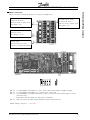
■ Option card terminals
There are two encoder interfaces which are covering the following functions:
• Feedback encoder input
• Master encoder input / virtual master output
There are 8 digital inputs, 8 digital output and terminals for 5 V and 24 V supply. The functions and
technical data of the terminals are described in the
following.
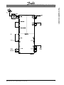
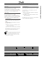
Terminal description
There are 4 terminal blocks, 2 with 10 poles and 2
with 8 poles. (See figure below)
Digital Inputs
Master / Virtual Master
Digital Outputs
Feedback
MG.10.Q1.5B – VLT is a registered Danfoss trade mark
VLT 5000/5000 FLUX SyncPos Quick-Setup
Encoder interface 2
MK3D is a 8pole terminal block with 6 terminals for
the encoder signals and 2 terminals with 5 V supply.
Digital outputs
MK3C is a 10pole terminal block with 8 digital outputs and 2 terminals for 24 V supply.
The digital outputs are controlled by the SyncPos
application program and are thus free programable.
All the outputs can also be assigned functions.
• Slave encoder input (incremental or absolute)
for synchronizing.
• Feedback encoder input (incremental or absolute) for positioning.
Encoder interface 1
MK3B is a 8pole terminal block with 6 terminals
for the encoder signals and 2 terminals with 5 V
supply.
Encoder interface 1 can be used for one of the
following 2 functions:
Encoder interface 2 can be used for one of the
following 2 functions:
The table below shows the function of each terminal
in the 2 possible modes. (See fig. 2)
• Master encoder input (incremental or absolute) for synchronizing.
• Virtual master encoder output (incremental).
The table below shows the function of each terminal in the 3 possible modes. (See fig. 1)
NB!
When using the virtual master function termination must be switched off (sw 1.3) in all
options except on the first and the last station
connected in the network.
Terminal
Incremental input
Absolute input
Virtual master
Fig. 1
A1
A in
Clk out
A out
A1
A in
Clk out
A out
B1
B in
Data in
B out
B1
B in
Data in
B out
Z1
Z in
Not used
Z out
Z1
Z in
Not used
Z out
Terminal
Incremental input
Absolute input
Fig. 2
A2
A in
Clk out
A2
A in
Clk out
B2
B in
Data in
B2
B in
Data in
Z2
Z in
Not used
Z2
Z in
Not used
MG.10.Q1.5B – VLT is a registered Danfoss trade mark
25
Technical Data/Wiring examples
Digital inputs
MK3A is a 10pole terminal block with 8 digital inputs
(I1–I8) and 2 terminals for 24 V supply.
The digital inputs are used by the SyncPos application program and are therefore free programable.
All the inputs can also be assigned functions:
Technical Data/Wiring examples
VLT 5000/5000 FLUX SyncPos Quick-Setup
■ Technical data
Terminals:
Type ................................................................................................................... Plugs with screw connections
Maximum cable size ............................................................................................................ 1.3 mm2 (AWG 16)
Digital inputs, MK3A:
Number of inputs which are used by SyncPos program ................................................................................ 8
Terminal designations .............................................................................................................................. I1 – I8
Voltage level .................................................................................................... 0 – 24 V DC (PNP positive logic)
Voltage threshold logical “0” .................................................................................................................. 5 V DC
Voltage threshold logical “1” ................................................................................................................ 10 V DC
Maximum voltage ................................................................................................................................ 28 V DC
Input impedance ........................................................................................................................................ 4 kΩ
Min. pulse duration (ON INT) ................................................................................................................. 1 msec
Galvanic isolation: All digital inputs are galvanically isolated by means of optocouplers,
but with the same common as the digital outputs.
Digital outputs, MK3C:
Number of outputs which are used by SyncPos program .............................................................................. 8
Terminal designations .......................................................................................................................... O1 – O8
Voltage level ................................................................................................................................... 0 – 24 V DC
Maximum load .............................................................................................. 0.7A (with external power supply)
Update rate ........................................................................................................................................... 1 msec
Galvanic isolation: All digital outputs are galvanically isolated by means of optocouplers,
but with the same common as the digital inputs.
External 24 V DC supply:
(see VLT 5000 manual)
Encoder input 1, MK3B (master):
Terminal designations ................................................................................................. A1, A1, B1, B1, Z1, Z1.
Incremental:
Signal level ................................................................................................................................... 5 V differential
Signal type ............................................................................................................................ Linedriver, RS 422
Input impedance .................................................................................................. 120 Ω (Dip switch 1.3 = ON)
....................................................................................................................... > 24 kΩ (Dip switch 1.3 = OFF)
Maximum frequency ........................................................................................... 220 kHz (at 50 % duty cycle)
Phase displacement between A and B ............................................................................................... 90° ±30°
Absolute:
Signal level ................................................................................................................................... 5 V differential
Signal type .................................................................................................................................................... SSI
Data coding ...................................................................................................................................... Gray code
Data length ............................................................................................................................................... 25 bit
Parity .......................................................................................................................................................... none
Clock frequency ....................................................................................................................... 105 or 260 kHz
Protocol ..................................................................................................................................................... Gray
Maximum positions per revolution ............................................................................................................. 8192
Maximum number of revolutions ............................................................................................................... 4096
26
MG.10.Q1.5B – VLT is a registered Danfoss trade mark
VLT 5000/5000 FLUX SyncPos Quick-Setup
Encoder cable:
Cable type ........ Twisted pair and screened. Note: Please observe the prescriptions of the encoder supplier
Cable length ...................................................................... Observe the prescriptions of the encoder supplier.
Absolute encoder is tested ok up to 150 meter cable at 105 kHz clock and 100 m at 262 kHz clock.
(Tested with TR electronic encoder type CE-65 M 8192*4096 and appropriate cable prescribed by TR electronic.)
Maximum allowed time delay between clock and data signal measured at the controller terminals ...............
.................................................................................................................................... 105 kHz clock = 9µsec
................................................................................................................................ 262 kHz clock = 3.5 µsec
Encoder output, MK3B:
Terminal designations ................................................................................................... A1, A1, B1, B1, Z1, Z1
Signal type ............................................................................................................................. Linedriver, RS485
Maximum frequency ............................................................................................................................. 150 kHz
Minimum frequency ................................................................................................................................ 150 Hz
Maximum number of slaves ........................................................................... 31 (more when using repeaters)
Maximum cable length ............................................................................................................................ 400 m
■ Connection examples
ABSOLUTE ENCODER
A2
A2
B2
B2
Z2
Z2
Master
Slave
MG.10.Q1.5B – VLT is a registered Danfoss trade mark
Master
Slave
27
Technical Data/Wiring examples
Encoder input 2, MK3D (slave):
Terminal designations ................................................................................................... A2, A2, B2, B2, Z2, Z2
Incremental:
Signal level ................................................................................................................................... 5 V differential
Signal type ............................................................................................................................. Linedriver, RS422
Input impedance ...................................................................................................................................... 120 Ω
Maximum frequency ........................................................................................... 220 kHz (at 50 % duty cycle)
Phase displacement between A and B ............................................................................................... 90° ±30°
Absolute:
Signal level ................................................................................................................................... 5 V differential
Signal type .................................................................................................................................................... SSI
Protocol ............................................................................................................................................ Gray code
Data length ............................................................................................................................................... 25 bit
Parity .......................................................................................................................................................... none
Clock frequency ....................................................................................................................... 105 or 260 kHz
Maximum positions per revolution ............................................................................................................. 8192
Maximum number of revolutions ............................................................................................................... 4096
Technical Data/Wiring examples
VLT 5000/5000 FLUX SyncPos Quick-Setup
■ Supply voltages:
The option card is supplied by the internal 24 V DC
supply of VLT 5000, but as the available power is
limited it can be necessary to use an external 24 V
DC supply.
The 24 V DC supply of VLT 5000 can supply a total
of 420 mA including the load on the control card
(terminal 12, 13 and output 42 and 45).
The 5 V output on the option card is generated from
the 24 V supply. The maximum power on the 5 V
side is 5 V * 280 mA = 1.4 W, this corresponds to
app. 60 mA on the 24 V side.
When an external 24 V DC voltage source is used
the internal 24 V supply from the control card must
be disconnected, this is done by opening switch 1.1
and 1.2
Each digital input on the option card takes 8 mA.
Each digital output on the option card can supply up
to 0.7 A (external 24V-supply) depending on the
load.
The load from the 24 V supply (internal or external)
can be calculated as follows:
■ Encoder monitor
Both encoder interfaces are equipped with a monitoring circuit that can detect open circuit as well as
short circuit of each encoder channel. Each
encoder channel has a LED showing the status:
Green light means ok, no light means fault. Zero
channel monitoring can be switched off by means of
switch 1.4, this is necessary when using incremental encoders without Zero channel or absolute
encoders. Switch 1.4 disables monitoring of both
master and slave Zero channel. If disabling of only
one of the two Zero channels is required (e.g. when
using incremental master encoder and absolute
slave encoder) the unused Zero channel input must
be connected to 5V/common as shown below.
8 mA * number of digital inputs
+
Load on digital outputs
(mk3 C, O1 – O8)
+
load on 5 V supply
(mk3 B/D, 5 V/com)
+
Load on control card
(24 V supply, terminal 12/13 and
outputs, terminal 42/45)
An encoder fault will only result in an ”Option error”
calling the error handler (ON ERROR) if encoder
monitoring is activated via parameter MENCODER
(master) and ENCODER (slave).
Note: Monitoring of the master encoder is disabled
when switch 1.3 is ”OFF”.
28
MG.10.Q1.5B – VLT is a registered Danfoss trade mark
VLT 5000/5000 FLUX SyncPos Quick-Setup
Encoder monitor master,
channel A, B and Z:
LED off = Short or open circuit
LED green = Ok.
Encoder monitor slave,
channel A, B and Z:
LED off = Short or open circuit
LED green = Ok.
5V monitor:
LED off = no 5V
LED Green = 5V ok.
CPU monitor:
LED must flash at 1 Hz to
indicate a running CPU system
SW 1.1:
SW 1.2:
SW 1.3:
SW 1.4:
Connect(ON)/disconnect(OFF) 24 V from control card (see description of supply voltages).
Connect(ON)/disconnect(OFF) 24 V common from control card.
Connect(ON)/disconnect(OFF) termination resistor for master encoder (see description of virtual
master function).
Note: When OFF the master encoder monitor is disabled.
Switch Z-channel encoder monitor ON/OFF for both master and slave.
Default setting of switch 1.1. - 1.4 is ON.
MG.10.Q1.5B – VLT is a registered Danfoss trade mark
29
Technical Data/Wiring examples
■ Option card layout:
Option card layout showing the position of connectors and dip switch.
Technical Data/Wiring examples
VLT 5000/5000 FLUX SyncPos Quick-Setup
The terminating resistors on both end of the
bus have to be switch on with dip switch
SW 1.3.
30
MG.10.Q1.5B – VLT is a registered Danfoss trade mark
VLT 5000/5000 FLUX SyncPos Quick-Setup
Technical Data/Wiring examples
left: encoder connection for positioning applications
below: encoder connection for master-/slave
synchronization
MG.10.Q1.5B – VLT is a registered Danfoss trade mark
31
Technical Data/Wiring examples
VLT 5000/5000 FLUX SyncPos Quick-Setup
Encoder connections for the synchronizing with
virtual master.
32
MG.10.Q1.5B – VLT is a registered Danfoss trade mark
VLT 5000/5000 FLUX SyncPos Quick-Setup
A
About this manual .......................................................... 3
Acceleration feed-forward FFACC (37) .......................... 13
APOS .................................................................. 4, 8, 11
K
KDER (12) ................................................................... 12
KILIM (21) .................................................................... 12
KINT (13) ..................................................................... 12
KPROP (11) .................................................... 10, 12, 18
L
B
LOOP .......................................................................... 17
BANDWIDTH (35) ............................................ 11, 13, 15
M
C
MAPOS ....................................................................... 20
Menus ........................................................................... 7
Messages
Attempt was made to cross arraybounds ................ 17
Axis no. ... not in system ........................................... 17
Compilation error ... .................................................. 22
Connection to ... already exists ... ............................. 22
Controller is executing a program ... .......................... 22
Curve array wrong .................................................... 22
Error from encoder monitoring ................................. 22
Error in array ... ......................................................... 23
Error in axis parameter ... .......................................... 23
Error in DIM command ............................................. 21
Error in global parameter ... ...................................... 23
Error in verifying ........................................................ 20
Error not cleared ...................................................... 18
Failed to move to HOME position ............................. 18
Illegal parameter number .......................................... 19
Index pulse (encoder) not found ................................ 18
Internal error ## ........................................................ 22
Limit switch activated ............................................... 20
Lost connection to ... ................................................ 23
No more space for variables ..................................... 21
Parameters in EEPROM are corrupted ..................... 19
Position error ........................................................... 18
Programs in EEPROM are corrupted ........................ 19
Reset by CPU .......................................................... 20
Software limit switch activated ................................. 19
Timeout while waiting for index. ................................ 21
Timeout: no reply from VLT ....................................... 23
Too many interrupt functions .................................... 20
Too many nested GOSUB commands ...................... 20
Too many RETURN commands ................................ 20
Too many time interrupts .......................................... 21
Unknown command ................................................. 18
User-Abort ............................................................... 20
MK3A .......................................................................... 25
MK3B .......................................................................... 25
MK3C .......................................................................... 25
MK3D .......................................................................... 25
MOTOR OFF ............................................................... 19
MOTOR ON ............................................................... 115
CAM-Editor ................................................................... 7
Connection examples ................................................... 27
D
Derivative factor KDER (12) ............................. 12, 14, 15
Digital inputs ......................................................... 25, 26
Digital outputs ...................................................... 25, 26
DIM ................................................................. 17, 21, 22
E
Encoder
Connection check ....................................................... 9
ENCODER (2) .................................................. 13, 14, 18
Encoder monitor .................................................... 28, 29
ENDSWMOD (44) ........................................................ 20
ERRCLR ........................................................................ 8
External 24 V DC supply .............................................. 26
F
Factory settings ............................................................. 6
Axis parameters ....................................................... 17
Feed-forward Acceleration FFACC (37) ......................... 13
FFACC (37) ...................................................... 11, 13, 15
FFVEL (36) ................................................................... 13
G
GOSUB ................................................................. 17, 20
GOTO ......................................................................... 20
H
HOME ................................................................... 17, 18
HOME_FORCE (3) ....................................................... 18
HOME_VEL (7) ....................................................... 17, 18
How SyncPos functions ................................................. 6
I
IN ................................................................................ 24
INAD ........................................................................... 24
INDEX .......................................................................... 17
Index ........................................................................... 17
Installing SyncPos ......................................................... 8
Integral factor KINT (13) ............................................... 12
Integration limit KILIM (21) ........................................... 12
MG.10.Q1.5B – VLT is a registered Danfoss trade mark
33
Index
■ Index
Index
VLT 5000/5000 FLUX SyncPos Quick-Setup
O
V
O.ERR_3 ... xx ............................................................. 18
ON APOS .. GOSUB ................................................... 20
ON COMBIT .. GOSUB ................................................ 20
ON INT .. GOSUB ........................................................ 20
ON MAPOS .. GOSUB ................................................ 20
ON MCPOS .. GOSUB ................................................ 20
ON PARAM .. GOSUB ................................................. 20
ON PERIOD ................................................................. 21
ON STATBIT .. GOSUB ................................................ 20
ON TIME ..................................................................... 21
Option card layout ....................................................... 29
Option card terminals ................................................... 24
OUT ............................................................................ 24
OUTDA ........................................................................ 24
VEL .............................................................................. 18
VELMAX (1) ...................................................... 6, 13, 14
VLT control card terminals ............................................ 24
VLT parameters ....................................................... 8, 11
VLT software SyncPos messages ................................ 22
W
WAITNDX .............................................................. 17, 21
What to do if ...
maximum acceleration is not achieved ...................... 16
motor vibrates heavily .............................................. 10
stationary precision is required ................................. 15
there is a tendency towards instability ....................... 15
tolerated position error is exceeded .......................... 16
P
PC Software Interface .................................................. 11
PID control parameters ................................................ 11
POSA ............................................................................ 6
POSERR (15) .............................................................. 10
POSFACT_N (26) ........................................................... 6
POSFACT_Z (23) ........................................................... 6
Proportional factor KPROP (11) ............................ 12, 18
R
RAMPMIN (31) .................................................. 6, 14, 15
RS485 connection ....................................................... 27
S
Safety regulations .......................................................... 2
Safety tips ..................................................................... 8
Sampling time .............................................................. 13
SET ............................................................................... 6
Setting of VLT parameters ............................................. 8
SETVLT ....................................................................... 19
Starting SyncPos .......................................................... 8
Supply voltages ........................................................... 28
SWNEGLIMACT (19) ................................................... 19
SWPOSLIMACT (20) ................................................... 19
Symbol bar .................................................................... 7
SyncPos Window .......................................................... 7
SYNCV ........................................................................ 12
T
Table of Messages ....................................................... 17
Technical data ........................................................ 24, 26
Terminal description ..................................................... 24
Terminals ..................................................................... 26
Test run program ......................................................... 10
TESTSTART ................................................................ 21
TIMER (14) .................................................................. 13
tolerated position error is exceeded ............................. 16
34
MG.10.Q1.5B – VLT is a registered Danfoss trade mark