1
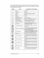
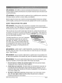
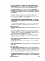
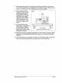
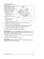
5=1/2OinoOircuSar Saw
Model No. 320°28191
_k CAUTION! Read, understand
and
follow aH Safety Rules and Operating
gnstructions in this Manual before
using this product.
Sears, Roebuck
www.craftsrnan,com
and Coo, Heffman Estates,
o
o
°
°
Warranty
Safety
Operation
Manntenance
IL 60&79
Warranty
Page 2
Safety Symbols
Page 3-4
Safety Instructions
Page 5-12
Glossary of Woodworking
Terms
Page 13
Know Your Circular Saw
Page 14-15
Page 15-16
.Unpacking
Operation
Pages
Maintenance
Pages 24 - 25
Parts List and Exploded
View
ONE YEAR FULL WARRANTY
16 - 23
Pages 26 - 29
ON CRAFTSMAN@
PRODUCT
tf this Craftsman tool fails to give complete satisfaction within one year
from the date of purchase, return it to any Sears store or other Craftsman
outlet in the United States for free replacement.
This warranty does not include parts, such as saw blades,that
out from normal use within the warranty period.
can wear
This warranty applies for only 90 days from the date of purchase
product is ever used for commercial or rental purposes.
if this
This warranty gives you specific legal rights, and you may also have other
rights, which vary from state to state.
Sears, Roebuck
and Coo, Hoffman
Estates, 1L 60179
,&
WARNING: Some dust created by using power tools contains chemicals
known to the state of California to cause cancer and birth defects or other
reproductive
harm.
SAVE THESE
iNSTRUCTiONS!
READ ALL BNSTRUCTIONS!
28191
ManuaLRevised
07-0202
Page 2
The purpose
of safety symbols
safety symbols,
understanding°
The symbol
ger. The instructions
prevention
with them, deserve
warnings
and warnings
dangers.
The
your careful attention
to possible
and
DO NOT by themselves
eliminate
they give are no substitutes
any dan-
for proper
accident
measures°
WARNING:
BE SURE to read and understand
as "DANGER,"
to follow
is to attract your attention
and the explanations
"WARNING,"
all instructions
and "CAUTION"
all safety alert symbols
BEFORE
may result in electric
shock,
using
such
this product.
fire, and!or
serious
Failure
personal
injury.
SYMBOL
_k
MEANINGS
SAFETY
ALERT
SYMBOL:
May be used in conjunction
DANGER:
DANGER,
with other symbols
or to others.
shock
Always
and personal
follow
WARNING,
OR CAUTION°
or pictographs..
Failure to obey this safety warning
injury to yourself
of fire, electric
Indicates
WILL
result in death or serious
the safety precautions
to reduce
the risk
injury.
WARNING; Failure to obey this safety warning CAN result in death or serious
injury to yourself or to others. Always follow the safety precautions to reduce the risk
of fire, electric shock and personal injury,
CAUTION:
Failure to obey this safety warning MAY result in personal injury
to yourself or others or property damage. Always follow the safety precautions to
reduce the risk of fire, electric shock and personal injury.
DAMAGE
PREVENTION
AND
INFORMATION
These inform the user of important
information
MESSAGES
and/or
instructions
to equipment
or other property damage if they are not followed°
preceded by the word "NOTE," as in the example below:
NOTE: Equipment
followed.
and!or
property
Z_
damage
WARNING:
that could lead
Each message
may result if these instructions
The operation
lar blade can result in foreign
goggles
objects
power tool operation,
or safety glasses
are not
of any tool with a circubeing thrown
your eyes, which can result in severe eye damage.
beginning
is
ALWAYS
with side shield
shield when needed_ We recommend
into
Before
wear safety
and a full-face
a Wide Vision Safety
Mask for use over eyeglasses or standard safety glasses
with side shield, available at Sears Stores or other Craftsman Outlets.
28191 ManuaLRevised_07_0202
Page 3
Some of these following
learn their meaning,
symbols
may be used on this tool. Please study them and
Proper interpretation
of these symbols
will allow you to operate
the tool better and more safely°
SYMBOL
NAME
DESIGNATION
v
Volts
Vottage
A
Amperes
Current
Hertz
Frequency(cycles
Hz
w
....
Watt
min
Alternating
Time
Current
Type of current
Direct Current
Type or a characteristic
•
no
,
•
No Load Speed
[]
Rotational
Class II Construction
Per Minute
Wet Conditions
.....
of current
,.,
.........
=
speed, at no load
Double-insulated
!
•
=
.....
imin
per second) ....
r Power
Minutes
'%,
/ EXPLANATION
construction
................................
Revolutions, strokes, surface speed,
orbits, etc., per minute
Alert
Do not expose to rain or use in damp
locations°
O
Read the Product Manual
read
and understand
productuser
manual
To reduce
the risk of injury,
must
before using this product,,
Q
Eye Protection
glasses
with side
andora safety
full-face
Always wear
safetyshields
goggles
shield when operating this product.
Safety Alert
__
.............. .,.
......
. ,,,
.....
No Hands Symbol
.
@
®
28191
Precautions
.... =
,
that involve your safety.
....
Failure to keep your hands away from
the blade will result in serious personal
injury.
No Hands Symbol
Failure to keep your hands away from
the blade will result in serious personal
injury,.
No Hands Symbol
Failure to keep your hands away from
the blade wilt result in serious personal
injury.
No Hands Symbol
Failure to keep your hands away from
the blade will result in serious personal
in jury,.
Hot Surface
To reduce the risk of injury or damage,
avoid contact with any hot surface.
Manual Revised 07_0202
Page 4
_k
WARNING:
manual.
Failure to follow
ous personal
Z_
BE SURE to read and understand
Before
All repairs
should
Center
to ensure
Service
using the circular
and thoroughly,
SAFETY
may result in electric
in this product
shock, fire and/or
seri-
injury.
WARNING:
at a Sears
all instructions
all instructions
be performed
saw, read the accompanying
and keep all of the documents
PRECAUTIONS
WARNING:
by a qualified
FOR
service
technician
safety and reliability.
Safety
supplied
Instructions
carefully
with the tool in a safe place°
LASERS
Always follow the instructions
contained
in this manual when
using the laser. Use of this feature in any manner other than that which appears in
this manual may result in a hazardous radiation exposure,.
This circular
put power
saw has a built-in
of a maximum
laser light. The laser is a Class
2.5mW
not normally present an optical
this can cause flash blindness°
and 635_665nm
hazard.
ilta and emits out-
wavelengths.
However,
These lasers do
DO NOT stare at the beam as
The label opposite
is on your tool. It indicates
the location from which the saw emits the
laser light, BE AWARE
tion when
using,
any bystanders
MAKE SURE that
in the vicinity
aware of the dangers
the laser°
_k
of the laser light loca-
ALWAYS
WARNING:
of use are made
of looking
LASER
directly
LIGHT. LASER
into
RADIATION.
DO NOT stare into beam_ Only turn laser beam
piece.
Class
Avoid
Direct
Eye Exposure.
on when the saw is on the work-
ltla laser.
WARNING:
Use of controls, adjustments
or performance
of procedures
oth-
er than those specified in this manual may result in hazardous radiation exposure.
WARNING:
The use of optical instruments
such as, but not limited to, tele-
scopes or transits to view the laser beam will increase eye hazard.
1.
13o not remove
increases
2.
Avoid
3.
any product
the risk of exposure
direct
look directly
project
or deface
eye exposure,
The laser beam
directly
The laser
on the saw is not a toy, Always
labels
to eyes Do not
operation.
Do not
Turn the laser on
cuts.
dren. The laser light emitted
28191 Manual Revised_07-0202
during
into the eyes of bystanders.
making
any person
product
can be harmful
aperture
only when
towards
Removing
to laser radiation.
into the laser-beam-output
the laser beam
labels,
from
this device
keep it out of the reach of chilshould
never
be directed
for any reason.
Page 5
P
Be sure
the laser beam
reflective
faces
surface,
can reflect
is aimed
such as wood
surfaces.
aware
piece that
such as sheet steel that
The shiny surface
could
that laser light reflected
reflect
does
surface.
the laser light into your eyes, causing
Do not use on surfaces
5_
at a work
or a rough-coated
sur-
flash blindness
have
shiny,
the beam back
off a mirror
not have a
Reflective
or any other
reflective
at the operator.
reflective
surface
Be
can
be dangerous,
Always turn the laser beam off when not in use. Leaving the tool on increases the risk of someone inadvertently staring into the laser beam.
6_
Do not attempt
to modify
result in a dangerous
exposure
Use only accessories
8_
the performance
of this laser
device.
This may
to laser radiation°
that are recommended
cessories
that have been designed
in serious
injury.
by Sears.
for use with other
Use of other ac-
laser tools
could
result
For further information regarding lasers, refer to ANSI-Z136.1, the standard for the
safe use of lasers, available from the Laser Institute of America (407) 380-1553,
g,
WORK
1.
AREA
SAFETY
Keep the work
accident&
area clean
and well tit. Cluttered
Don't use in a dangerous
locations
or expose
mospheres,
Operate
the tool
Dust generated
collection
power
of flammable
and dark areas invite
tools in damp
tools in explosive
liquids,
or wet
at-
gases or dust. Power
may ignite the dust or fumes.
in wellwentilated
areas, and provide
from some materials
Keep children
4.
which
systems
Don't use power
them to rain. Do not operate
such as in the presence
tools create sparks
37
environment,
benches
whenever
can be hazardous
proper dust removal.
to your health° Use dust-
possible°
and bystanders
away while operating a power
toot. Distractions
cause you to lose control.
,
Use the right
tool.
Don't force a tool or attachment
to do a job for which it was
not designed.
.
Make
starter
the workshop
ELECTRICAL
1.
kid-proof
with padlocks,
master
switches,
SAFETY
Do not change
the plug in any way. This circular
Double insulated
tools are equipped
saw is a double-insulated
with a polarized
the other.) This plug will fit in a polarized
trician to install a polarized
Double
insulation[_eliminates
and grounded
tools.
28191
plug (one blade is wider than
a qualified
elec-
outlet. Do not change the plug in any way.
the need for the three-wire
power supply system. Applicable
Manual_Revised 0743202
too!,
outlet only one way. If the plug does not
fit fully in the outlet, reverse the plug. If it still does not fit, contact
2.
or by removing
keys°
grounded
power cord
only to Class II (double insulated)
Page 6
3.
ALWAYS
tors,
avoid
ranges
body
contact
with grounded
and refrigerators.
surfaces,
such
as pipes, radia-
There is an increased risk of electric
shock
if
your body is grounded
4o
,
Do not expose power tools to rain or wet conditions.
tool will increase the risk of electric shock.
7o
a power
When operating
a power tool outside, ALWAYS use an outdoor extension
cord marked
"W-A" or "W". These cords are rated for outdoor use and reduce
the risk of electric
.
VVater entering
shock°
Do not abuse the cord, Never use the cord to carry the tools or to pull the
plug from the outlet. Keep the cord away from heat, oil, sharp edges, or moving
part& Replace damaged cords immediately. Damaged cords increase the risk of
electric shock.
Use the proper
extension
cord.
o Make sure that your extension cord is in good condition.,
o When using an extension
current your product
voltage,
resulting
cord, be sure to use one heaw
wilt draw, An undersized
in loss of power
enough to carry the
cord wilt cause a drop in line
and overheating,,
,, Table A shows the correct size to use, depending on cord length and ampere
rating. If in doubt, use the next heavier gauge: the smaller the gauge number,
the heavier the cord°
o When operating a power tool outdoors, ALWAYS use an outdoor extension
cord marked "W-A" or "W.," These cords are rated for outdoor use and reduce
the risk of electric shock.
Minimum Gauge for Extension Cords
Volts
120V
- Ampere Rating
More than 0
Not more than 6
More than 6
Not more than 10
More than 10
Not more than 12
0-25ft.
AWG
Total Lenghth of Cord in Feet
25-50ft.
51-100fti .....10i-150ff.
AWG
AWG
AWG
16
16
16
14
16
16
I6
16
.14
14
12
12
I ......
More than 12
Not more than 16
PERSONAL
14
I2
Not Recommended
SAFETY
WARNING:
Use of this tool can generate
dust containing
chemicals
known to the state of California to cause cancer, birth defects, or other
reproductive harm. Some examples of these chemicals are:
o
Lead from lead-based
o
Crystalline
paints.
silica from bricks, cement,
28191 Manual Revised 0743202
and other masonry
products,
Page 7
o
Arsenic
and chromium
from chemically
treated
lumber.
Your risk from these exposures varies, depending upon how often you do this
type of work. To reduce your exposure to these chemicals:
=
Work in a well-ventilated
area.
o
Work with approved safety equipment, such as those dust masks that are
specially designed to filter out microscopic
particles.
Avoid prolonged contact with dust from power sanding, sawing, grinding,
drilling, and other construction
activities. Wear protective clothing and wash
exposed areas with soap and water.
Allowing dust to get into your mouth or eyes or to tie on the skin may promote
absorption of harmful chemicals.
WARNING:
ing thrown
The operation
into your eyes, which
ning power-toot
shields,
Mask
of any power
operation,
and a full face shield
eye protection
which
can result in severe
always
wear safety
when
for use over eyeglasses
needed.
or standard
is marked
tool can result in foreign
or safety
We recommend
safety
to comply
eye damage.
goggles
glasses
objects
Before
glasses
be-
beginwith side
Wide Vision Safety
with shields.
Always
use
with ANSI Z87.1
Stay alert, watch what you are doing and use common sense when operating a power tool, Do not use a power tool while you are tired or under
the influence of drugs, alcohol or medication. A moment of inattention while
operating power tools may result in serious personal injury.
In
Dress
2_
properly.
and gloves
caught
Do not wear loose clothing
away from moving
in moving
Avoid accidental
3_
plugging
power
4o Remove
starting,
adjusting
.
control
Use safety
.
8.
Wear
USE
Always
non-skid
footing
safety
wear
shoes,
will reduce
protection
AND
WARNING:
tool may create
or tong hair can be
CARE
28191 Manua! Revised 07-0202
on the switch
before
or plugging
the tool on. A wrench
at all times.
or a
injury.
This enables
situations.
eye protection.
Safety
hard hat or hearing
personal
in
accidents.
and balance
to help prevent
equipment
protection
such
used for
injurie&
hearing
loss.
plug while inserting
it into or removing
it
SAFETY
Use of accessories
hazardous
is in the off position
before turning
toot in unexpected
Never touch the pins of the electrical
from an electrical socket.
TOOL
_k
Keep proper
conditions
hearing
Keep your hair, clothing
jewelry
to a rotating part of the tool may result in personal
equipment.
appropriate
on invites
keys or switches
of the power
as dust masks,
or jewelry.
clothes,
tools with your finger
that have the switch
Do not overreach.
better
Ensure the switch
power
key that is left attached
5.
Loose
parts.
in. Carrying
tools
parts.
that are not recommended
for use with this
conditions.
Page 8
1_ Keep guards
2.
Avoid
accidental
plugging
3.
4_
starting.
Do not carry
tools
Use clamps
unstable
with your
or another
platform.
before
outlet.
finger
practical
Holding
is in the "Off" position
on the switch.
way to secure
and support
the work by hand or against
the workpiece
your body leaves it
and may lead to loss of control.
Do not over reach.
6_ Do not force
correct
order,
Be sure the switch
the tool into an electrical
to a stable
54
in place and in working
Keep proper
the tool.
footing
Use the correct
and balance
at al! times_
tool and blade for your application.
tool and blade will do the job better and more safely when
The
used at the
rate for which it is designed_
7.
Do not use tool
cannot
8.
be controlled
Disconnect
the power
storing
power
Store
does
not turn it "ON"
with the switch
the plug from
tool
the power
9.
if the switch
before
is dangerous
the power
making
tools. Such
source
Any toot that
and must be repaired.
and/or
any adjustments,
preventive
or "OFF,"
the batter
changing
safety measures
pack from
accessories
reduce
or
the risk of starting
tool accidentally.
idle power
unfamiliar
tools
out of the reach of children
and do not allow persons
with the power tool or these instructions to operate the power
Power tools are dangerous
10o Do not allow persons
to operate
in the hands of untrained
unfamiliar
with the power
tool.
users.
tool
or these
instructions
this tool.
11o Never leave the tool r_Jnning unattended; turn the power off. Don't leave the
tool until it comes to a complete stop.
12. Always maintain tools with care. Keep cutting tools sharp and clean° Properly
maintained tools with sharp cutting edges are less likely to bind and are easier to
control° Follow all instructions for lubricating and changing accessories,
13. Check
for damaged
that is damaged
properly
parts,
should
and perform
binding
to determine
Check
mounting,
or other
accessories.
accessories.
that it will operate
for alignment
and any other
part that is damaged
of moving
conditions
should
that may
be properly
intended
the working
ManuaLRevised
The
Consult
use of improper
the product
manual
for recom-
accessories
may increase
the
injury.
15. Use the saw, blades,
28191
parts,
checked
function°
or replaced.
risk of personal
manner
be carefully
A guard
!4. Use recommended
mended
Before further use of the tool, a guard or other part
its intended
of moving
affect its operation.
repaired
parts.
etc. in accordance
for the saw, as described
conditions
0743202
with these
instructions
in this manual,
taking
and in the
into account
and the nature of the work to be performed.
Page 9
SERVICE
#
2_
SAFETY
If any part of this saw is missing or should break, bend, or fail in any way; or
should any electrical component fail to perform properly: ALWAYS shut off
the power switch and remove the plug from the power source, and have the
missing, damaged, or failed part replaced BEFORE resuming operation.
All ser,4ce that requires
Service
insulation
system
vice performed
3_
and MUST
only be serviced
by unqualified
SAFETY
DANGER!
second
personnel
be performed
only by a Sears
components
of the double-
by a Sears Service
Center. Ser-
could result in a risk of injury°
RULES
hand on the auxiliary
iNCH CIRCULAR
area and the blade.
handle or motor housing.
SAW
Keep your
If both hands are holding the
be cut by the saw.
1o Keep your body
positioned
line with the saw blade.
See'Kickback"o
Check
FOR THE 5-1/2
Keep hands away from cutting
saw, the cannot
2.
the tool MUST
parts are important
When servicing this tool, ALWAYS use only identical replacement parts. Follow
instructions in the Maintenance Section of this manual. Use of unauthorized
parts or failure to follow Maintenance Instructions may create a risk of electric
shock or injury.
SPECiFiC
_k
opening
Center° All of the motor
lower
to either
Kickback
guard for proper
side of the saw blade
could cause the saw to jump
closing
before each
baclqwards.
use, Do not operate
if lower guard does not move freely and close instantly,
lower guard into the open position.
and not in direct
saw
Never clamp or tie the
If saw is accidentally
dropped,
may be bent. Raise the lower blade guard with the retracting
lower guard
handle,
Make sure
it moves freely and does not touch the blade or any other part, in all angles and
3.
depths
of cut.
Check
the operation
are not operating
operate
debris.
4.
sluggishly
Hold the tool
of the lower
properly,
spring,
they must be serviced
due to damaged
by its insulated
tion where the cutting
guard
parts, gummy
gripping
tool may contact
surfaces
hidden
with a "live" wire will also make exposed
tf the guard and the spring
before
use, Lower guard may
deposits
or a buildup
when performing
wiring
of
an opera-
or its own cord. Contact
metal parts of the tool "live" and shock
the operator.
5.
Never
hold piece
workpiece
minimize
6.
Lower
"pocket
handle.
being
cut in your hands
to a stable platform.
body exposure,
guard
cut"
should
It is important
blade binding
be retracted
and "compound
cut."
28191 Manual_Re,,4sed_07_0202
your
to support
leg, Secure
the
the work properly
to
or loss of control.
manually
only for special
cuts such
as
Raise lower blade guard by retracting
As soon as blade enters the material,
For all other sawing,
or across
the lower guard should
the lower guard must be released.
operate
automatically.
Page 10
7o Do not reach underneath the workpiece.
the blade below the workpiece.
The guald cannot protect you from
Always observe that the lower guard is covering the blade before placing
the saw down on bench or floor. An unprotected, coasting blade will cause
the saw to walk backwards, cutting whatever is in its path. Be aware of the time
it takes for the blade to stop after switch is released.
8_
9.
Always
use a rip fence
the accuracy
I0
Always
use blades
of arbor
holes.
run erratically,
11, Never
or straight
of the cut and reduces
edge guide
when
the chance
of the blade binding,
with the correct
size and shape
Blades that do not match the mounting
causing
use damaged
and bolt were specially
ripping.
(diamond
This improves
versus
hardware
round)
of the saw will
loss of control,
or incorrect
designed
blade
washers
or bolt. The blade washers
for your saw for optimum
performance
and
safety of operation.
KICKBACK
Kickback is a sudden reaction to a pinched, bound or misaligned saw blade,
causing an uncontrolled
saw to lift up and out of the workpiece toward the
operator.
14
When the blade is pinched
or bound tightly by the kerf
closing down, the blade
stalls and the motor reaction drives the unit rapidly
back towards the operator
24
If the blade becomes
twisted or misaligned in the
cut, the teeth at the back
edge of the blade can dig
into the top surface of the
wood causing the blade
to climb out of the ked
and jump back toward the
operator.
3_
*
.
r
Fig. 1
Incorrect Support
support is too far from cut line
Kickback is the result of
misuse and/or incorrect operating procedures or conditions and can be avoided
by taking proper precautions, as given below:
Maintain a firm grip with both hands on the saw and position your arms to resist
kickback forces. Position your body to either side of the blade, but not in line
with the blade. Kickback could cause the saw to jump backwards, but kickback
forces can be controlled by the operator, if proper precautions are taken.
When blade is binding or when interrupting
a cut for any reason, release the
trigger and hold the saw motionless
in the material until the blade comes to a
complete stop. Never attempt to remove the saw from the work or pull the saw
backward while the blade is in motion or kickback may occur. Investigate and
take corrective actions to eliminate the cause of blade binding.
28191
Manual
Revised 07©202
Page 11
When restarting a saw in the workpiece,
center the saw blade in the kerf and
check that saw teeth are not engaged into the material,. If saw is binding, it may
walk up or kickback from the workpiece as the saw is restarted.
7_
.
Support large panels to
minimize the risk of blade
Fig. 2
pinching and kickback,
Large panels tend to sag
under their own weight.
Supports
must be placed
under the panel on both
sides, near the line of cut
and near the edge of the
panel.
Do not use dull or dam-
g_
aged blades. Unsharpened
or improperly
set blades
produce narrow kerf causing excessive friction, blade
binding and kickback.
Correct Sup'port
.....
_j
I
support is close enough to cut line
10. Blade depth and bevel adjusting locking levers must be tight and secure before
making cut. if blade adjustment shifts while cutting, it may cause binding and
kickback.
11. Use extra caution when making a "pocket cut" into existing walls or other blind
areas° The protruding blade may cut objects that can cause kickback.
28191
Mammal Revised_07-0202
Page 12
Arbor: The shaft on which the cutting tool is mounted. Bevel Cut: A cutting operation made with the blade at any angle other than 90 ° to the plane of the workpiece.
Chamfer
Cut: A cut removing a wedge from a block of wood so that the end (or
portion of the end) is angled other than 90°°
Compound
Cross
Miter
CUt: A cut with both a bevel angle and a miter angle.
Cut; A cutting
or shaping
operation
made against the grain of the workpiece.
Dado Cut; A non-through
cut that produces
workpiece
(requires a special blade),,
Gum: A sticky, sap-based
a square-sided
notch or trough
in the
residue from hardwoods.
Kerr: The material removed by the blade in a through
the blade in a non-through
cut or partial cut°
cut, or the slot produced
by
Kickback: A hazard that can occur when the blade binds or stalls, throwing the
workpiece back towards the operator°
Miter CUt: A cutting operation made with the blade at any angle other than 90 ° to
the fence.
Non-Through
Cuts: Any cutting operation where the blade does not extend completely through the thickness of the workpiece, such as a dado cut.
Resin: A sticky, sap-based substance that has hardened.
Revolutions
per Minute
object in one minute.
(RPM)" The number
of turns completed
by a spinning
Ripping or Rip Cut; A cutting operation along the length of the workpiece.
Saw-Blade Path: The area over, under, behind, or in front of the blade, as it applies
to the workpiece, or the area that will be or has been cut by the blade.
Set: The distance that the saw-blade tooth is bent (or set) outward from the face of
the blade.
Spindle: The shaft on which the cutting tool is mounted. Also called the Arbor.
Through Sawing: Any cutting operation where the blade extends completely
through the thickness of the workpiece.
28191 Mar_uaLRevised_07©202
Page 13
Fig. 3
Laser Switch
Spindle Lock Button
Upper Blade Guard
Worldight
Lower Blade Guard
lever
Edge Guide Lock
Knob
Blade
Bevel-Adjustment
Knob
Blade Screw
Bevel Scale
Lower Blade Guard
45 ° Blade Guide
Notch
Edge Guide
0 ° Blade Guide
Notch
Handle
Trigger Switch
Depth*of-Cut
Adjustment
Lever
Base
PRODUCT
SPECIFICATIONS
Input
8 Amps
Rating
120V, 60Hz AC
No load Speed
4000RPM
Blade Diameter
5 1/2 in,, (140ram)
Cutting Depth at 90 °
t 5!8 in, (41 mm)
Cutting Depth at 45 °
1 1/16 in. (27mm)
Bevel
Adjustable 0 ° - 480
Laser beam
Classe Ilia 635-665nm
28191 ManuaLRevised_OTO202
max° outputs< 2.SmW
Page 14
WARNING: The safe use of this product requires an understanding of the
information on the tool and in this product manual, as well as knowledge of the
project you are attempting° Before use of this product, familiarize yourself with all
operating features and safety rules.
0 ° TO 48 ° Bevel
Adjustment
The bevel-adjustment
48°
LASERTRAC
TM
lever allows you to set the trim saw for bevel cuts from 0 ° to
Laser Guide
The laser guide projects
and accuracy.
a bright
red line onto the workpiece,
aiding in alignment
LED Worklight
The fixed-position
line visibility.
LED worklight,
located
on the front of the saw, allows
better cut-
Edge Guide
The saw is equipped
Spindle-Lock
with an edge guide for accurate
parallel cuts.
Button
The spindle-lock
screw.
Depth-of-Cut
button
allows you to secure the blade when turning
Adjustment
Lever
The depth-of-cut
adjustment
lever adjusts the depth
1 5i8qn. at 90 ° and 0 to 1 1/164n. at 45 °.
WARNING:
If any parts are broken
or missing,
of cut a maximum
DO NOT attempt
the power cord or operate the saw until the broken or missing
Failure to do so could result in possible serious injury.
Z_
WARNING:
recommended
Do not attempt
injury, always
to modify
To prevent
disconnect
condition
accidental
of 0 to
to plug in
parts are replaced.
this saw or create accessories
for use with this saw° Any such alteration
and could result in a hazardous
WARNING:
the blade
or modification
leading to possible
starting
that could
serious
is misuse
injury.
cause serious
the tool from the power source when
not
assembling
personal
parts.
UNPACKING
This product has been shipped completely assembled.
1. Carefully remove the too! and the accessories from the box. Make sure that all
items listed in the packing list are included.
2.
Inspect the tool carefully to make sure that no breakage or damage occurred
during shipping.
28191
ManuaLRevised_07©202
Page 15
3_
4.
Do not discard the packing material until you have carefully inspected and satisfactorily operated the too!.
if any parts are damaged or missing, please contact the nearest service center.
PACKING
LiST
5 1/24n_ Trim Saw, Saw Blade, Edge Guide, Hex Key, Glasses, Carbon Brush and
Product Manual
SAW BLADES
The best of saw blades
sharp, and properly set.
and increase the danger
sharp blades are always
will not cut efficiently if they are not kept clean,
Using a dull blade will place a heavy load on the saw
of kickback. Keep extra blades on hand, so that
available°
Gum and wood pitch that have hardened on the blades will slow the saw
down. Use gum and pitch remover, hot water, or kerosene to remove these
accumulations.
DO NOT USE GASOLINE.
BLADE
GUARD
SYSTEM
The lower blade guard attached to your saw is there for your protection and
safety, it should never be altered for any reason. If it becomes damaged or
begins to return to position slowly, do not operate the saw until the damage
has been repaired or the blade guard has been replaced. Always leave the
blade guard in the operating position when using the saw.
,_
DANGER:
When sawing through
a workpiece,
the lower blade guard
does not cover the blade on the underside of the workpiece. Keep hands and
fingers away from the cutting area. If any part of your body comes in contact
with the moving blade, serious injury will result.
CAUTnON: Never use the saw when the guard is not operating correctly.
Check the guard for correct operation before each use. The guard is operating correctly when it moves freely, and readily returns to the closed position.
If you drop the saw, check the lower blade guard and bumper for damage at
all depth-of-cut
settings before reuse.
28191 Manual
Revised_0743202
Page 16
STARTING/STOPPIING
SAW (Fig. 4)
THE
Fig° 4
To start the saw: Depress the
trigger switch. Always allow
the blade to reach full speed,
then guide the saw into the
workpiece.
Trigger Switch
To stop the saw: Release
the trigger switch. After you
release the trigger switch,
allow the blade to come to
a complete stop_ Do not
remove the saw from the
workpiece
moving,
while the blade is
DEPTH-OF-CUT
ADJUST-
Fig. 5
NIENT (Fig. 5)
Depth Indicator
Always keep the correct depthof-cut setting. The correct
depth-of-cut setting should
not exceed 1/4 inch below the
material to be cut. Only one
saw-blade tooth should show
beneath the material. If more
than one blade tooth shows,
Depth Scale
then the depth of cut is too
deep. Excessive depth of cut
will increase the chance of
kickback and cause the cut to
be rough.
TO ADJUST
DEPTH
Depth-of_Cut
Adjustment
Lever
OF CUT
o
Disconnect the saw from the power source.
,,
Loosen the depth-of-cut
o
Place the base flat on the workpiece, and raise or lower the saw until the depthof-cut indicator aligns with the desired depth on the scale.
o
Securely tighten the depth-of-cut
adjustment lever°
adjustment lever_
NOTE: Make a trial cut on a piece of scrap material to ensure that the laser is
aligned properly.
28191 Manual
Revised_07-0202
Page 17
USUNG THE LASER TRAC
TM
LASER GUIDE (Fig. 6)
I Fig. 6
,_ WARNING: !_ASER
LIGHT, LASER RADIATION.
Laser Switch
Avoid Direct Eye Exposure, DO
NOT stare into beam. Only turn
laser beam on when the saw
is on the workpiece, The laser
is factory installed and aligned,
Class !lla laser.
To operate
1.
the laser
guide:
Disconnect the saw from
the power source.
2.
Mark the line to be cut on the workpiece_
3o Adjust the depth and angle of the cut as needed.
4.
Plug the saw into an electrical outlet.
5. Slide the Laser switch forward to turn the laser on.
6. Start the saw.
7, Align the laser beam with the cut line, and slowly push the saw forward into the
workpiece.
&
Once the cut is complete, release the trigger switch, and allow the saw to come
to a complete stop.
9. Always turn laser beam off when you have finished cutting.
NOTE:
Do not touch the blade to the workpiece
until the saw has reached
maxi-
mum speed
NOTE: Make a trial cut on a piece of scrap material to ensure that the laser is
aligned properly.
USING
THE LED WORKLeGHT
The saw is equipped with a fixed-position worklight for better visibility when cutting_
It will be lighted for illuminating the cutting area as soon as you plug in the saw.
28191 ManuaLRevised
07-0202
Page 18
OPERATING
THE SAW
tt is important to understand the correct method for operating the sawn Refer to the
instructions in this section to learn the correct and incorrect ways for handling the
saw.
,_k DANGER: When lifting the saw from the workpiece, the blade is exposed on
the underside of the saw until the lower blade guard closes_ Make sure the lower
blade guard is closed before setting the saw down.
,_k DANGER: To make sawing easier and safer, always maintain proper control of
the saw.. Loss of control could cause an accident resulting in possible serious injury.
To make the best possible
•
cut:
Hold the saw firmly with
hand.
Fig. 7
Avoid placing your hand on
the workpiece while making
a cut.
Support the workpiece so
that the cut (kerr) is always
to your side.
O
"
Support the workpiece near
the cut°
Clamp the workpiece
securely, so that the workpiece will not move during
the cut.
o
Always place the saw on
the workpiece that is supported, not the "cut off"
piece.
Fig. 8
Place the workpiece with
the "good" side down.
Draw a guideline along the
desired line of cut before
beginning
your cut.
Wrong
NOTE: The "good" side of the
workpiece is the side where
appearance is important.
WARNING:
If the blade comes in contact with the workpiece before it reaches
full speed, it could cause the saw to "kickback"
serious injury.
28191
Manual_Revised O7-0202
towards you, which could result in
Page 19
,_
WARNING:
ALWAYS
securely
clamp
and support
the workpiece.
maintain proper control of the saw. Failure to clamp and support
and loss of control of saw could result in serious injury°
MAKING
CROSS
RIP CUTS
CUTS
ALWAYS
the workpiece
AND
(Fig. 9)
Fig. 9
When making a cross cut or
rip cut, align your cut line with
the notch marked 0 ° on the
saw base° Since
nesses
va_,
blade thick-
always
make
a trial cut in scrap material
along a guideline to determine
how much,
if any, the guide-
line must be offset to produce
an accurate cuL
Crosscut
ruler
A ruler for measuring cross
cuts is marked along the front of the saw base.
MAKllNG
RiP CUTS
Always use a guide when making long or wide rip cuts with your saw, You can
use either a straight edge or use the edge guide that was included with the saw,
1.
Securethe
2.
Clamp a straight edge to the workpiece
3.
Carefully guide the saw along the straight edge to achieve a straight rip cut,
EDGE
GUIDE
The saw comes
guide.
workpiece.
using C-clamps.
Fig_ 10
with an edge
It allows you to make ac-
curate parallel cuts when trimming
guide
a workpiece.
attaches
The edge
to the saw
base and is secured in place
with a turn screw. The arm of
the edge guide is stamped
with a scale from 0 to 9 inches
in 1/8-inch
ily adjusting
increments
for eas-
your cut.
Using the edge guide (Fig. 10)
Always use a guide when
making long or wide rip cuts with your saw. You can use either a straight edge or
use the edge guide that was included with the saw.
28191
Manuat Revised_07-0202
Page 20
WARNING:
Always
bling parts, changing
could cause serious
1.
Disconnect
2,
Position
disconnect
blades, and making
personal
Adjust
adjustments,
source when assem-
Failure to obey this warning
injury.
the saw from the power source.
the edge guide so that the ruler side of the arm is facing up. Slide the
arm of the edge guide through
3.
the saw from the power
the mounting
the edge guide to the desired
4. Tighten the edge-guide
slots at the front of the saw base,
width
of cut,
lock knob.
When using the edge guide, position the face of the edge guide firmly against the
edge of the workpiece. This wilt help make a true cut without binding the blade.
The edge of the workpiece must be straight for the cut to be straighL Use caution to prevent the blade from binding in the cut°
BEVEL
CUTTING
The cutting
angle can be adjusted
blade thicknesses
vary and different
make a trial cut in scrap
should
_k
the bevel
WARNING:
Always
cause serious
1.
Disconnect
2.
Loosen
3.
4.
.
disconnect
different
settings,
to determine
always
how much
you
to be cut,
adjustments.
source when assem-
Failure to obey this warning
injury°
the saw from
Raise the motor-housing
the power
knob
source.
by rotating
the knob
counterclockwise.
side of the saw until the bevel indicator
setting
Tighten
the bevel-adjustment
reaches
the
on the bevel scale (0 °- 48°)°
cut (Fig.11)
Secure the workpiece
clamps.
0 ° and 48°_ Since
the saw from the power
blade and making
personal
the bevel-adjustment
a bevel
require
along a guideline
on the workpiece
desired
Making
angles
between
setting
bling parts, changing
could
material
offset the guideline
To adjust
to any setting
knob
by rotating
the knob
clockwise.
Fig. 11
with
When making
a
bevel cut, hold the saw
firmly.,
2_
Rest the front edge of the
base on the workpiece.
Squeeze the trigger switch
to start the saw, Allow the
saw to reach full speed
before attempting
a cut.
28191 ManuaLRevised_07-0202
to make
Page 21
3_
After completing
to a complete
the cut, release the trigger switch
stop. After the blade has stopped,
and allow the blade to come
remove the saw from the work-
piece,,
For making 45 ° bevel cuts,
there is a notch in the saw
Fig. 1 la
Une of cut
base to help you line up the
blade with the cutting
Align your cutting
notch
marked
line.
line with the
45 °. (Fig° 11 a)
t_j.
- 45° indicator
,_ WARNING; Attempting
bevel cut without the beveLadjustment knob securely
tightened can result in serious
injury.
O°Bevei
stop
The saw has a 0°bevel stop that has been factory adjusted to assure a 0°angle of
the saw blade when making 90°cuts.
To check
0 ° bevel stop
_k WARNING;
(Fig. 12)
Always disconnect the saw from the power source when assem-
bling parts, changing the blade and making adjustments° Failure to obey this warning could cause serious personal injury.
I.
Disconnect
the saw from the power source.
2o Place the saw in an upside-down
3.
Using a carpenter's
the saw,
To adjust
1.
0 ° bevel
Disconnect
the power
position on a workbench.
square, check that the saw blade is square to the base of
stop
(Fig, 12)
the saw from
source.
Fig. t2
"_
2.
Loosen the bevel-adjustment knob.
3.
Place the saw in an upside-down position on a
workbench.
4_
Using
0°
bevel_stop
adjustment
screw
a hex key, turn the
0°bevel-stop
adjusting
screw until it is square
the saw blade.
28191 ManuaLRevised
07-0202
with
Bevel adjustment
knob
Page 22
POCKET
z_
CUTTING
WARNING;
the bevel
making
(Fig, 13)
Always
adjust
setting
to 0 ° before
a pocket
cut. Attempt-
ing a pocket
can result
control
of the saw, possibly
1,
Lower blade
guard lever
cut at any other
setting
causing
Fig° t 3
serious
in loss of
/
injury°
Disconnect
the saw from
the power source.
2,
3_
Adjust the bevel setting to
zero°
Set the blade to the correct depth of cut,,
4.
Plug the saw into a power
5.
Swing
6.
Hold the lower
7.
Rest the front
of the base flat against
the workpiece
handle
so that the blade does
not touch
the lower
raised,
blade
source.
guard
blade guard
up using the lower
Start the saw and allow the blade to reach
9.
Guide the saw into the workpiece,
,_
WARNING:
cut in a forward
ting in the reverse direction
back toward
you, possibly
t 0o Release
the trigger
11. Lift the saw from
!2. Clear corners
WARNING;
blade exposed
28191
with the rear of the
the workpiece.
full speed°
and make the cut.
direction
when making
could cause the saw to climb
causing
switch
serious
a pocket
cut. Cut-
up on the workpiece
and
injury.
and allow the blade to come
to a complete
stop,
the workpiece.
out with a hand saw or sabre saw.
Never tie the lower blade guard in a raised
could
ManuaLRevised
lever°
by the lever°
8.
Always
blade guard
position.
Leaving
the
lead to serious injury.
07-O202
Page 23
,_k WARNING: To ensure safety and reliability, all repairs should be performed by
a qualified service technician at a Sears Service Center.
_k WARNING:
To avoid serious personal injury, always disconnect the saw from
the power source when cleaning or performing any maintenance.
Power tools that are used to work on fiber-glass boats and sports cars, waltboard, spackling compounds, or plaster are subject to accelerated wear and
possible premature failure. The chips and grindings from these materials are
highly abrasive to electrical tool parts, such as bearings, brushes, commutators,
etc. Consequently, it is not recommended that this tool be used for extended
work on any fiberglass material, wallboard, spackling compound, or plaster. During any use on these materials, it is extremely important that the tool is cleaned
frequently by blowing with an air jet.
WARNING:
Always wear safety goggles or safety glasses with side shields
during power tool operation or when blowing dust, If operation is dusty, also wear a
dust mask°
GENERAL
MAINTENANCE
WARNING:
Do not at any time let brake fluids, gasoline, petroleum-based
products, penetrating oils, etc. come in contact with plastic parts. Chemicals can
damage, weaken or destroy plastic, which may result in serious personal injury.
Periodic maintenance allows for long life and trouble-free operation. A cleaning, lubrication, and maintenance schedule should be maintained. As a common preventive maintenance practice, follow these recommended steps:
When work has been completed,
of the tool over time.
clean the tool to allow smooth functioning
G
Use clean, damp cloths to wipe the tool.
9
Check the state of all electrical cables°
O
Keep the motor's
O
Store the tool
O
Be certain
lengthy
Avoid
clean
that al! exposed,
solvents
from
cloths
free from oil, grease, and sawdust
or woodchips.
in a dry placer
exposure
using
to damage
air openings
to damp
when
commercial
to remove
moving
and/or
cleaning
solvents
dirt, dust,
parts are welt lubricated,
particularly
after
dirty conditions.
plastic
parts.
Most
plastics
and may be damaged
oil, grease,
are susceptible
by their use. Use
etco
LUBRICATION
All of the bearings in this tool are lubricated with a sufficient amount of highgrade lubricant for the life of the tool under normal operating conditions.
Therefore, no further lubrTcation is required.
28191 ManuaLRevised_07©202
Page 24
CHANGING
THE BLADE
(Fig. 14)
A
WARNING:
A 5-1/2-in°
blade is the maximum
capacity
Fig, 14
Depth-of-cut
blade
adjustment lever
of the sawn Use only
5 1/2-in° blades when
/
replac-
ing worn or damaged blades.
Never use a blade so thick
that it does not allow the outer
blade washer to engage with
the flats on the spindle. Larger
blades will come in contact
Spindle
button
with the blade guard, while
thicker
blades will prevent
the
blade screw from securing
the blade on spindle. Either of
these situations could result in
a serious
,_
accident.
WARNING:
To prevent accidental
starting
that could cause serious
injury, always disconnect
the tool from the power
justments or changing accessories,
.
2,
.
4.
5.
Disconnect
8..
any ad-
source.
height,
Depress the spindle lock button, and place the hex key (supplied) in the
blade screw. Move the hex key back and forth until you feel the spindle lock
button depress further. This action locks the blade in position, so the blade
screw can be removed.
With the spindle lock button
wise to loosen the screw.
Raise the Io,_Jer blade guard,
Remove
firmly
depressed,
using the blade
turn the blade screw
guard
lever, and hold it in the
the blade
screw,
washer,
outer flange,
and the blade.
The remaining flange is the inner flange
does not need to be removed.
that fits around
Place a new saw blade inside
the lower
blade guard,
and against
washer.
Replace
10o Depress
28191 Manual
the inner bushing
of the blade
the outer flange
should
the screw
the blade screw
Revised 0743202
point
upward
the spindle
shaft;
onto the spindle
it
shaft
at the front the saw.
and washer_
and hold the spindle
hand tighten
tighten
clock-
position.
NOTE_ The teeth
9.
BEFORE making
Loosen the depth-of-cut
adjustment
lever. Raise the saw to maximum
and tighten the depth-of-cut
adjustment
lever°
raised
6.
the saw from the power
source
personal
lock button
in a counterclockwise
as you replace
direction°
the blade screw
and
Use the hex key to
securely.
Page 25
5_1/2-in. Circular Saw Model No. 320.28191 Always mention the Model Number
when ordering parts for this tool,,
01.
3550688000
Flange Bolt
1
02_
3520069000
Outer Flange
t
03,
3810376000
Blade
1
04.
3520070000
Inner Flange
1
05.
5660024000
Circlips For Shaft
1
Screw
3
,,,
06.
, ,,,......
_.................... ...,
,,,.....
5620039000
.......
,,,,
,,,,,
....
,,,,,....
07°
3123085000
Moving Guard Lever
1
08.
3420522000
Lower Guard
1
09.
3120593000
Bush
1
..,,,,,,
10.
3660081000
Spring
I
11.
3420520000
Upper Guard
1
..
,, ,,.........
12.
5610087000
Thread Forming Screw
13.
3420219000
Gear Case Cover
14.
5700015000
Ball Bearing
1
i5.
3700258000
Wave Washer
I
.........
t6o
*,*,,,,,,,,
......
,,,,,,,,
i
3700262000
,,,
, ,,,,
Wire Holder
.........................
,, ,,..............
t
,
, ,,,,,,,,_
....
17.
5660022000
Circlips For Hole
1
18.
3121384000
Lens
1
19.
2780039000
Laser Set
1
20.,
3420468000
Laser Holder
, , ,,, _ ...............
21,
i
3660069000
,,,,
Spring
-
22°
1
, ,,,_,,
1
,, ,,,, ,,,
5620089000
,,,,,,,,,
Slotted Set Screw
1
Plain Washer
2
,,, ,,
23.
565000'1000
...........
,......
24°
5650003000
Spring Washer
i
25.
5620006000
26.
3550774000
:
....
,,,
.....
,,,,,,
,,, ,,, ,,,,,,,,
,,,,,,,,
.....
2
,,,,, ....
Hexagon Socket Screw
2
Gear Shaft
2
,
27°
5680003000
Key
1
28.
5670008000
Spring Pin
1
29,
5610058000
Thread Forming Screw
1
, ,,,,,
3_3_3_01J
31!2105_1000
28191 ManuaLRevised
07-0202
Stopper
•...............
1
Page 26
31
3550231000
Gear
........
,,,,,,,,,,, ,
1
= ......
32
5700004000
Ball Bearing
1
33
5640155000
Bolt
2
34
3420519000
Gear Case
!
,,uu,,,,,
35
,
,.............
,,
3660076000
Spring
1
,,,,,,,,, ,,,,,
......
36
3402169000
Spindle Lock
1
37
5610061000
Thread Forming Screw
1
38
5610057000
Thread
2
57000'13000
Ball Bearing
1
40
5650053000
Washer
1
41
3402167000
"_
Forming
Screw
Lock Rod
...........
,,, ,,,,,, i
.......
42
2750843000
Rotor
1
43
3123086000
Depth Adjusting
44
5610042000
Tapping
3700315000
Dust Seal
1
Lever
10
Screw
1
,,,,,,,,,,, _
46
5700008000
47
3123089000
Fan Baffle
5610065000
Tapping
49
3700249000
Washer
50
3121049O0O
5'1
......
,,,,,,,,,, ,
.............
......
....
1
Ball Bearing
,,,,,,
,,
2
Rubber
Spring
1
5650015000
Spring
Washer
1
52
2740243000
Stator
2
53
3123091000
Lens
1
PCB Assembly
1
4890322000
.,_,_
,,,,,,,,,
Screw
'54
,__
1
55
3123084000
LED Cover
1
56
3123083000
Motor Housing
1
57
3'120537000
Brush Cover
2
,,,, ,,
,,, ,,,,,,,
....
58
4960019000
Carbon
Brush
2
59
2800O0500O
Brush Holder
2
60
5620016000
Hexagon
61
5610062000
Thread
62
3703720000
Rip Fence
.........
Socket
Forming
Screw
Screw
.,,,
2
3
,,,,,.......
63
342052t 000
,,,,, .....
64
28191
,,,j,,,,,,,
1
Base Plate
,
5620017000
ManuaLRevised_O743202
Hexagon
Socket
Screw
1
Page 27
65
3660071000
Spring
1
66
3400012000
Wing Bolt
1
67
3123087000
Bevel Lever
•
_6;
6;
70
--7it
5630197000
.......
, ,,,,,,,,,
1
.....
,,,,, ,,
=
.......
Square Nut
1
Rivet
2
;65001111701;0
........
5680012000
i3703686000
Support Plate
1
L,
72
3703687000
Depth Bracket
1
73
3320421000
Left Handle ASSY
1
74
3122922000
Laser Button
t
75
4930013000
Receptacle
2
76
4930012000
Terminal
2
77
2822246000
Transformer
78
3700285000
Cord Anchorage
1
79
5610031000
Thread Forming Screw
2
80
3121028000
Cord Guard
1
81
3402168000
Key
1
82
4810002000
Power cord
1
83
4930004000
Connecter
1
84
4870036000
Assy
1
,.,,.
Switch
.....
85
5620035000
•.
1
,,,,,,
.......
,,,, ......
Screw
4
, ,.,,,,,,,
86
3700540001
Sponge
3320422000
88
4860008000
114860008009
87
89
......
. ----
28191 ManuaLRevised
074)202
, i
,,,........
2
, ,,,,,,,,-,
......
• Right Handle ASSY
1
Inner Wire
2
Inner Wi_
2
Page 28
5-1/2-in.
Circular
28191 Manual_Revised
Saw Model
07-0202
No, 320.28191
Page 29
28191
Manual_Revised
07-0202
Page
30
28191
Manual
Revised_07_202
Page
31
Get it fixed, at your home or ours!
Your Home
For repair - in your home - of all major brand appliances,
lawn and garden equipment, or heating and cooling systems,
no matter who made it, no matter who sold it !
For the replacement parts, accessories
and
owner's manuals that you need to do-it-yourself.
For Sears professional
installation of home appliances
and items like garage door openers and water heaters.
1-800-4-MY-HOiVlE
®
(1-800-469-4663)
www.sears.com
Call anytime, day or night
(U,S.A and Canada)
www.sears.ca
For e_pert home solutions advice:' www.managemyhome.com
Our Home
For repair of carry-in products like vacuums, lawn equipment,
and electronics, call or go on-line for the nearest
Sears Parts & Repair Service Center
1-800-488-1222
(U S.A )
1-800-469-4663
(Canada)
Call anytime, day or night
www.sears.com
www.sears.ca
To purchase a protection agreement
1-800-827-6655
(us A)
Para pedir servicio de reparaci6n
a domicilio, y para ordenar piezas:
1-888-SU-HOGAR®
(1-888-7844427)
on a product serviced by Sears:
1-800-361-6665
(Canada)
Au Canada pour service en frangais:
1-800-LE-FOYER Mc
(1-80o-5334937)
www.sears ca
S ce /rs
© SearsBrands,HC
® Registered Trademark t TMTrademark t st_Service Mark of Sears Brands, LLC
® Marca Registrada 1TMMarca de F&brica / SMMarca de Servicio de Sears Brands, LLC
McMarque de commerce / MDMarque d6pos6e de Sears Brands, LLC