1
XQ125
XQ150
2001
5HT1-AE2
SERVICE MANUAL
EASM0000
XQ125 / XQ150
SERVICE MANUAL
© 2001 by MBK Industrie
2nd edition, April 2001
All rights reserved.
Any reproduction or unauthorized
use without the written
permission of MBK Industrie
is expressly prohibited.
EASM0001
NOTICE
This manual was produced by the MBK Industrie primarily for use by Yamaha and MBK dealers and
their qualified mechanics. It is not possible to include all the knowledge of a mechanic in one manual.
Therefore, anyone who uses this book to perform maintenance and repairs on Yamaha and MBK
vehicles should have a basic understanding of mechanics and the techniques to repair these types
of vehicles. Repair and maintenance work attempted by anyone without this knowledge is likely to
render the vehicle unsafe and unfit for use.
MBK Industrie is continually striving to improve all of its models. Modifications and significant changes in specifications or procedures will be forwarded to all authorized Yamaha and MBK dealers and
will appear in future editions of this manual where applicable.
NOTE:
Designs and specifications are subject to change without notice.
TECHNICAL DOCUMENTATION
MBK INDUSTRIE
EAS00005
IMPORTANT MANUAL INFORMATION
Particularly important information is distinguished in this manual by the following.
The Safety Alert Symbol means ATTENTION! BECOME ALERT! YOUR SAFETY
IS INVOLVED!
WARNING
Failure to follow WARNING instructions could result in severe injury or death to
the scooter operator, a bystander or a person checking or repairing the scooter.
CAUTION:
A CAUTION indicates special precautions that must be taken to avoid damage
to the scooter.
NOTE:
A NOTE provides key information to make procedures easier or clearer.
EAS00007
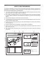
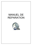
HOW TO USE THIS MANUAL
This manual is intended as a handy, easy-to-read reference book for the mechanic. Comprehensive
explanations of all installation, removal, disassembly, assembly, repair and check procedures are
laid out with the individual steps in sequential order.
햲 The manual is divided into chapters. An abbreviation and symbol in the upper right corner of each
page indicate the current chapter. Refer to "SYMBOLS".
햳 Each chapter is divided into sections. The current section title is shown at the top of each page,
except in Chapter 3 ("PERIODIC CHECKS AND ADJUSTMENTS"), where the sub-section title(s)
appears.
햴 Sub-section titles appear in smaller print than the section title.
햵 To help identify parts and clarify procedure steps, there are exploded diagrams at the start of each
removal and disassembly section.
햶 Numbers are given in the order of the jobs in the exploded diagram. A circled number indicates
a disassembly step.
햷 Symbols indicate parts to be lubricated or replaced. Refer to "SYMBOLS".
햸 A job instruction chart accompanies the exploded diagram, providing the order of jobs, names of
parts, notes in jobs, etc.
햹 Jobs requiring more information (such as special tools and technical data) are described
sequentially.
햳
햲
CYLINDER AND PISTON
햵
햴
ENG
CYLINDER AND PISTON
EASM0025
ENG
EAS00253
CYLINDER AND PISTON
햳
햷
햶
햲
햴
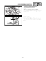
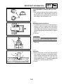
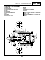
REMOVING THE CYLINDER AND PISTON
1. Remove:
• piston pin clip 햲
• piston pin 햳
• piston 햴
CAUTION:
Do not use a hammer to drive the piston pin
out.
NOTE:
• Before removing the piston pin clip, cover the
crankcase opening with a clean rag to prevent
the piston pin clip from falling into the crankcase.
• Before removing the piston pin, deburr the
piston pin clip’s groove and the piston’s pin
bore area. If both areas are deburred and the
piston pin is still difficult to remove, remove it
with the piston pin puller.
6
4
5
3
Piston pin puller
90890-01304
9
1
FW
햸
Order
1
2
3
4
5
6
7
8
9
10
11
T.R
10
11
8
7
2. Remove:
• top ring
• 2nd ring
• oil ring
12 Nm (1.2 m•kg)
NOTE:
When removing a piston ring, open the end gap
with your fingers and lift the other side of the ring
over the piston crown.
2
D
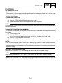
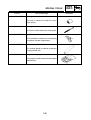
Job/Part
Q’ty
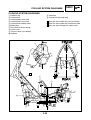
Removing the cylinder and piston
Cylinder head
Cylinder bolt
Timing chain guide (exhaust side)
Cylinder
Dowel pin
Cylinder gasket
Piston pin clip
Piston pin
Piston
Piston ring (top)
Piston ring (2nd)
Oil ring
Remarks
Remove the parts in the order listed.
Refer to “CYLINDER HEAD” section.
2
1
1
2
1
2
1
1
1
1
1
EAS00255
For installation, reverse the removal
procedure.
4 - 23
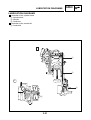
CHECKING THE CYLINDER AND PISTON
1. Check:
• piston wall
• cylinder wall
Vertical scratches → Rebore or replace the
cylinder, and replace the piston and piston
rings as a set.
4 - 24
햹
햲
EAS00008
햳
GEN
INFO
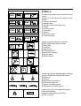
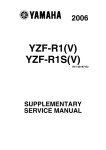
SYMBOLS
The following symbols are not relevant to every
vehicle.
Symbols 햲 to 햺 indicate the subject of each
chapter.
햲 General information
햳 Specifications
햴 Periodic checks and adjustments
햵 Engine
햶 Cooling system
햷 Carburetor
햸 Chassis
햹 Electrical system
햺 Troubleshooting
SPEC
햴
햵
CHK
ADJ
ENG
햶
햷
COOL
CARB
햸
햹
ELEC
CHAS
햺
Symbols 햻 to 헃 indicate the following.
햻 Serviceable with engine mounted
햽 Filling fluid
햾 Lubricant
햿 Special tool
헀 Tightening torque
헁 Wear limit, clearance
헂 Engine speed
헃 Electrical data
햻
TRBL
SHTG
햽
햾
햿
헀
T.
헁
헂
헃
헄
헅
헆
쎻
21
쎻
22
쎻
23
쎻
24
쎻
25
R
Symbols 헄 to 쎻
23 in the exploded diagrams indicate
the types of lubricants and lubrication points.
헄 Engine oil
헅 Gear oil
헆 Molybdenum disulfide oil
쎻
21 Wheel bearing grease
쎻
22 Lithium soap base grease
쎻
23 Molybdenum disulfide grease
Symbols 쎻
24 to 쎻
25 in the exploded diagrams
indicate the following.
쎻
24 Apply locking agent (LOCTITE®)
쎻
25 Use a new one
EAS00010
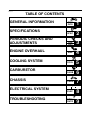
TABLE OF CONTENTS
GENERAL INFORMATION
GEN
INFO
1
SPEC
2
PERIODIC CHECKS AND
ADJUSTMENTS
CHK
ADJ
3
ENGINE OVERHAUL
ENG
4
COOL
5
CARB
6
CHAS
7
ELEC
8
TRBL
SHTG
9
SPECIFICATIONS
COOLING SYSTEM
CARBURETOR
CHASSIS
ELECTRICAL SYSTEM
TROUBLESHOOTING
GEN
INFO
1
GEN
INFO
CHAPTER 1.
GENERAL INFORMATION
SCOOTER IDENTIFICATION ........................................................................ 1-1
VEHICLE IDENTIFICATION NUMBER .................................................... 1-1
MODEL LABEL ........................................................................................ 1-1
FEATURES ................................................................................................... 1-2
OIL INDICATOR LIGHT ........................................................................... 1-2
ODOMETER/TRIPMETER READING MODE ......................................... 1-2
BATTERY VOLTAGE/FUEL GAUGE ...................................................... 1-2
THE CLOCK ............................................................................................. 1-3
AUTO-CHOKE SYSTEM ......................................................................... 1-3
IMPORTANT INFORMATION ......................................................................
PREPARATION FOR REMOVAL AND DISASSEMBLY ........................
REPLACEMENT PARTS ........................................................................
GASKETS, OIL SEALS AND O-RINGS ..................................................
LOCK WASHERS/PLATES AND COTTER PINS ...................................
BEARINGS AND OIL SEALS ..................................................................
CIRCLIPS ................................................................................................
1-4
1-4
1-4
1-4
1-5
1-5
1-5
CHECKING THE CONNECTIONS ............................................................... 1-6
SPECIAL TOOLS .......................................................................................... 1-7
SCOOTER IDENTIFICATION
GEN
INFO
EAS00015
GENERAL INFORMATION
햲
SCOOTER IDENTIFICATION
EASM0002
VEHICLE IDENTIFICATION NUMBER
The vehicle identification number 햲 is stamped
into the frame.
ZAUM0113
EASM0003
MODEL LABEL
The model label 햲 is affixed under the seat.
This information will be needed to order spare
parts.
햲
ZAUM0114
1-1
FEATURES
GEN
INFO
EASM0004
FEATURES
OIL INDICATOR LIGHT
• FUNCTION
Pulses (travel distance signals) from the speedometer are counted and cause the oil indicator light
to come on at 500 km for the first time and thereafter every 3,000 km. In this way, the light indicates
the time for oil change.
• RESETTING PROCEDURE
To reset the oil change indicator light
1) Press the “TRIP” button while turning the key to “ON”.
2) Release the button and the oil change indicator light will go off.
NOTE:
To reset the oil change indicator light before the periodic oil change interval has been reached, follow
the above procedure.
ODOMETER/TRIPMETER READING MODE
The odometer and tripmeter can be set to count in either miles or kilometers according to the following
procedure.
1) Turn the key to “ON”.
2) Press the “TRIP” button until the current mode appears in the dispaly:
“CONT” (continental) for kilometer mode and “EnGL” (English) for the mile mode.
3) Press the “TRIP” button to switch mode.
4) Press the “TRIP” button for two seconds to confirm the setting.
NOTE:
• The odometer/tripmeter reading mode can be changed any number of times while the odometer
reading is below 10, but it cannot changed anymore after the reading has reached 10.
• Switching between the mile and the kilometer mode does not change or convert the current odometer/
tripmeter reading.
BATTERY VOLTAGE/FUEL GAUGE
When the key is turned to “OFF”, the voltage/fuel gauge indicates the battery voltage.
NOTE:
If the battery voltage drops to 10V, refer to “CHECKING THE BATTERY” section in chapter 3.
When the key is turned to “ON”, the voltage/fuel gauge indicates the amount of fuel in the fuel tank
after indicating the battery voltage for two seconds.
1-2
FEATURES
GEN
INFO
THE CLOCK
• Setting the clock
To set the clock:
1) Make sure that the key is turned to “OFF”.
2) Press the “TRIP” button for two seconds and the hour display will flash.
3) Press the “TRIP” button to set the hours.
4) Press the “TRIP” button for two seconds, and the first minute digit will flash.
5) Press the “TRIP” button to set the first minute digit.
6) Press the “TRIP” button for two more seconds, and the second minute digit will flash.
7) Press the “TRIP” button to set the second minute digit.
8) Press the “TRIP” button for two seconds to set the clock.
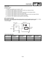
AUTO-CHOKE SYSTEM
This system is the parallel connection of the ignitor unit circuit and the thermo switch as shown,
detecting the engine temperature, and facilitates the restarting with the warm engine.
• Circuit diagram
Ignitor unit
Main switch
Thermo
switch
Fuse
Ignition
C.P.U
Battery
Auto-choke
• Auto-choke operation
Engine condition Start with the
cold engine
Thermo switch
OFF
Crank with the
cold engine
OFF
Crank with the
warm engine
ON
Restart with the
warm engine
ON
Ignitor unit circuit OFF
Auto-choke
Activates
ON
Activates
ON
Not activate
OFF
Not activate
1-3
IMPORTANT INFORMATION
GEN
INFO
EAS00020
IMPORTANT INFORMATION
PREPARATION FOR REMOVAL AND
DISASSEMBLY
1.Before removal and disassembly, remove all
dirt, mud, dust and foreign material.
2.Use only the proper tools and cleaning equipment.
Refer to the “SPECIAL TOOLS”.
3.When disassembling, always keep mated parts
together. This includes gears, cylinders, pistons and other parts that have been “mated”
through normal wear. Mated parts must always be reused or replaced as an assembly.
4.During disassembly, clean all of the parts and
place them in trays in the order of disassembly. This will speed up assembly and allow for
the correct installation of all parts.
5.Keep all parts away from any source of fire.
EAS00021
REPLACEMENT PARTS
1.Use only genuine Yamaha and MBK parts for
all replacements. Use oil and grease recommended by Yamaha or MBK for all lubrication
jobs. Other brands may be similar in function
and appearance, but inferior in quality.
EAS00022
GASKETS, OIL SEALS AND O-RINGS
1.When overhauling the engine, replace all gaskets, seals and O-rings. All gasket surfaces,
oil seal lips and O-rings must be cleaned.
2.During reassembly, properly oil all mating
parts and bearings and lubricate the oil seal
lips with grease.
1-4
IMPORTANT INFORMATION
GEN
INFO
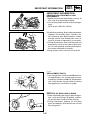
EAS00023
LOCK WASHERS / PLATES AND COTTER
PINS
1.After removal, replace all lock washers / plates
햲 and cotter pins. After the bolt or nut has
been tightened to specification, bend the lock
tabs along a flat of the bolt or nut.
햲
EAS00024
BEARINGS AND OIL SEALS
1.Install bearings and oil seals so that the manufacturer’s marks or numbers are visible. When
installing oil seals, lubricate the oil seal lips
with a light coat of lithium soap base grease.
Oil bearings liberally when installing, if appropriate.
햳 Oil seal
햳
CAUTION:
Do not spin the bearing with compressed air
because this will damage the bearing surfaces.
햲
햲 Bearing
EAS00025
CIRCLIPS
1.Before reassembly, check all circlips carefully
and replace damaged or distorted circlips.
Always replace piston pin clips after one use.
When installing a circlip 햲, make sure the
sharp-edged corner 햳 is positioned opposite
the thrust 햴 that the circlip receives.
햵 Shaft
햲
햴
햳
햵
1-5
CHECKING THE CONNECTIONS
GEN
INFO
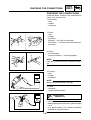
EAS00026
CHECKING THE CONNECTIONS
Check the leads, couplers, and connectors for
stains, rust, moisture, etc.
1.Disconnect:
• lead
• coupler
• connector
2.Check:
• lead
• coupler
• connector
Moisture → Dry with an air blower.
Rust/stains → Connect and disconnect several times.
3.Check:
• all connections
Loose connection → Connect properly.
햲
NOTE:
If the pin 햲 on the terminal is flattened, bend it
up.
4.Connect:
• lead
• coupler
• connector
+
NOTE:
Make sure all connections are tight.
-
5.Check:
• continuity
(with the pocket tester)
Pocket tester
90890-03112
+
NOTE:
• If there is no continuity, clean the terminals.
• When checking the wire harness, perform steps
1 to 3.
• As a quick remedy, use a contact revitalizer
available at most part stores.
1-6
-
SPECIAL TOOLS
GEN
INFO
EAS00027
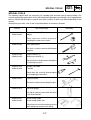
SPECIAL TOOLS
The following special tools are necessary for complete and accurate tune-up and assembly. Use
only the appropriate special tools as this will help prevent damage caused by the use of inappropriate
tools or improvised techniques. Special tools, part numbers or both may differ depending on the
country.
When placing an order, refer to the list provided below to avoid any mistakes.
Tool No.
90890-01083
90890-01084
Tool name/usage
Slide hammer bolt (M6)
Weight
These tools are used to remove or
installing the rocker arms shafts.
90890-01235
Rotor holding tool
This tool is used to remove the flywheel
magneto.
90890-01268
90890-01403
Ring nut wrench 햲
Steering nut wrench 햳
These tools are used to loosen and tighten
the steering ring nuts.
90890-01294
90890-01326
Damper rod holder
T-handle
These tools are used for disassembling
or assembling the front fork.
90890-01304
Piston pin puller
This tool is used to remove the piston pins.
90890-01312
Fuel level gauge
This tool is used to measure the fuel level
in the float chamber.
90890-01337
90890-01464
Clutch spring holder
Clutch spring holder arm
These tools are used for removing the nut
with holding the compression spring.
1-7
Illustration
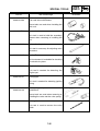
SPECIAL TOOLS
Tool No.
90890-01367
90890-01368
Tool name/usage
Fork seal driver weight
Frok seal driver attachment
These tools are used when installing the
fork seal.
90890-01701
Sheave holder
This tool is used to hold the secondary
sheave when removing or installing the
nut.
90890-03111
Valve adjusting tool
This tool is necessary for adjusting valve
clearance.
90890-03112
Pocket Tester
This instrument is invaluable for checking
the electrical system.
90890-03113
Engine tachometer
This tool is needed for detecting the
engine rpm.
90890-03141
Timing light
This tool is needed for detecting ignition
timing.
90890-04019
90890-04108
Valve spring compressor
Attachment
These tools are used when removing or
installing the valve and the valve spring.
90890-04116
Valve guide remover
This tool is used to remove the valve
guide.
1-8
GEN
INFO
Illustration
SPECIAL TOOLS
Tool No.
90890-04117
Tool name/usage
Valve guide installer
This tool is needed to install the valve
guide spring.
90890-04118
Valve guide reamer
This tool is used to rebore the valve guide.
90890-06754
Ignition checker
This instrument is necessary for checking
the ignition system components.
90890-85505
Yamaha bond No. 1215
This sealant (bond) is used for crankcase
mating surface, etc.
90890-03081
Compression gauge
This gauge is used to measure the engine
compression.
1-9
GEN
INFO
Illustration
SPEC
2
SPEC
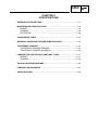
CHAPTER 2.
SPECIFICATIONS
GENERAL SPECIFICATIONS ...................................................................... 2-1
MAINTENANCE SPECIFICATIONS ............................................................. 2-4
ENGINE ................................................................................................... 2-4
CHASSIS ................................................................................................. 2-8
ELECTRICAL .........................................................................................2-10
CONVERSION TABLE ................................................................................ 2-12
GENERAL TIGHTENING TORQUE SPECIFICATIONS ............................ 2-13
TIGHTENING TORQUES ........................................................................... 2-14
TIGHTENING TORQUES (ENGINE) ..................................................... 2-14
TIGHTENING TORQUES (CHASSIS) ................................................... 2-16
LUBRICATION POINTS AND LUBRICANT TYPES .................................. 2-17
ENGINE ................................................................................................. 2-17
CHASSIS ............................................................................................... 2-18
COOLING SYSTEM DIAGRAMS ............................................................... 2-19
LUBRICATION DIAGRAMS ....................................................................... 2-21
CABLE ROUTING ....................................................................................... 2-23
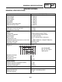
GENERAL SPECIFICATIONS
SPEC
SPECIFICATIONS
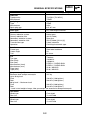
GENERAL SPECIFICATIONS
Item
XQ125 [XQ150]
Dimensions
Overall length
Overall width
Overall height
Seat height
Wheelbase
Minimum ground clearance
Minimum turning radius
1.920 mm
750 mm
1.180 mm
824 mm
1.400 mm
118 mm
2.050 mm
Weight
Wet (with oil and a full fuel tank)
Dry (without oil and fuel)
130 kg
124 kg
Engine
Engine type
Cylinder arrangement
Displacement
Bore x stroke
Compression ratio
Standard compression pressure (at sea level)
Starting system type
Lubrication system
Liquid cooled 4-stroke, SOHC
Forward inclined single cylinder
124 cm3 [152 cm3]
53.7 x 54.8 mm [59.5 x 54.8 mm]
11: 1
1.400kPa/500r/min (14kgf/cm2/500r/min)
Electric starter
Wet sump
Oil capacity
Engine oil
-20
-10
Temp.
0
10
30
20
40
10W/30
API STANDARD:
SE, SF, SG Type or
higher grade
10W/40
20W/40
20W/50
Periodic oil change
Total amount
Final gear case oil
Total amount
1.2 L
1.4 L
0.15 L
Coolant system
Radiator capacity (including all routes)
Coolant reservoir capacity
<from low to full level>
1.25 L
0.35 L
<0.15 L>
Air filter type
Dry element
Fuel
Recommended fuel
Fuel tank capacity
Regular unleaded gasoline
7.5 L
2-1
GENERAL SPECIFICATIONS
Item
SPEC
XQ125 [XQ150]
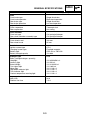
Carburetor
Type/quantity
Manufacturer
TK 5DS/1 [TK 5KD/1]
TEIKEI
Spark plug
Type
Manufacturer
Spark plug gap
CR8E
NGK
0.5~0.7 mm
Clutch type
Dry, centrifugal automatic
Transmission
Primary reduction system
Primary reduction ratio
Secondary reduction system
Secondary reduction ratio
Transmission type
Operation
Helical gear
40/15 (2.666)
Spur gear
44/12 (3.666) [42/14 (3)]
V-belt automatic
Centrifugal automatic type
Chassis
Frame type
Caster angle
Trail
Steel tube backbone
25°
81.3 mm
Tyre
Tyre type
Size (front)
Size (rear)
Manufacturer (front)
Manufacturer (rear)
Type (front)
Type (rear)
Tubeless
130/60-13
140/60-13
PIRELLI / CHENG SHIN
PIRELLI / CHENG SHIN
SL36 / MAXXIS
SL36 / MAXXIS
Tyre pressure (cold)
187 kg
Maximum load*-except motorcycle
Up to 90 kg load*
190 kPa (1.90 kgf/cm2)
Front
200 kPa (2.00 kgf/cm2)
Rear
90 kg load* ~ Maximum load*
200 kPa (2.00 kgf/cm2)
Front
220 kPa (2.20 kgf/cm2)
Rear
* Load is total weight of cargo, rider, passenger and accessories except motorcycle
Front wheel
Wheel type
Rim size
Cast wheel
13 x MT3.00
Rear wheel
Wheel type
Rim size
Cast wheel
13 x MT3.50
2-2
GENERAL SPECIFICATIONS
Item
SPEC
XQ125 [XQ150]
Brake
Front brake type
Front brake operation
Rear brake type
Rear brake operation
Single disc brake
Right hand operation
Single disc brake
Left hand operation
Suspension
Front suspension
Rear suspension
Telescopic fork
Unit swing
Shock absorber
Front fork type
Rear shock absorber assembly type
Coil spring/oil damper
Coil spring/oil damper
Wheel travel
Front wheel travel
Rear wheel travel
103 mm
95 mm
Electrical
Ignition system type
Charging system type
Battery type
Battery voltage/capacity
C.D.I
Flywheel magneto
CB7L-B2 or YB7L-B2
12V 8Ah
Headlight type
Bulbs (voltage/wattage x quantity)
Headlight
Auxiliary light
Brake/taillight
Turn signal light
Meter light
High beam indicator light
Turn indicator light
Coolant temperature warning light
12V 35W/35W x 2
12V 5W x 2
12V 21W/5W x 1
12V 10W x 4
12V 1.2W x 2
12V 1.2W x 1
12V 1.2W x 2
12V 1.2W x 1
Amperage for fuses
Main fuse
Radiator fan fuse
20 A
7.5 A
Bulb
2-3
SPEC
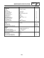
MAINTENANCE SPECIFICATIONS
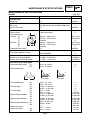
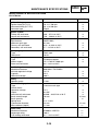
MAINTENANCE SPECIFICATIONS
* [XQ 150]
ENGINE
Item
Standard
Limit
Cylinder head
Warp limit
•••
Cylinder
Bore size
Out of round limit
53.700~53.705 mm [59.500~59.505 mm]*
•••
•••
0.05 mm
Camshaft
Drive system
Cam dimensions
Intake “A”
“B”
“C”
Exhaust “A”
“B”
“C”
Camshaft runout limit
0.03 mm
Chain drive (left)
C
A
B
30.811 ~ 30.911 mm
25.145 ~ 25.245 mm
5.666 m
30.811 ~ 30.911 mm
25.152 ~ 25.252 mm
5.659 m
•••
Cam chain
Cam chain type/No. of links
82 RH2005/94
Rocker arm/rocker armshaft
Rocker arm inside diameter
Rocker shaft outside diameter
12.000 ~ 12.018 mm
11.981 ~ 11.991 mm
Valve,valve seat, valve guide
Valve clearance (cold)
IN
EX
Valve dimensions
•••
30.711 mm
25.045 mm
•••
30.711 mm
25.052 mm
•••
0.03 mm
•••
12.030mm
11.950 mm
0.10 ~ 0.14 mm
0.16 ~ 0.20 mm
•••
•••
C
B
A
“A” head diameter
IN
EX
“B” face width
IN
EX
“C” seat width
IN
EX
Stem outside diameter
IN
EX
Guide inside diameter
IN
EX
Stem-to-guide clearence IN
EX
Stem runout limit
Valve seat width
IN
EX
Face width
26.9 ~ 27.1 mm
22.9 ~ 23.1 mm
2.687 ~ 3.252 mm
2.687 ~ 3.252 mm
0.9 ~ 1.1 mm
0.9 ~ 1.1 mm
4.475 ~ 4.490 mm
4.460 ~ 4.475 mm
4.500 ~ 4.512 mm
4.500 ~ 4.512 mm
0.01 ~ 0.037 mm
0.025 ~ 0.052
•••
0.9 ~ 1.1 mm
0.9 ~ 1.1 mm
2-4
Seat width
•••
•••
•••
•••
•••
1.6 mm
4.445 mm
4.430 mm
4.542 mm
4.542 mm
0.08 mm
0.10 mm
0.01 mm
1.6 mm
1.6 mm
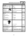
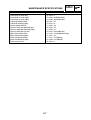
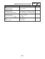
MAINTENANCE SPECIFICATIONS
SPEC
* [XQ 150]
Item
Valve spring
Free length
Set length (valve closed)
Compressed pressure
Tilt limit
Standard
IN/EX
IN/EX
IN/EX
IN/EX
Piston
Piston to cylinder
clearence
Piston size “D”
D
Measuring point “H”
Piston pin bore inside diameter
Piston pin outside diameter
Piston rings
Top ring:
Type
End gap (installed)
Side clearance (installed)
2 nd ring:
Type
End gap (installed)
Side clearence (installed)
Oil ring:
End gap (installed)
H
Limit
41.94 mm
37.5 mm
45.1 ~ 50.9 N
2.5° / 1.9 mm
39.84 mm
•••
•••
•••
0.025 ~ 0.035 mm
0.15 mm
53.670~53.687 mm [59.470~59.487mm]*
4.5 mm
15.002~15.013 mm
14.991~15.000 mm
•••
•••
15.045 mm
14.975 mm
Barrel
0.15 ~ 0.25 mm
0.03 ~ 0.07 mm
•••
0.50 mm
0.12 mm
Taper
0.15 ~ 0.30 mm
0.02 ~ 0.06 mm
•••
0.65 mm
0.12 mm
0.2 ~ 0.7 mm
•••
Crankshaft
Crank width “A”
Runout limit “C”
Big end side clearance “D”
47.950 ~ 48.000 mm
•••
0.15 ~ 0.45 mm
Automatic centrifugal clutch
Clutch shoe thickness
Clutch housing inside diameter
Weight outside diameter
Clutch-in revolution
Clutch-stall revolution
2.0 mm
120 mm [135 mm]*
20.0 mm
3,550 ~ 4,050 rpm [3,250 ~ 3,750 rpm]*
5,900 ~ 6900 rpm [5,600 ~ 6,400 rpm]*
V-Belt
V-belt width
22 mm
2-5
•••
0.03 mm
•••
1.0 mm
120.5 [135.5]*
19.5 mm
•••
•••
19 mm
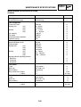
MAINTENANCE SPECIFICATIONS
SPEC
* [XQ 150]
Item
Carburetor
Type
I.D mark
Main jet (M.J)
Main air jet (M.A.J)
Jet needle (J.N)
Pilot air jet (P.A.J.1)
Needle jet (N.J)
Pilot jet (P.J)
Pilot screw (P.S)
Valve seat size (V.S)
Starter jet 1 (G.S.1)
Float height (F.L)
Engine idle speed
Standard
TK 5DS [TK 5KD]*
•••
#116 [#114]
ø1.0 [ø1.4]
4E31 (3/5) [4E32 (3/5)]*
ø1.30
2.590
#38 [#36]
2 1/4 ~ 2 3/4 [2 ~ 4]*
ø2.00
#45
5 ~ 6 mm
1.600 ~ 1.800 rpm
Limit
•••
•••
•••
•••
•••
•••
•••
•••
•••
•••
•••
Oil pump
Type
Tip clearence
Side clearance
Housing and rotor clearence
Trochoid
•••
•••
•••
Radiator
Type
Width/height thickness
Radiator cap opening pressure
Reservoir tank capacity
Cooling fin with electric fan
170 / 282 / 23 mm
100 ~ 120 kPa
0.35 L
•••
•••
•••
•••
Thermostatic valve
Manufacturer
Valve opening temperature
Valve full open temperature
ANGLI
82 °C
95 °C
•••
•••
•••
2-6
•••
0.15 mm
0.15 mm
0.17 mm
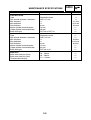
MAINTENANCE SPECIFICATIONS
Item
SPEC
Size
Crankshaft oil seal (left)
Crankshaft oil seal (right)
Crankshaft oil seal (right)
Camshaft bearing (left)
Camshaft bearing (right)
Starter clutch bearing
Primary drive gear bearing (left)
Primary drive gear bearing (right)
Primary drive gear oil seal
Main axle bearing (left)
Main axle bearing (right)
Drive axle bearing (left)
Drive axle bearing (right)
Drive axle oil seal
22 x 32 x 7
19 x 30 x 8 (Reinforced)
19 x 30 x 8 (Double lips)
20 x 42 x 12
15 x 32 x 9
17 x 35 x 10
25 x 52 x 15
17 x 40 x 12
25 x 42 x 6 (Double lips)
15 x 25 x 12 (Needle bearing)
12 x 37 x 12
17 x 47 x 14 (Sphere)
22 x 50 x 14 (Sphere)
32 x 52 x 7
2-7
MAINTENANCE SPECIFICATIONS
SPEC
MAINTENANCE SPECIFICATIONS
CHASSIS
Item
Standard
Steering system
Steering bearing type
Front suspension
Front fork travel
Spring rate
Stroke
(K1)
(K2)
(K1)
(K2)
Oil capacity
Oil grade
Inner tube outer diameter
Optional spring
Rear suspension
Shock absorber travel
Fitting length
Spring rate
(K1)
(K2)
(K3)
Stroke
(K1)
(K2)
(K3)
Spring preload adjusting position
Minimum
Standard
Maximum
Limit
Ball bearing
•••
103 mm
6.1 N/mm
7.8 N/mm
0 ~ 11 mm
11 ~ 87 mm
120 cm3
SAE20
33 mm
No
•••
•••
•••
•••
•••
•••
•••
•••
•••
95 mm
294 mm
8 N/mm
12 N/mm
18 N/mm
0 ~ 70 mm
70 ~ 100 mm
100 ~ 130 mm
•••
•••
•••
•••
•••
•••
•••
•••
1
1
4
•••
•••
•••
Front wheel
Type
Rim size
Rim material
Rim runout limit Radial
Lateral
Cast wheel
MT 3.00 x 13
Aluminium
•••
•••
•••
•••
•••
1 mm
0.5 mm
Rear wheel
Type
Rim size
Rim material
Rim runout limit Radial
Lateral
Cast wheel
MT 3.50 x 13
Aluminium
•••
•••
•••
•••
•••
1 mm
0.5 mm
2-8
MAINTENANCE SPECIFICATIONS
Item
Front disc brake
Type
Disc outside diameter x thickness
Min. thickness
Max deflection
Pad thickness
Master cylinder inside diameter
Caliper cylinder outside diameter
Brake fluid type
Standard
SPEC
Limit
Single disc brake
245 x 4.7 mm
•••
•••
4 mm
13 mm
28 mm
DOT #3 or DOT #4
•••
•••
4.2 mm
0.15 mm
0.8 mm
•••
•••
•••
Rear brake
Type
Disc outside diameter x thickness
Min. thickness
Max deflection
Pad thickness
Master cylinder inside diameter
Caliper cylinder outside diameter
Brake fluid type
Single disc brake
220 x 4.5 mm
•••
•••
4 mm
12 mm
32 mm
DOT #3 or #4
•••
•••
4.0 mm
0.15 mm
0.8 mm
•••
•••
•••
Brake lever
Brake lever free play (front)
Brake lever free play (rear)
Throttle cable free play
10 ~ 20 mm
10 ~ 20 mm
1.5 ~ 3.0 mm
2-9
•••
•••
•••
MAINTENANCE SPECIFICATIONS
SPEC
MAINTENANCE SPECIFICATIONS
ELECTRICAL
Item
Standard
Limit
Ignition timing
Ignition timing (B.T.D.C)
Advanced timing (B.T.D.C)
Advancer type
10° at 1.700 rpm
26° at 4.500 rpm
Digital
•••
•••
•••
Ignition system
Pickup coil resistance
Source coil resistance
248 ~ 372 Ω at 20°C
720 ~ 1080 Ω at 20°C
•••
•••
Ignition coil
Manufacturer
Minimum spark gap
Primary coil resistance
Secondary coil resistance
MORIYAMA
0.5 mm
0.32 ~ 0.48 Ω at 20°C
5.7 ~ 8.5 kΩ at 20°C
•••
•••
•••
Spark plug cap
Type
Resistance
Resin type
10 kΩ
•••
•••
Charging system
Type
Normal output
Stator coil resistance
Flywheel magneto
14 V 170W at 5.000 rpm
0.6 ~ 0.9 Ω at 20°C
•••
•••
Rectifier/regulator
Model/manufacturer
No load regulated voltage
Capacity
Withstand voltage
04012001 / FACOMSA
14.5 V
25 A
200 V
•••
•••
•••
Battery
Specific gravity
1.280
•••
Constant mesh type
•••
Electric starting system
Type
Starter motor:
Operation voltage
Output
Armature coil resistance
Brush overall length
Brush quantity
Spring force
Commutator diameter
Mica undercut (depth)
12 V
0.3 kW
0.0306 ~ 0.0374 Ω at 20°C
10 mm
2
5.6 ~ 8.3 N
22 mm
1.5 mm
Starter relay
Model/manufacturer
Amperage rating
Coil winding resistance
9768054 / JIDECO
100 A
4.2 ~ 4.6 Ω at 20°C
2-10
•••
•••
•••
3.5 mm
•••
21 mm
•••
•••
•••
•••
MAINTENANCE SPECIFICATIONS
Item
SPEC
Standard
Limit
Horn
Model/manufacturer
Maximum amperage
YF-12 / NIKKO
3A
•••
•••
Turn signal relay
Model/Manufacturer
Turn signal blinking frequency
800 TRANSVAL / 01.2320.01 GUILERA
65 ~ 95 cycles/min. / 70 ~ 90 cycles/min.
•••
•••
Fuel gauge
Model/manufacturer
Sender unit resistance - full
- empty
25.33.07 / MAXIMA
4 ~ 10 Ω
90 ~ 100 Ω
•••
•••
•••
Circuit breaker
Main
Radiator fan fuse
20 A x 1 pcs
7.5 A x 1 pcs
•••
•••
2-11
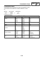
CONVERSION TABLE
SPEC
AS00028
CONVERSION TABLE
All specification data in this manual are listed in SI and METRIC UNITS.
Use this table to convert METRIC unit data to IMPERIAL unit data.
Ex.
METRIC
MULTIPLIER
IMPERERIAL
** mm x
0.03937
=
** in
2 mm x
0.03937
=
0.08 in
CONVERSION TABLE
METRIC TO IMPERIAL
Metric unit
Multiplier
Imperial unit
Torque
m•kg
m•kg
cm•kg
cm•kg
7.233
86.794
0.0723
0.8679
ft•lb
in•lb
ft•lb
in•lb
Weight
kg
g
2.205
0.03527
lb
oz
Speed
km/h
0.6214
mph
Distance
km
m
m
cm
mm
0.6214
3.281
1.094
0.3937
0.03937
mi
ft
yd
in
in
Volume/ Capacity
cc (cm3)
cc (cm3)
L (liter)
L (liter)
0.03527
0.06102
0.8799
0.2199
oz(IMP liq.)
cu•in
qt(IMP liq.)
gal(IMP liq.)
Misc.
kg/mm
kg/cm2
Centigrade (°C)
55.997
14.2234
9/5+32
lb/in
psi(lb/in2)
Fahrenheit (°F)
2-12
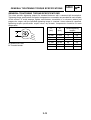
GENERAL TIGHTENING TORQUE SPECIFICATIONS
SPEC
EAS00029
GENERAL TIGHTENING TORQUE SPECIFICATIONS
This chart specifies tightening torques for standard fasteners with a standard ISO thread pitch.
Tightening torque specifications for special components or assemblies are provided for each chapter
of this manual. To avoid warpage, tighten multi-fastener assemblies in a crisscross pattern and
progressive stages until the specified tightening torque is reached. Unless otherwise specified,
tightening torque specifications require clean, dry threads. Components should be at room
temperature.
A
A
(nut)
B
(bolt)
10 mm
6 mm
12 mm
8 mm
15
1.5
14 mm
10 mm
30
3.0
17 mm
12 mm
55
5.5
19 mm
14 mm
85
8.5
22 mm
16 mm
130
13.0
B
A: Width across flats
B: Thread diameter
2-13
General tightening
torques
Nm
m•kg
6
0.6
TIGHTENING TORQUES
SPEC
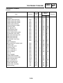
TIGHTENING TORQUES
ENGINE
Item
Oil check bolt
Spark plug
Cylinder, water drain bolt
Cylinder head and cylinder
Cylinder head and cylinder
Cylinder and crankcase
Camshaft bearing stopper
Camchain guide
Valve adjuster nut
Camshaft pinion bolt
Camshaft tensionner
Rocker shaft securing plate
Thermostatic valve cover
Water pump housing cover
Water pump housing
Water pump housing
Thermostatic valve cover
Oil pump
Engine drain plug
Inlet manifold on cylinder head
Air filter cover
V-belt air filter cover
Crankcase (left)
Cover, crankcase 1
Cover, crankcase 2
Cover, oil pump
Duct, air
Cover, magneto
Cylinder head stud bolt
Transmission oil drain plug
Engine oil drain plug
Cover, crankcase 3
Starter idle gear plate
Primary fixed sheave
Clutch carrier assembly
Clutch housing
Fastener
Bolt
Bolt
Nut
Bolt
Bolt
Bolt
Bolt
Nut
Bolt
Bolt
Bolt
Bolt
Bolt
Bolt
Bolt
Bolt
Bolt
Bolt
Bolt
Bolt
Bolt
Bolt
Bolt
Bolt
Bolt
Bolt
Stud
Plug
Plug
Bolt
Bolt
Nut
Nut
Nut
2-14
Thread
size
M6
M10
M6
M8
M6
M6
M6
M6
M5
M8
M6
M6
M6
M6
M6
M6
M6
M6
M35
M6
M6
M6
M6
M6
M6
M6
M6
M6
M8
M8
M8
M6
M6
M14
M36
M12
Q'ty
1
1
1
4
2
1
1
1
2
1
2
1
1
4
2
1
2
3
1
2
4
4
8
11
6
3
3
3
4
1
1
2
2
1
1
1
Tightening
torque
Nm
m•kg
9
13
8
22
12
12
12
6.5
6.5
30
10
10
9
10
7
7
9
65
32
10
6.5
6.5
9
10
10
6.5
7
7
13
22
22
6.5
7
60
90
55
0.9
1.3
0.8
2.2
1.2
1.2
1.2
0.65
0.65
0.3
1.0
1.0
0.9
1.0
0.7
0.7
0.9
6.5
3.2
1.0
0.65
0.65
0.9
1.0
1.0
0.65
0.7
0.7
1.3
2.2
2.2
0.65
0.7
6.0
9.0
5.5
Remarks
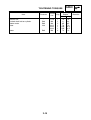
TIGHTENING TORQUES
Item
Fastener
Thermo unit
Coolant drain bolt on cylinder
Starter motor
Rotor
Bolt
Bolt
Nut
Stator
Bolt
2-15
Thread
size
Pt 1/8
M6
M6
M12
M16
M16
M6
Q'ty
1
1
2
1
1
1
3
SPEC
Tightening
torque
Nm
75
8
65
70
225
225
70
m•kg
7.5
0.8
6.5
7.0
22.5
22.5
7.0
Remarks
TIGHTENING TORQUES
SPEC
TIGHTENING TORQUES
CHASSIS
Item
Frame with engine bracket
Engine bracket 2 with 3
E/G bracket with E/G (with main stand)
Exhaust pipe stud bolt on cylinder
Muffler on rear arm
Rear arm on crankcase
Muffler protector
Seat rail with frame
Rear cushion with frame
Rear cushion with engine
Steering shaft
Handle with steering shaft
Master cylinder with handle
Seat lock
Box with seat rail
Fuel cock with tank
Handle seat with frame
Box with fuel tank
Screw tapping in plastic
Screw tapping in clip
Footrest board with frame
Fender on front fork
Cover handle with handle
Mainstand
Front wheel axle
Rear wheel axle
Front caliper on front fork
Rear caliper on rear arm
Front brake disc on wheel
Rear brake disc on wheel
Union bolt with caliper
Union bolt with master cylinder
Fastener
Thread
size
Q'ty
Bolt
Bolt
Bolt
Nut
Bolt
Bolt
Bolt
Bolt
Nut
Nut
Nut
Nut
Bolt
Bolt
Bolt
M10
M10
M10
M6
M8
M8
M6
M8
M10
M8
M25
M10
M6
M6
M6
1
2
2
2
3
2
2
8
1
1
3
1
2
2
2
Bolt
Bolt
Bolt
Bolt
Bolt
Bolt
Bolt
Nut
Nut
Nut
Bolt
Bolt
Bolt
Bolt
Bolt
Bolt
M6
M6
ø5
ø5
M6
M6
M5
M10
M12
M14
M8
M8
M8
M8
M10
M10
4
2
2-16
3
3
2
2
1
1
2
2
6
5
1
1
Tightening
torque
Nm
m•kg
42
55
42
11
27
27
4.5
26
32
18
4.2
5.5
4.2
1.1
2.7
2.7
0.45
2.6
3.2
1.8
60
8.5
4
8
2.5
4
4
3.25
2.25
4
4
4.5
42
70
104
23
23
23
23
23
23
6.0
0.85
0.4
0.8
0.25
0.4
0.4
0.33
0.23
0.4
0.4
0.45
4.2
7.0
10.4
2.3
2.3
2.3
2.3
2.3
2.3
Remarks
See chapter 7
“STEERING
HEAD”
LT
LUBRICATION POINTS AND LUBRICANT TYPES
SPEC
EAS00031
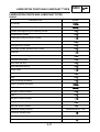
LUBRICATION POINTS AND LUBRICANT TYPES
ENGINE
Lubrication Point
Symbol
Oil seal lips
O-ring (Except V-belt drive unit)
Cylinder head tightening nut mounting surface
Crankshaft pin outside
Connecting rod big end thrust surface
Rotary filter inner surface
Drive gear inner surface
Cam chain outside sprocket inner surface
Piston pin
Piston outside and ring groove
Camshaft cam profile
Valve stem (IN, EX)
Valve stem end (IN, EX)
Rocker shaft
Valve rocker arm inner surface
Shaft
Shaft (Oil pump assembly)
Gasket (Oil pump assembly)
Holder
Idle gear 1 thrust surfaces
Shaft 1
Idle gear 2 thrust surfaces
Idle gear 2 inner surface
Main axle thrust surfaces
Crankcase mating surfaces
Yamaha bond No. 1215
Crankcase breather plug
Stator grommet
Yamaha bond No. 1215
Suction pipe
2-17
LUBRICATION POINTS AND LUBRICANT TYPES
SPEC
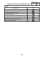
EAS00032
CHASSIS
Lubrication Point
Symbol
Front wheel oil seal lips (left/right)
Steering head pipe bearing (upper/lower)
Tube guide (throttle grip) inner surface
Brake cable (brake lever)
Brake lever and lever holder bolt sliding surface
Sidestand sliding surface
Centerstand sliding surface and mounting bolt
Centerstand stopper pivot shaft
2-18
COOLING SYSTEM DIAGRAMS
SPEC
EAS00033
COOLING SYSTEM DIAGRAMS
Radiator cap
Coolant tank cap
Coolant hose (cylinder head outlet)
Frame
Coolant tank
Coolant tank breather hose
Clip
Drain bolt
Thermo switch cover
Clip
Hose
Coolant hose (pump inlet)
Clamp
A Keep the smaller diameter for fixing on the
frame (ø 22).
B Keep the larger diameter for fixing the hose
(ø 24).
A
B
A
B
2-19
COOLING SYSTEM DIAGRAMS
SPEC
EAS00033(bis)
COOLING SYSTEM DIAGRAMS
Grommet
Coolant hose (pump inlet)
Radiator cap
Coolant tank
Coolant upper level mark
Coolant lower level mark
Coolant tank breather hose
Battery box
Drain bolt (on water pump)
Under cover
Thermo switch (on radiator)
Radiator
A Pass the hose under the seat rail fixation.
B Pass the hose under the frame down tube.
C Pass the hose through the under cover.
FRONT
C
A
REAR
l
B
2-20
LUBRICATION DIAGRAMS
SPEC
EAS00034
LUBRICATION DIAGRAMS
1 Lubrication of the cylinder head
Cylinder head
Cylinder
Crankcase
2 Lubrication of the crankshaft
Crankshaft
1
2
2-21