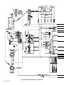
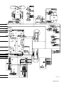
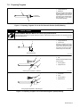
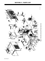
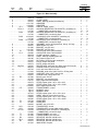
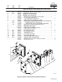
1
June 1993 Form: OM-206C Effective With Serial No. KD375312 OWNER’S MANUAL Maxstar 152 And 175 CC/DC Welding Power Source For GTAW And SMAW Welding 120 A At 25 V Or 140 A At 25.6 V, 100% Duty Cycle 152 Model: Single-Phase; 175 Model: Three-Phase Input Power Thermostat Protection Against Overheating Touch Start For GTAW Welding 14-Pin Remote Control Receptacle Read and follow these instructions and all safety blocks carefully. Give this manual to the operator. Have only trained and qualified persons install, operate, or service this unit. For help, call your distributor Call your distributor if you do not understand the directions. or: MILLER ELECTRIC Mfg. Co., P.O. Box 1079, Appleton, WI 54912 414-734-9821 cover 8/92 – SA-145 666-B PRINTED IN USA From Miller to You Thank you and congratulations on choosing Miller. Now you can get the job done and get it done right. We know you don’t have time to do it any other way. That’s why when Niels Miller first started building arc welders in 1929, he made sure his products offered long-lasting value and superior quality. Like you, his customers couldn’t afford anything less. Miller products had to be more than the best they could be. They had to be the best you could buy. Today, the people that build and sell Miller products continue the tradition. They’re just as committed to providing equipment and service that meets the high standards of quality and value established in 1929. This Owner’s Manual is designed to help you get the most out of your Miller products. Please take time to read the Safety precautions. They will help you protect yourself against potential hazards on the worksite. We’ve made installation and operation quick and easy. With Miller you can count on years of reliable service with proper maintenance. And if for some reason the unit needs repair, there’s a Troubleshooting section that will help you figure out what the problem is. The Miller is the first welding parts list will then help you to decide the equipment manufacturer in exact part you may need to fix the problem. the U.S.A. to be registered to the ISO 9001 Quality System Warranty and service information for your Standard. particular model are also provided. Working as hard as you do – every power source from Miller is backed by the most hassle-free warranty in the business. Miller offers a Technical Manual which provides more detailed service and parts information for your unit. To obtain a Technical Manual, contact your local distributor. Your distributor can also supply you with Welding Process Manuals such as SMAW, GTAW, GMAW, and GMAW-P. Miller Electric manufactures a full line of welders and welding related equipment. For information on other quality Miller products, contact your local Miller distributor to receive the latest full line catalog orindividual catalog sheets. To locate your nearest distributor or service agency call 1-800-4-A-Miller, or visit us at www.MillerWelds.com on the web. EMF INFORMATION NOTE Considerations About Welding And The Effects Of Low Frequency Electric And Magnetic Fields The following is a quotation from the General Conclusions Section of the U.S. Congress, Office of Technology Assessment, Biological Effects of Power Frequency Electric & Magnetic Fields – Background Paper, OTA-BP-E-53 (Washington, DC: U.S. Government Printing Office, May 1989): “. . . there is now a very large volume of scientific findings based on experiments at the cellular level and from studies with animals and people which clearly establish that low frequency magnetic fields can interact with, and produce changes in, biological systems. While most of this work is of very high quality, the results are complex. Current scientific understanding does not yet allow us to interpret the evidence in a single coherent framework. Even more frustrating, it does not yet allow us to draw definite conclusions about questions of possible risk or to offer clear science-based advice on strategies to minimize or avoid potential risks.” To reduce magnetic fields in the workplace, use the following procedures: 1. Keep cables close together by twisting or taping them. 2. Arrange cables to one side and away from the operator. 3. Do not coil or drape cables around the body. 4. Keep welding power source and cables as far away as practical. 5. Connect work clamp to workpiece as close to the weld as possible. About Pacemakers: The above procedures are among those also normally recommended for pacemaker wearers. Consult your doctor for complete information. mod10.1 4/93 TABLE OF CONTENTS SECTION 1 – SAFETY INFORMATION . . . . . . . . . . . . . . . . . . . . . . . . . . . . . . . . . . . . . . . . . . . . . . . . . . . . 1 SECTION 2 – SPECIFICATIONS 2-1. Volt-Ampere Curves . . . . . . . . . . . . . . . . . . . . . . . . . . . . . . . . . . . . . . . . . . . . . . . . . . . . . . . . . . . . 2-2. Duty Cycle . . . . . . . . . . . . . . . . . . . . . . . . . . . . . . . . . . . . . . . . . . . . . . . . . . . . . . . . . . . . . . . . . . . . 2 2 SECTION 3-1. 3-2. 3-3. 3-4. 3-5. 3-6. 3 – INSTALLATION Typical Process Connections . . . . . . . . . . . . . . . . . . . . . . . . . . . . . . . . . . . . . . . . . . . . . . . . . . . . Selecting A Location And Moving Welding Power Source . . . . . . . . . . . . . . . . . . . . . . . . . . . . Selecting And Preparing Weld Output Cables . . . . . . . . . . . . . . . . . . . . . . . . . . . . . . . . . . . . . . Connecting To Weld Output Receptacles . . . . . . . . . . . . . . . . . . . . . . . . . . . . . . . . . . . . . . . . . . Remote 14 Receptacle Information And Connections . . . . . . . . . . . . . . . . . . . . . . . . . . . . . . . Connecting Input Power . . . . . . . . . . . . . . . . . . . . . . . . . . . . . . . . . . . . . . . . . . . . . . . . . . . . . . . . 3 3 4 5 5 6 SECTION 4 – OPERATION . . . . . . . . . . . . . . . . . . . . . . . . . . . . . . . . . . . . . . . . . . . . . . . . . . . . . . . . . . . . . . . 8 SECTION 5-1. 5-2. 5-3. 5-4. 5-5. 5 – MAINTENANCE & TROUBLESHOOTING Routine Maintenance . . . . . . . . . . . . . . . . . . . . . . . . . . . . . . . . . . . . . . . . . . . . . . . . . . . . . . . . . . . Overload Protection . . . . . . . . . . . . . . . . . . . . . . . . . . . . . . . . . . . . . . . . . . . . . . . . . . . . . . . . . . . . Measuring Input Capacitor Voltage . . . . . . . . . . . . . . . . . . . . . . . . . . . . . . . . . . . . . . . . . . . . . . . Changing Amperage/Voltage Meter Hold Function . . . . . . . . . . . . . . . . . . . . . . . . . . . . . . . . . . Troubleshooting . . . . . . . . . . . . . . . . . . . . . . . . . . . . . . . . . . . . . . . . . . . . . . . . . . . . . . . . . . . . . . . 12 12 13 13 14 SECTION 6 – ELECTRICAL DIAGRAMS . . . . . . . . . . . . . . . . . . . . . . . . . . . . . . . . . . . . . . . . . . . . . . . . . . . 16 SECTION 7 – TUNGSTEN ELECTRODE 7-1. 7-2. Selecting Tungsten Electrode . . . . . . . . . . . . . . . . . . . . . . . . . . . . . . . . . . . . . . . . . . . . . . . . . . . . Preparing Tungsten . . . . . . . . . . . . . . . . . . . . . . . . . . . . . . . . . . . . . . . . . . . . . . . . . . . . . . . . . . . . 22 23 SECTION 8 – PARTS LIST Figure 8-1. Main Assembly . . . . . . . . . . . . . . . . . . . . . . . . . . . . . . . . . . . . . . . . . . . . . . . . . . . . . . . . . . . . Figure 8-2. Module, Power & Diode (175 Model Illustrated) . . . . . . . . . . . . . . . . . . . . . . . . . . . . . . . . 24 27 OM-206C – 6/93 SECTION 1 – SAFETY INFORMATION mod1.1 2/93 Read all safety messages throughout this manual. Obey all safety messages to avoid injury. Learn the meaning of WARNING and CAUTION. 1 2 2 WARNING ELECTRIC SHOCK can kill. MOVING PARTS can injure. • Do not touch live electrical parts. • Disconnect input power before • Keep away from moving parts. • Keep all panels and covers closed 4 installing or servicing. Safety Alert Symbol 2 Signal Word WARNING means possible death or serious injury can happen. CAUTION 3 1 when operating. CAUTION means possible minor injury or equipment damage can happen. 3 Statement Of Hazard And Result 4 Safety Instructions To Avoid Hazard 5 Hazard Symbol (If Available) 6 Safety Banner 5 READ SAFETY BLOCKS at start of Section 3-1 before proceeding. WARNING 6 Read safety blocks for each symbol shown. 7 7 NOTE NOTE Special instructions for best operation – not related to safety. Turn Off switch when using high frequency. Figure 1-1. Safety Information SECTION 2 – SPECIFICATIONS NOTE Unless otherwise noted, the 175 model is shown throughout this manual. Table 2-1. Welding Power Source Specification Description Type Of Output Constant Current (CC), Direct Current (DC) Welding Process Gas Tungsten Arc (GTAW), Shielded Metal Arc (SMAW) Welding Options See Rear Cover 152 Models 175 Models Rated Weld Output 120 Amperes, 25 Volts DC At 100% Duty Cycle (See Section 2-2) 140 Amperes, 26.5 Volts DC At 100% Duty Cycle (See Section 2-2) Type Of Input Power 230 Volts AC; 50/60 Hz; Single Phase 460 Volts AC; 50/60 Hz; Three-Phase Input Amperes At Rated Output 25 A 12.5 A KVA/KW Used At Rated Output 5.85 kVA/3.8 kW 9.56 kVA/5.26 kW Amperage Range 1-150 A 1-175 A Max. Open-Circuit Voltage 95 Volts DC 95 Volts DC Overall Dimensions Length: 16-1/2 in (419 mm); Width: 9-1/2 in (241 mm); Height: 8 in (203 mm) Length: 16-1/2 in (419 mm); Width: 9-1/2 in (241 mm); Height: 10 in (254 mm) Weight Net: 31 lb (14 kg); Ship: 36 lb (16 kg) Net: 39 lb (18 kg); Ship: 42 lb (19 kg) OM-206 Page 1 2-1. Volt-Ampere Curves The volt-ampere curves show the minimum and maximum voltage and amperage output capabilities of the welding power source. Curves of other settings fall between the curves shown. A. 152 Model B. 175 Model ssb1.1 10/91 – SB-151 604 / SB-143 476-B Figure 2-1. Volt-Ampere Curves 2-2. Duty Cycle CAUTION EXCEEDING DUTY CYCLE RATINGS will damage unit. • Do not exceed indicated duty cycles. warn7.1 2/92 Duty cycle is how long the unit can operate within a ten minute period without causing overheating or damage. A. 152 Model B. 175 Model This unit is rated at 100% duty cycle allowing continuous operation at rated load. sb1.1 2/92 – SB-121 591-B / SB-144 507-B Figure 2-2. Duty Cycle Chart OM-206 Page 2 SECTION 3 – INSTALLATION 3-1. Typical Process Connections SMAW Welding Power Source Work Remote Control GTAW 14 Pin Welding Power Source HF Unit Work Scratch Start Pulsed GTAW Or GTAW GTAW Pulse Control 14 Pin Welding Power Source Work Figure 3-1. Typical Process Connections 3-2. Selecting A Location And Moving Welding Power Source WARNING ELECTRIC SHOCK can kill. • • Do not touch live electrical parts. Disconnect input power conductors from deenergized supply line BEFORE moving welding power source. FIRE OR EXPLOSION can result from placing unit on, over, or near combustible surfaces. • • Do not locate unit on, over, or near combustible surfaces. Do not install unit near flammables. BLOCKED AIRFLOW causes overheating and possible damage to unit. FUMES can be hazardous; LACK OF FRESH AIR AND PROPER VENTILATION can be harmful. • • Do not breathe welding fumes. Place unit only where there is a good fresh air supply and proper ventilation. FALLING EQUIPMENT can cause serious personal injury and equipment damage. • • • Use handle to lift unit. Have person of adequate physical strength lift unit. Move unit with hand cart or similar device. • Do not block or filter airflow. Warranty is void if any type of filter is used. 2 1 Rear swarn11.1* 2/92 1 10 in (254 mm) Open Space On Right Side And Rear Of Unit For Good Airflow 2 Lifting Handle Use handle to move unit. 3 Rating Label Locate unit near correct input power supply. Right 3 Ref. SA-145 666-B Figure 3-2. Location And Movement Of Welding Power Source OM-206 Page 3 3-3. Selecting And Preparing Weld Output Cables 1 3 Weld Output Cable Determine total cable length in weld circuit and maximum welding amperes. Use Table 3-1 to select proper cable size. 4 OR Use shortest cables possible. Do not use damaged cables. 2 Terminal Lug Use lugs of proper amperage capacity and hole size for connecting to work clamp or electrode holder. 2 1 10 ft (3 m) 6 5 For Example, Total Cable Length In Weld Circuit = 20 ft (6 m) 3 Insulated Electrode Holder 4 GTAW Torch Install according to manufacturer’s instructions. 5 Work Clamp Install onto work cable. 6 10 ft (3 m) Tools Needed: Dinse-Type Connector Install onto weld cable as shown in Figure 3-4. sb6.2* 11/92 – S-0656 Figure 3-3. Selecting And Preparing Weld Output Cables Table 3-1. Weld Cable Size* Total Cable (Copper) Length In Weld Circuit Not Exceeding 100 ft (30 m) Or Less Welding Amperes 10 To 60% Duty Cycle 60 Thru 100% Duty Cycle 100 150 200 250 4 3 3 2 4 3 2 1 150 ft (45 m) 200 ft (60 m) 250 ft (70 m) 300 ft (90 m) 350 ft (105 m) 400 ft (120 m) 1/0 3/0 4/0 2-2/0 1/0 3/0 4/0 2-2/0 10 Thru 100% Duty Cycle 4 2 1 1/0 3 1 1/0 2/0 2 1/0 2/0 3/0 1 2/0 3/0 4/0 *Weld cable size (AWG) is based on either a 4 volts or less drop or a current density of not more than 300 circular mils per ampere. 1 3 2 1 Weld Output Cable 2 Handle 3 Sleeve S-0007-C Slide handle onto cable; strip cable and install sleeve. 1 in (26 mm) 5 4 3 4 Connector Body 5 Setscrew Insert cable with sleeve fully into connector body, tighten setscrew, and slide handle over connector. If job requires cable larger than 3/0 AWG, use 2 ft (610 mm) or shorter piece of 3/0 AWG cable for DinseType connector installation. Connect other end of short cable to the 4/0 or larger weld cable. Tools Needed: ST-156 496 Figure 3-4. Dinse-Type Connector Assembly OM-206 Page 4 3-4. Connecting To Weld Output Receptacles WARNING ELECTRIC SHOCK can kill; ARCING can burn skin or damage electrical equipment. • • • • Do not touch live electrical parts. Turn Off welding power source before making any weld output connections. Do not change position of welding cable connectors while welding. Be sure connectors are secure in receptacles before welding. 1 swarn12.2 2/93 4 1 Positive (+) Weld Output Receptacle 2 Negative (–) Weld Output Receptacle 3 Connector For Electrode Positive (DCEP), connect work cable connector to negative (–) receptacle and electrode holder cable connector to positive (+) receptacle. For Electrode Negative (DCEN), reverse cable connections. 2 Align keyway, insert connector, and turn clockwise. 4 3 Remote 14 Receptacle (see Section 3-5). Ref. SC-140 373 / Ref. ST-152 126 Figure 3-5. Connecting To Weld Output Receptacles 3-5. Remote 14 Receptacle Information And Connections 1 2 A B J K I 1 Remote 14 Receptacle RC7 2 Keyway 3 Plug 4 Threaded Collar To connect to this receptacle, align keyway, insert plug, and tighten threaded collar. H C L N D M G F E Socket Information: Remote Contactor A +15 volts dc B Contact closure to pin A completes +15 volts dc contactor control circuit. Remote Amperage/Voltage Control Rear Panel 3 4 C Command reference; +10 volts dc. D Control circuit common. E Input command signal (potentiometer wiper or 0 to +10 volts dc). K Chassis common. The remaining sockets are not used. sb7.1* 8/92 – Ref. SC-140 373 / Ref. S-0004-A / S-0750 Figure 3-6. Remote 14 Connections OM-206 Page 5 3-6. Connecting Input Power WARNING ELECTRIC SHOCK can kill. • • • • Do not touch live electrical parts. Turn Off welding power source, and disconnect input power before inspecting or installing. Have only qualified persons install unit. Installation must meet National Electrical Code and all other codes. swarn3.1 2/93 A. Connecting Input Power To 152 Models 1 1 230 VAC Cord/Plug 2 230 VAC Grounded Receptacle An individual branch circuit capable of carrying 25 amperes, and including overcurrent protection such as fuses or circuit breaker is required. Recommended standard fuse or circuit breaker rating is 40 amperes. 2 Connect input power plug to proper 230 VAC receptacle. ST-156 250 Figure 3-7. Input Power Connections B. Connecting Input Power To 175 Models Table 3-2. Electrical Service Requirements For 175 Ampere Models* Input Voltage 460 Input Amperes At Rated Output 12 Recommended Standard Fuse Or Circuit Breaker Rating In Input Conductor Size In AWG/Kcmil2 Max Input Conductor Length In Feet Grounding Conductor Size In * Amperes1 20 14 (Meters)3 AWG/Kcmil4 326 (99) 14 These values are calculated from the 1990 edition of the National Electrical Code (NEC). 1 Recommended fuse or circuit breaker size is that closest to 150% of rated input amperage of the welding power source. Article 630-12(a) of NEC allows fuse or circuit breaker sizing up to 200% of rated input amperage. 2 Input conductor size is for insulated copper wire with 75°C rating with not more than three single current-carrying conductors in a cable or raceway (Table 310-16 of NEC). 3 Maximum length is to prevent more than a 3% voltage drop between service entrance and input terminals of the welding power source (Articles 210-19(a) and 215-2(b) of NEC). 4 The grounding conductor shall be colored or identified as specified in the NEC. Grounding conductor size for copper wire is not required to be larger than input conductor (Article 250-95 of NEC). S-0092-F OM-206 Page 6 Have only qualified persons make this installation. Remove wrapper. 7 1 3 4 Line Disconnect Device Of Proper Rating 2 Input Conductors 3 Grounding Conductor Select size and length using Table 3-2. Conductor rating must comply with national, state, and local electrical codes. Strip 3/8 in (10 mm) insulation off all conductors. 6 2 5 4 Strain Relief Connector Insert conductors through strain relief. 5 Input Terminal Block 6 Line Terminals 7 Ground Terminal Insert grounding conductor into grounding terminal and tighten screw. Insert each input conductor into proper screw terminal L1, L2, or L3 on terminal block and tighten screws. Install and connect grounding conductor and input conductors in conduit or equivalent to deenergized line disconnect device. Be sure grounding conductor goes to an earth ground. Reinstall wrapper. 8 Overcurrent Protection Select type and size using Table 3-2. Install into deenergized line disconnect device (fused disconnect switch shown) 1 8 3 Tools Needed: 5/16 in ssb2.4* 3/93 – ST-145 667-B / SA-145 666-B Figure 3-8. Input Power Connections OM-206 Page 7 SECTION 4 – OPERATION WARNING ELECTRIC SHOCK can kill. • • • • ARC RAYS can burn eyes and skin; NOISE can damage hearing. Always wear dry insulating gloves. Insulate yourself from work and ground. Do not touch live electrical parts. Keep all panels and covers securely in place. • • MOVING PARTS can cause injury. FUMES AND GASES can be hazardous to your health. • • • • • Keep your head out of the fumes. Ventilate area, or use breathing device. Read Material Safety Data Sheets (MSDSs) and manufacturer’s instructions for material used. • • Do not weld near flammable material. Watch for fire; keep extinguisher nearby. Do not locate unit over combustible surfaces. Do not weld on closed containers. Allow work and equipment to cool before handling. 3 4 5 Keep away from moving parts. Keep all doors, panels, covers, and guards closed and securely in place. MAGNETIC FIELDS FROM HIGH CURRENTS can affect pacemaker operation. WELDING can cause fire or explosion. • • • • • Wear welding helmet with correct shade of filter. Wear correct eye, ear, and body protection. Pacemaker wearers keep away. Wearers should consult their doctor before going near arc welding, gouging, or spot welding operations. See Safety Precautions at beginning of manual for basic welding safety information. swarn6.1 10/91 6 1 Amperage Adjustment Control 2 Amperage Control Switch 3 Output (Contactor) Switch 4 Touch Start Switch 5 Weld Process Switch 6 Power Switch 7 Pilot Light 8 Optional Amperage/Voltage Meter And Switch 2 1 7 8 ST-152 127 Figure 4-1. Controls 1 2 3 1 Insulating Gloves 2 Safety Glasses With Side Shields 3 Welding Helmet Wear dry insulating gloves, safety glasses with side shields, and a welding helmet with a correct shade of filter (see ANSI Z49.1). sb3.1 10/91 Figure 4-2. Safety Equipment 1 1 Tools Needed: Work Clamp Connect work clamp to a clean, paint-free location on workpiece, as close to weld area as possible. Use wire brush or sandpaper to clean metal at weld joint area. Use chipping hammer to remove slag after welding. sb4.1 2/93 Figure 4-3. Work Clamp OM-206 Page 8 WARNING ELECTRIC SHOCK can kill. • • • Do not touch live electrical parts. Do not touch weld output receptacles when contactor is energized. Do not touch electrode and work clamp at the same time. swarn7.1* 10/91 1 Output (Contactor) Switch Use switch to select way of controlling output. For front panel control, place switch in On position. 1 For remote control, place switch in Remote 14 position (see Section 3-5). Weld output receptacles are energized when switch is On and Power is On. Figure 4-4. Output (Contactor) Switch 1 Amperage Adjustment Control Use control to select weld amperage. Amperage may be adjusted while welding. 2 Amperage Control Switch Use switch to select way of controlling amperage adjustment. For front panel control, place switch in the Panel position. 2 1 For remote control, place switch in Remote 14 position (see Section 3-5). 3 Remote Foot Control 4 Remote Hand Dial 5 Remote Fingertip Control See Example below. 5 EXAMPLE Of Combination Remote Amperage Control 4 3 Unit Minimum Control Setting (80 A) Set Switches Set Control Adjust Remote Control ST-159 059 / Ref. SC-140 372-C / S-0769 Figure 4-5. Amperage Controls OM-206 Page 9 1 Weld Process Switch Use switch to select type of weld output current. Use GTAW position for Gas Tungsten Arc Welding. Use SMAW position for Shielded Metal Arc Welding. 1 Switch position determines the operation of the Touch Start switch (see Figure 4-7). Figure 4-6. Weld Process Switch NOTE Touch Start switch must be in Off position when using a High-Frequency unit with this welding power source, or when using the SMAW welding process. 1 Touch Start Switch Use switch to select touch start On or Off. 2 1 3 1–2 Seconds “Touch” Do NOT Strike Like A Match! With touch start On, start an arc in GTAW welding as follows: 2 GTAW Electrode 3 Workpiece Touch tungsten electrode to workpiece at weld start point, hold electrode to workpiece for 1-2 seconds, and slowly lift electrode. An arc will form when electrode is lifted. Normal open-circuit voltage is not present before tungsten electrode touches workpiece; only a low sensing voltage is present between electrode and workpiece. The solid-state output contactor does not energize until after tungsten electrode is touching workpiece. This allows electrode to touch workpiece without overheating, sticking, or getting contaminated. Ref. S-156 279 Figure 4-7. Touch Start Switch 1 2 Use switch to turn unit and pilot light On and Off. 2 1 Figure 4-8. Power Switch And Pilot Light OM-206 Page 10 Power Switch Pilot Light 1 Amperage/Voltage Meter Meter displays amperage or voltage output. 2 1 Meter Switch Use switch to select amperage (A) or voltage (V) display. In Volts position, the meter displays the voltage at the weld output receptacles. In Amperage position, the meter displays the welding current during welding, and the preset amperage when welding is not taking place. 2 The meter displays the actual value for 15 seconds after welding stops (see Section 5-4). Figure 4-9. Optional Amperage/Voltage Meter And Switch Install & Connect Equipment Install & Connect High-Frequency Unit Turn On Shielding Gas Select Tungsten (See Section 7) Turn On High-Frequency Unit Insert Tungsten Into Torch Turn On Welding Power Source Put On Personal Safety Equipment Set Controls Begin Welding ssb8.1 12/92 Figure 4-10. Sequence Of Gas Tungsten Arc Welding (GTAW) Install & Connect Equipment Install & Connect Pulser Control Unit Set Controls Install & Connect High-Frequency Unit Turn On Shielding Gas Select Tungsten (See Section 7) Turn On Pulser And HighFrequency Unit Insert Tungsten Into Torch Turn On Welding Power Source Put On Personal Safety Equipment Begin Welding Figure 4-11. Sequence Of Gas Tungsten Arc Welding - Pulsed (GTAW-P) Install & Connect Equipment Select Electrode Put On Personal Safety Equipment Set Controls Insert Electrode Into Holder Turn On Welding Power Source Begin Welding ssb7.1 9/92 Figure 4-12. Sequence Of Shielded Metal Arc Welding (SMAW) OM-206 Page 11 SECTION 5 – MAINTENANCE & TROUBLESHOOTING WARNING ELECTRIC SHOCK can kill; SIGNIFICANT DC VOLTAGE exists after removal of input power. • • • Keep away from moving parts. Do not touch live electrical parts. Turn Off welding power source, disconnect input power, wait 60 seconds, measure voltage on input capacitors according to Section 5-3, and wait for voltage to drop to zero before touching any parts. HOT PARTS can cause severe burns. • MOVING PARTS can cause injury. Allow cooling period before maintaining or servicing. STATIC ELECTRICITY can damage parts on circuit boards. • Put on grounded wrist strap BEFORE handling boards or parts. Maintenance to be performed only by qualified persons. swarn8.1* 2/93 5-1. Routine Maintenance 3 Months Turn Off all power before maintaining. 3 Months Tape Or Replace Cracked Cables 3-3 Clean And Tighten Weld Connections Replace Unreadable Labels See Section 8 3-4 6 Months Replace Cracked Parts 14-Pin Cord OR –– –– Gas Hose Blow Out Or Vacuum Inside Torch Cable ST-145 666-B Figure 5-1. Maintenance Schedule 5-2. Overload Protection Thermostats TP1 and TP2 protect the unit from damage due to overheating. If the unit gets too hot, TP1 and/or TP2 open and weld output stops. The pilot light stays on, and the fan keeps running to cool the transformer. Wait several minutes before trying to weld. OM-206 Page 12 5-3. Measuring Input Capacitor Voltage READ SAFETY BLOCKS at start of Section 5 before proceeding. WARNING Turn Off welding power source and disconnect input power. Remove wrapper. 1 Input Capacitor C1 (Both Models) 2 Input Capacitor C2 (175 Models Only) 3 Voltmeter Check input capacitor(s). Measure the dc voltage across the positive (+) and negative (–) terminals every 30 seconds until voltage drops to 0 (zero) volts. Proceed with job inside unit. Reinstall wrapper when finished. Significant DC voltage can remain on capacitors after unit is Off. Always check capacitors as shown to be sure they have discharged before working on unit. 3 1 2 Tools Needed: 5/16 in ST-153 136-A Figure 5-2. Measuring Input Capacitor Voltage 5-4. Changing Amperage/Voltage Meter Hold Function READ SAFETY BLOCKS at start of Section 5 before proceeding. WARNING 2 1 2 1 ON OFF Hold Not Used Tools Needed: OFF 2 4 1 3 ON Hold Used The Amperage/Voltage meter is able to hold the displayed weld output value for 15 seconds after welding stops. This procedure allows the hold function to be turned On or Off. If the hold function is not used, the displayed value leaves when welding stops. Turn Off welding power source, disconnect input power, and check voltage on input capacitors according to Section 5-3 before proceeding. 1 A/V Meter Board PC3 2 DIP Switch S2 3 Toggle 1 4 Toggle 2 Set toggles in desired position. Reinstall wrapper. ST-158 741 Figure 5-3. Changing Amperage/Voltage Meter Hold Function OM-206 Page 13 5-5. Troubleshooting WARNING ELECTRIC SHOCK can kill. SIGNIFICANT DC VOLTAGE exists after removal of input power. • • MOVING PARTS can cause injury. • Do not touch live electrical parts. Turn Off welding power source, disconnect input power, wait 60 seconds, measure voltage on input capacitors according to Section 5-3, and wait for voltage to drop to zero before touching any parts. STATIC ELECTRICITY can damage parts on circuit boards. • • HOT PARTS can cause severe burns. • Keep away from moving parts. Put on grounded wrist strap BEFORE handling boards or parts. Use proper static-proof bags and boxes. Allow cooling period before servicing. Troubleshooting to be performed only by qualified persons. swarn9.1* 2/93 Table 5-1. Welding Trouble Trouble No weld output; unit completely inoperative. No weld output; fan motor running and pilot light on. Remedy Be sure Power switch is On. Limited output and low open-circuit voltage. 3-6A Be sure line disconnect switch is On (175 model). 3-6B Check line fuse(s) and replace if necessary. Reset circuit breakers. 3-6 Check for proper input power connections. 3-6 Check position of Output (Contactor) switch. Check position of Amperage Control switch. Figure 4-4 5-2 Figure 4-5 Have Factory Authorized Service Station/Service Distributor check control board PC1. –– Check incoming power for correct voltage. Replace line fuse if open or reset circuit breaker. 3-6 Check for proper input and output connections. Erratic or improper weld output. Figure 4-8 Secure power cord plug in receptacle (152 model). Thermostats TP1 and/or TP2 open (overheating). Allow fan to run; thermostat(s) closes when unit has cooled. Low weld output with no control. Section Tighten all welding cable connections. Check for proper size and type of cable. Check for proper input and output connections. Replace electrode. 3-3, 3-4, 3-6 3-3, 3-4 3-3 3-3, 3-4, 3-6 7-1, 7-2 Arc not forming when using Touch Start. Check electrode and workpiece, clean as needed to allow good contact. –– Fan motor does not run. Check and clear blocked fan blade; be sure blade is secure on shaft. –– Have Factory Authorized Service Station/Service Distributor check fan motor. –– OM-206 Page 14 Trouble Wandering arc; poor control of arc direction. Tungsten electrode oxidizing and not remaining bright after conclusion of weld. Remedy Section Reduce gas flow rate. –– Select proper size tungsten. 7-1 Properly prepare tungsten. 7-2 Shield weld zone from drafts. –– Increase postflow time. –– Check and tighten all gas fittings. –– Water in torch. Refer to torch Owner’s Manual for part(s) requiring replacement, and repair torch as necessary. –– OM-206 Page 15 Figure 6-1. Circuit Diagram For 152 Model SC-158 547-A SECTION 6 – ELECTRICAL DIAGRAMS OM-206 Page 16 OM-206 Page 17 Figure 6-2. Circuit Diagram For 175 Model SC-153 157 Figure 6-3. Wiring Diagram For 152 Model OM-206 Page 18 SD-158 546-A OM-206 Page 19 Figure 6-4. Wiring Diagram For 175 Model OM-206 Page 20 SD-153 153-A OM-206 Page 21 SECTION 7 – TUNGSTEN ELECTRODE mod2.1 3/93 NOTE For additional information, see your distributor for a handbook on the Gas Tungsten Arc Welding (GTAW) process. Wear clean gloves to prevent contamination of tungsten electrode. 7-1. Selecting Tungsten Electrode Table 7-1. Tungsten Size Amperage Range - Gas Type♦ - Polarity DC – Argon – Electrode Negative/Straight Polarity DC – Argon – Electrode Positive/Reverse Polarity AC – Argon – Using High Frequency AC – Argon – Balanced Wave Using High Freq. .010” Up to 15 * Up to 15 Up to 10 .020” 5-20 * 5-20 10-20 Electrode Diameter Pure Tungsten (Green Band) .040” 15-80 * 10-60 20-30 1/16” 70-150 10-20 50-100 30-80 3/32” 125-225 15-30 100-160 60-130 1/8” 225-360 25-40 150-210 100-180 5/32” 360-450 40-55 200-275 160-240 3/16” 450-720 55-80 250-350 190-300 1/4” 720-950 80-125 325-450 250-400 .010” Up to 25 * Up to 20 Up to 15 .020” 15-40 * 15-35 5-20 .040” 25-85 * 20-80 20-60 1/16” 50-160 10-20 50-150 60-120 3/32” 135-235 15-30 130-250 100-180 2% Thorium Alloyed Tungsten (Red Band) 1/8” 250-400 25-40 225-360 160-250 5/32” 400-500 40-55 300-450 200-320 3/16” 500-750 55-80 400-500 290-390 1/4” 750-1000 80-125 600-800 340-525 .010” * * Up to 20 Up to 15 .020” * * 15-35 5-20 .040” * * 20-80 20-60 1/16” * * 50-150 60-120 3/32” * * 130-250 100-180 1/8” * * 225-360 160-250 5/32” * * 300-450 200-320 3/16” * * 400-550 290-390 1/4” * * 600-800 340-525 Zirconium Alloyed Tungsten (Brown Band) ♦Typical argon shielding gas flow rates are 15 to 35 cfh (cubic feet per hour). *Not Recommended. The figures listed are intended as a guide and are a composite of recommendations from American Welding Society (AWS) and electrode manufacturers. S-0009 OM-206 Page 22 7-2. Preparing Tungsten 1 1 Tungsten Electrode 2 Balled End Ball end of tungsten before welding by applying either an ac amperage slightly higher than what is recommended for a given electrode diameter (see Table 7-1), or a dc electrode positive amperage. 1-1/2 Times Electrode Diameter 2 Ref. S-0161 Figure 7-1. Preparing Tungsten For AC Or DC Electrode Positive (DCEP) Welding CAUTION FLYING SPARKS AND HOT METAL can cause injury and start fires. • • Shape tungsten electrode only on grinder with proper guards in a safe location wearing proper face, hand, and body protection. Keep flammables away. warn2.1 9/91 1 2 1 Tungsten Electrode 2 Tapered End Grind end of tungsten on fine grit, hard abrasive wheel before welding. Do not use wheel for other jobs or tungsten can become contaminated causing lower weld quality. 2-1/2 Times Electrode Diameter Ref. S-0161 1 2 1 Stable Arc 2 Flat Diameter of this flat determines amperage capacity. 3 3 Grinding Wheel 4 Straight Ground 4 Ideal Tungsten Preparation – Stable Arc 1 2 Ref. S-0162 1 Arc Wander 2 Point 3 Grinding Wheel 4 Radial Ground 3 4 Wrong Tungsten Preparation – Wandering Arc Ref. S-0162 Figure 7-2. Preparing Tungsten For DC Electrode Negative (DCEN) Welding OM-206 Page 23 OM-206 Page 24 44 45 46 47 1 48 43 49 2 42 3 41 50 4 15 53 40 39 52 55 38 54 37 6 7 8 36 35 34 12 11 10 9 16 15 14 13 17 33 Figure 8-1. Main Assembly (175 Model Illustrated) 51 5 6 18 21 22 24 19 20 23 32 26 31 25 Fig 8-2 30 12 27 28 10 9 ST-145 668-E 29 SECTION 8 – PARTS LIST Item No. Dia. Mkgs. Part No. Description Quantity Model 152 175 Figure 8-1. Main Assembly . . . 1 . . . . . . . . . . . . . . . . 126 416 . . . 2 . . . . . . . . . . . . . . . . 126 415 . . . 3 . . . . . . . . . . . . . . . . 134 327 . . . 4 . . . . . . . . . . . . . . . +151 755 . . . 4 . . . . . . . . . . . . . . . +140 620 . . . 5 . . . . . . PC1 . . . . . 156 858 . . . . . . . . . . PLG1,2 . . . 131 052 . . . . . . . . . . . . . . . . . . . . . . 113 746 . . . . . . . . . . . PLG3 . . . . 131 056 . . . . . . . . . . . . . . . . . . . . . . 113 746 . . . . . . . . . . . PLG5 . . ++130 203 . . . . . . . . . . . . . . . . . . . . . . 113 746 . . . . . . . . . . . PLG8 . +++115 092 . . . . . . . . . . . . . . . . . . . . . . 113 746 . . . 6 . . . . . . . . . . . . . . . . 141 690 . . . 7 . . . . . . . . . . . . . . . . 140 627 . . . 8 . . . . . . . . . . . . . . . . 151 280 . . . 8 . . . . . . . . . . . . . . . +141 520 . . . 9 . . . . . . C1 . . . . . 151 281 . . . 9 . . . . . . C1,2 . . . . . 124 696 . . . 10 . . . . . . . . . . . . . . . . 006 426 . . . 11 . . . . . . . . . . . . . . . . 153 178 . . . 12 . . . . . . . . . . . . . . . . 136 190 . . . 13 . . . . . . . . . . . . . . . . 133 405 . . . 14 . . . . . . . . . . . . . . . . 130 215 . . . 14 . . . . . . . . . . . . . . . . 140 373 . . . 15 . . . . Neg,Pos . . . 129 525 . . . . . . . . . . . . . . . . . . . . . . 042 418 . . . 16 . . . . . . . . . . . . . . . . 145 743 . . . 17 . . . . . . . . . . . . . . . . . 111 443 . . . . . . . . . . . . . . . . . . . . . . 120 484 . . . 17 . . . . . . . . . . . . . . . . 010 916 . . . 18 . . . . . . TE1 . . . . . 147 386 . . . 19 . . . . . . . . . . . . . . . . 147 255 . . . 20 . . . . . . . . . . . . . . . . 119 757 . . . 21 . . . . . . . . . . . . . . . . 126 372 . . . 22 . . . . . . . . . . . . . . . . 140 626 . . . 23 . . . . . . . . . . . . . . . +128 803 . . . 24 . . . . . . CT1 . . . . . 150 925 . . . 25 . . . . . . . . . . . . . . . . . Fig 8-2 . . . 26 . . . . . . . . . . . . . . . . . Fig 8-2 . . . 27 . . . . . . . . . . . . . . . . 141 515 . . . 28 . . . . . . . . . . . . . . . . 126 026 . . . 29 . . . . . . . . . . . . . . . . 119 943 . . . 29 . . . . . . . . . . . . . . . . 140 380 . . . 30 . . . . . . . Z1 . . . . . . 130 794 . . . 30 . . . . . . . Z1 . . . . . . 131 866 . . . 31 . . . . . . . . . . . . . . . . 019 663 . . . 32 . . . . . . HD1 . . . . . 156 149 . . . 32 . . . . . . HD1 . . . . . 124 684 . . . . . . . . . . . PLG10 . . . . 130 204 . . . . . . . . . . . . . . . . . . . . . . 114 066 . . . 33 . . . . . . . T1 . . . . . . 151 585 . . . 33 . . . . . . . T1 . . . . . . 141 669 . . . 34 . . . . . . R2 . . . . . 139 203 . . . 34 . . . . . . R2,3 . . . . . 139 203 . . . 35 . . . . . . R1 . . . . . 136 076 . . . 36 . . . . . . . . . . . . . . . . 141 422 . . HANDLE . . . . . . . . . . . . . . . . . . . . . . . . . . . . . . . . . . . . . . . . . . . . . 1 . . . . . . CLAMP, saddle . . . . . . . . . . . . . . . . . . . . . . . . . . . . . . . . . . . . . . . . 1 . . . . . . LABEL, warning general precautionary . . . . . . . . . . . . . . . . . . . 1 . . . . . . WRAPPER . . . . . . . . . . . . . . . . . . . . . . . . . . . . . . . . . . . . . . . . . . . 1 . . WRAPPER . . . . . . . . . . . . . . . . . . . . . . . . . . . . . . . . . . . . . . . . . . . . . . . . . . . . CIRCUIT CARD, control . . . . . . . . . . . . . . . . . . . . . . . . . . . . . . . . 1 . . . . . . HOUSING RECEPTACLE & SOCKETS, (consisting of) . . . . . 2 . . . . . . . . CONNECTOR, rect skt 24-18ga . . . . . . . . . . . . . . . . . . . . . . . 16 . . . . . . HOUSING RECEPTACLE & SOCKETS, (consisting of) . . . . . 1 . . . . . . . . CONNECTOR, rect skt 24-18ga . . . . . . . . . . . . . . . . . . . . . . . 14 . . . . . . HOUSING PLUG & SOCKETS, (consisting of) . . . . . . . . . . . . 1 . . . . . . . . CONNECTOR, rect skt 24-18ga . . . . . . . . . . . . . . . . . . . . . . . 12 . . . . . . HOUSING PLUG & SOCKETS, (consisting of) . . . . . . . . . . . . 1 . . . . . . . . CONNECTOR, rect skt 24-18ga . . . . . . . . . . . . . . . . . . . . . . . 8 . . . . . . GROMMET, scr No. 8/10 panel hole .281sq .197 high . . . . . . 6 . . . . . . INSULATION, PC card . . . . . . . . . . . . . . . . . . . . . . . . . . . . . . . . . 1 . . . . . . BRACKET, mtg PC card . . . . . . . . . . . . . . . . . . . . . . . . . . . . . . . . 1 . . BRACKET, mtg PC card . . . . . . . . . . . . . . . . . . . . . . . . . . . . . . . . . . . . . . . . . CAPACITOR, elctlt 1600uf 400VDC . . . . . . . . . . . . . . . . . . . . . . 1 . . CAPACITOR, elctlt 1700uf 400VDC . . . . . . . . . . . . . . . . . . . . . . . . . . . . . . . CLAMP, capacitor 2.000dia . . . . . . . . . . . . . . . . . . . . . . . . . . . . . 1 . . . . . . LABEL, warning exploding parts etc . . . . . . . . . . . . . . . . . . . . . . . . . . . . . . . NUT, speed U type 10-32 . . . . . . . . . . . . . . . . . . . . . . . . . . . . . . . 2 . . . . . . NUT, speed 10-24 flat type rectangular . . . . . . . . . . . . . . . . . . . 1 . . . . . . PLATE, output rear panel . . . . . . . . . . . . . . . . . . . . . . . . . . . . . . . 1 . . PLATE, output rear panel . . . . . . . . . . . . . . . . . . . . . . . . . . . . . . . . . . . . . . . . RECEPTACLE, twlk insul fem (Dinse type) 50/70 series . . . . 2 . . . . . . CONNECTOR KIT, Dinse male 50 series . . . . . . . . . . . . . . . . . 2 . . . . . . LUG, univ w/scr 600V 2-14 wire . . . . . . . . . . . . . . . . . . . . . . . . . . . . . . . . . . BUSHING, strain relief .240/.510 ID x .875mtg hole . . . . . . . . 1 . . CORD SET, 250V 6-50P 12ga 3/c 8ft . . . . . . . . . . . . . . . . . . . . 1 . . CONNECTOR, clamp cable .750 . . . . . . . . . . . . . . . . . . . . . . . . . . . . . . . . . BLOCK, term 70A 3P . . . . . . . . . . . . . . . . . . . . . . . . . . . . . . . . . . . . . . . . . . . BRACKET, mtg terminal block . . . . . . . . . . . . . . . . . . . . . . . . . . . . . . . . . . . . BAR, support heat sink bottom . . . . . . . . . . . . . . . . . . . . . . . . . . 1 . . . . . . STRIP, polyest gl lam .187 x .250 x .625 . . . . . . . . . . . . . . . . . . 1 . . . . . . STRIP, polyest gl lam .187 x .500 x 2.250 . . . . . . . . . . . . . . . . . 1 . . . . . . BAR, support heat sink top . . . . . . . . . . . . . . . . . . . . . . . . . . . . . 1 . . . . . . TRANSFORMER, current . . . . . . . . . . . . . . . . . . . . . . . . . . . . . . 1 . . . . . . MODULE, power . . . . . . . . . . . . . . . . . . . . . . . . . . . . . . . . . . . . . . 1 . . . . . . MODULE, diode . . . . . . . . . . . . . . . . . . . . . . . . . . . . . . . . . . . . . . . 1 . . . . . . STRIP, polyest gl lam .187 x .500 x .812 . . . . . . . . . . . . . . . . . . 1 . . . . . . LABEL, warning electric shock can kill . . . . . . . . . . . . . . . . . . . . 1 . . . . . . STRIP, polyest gl lam .187 x .500 x 6.500 . . . . . . . . . . . . . . . . . 1 . . STRIP, polyest gl lam .187 x .500 x 8.687 . . . . . . . . . . . . . . . . . . . . . . . . . . STABILIZER . . . . . . . . . . . . . . . . . . . . . . . . . . . . . . . . . . . . . . . . . . 1 . . STABILIZER . . . . . . . . . . . . . . . . . . . . . . . . . . . . . . . . . . . . . . . . . . . . . . . . . . . MOUNT, nprn 15/16 OD . . . . . . . . . . . . . . . . . . . . . . . . . . . . . . . . 4 . . . . . . TRANSDUCER, current . . . . . . . . . . . . . . . . . . . . . . . . . . . . . . . . 1 . . TRANSDUCER, current 300A module supply . . . . . . . . . . . . . . . . . . . . . . HOUSING PLUG & SOCKETS, (consisting of) . . . . . . . . . . . . 1 . . . . . . . . CONNECTOR, rect skt 20-14ga . . . . . . . . . . . . . . . . . . . . . . . 3 . . . . . . TRANSFORMER, pwr main . . . . . . . . . . . . . . . . . . . . . . . . . . . . . 1 . . TRANSFORMER, pwr main 325 . . . . . . . . . . . . . . . . . . . . . . . . . . . . . . . . . . RESISTOR, WW fxd 30W 8K ohm . . . . . . . . . . . . . . . . . . . . . . . 1 . . RESISTOR, WW fxd 30W 8K ohm . . . . . . . . . . . . . . . . . . . . . . . . . . . . . . . . RESISTOR, WW fxd 30W 200 ohm . . . . . . . . . . . . . . . . . . . . . . 1 . . . . . . INSULATOR, flat pack . . . . . . . . . . . . . . . . . . . . . . . . . . . . . . . . . 1 . . . . 1 1 1 1 1 2 16 1 14 1 12 1 8 6 1 1 2 2 1 4 2 1 2 2 1 1 1 1 1 1 1 1 1 1 1 1 1 1 1 4 1 1 3 1 2 1 1 OM-206 Page 25 Item No. Dia. Mkgs. Part No. Description Quantity Model 152 175 Figure 8-1. Main Assembly (Continued) . . . 37 . . . . . . . S1 . . . . . 090 328 . . SWITCH, tgl DPST 40A 600VAC . . . . . . . . . . . . . . . . . . . . . . . . 1 . . . . . . . . . . . PLG11 . . . . 115 094 . . HOUSING PLUG & SOCKETS, (consisting of) . . . . . . . . . . . . 1 . . . . . . . . . . . . . . . . . . . . . . 113 746 . . . . CONNECTOR, rect skt 24-18ga . . . . . . . . . . . . . . . . . . . . . . . 4 . . . . . . . . . . . RC11 . . . . 115 090 . . HOUSING PLUG & PINS, (consisting of) . . . . . . . . . . . . . . . . . 1 . . . . . . . . . . . . . . . . . . . . . . 114 656 . . . . CONNECTOR, rect pin 24-18ga . . . . . . . . . . . . . . . . . . . . . . . 4 . . . . . . . . . . . . . . . . . . . . . . 047 838 . . BLANK, snap-in nyl 1.000mtg hole . . . . . . . . . . . . . . . . . . . . . . . 1 . . . 37 . . . . . . . S1 . . . . . 091 441 . . SWITCH, tgl 3PST 40A 600V . . . . . . . . . . . . . . . . . . . . . . . . . . . . . . . . . . . . . 38 . . . . . . . . . . . . . . . . 148 297 . . NUT, speed U type 10-32 . . . . . . . . . . . . . . . . . . . . . . . . . . . . . . . 2 . . . . . . . 39 . . . . . . . . . . . . . . . . 146 684 . . INSULATOR, switch pwr . . . . . . . . . . . . . . . . . . . . . . . . . . . . . . . . . . . . . . . . . 40 . . . . . . CR1 . . . . . 106 462 . . RELAY, encl 24VDC DPDT . . . . . . . . . . . . . . . . . . . . . . . . . . . . . 1 . . . . . . . 41 . . . . . . . . . . . . . . . . . . . . . . . . . . . NAMEPLATE, (order by model and serial number) . . . . . . . . . 1 . . . . . . . 42 . . . . . . PL1 . . . . . 135 199 . . LIGHT, ind red lens 28V . . . . . . . . . . . . . . . . . . . . . . . . . . . . . . . . 1 . . . . . . . 43 . . . . . . S2-5 . . . . . 120 376 . . SWITCH, rocker SPDT 4A 250VAC . . . . . . . . . . . . . . . . . . . . . . 4 . . . . . . . 44 . . . . . . . . . . . . . . . ♦042 880 . . METER KIT A & V DC, (consisting of) . . . . . . . . . . . . . . . . . . . . 1 . . . 44 . . . . . . . . . . . . . . . ♦042 613 . . METER KIT A & V DC, (consisting of) . . . . . . . . . . . . . . . . . . . . . . . . . . . . . . 45 . . . . . . . . . . . . . . . . 133 644 . . . . FRAME, snap-in switch rocker panel mtg . . . . . . . . . . . . . . . 1 . . . . . . . 46 . . . . . . PC3 . . . . . 157 587 . . . . CIRCUIT CARD, meter . . . . . . . . . . . . . . . . . . . . . . . . . . . . . . . 1 . . . . . . . . . . . . . . . PLG9 . . . . 089 222 . . . . CONNECTOR, plug 11posn . . . . . . . . . . . . . . . . . . . . . . . . . . . 1 . . . . . . . . . . . . . . . . . . . . . . . . . . 136 339 . . COVER, opening meter . . . . . . . . . . . . . . . . . . . . . . . . . . . . . . . . 1 . . . . . . . 47 . . . . . . . . . . . . . . . . 097 922 . . KNOB, pointer . . . . . . . . . . . . . . . . . . . . . . . . . . . . . . . . . . . . . . . . 1 . . . . . . . 48 . . . . . . R4 . . . . . 073 562 . . POTENTIOMETER, C sltd sft 1/T 2W 10K ohm . . . . . . . . . . . 1 . . . . . . . 49 . . . . . . . . . . . . . . . . 151 533 . . PANEL, front . . . . . . . . . . . . . . . . . . . . . . . . . . . . . . . . . . . . . . . . . . 1 . . . 49 . . . . . . . . . . . . . . . . 146 333 . . PANEL, front . . . . . . . . . . . . . . . . . . . . . . . . . . . . . . . . . . . . . . . . . . . . . . . . . . . . 50 . . . . . . . . . . . . . . . . 134 756 . . LABEL, warning electric shock can kill . . . . . . . . . . . . . . . . . . . . . . . . . . . . . . 51 . . . . . . C12 . . . . . 135 286 . . CAPACITOR . . . . . . . . . . . . . . . . . . . . . . . . . . . . . . . . . . . . . . . . . 1 . . . . . . . 52 . . . . . . C13 . . . . . 135 289 . . CAPACITOR . . . . . . . . . . . . . . . . . . . . . . . . . . . . . . . . . . . . . . . . . 1 . . . . . . . 53 . . . . . . C14 . . . . . 141 524 . . LEAD ASSEMBLY, elect . . . . . . . . . . . . . . . . . . . . . . . . . . . . . . . . 1 . . . . . . . 53 . . . . . . C15 . . . . . 141 525 . . LEAD ASSEMBLY, elect . . . . . . . . . . . . . . . . . . . . . . . . . . . . . . . . 1 . . . . . . . 53 . . . . . . C16 . . . . . 141 522 . . LEAD ASSEMBLY, elect . . . . . . . . . . . . . . . . . . . . . . . . . . . . . . . . 1 . . . . . . . 53 . . . . . . C17 . . . . . 141 523 . . LEAD ASSEMBLY, elect . . . . . . . . . . . . . . . . . . . . . . . . . . . . . . . . 1 . . . . . . . 54 . . . . . . RC7 . . . . . 143 976 . . RECEPTACLE w/SOCKETS, (consisting of) . . . . . . . . . . . . . . 1 . . . . . . . . . . . . . . . . . . . . . . . . . . 079 534 . . . . CONNECTOR, circ skt push-in 14-18ga . . . . . . . . . . . . . . . . 14 . . . . . . . . . . . . . . . . . . . . . . . . . . 134 734 . . CONNECTOR, circ 14 pin plug Amp 213571-2 . . . . . . . . . . . . . . . . . . . . . . 134 731 . . CONNECTOR, circ pin push-in 14-18ga Amp 213603-1 . . . . . . . . . . . . . . . . . . . . . . 079 739 . . CONNECTOR, circ clamp str rlf .703 max cable OD Amp 206322-2 (or) . . . . . . . . . . . . . . . . . . . . . . 143 922 . . CONNECTOR, circ clamp str rlf .453 max cable OD Amp 206070-3 . . . 55 . . . . . . . . . . . . . . . . 151 535 . . CASE SECTION, bottom/rear . . . . . . . . . . . . . . . . . . . . . . . . . . . 1 . . . 55 . . . . . . . . . . . . . . . . 140 621 . . CASE SECTION, bottom/rear . . . . . . . . . . . . . . . . . . . . . . . . . . . . . . . . . . . . . . . . . . . . . . . . . . . . . . . . 161 098 . . BUS BAR, output . . . . . . . . . . . . . . . . . . . . . . . . . . . . . . . . . . . . . . 1 . . . . +When ordering a component originally displaying a precautionary label, the label should also be ordered. ++Included with Interconnecting Circuit Card PC2. +++Part of 042 880 and 042 613 Meter Kit Options. ♦OPTIONAL BE SURE TO PROVIDE MODEL AND SERIAL NUMBER WHEN ORDERING REPLACEMENT PARTS. OM-206 Page 26 1 2 1 1 1 1 4 1 1 1 1 1 1 1 1 1 1 1 1 1 1 1 1 14 1 1 Quantity Item No. Dia. Mkgs. Part No. Model Description 152 175 Figure 8-2. Module, Power & Diode (Fig 8-1 Item 25 & 26) . . . 1 . . . . . . C11 . . . . . 093 085 . . . 2 . . . . . VR1-3 . . . . 090 304 . . . 3 . . . . . . . . . . . . . . . . 158 540 . . . 3 . . . . . . . . . . . . . . . . 141 668 . . . 4 . . . . . . . . . . . . . . . . 156 247 . . . 4 . . . . . . . . . . . . . . . . 155 426 . . . 5 . . . . . . . . . . . . . . . . 134 209 . . . 6 . . . . . . . . . . . . . . . . 000 366 . . . 7 . . . . . . FM . . . . . 156 246 . . . . . . . . . . . . RC6 . . . . . 135 409 . . . . . . . . . . . . . . . . . . . . . . 114 656 . . . 7 . . . . . . FM . . . . . 141 518 . . . 8 . . . . . . . . . . . . . . . . 146 238 . . . 9 . . . . . . . . . . . . . . . +151 484 . . . . . . . . . . . . . . . . . . . . . . 153 178 . . . 9 . . . . . . . . . . . . . . . . 141 423 . . . 10 . . . . . . Q1-4 . . . . 149 207 . . . 11 . . . . . . D5 . . . . . 149 215 . . . 12 . . . . . . TP2 . . . . . 032 810 . . . 13 . . . . . . SR1 . . . . . 149 218 . . . 13 . . . . . . SR1 . . . . . 149 217 . . . 14 . . . . . . PC2 . . . . . 151 284 . . . 14 . . . . . . PC2 . . . . . 141 662 . . . . . . . . . . . . . . . . . . . . . . 010 913 . . . . . . . . . . . . . . . . . . . . . . 601 835 . . CAPACITOR, polye MF .0047uf 1000V . . . . . . . . . . . . . . . . . . . 1 . . . . . . VARISTOR, 220 joule 730VDC . . . . . . . . . . . . . . . . . . . . . . . . . . . . . . . . . . . MODULE, pwr (consisting of) . . . . . . . . . . . . . . . . . . . . . . . . . . . 1 . . MODULE, pwr (consisting of) . . . . . . . . . . . . . . . . . . . . . . . . . . . . . . . . . . . . . . BLADE, fan 6 in 4wg 30deg .252 bore CCW . . . . . . . . . . . . . 1 . . . . KIT, fan blade (consisting of) . . . . . . . . . . . . . . . . . . . . . . . . . . . . . . . . . . . . . . . NUT, speed push-on-type .250 . . . . . . . . . . . . . . . . . . . . . . . . . . . . . . . . . . RING, retainer E .250 shaft grv x .025thk . . . . . . . . . . . . . . . . . . . . . . . . . . MOTOR, fan 120/230V 2600RPM w/36V sec (consisting of) 1 . . . . . . CONNECTOR & PINS, (consisting of) . . . . . . . . . . . . . . . . 1 . . . . . . . CONNECTOR, rect pin 24-18ga Molex 39-00-0040 . . . 8 . . . . MOTOR, fan 230/460V 2600RPM w/36V sec . . . . . . . . . . . . . . . . . . . . . . . BRACKET, mtg fan motor . . . . . . . . . . . . . . . . . . . . . . . . . . . . . 1 . . . . . . . . HEAT SINK, pwr module . . . . . . . . . . . . . . . . . . . . . . . . . . . . . . 1 . . . . LABEL, warning exploding parts etc . . . . . . . . . . . . . . . . . . . . 1 . . . . HEAT SINK, pwr module . . . . . . . . . . . . . . . . . . . . . . . . . . . . . . . . . . . . . . . . . KIT, transistor mosfet . . . . . . . . . . . . . . . . . . . . . . . . . . . . . . . . . 4 . . . . . . . . KIT, diode fast recovery . . . . . . . . . . . . . . . . . . . . . . . . . . . . . . . . . . . . . . . . . . THERMOSTAT, NC . . . . . . . . . . . . . . . . . . . . . . . . . . . . . . . . . . 1 . . . . . . . . KIT, rectifier integ 100A . . . . . . . . . . . . . . . . . . . . . . . . . . . . . . . 1 . . . . KIT, rectifier integ 100A . . . . . . . . . . . . . . . . . . . . . . . . . . . . . . . . . . . . . . . . . . CIRCUIT CARD, interconnecting . . . . . . . . . . . . . . . . . . . . . . . 1 . . . . CIRCUIT CARD, interconnecting . . . . . . . . . . . . . . . . . . . . . . . . . . . . . . . . . . WASHER, flat brs .218 ID x .460 OD x .031thk . . . . . . . . . . . . . . . . . . . . . NUT, brs hex 10-32 . . . . . . . . . . . . . . . . . . . . . . . . . . . . . . . . . . . . . . . . . 1 3 1 1 1 1 1 1 1 4 1 1 1 1 4 4 1 23 2 22 17 21 20 5 19 4 18 16 6 7 15 8 9 10 11 3 12 13 14 ST-145 796-A Figure 8-2. Module, Power & Diode (175 Model Illustrated) OM-206 Page 27 Quantity Item No. Dia. Mkgs. Part No. Model Description 152 175 Figure 8-2. Module, Power & Diode (Fig 8-1 Item 25 & 26) (Continued) . . . . . . . . . . . PLG6 . . . . ...................... ...................... ...................... . . . 15 . . . . . . VR4 . . . . . . . . 16 . . . . . . R10 . . . . . . . . 17 . . . . . . DM1 . . . . . . . . 17 . . . . . . DM1 . . . . . . . . 18 . . . . . . D5,6 . . . . . . . . 19 . . . . . . . . . . . . . . . . . . . 19 . . . . . . . . . . . . . . . . . . . 20 . . . . . . R9 . . . . . . . . 20 . . . . . . R5 . . . . . . . . 21 . . . . . . D1,2 . . . . . . . . 22 . . . . . C9,10 . . . . . . . 23 . . . . . . TP1 . . . . . 115 092 113 746 010 193 601 835 004 113 030 839 151 479 140 492 151 229 151 470 140 622 098 324 098 324 151 431 098 325 129 552 . . CONNECTOR & SOCKETS, (consisting of) . . . . . . . . . . . . . . . 1 . . . . CONNECTOR, rect skt 24-18 ga Molex 39-00-0038 . . . . . . 8 . . WASHER, flat brs .218 ID x .460 OD x .031thk . . . . . . . . . . . . 4 . . . . . . NUT, brs hex 10-32 . . . . . . . . . . . . . . . . . . . . . . . . . . . . . . . . . . . . 4 . . . . . . VARISTOR, 40 joule 390VDC . . . . . . . . . . . . . . . . . . . . . . . . . . . 1 . . . . . . RESISTOR, WW fxd 5W 220 ohm . . . . . . . . . . . . . . . . . . . . . . . 1 . . . . . . MODULE, diode (consisting of) . . . . . . . . . . . . . . . . . . . . . . . . . . 1 . . MODULE, diode (consisting of) . . . . . . . . . . . . . . . . . . . . . . . . . . . . . . . . . . . . . KIT, diode ultra fast recovery . . . . . . . . . . . . . . . . . . . . . . . . . . 1 . . . . . . . . HEAT SINK, diode module . . . . . . . . . . . . . . . . . . . . . . . . . . . . 1 . . . . HEAT SINK, diode module . . . . . . . . . . . . . . . . . . . . . . . . . . . . . . . . . . . . . . . RESISTOR, WW fxd 25W 5 ohm . . . . . . . . . . . . . . . . . . . . . . 1 . . . . RESISTOR, WW fxd 25W 5 ohm . . . . . . . . . . . . . . . . . . . . . . . . . . . . . . . . . KIT, diode ultra fast recovery . . . . . . . . . . . . . . . . . . . . . . . . . . 1 . . . . . . . . CAPACITOR, polyp film .027uf 630V . . . . . . . . . . . . . . . . . . . 2 . . . . . . . . THERMOSTAT, NC . . . . . . . . . . . . . . . . . . . . . . . . . . . . . . . . . . 1 . . . . +When ordering a component originally displaying a precautionary label, the label should also be ordered. BE SURE TO PROVIDE MODEL AND SERIAL NUMBER WHEN ORDERING REPLACEMENT PARTS. OM-206 Page 28 2 2 1 1 1 1 1 1 1 2 1 OPTIONS AND ACCESSORIES BACKLIT LCD METER KIT (#042 613 Factory) For 175 (#042 880 Factory) For 152 (#042 614 Field) For all models A presettable, lighted digital display meter. Meter displays preset amperage, weld amperage, or weld voltage. UNIVERSAL LARGE CYLINDER CART (#042 934) Maxstar can mount on this cart along with argon cylinder. Will accommodate 6 to 9 in. (152 to 228 mm) diameter, and 24 to 56 in. (610 to 1422 mm) high. UNIVERSAL RUNNING GEAR/CYLINDER RACK (#042 454) Height: 17–1/4 in. (438 mm) Length: 29–1/2 in. (749 mm) Width: 14–1/4 in. (362 mm) Accepts “R” size gas cylinders. Shipped disassembled. CARRYING CART (#056 301) Height: 34 in. (864 mm) Width: 30 in. (762 mm) Depth: 17 in. (432 mm) Maxstar and Intellitig units fit nicely on this cart. EXTENSION CORDS For 14–Pin Remote Controls (#122 972) 10 ft. (3 m) (#122 973) 25 ft. (7.6 m) (#122 974) 50 ft. (15.2 m) (#122 975) 75 ft. (22.9 m) RFC-14 FOOT CONTROL (#129 339) Heavy–duty foot current and contactor control. 20 ft. (6 m) cord and 14–pin plug. RFC-E FOOT CONTROL (#042 856) Lightweight, com–pact foot control. 15 ft. (4.6 m) cord and 14–pin plug. RCC-14 REMOTE CONTACTOR AND CURRENT CONTROL (#151 086) Fastens to TIG torch handle. Includes 28 ft. (8.5 m) cord and plug. AMTV REMOTE CONTACTOR AND CURRENT CONTROL (#152 608) Fastens to TIG torch handle using velcro strips. PC–300 PULSED GTAW (DC TIG) CONTROL (#042 297) The PC–300 provides two internally switchable scales. An inverter power source can utilize the 0.5 to 20 pulses–per–second scale or the 10 to 300 pulses–per–second scale. The PC–300 can be used with welding power sources with or without built–in high–frequency, or with external high–frequency units. Front panel controls provide: • Peak Amperage Adjustment • Background Amperage Adjustment • Pulses–Per–Second Adjustment • Percent On–Time Adjustment • Amperage Remote/Panel • Output Contactor On/Off • Pulser On/Off • Power On/Off A remote control receptacle is also included for use with a remote hand or foot control. An 8 ft. (2.4 m) interconnecting cord and 115 VAC power cord are provided (115 VAC power is required). MILLER EXPERT PROGRAM (#042 849) Maxstar 152 (#042 850) Maxstar 175 The Miller Expert Program is an easy–to–use computerized software program to systematically guide you through the repair of your equipment. Refer to Literature Index No. AV/6.0. INTERNATIONAL-STYLE CONNECTORS (Will accept Dinse or other International connectors.) Maxstar power sources are equipped with International–style connectors for secondary connections. (Power source is shipped with two 50 mm male International–style plugs for use with #1 or #2 AWG size cable.) INTERNATIONAL–STYLE CONNECTOR KIT (#042 418) 50 mm Required if male plugs shipped with power source must be replaced or if additional plugs are needed. Kit includes one International–style male plug, which attaches to the work and/or weld cables and plugs into the International–style receptacles on the power source. Accepts #1 or #2 AWG size cable. EXTENSION KIT FOR INTERNATIONAL–STYLE CABLE CONNECTORS (#042 419) 50 mm Used to adapt or extend weld and/or work cables. Kit includes one male International–style plug and one in–line female International–style receptacle. Accepts #1 or #2 AWG size cable. INTERNATIONAL/TWECO ADAPTER (#042 465) A one–piece adapter which has an International–style male plug (to power source) on one end and a female Tweco receptacle (for weld cable connection) on the other end. INTERNATIONAL/CAM–LOK ADAPTER (#042 466) A one–piece adapter which has an International–style male plug (to power source) on one end and a female Cam–Lok receptacle (for weld cable connection) on the other end. 3/93 OPTIONS AND ACCESSORIES INTERNATIONAL TIG TORCH CONNECTOR KIT (#135 492) 80 Amp Torch (#135 493) 150 Amp Torch (#135 494) 200 Amp Torch* (#135 495) 250/350 Amp Water–Cooled Torch For direct connection of one–piece torches to power sources with International–style connectors. Note: Two–piece torches do not require this connector kit. They can use one of the two International–style connectors supplied with the power source. *May not be compatible with competitive brand torches. TOTAL TIG INSTALLATION KIT For Total TIG system, select one each of the following items: • Welding power source • TIGtorch (recommended torches listed below) • TIG kit (see kits listed below) • Remote control (optional) • Snap Start (optional) TIG TORCHES AND CONNECTING KITS For hand–held, manual applications. For complete information on all Miller TIG torches and accessories, see Literature Index No. TG/1.0. Explanation of Model Description MT = Miller torch XX = Model number of torch V = Gas valve in torch handle* 12 = 12–1/2 ft. (3.8 m) cable 25 = 25 ft. (7.6 m) cable 1 = One–piece, high–flex cable 80 AMP AIR–COOLED MODELS (#116 091) MT–24–12–1 (#116 092) MT–24–25–1 Note: International Connector Kit (#135 492) must be used with the 80 Amp TIG torches listed. KIT FOR MT–24 SERIES AIR–COOLED MODELS (#142 413) 12–1/2 ft. (3.8 m) length (#142 414) 25 ft. (7.6 m) length Kit includes: • Hose and hardware hook–up kit (THK–2) • Consumable accessory kit (TAK–4) - three sizes (.040 in., 1/16 in., 3/32 in.) of collets, collet bodies, cups, and 2% thoriated tungsten • Regulator/flowmeter (HRF–2425) • Work cable with clamp (clamp rated for 350 Amps), 12–1/2 ft. (3.8 m) or 25 ft. (7.6 m) lengths to match TIG torch length 150 AMP AIR–COOLED MODELS (#116 107) MT–17–12–1 (#116 108) MT–17–25–1 (#116 111) MT–17V–12–1* (#116 112) MT–17V–25–1* Note: International Connector Kit (#135 493) must be used with the 150 Amp TIG torches listed. KIT FOR MT–17 SERIES AIR–COOLED TIG TORCH (#129 590) 12–1/2 ft. (3.8 m) length (#129 589) 25 ft. (7.6 m) length Kit includes: • Hose and hardware hook–up kit (THK–2) • Consumable accessory kit (TAK–1) - one backcap and three sizes (.040 in., 1/16 in., 3/32 in.) of collets, collet bodies, cups, and 2% thoriated tungsten • Regulator/flowmeter (HRF–2425) • Work cable with clamp (clamp rated for 350 Amps), 12–1/2 ft. (3.8 m) or 25 ft. (7.6 m) lengths to match TIG torch length 200 AMP AIR–COOLED MODELS (#116 123) MT–26–12–1 (#116 124) MT–26–25–1 (#116 127) MT–26V–12–1* (#116 128) MT–26V–25–1* Note: International Connector Kit (#135 494) must be used with the 200 Amp TIG torches listed. KIT FOR MT–26 SERIES AIR–COOLED TIG TORCH (#129 588) 12–1/2 ft. (3.8 m) length (#129 587) 25 ft. (7.6 m) length Kit includes: • Hose and hardware hook–up kit (THK–2) • Consumable accessory kit (TAK–3) - one backcap and three sizes (1/16 in., 3/32 in., 1/8 in.) of collets, collet bodies, cups, and 2% thoriated tungsten • Regulator/flowmeter (HRF–2425) • Work cable with clamp (clamp rated for 350 Amps), 12–1/2 ft. (3.8 m), or 25 ft. (7.6 m) lengths to match TIG torch length *Torches with manual gas valves are recommended for use with “Touch Start”. When the Maxstar is used with an optional Snap Start or Intellitig, torches with gas valves are not recommended. 3/93 Effective January 1, 2001 (Equipment with a serial number preface of “LB” or newer) This limited warranty supersedes all previous Miller warranties and is exclusive with no other guarantees or warranties expressed or implied. Warranty Questions? Call 1-800-4-A-MILLER for your local Miller distributor. Your distributor also gives you ... Service You always get the fast, reliable response you need. Most replacement parts can be in your hands in 24 hours. Support Need fast answers to the tough welding questions? Contact your distributor. The expertise of the distributor and Miller is there to help you, every step of the way. * LIMITED WARRANTY – Subject to the terms and conditions below, Miller Electric Mfg. Co., Appleton, Wisconsin, warrants to its original retail purchaser that new Miller equipment sold after the effective date of this limited warranty is free of defects in material and workmanship at the time it is shipped by Miller. THIS WARRANTY IS EXPRESSLY IN LIEU OF ALL OTHER WARRANTIES, EXPRESS OR IMPLIED, INCLUDING THE WARRANTIES OF MERCHANTABILITY AND FITNESS. Within the warranty periods listed below, Miller will repair or replace any warranted parts or components that fail due to such defects in material or workmanship. Miller must be notified in writing within thirty (30) days of such defect or failure, at which time Miller will provide instructions on the warranty claim procedures to be followed. Miller shall honor warranty claims on warranted equipment listed below in the event of such a failure within the warranty time periods. All warranty time periods start on the date that the equipment was delivered to the original retail purchaser, or one year after the equipment is sent to a North American distributor or eighteen months after the equipment is sent to an International distributor. 1. 5 Years Parts – 3 Years Labor * * 2. 3 Years — Parts and Labor * * * * * * 3. Original main power rectifiers Inverters (input and output rectifiers only) Transformer/Rectifier Power Sources Plasma Arc Cutting Power Sources Semi-Automatic and Automatic Wire Feeders Inverter Power Supplies Intellitig Engine Driven Welding Generators (NOTE: Engines are warranted separately by the engine manufacturer.) 1 Year — Parts and Labor * * * * * * * * * * * * * * * * * DS-2 Wire Feeder Motor Driven Guns (w/exception of Spoolmate Spoolguns) Process Controllers Positioners and Controllers Automatic Motion Devices RFCS Foot Controls Induction Heating Power Sources Water Coolant Systems HF Units Grids Maxstar 140 Spot Welders Load Banks Miller Cyclomatic Equipment Running Gear/Trailers Plasma Cutting Torches (except APT & SAF Models) Field Options (NOTE: Field options are covered under True Blue for the remaining warranty period of the product they are installed in, or for a minimum of one year — whichever is greater.) 4. 6 Months — Batteries 5. 90 Days — Parts * * MIG Guns/TIG Torches Induction Heating Coils and Blankets * * * * * APT, ZIPCUT & PLAZCUT Model Plasma Cutting Torches Remote Controls Accessory Kits Replacement Parts (No labor) Spoolmate Spoolguns Canvas Covers Miller’s True Blue Limited Warranty shall not apply to: 1. Consumable components; such as contact tips, cutting nozzles, contactors, brushes, slip rings, relays or parts that fail due to normal wear. 2. Items furnished by Miller, but manufactured by others, such as engines or trade accessories. These items are covered by the manufacturer’s warranty, if any. 3. Equipment that has been modified by any party other than Miller, or equipment that has been improperly installed, improperly operated or misused based upon industry standards, or equipment which has not had reasonable and necessary maintenance, or equipment which has been used for operation outside of the specifications for the equipment. MILLER PRODUCTS ARE INTENDED FOR PURCHASE AND USE BY COMMERCIAL/INDUSTRIAL USERS AND PERSONS TRAINED AND EXPERIENCED IN THE USE AND MAINTENANCE OF WELDING EQUIPMENT. In the event of a warranty claim covered by this warranty, the exclusive remedies shall be, at Miller’s option: (1) repair; or (2) replacement; or, where authorized in writing by Miller in appropriate cases, (3) the reasonable cost of repair or replacement at an authorized Miller service station; or (4) payment of or credit for the purchase price (less reasonable depreciation based upon actual use) upon return of the goods at customer’s risk and expense. Miller’s option of repair or replacement will be F.O.B., Factory at Appleton, Wisconsin, or F.O.B. at a Miller authorized service facility as determined by Miller. Therefore no compensation or reimbursement for transportation costs of any kind will be allowed. TO THE EXTENT PERMITTED BY LAW, THE REMEDIES PROVIDED HEREIN ARE THE SOLE AND EXCLUSIVE REMEDIES. IN NO EVENT SHALL MILLER BE LIABLE FOR DIRECT, INDIRECT, SPECIAL, INCIDENTAL OR CONSEQUENTIAL DAMAGES (INCLUDING LOSS OF PROFIT), WHETHER BASED ON CONTRACT, TORT OR ANY OTHER LEGAL THEORY. ANY EXPRESS WARRANTY NOT PROVIDED HEREIN AND ANY IMPLIED WARRANTY, GUARANTY OR REPRESENTATION AS TO PERFORMANCE, AND ANY REMEDY FOR BREACH OF CONTRACT TORT OR ANY OTHER LEGAL THEORY WHICH, BUT FOR THIS PROVISION, MIGHT ARISE BY IMPLICATION, OPERATION OF LAW, CUSTOM OF TRADE OR COURSE OF DEALING, INCLUDING ANY IMPLIED WARRANTY OF MERCHANTABILITY OR FITNESS FOR PARTICULAR PURPOSE, WITH RESPECT TO ANY AND ALL EQUIPMENT FURNISHED BY MILLER IS EXCLUDED AND DISCLAIMED BY MILLER. Some states in the U.S.A. do not allow limitations of how long an implied warranty lasts, or the exclusion of incidental, indirect, special or consequential damages, so the above limitation or exclusion may not apply to you. This warranty provides specific legal rights, and other rights may be available, but may vary from state to state. In Canada, legislation in some provinces provides for certain additional warranties or remedies other than as stated herein, and to the extent that they may not be waived, the limitations and exclusions set out above may not apply. This Limited Warranty provides specific legal rights, and other rights may be available, but may vary from province to province. miller_warr 10/01 Owner’s Record Please complete and retain with your personal records. Model Name Serial/Style Number Purchase Date (Date which equipment was delivered to original customer.) Distributor Address City State Zip For Service Call 1-800-4-A-Miller or see our website at www.MillerWelds.com to locate a DISTRIBUTOR or SERVICE AGENCY near you. Always provide Model Name and Serial/Style Number. Contact your Distributor for: Welding Supplies and Consumables Options and Accessories Personal Safety Equipment Service and Repair Miller Electric Mfg. Co. An Illinois Tool Works Company 1635 West Spencer Street Appleton, WI 54914 USA Replacement Parts Training (Schools, Videos, Books) International Headquarters–USA USA Phone: 920-735-4505 Auto-Attended USA & Canada FAX: 920-735-4134 International FAX: 920-735-4125 Technical Manuals (Servicing Information and Parts) Circuit Diagrams European Headquarters – United Kingdom Phone: 44 (0) 1204-593493 FAX: 44 (0) 1204-598066 Welding Process Handbooks www.MillerWelds.com Contact the Delivering Carrier for: File a claim for loss or damage during shipment. For assistance in filing or settling claims, contact your distributor and/or equipment manufacturer’s Transportation Department. PRINTED IN USA 2002 Miller Electric Mfg. Co. 1/02