1
Manual
26" RIDING MOWER
SIDE DISCHARGE
ELECTRIC START
Catalog No.
WE261
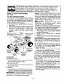
' MPORTANT:
Read and follow all Safety
Rules and Instructions
,operating
Patents Pending
532 43 32-03 Rev. 9
before
this equipment.
Warranty ................................................. 2
Safety Rules ........................................... 3
Product Specifications ............................ 6
Assembly/Pro-Operation ........................ 7
Operation .............................................. 10
Maintenance Schedule ......................... 16
Maintenance
.........................................
Service and Adjustments ......................
Storage .................................................
Troubleshooting
....................................
Repair Parts ..........................................
16
20
24
25
27
LIMITED WARRANTY
The Manufacturer warrants to the original consumer purchaser that this product as manufactured is free from defects ir_materials and workmanship. For a period cf two (2) years from date of purchase by the original consumer purchaser, we will repair or
replace, at our option, without charge for parts or labor incurred in replacing parts, any part which we find to be defective due
to materials or workmanship, This Warranty is sub)oct to the fotlow_ng limitations and exclas_cns.
I.
This warranty does not apply te the engine, battery (except as noted below} or components parts thereof. Please refer to
the opplicable manufacturer's warran.ty on these items.
2.
Transparta.tien charges for the movement of any power eqL_ipment unit or attachment are the raspcnsiblllty cf the purchaser, Transportation charges for any parts submitted for replacement under this warranty must be paid by the purchaser
unless such return is requested by the manufacturer.
3.
Battery Warranty: On products equipped with a Battery, we will replase, without charge to yea, any battery which we find
to be defective in manufacture, during the first ninety (90) days of ownership. After ninety (90) days. we will exchange the
Battery, charging you t/12 ofthe price of a new Battery for each full month f_om the date of the original sale. Sattery must
be maintained in accordance with the instructions furnished.
4.
The Warranty does not apply to any products used for renta! ar commercial purposes.
5.
This Warranty applies only to products which have been properIy assembled, adjusted, operated, and maintained in accordance with the instructionsfurnished, This Warrar, ty does not appIy to any product which hes been subjected to alteration, misuse, ab_se, improper assembIy or iastallatleo, delivery damage, or to normal wear of the product.
6.
Exclusion:
Excluded from this Warranty ere belts, blades, blade adapters,
hardware and normal maintenance,
7.
in the event you have a claim under"this Warranty. you must return the product tc ar_authorized
normal wear, normal adjustments,
standa_
service deaJec
Should you have any unanswered questions eaneeming this Warraoty, please contact:
HOP
In Canada contact'.
Outdoor Produ_.-ts Castcmar Service Sept.
9335 Hands Corners Parkway
Charlotte, NC 282.6g USA
HOP
5855 Terry Pc× Way
Missiaseuga, Ontario
L5V 3E4
giving the model number, serial number and date of purchase of your product and the name and address of the authorized
dealer from whom it was purchased,
THIS WARP.AN'I'Y DOES NOT APPLY TO INCIDENTAL OR CONSEQUENTIAL DAMAGES AND ANY IMPUED WARRANTIES ARE LIMITED TO THE SAME TIME PERIODS STATED HEREIN FOR OUR E_PRESSEO WARRANTIES. Some ames
do not alIow the limitation of consequential damages or limEtatiansof how long an implied Warranty may last, so the above
limitations ar exclusions may not apply to you. This Warranty gives you specific leg_ rights, and you may have other dghfs
which very from locale to lccale.
This is a limited Warranty within the meaning of that term as defined tn the Magnasen*Mass Act of 1975.
DANGER: This cutting machine is capable ofamputaUng hands andfeet and throwing
objects. Failure to observe the following safety instructions could result in serious
injury or death.
_IbWARNING: In orderto preventaccidental starting when setting up, transporting,
adjusting or making repairs, always disconnect spark plug wire and place wire where
it cannot contact spark plug.
_WARNING:
Do not coast down a hill in
neutral, you may lose control of the riding
mower.
_WARNING:
Engine exhaust, some of its
constituents, andcertain vehicle components
contain or emit chemicals known to the State
of Californiato causecancer and birth defects
or other reproductive harm.
_IbWARNING:This unit is not intended for
towing, or use of wheel weights. Only use
attachments designed specifically for this
riding mower.
A(_WARNING; Battery posts,terminals and
related accessories contain lead and lead
compounds, chemicals known to the State of
California to cause cancer and birth defects
or other reproductive harm. Wash hands
after handling.
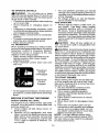
I. GENERAL OPERATION
• Read, understand, and follow all instructions on the machine and in the manual
before starting.
• Do not put hands or feet near rotating
parts or under the machine. Keep clear
of the discharge opening at all times.
- Only allow responsible adults, who are
familiar with the instructions, to operate
the machine.
• Clear the area of objects such as rocks,
toys, wire, etc., which could be picked up
and thrown by the blade.
- Be sure the area is clear of bystanders
before operating. Stop machine if anyone
enters the area.
• Never carry passengers.
- Do not mow in reverse unless absolutely
necessary. Always look down and behind
before and while backing.
• Never direct discharged material toward
anyone. Avoid discharging
material
against awall or obstruction. Material may
ricochet back toward the operator. Stop the
blade when crossing gravel surfaces.
• Do notoperate machinewithoutthe entire
grass catcher, discharge chute, or other
safety devices in place and working.
- Slow down before turning.
• Never leave a running machine unattended. Always turn off blade, set parking brake, stop engine, and remove keys
before dismounting.
- Disengage blade when not mowing. Shut
off engine and wait for all parts to come
to a complete stop before cleaning the
machine, removing the grass catcher, or
unclogging the discharge chute.
- Operate machine only in daylight or good
artificial light.
. Do not operate the machine while under
the influence of alcohol or drugs.
- Watch for traffic when operating near or
crossing roadways.
• Use extra care when loading or unloading
the machine into a trailer or truck.
• Always wear eye protection when operating machine.
• Data indicates that operators, age 60
years and above, are involved in a large
percentage of riding mower-related injuries. These operators should evaluate
their ability to operate the riding mower
safely enough to protect themselves and
others from serious injury.
• Keep machine free of grass, leaves or
other debris build-up which can touch hot
exhaust/engine parts and burn. Do not
allow the mower deck to plow leaves or
other debris which can cause build-up to
occur. Clean any oi! or fuel spillage before
operating or storing the machine. Allow
machine to cool before storage.
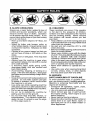
I!. SLOPE OPERATION
Slopes are a major factor related to loss of
control and tip-over accidents, which can
result in severe injury or death. Operation
on all slopes requires extra caution. If you
cannot back upthe slope or if you feel uneasy
on it, do not mow it.
* Mow up and down slopes (15° Max), not
across.
- Watch for holes, ruts, bumps, rocks, or
other hidden objects, Uneven terrain could
overturn the machine. Tail grass can hide
obstacles.
. Choose a low ground speed so that you
will not have to stop or shift while on the
slope.
• Do not mow on wet grass. Tires may lose
traction,
• Always keep the machine in gear when
going down slopes. Do not shift to neutral
and coast downhill.
. If machine stops while going uphill,
disengage blade, shift into reverse and
back down slowly.
- Avoid starting, stopping, or turning on a
slope. Ifthetires lose traction, disengage
the blade and proceed slowly straight down
the slope.
* Keep all movement on the s!opesslow and
gradual. Do not make sudden changes
in speed or direction, which could cause
the machine to roll over.
. Use extra care while operating machine
with grass catchers or other attachments;
they can affect the stability of the machine.
o Do no use on steep slopes.
o Do not try to stabilize the machine by
putting your foot on the ground.
• Do not mow near drop-offs, ditches, or
embankments. The machine could suddenly roll over if a wheel is over the edge
or if the edge caves in.
IlL CHILDREN
Tragic accidents can occur if the operator
is not alert to the presence of children.
Children are often attracted to the machine
and the mowing activity. Never assume
that children will remain where you last
saw them.
• Keep children out of the mowing area and
inthe watchful care of a responsible adult
other than the operator.
• Be alert and turn machine off if a child
enters the area.
° Before and while backing, look behind and
down for small children.
• Never carry children, even with the blade
shut off. They may fall off and be seriously
injured or interfere with safe machine
operation. Children who have been given
rides in the past may suddenly appear in
the mowing areafor another rideand be run
over or backed over by the machine.
• Never allow children to operate the machine.
• Use extra care when approaching blind
corners, shrubs, trees, or other objects
that may block your view of a child.
IV. SERVICE
SAFE HANDLING OF GASOLINE
To avoid personal injury or property damage, use extreme care in handling gasoline,
Gasoline is extremely flammable and the
vapors are explosive.
• Extinguish all cigarettes, cigars, pipes,
and other sources of ignition.
• Use only approved gasoline container.
• Never remove gas cap or add fuel with
the engine running. Allow engine to cool
before refueling.
• Never fuel the machine indoors.
• Never store the machine or fuel container
where there is an open flame, spark, or
pilot light such as on a water heater or
other appliances.
• Never fill containers inside a vehicle or
on a truck or trailer bed with plastic liner.
Always place containers on the ground
away from your vehicle when filling.
• Remove gas-powered equipment from the
truck or trailer and refuel it on the ground.
If this is not possible, then refuel such
equipment with a portable container, rather
than from a gasoline dispenser nozzle.
. Keep the nozzle in contact with the rim
of the fuel tank or container opening at
all times until fueling is complete. Do not
use a nozzle lock-open device.
• lffuelisspi]ledon clothing, changeclothing
immediately.
• Never overfill fuel tank. Replace gas cap
and tighten securely.
GENERAL SERVICE
• Never operate machine in a closed area,
. Keep all nuts and bolts tightto be sure the
equipment is in safe working condition.
• Never tamper with safety devices. Check
their proper operation regularly.
• Keep machine free of grass, leaves, or
otherdebris build-up. Clean oil orfuelspillage and remove any fuel-soaked debris.
Allow machine to cool before storing.
• If you strike a foreign object, stop and
inspect the machine. Repair, if necessary,
before restarting.
. Never make any adjustments or repairs
with the engine running.
• Check grass catcher components and the
discharge chute frequently and replace
with manufacturer's recommended parts,
when necessary.
- Mower blade is sharp. Wrapthe blade or
wear gloves, and use extra caution when
servicing them,
• Check brake operation frequently. Adjust
and service as required.
• Maintain or replace safety and instruction
labels, as necessary.
• Be sure the area is clear of bystanders
before operating. Stop machine if anyone
enters the area.
• Never carry passengers.
• Do not mow in reverse unless absolutely
necessary. Always look down and behind
before and while backing.
CUSTOMER RESPONSIBILITIES
• Read and observe the safety rules,
• Follow a regular schedule in maintaining,
caring for and using your riding mower.
• Follow the instructions under "Maintenance" and "Storage" sections of this
owner's manual.
_.WARNtNG:
This riding mower is
equipped with an internal combustion engine and should not be used on or near any
unimproved forest-covered, brush-covered
or grass-covered land unless the engine's
exhaust system is equipped with a spark
arrester meeting applicable local or state
laws (if any). If a spark arrester is used, it
should be maintained in effective working
order by the operator,
In the state ofCaliforniathe above isrequired
by law (Section4442 of the California Public
Resources Code), Other states may have
similar laws. Federal laws apply on federal
lands. A spark arrester for the muffler is
available through your nearest authorized
service center.
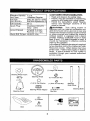
iGaso ine Capacty 1.2 qt.
and Type:
Unleaded Regular
Oil Type
SAE 30 (above 32°F)
API-SG-SL):
SAE 5W-30(below 32°F)
Oil Capacity:
20 oz,
Spark Plug:
Champion RC12YC
(Gap: .030")
Ground Speed
Forward: 0-4 mph
Reverse: 0-1 mph
Blade Bolt Torque: 45-55 Ft. Lbs.
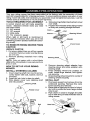
(I) LargeFiatWasher
Steering
Wheel Insert
Steering
Wheel
(1) 1/2-20 Jam Nut
i
(t) Pin
@
0
(1) 5/16-18 Lock Nut
_j_
(1) 5116 Fiat Washer
Steering Shaft
(1) 5/16-18 x 1 1/2
Hex Bolt
Steering Wheel Adapter
Steering
Steering
Shaft Cover
Cover
(1) Washer
i
(2) Key
Seat
Slope
(1) Knob
6
Sheet
Yournewridingmower
hasbeenassembled
atthefactory
withtheexception
ofthose
parts
leftunassembled
forshipping
purposes.
Toensure
safeandproper
operation
ofyour
ridingmower
allpartsandhardware
youassemble
mustbetightened
securely.
Usethe
correct
toolsasnecessary
toinsure
proper
tightness.
TOOLS REQUIRED FOR ASSEMBLY
A socket wrench set will make assembly
easier. Standard wrench sizes you need
are listed below.
(1) 3/4" wrench
(1) 1/2" wrench
(1) Utility knife
(I) Tire pressure gauge
When right or left hand is mentioned in
this manual, it means when you are in the
operating position (seated behind the steering wheel).
TO REMOVE RIDING MOWER FROM
CARTON
UNPACK CARTON
1. Cut along dotted lines on all four panels
of carton, Remove carton and topframe
as one unit,
2. Remove packing materials from riding
mower.
NOTE: Only cut carton with a short blade
utility knife, a long blade or saw can puncture
tires on unit.
4. Slide steedng shaft protective foam cover
over shaft,
5. Position front wheels of the riding mower
so they are pointing straight forward.
HOW TO SET UP YOUR RIDING
MOWER
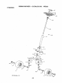
INSTALL STEERING COLUMN
1. Insert steering shaft into mount and securely fasten with bolt, washer, and nut
provided.
2. Insert pin into hole in steering shaft,
3, Slide plastic cover over steering shaft
and into position.
6. Remove steering wheel adapter from
steering wheel and slide adapter onto
steering shaft.
7. Press steering wheel into position on
shaft, install large washer, and tighten
nut securely.
8. Snap steering wheel insert into center of
steering wheel securely.
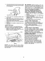
INSTALL SEAT
1. Pivot seat upward and remove from the
cardboard packing, Remove the cardboard packing and discard,
2. Placeseatonseatpan so head ofshoulder bolt is positioned over large slotted
hole in pan.
3. Push down on seat to engage shoulder
bolt in slot and pull seat towards rear of
riding mower.
Shaft
Plastic Cover
Pin
Wheel
,
Foam Cover
SteeringShaft_\\
Seat
Steering
Shaft
Mount
Bolt
4. Pivot seat and pan forward and assemble
adjustment knob and fiat washer _oosely.
Do not tighten.
=O=WARNING: Before starting, read, understand and follow alt instructions in the
Operation section of this manual. Be sure
riding mower is in a well-ventilated area.
Be sure the area in front of riding mower is
clear of other people and objects.
TO ROLL RIDING MOWER OFF
SKID (See Operation section for
location and function of controls)
1, Raise deck lift lever to its highest
position.
2. Release parking brake by depressing
clutch/brake pedal.
3, Engage freewheel control. See "TO
TRANSPORT" in the operation section
of this manual.
4. Roll riding mower forward off skid.
Fiat Washer
5. Lower seat into operating position and
sit in seat.
6. Slide seat until a comfortable position is
reached which allows you to press clutch!
brake pedal all the way down.
7. Get off seat without moving its adjusted
position.
8. Raise seat andtighten adjustment knob
securely.
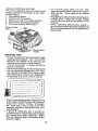
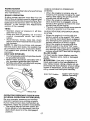
CHECK TIRE PRESSURE
The tires on your riding mower were
overinflated at the factory for shipping purposes, Correct tire pressure is important
for best cutting performance.
• Reduce tire pressure to PSI shown on
tires.
CHECK BATTERY
Make sure battery is securely 1astened,
and that all wires are securely connected.
• Battery is located under the seat.
• Battery has been fully charged from the
factory, before installation.
CHECK DECK LEVELNESS
For best cutting results, mower housing
should be properly leveled. Sea"TO LEVEL
MOWER HOUSING" in the Service and
Adjustments section of this manual.
CHECK FOR PROPER POSITON OF
MOWER DRIVE BELT
See the figure that is shown for replacing
the mower drive belt in the service and
adjustment section of this manual, Verify
that the belt is routed correctly.
CHECK BRAKE SYSTEM
After you learn how to operate your riding mower, check to see that the brake
isoperating properly. See "TO ADJUST
BRAKE" in the Service and Adjustments
section of this manual.
Battery
NOTE: You may now roll your riding
mower off the skid. Follow the appropriate
instruction below to remove the riding mower
from the skid.
8
t//fCHECKLIST
Before you operate your new riding mower,
we wish to assure that you receive the best
performance and satisfaction from this
Quality Product,
Please review the following checklist:.
J All assembly instructions have been
completed.
vz No remaining loose parts in carton,
_/" Battery is properly connected.
vf Seat is adjusted comfortably and tightened securely.
J All tires are properly inflated. (For shipping purposes, thetires were overinflated
at the factory).
v t Be sure mower deck is properly leveled
side-to-side/front-to-rear for best cutting
results. (Tires must be properly inflated
for leveling).
J" Check mower be[t. Be sure it is routed
properly around pulleys and inside all belt
keepers.
J" Check wiring, See that all connections
are still secure and wires are properly
clamped.
J Before driving riding mower, be sure freewheel control is in"transmission engaged"
position (see "TO TRANSPORT" in the
Operation section of this manual).
While learning howto use your riding mower,
pay extra attention to the following important
items:
Engine oil is at proper level.
J Fueltank is fitledwithfresh, clean, regular
unleaded gasoline,
,f Become familiar with all controls, their
location and function. Operate them
before you start the engine.
J Be sure brake system is in safe operating
condition,
if Be sure Operator Presence System and
Reverse Operation System (ROS) are
working properly (See the Operation and
Maintenance sections in this manual).
9
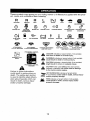
These symbols may appear on your riding mower or in literature supplied with the product. Learn and understand their meaning,
R
N
REVERSE
H
NEUTRAL
L
NIGH
I\1
LOW
CHOKE
SLOW
FAST
IGNITION
ENGINE
OFF
REVERSE
OPERAT[ION
SYSTEM
(ROe)
ENGINE
ON
ENGINE
START
PARKING
TEMP
FUEL
BRAKE
PARKING
LOCKED
,,
OVER
PARKING
BRAKE
OIL PRESSURE
BATTERY
REVERSE
SWITCH
BRAKE
UNLOCKED
÷
FORWARD
MOWER
HEIGHT
MOWER
LIFT
LIGHT
ATTACHMENT
CLUTCH
ENGAGED
ATTACHMENT
CLUTCH
DISENGAGED
DANGER,
KEEP HANDS
AND FEET AWAY
KEEP
AREA
(SEE
CLEAR
SAFETY
SLOPE
RULES
HAZARDS
SECTION)
FREEWREELCONTROL
DANGER
will
result indicates
in death aorhazard
seriouswhich,
Injury.if not avoided,
DISENGAGED
WARNING
hazard
which,
if not avoided,
could resultindicates
in deatha or
serious
iniurY.
BRAK_CLUTCHpEDAL
CAUTION
indicates
a hazard
which, {niury,
if not avoided.
might
resutt
in minor
or moderate
FREEWHEEL
CONTROL
CAUTION a when
indicates
situation
used
that
without
could the
result
alertInsymbol,
damage
to the tractor and!or engine.
ENGAGED
Failure
to follow
could
result
death.
The
instructions
in serious
safety
alert
injury
is used to identify safety information about hazards
which can
result
in death,
and/or
property
serious
damage.
HOT SURFACES indicates a hazard which,
if net avoided, could result in death, serious injury
and/or property damage.
or
symbol
injury
Jl
FIRE indicates a hazard whig.h, i{ not avoided,
could result in death, serious injuw and/or
property damage,
10
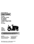
KNOW YOUR RIDING MOWER
READ THIS OWNER'S MANUAL AND SAFETY RULES BEFORE OPERATING
YOUR RIDING MOWER
Compare the illustrations with your riding mower to familiarize yourself with the locations
of various controls and adjustments, Save this manual for future reference.
Parking
Brake
Brake Pedal
Deck Clutch
Lever
Lift
Height
Adj
Our riding mowers conform to the applicable safety standards of the
American National Standards Institute.
DECK CLUTCH LEVER - Used to engage
the mower blade.
BRAKE PEDAL- Used for braking the riding mower and starting the engine.
HEIGHT ADJUSTMENT LEVER - Used to
adjust mower curing height.
IGNITION SWITCH - Used for starting and
stopping the engine.
LIFT LEVER PLUNGER - Used to release
height adjustment lever when changing its
position.
PARKING BRAKE LEVER - Locks parking brake into brake position,
MOTION CONTROL LEVER -SeIects the
speed and direction of the ridingmower.
FREEWHEEL CONTROL - Disengages
transmissionfor pushing or slowlytowing
the ridingmower with the engine off.
ROS "ON" POSITION - Allows operation
of mower deck or other powered attachment while in reverse.
11
The operation of any riding mower can result in foreign objects thrown
into the eyes, which can result in severe eye damage. Always wear
safety glasses or eye shields while operating your riding mower or
performing any adjustments or repairs. We recommend a wide vision
safety mask over spectacles or standard safety glasses.
HOW TO USE YOUR RIDING
MOWER
TO SET PARKING BRAKE
Your riding mower is equipped with an operator presence sensing switch. When engine
is running, any attempt by the operator to
leave the seat without first setting the parking
brake will shut off the engine.
1. Depress brake pedal all the way down
and hold.
2, Depress parking brake lever and release
pressure from brake pedal. Pedal should
remain in brake position. Make sure
parking brake will hold riding mower
secure.
Parking Brake
Motion
Pedal-PushDown
Mower Height
to 'SEn
Lever
Adjustment
"Engaged"
Position
Brake Pedal
"Drive ....
Position
NOTE: .Under certain conditions when riding
mower Jsstanding idlewith the engine running, hot engine exhaust gases may cause
"browning" of grass, To eliminate this possibility, always stop engine when stopping
riding mower on grass areas.
_IbCAUTION: Always stop riding mower
completely, as described above, before
leaving the operator's position.
TO MOVE FORWARD AND BACKWARD
The direction and speed of movement is
controlled by the motion control lever.
1. Start riding mower withclutch/brake pedal
depressed and motion control lever in
neutral (N) position.
2. Move motion control lever to desired
position.
3. Slowly release clutch/brake pedalto start
movement.
IMPORTANT: Bring riding mower to a complete stop before shifting or changing gears.
Failure to do so will shorten the useful life of
your transaxle.
TO ADJUST MOWER CUTTING HEIGHT
The position of the mower height deck lift
lever determines the cutting height.
• Grasp lift lever.
• Press lift lever plunger with thumb and
move lever to desired position.
The cutting height range is approximately
1-1/2 to 4". The heights are measured from
the ground to the blade tip with the engine
not running. These heights are approximate
and may vary depending upon soil conditions, height of grass and types of grass
being mowed.
• The average lawn should be cut to approximately 2-1/2" during the cool season
and to over 3" during hot months. For
healthier and better looking lawns, mow
often and after moderate growth.
• For best cutting performance, grass over
6" in heightshould be mowedtwice. Make
the first cut relatively high; the second to
• desired height.
'Deck Clutch
Lever
"Disengaged"
Position
;lutch
Lever
Engaged"
Position
STOPPING
MOWER BLADE • To stop mower blade, move deck clutch
lever to disengaged position.
GROUND DRIVE• Tostop ground drive, depress brake pedal
all the way down.
ENGINE " Turn ignition keyto"STOP"position and remove key.Always remove keywhen leaving
riding mower to prevent unauthorized use.
IMPORTANT: Leaving the ignition switch in
any position other than "STOP" will cause
the battery to discharge and go dead.
12
TO OPERATE MOWER
Your riding mower is equipped with an
operator presence sensing switch, Any
attempt by the operator to leave the seat
with the engine running and the deck clutch
engaged will shut off the engine. You must
remain fully and centrally positioned in the
seatto preventthe engine from hesitating or
cutting off when operating your equipment
on rough, rolling terrain or hills.
1. Select desired height of cut.
2. Start mower blade by engaging deck
clutch lever.
TO STOP MOWER BLADEDisengage deck clutch lever.
Deck Clutch Lever
"Disengaged" Position
Deck (
Lever
"Engaged ° Position
Mower Height
Adjustment High
Position
Mower Height
Adjustment
Low Position
REVERSE OPERATION SYSTEM (ROS)
Your tractor is equipped with a Reverse
Operation System (ROS). Any attempt by
the operator to travel in the reverse direction with the deck clutch engaged will shut
off the engine unless ignition key is placed
in the ROS "ON" position.
_WARNING:
Backing up with the deck
clutch engaged while mowing is strongly
discouraged. Turning the ROS "ON", to allow reverse operation with the deck clutch
engaged, should only be done when the
operator decides it is necessary to reposition the machine with the attachment
engaged, Do not mow in reverse unless
absolutely necessary.
USING THE REVERSE OPERATION
SYSTEM Only use ff you are certain no children or
other bystanders will enter the mowing
area.
1. Move motion control lever to neutral
(N) position.
2. With engine running, turn ignition key
counterclockwise to ROS "ON" position.
3. Look down and behind before and
while backing.
4. Slowly move motion control lever to
reverse (R) position to start movement.
5. When use of the ROS is no longer
needed, turn the ignition key clockwise
to engine "ON" position.
ROS "ON" Position
_L.CAUTION: Do not operate the mower
without either the entire grass catcher, on
mowers so equipped, or the deflector shield
in place.
\
DeflectorShield
13
Engine "ON" Position
(Normal Operating)
TO OPERATE ON HILLS
•
_ILWARNING:
Do not drive up or down
hills with slopes greater than 15° and do not
drive across any slope. Use the slope guide
at the back of this manual,
• Choose the slowest speed before starting
up or down hills.
• Avoid stopping or changing speed on
hills.
• If stopping is absolutely necessary, push
clutch/brake pedal quicklyto brake position
and engage parking brake.
• Move motion control lever to neutral (N)
position.
• To restart movement, slowly release parking brake and clutch/brake pedal.
• Make all turns slowly.
TO TRANSPORT
When pushing or towing your riding mower,
besure to disengage transmission by placing
freewheel control in freewheel position.
Freewheel control is located at the rear
drawbar of the riding mower.
• Raise mower height adjustment to its
highest position with mower height
adjustment lever,
• Push freewheel control down and over
with foot,
Freewheel
Control
Disengaged
Freewheel
Control
Engaged
• Toreengage transmission, reverse above
procedure, or press brake Iever allthe way
down,
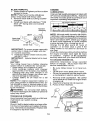
BEFORE STARTING THE ENGINE
CHECK ENGINE OIL LEVEL
The engine in your riding mower has been
shipped, from the factory, already filled with
summer weight oil.
1. Check engine oil with riding mower on
level ground.
2. Remove oil fill cap/dipstick and wipe
clean, reinsert the dipstick and screw cap
tight, wait for a few seconds, remove and
read oil level. If necessary, add oil until
"FULE' mark on dipstick is reached. Do
not overfill.
14
For cold weather operation you should
change oil for easier starting (See the oil
viscosity chartin the Maintenance section
of this manual).
• To change engine oil, see the Maintenance section in this manual.
ADD GASOMNE
• Fill fuel tank to bottom of filler neck. Do
not overfill. Use fresh, clean, regular
unleaded gasoline with a minimum of
87 octane. (Use of leaded gasoline will
increase carbon and lead oxide deposits
and reducevalve life). Do not mixoil with
gasoline. Purchase fuel in quantities that
can be used within 30 days to assure fuel
freshness.
,_CAUTION:
Wipe off any spilled oil or
fuel. Do not store, spill or use gasoline near
an open flame.
_t, OAUTION: Alcohol blended fuels (called
gasohol or using ethanol or methanol) can
attract moisture which leads to separation
and formation of acids during storage, Acidic
gas can damage the fuelsystem of an engine
while in storage. To avoid engine problems,
the fuel system should be emptied before
storage of 30 days or longer. Drain the gas
tank, start the engine and let it run until the
fuel lines and carburetor are empty, Usefresh
fuel next season. See Storage Instructions
for additional information. Never use engine
or carburetor cleaner products inthe fueltank
or permanent damage may occur.
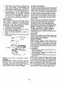
TO START ENGINE
When starting the engine for the first time
or if the engine has run out of fuel, it will
take extra cranking time to move fuel from
the tank to the engine.
1. Be sure freewheel control is in the
transmission engaged position.
2, Sit on seat in operating position,
depress clutch/brake pedal and set
parking brake,
3. Place motion control lever in neutral
(N) position,
4, Move deck clutch to disengaged position.
5. Insert key into ignition and turn key
clockwise to start position and release
key as soon as engine starts, Do not
run starter continuously for more than
fifteen seconds per minute,
NOTE: If at high altitude (above 3000
feet) or in cold temperature (below 32°F)
the fuel mixture may need to be adjusted
for best performance.
RECOIL
STARTING
SYSTEM
Thisunitisequipped
withanengine
recoil
starting
system.
Ifthebattery
istooweak
tostartengine,
1. Setparking
Brake.
2. TurnkeytoONposition.
3. Make
sureunitisinneutral
position.
4, Setdecktodisengaged
position.
5. Pullrecoilcordtostartengine.
Gasoline Fi!ler
_Recoil Starter
Handle
MOWING TIPS
• Mowershould be properly leveledfor best
mowing performance. See "TO LEVEL
MOWER HOUSING" in the Service and
Adjustments section of this manual,
• The left hand side of mower should be
used for trimming,
Drive so thatclippings are discharged onto
the area that has already been cut. Have
the cutareato the right of the riding mower.
This will result in a more even distribution
of clippings and more uniform cutting.
f
• When mowing large areas, start byturning
to the right so that clippings wilt discharge
away from shrubs, fences, driveways,
etc. After one or two rounds, mow in the
opposite direction making left hand turns
until finished.
• If grass is extremely tall, it should be
mowed twice to reduce load and possible
fire hazard from dried clippings, Make
first cut relatively high; the second to the
desired height.
15
• Do not mow grass when it is wet. Wet
grass will plug mower and leave undesirable clumps. Allow grass to dry before
mowing.
• Regulate ground speed by selecting a low
enough gear to give the mower cutting
performance as well as the quality of cut
desired.
• When operating attachments, select a
ground speed that wilt suit the terrain and
give best performance of the attachment
being used.
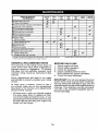
MAINTENANCE
BEFORE eVERY
SCHEDULE
i/,,
R
_cvI
e
USE
i
HOURIS
EVERY
2_
HOURS
EVEIIV
EVERY
HOURS
HOURS
5e
EVERY
1oo
aE_ORE
s_so. s_nARE
i
c heok,,<B_ake,<Ope
ration
Check
Tire Pressure
'if
If
V
V'
..............
D Choo.
Opora,orP
....... &.ess_,_ms _, ii,."...............
NI
Check for Loose Fasteners
G
ChecklReplaee
Clean
E
R
Battery
if
t_'
Mower Blade
and
tl d
Lubricate Axles ;_nd Spindles
i_
Ch_kTrau;_'×J_
cooIi_g
i/
Check
Mower
Check
V+Selt
0ii
Drive
Cheek
Change
N
cIP.arl
.......
.................................
if
0il Level
_
.........
2. SIt_fCt
morl_
Spark
Ill##
libel
;;; .....
I/
V'
PltJ@
Air Filler
olten
"
...... V_,I
FTIter
E ,,,C!_,anE,G,cti,ne
Coolie!f! Fine
I - Oh_nglt
"
i f#
N
I ,!,n,_e_c!
M..i_r_Spark
Arrester
ReI:,lace
"
V _
GDice°Air
so,ODD
Replace
t/
V"
IEn_line 011
Air
If
Levelness
Chains
IEel_ne
E
V
I_
Termirials
.....................
V
P,a,per, C,a_tr!dge
when
moftt _fltln wh_
opettttr@
U_tlr
if
V_.
t
I_lttvt'
load
or
ff_ high
arable
_l lempe_li_lls.
3 - i_pla;e
blade
n_ re _ften
.............
when
mowing
in slln_fy
ll}l.
oil _aling it_ I_irty _r dully c_dil_ns.
GENERAL RECOMMENDATIONS
The warranty on this riding mower does not
cover items that have been subjected to
operator abuse or negligence. To receive
full value from the warranty', operator must
maintain riding mower as instructed in this
manual.
Some adjustments will need to be made
periodically to properly maintain your riding
mower.
BEFORE EACH USE
1. Check engine oil level.
2. Check brake operation.
3. Check tire pressure.
4. Check operator presence and
ROS systems for proper operation.
5. Check for loose fasteners.
IMPORTANT: Do not oil or grease the pivot
points which have special nylon bearings.
Viscous lubricants will attract dust and dirt
that will shorten the life of the self-lubricating
bearings. If you feel they must be lubricated,
use only a dry, powdered graphite type lubricant sparingly.
At least once a season, check to see if
you should make any of the adjustments
described in the Service and Adjustments
section of this manual.
• At least once a year you should replace
the spark plug, clean or replace air filter,
and check blade and belt for wear. A new
spark plug and clean air filter assure proper
air-fuel mixture and help your engine run
better and last longer.
16
RIDING MOWER
Always observe safety ruleswhenperforming
any maintenance.
BRAKE OPERATION
if riding mower requires more than four (4)
feet to stop at highest speed in highest gear
on a level, dry concrete or paved surface, then
brake must be serviced. (See "TO ADJUST
BRAKE" in the Service and Adjustments
section of this manual).
TIRES
• Maintain proper air pressure in all tires
(See PSI on tires).
• Keep tires free of gasoline, oil, or insect
control chemicals which can harm
rubber.
• Avoid stumps, stones, deep ruts, sharp
objects and other hazards that may cause
tire damage.
NOTE: To seal tire punctures and prevent
fiat tires due to stow leaks, tire sealant may
be purchased from your local parts dealer.
Tire sealant also prevents tire dry rot and
corrosion.
AXLE AND SPINDLES
• Frontwheelaxlesandfrontspindlesshould
be properly lubricated.
° Wheel Axles should be lubricated with a
dry, powdered graphite type lubricant.
• Spindles should be lubricatedwith aspray
type silicone base lubricant.
CHECK OPERATOR PRESENCE
SYSTEM
* When the engine is running, any attempt by the operator to leave the seat
without first setting the parking brake
should shut off the engine.
• When the engine is running and the
deck clutch lever is engaged, any attempt by the operator to leave the seat
should shut off the engine.
. The deck clutch lever should never operate
unless the operator is in the seat.
CHECK REVERSE OPERATION (ROS)
SYSTEM
• When the engine is running with the
ignition switch in the engine "ON" position and the deck clutch lever engaged,
any attempt by the operator to shift into
reverse should shut off the engine.
• When the engine is running with the
ignitionswitch in the ROS "ON" position and the deck clutch lever engaged,
any attempt by the operator to shift into
reverse should NOT shut off the engine.
BLADE CARE
For best results mower blades must be
sharp. Replace worn, bent or damaged
blades.
CAUTION: Use only a replacement
blade approved by the manufacturer of
your ridingmower, Using a blade not approved by the manufacturer of your riding
mower is hazardous, could damage your
riding mower and void yourwarranty.
ROS "ON" Position
OPERATOR PRESENCE SYSTEM AND
REVERSE OPERATION SYSTEM (ROS)
Be sure operator presence and reverse
operation systems are working properly.
If your riding mower does not function as
described, repair the problem immediately.
• The engine should not start unless the
brake pedal is fully depressed, and the
deck clutch lever is in the disengaged
position.
17
Engine "ON" Position
(Normal Operating)
BLADE REMOVAL
1. Raise mower to highest position to allow
access to blade.
NOTE: Protect your hands with gloves
and/or wrap blade with heavy cloth.
2. Remove blade bolt by turning counterclockwise,
3. Install new blade with stamped "THIS
SIDE UP" facing deck and mandrel
assembly.
ENGINE
LUBRICATION
Only use high quality detergent oil rated with
API service classification SG-SL. Selectthe
oil's SAE viscosity grade according to your
expected operating temperature.
Mandrel
Assembly
Blade Bolt
._,,_
AL¢_.__Z_f_J/
IMPORTANT: To ensure proper assembly,
center hole in blade must align with star
on mandrel assembly.
4, Install and tighten blade bolt securely
(45-55 Ft. Lbs.).
IMPORTANT: Special blade bolt is heat
treated,
BATTERY
Your riding mower has a battery charging
system which is sufficient for normal use.
. Keep battery and connectors clean.
• Only recharge battery with charger
approved for a 12V 2.8 amp. hour battery.
• Charging with any other charger or an
automotive style charger can cause permanent damage to the battery.
• Charge battery for 24 hours for a full
charge,
NOTE: The original equipment battery on
your riding mower is maintenance free. Do
not attempt to open or remove caps or covers, Adding or checking level of electrolyte
is not necessary,
_kWARNING:
Do not jump start battery.
Permanent damage to the battery or personal
injury may occur.
TRANSAXLE COOLING
Keep transaxle free from build-up of dirt and
chaff which can restrict cooling.
V-BELT
Check V-belt for deterioration and wear after
100 hours of operation and replace if necessary. The belt isnot adjustable. Replace belt
if it begins to slip from wear.
NOTE: Although multi-viscosity oils (5W30,
10W30 etc.) improve starting in coldweather,
the oils willresult inincreased oil cons umption
when used above 32°F. Check your engine
oil level more frequently to avoid possible
engine damage from running low on oil.
Change the oil after every 25 hours of
operation or at least once a year if the
riding mower is not used for 25 hours in
one year.
Check the crankcase oil level before starting
the engine and after each eight (8) hours
of operation. Tighten oil fill cap/dipstick
securely each time you check the oil level.
TO CHANGE ENGINE OIL
Determine temperature range expected
before oil change. All oil must meet API
service classification SG-SL
•
•
•
Be sure riding mower is on level surface,
Oil wilt drain more freely when warm.
Oil can be pumped from the engine with
a mechanical or electric siphon pump.
1. Remove oil fill cap!dipstick. Be careful
not to allow dirt to enter the engine when
changing oil.
2. Insert end of pump into oil reservoir,
3. Pump oil from reservoir.
Oil Cap
Oil Fill
18
4. Refill engine with oilthrough oil fill dipstick
tube. Pour slowly. Do not overfill, For
approximate capacity see "PRODUCT
SPECIFICATIONS"section ofthis manual
5. Use gauge on oil fill cap/dipstick for
checking level, For accurate reading,
tighten dipstick cap securely onto the
tube before removing dipstick. Keep oil
at "FULL' line on dipstick. Tighten cap
onto the tube securely when finished.
AIR FILTER
Your engine will not run properly us[ng a
dirty air filter. Replace the air filter every
100 hours of operation or every season,
whichever occurs first. Service air cleaner
more often under dusty conditions.
1. Remove cover knob and cover.
2. Carefully remove cartridge.
3. Clean base carefully to prevent debris
from falling into carburetor.
4. Clean by gently tapping on a flat surface.
5, Reinstall cartridge, cover and securewith
cover knob.
_r_...l._
Cover Knob
Cover
Air Filter
NOTE: If very dirty or damaged, replace
cartridge.
IMPORTANT: Petroleum solvents, such as
kerosene, are not to be used to clean the
cartridge, They may cause deterioration of
the cartridge. Do not oil cartridge. Do not
use pressurized air to clean cartridge.
19
CLEAN AIR SCREEN
Air screen must be kept free of dirt and chaff
to prevent engine damage from overheating.
Clean with a wire brush or compressed airto
remove dirt and stubborn dried gum fibers,
CLEAN AIR INTAKEiCOOMNG AREAS
To ensure proper cooring, make sure the
grass screen, cooling fins, and other external surfaces of the engine are kept clean
at all times.
Every 100 hours of operation (more often
under extremely dusty, dirty conditions),
remove the blower housing and other
cooling shrouds, Clean the cooling fins
and external surfaces as necessary. Make
sure the cooling shrouds are reinstalled.
NOTE: Operating the engine with a
blocked grass screen, dirty or plugged
cooling fins, and/or cooling shrouds
removed will cause engine damage due to
overheating.
MUFFLER
Inspect and replace corroded muffler and
spark arrester (if equipped) as it could create
a fire hazard and/or damage.
SPARK PLUG(S)
Replace spark plug(s) at the beginning of
each mowing season or after every 100
hours of operation, whichever occurs first.
Spark plug type and gap setting are shown
in 'PRODUCT SPECIFICATIONS" section
of this manual.
CLEANING
• Clean engine, battery, seat, finish, etc. of
all foreign matter.
• Keep finished surfaces and wheels free
of all gasoline, oil, etc,
• Protect painted surfaces with automotive
type wax.
We do not recommend using a garden hose
or pressure washer to clean your riding
mower unless the engine and transmission
are covered to keep water out. Water in engine or transmission will shorten the useful
life of your riding mower. Use compressed
air or a leaf blower to remove grass, leaves
and trash from riding mower and mower.
_
SERVICE
ARNING:ORTO
ADJUSTMENTS:
AVOID SERIOUS INJURY, BEFORE PERFORMING ANY
I. Depress clutch!brake pedal fully and set parking brake.
2, Place motion control lever in neutral (N) position.
3. Place deck clutch in "DISENGAGED" position.
4. Turn ignition key to "STOP" and remove key.
5. Make sure the blade and all moving parts have completely stopped.
6, Disconnect spark plug wire from spark plug and place wire where it cannot
come in contact with plug:
RIDING MOWER
TO REMOVE MOWER
1, Place deck clutch in "DISENGAGED"
position.
2. Move mower height adjustment lift lever
forward to lower mower to its lowest
position.
3. Remove mandrel cover.
4. Remove pins holding left and right front
mower suspension arms in place,
5. Remove bolt holding deck front to rear
leveling rod in place.
6. Remove pin holding deck lift link arm in
place.
7, Remove bolt holding deck side to side
leveling rod in place.
8. Remove belt from around pulleys.
9. Slidedeckoutfrom undersideofmower.
TO INSTALL MOWER
Install in reverse order following instructions
in "TO REMOVE MOWER" section.
Deck Leveling
Side to Side
Rod Bolt
Mandrel
Cover
Front Leveling
Rod Bolt_
Deck Lift
Link Pin
Mower
Suspension
Arm Pin
20
TO LEVEL MOWER HOUSING
Adjust the mower while riding mower is
.parked on level ground or driveway. Make
sure tires are properly inflated (See side
of tire for proper PSI), if tires are over or
underinfiated, you will not properly adjust
your mower,
SIDE-TO-SIDE ADJUSTMENT
• Raise mower to its highest position.
• Measure distance "A" from bottom edge
of mower to ground level at front corners
of mower.
• Toraise the right side of the mower, tighten
lift link adjustment nut.
• Tolower the right side ofthe mower, !oosen
lift link adjustment nut,
NOTE: Each ful!turn of adjustment nut will
change mower height about 3/16".
BottomEdgeof
Mowerto Ground
Nut "G"
Nut "H"
Trunnion
BottomEdgeof
Mowerto Ground
I.t L! ................
tl !!ltf,,
• Recheck measurements after adjusting.
FRONT-TO-BACK ADJUSTMENT
IMPORTANT: Deck must be level side-to
side.
To obtain the best cutting results, the mower
housing should be adjusted sothatthefront is
approximately 1/8"to 1/2" lower than the rear
when the mower is in its highest position,
Check adjustment on right side of riding
mower, Measure distance"F" directly in front
and behind the mandrel at bottom edge of
mower housing as shown.
• To lower front of mower housing turn nuts
"G" and "H" clockwise.
• When distance "F" is 1/8" to 1/2" lower
at front than rear, tighten nut "H" against
trunnion on front link.
• To raise front of mower housing turn nuts
"G" and "H" counter clockwise.
- When distance "F" is 1/8" to 1/2" lower
at front than rear, tighten nut "H" against
trunnion on front link.
NOTE: Each full turn of "G" will change "F"
TO REPLACE MOWER BLADE DRWE
BELT
MOWER DRIVE BELT REMOVAL
1. Park ridingmower on a level surface.
2, Set parking brake.
3. Lower mower to its lowest position,
4, Remove mandrel cover from mower
deck.
5. Remove rear engine plate from unit.
6. Remove rear belt keeper from unit,
7. Carefully roll belt over the top of the
mower blade mandrel,
8. Remove belt from idler pulleys.
9. Check idler pulleysto seethatthey rotate
freely,
10, Remove belt from rear drive pulley.
MOWER DRIVE BELT INSTALLATION
Install in reverse order following instructions in "MOWER DRIVE BELT REMOVAL"
section.
by approximately about 8/8",
Recheck side-to-side adjustment,
21
TO ADJUST BRAKE
Your riding mower is equipped with an
adjustable brake system which is mounted
on the right side of the transaxle. If riding
mower requires more than (4) feet stopping distance in highest gear on a lever dry
concrete or paved surface, then brake must
be adjusted.
1. Park riding mower on a level surface.
2. Release brake/parking pedal.
3. Measure distance between rotor and
brake pad if distance between rotor and
brake pad is more than .02" gap brake
needs to be adjusted.
4. Tighten caliper nut until .02" gap is
reached.
REAR WHEEL
1. Block up Rear axle securely.
2. Remove dust cover, retaining ring,washer, and square key while pulling tire off.
3. Repair tire and reassemble.
4. Replace square keywhite puttingtire back
on, then replacewasher and retaining ring
securely in axle groove ,when pushing
tire back onto shaft reach under and pull
chain sprocket toward you to ease tire
replacement.
NOTE: To seal tire punctures and prevent
flat tires due to slow leaks, purchase and
use tire sealant, Tire sealant also prevents
tire dry rot and corrosion,
Rotor
Washer
Retaining
Ring_
Pad
Dust
Nut
NOTE: Feeler gauge may be necessary
get correct measurement,
Cover
, Square Key
(rear wheel only)
TO START ENGINE WITH A WEAK
BATTERY
to
TO ADJUST STEERING WHEEL
ALIGNMENT
Ifsteering wheel crossbars are not horizontal
(left to right) when wheels are positioned
straight forward, move steering wheel
and reassemble per instructions in the
"INSTALL STEERING COLUMN"section of
this manual,
TO REMOVE WHEEL FOR REPAIRS
FRONT WHEEL
1. Block up front axle securely.
2. Remove dust cover, retaining ring, and
washer to allow wheel removal.
3. Repair tire and reassemble.
4. Replace washer and retaining ring
securely in axle groove.
_,CAUTION:
Lead-acid batteries generate explosive gases. Keep sparks, flame
and smoking materials away from batteries.
Always wear eye protection when around
batteries.
If your battery is too weak to start the engine,
it should be recharged. (See "BATFERY" in
the Maintenance section of this manual).
NOTE: This unit is equipped with an engine
recoil starting system that can be used if the
battery is too weak to start. See "RECOIL
STARTING SYSTEM" in operation section
of this manual.
REPLACING BATTERY
_IbWARNING: Do not short battery terminals by allowing awrench or anyother object
to contact both terminals at the same time.
Before connecting battery, remove metal
bracelets, wristwatch bands, rings, etc.
Positive terminal must be connected
first to prevent sparking from accidental
grounding,
22
1. Liftseatforboltaccess.
ENGINE
2. Disconnect
BLACK
battery
cablethen Your engine speed has beenfactory set. Do
RED
battery
cable.
not attempt to increase engine speed or it
3, Remove
battery
bracket
bolt.
may result in personal injury, If you believe
4. Install
newbattery
withterminals
facing that the engine is running too fast or too slow,
totheright,andaway
from seat as
take your riding mower to a qualified service
shown,
5. Reinstall battery bracket and bolt.
6. First connect RED battery cable to positive (+) battery terminal.
7. Connect BLACK grounding cable to
negative (-) battery terminal
Fender
center for repair and/or adjustment.
Your carburetor is not adjustable. If your
engine does not operate properly due to
suspected carburetor problems, take your
riding mower to a qualified service center
for repair and/or adjustment.
IMPORTANT: Never tamper withthe engine
governor, which isfactory set for proper enginespeed. Overspeeding the engine above
the factory high speed setting can bedangerous. If you think the engine-governed high
speed needs adjusting, contact a qualified
service center, which has proper equipment
and experience to make any necessary
adjustments,
Battery
Battery
Bracket
INTERLOCKS AND RELAYS
Loose or damaged wiring may cause your
riding mower to run poorly, stop running, or
prevent it from starting.
• Check wiring, Make sure all wiring and
connectors are secure.
TO REPLACE FUSE
Replace with 4 amp, or 5 amp. automotive
type plug-in fuse. The fuse holderis located
underthe fender.
23
Immediately prepare your riding mower for
storage at the end of the season or if the
riding mower will not be used for 30 days
or more,
,_WARNING: Neverstorethe riding mower
with gasoline in the tank inside a building
where fumes may reach an open flame or
spark. Allowthe engine to cool before storing
in any enclosure.
MOWER
Remove deck from mower for winter storage. When mower is to be stored for a
period of time, clean it thoroughly, remove
all dirt, grease, leaves, etc. Store in a clean,
dry area.
1. Clean entire riding mower (See"CLEANING" in the Maintenance section of this
manual),
2. Inspect and replace belt, if necessary
(See belt replacement instructions in the
Service and Adjustments section of this
manual).
3. Lubricate as shown in the Maintenance
section of this manual.
4. Be sure that all nuts, bolts and screws
are securely fastened. Inspect moving
parts for damage, breakage and wear.
Replace if necessary.
5. Touch up all rusted or chipped paint
surfaces; sand lightly before painting.
BATTERY
- Fully charge the battery for storage.
- If battery is removed from riding mower
for storage, do not store battery directly
on concrete or damp surfaces,
ENGINE
FUEL SYSTEM
IMPORTANT: It is important to prevent
gum deposits from forming in essential fuel
system parts such as carburetor, fuel hose,
or tank during storage. Also, alcohol blended
fuels (called gasohol or using ethanol or
methanol) can attract moisture which leads
to separation and formation of acids during
storage. Acidic gas can damage the fuel
system of an engine while in storage.
24
• Empty the fuel tank by starting the engine
and letting it run until the fuel lines and
carburetor are empty.
• Never use engine or carburetor cleaner
products in the fuel tank or permanent
damage may occur.
• Use fresh fuel next season.
NOTE: Fuel stabilizer is an acceptable alternative in minimizing the formation of fuel
gum deposits during storage. Add stabilizer
to gasoline in fuel tank or storage container.
Always follow the mix ratiofound on stabilizer
container. Run engine at least 10 minutes
after adding stabilizer to allowthe stabilizer to
reach the carburetor. Do not empty the gas
tank and carburetor if using fuel stabilizer.
ENGINE OIL
Drain oil (with engine warm) and replace
with clean engine oil. (See "ENGINE" in the
Maintenance section of this manual).
CYLINDER(S)
1. Remove spark plug(s).
2. Pour one ounce of oil through spark plug
hole(s) into cylinder(s).
3. Turn ignition key to "START" position for
a few seconds to distribute oil,
4, Replace with new spark plug(s).
OTHER
• Do not store gasoline from one season to
another.
• Replaceyour gasoline can ifyour can starts
to rust. Rust and/or dirt in your gasoline
will cause problems.
• If possible, store your riding mowerindoors
and cover it to give protection from dust
and dirt.
• Cover your riding mower with a suitable
protective cover thatdoes not retain moisture. Do not use plastic. Plastic cannot
breathe which allows condensation toform
and will cause your riding mower to rust,
IMPORTANT: Never cover riding mower
while engine and exhaust areas are still
warm.
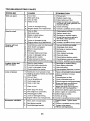
TROUBLESHOOTING
CHART:
PROBLEM
CAUSE
,,,,,,,,
Will not start
1
Out of fiJel,
1
Fill fuel tank.
2
3
Bad spark plug,
Dirty air filter.
2
3
Replace spark plug.
Clean/replace air filter.
4
Water in fuel.
4
Empty fuel tank and carburetor,
refill tank with fresh gasoline and
replace fuel filter.
5
Check all wiring.
Loose or damaged
6
Engine valves out of adjustment.
6
Contact a qualified service center
1
Dirty airfitter.
1
Clearqreplace
2.
Bad spark plug.
2
Replace spark plug.
Weak or dead battery.
3
Recharge or replace battery.
4
Empty fuel tank and refill tank
with fresh, clean gasoline,
5
6
Check all wiring,
Contact a qualified service center,
4
Engine clicks
will not start
but
Loss of power
Loose or damaged wiring.
Engine valves out of adjustment.
1
Clutch/brake pedal noi depressed,
1
Depress clut'ch!brake pedai.
2
Deck clutch is engaged,
2
Disengage
3
4
Weak or dead battery.
Blown fuse.
3 , Recharge or replace
4 RepJace fuse.
5
Corroded battery terminals.
5
Ciean battery terminals.
6
Loose or damaged widng,
6
Check all wiring.
7
8
Faulty ignition switch,
Faulty solenoid or starter.
7
8
Checl<,lreplace ignition switch,
Check/replace solenoid or starter.
9
Faultyoperatorpresenceswitch{es).
9
Contact a qualified service center,
1 Weak
ordead
ba ,ry.
deck clutch.
battery,
.....
i Recharge
orrepSase
battery.
2
Corroded battery terminals;
2
Clean battery terminals.
3
Loose or damaged wiring,
3
Check all wiring,
4
Faulty solenoid or starter.
4
Check/replace
1
2
'Cutting too much grass/too fast.
Build-up of grass, leaves and trasl"
under mower,
1
2
Raise cutting height/reduce
Clean underside of mower
housing.
3
Clean/replace
4
vibration
' Stale or dirty fueL
air filter.
5
6
3
Excessive
wiring,
"
5
3
Engi'ne will not
turn over
CORRECTION
Dirty air filter.
_Low oil level/dirty
oil
5
6
Faulty spark plug.
Stale or dirty fuel.
7
Water in fuel.
8
Spark plug wire loose.
solenoid or starter.
speed.
air filter,
4
Check oit level/change
5
6
Clean®aporchangesparkplug
Empty fuel tank and refill tank
wth fresh, clean gasoline.
Empty fuel tank and carburetor,
refill tank with fresh gasoline.
7
8
oil.
Connect & tighten spark plug wire
9
10
Dirty engine air screen/fins.
Dirty/clogged muffler.
9
10
Clean engine air screen/fins.
Clean!repface muffler,
11
Loose or damaged wiring.
11
Check atl wiring.
12
Engine valves out of adjustment.
12
Contact a qualified service center.
1
Worn, bent or loose blade,
1
Replace blade, Tighten blade
bolt.
2
Bent blade mandrel.
2
Contact
3
Loose/damaged part(s).
3
Tighten loose
Replace
damaged
part(s),
parts,
25
a qualified service center,
TROUBLESHOOTING
CHART:
PROBLEM
CAUSE
Engine continues
to
run when operator
leaves seat with attachment clutch engaged
1
Faulty operator-safety
control system.
Poor cut - uneven
cutting
1
2
Wow, bent or loose blade.
Mower deck not level.
3
Buildup of grass, leaves, and trash
under mower.
4
Bent blade mandrel.
CORRECTION
presence
Check wiring, switches and
connections. If not corrected,
contact a qualified service center,
1
Replace blade,'Ti'ghien
blade boll
2
3
Level mower deck,
4
Ciean underside of mower
housing.
Contact a qualified service center
Clean around mandrels to
open vent holes.
5
Clogged mower deck vent from
i build-up of grass, eaves, and
trash around mandrel.
5
1
2
Obstruction
1
2
Remove obstruction.
3
Frozen
3
Replace idler pulley.
4
Contact a qualified service center.
1
shi.tos,ower
Wet grass.
2
Mower deck not level.
3
AUow grass to dry before mowing
Level mower deck,
4
5
Low/uneven tire air pressure,
Worn, bent or loose blade.
4
6
Buildup of grass, leaves and
trash under mower_
7
Mower drive belt worn,
7
Replace mower drive belt.
8
Blade improperly installed.
Improper blade used.
B
9
Reinstall blade sharp edge down,
Replace with blade listed in
this manual.
Clean around mandrels to
open vent holes,
,,,,,,,
Mower blade will
not rotate
Poor grass
discharge
Loss
of drive
Engine dies when
tractor is shifted
into reverse
mower
drive belt
idler pulley.
Frozen btade mandrel,
1
2
Travel speed too fast.
9
will not
Worn/damaged
4
_3
Battery
charge
in clutch mechanism.
................
5
Replace mower drive belt,
Check tires for proper PSI.
Replace/sharpen
blade. Tighten
blade bolt,
Clean underside of mower
housing.
10
10
Clogged mower deck vent holes
from buildup of grass, leaves, and
trash around mandrels.
I
2
Bad battery ceil(s).
Poor cabie connections.
1
2
Replace battery.
Check/clean all connections,
3
Faulty alternator.
3
Replace alternator.
1
Freewheel control in
"DISENGAGED" position.
1
2
Axle key missing,
2
Place freewheel control in
"ENGAGED" position,
Install axle key at rear wheel. See
"TO REMOVE WHEEL" in the
Service and Adjustments section.
1
Reverse operation system (ROS)
is not "ON" while mower or other
attachment is engaged.
26
1"
Turn ignition key to Ros "ON"
position. See Operation section.
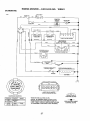
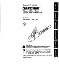
RIDING MOWER--CATALOG
NO. WE261
SCHEMATIC
A
_
ISNIT|ON !
,JSIT _
^
SPAR_PLUG
GAP
,p
,
DIODE
,.............
STATOR
._
X
_AFETY START MODUL_
VIEWED FI_OM IV',_TI_G SIDE
IGNITION SWITCH
POSITION
C|RCUIT
OFF
M+C-+A1
RIYd
STAKT
B+AI
"MAY-.R'
L+A2
--<>-REMOVABLE
CONNECTIONS
WIRING INSULATED CLIPS
NOTE: IDWlRINGINSULATED
CLIPS
WEPJ_ REMOVED FOR SERVICING OF
UNIT, THEY SHOULD BE RE-INSTALLED
TO PROPERLY SECURE YOUR WIRING.
B+S÷AI
27
@
NON-REMOVABLE
CONNECTIONS
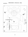
RIDING
MOWER - -CATALOG NO.
WE261
ELECTRICAL
LRV1
5
11
r
10
!
9
/
7
28
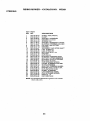
ELECTRICAL
RIDING MOWER - .CATALOG NO. WE261
KEY
PART
NO.
NO.
1
532
2
,3
4
532 42 54.16
532 19 33-50
532 41 19-33
FOAM, POLYURETHANE
SWITCH,
IGN, DLTA, P-IN, ROS
KE_ MOLDED
ENGLISH/SPAN[SH
5"
532
532
532
532
532
532
532
532
532
532
KL:_, MOLDED
ENGLISH/FRENCH/INTERNATIONAL
FUSE, 5A
FUSE, 40A
SWITCH,
PLUNGER,
NO, OLIVE
RELAY, 40A
SWITCH,
INTLK,CL,
MWR, GRY
SWITCH,
INTERLOCK,
NONC,GRAY
MODULE,
STARTING,
RECOIL,
LRV
SWITCH,
SEAT, DR ROS
HARNESSt
IGN, ELECTSTART,
LRV
6
7
8
9
10
11
12
13
DESCRIPTION
43 70-70
41 19-35
43 33-80
42 59-37
t6 07-84
43 15,-42
10 95-53
_7 61-38
,$:3t8-46
19 27-49
42 84.77
BATTERY
NOTE: All component dimensions given in U.S. inches
t inch = 25,4 mm
29
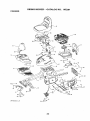
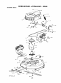
CHASSIS
RIDING
MOWER
- -CATALOG NO.
3O
WE261
RIDING MOWER--CATALOG
NO, WE261
CHASSIS
KEY
PART
NO.
NO.
1
532 42 80-,48
WELDMENT,
2
8
4
5
6
7
8
9
10
11
I2
13
14
15
16
17
532
532
532
532
632
582
532
532
532
532
832
532
532
532
532
532
42
42
42
42
42
42
42
42
19
17
40
43
42
42
43
42
SUPPORT,
AXEL LH
SUPPORT,
AXEL RH
SHIELD.
TRANSAXLE
FRONT
BRACE, AXLE CROSS
COVER,
FRICTION
DRIVE
PLATE, ENGINE
BRACKET,
CHASSIS
FRONT
BRACKET, STEERING
SUPPORT
PAN, SEAT
BRACKET, SWITCH
MOUNTING
BOOT, DUST
COVER, FOOT REST
STRUCTURE,
FOOT REST
SUPPORT,
FOOT REST
FENDER,
CONTROL
GUARD.
ENGINE
t8
- *19
532
582
632
532
42 80-47
43 23-89
4356-74
42 89-86
ENGINE,
ENGINE,
ENGINE,
KEEPER.
20
21
22
23
532
832
582
532
42
42
42
14
80-46
98-15
88-26
98-46
BRACKET', BA'N'ERY
LEVER, SWITCH
DECK CLUTCH ASM
KNOB
24
28
26
27
26
29
80
532
872
878
532
532
532
$82
41
14
5t
43
42
43
43
63-58
04-24
04-00
00-87
83-0t
08-I7
04-70
SCREW,
NO. I0
BOLT, CARRIAGE
1/,,4-20 X 3
NUT, 1/,4-20
SPACER,
ENGINE
DISC, FRICTION
ASM
BOLT, SCKT HD 3/8-24 X 1,25
BEARING
8I
82
33
34
532
882
532
532
43
15
12
12
04-69
04-06
41-81
12-50
SPACER,
NEUTRAL
BOLT, 3/,8-t6 X .280
SPRING,
SEAT
SPRING
,35
36
37
38
39
40
41
42
43
44
872
532
819
532
532
582
582
532
873
582
05
12
17
16
13
12
12
17
80
42
04-12
70-18
19-12
6B-69
43-00
t2-48
39-76
18-52
05-00
82-48
BOLT, 1/,4-20 X 1 1/2
BOLT, SHOULDER
WASHER,
17/32 X 1 3/,16
KNOB, SEAT
SPACER
BUSHING,
NYLON SNAP
NUT, LOCK
BOLT, 6/16-18 SHOULDER
NUT, 5/,16-t8
SEAT
46
46
47
817 00 05-12
817 49 06°08
582 08 67-77
BOLT, 5/,16-18
BOLT, 5/16-18
SCREW
48
49
50
632 40 89-81
8t 7 06 05-16
532 16 54-92
BEARING,
FLANGE,
BALL
SCREW, 5/'16-16 X1
Bolt. Shoulder, 5/t6-18
x .561
DESCRIPTION
82-47
82-44
83-46
81-10
81-09
80-40
85-76
88-56
58-80
48-48
68-91
64-96
82-50
82-49
64-97
83-48
CHASSIS
(NON-CALIFORNIA)
12S907-1411-B1
(California)
121 S07-1415-F1
(CANADA)
t28907-1468-B1
BELT
X 8/'4
X 1/2
NOTE; All component dimensions given in U,S, inches
1 inch = 26.4 mm
31
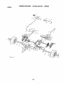
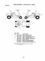
DRIVE
RIDING MOWER --CATALOG NO. WE261
32
RIDINGMOWER
--CATALOG
DRWE
KEY
PART
NO,
NO,
- 1
2
3
4
5
532
532
532
812
532
532
6
7
532 42 80-69
532 42 78-73
8
8!2
10
11
12
13
14
15
16
17
18
I9
20
21
532 42 88*76
532 00 13-70
532 43 06.45
532 43 08-45
532 42 79.46
532 12 47-93
532 42 79-26
5324281-06
532 42 47.59
532 43 09-70
532 42 79-97
532 42 80-77
22
23
24
25
532
532
532
532
KEY PART
NO. NO.
DESCRIPTION
43
43
12
O0
12
42
61-44
64-98
17-48
00-0I
35-83
79-39
10 00-09
42
43
42
42
80-76
13-74
79-95
83-03
26
27
532 42 98-16
532 42 90-53
28
29
30
31
32
33
34
35
36
37
38
532
532
532
532
532
582
532
532
872
873
532
42
17
18
42
42
42
42
19
11
80
16
83-02
48-40
39-00
90-55
84-64
84-61
84-62
64-92
04-06
04-00
54-92
NO.
SERVICE KIT, TRANSAXLE
WHEELASM (REAR)
WASHER, I6 GA.
E-CLIP
KEY, SQUARE
WELDMENT, DRIVE AXLE
CHAIN DRIVE
SPROCKET, 9 TOOTH
SPLINED
RING, SNAP
DIFFERENTIAL ASM
WASHER_ THRUST
CHAIN, PRIMARY DRIVE
BUSHING
BRACKE_, CARRIER
BEARING ASM
SHAFT INPUT
WHEEL, FRICTION A5M
ARM, SHIFT
ROD, BYPASS
BRACE CARRIER REAR
SPRING, CARRIER
SPRING, BRAKE
SPRING, BYPASS
BRACE CARRIER BOX
LINK, SHIFT
ARM, CLUTCH
WELDMENT SHIFT LEVER
SUPPORT, SHIFT LEVER
WASHER, NYLON
HUB SHIFT LEVER
SPACER, NYLON,
MNTG BRKT. SHIFT ARM
BRACKET_ SHIFTER FLEX
TUBE SHIFT ARM
GR(R HANDLE
BOLT, CARRIAGE - 114-20 X 3/4
NUT NYLON LOCK 114-20
BOLT, SHOULDER
33
39
40
41
42
43
45
46
47
48
49
50
51
52
53
54
55
56
57
58
59
60
61
62
63
64
65
66
67
68
69
70
71
72
73
874
8t0
819
532
873
817
819
817
532
532
532
532
532
877
532
532
532
532
532
817
532
532
532
877
876
532
532
532
817
532
817
532
812
532
78 04-t2
04 04-00
09 12-10
16 60-02
68 04-00
49 04-36
09 10-16
49 04-20
43 02.49
43 02-45
42 80-21
43 02-47
42 80-78
01 0B-10
42 80-19
42 80-17
43 52.53
42 80-16
12 47-88
49 05-08
42 84-60
42 79-45
42 96-78
10 08-12
02 02-08
42 93-25
42 96-94
42 96-93
49 04-06
42 80-70
00 05-12
43 64-99
00 00-02
42 95-19
WE261
DESCRIPTION
BOLT, 114-20 X 3/4
WASHER, LOCK
WASHER FLAT
WASHER, SERRATED
NUT, CROWN LOCK 114-20
SCREW 1/4-20 X2 114
WASHER
SCREW, 1/4-20 X 1 1/2
PLATE BRAKE ANTI - ROTATE
SPRING, BRAKE RETURN
ARM, BRAKE
SPACER RETURN
CALIPER, BRAKE ASM
PiN, DOWEL 1/4
PLATE, BRAKE PAD
PUCK BRAKE
ROTOR, BRAKE
CAR BRAKE CALIPER
PIN, RETAINER
BOLT, 5/t 6-16 X t12
CABLE, BRAKE
WELDMENT, PEDAL
ROD, PARKING BRAKE
PiN, .25 X .75 CLEVIS
PIN, 1/16 DIA. COTTER
BRACKET, BRAKE SUPPORT
COVER PEDAL
COVER, BRAKE PEDAL
SCREW, 114-20 X 3/8
BRAKE CABLE MOUNT
BOLT' 5/16-18 X 3/4
CAP HUB AXLE
E RING #5133-62
SPROCKET ]I TOOTH
SPLINED
NOTE: All component dimensions given in U.8. inches
1 inch = 25.4 mm
STEERING
RIDINGMOWER
- -CATALOG
LRV-S/ee_ing_l_r2
34
NO. WE261
RIDINGMOWER
--CATALOG
NO.
WE261
STEERING
KEY
NO,
PART
NO.
DESCRIPTION
1
2
8
4
8
6
7
8
9
t0
1
12
13
14
1s
18
17
18
19
20
21
22
23
24
25
28
27
28
29
30
532 43 65-00
812 00 00-01
882 t8 89-67
532 12 17-49
882 42 80-34
532 12 4-9-81
532 12 49,,37
532 42 10-78
819 13 14-14
532 42 80-57
532 42 80-35
532 42 80-36
874 78 05*24
819 13 10-16
878 80 o5-o0
582 42 80-44
532 42 82-52
532 I9 52-27
8170005-12
532 42 8045
532 42 83-47
582 42 82-13
532 18 67.37
8191838-12
873 94 08-00
532 48 65-01
532 4.3 65-02
832 19 98-49
532 42 80-38
532 43 64-99
WHEEL ASM (FRON_
E-CLIP
WASHER, HARDENED
WASHER, t/4 X 3/4
SPINDLE, RH
WASHER, HARDENED THRUST
BUSHING, STEERING COLUMN
PIN, 5,/84 X 3/4 CO_ER
WASHER
WELDMENT, LWR STRG SHAFT
LINK, STRNG LH
LINK, STRNG RH
BOLT, 5/16-18 X 1 1/2
WASHER
NUT, 5/16-t8
BUSHING, STEERING SNAP
SUPPORT, UPPER STEERING
BUSHING, UPPER STEERING
BOLT, 5,/t64 8 X 3/4
CLIP, RETAINER SPRING
COVER, STEERING COLUMN
SHAFt, STEERING
ADAPTER, STEERING WHEEL
WASHER_ 9/I 6 X 2 8/8 12 CA.
NUT, JAM LOCK 1/2-20
WHEEL, STEERING
CAR STEERING WHEEL
CUR RETAINER SPRING
SPINDLE, LH
CAR HUB, AXLE
NOTE: All component dimensions given in U,So inches
1 inch = 25,4 mm
35
MOWER
DECK
RIDINGMOWER--CATALOG
NO. WE261
LRV-Deck_'_j3
36
MOWER DECK
RIDING MOWER --CATALOG NO. WE261
KEY
PART
NO.
NO.
DESCRIPTION
1
2
532 42 81-93
632 1926-70
DECK, 26"
MANDREL
ASM
3
4
5
532 43 25-20
532 43 25-94
532 42 88-78
KEEPER,
PULLEY,
BELT
6
7
8
9
10
532
532
532
532
532
42
42
42
42
42
COVER,
MANDREL
LIFT ASM, DECK
LINK, DECK L]FF
LINK, ADJUSTABLE
DEFLECTOR
t 1
12
13
14
t5
I6
17
18
19
20
532
532
532
532
873
532
819
532
532
532
42 89-68
13 14-91
1970-26
4t 88-63
90 05-00
19 51-61
19 19-12
19 42-09
19 65-39
19 42-08
21
22
23
24
25
8191719-12
532 42 93-50
873 93 06-00
632 42 95..31
532 12 47-88
WASHER,
17/32
LINK, DECK
NUT, LCK 3/8-16
SPRING,
DECK
PIN
26
27
28
29
532
$32
532
532
I8
17
40
42
76-90
39-84
02-34
85-00
SPACER,
MANDREL
BOLT, MANDREL
NUT, LOCK
BLADE
30
3t
92
33
84
95
532
532
532
532
872
532
19
19
14
19
11
19
90-03
31-97
10-4-3
34-14
06-12
94-70
BOLT, BLADE
PULLEY, IDLER
GUARD,
IDLER
KEEPER,
BELT IDLER
BOLT, 3_-16
X 1 1,/2
ARM, BRAKE
36
37
38
532 18 77-29
873 90 06-00
532 42 84-35
SCREW,
1/4-20 X 5/8
NUT, 3/8-16 FLANGE
ARM, IDLER
39
40
41
817 49 05-08
819 17 16-16
532 10 53-04
BOLT, 8/16-t8
X 1/2
WASHER,
t6 GA.
CAR SLEEVE
42
43
44
45
662
582
532
532
NUT, PUSH
GRIR HANDLE
PLUNGER
PIN
11
12
42
10
82-42
93-95
91-95
93-97
81-46
04-52
88-31
94-01
57,.67
BELT
MANDREL
SUPPORT,
DEFLECTOR
ROD, HINGE
SPRING, TORSION
ARM, MOWER SUPPORT
NUT, LOCK
STUD
WASHER
PIN
BOLT, SHOULDER
PiN
X13!16
NOTE: All component dimensions given in U.S. inches
1 inch ,=25,4 mm
37
DECALS
RIDING
MOWER--CATALOG
NO.
WE261
6
/
4
KEY
PART
NO.
NO.
1
2
3
532 43 05-88
532 43 35-96
532 42 51-13
4
5
6
- - - - * _
532
532
532
532
532
532
532
532
DESCRIPTION
43
43
43
43
43
43
43
43
05-89
44-57
53-48
24-79
32-03
36-32
36-33
68-68
DECAL,
DECAL;
STEERING
WHEEL
V-BELT SCH 30"
DECAL,
DECAL,
DECAL,
WARN, DEFLECT/CTFGR
DECK/DEFLECTOR
WARNING
ENGINEGUARD
DECAL,
DECAL,
MANUAL
MANUAL
STRBRCKT
BYPASS
OPERATOR
OPERATOR
MANUAL
MANUAL
OPERATOR
OPERATOR
INSTALL
FRENCH
PORTUGUESE
NOTE: All component dimensions given inU.S. inches
1 inch = 25.4 mm
38
BOOT
ENGLISH
SPANISH
SUGGESTED
GUIDE
FOR SIGHTING
SLOPES
FOR SAFE OPERATION
ONLY RIDE UP AND DOWN HILL,
NOT ACROSS HILL
15 DEGREES
t
_
MAX.
down the face of slopes, never across the face. DO not mow
ARNING: To avoid serious injury, operate your tractor up and
slopes greater than 15 degrees. Make turns gradually to prevent
tipping or loss of control. Exercise extreme caution when
changing direction on slopes.
1. Fold this page along dotted line indicated above.
2. Hold page before you so that its left edge is vertically parallel to a tree
trunk or other upright structure,
3. Sight across the fold in the direction of hill slope you want to measure,
4. Compare the angle of the fold with the slope of the hilt.
03
IIIIIIIIIIIIIIIHI
III
IIIIIIIIIIIII
II
IIIIIII
IIIIIIIIIIIIIIIIII
WEEDEATER
°
PARTS AND SERVICE
This product has been expertly engineered and carefully manufactured to rigidquality standards. As with all
mechanical products, some adjustments or part repIacement may be necessary during the life of your unit.
For Parts and service, contact our authorized distributor: call 1-800-849-1297
For replacement parts, have available the following information:
a.
Model Number/Manufacturer's
b,
Description of part.
I.D. Number
For Technical Assistance: calt 1-800-829-5886
For a Parts Manual, go to our website: www.weedeater.com
HOP provides parts and service through its authorized distributors and dealers; therefore,
all requests for parts and servlce should be directed to your local dealer(s). The philosophy
of HOP is to continually improve all of its products. If the operating characteristics orthe
appearance of your product differs from those described in this Manual, please contact
your local dealer for updated information and assistance.
07.06.10 CL
m I
Printed in the U.S.A, _,j
I
II
I
IIIIIIIIII1[111111111
I II