1
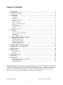
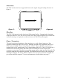
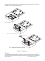
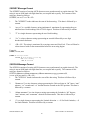
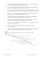
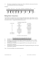
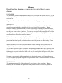
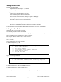
GPS GYRO COMPASS SYSTEM
OWNER'S MANUAL
PART NUMBER: GGC-E101
GPS Module and Dual Antenna System
WATSON INDUSTRIES, INC.
3035 MELBY STREET
EAU CLAIRE, WI 54703
Phone: (715) 839-0628
FAX: (715) 839-8248
email: [email protected]
Watson Industries, Inc.
GGC-E101 Rev A 08/30/2013
1
TABLE OF CONTENTS
1. Introduction ........................................................................................................ 3
2. Product Description............................................................................................ 3
3. Installation .......................................................................................................... 3
Environment .................................................................................................................................................3
Calibration ....................................................................................................................................................3
Orientation....................................................................................................................................................4
Figure 1 – Alignment....................................................................................................................................4
Mounting ......................................................................................................................................................4
Power / Connectors.......................................................................................................................................4
Figure 2 – GGC-E101 Stowed......................................................................................................................5
Deployment ..................................................................................................................................................5
Figure 3 – Deployment .................................................................................................................................6
Stowing.........................................................................................................................................................6
Figure 4 – Stowing .......................................................................................................................................7
4. Operation ............................................................................................................ 8
Power Up......................................................................................................................................................8
Figure 5 – GGC-E101 Deployed ..................................................................................................................8
Initialization..................................................................................................................................................8
Normal Operation.........................................................................................................................................9
5. Standard RS-232 Digital Output ........................................................................ 9
$GPHDT Message Format .........................................................................................................................10
$GPGGA Message Format.........................................................................................................................10
$GPGLL Message Format..........................................................................................................................12
$GPVTG Message Format .........................................................................................................................13
$GPRMC Message Format.........................................................................................................................14
6.
7.
8.
9.
Optional RS-232 Digital Output ...................................................................... 16
Mating Cable / Connections............................................................................. 17
Specifications ................................................................................................... 18
Dimensions....................................................................................................... 19
Figure 6 GGC-E101 ...................................................................................................................................19
Warning ......................................................................................................................................................20
10. Customer Service ............................................................................................. 21
11. Appendix A ...................................................................................................... 22
12. Appendix B....................................................................................................... 24
Determining and Setting Output Channels .................................................................................................24
Setting Output Format ................................................................................................................................25
Setting Heading Mode................................................................................................................................25
Watson Industries prides itself on solving customer problems and serving their needs in a timely fashion. This manual
is intended to facilitate this goal and to provide written information about your product. We ask that you carefully read
this manual. Becoming familiar with the manual will help you understand the product’s capabilities and limitations, as
well as provide you with a basic understanding of its operation. If, after reading the manual, you require further
assistance, do not hesitate to call Watson Industries with your questions and comments.
Watson Industries, Inc.
GGC-E101 Rev A 08/30/2013
2
CAUTION!
Watson Sensors are rugged devices that have been used successfully in a number of harsh
environments. The components have been qualified to withstand a mechanical shock of 200g 's or
greater, and most enclosures provide an added level of protection. However, dropping a sensor
from waist height onto a hard floor can cause a shock level of 600g's. At this level, damage is
likely to occur.
Introduction
The GPS Gyro Compass System (GGC-E101) is a solid-state sensor system that provides the user
with dynamic measurements of Angular Attitude and Heading, together with GPS output messages.
This System consists of a DMS unit and two mounted GPS antennas inside a water-resistant carry
case.
Product Description
Watson Industries GGC-E101 uses solid-state gyros and silicon accelerometers. The solid state
vibrating structure angular rate gyros used in this system provide extremely high reliability, high
precision, low power consumption and shock resistance. There are no physical adjustments
required by the user since all of the primary transducers are locked into position during
manufacture.
The GGC-E101 incorporates a dual antenna Differential GPS (DGPS) system that allows the GGC
to output true North heading. This unit outputs Altitude, Latitude and Longitude based on the
position of the aft antenna.
This unit will operate in two heading modes. The unit operates in true North heading mode (“G”
label header on output message) when in dual antenna GPS is valid. In the event of loss of the GPS
signal, the unit switches to relative heading (“I” label header on output message) based on the last
accurate GPS heading. When GPS signal is restored, the unit reverts to true North heading when
dual antenna GPS is restored. The user may select to hold the unit in relative heading mode full
time. (See Appendix A Setting Velocity and Heading Modes)
Installation
Environment
Avoid mounting sites that are subject to significant temperature changes over the duration of the
test. Temperature variation could induce noticeable rate sensor bias drift, which could result in
degraded attitude accuracy.
This sensor system is housed in a water-resistant case. This case is air transportable and buoyant.
The GGC is a rugged device and will withstand harsh environments. However, due attention needs
to be paid to the nature of the sensor and its prime function, which is to measure attitude and
motion.
Calibration
The GGC is calibrated at the factory before it is shipped to the user. It is recommended that the
unit be returned to the factory annually for evaluation and recalibration.
Watson Industries, Inc.
GGC-E101 Rev A 08/30/2013
3
Orientation
The GGC unit side that has carrying handle needs to be aligned along the heading direction. See
Figure 1.
Heading Direction
Figure 1 –
Alignment
Handle
Mounting
The GGC-E101 case needs to be placed on a flat horizontal surface. Unsnapping the four plastic
clasps opens the GGC case. The case cover needs to be fully opened so that the cover is below the
antennas when they are deployed to avoid interference with the GPS satellite signals.
Power / Connectors
This unit has an internal regulator to allow operation over a wide voltage input range. Best
operation is obtained at either 24 or 28 VDC, although operation is fully satisfactory down to 15
VDC and up to 35 VDC. Power draw of the unit is about 7 Watts. The GGC power system is
isolated from the GGC signal system. The 65-meter mating cable (GGC Cable –65) for this unit is
included and coiled inside the lid. This cable needs to be attached to a power supply and a
computer to receive data. The cable is removed by opening the five straps that secure the cable. The
necessary length of cable can then be uncoiled. The Red and Black wires need to be connected to
the DC power Supply. The Orange, White and Brown wires need to be connected to the RS-232
port of data collection computer. For more information on the cable hookup see page 17.
Watson Industries, Inc.
GGC-E101 Rev A 08/30/2013
4
Wire straps
Metal clasp
Antenna arm
Antenna assembly
straps
Figure 2 – GGC-E101 Stowed
Deployment
After the unit is aligned and connections have been completed, the antennas can be deployed. See
Figure 3 for information on deploying the antennas. First open the two straps that secure the
antenna assembly. Now pivot the assembly up and toward the side of the case. Be careful not to
pinch your fingers between the antenna assembly and case side. Next swing the left-hand antenna
arm counterclockwise until it is fully extended. Please note that the antenna arms are secured with
Velcro patches. Use the left-hand metal clasp to secure this antenna arm in its extended position.
Now swing the right-hand antenna arm counterclockwise until it is fully extended. Use the righthand metal clasp to secure this antenna arm in its extended position. The GGC needs an
Watson Industries, Inc.
GGC-E101 Rev A 08/30/2013
5
unobstructed view of the entire sky to receive signals from GPS satellites. The GGC is now ready
to operate. See the Operation Section on page 8.
Step 1 – Open Case
Step 2 – Raise Antenna Assembly
Step 3 – Extend antenna arms and secure metal clasps
Figure 3 – Deployment
Stowing
When finished taking measurements with the GGC it is time to repack the unit. First shutoff the
DC power supply to the unit and remove Red and black wires from power supply. Next disconnect
Watson Industries, Inc.
GGC-E101 Rev A 08/30/2013
6
the RS-232 serial connection to the computer. See Figure 4 for information for help in stowing the
antenna assembly and cable. Now unclasp the right-hand antenna and swing the antenna arm
clockwise to the stowed position. Next unclasp the left-hand antenna and swing the antenna arm
clockwise to the stowed position. Make sure the two straps that secure the antenna assembly are
open and out of the way. Pivot the antenna assembly down and into the bottom of the case. Be
careful not to pinch your fingers between the antenna assembly and case bottom. Now the antenna
assembly can be secured by closing the straps. Next the Power/signal cable needs to be stowed.
Make sure the five straps that secure the cable are open and out of the way. Rewind the cable onto
its holder inside the cover. Secure the cable by closing the five straps. Close the cover and secure
by snapping the four plastic clasps.
Step 1 – Release metal clasps
and stow antenna arms.
Step 2 – Lower Antenna Assembly
Step 3 – Close Case
Figure 4 – Stowing
Watson Industries, Inc.
GGC-E101 Rev A 08/30/2013
7
Operation
Power Up
The GGC unit output messages can be read by using a terminal program. Now it is time to power
up the data collection computer and start the terminal program for the serial port connected to the
GGC. Next the power needs to be switched on for the GGC unit.
Figure 5 – GGC-E101 Deployed
Initialization
Ideally, the GGC should be stationary and level when it is turned on. If not, the sensor readings
may not be immediately accurate after initialization. The time required for the initialization
process takes 4 to 5 seconds. During this time, a message is sent from the unit via the RS-232
serial link. This message gives information about the GGC such as the full model number, serial
number, and software revision.
Watson Industries, Inc.
GGC-E101 Rev A 08/30/2013
8
Example of the GGS header:
GGC-E101 INITIALIZING
SERIAL NUMBER - 0177
LAST CALIBRATED - 10/12/10
SOFTWARE VERSION - GG01_00A 2010-12-13
COPYRIGHT (C) 1990 THROUGH 2010
WATSON INDUSTRIES, INC.
Normal Operation
During normal operation, the GGC will output highly accurate inertial data for the user to interpret.
This data is transmitted using the RS-232 serial output. The unit also relays GPS messages. The
exact formatting structure is discussed later in the Interface section of this manual.
In normal operation, the GGC takes data from its rate sensors and integrates in a closed loop
system, with the accelerometers as a long-term reference, to generate Bank, Elevation and Heading
data. In most cases, these algorithms provide for very stable and accurate output signals; however,
the user should be aware that exceeding the normal ranges of the sensors would affect accuracy.
The GGC gyros have a maximum rate of 100°/s. Care should be taken not to exceed this rate
because the closed loop system will receive inaccurate data. This will result in errors in the angle
output signals. The GPS Velocity data is used to assist in the correction of errors. The internal GPS
receiving unit provides this signal.
The Heading Angle is referenced to the fore-aft alignment of the two GPS antennas using the true
North GPS Heading (the string start label is “G”). If GPS becomes unavailable, relative heading
will be maintained (the string start label is “I”).
While this GGC is "all attitude", the accuracy deteriorates rapidly when its forward direction is
within about 5 degrees of vertical. Operation for any extended period of time in this orientation is
not recommended. If these few operational precautions are observed, the GGC should provide very
accurate data for a wide variety of applications.
Standard RS-232 Digital Output
The standard RS-232 output consists of a five NMEA GPS messages. These strings of decimal
ASCII characters sent asynchronously at regular intervals. Nominally, the string is sent at 9600
baud with eight data bits, one stop bit and no parity. The mating cable for the GGC is included. The
RS-232 signal is referenced to signal ground. The frame rate is 1 frame of five GPS messages per
second. The five GPS messages are GPHDT, GPGGA, GPGLL, GPVTG, GPRMC. The unit is
shipped configured for this output.
Here is an example of the five string frame:
$GPHDT,175.58,T*0C
$GPGGA,175612.00,4451.84239,N,09128.00147,W,2,06,1.1,275.2,M,-33.0,M,6.0,0133*7B
$GPGLL,4451.84239,N,09128.00147,W,175612.00,A,D*78
$GPVTG,186.55,T,187.35,M,0.13,N,0.24,K,D*25
$GPRMC,175612.00,A,4451.84239,N,09128.00147,W,0.13,186.55,081210,0.8,W,D*39
Watson Industries, Inc.
GGC-E101 Rev A 08/30/2013
9
$GPHDT Message Format
The $GPHDT consists of a string ASCII characters sent asynchronously at regular intervals. The
string is sent at 9600 baud with eight data bits, one stop bit and no parity. The contents of this
string are formed as follows:
$GPHDT,xxx.xx,T*cc<CR><LF>
1.
The ”$GPHDT” header indicates the start of the data string. . This data is followed by a
comma.
2.
“xxx.xx” is a variable character string (minimum-4, maximum-6) representing the gyro
stabilized true North heading 0.00 to 359.99 degrees. This data is followed by a comma.
3.
“T” is a single character representing the true North heading.
4.
“*cc” is a three character string representing an asterisk followed by a two digit
hexadecimal checksum.
5.
<CR><LF> The string is terminated by a carriage return and Line Feed. There will then be
a short interval with no data transmission before the next string begins.
Example:
$GPHDT,175.58,T*0C
$GPHDT message Header
175.58 True Heading 175.58 deg
T True Heading
*0C Checksum
$GPGGA Message Format
The $GPGGA consists of a string ASCII characters sent asynchronously at regular intervals. The
string is sent at 9600 baud with eight data bits, one stop bit and no parity. The contents of this
string are formed as follows:
$GPGGA,hhmmss.ss,ddmm.mmmmm,s,dddmm.mmmmm,s,n,qq,p.p,saaaaa.a,M,
±xxxx.xx,M,sss,aaaa*cc<CR><LF>
1.
The ”$GPGGA” header indicates the start of the data string. This data is followed by a
comma.
2.
“hhmmss.ss” is a nine character string representing the Universal time in “hh” hours, “mm”
minutes, “ ss” seconds and “.ss” decimal fraction seconds at the GPS position. This data is
followed by a comma.
3.
“ddmm.mmmmm” is a nine character string representing the Latitude in “dd” degrees,
“mm” minutes, and “.mmmmm” decimal fraction minutes. This data is followed by a
comma.
4.
“s” is a single character representing the Latitude direction. s = N for North Latitude, s = S
for South Latitude. This data is followed by a comma.
Watson Industries, Inc.
GGC-E101 Rev A 08/30/2013
10
5.
“dddmm.mmmmm” is an eleven character string representing the Longitude in “ddd”
degrees, “mm” minutes, and “.mmmmm” decimal fraction minutes. This data is followed
by a comma.
6.
“s” is a single character representing the Longitude direction. s = E for East Longitude, s =
W for West Longitude. This data is followed by a comma.
7.
“n” is a single character representing the Quality indicator. n = 0 for no position, n = 1 for
undifferentially correction position, n = 2 for differentially correction position, 9 = position
computed using almanac. This data is followed by a comma.
8.
“qq” is two characters representing the number of satellites used in position computation.
This data is followed by a comma.
9.
“p.p” is a three character string representing the Horizontal Dilution of Precision (HDOP) =
1.0 to 9.9. This data is followed by a comma.
10.
“saaaaa.a” is a variable character string (minimum-3, maximum-8) representing the
Antenna Altitude in meters above sea level. This data is followed by a comma.
11.
“M” is the altitude units, meters. This data is followed by a comma.
12.
“±xxxx.x” is a variable character string (minimum-4, maximum-7) representing the geoidal
separation in meters. It difference between the WGS-84 earth ellipsoid and mean-sea-level
(geoid). This data is followed by a comma.
13.
“M” is the geoidal separation units, meters. This data is followed by a comma
14.
“sss” is a variable character string (minimum-0, maximum-3) representing the age of
Differential Corrections in seconds. Field blank if not Differentially corrected. . This data is
followed by a comma
15.
“aaaa” is a four character string representing Reference station identification (0000 – 1023).
Field blank if not Differentially corrected.
16.
“*cc” is a three character string representing an asterisk followed by a two digit
hexadecimal checksum.
17.
<CR><LF> The string is terminated by a carriage return and Line Feed. There will then be
a short interval with no data transmission before the next string begins.
Example:
$GPGGA,175612.00,4451.84239,N,09128.00147,W,2,06,1.1,275.2,M,-33.0,M,6.0,0133*7B
$GPGGA message Header
175612.00 Universal Time 17 Hrs 56 minutes 12.00 seconds
4451.84239 Latitude 44 deg 51.84239 minutes
N North Latitude
09128.00147 Longitude 91 deg 28.00147 minutes
W West Longitude
2 Quality factor = 2 Diff. Corrected Pos.
Watson Industries, Inc.
GGC-E101 Rev A 08/30/2013
11
06 6 satellites being used
1.1 HDOP = 1.1
275.2,M Altitude = 275.2 Meters
geoidal separation –33.0 meters -33.0,M
Differential Correction Age= 6.0 seconds 6.0
Reference Station Identification 0133
Checksum *7B
$GPGLL Message Format
The $GPGLL consists of a string ASCII characters sent asynchronously at regular intervals. The
string is sent at 9600 baud with eight data bits, one stop bit and no parity. The contents of this
string are formed as follows:
$GPGLL,ddmm.mmmmm,s,dddmm.mmmmm,s,hhmmss.ss,a,i*cc<CR><LF>
1.
The ”$GPGLL” header indicates the start of the data string. This data is followed by a
comma.
2.
“ddmm.mmmmm” is a nine character string representing the Latitude in “dd” degrees,
“mm” minutes, and “.mmmmm” decimal fraction minutes. This data is followed by a
comma.
3.
“s” is a single character representing the Latitude direction. s = N for North Latitude, s = S
for South Latitude. This data is followed by a comma.
4.
“dddmm.mmmmm” is an eleven character string representing the Longitude in “ddd”
degrees, “mm” minutes, and “.mmmmm” decimal fraction minutes. This data is followed
by a comma.
5.
“s” is a single character representing the Longitude direction. s = E for East Longitude, s =
W for West Longitude. This data is followed by a comma.
6.
“hhmmss.ss” is a nine character string representing the Universal time in “hh” hours, “mm”
minutes, “ ss” seconds and “.ss” decimal fraction seconds at the GPS position. This data is
followed by a comma.
7.
“a” is a single character representing the Status. a = A for data valid,
a = V for data invalid. This data is followed by a comma
8.
“i” is a single character representing the Mode Indicator. i = A for Autonomous, i = D for
Differential, i = E for Estimated.
9.
“*cc” is a three character string representing an asterisk followed by a two digit
hexadecimal checksum.
10.
<CR><LF> The string is terminated by a carriage return and Line Feed. There will then be
a short interval with no data transmission before the next string begins.
Watson Industries, Inc.
GGC-E101 Rev A 08/30/2013
12
Example:
$GPGLL,4451.84239,N,09128.00147,W,175612.00,A,D*78
$GPGLL message Header
4451.84239 Latitude 44 deg 51.84239 minutes
N North Latitude
09128.00147 Longitude 91 deg 28.00147 minutes
W West Longitude
175612.00 Universal Time 17 Hrs 56 min 12.00 sec
A Status = valid data
D Mode Indicator = Differential
*78 Checksum
$GPVTG Message Format
The $GPVTG consists of a string ASCII characters sent asynchronously at regular intervals. The
string is sent at 9600 baud with eight data bits, one stop bit and no parity. The contents of this
string are formed as follows:
$GPVTG,ttt.tt,c,ttt.tt,c,ggg.gg,u,ggg.gg,u,i*cc<CR><LF>
1.
The ”$GPVTG” header indicates the start of the data string. . This data is followed by a
comma.
2.
“ttt.tt” is a variable character string (minimum-4, maximum-6) representing the True course
over ground. 0.00 to 359.99 degrees. This data is followed by a comma.
3.
“c” is a single character representing true course over ground indicator.
c = T (always) for True Heading. This data is followed by a comma.
4.
“ttt.tt” is a variable character string (minimum-4, maximum-6) representing the Magnetic
course over ground. 0.00 to 359.99 degrees. This data is followed by a comma.
5.
“c” is a single character representing magnetic course over ground indicator.
c = M (always) for Magnetic Heading. This data is followed by a comma.
6.
“ggg.gg” is a variable character string (minimum-4, maximum-6) representing the speed
over ground. 0.00 to 999.99 knots. This data is followed by a comma.
7.
“u” is a single character representing speed over ground units.
u = N (always) for Nautical mile/hour. This data is followed by a comma.
8.
“ggg.gg” is a variable character string (minimum-4, maximum-6) representing the speed
over ground. 0.00 to 999.99 km/hour. This data is followed by a comma.
9.
“u” is a single character representing speed over ground units.
u = K(always) for kilometer/hour. This data is followed by a comma.
10.
“i” is a single character representing the Mode Indicator. i = A for Autonomous, i = D for
Differential, i = E for Estimated.
Watson Industries, Inc.
GGC-E101 Rev A 08/30/2013
13
11.
“*cc” is a three character string representing an asterisk followed by a two digit
hexadecimal checksum.
12.
<CR><LF> The string is terminated by a carriage return and Line Feed. There will then be
a short interval with no data transmission before the next string begins.
Example:
$GPVTG,186.55,T,187.35,M,0.13,N,0.24,K,D*25
$GPVTG message Header
186.55 True Course over ground 261.74 degrees
T True Heading
187.35 Magnetic Course over ground 262.26 degrees
M Magnetic Heading
0.13 Speed over ground 0.13 knots
N Knots
0.24 Speed over ground 0.24 Km/hr
K Km/hr
D Mode Indicator = Differential
*25 Checksum
$GPRMC Message Format
The $GPRMC consists of a string ASCII characters sent asynchronously at regular intervals. The
string is sent at 9600 baud with eight data bits, one stop bit and no parity. The contents of this
string are formed as follows:
$GPRMC,hhmmss.ss,ddmm.mmmmm,s,dddmm.mmmmm,s,zzz.zz,ttt.tt,ddmmyy,ddd.d,v,
i*cc<CR> <LF>
1.
The ”$GPRMC” header indicates the start of the data string. This data is followed by a
comma.
2.
“hhmmss.ss” is a nine character string representing the Universal time in “hh” hours, “mm”
minutes, “ ss” seconds and “.ss” decimal fraction seconds at the GPS position. This data is
followed by a comma.
3.
“a” is a single character representing the Status. a = A for data valid,
a = V for data invalid. This data is followed by a comma
4
“ddmm.mmmmm” is a nine character string representing the Latitude in “dd” degrees,
“mm”minutes, and “.mmmmm” decimal fraction minutes. This data is followed by a
comma.
5.
“s” is a single character representing the Latitude direction. s = N for North Latitude, s = S
for South Latitude. This data is followed by a comma.
6.
“dddmm.mmmmm” is an eleven character string representing the Longitude in “ddd”
degrees, “mm” minutes, and “.mmmmm” decimal fraction minutes. This data is followed
by a comma.
Watson Industries, Inc.
GGC-E101 Rev A 08/30/2013
14
7.
“s” is a single character representing the Longitude direction. s = E for East Longitude, s =
W for West Longitude. This data is followed by a comma.
8.
“zzz.zz” is a variable character string (minimum-4, maximum-6) representing the ground
speed. 0.00 to 999.99 knots. This data is followed by a comma.
9.
“ttt.tt” is a variable character string (minimum-4, maximum-6) representing the Track made
good, referenced to true North.. 0.00 to 359.99 degrees. This data is followed by a comma.
10.
“ddmmyy” is a six character string representing the UTC date of position fix. “dd” day,
”mm” month, “yy” year . This data is followed by a comma.
11.
“ddd.d” is a variable character string (minimum-3, maximum-5) representing Magnetic
Variation 0.0 to 180.0 degrees. This data is followed by a comma.
12.
“v” is a single character representing the Magnetic Variation direction. s = E for East
Longitude, s = W for West Longitude. This data is followed by a comma.
13.
“i” is a single character representing the Mode Indicator. i = A for Autonomous, i = D for
Differential, i = E for Estimated.
14.
“*cc” is a three character string representing an asterisk followed by a two digit
hexadecimal checksum.
15.
<CR><LF> The string is terminated by a carriage return and Line Feed. There will then be
a short interval with no data transmission before the next string begins.
Example:
$GPRMC,175612.00,A,4451.84239,N,09128.00147,W,0.13,186.55,081210,0.8,W,D*39
$GPRMC message Header
175612.00 Universal Time 21 Hrs 46 minutes 57.00 seconds
A Status = valid data
4451.84239 latitude 44 deg 51.84043 minutes
N North Lattitude
09128.00147 Longitude 91 deg 28.00263 minutes
W West Longitude
0.13 Speed over ground 0.13 knots
Track Made Good 186.55 degrees 186.55
UTC Date of postion fix 08 December 2010 081210
Magnetic Variation 0.8 degrees 0.8
West Magnetic Variation W
Mode indicator = Differential D
*39 Checksum
Watson Industries, Inc.
GGC-E101 Rev A 08/30/2013
15
Optional RS-232 Digital Output
The optional RS-232 output consists of a string of decimal ASCII characters sent asynchronously at
regular intervals. Nominally, the string is sent at 9600 baud with eight data bits, one stop bit and
no parity. The mating cable for the GGC is included. The RS-232 signal is referenced to signal
ground. The frame rate is 10 strings per second. See Appendices A and B for information on how
to change the unit for this output. The contents of a string are formed as follows:
1.
A single letter and a space used to indicate the start of the data string. The letter “G”
indicates the start of an inertial data string with successful GPS data input. The letter “I”
indicates the start of an inertial data string with GPS disabled or absence of valid GPS data.
The letter “R” indicates the start of a Reference data string. If the letter is in lower case
(“g”,“i”, or “r”), an error over-range condition is indicated
This occurs when the calculated attitude or heading errors exceed preset ranges. Internal
functions that require these error values are disabled while the condition exists. The system
will continue to operate in an extended time constant mode with a low level of error
accumulation until the condition is cleared. While maneuvering, occasional blips of this
condition are expected with no detectable effect on the resulting data.
2.
A nine character string representing the Universal Time (UTC) starting with six digits, a
decimal point, one digit and a space for up to 235959.9 Hours minutes seconds tenth
seconds (HHMMSS.S). Note: The field is filled with asterisks when the data is invalid.
(“******.*”)
3.
A seven character string representing the bank angle starting with a “+” or a “-“, followed
by three digits, a decimal point, one digit and a space for up to ±179.9 degrees.
4.
A six character string representing the elevation angle starting with a “+” or a “-“, followed
by two digits, a decimal point, one digit and a space for up to ±89.9 degrees.
5.
A six character string representing the heading angle by three digits, a decimal point, one
digit and a space for zero to 359.9 degrees.
6.
A seven character string representing the GPS Ground Track/Forward Velocity starting
with a “+” or a “-“, followed by three digits, a decimal point, one digit and a space for up to
±399.9 Km/Hr. Note: The field is filled with asterisks when the data is invalid. (“****.*”)
7.
A twelve character string representing the Latitude starting four digits, a decimal point, five
digits, a comma, followed by an “N” or “S” and a space for up to ±89degrees 59.99999
minutes North or South. Note: The field is filled with asterisks when the data is invalid.
(“****.****,*”)
8.
A thirteen character string representing the longitude starting with a five digits, a decimal
point, five digits, a comma, followed by a ”W” or “E” and a space for up to 179 degrees
59.99999 minutes East or West. The field is filled with asterisks when the data is invalid.
(“*****.*****,*”)
9.
A six character string representing the Altitude by five digits and a space for up to 21500
feet. The field is filled with asterisks when the data is invalid. (“*****”).
Watson Industries, Inc.
GGC-E101 Rev A 08/30/2013
16
10.
The string is terminated by a carriage return. There will then be a short interval with no
data transmission before the next string begins.
Example:
G 161409.9
↑
(1)
-000.8
↑
UTC
(2)
space
+00.1
↑
Bank
angle
(3)
space
273.4
+028.9
↑
Elev.
angle
(4)
space
↑
Head.
angle
(5)
space
4451.84413,N
↑
Velocity
(6)
space
space
09128.00182,W
↑
Latitude
(7)
00894
<CR>
↑
Longitude
(8)
space
↑
Altitude
(9)
space
(10)
space
Mating Cable / Connections
The GGS-E101 is supplied with a 65 meter mating Cable (Part Number: GGC Cable –65). This
cable terminated at one end with mating 10 pin MIL-C-26482 connector (MS3116F12-10S) and
four inch wire lead (1” stripped and tinned) at the other end.
7 conductor mating Cable
Connector Pin
A
B
C
D
E
F
G
H
J
K
No Connection
No Connection
Wire Color
Black
Red
No Connection
Orange
White
Brown
No Connection
No Connection
No Connection
No Connection
Green
Blue
Description
Power Ground
V+ Power In
Not Used
RS-232 RXD
RS-232 TXD**
Signal Ground
Not Used
Not Used
Not Used
Not Used
Not Used
Not Used
**User Receives data from this line
1)
2)
3)
4)
5)
Wiring direction for the mating cable GGC Cable –65)
The Black wire is attached to the power supply Ground.
The Red wire is attached to Power Supply V+ (unit will work from +18 to +35 VDC).
The Orange wire is attached to the computers RS-232 transmit line (pin 3 on the 9-pin
D-sub RS-232 connector).
The White wire is attached to the computers RS-232 receive line (pin 2 on the 9-pin
D-sub RS-232 connector).
The Brown wire is attached to the computers RS-232 signal ground line (pin 5 on the 9-pin
D-sub RS-232 connector).
Note: The Green and Blue wires remain unconnected.
Watson Industries, Inc.
GGC-E101 Rev A 08/30/2013
17
Specifications
Attitude
Range: Bank
Range: Elevation
Resolution:
Accuracy: Static
* Accuracy: Dynamic
Heading
Range:
Resolution:
Accuracy: Static
* Accuracy: Dynamic
Angular Rate
Range: Roll, Pitch, Yaw
Resolution:
Scale Factor Accuracy:
Bias: Roll, Pitch, Yaw
Non-Linearity:
Bandwidth:
Noise:
Acceleration
Range: X, Y, Z
Range: Forward, Lateral, Vertical
Resolution:
Scale Factor Accuracy:
Bias: X, Y, Z
Non-Linearity:
Bandwidth:
GPS Positioning
Range: Latitude
Range: Longitude
Range: Altitude
Resolution: Latitude, Longitude
Resolution: Altitude
Accuracy: Latitude, Longitude
Environmental
Temperature: Operating
Temperature: Storage
Vibration: Operating
Vibration: Survival
Shock: Survival
Electrical
Frame Rate:
Startup Time: Data
†
Startup Time: Satellite Acquisition
‡
Input Power:
Input Current:
Digital Output:
Physical
Axis Alignment:
Size: Antenna Stowed
Weight:
Connection:
*
†
‡
•
•
±180°
±75°
0.02°
±0.25°
±0.5%
Binary mode (14 bit)
0° - 360°
0.02°
±0.3° RMS
±0.5%
Binary mode (14 bit)
Using GPS
±0.05°/sec (without GPS)
±100°/sec
0.025°/sec
±0.5%
< 0.1°/sec
< 0.1%
20 Hz
< 0.02°/sec rms
Binary mode (14 bit)
Digital ASCII
Full scale range
±10g
±10g
4mg
1%
< 10mg
0.1%
3 Hz
Full scale range
±90°
±180°
0ft to 21500ft
0.00001 minutes
2 ft
±0.6m (with DGPS)
±2.5m (without DGPS)
-30°C to +70°C
-55°C to +85°C
5g rms
10g rms
500g
20 Hz to 2 KHz
20 Hz to 2 KHz
10ms ½ sine wave
71.1 Hz
5 sec
5 min
18 to 35VDC
240mA @ 28VDC
RS-232
Maximum
Typical
7.0W
280mA @ 24VDC
< 0.1°
24.3"W x 19.5"L x 8.7"H
37 lb
MS3112E12-10P
61.7 x 49.5 x 22.1 (cm)
17 kg
Mating: MS3116F12-10S
Using velocity data with GPS mode on.
Actual accuracy can be calculated as the listed percentage multiplied by the change in value over the entire dynamic maneuver.
Acquisition time for GPS units is typical for the contiguous United States. Acquisition time may differ due to interference in your
geographic area.
Including losses using 65 meter cabling.
Specifications are subject to change without notice.
This product may be subject to export restrictions. Please consult the factory.
Watson Industries, Inc.
GGC-E101 Rev A 08/30/2013
18
Z
Dimensions
Z
Handle
X
Z
Y
Figure 6 GGC-E101
Dimensions in inches
Watson Industries, Inc.
GGC-E101 Rev A 08/30/2013
19
X
FORWARD
Y
Y
X
Warning
Rough handling, dropping, or miswiring this unit is likely to cause
damage.
DISCLAIMER
The information contained in this manual is believed to be accurate and reliable; however, it is the
user’s responsibility to test and to determine whether a Watson Industries’ product is suitable for a
particular use.
Suggestion of uses should not be taken as inducements to infringe upon any patents.
WARRANTY
Watson Industries, Inc. warrants, to the original purchaser, this product to be free from defective
material or workmanship for a period of two full years from the date of purchase. Watson
Industries’ liability under this warranty is limited to repairing or replacing, at Watson Industries’
sole discretion, the defective product when returned to the factory, shipping charges prepaid, within
two full years from the date of purchase. The warranty described in this paragraph shall be in lieu
of any other warranty, express or implied, including but not limited to any implied warranty of
merchantability or fitness for a particular purpose.
Excluded from any warranty given by Watson Industries are products that have been subject to
abuse, misuse, damage or accident; that have been connected, installed or adjusted contrary to the
instructions furnished by seller; or that have been repaired by persons not authorized by Watson
Industries.
Watson Industries reserves the right to discontinue models, to change specifications, price or
design of this product at any time without notice and without incurring any obligation whatsoever.
The purchaser agrees to assume all liabilities for any damages and/or bodily injury that may result
from the use, or misuse, of this product by the purchaser, his employees or agents. The purchaser
further agrees that seller shall not be liable in any way for consequential damages resulting from
the use of this product.
No agent or representative of Watson Industries is authorized to assume, and Watson Industries
will not be bound by any other obligation or representation made in connection with the sale and/or
purchase of this product.
PRODUCT LIFE
The maximum expected life of this product is 20 years from the date of purchase. Watson
Industries, Inc. recommends the replacement of any product that has exceeded the product life
expectation.
Watson Industries, Inc.
GGC-E101 Rev A 08/30/2013
20
Customer Service
All repairs, calibrations and upgrades are performed at the factory. Before returning any product,
please contact Watson Industries to obtain a Returned Material Authorization number (RMA).
Return Address & Contact Information
Watson Industries, Inc.
3035 Melby Street
Eau Claire, WI 54703
ATTN: Service Department
Telephone: (715) 839-0628
Fax: (715) 839-8248
email: [email protected]
Returning the Product
Product shall be packaged making sure there is adequate packing around all sides. Please write the words,
FRAGILE, DELICATE INSTRUMENT in several places on the outside of the shipping container.
Correspondence shall include:
•
•
•
•
•
Customer’s Name and Address
Contact Information
Equipment Model Number
Equipment Serial Number
Description of Fault
It is the customer’s responsibility to pay all shipping charges from customer to Watson
Industries, including import and transportation charges.
Watson Industries, Inc.
GGC-E101 Rev A 08/30/2013
21
Appendix A
The following data items are available in the Optional RS-232 Digital Output. Their full-scale ranges are listed. See
Appendix B for more information.
Inertial Output
Full Scale Decimal
Time
UTC 1
HHMMSS
±179.9º
±89.9º
0.0 to 359.9º
±9.99 G
±9.99 G
±9.99 G
±9.99 G
±9.99 G
±9.99 G
±99.9 º/s
±99.9 º/s
±99.9 º/s
±99.9 º/s
±399.9 Km/hr
±89.99999
±179.99999
21500 Feet
-40º to 88ºC
Bank Angle
Elevation Angle
Heading Angle
X Accelerometer
Y Accelerometer
Z Accelerometer
Forward Acceleration
Lateral Acceleration
Vertical Acceleration
X Angular Rate
Y Angular Rate
Z Angular Rate
Heading Rate
Ground Track 2 / Forward Velocity
Latitude 3
Longitude 3
Altitude 4
Temperature
Status Bits
Flag Bits
3 ASCII chars representing
Octal digits
3 ASCII chars representing
Octal digits
1
Note: The GPS universal time (UTC) field is filled with asterisks when the data is invalid.
(“******”)
2
Note: The Ground Track Velocity field is filled with asterisks when the data is invalid.
(****.*)
3
Note: The Latitude and Longitude fields are filled with asterisks when the data is invalid.
(“****.*****,* *****.*****,*”)
4
Note: The Altitude field is filled with asterisks when the data is invalid.
(*****)
Watson Industries, Inc.
GGC-E101 Rev A 08/30/2013
22
The Status Bits contain the following information:
Bit
Description (If Set)
0
Bank Error Flag
1
Elevation Error Flag
2
Heading Error Flag
3
System Error Flag
4
Velocity Error Flag
5
Ready Flag
6
Checksum Error Flag
e.g.
Status
bit 6
bit 5
bit 4
bit 3
bit 2
bit 1
bit 0
= 040(octal) =
0 100 000 (binary)
is reset - No Checksum Error
is set
- Ready
is reset – No Velocity Error
is reset – No System Error
is reset – No Heading Error
is reset – No Elevation Error
is reset – No Bank Error
The Flag Bits contains the following information:
Bit
Description (If Set)
0
GPS ground track heading data loss
1
GPS ground track velocity data loss
2
GPS true heading data loss
3
Reference Command selected
4
GPS enabled
5
Free Mode selected
6
Logic Input Switches disabled
e.g.
Flags = 120(octal) =
1 010 000 (binary)
bit 6 is set
- Logic Input disabled
bit 5 is reset - not in Free Mode
bit 4 is set
- GPS enabled
bit 3 is reset – not in Reference Mode
bit 2 is reset - valid GPS true heading data
bit 1 is reset - valid GPS ground track velocity data
bit 0 is reset - valid GPS ground track heading data
Watson Industries, Inc.
GGC-E101 Rev A 08/30/2013
23
Appendix B
Determining and Setting Output Channels
For Optional RS-232 Digital Output
To determine which channels are present.
Hook the unit up to your computer’s serial port.
Use a terminal program to interface with the unit.
Turn on unit. Wait for the startup message to appear on display.
Hit the space bar twice within the first 5 seconds of turn on.
Sometimes it takes a few tries to get the hang of this.
Wait 15 seconds.
Now the unit will take in keyboard commands.
To determine which channels are present, first type '&'.
This will bring up the menu:
TYPE IN
1 =
2 =
3 =
4 =
5 =
THE NUMBER OF YOUR SELECTION (OR 'Q' TO QUIT):
ADJUST TIME CONSTANTS
SET OUTPUT CHANNELS
LIST CURRENT OUTPUT CHANNEL SELECTION
SELECT HEADING SOURCE
SET NEW BAUD RATE
Typing '3' will show which channels are currently active.
To change which channels are output, type '&' (this will bring up the menu again).
Now type '2' to set up the channels.
The following message will appear:
TO SET FOR OUTPUT FOR ANY OF THE FOLLOWING DATA ITEMS, PRESS Y
TO AVOID ANY OF THE FOLLOWING DATA ITEMS, PRESS N
TO QUIT AND DISREGARD ANY OTHER DATA, PRESS Q
*** DO YOU WANT TO PROCEED? (Y/N/Q)
To proceed type 'Y' or 'y'
Now each channel will come up one at a time.
For example:
DO YOU WANT OUTPUT OF TIME?
Type 'Y' or 'y' to output the channel, type 'N' or 'n' to remove the channel.
When you get to bottom of list, this message will appear:
Y = GOBACK, N = INSTALL DATA & QUIT, Q = QUIT
DO YOU WANT TO TRY TO SET DATA AGAIN?
To accept the channels as selected, type 'N' or 'n', then press the space bar to resume data output.
To make this channel selection the default the next time you power the unit on type " (a quote mark).
Watson Industries, Inc.
GGC-E101 Rev A 08/30/2013
24
Setting Output Format
There are two output formats:
Optional Decimal ASCII output – '_' Command.
Standard output – '%' Command.
To change the output format:
Connect the unit to your computer’s serial port.
Use a terminal program to interface with the unit.
Turn on the unit. Wait for the startup message to appear on the display.
Press the space bar twice within the first 5 seconds of turn on.
Sometimes it takes a few tries to get the hang of this.
Wait 15 seconds.
Now the unit will take in keyboard commands.
Press the key Command corresponding to the format you want to switch into.
To make this output selection the default the next time you power the unit on type " (a quote mark.)
Setting Heading Mode
Connect the unit to your computer’s serial port.
Use a terminal program to interface with the unit.
Make sure the GPS Disable Command Line is tied to signal ground so that unit can receive computer commands.
Turn on unit. Wait for the startup message to appear on display.
Press the space bar twice within the first 5 seconds of turn on.
Sometimes it takes a few tries to get the hang of this.
Wait 15 seconds.
Now the unit will take in keyboard commands.
To set the heading mode, type '&'.
This will bring up the menu:
TYPE IN
1 =
2 =
3 =
4 =
5 =
THE NUMBER OF YOUR SELECTION (OR 'Q' TO QUIT):
ADJUST TIME CONSTANTS
SET OUTPUT CHANNELS
LIST CURRENT OUTPUT CHANNEL SELECTION
SELECT HEADING SOURCE
SET NEW BAUD RATE
Typing '4' will bring up this menu:
SELECTION HEADING SOURCE (OR 'Q' TO QUIT):
1 = GPS TRUE NORTH HEADING (GPHDT GPS Message Required)
2 = RELATIVE HEADING
To set the heading mode to GPS True North Heading type '1'.
To set the heading mode to Relative Heading type '2'
To make any of these modes the default the next time you power the unit on type " (a quote mark.)
Watson Industries, Inc.
GGC-E101 Rev A 08/30/2013
25