1
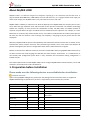
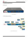
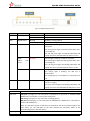
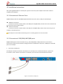
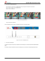
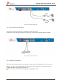
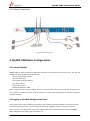
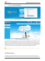
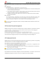
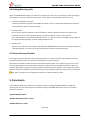
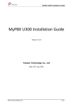
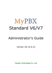
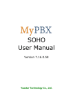
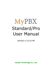
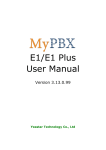
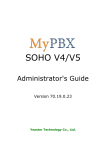
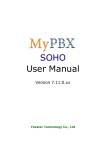
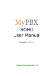
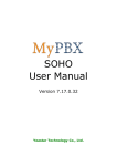
MyPBX U200 Installation Guide MyPBX U200 Installation Guide Version: V1.0 Yeastar Technology Co., Ltd Date: 14th, January, 2013 http://www.yeastar.com 1/13 MyPBX U200 Installation Guide Contents 1. PREPARATION BEFORE INSTALLATION ....................................................................................... 3 2. HARDWARE SPECIFICATIONS ...................................................................................................... 4 2.1 Overview ............................................................................................................................ 4 2.2 LED Indicators and Ports .................................................................................................... 4 2.3 Specifications and Operating Environment ....................................................................... 6 3. MYPBX U200 INSTALLATION ....................................................................................................... 6 3.1 Placement Instructions ....................................................................................................... 6 3.2 Installation Instructions ..................................................................................................... 7 3.2.1 Connection of Ethernet Ports .......................................................................................... 7 3.2.2 Connection of FXO/GSM/UMTS/BRI ports ...................................................................... 7 3.2.3 Connection of FXS ports .................................................................................................. 9 3.2.4 Power Connection ........................................................................................................... 9 3.2.5 Overall Flow Chart......................................................................................................... 10 4. MYPBX U200 BASIC CONFIGURATIONS .................................................................................... 10 4.1 Factory Defaults ............................................................................................................... 10 4.2 Logging in the Web Configuration Panel ......................................................................... 10 4.3 Network Settings .............................................................................................................. 11 4.4 Extensions Setup and management ................................................................................. 12 4.5 Configuring Terminals ...................................................................................................... 12 4.6 Making/Receiving calls .................................................................................................... 13 4.7 Reset to Factory Defaults ................................................................................................. 13 5. CONCLUSION ............................................................................................................................. 13 http://www.yeastar.com 2/13 MyPBX U200 Installation Guide About MyPBX U200 MyPBX U200 is a workhorse designed for companies requiring up to 50 concurrent calls and 200 users. It supports PSTN, ISDN BRI lines, GSM/UMTS networks and VoIP. Also, it is equipped with an audio input port and an audio output port. MyPBX U200 is truly unrivalled for features and value. MyPBX U200’s scalability is impressive too. With the deployment of MyPBX U200, the company will no more worry about the high expansion costs and the waste of their previous investment. The modular technology enables the company to freely choose the combination of FXO, FXS, BRI, GSM, and UMTS modules as required, and just add on the type of modules that are needed for future expansion. For example, if 2 more PSTN lines are required, they needn’t bother to buy a new PBX. Just add another O2 module (2 FXO ports) is OK. Also, the new user account is free of charge. The company is not going to pay any license fees for new employees. Moreover, MyPBX U200 has perfect interoperability with mainstream IP Phone brands such as Yealink, Snom, Grandstream, Aastra, Polycom and Cisco. Auto provisioning of Yealink, Snom, Cisco, Aastra and Polycom IP phones would greatly save time on configurations when there is bulk extensions to register. Besides, customers from different countries will all feel comfortable while using MyPBX U200. Because they are able to select their local language for Web GUI and Voice Prompt. Furthermore, it is renowned for its user-friendly web configuration panel which is easy accessible and self-evident making configuration a trouble-free job. This Guide explains how to install MyPBX U200, how to configure MyPBX U200 via web interface, how to add extensions, and make/receive calls via PSTN lines. 1. Preparation before Installation Please make sure the following devices are available before installation: Contents of the box Upon receiving MyPBX U200 gift box, please open the package and check if all the items are supplied as MyPBX U200 Packing List (See Sheet 1). If there is any problem, please contact your provider. Item Unit QTY Description MyPBX U200 PC 1 MyPBX U200 main box Power cord PC 1 For the input of 220V AC power Warranty card PC 1 With Series Number printed for Repair & Return CD PC 1 including all the MyPBX User Manuals and relative documents phone line PC 2 Network Cable PC 1 Serial Line PC 1 Mounting ear PC 2 Screws PC 8 8 screws (φ3.0*6mm) for mounting ears Sheet 1 MyPBX U200 Packing List http://www.yeastar.com 3/13 MyPBX U200 Installation Guide 2. Hardware Specifications 2.1 Overview Figure 2-1 MyPBX U200 2.2 LED Indicators and Ports Figure 2-2 MyPBX U200 Front Panel http://www.yeastar.com 4/13 MyPBX U200 Installation Guide Figure 2-3 MyPBX U200 Rear Panel LED Power Indication Power status Status On Off RUN MyPBX status Blinking Not Blinking/Off 1-16 FXO port status Red light GSM/ UMTS status Red light port BRI port status Orange light FXS port status Green light Ports RJ11 ports Antenna ports Description The power is switched on The power is switched off MyPBX is running properly MyPBX goes wrong The red light is blinking: the PSTN line hasn’t been connected the red and green lights are blinking alternately: there is incoming call The red and green light are blinking alternately and rapidly: the call is connected and the trunk is in use. The red light is blinking: no SIM card inserted The red and green lights are blinking alternately: there is incoming call The red and green lights are blinking alternately and rapidly: the call is connected and the trunk is in use. Orange light: indicates the BRI port The orange light is blinking: the BRI line is disconnected The orange light is on: the BRI line is connected or in use The green and red lights are blinking alternately: the FXS port is ringing The green and red lights are blinking alternately and rapidly: the call is connected and the FXS port is in use Description FXO port (red light): For the connection of PSTN lines or FXS ports of traditional PBX. MyPBX users could make or receive calls via FXO port. FXS port (green light): For the connection of analog phones. BRI port (orange light): For the connection of ISDN BRI lines. MyPBX users could make or receive calls via BRI port. Note: The sequence number of the ports corresponds to that of the Indicator lights in the front panel. (I.e. the LED lights in the front indicate the connection status of the corresponding ports at the back panel.) For the connection of GSM/UMTS Antenna. http://www.yeastar.com 5/13 MyPBX U200 Installation Guide Console port For debugging USB port For the storage of call recording files Ethernet ports MyPBX U200 provides two 10/100M adaptive RJ45 Ethernet ports, marked as LAN and WAN. -LAN port: LAN port is for the connection to Local Area Network (LAN). -WAN port: WAN port is the network port for the connection to internet. It supports ‘DHCP server’, ‘PPPoE/dynamic DNS’, and “static IP” for IP address assignment. Reset Button Press the reset button to restore the factory defaults Please make sure that you’d like to reset because once reset, the previous configurations would be erased automatically. Power port For the connection of a power adapter to input 100~240V、50~60HZ AC power 2.3 Specifications and Operating Environment Description Size L 340 * W 210 * H 44 (mm) Power Supply Operating Temperature 220V,50~60HZ 0°C~50°C (32°F~122°F) Storage Temperature -10°C~65°C (14°F~149°F) Operating Humidity 5%~90% (Non-condensing) Storage Humidity 0%~95% (Non-condensing) Weight 2.1kg 3. MyPBX U200 Installation To avoid unexpected accident, personal injury or device damage, please read the following instructions before installing MyPBX U200. 3.1 Placement Instructions Ambient Temperature: to avoid overheating, please do not run MyPBX U200 in the place where the ambient temperature is above 122℉ (50℃). Ventilation: please make sure that the device has good ventilation around. Anti-jamming—there may be some sources of interference that might affect the normal running of MyPBX U200. It’s highly recommended that the device Should be placed away from high-power radio, radar transmitters and high frequency, and high-current devices. Is using independent power junction box and effective anti-grid interference measures have been taken. Mechanical load--Please make sure that the device is placed steadily to avoid any accident that might cause damage. If placed on the desktop, please ensure it is horizontally placed. http://www.yeastar.com 6/13 MyPBX U200 Installation Guide 3.2 Installation Instructions After placing MyPBX U200 in a suitable place, please connect the power adapter and all other cables to complete the installation. 3.2.1 Connection of Ethernet Ports MyPBX U200 provides two 10/100M adaptive RJ45 Ethernet ports, that is, LAN port and WAN port. WAN Port Connection Connect one end of a network cable to the WAN port of MyPBX U200, and the other end to the Ethernet port of a hub, switch or ADSL modem. LAN Port Connection Connect one end of a network cable to the LAN port of MyPBX U200, and the other end to any port of company’s LAN switch/router. If the LAN port is connected to PC directly (not via a switch), please use cross-over cable. 3.2.2 Connection of FXO/GSM/UMTS/BRI ports MyPBX U200 supports various outside lines (e.g. FXO, GSM/UMTS, or BRI). Below are the connection instructions of each kind of outside line taking the device installed with 2 FXO ports, 2 GSM ports, and 2 BRI ports as an example. 1. Connection of FXO ports The FXO port could be connected to the PSTN line or the FXS port of a traditional PBX with a phone line. For instance, if No.2 and No.4 connectors are FXO ports, the connection could be depicted as below: Figure 3-1 Connection of FXO ports http://www.yeastar.com 7/13 MyPBX U200 Installation Guide 2. Connection of GSM/UMTS ports If No.3 and No.7 connectors are GSM/UMTS Ports, the steps of connection are as below: Step 1: Open the Upper case of MyPBX U200 Step 2: Insert the SIM card: Figure 3-2 Inserting the SIM Card Step 3: Connect the antenna Once completed, the No.3 and No.7 LED lights would turn red as below figure: Figure 3-3 Connection of GSM/UMTS ports 3. Connection of BRI ports The BRI port could be connected to the BRI line and the BRI port of a traditional PBX with a BRI RJ45-RJ11 cable. For instance, if No.14 and No.16 connectors are BRI ports, the connection could be depicted as below: http://www.yeastar.com 8/13 MyPBX U200 Installation Guide Figure 3-4 Connection of BRI ports 3.2.3 Connection of FXS ports The FXS port could be connected to an analog phone with a phone line. For instance, if No.6 and No.8 connectors are FXS ports, the connection could be depicted as below: Figure 3-5 Connection of FXS ports 3.2.4 Power Connection Once users have made sure that device installation, cable connection and power type is correct, please switch on the power. Then MyPBX U200 will start booting. In the meantime, users would see that the ‘POWER’ and ‘RUN’ indicator lights would turn on. Please switch off the power before plugging or unplugging the cables. http://www.yeastar.com 9/13 MyPBX U200 Installation Guide 3.2.5 Overall Flow Chart Figure 3-6 Overall Flow Chart 4. MyPBX U200 Basic Configurations 4.1 Factory Defaults MyPBX U200 provides web-based configuration interface for administrator and account user. The user can manage the device by log in the web interface. The factory default IP address: LAN: 192.168.5.150; Access path: http://[IP address] User Name: admin; Password: password Default SIP UDP port: 5060 There are 6 extensions set up by default. The user could use these extensions directly, edit or delete them. Their extension numbers are “300”-“305” (6 numbers in a row) whose passwords are “pincode + respective extension number”. 4.2 Logging in the Web Configuration Panel Firstly, please check if the IP address that assigns to the network port (LAN or WAN) is in the same segment with the PC and which can be connected when commit ‘Ping +MyPBX IP address’ command. Start the browser on PC. In the address bar, enter the IP address, click ‘enter’ button and then you can see MyPBX Web Configuration Panel login page (See Figure 4-1). http://www.yeastar.com 10/13 MyPBX U200 Installation Guide Figure 4-1 MyPBX Web Configuration Panel Login Page Enter the Admin User Name and Password to log in. Figure 4-2 MyPBX Admin Configuration Interface Via the configuration interface, the admin can make all the system configurations, including network settings (LAN, WAN, Firewall, VPN, DDNS, VLAN, etc.); system parameters configuration (system prompts, time zone, password, etc.); internal settings (Web access port, user extension range, business hours, conference room, paging and intercom, music on Hold, etc.); inbound routes; outbound routes; user account management (add or delete an extension account, IP restriction, features setup, etc.); extended function management (call queue, conference room, IVR, etc.); call logs (search, download); firmware update and reset, etc. Please note that after saving the changes, please remember to click the “Apply changes” button to make the changes take effect. 4.3 Network Settings After logging in the admin configuration interface, generally the first step is to configure the IP address. If both the WAN and LAN ports are connected to the network, their IP addresses need to be configured. If not, http://www.yeastar.com 11/13 MyPBX U200 Installation Guide just configuring the IP address of the LAN port which is connected to the local area network of the company is OK. WAN Settings Click “Network Settings”->”WAN Settings” on the left menu bar. 1. If the network that the WAN port is connected to is using DHCP server as connection method, please select the “DHCP” (dynamic IP) option. 2. If the network connection method is “Static IP address”, please select this option and enter the LAN parameters (IP address, subnet mask, default gateway, DNS, etc.) 3. If MyPBX is connected to ADSL adapter directly, please select “PPPoE” option and enter the ADSL user name and password. LAN Settings Click “Network Settings”->”LAN Settings” on the left menu bar of the web configuration interface. LAN port is used for the interoperability of IP terminals and MyPBX. If the LAN port is connected to the company’s LAN, please configure the correct IP address and corresponding subnet mask. Please note that after changing the IP address of LAN port, MyPBX should be rebooted to make the new changes take effect. 4.4 Extensions Setup and management MyPBX has already set up 6 extensions by defaults which are extension”300-305”. The password is “pincode + extension number”. It’s up to the user to use these default extensions directly or after changing the password. Of course, they could be deleted. The admin could add, edit or delete the extensions via the Web Configuration Panel. In the “Extensions” page, there are “Add Extension”, “Add Bulk Extensions”, “Delete the Selected Extension” and “Edit Extension”(configure the features such as call forwarding and voicemail) subpages, etc. 4.5 Configuring Terminals MyPBX could be connected with SIP-based audio and video IP terminal devices (e.g. IP Phone, voice gateway, and soft terminal, etc.). The steps of configuring terminals are as below: Step 1: Make sure the IP terminal and MyPBX are interconnected Step 2: Enter the IP address of MyPBX when configuring “SIP server”, “Proxy server”, or “Registration server” of the IP terminals, and the default SIP UDP port is 5060. Step 3: Enter the account registration information with the “extension number/password” of the default or newly setup extensions of MyPBX. For more information on terminal configuration, please refer to http://www.yeastar.com/Solutions/SIP_Phones.asp Step 4: Reboot the IP terminal after configuration, and click “Status Monitor”->”Line Status” on the menu bar of MyPBX web configuration interface to check if it has registered successfully to MyPBX. http://www.yeastar.com 12/13 MyPBX U200 Installation Guide 4.6 Making/Receiving calls Note: The MyPBX default settings are sufficient to make phone calls. It is not necessary to make any changes unless the user wants to create new extensions or trunks. Refer to Administrator’s Guide for more. 1. Internal calls between extensions If two IP terminals have registered to MyPBX successfully, the user could make calls between extensions just by dialing the other’s extension number. 2. Outbound calls Firstly, please connect a PSTN line to the first FXO port. Then the default extensions are able to make outbound calls via this trunk by simply dialing “9+phone number+#”. The “#” is Key as Send. Note: The dial pattern of the default outbound route is “9.”. But if the user has changed it, please dial the new prefix instead of the digit “9” when making outbound calls. 3. Inbound calls When the user calls the trunk number of the PSTN line, MyPBX would route the call to IVR (the “welcome” prompt) by default. Then the user can dial the extension number following the prompt. 4.7 Reset to Factory Defaults If you forget the new IP address or the password of admin, or in other cases that you would like to restore the factory defaults, please reset the device following the below instructions: Please press the “RESET” button located in the back panel with a paper clip or a pencil tip, then you can see all of the LED indicators in the front panel would all turn red first and turn orange seconds later. When the indicator light becomes orange, the button could be released and system begins to reset. During the process, please do not power off until the LED indicators become normal which means the reset process is completed. Note: After resetting, all the configurations made by the admin would be erased. 5. Conclusion This Installation Guide only explains the installation and basic settings of MyPBX U200 for making and receiving calls. For more functionality and advanced settings of MyPBX U200, please refer to the relative documents as below: “MyPBX U200 Datasheet” “MyPBX U200 Administrator’s Guide” “MyPBX U200 User’s Guide” [The End] http://www.yeastar.com 13/13