1
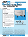
POWERMITE® GAS BOOSTER HEATER
INSTALLATION, OPERATING, SERVICE AND PARTS MANUAL
MODEL: PMG-100 & PMG-200
I&W #07.05.055.00
WATER HEATERS FOR OTHER THAN RECREATIONAL VEHICLE INSTALLATION
ONLY
CHAUFFE-EAU POUR INSTALLATION AUTRE QUE DANS DES VÉHICULES DE
LOISIR UNIQUEMENT
WARNING: If the information in these
instructions is not followed exactly, a fire or
explosion may result causing property
damage, personal injury or death.
- Do not store or use gasoline or other
flammable vapors and liquids in the
vicinity of this or any other appliance.
- WHAT TO DO IF YOU SMELL GAS:
• Do not try to light any appliance.
• Do not touch any electrical switch;
do not use any phone in your building.
• Immediately call your gas supplier
from a neighbor’s phone. Follow the
gas supplier’s instructions.
• If you cannot reach your gas supplier,
call the fire department.
- Installation and service must be
performed by a qualified installer,
service agency or the gas supplier.
AVERTISSEMENT: Assurez-vous de
bien suivre les instructions données dans
cette notice pour réduire au minimum le
risque d’incendie ou d’explosion ou pour
éviter tout dommage matériel, toute
blessure ou la mort.
- Ne pas entreposer ni utiliser d’essence
ou ni d’autres vapeurs ou liquides
inflammables à proximité de cet
appareil ou de tout autre appareil.
- QUE FAIRE SI VOUS SENTEZ UNE
ODEUR DE GAZ:
• Ne pas tenter d’allumer d’appareil.
• Ne touchez à aucun interrupteur; ne
pas vous servir des téléphones se
trouvant dans le bâtiment.
• Appelez immédiatement votre
fournisseur de gaz depuis un voisin.
Suivez les instructions du fournisseur.
• Si vous ne pouvez rejoindre le
fournisseur, appelez le service des
incendies.
- L’installation et l’entretien doivent être
assurés par un installateur ou un
service d’entretien qualifié ou par le
fournisseur de gaz.
CONTENTS
Plumbing........................................................11
Gas................................................................15
Electrical........................................................18
Venting ..........................................................19
Operation ............................................................22
Start-Up Procedures......................................22
Maintenance .......................................................24
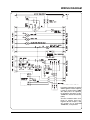
Wiring Diagram...................................................29
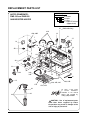
Replacement Parts List .....................................30
Hatco Limited Warranty.....................................32
Authorized Parts Distributors ............Back Cover
Important Safety Instructions ............Front Cover
Important Owner Information...............................i
Introduction ...........................................................i
Model Description ................................................1
All Models........................................................1
System Overview .................................................1
Specifications .......................................................2
Dimensions......................................................3
Booster Heater Sizing Chart ...........................4
Installation ............................................................7
General............................................................7
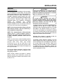
IMPORTANT OWNER INFORMATION
Record the model number, serial number
(identification plate located on the lower right hand
side, front corner of the unit), voltage and purchase
date of your Powermite® Gas Booster Heater in the
spaces below. Please have this information
available when calling Hatco for service assistance.
Business
Hours:
8:00 a.m. to 5:00 p.m.
Central Standard Time
Model No. ________________________________
Telephone: (800) 558-0607; (414) 671-6350
Serial No. ________________________________
Fax:
(Summer Hours: June to September –
8:00 a.m. to 5:00 p.m. C.D.T.
Monday through Thursday
8:00 a.m. to 2:30 p.m. C.D.T. Friday)
Voltage __________________________________
(800) 690-2966 (Parts & Service)
(414) 671-3976 (International)
24-Hour 7-Day Parts & Service
Assistance available in the
United States and Canada
by calling (800) 558-0607.
Date of Purchase __________________________
Additional information can be found by visiting our
web site at www.hatcocorp.com.
INTRODUCTION
This manual provides the installation, safety and
operating instructions for the Powermite Gas
Booster Heater. We recommend all installation,
operating and safety instructions appearing in this
manual be read prior to installation or operation of
your Hatco PMG-100 or PMG-200 Gas Booster
Heater. Safety instructions that appear in this
and the words
manual after a warning symbol
WARNING or CAUTION printed in bold face are very
WARNING means there is the
important.
possibility of serious injury or death to yourself or
CAUTION means there is the possibility
others.
of minor or moderate injury. CAUTION without the
symbol signifies the possibility of equipment or
property damage only.
Hatco Powermite Gas Booster Heaters are
instantaneous fin tube type heaters designed to
boost the temperature of regularly available hot
water, usually 110°F to 150°F (43°C to 66°C) up to
180°F (82°C). Water at 180°F (82°C) can be used
as sanitizing rinse water in commercial dishwashers
in accordance with Health Codes and National
Sanitation Foundation Standard #5.
The Hatco Gas Booster Heater is design certified
by CSA International and tested under the
requirements of the American National Standard,
ANS Z21.10.3*CSA 4.3-2001, Current Edition.
All Hatco Gas Booster Heaters are factory
pre-plumbed and pre-wired to allow for easy
installation. The control compartment area is
accessible from the front, which permits easy
installation, even when near other equipment.
Hatco Gas Booster Heaters are a product of
extensive research and field testing. The materials
used were selected for maximum durability,
attractive appearance and optimum performance.
Every unit is thoroughly inspected and tested prior to
shipment.
Hatco Gas Booster Heaters are quality built for long
life and rugged dependability. Dependability of the
booster heater is preserved through proper, safe
installation and operation.
Form No. PMG-100/200M-0805
i
MODEL DESCRIPTION
ALL MODELS
Water enters the booster heater at the inlet water
connection and flows into the stainless steel tank. It
then is pumped through the finned tube heat
exchanger where it is heated to the proper
temperature. The heated water then returns back to
the top half of the stainless steel tank for supply to
the dishwashing machine. Water that is not
immediately used by the dishwashing machine is
recirculated through the heat exchanger by the
water pump.
This system is designed to assure the availability of
the proper temperature water at the heater outlet.
All Hatco booster heaters are warranted to be free
of defects in material and workmanship under
normal use and service, and when installed in
accordance with factory recommendations.
NOTE: Hatco Booster Water Heaters are approved
for use with commercial dishwashers only.
SYSTEM OVERVIEW
The Hatco Powermite Gas Booster Heater is
designed to maintain a temperature of 180°F
(82°C) water required for the rinse cycle of a
commercial dishwasher. An inlet water temperature
of at least 110°F (43°C) will produce optimum
results (See Capacity Chart and Booster Heater
Sizing Chart in SPECIFICATIONS).
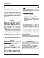
If the unit overheats above the setpoint temperature,
the safety high limit will open, shutting down the
burner, locking out the controller, and turning on the
alarm pilot light. In order to reset the unit, turn the
unit off and depress the reset button on the
appropriate high limit switch, the tank high limit is
located behind front panel on the left hand side of
the vertical control panel. The heat exchanger high
limit is located on the front of the heat exchanger.
The switches will not reset until the temperature has
dropped to a safe level. This unit must remain off for
at least 10 seconds before it can be restarted.
After the necessary power, water and gas
connections are completed, start the unit by turning
on the toggle switch located on the lower front base.
The water circulating pump will start at this time.
Providing the operating and safety controls are
satisfied, the ignition module will begin a 20 second
safety pre purge, next it will energize the spark
igniter and turn on the gas for the pilot. The igniter
will spark for about 90 seconds or until proof of fire.
If there is a confirmed pilot fire, and the water
temperature is below the setpoint, the unit will go
into full burn. The unit will stay in full burn until the
desired setpoint temperature is met, then the burner
will shut off. During standby periods of limited use,
the burner will cycle on only to replace standby
water temperature loss. If for some reason the unit
did not ignite there is an automatic 5 minute delay
before the unit attempts to ignite again.
NOTE: The operating thermostat control is factory
preset at 190°F (88°C).
NOTE: The circulator pump will stay on as long as
the toggle switch is in the ON position.
1
Form No. PMG-100/200M-0805
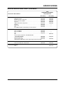
SPECIFICATIONS
Type:
Gas-fired, instantaneous recirculating booster heater with accumulator for use with
door type dishwashers. Unit is floor mounted.
Capacity:
PMG-100:
PMG-200:
Fuel:
Natural gas @ 5 iwc or Propane @ 11 iwc – minimum inlet gas pressure.
Operating
Water Pressure:
150 PSI max. Relief valve set at 150 PSI, 210°F (99°C).
Power:
Supply 120 VAC, 15 amp service (unit uses 3.0 amps @ 120 volts).
Ignition:
Electronic spark pilot with flame proofing by rectification.
Input 105,000 BTUs/Hour. Output 84,800 BTUs/Hour = 24.8 kW
Input 195,000 BTUs/Hour. Output 156,000 BTUs/Hour = 45.7 kW
Temperature Control: Electronic, temperature control probe/microprocessor based. Factory preset at
190°F (88°C).
Safety Systems:
Energy cut off devices include manual reset heat exchanger high limit and manually
reset tank high limit. Redundant gas solenoid valve with integral regulator.
Temperature/Pressure relief valve on tank.
Fluing:
Direct – combustion air enters bottom, flue gases exit right side or back at top of
unit.
Vent:
Forced draft system with 4" (102 mm) diameter vent pipe adapter.
Pump:
Recirculating with bronze housing.
Connections:
Gas – 3/4" NPT, Water – 3/4" NPT, Electric – 120 VAC, 15 Amp.
Ship Weight:
PMG-100:
PMG-200
155 pounds (70 kg) dry.
195 pounds (89 kg) dry.
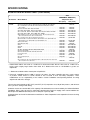
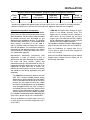
WATER TEMPERATURE RECOVERY TABLE - FAHRENHEIT
INPUT MBH
Gallons per Hour (GPH) at Indicated Temperature Rise (F°)
MODEL
(1,000 BTU/HR)
30°
40°
50°
60°
70°
PMG-100
105
321
241
193
161
138
PMG-200
195
602
452
361
301
258
NOTE: Capacity is reduced @ altitudes above 2000 feet (610 m). See HIGH ALTITUDE INSTALLATION &
OPERATION section for sizing considerations.
Form No. PMG-100/200M-0805
2
SPECIFICATIONS
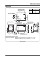
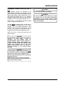
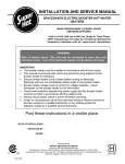
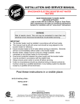
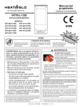
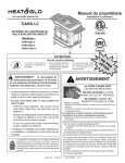
DIMENSIONS
Straight out duct adaptor
shown. Replace with 90°
adaptor for other duct
configurations.
A
120-150°F (49-66°C)
Water Inlet
180°F (82°C) Water Outlet
Model
A DIM.
B DIM.
PMG-100
27-7/16
2-15/16
PMG-200
35-15/16
5-11/16
6-1/16
11-1/8
20-3/4
14-1/2
5-3/4
2-1/4
Primary exhaust
exit location at rear
Gas Inlet
6-1/4
13
T/P relief valve may
be field installed at
side or rear
B
Unit may be adapted in
field with supplied parts
for side exhaust exit.
31-1/4
19-5/8
25-3/4
1-13/16
11-1/16
25-7/8
19-5/8
25-13/16
7-3/16
6-1/16
17
6-1/4
Ø7/8 hole for
1/2" conduit
6-5/16
Power switch
Power on lamp
Reset safety switch lamp
NOTE: Dimensions listed are in inches.
NOTE: Overall Dimensions
PMG 100: 27-1/2" W x 20-3/4" D x 31" H (699 x 527 x 787 mm)
PMG 200: 36" W x 20-3/4" D x 31" H (914 x 527 x 787 x mm)
Figure 1. Top View
3
Form No. PMG-100/200M-0805
SPECIFICATIONS
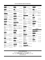
BOOSTER HEATER SIZING CHART
GAS
POWERMITE® BOOSTER†
Temperature Rise
Dishwasher Model Number
40°F (22°C)
70°F (39°C)
ADAMATION
CSL-1390, CA-2, CA-3, CA-4, SLAP 44, CA, CA-1 . . . . . . . . . . . . .PMG-200 . . . . . . .(2)PMG-200
BLAKESLEE
Series “R & “F”-CC, -EE, -LL, -MM, -LLL, -MMM, -PCC,
-PEE, -PLL, -PMM (multi-tank) with suffix “LC” . . . . . . . . . . . . . . .PMG-200
Series XF-LL, XF-PLL, XF-MM, XF-PMM, XF-EEE,
XF-LLL, XF-MMM, (Multi-tank) with suffix “LC” . . . . . . . . . . . . . . .PMG-200
DD-8 . . . . . . . . . . . . . . . . . . . . . . . . . . . . . . . . . . . . . . . . . . . . . . . . .PMG-100
Series R-L, R-PL, R-M, R-PM, F-L, F-PL, F-M, F-PM (single tank) .PMG-200
Series XF-PEE, XF-PLL, XF-PMM, XF-EEE, XF-LLL, XF-MMM
(multi-tank) . . . . . . . . . . . . . . . . . . . . . . . . . . . . . . . . . . . . . . . . . . .PMG-200
FA (Flight-A-Round) and RA (Rack-A-Round) use comparable “F” listing.
CHAMPION
. . . . . . .PMG-200/100
. . . . . . . . . . .--. . . . . . . .PMG-200
. . . . . . .(2)PMG-200
. . . . . . .(2)PMG-200
D-H1C, D-H1TC . . . . . . . . . . . . . . . . . . . . . . . . . . . . . . . . . . . . . . . . . . .--- . . . . . . . . . . .PMG-100
66 WSPW, 44-WS, 66-WS . . . . . . . . . . . . . . . . . . . . . . . . . . . . . . . . . . .--- . . . . . . . . . . .PMG-100
UC-CW6-WS, US-CW8-WS . . . . . . . . . . . . . . . . . . . . . . . . . . . . . . .PMG-100 . . . . . . . .PMG-200
44, 66 PW, 70FFPW, 80HDPW, 54, 76PW, 80FFPW,90HDPW 64,
90FFPW, 100HDPW, 86 PW . . . . . . . . . . . . . . . . . . . . . . . . . . . . .PMG-100 . . . . . . . .PMG-200
40-KB, 40-KB-2-2, 40-KFWB, 40-KPRB, 40-KPRB-2-2,
40KPRB-2-3, 60-KB, 60-KB-2-2, 60-KFWB, 60-KFWB-2-2,
60-KPRB, 60-KPRB-2-3, 64KB, 64-KB Corner, 64-KPRB,
64-KPRB Corner, 64 Modular, 86 Modular . . . . . . . . . . . . . . . . . . .PMG-200 . . . . . . .PMG-200/100
44-KB, 44-KB Corner, 44-KPRB, 44-KPRB Corner, 54-KB,
54-KB Corner, 54-KPRB, 54-KPRB Corner, 44 Modular,
66 PW Modular, UC** Series 6’ Center, UC-C4 . . . . . . . . . . . . . . .PMG-200 . . . . . . .PMG-200/100
UC-CW4, UC-C . . . . . . . . . . . . . . . . . . . . . . . . . . . . . . . . . . . . . . . . .PMG-200 . . . . . . .PMG-200/100
UC**CW Series 6’ Center . . . . . . . . . . . . . . . . . . . . . . . . . . . . . . . . .PMG-200 . . . . . . .(2)PMG-200
W-6-WS . . . . . . . . . . . . . . . . . . . . . . . . . . . . . . . . . . . . . . . . . . . . . . .PMG-200 . . . . . . .(2)PMG-200
CMA
DISHMACHINES
CMA-44H with tank heater, CMA-66H . . . . . . . . . . . . . . . . . . . . . . . .PMG-100 . . . . . . . .PMG-200
HOBART
AM-12, AM-12C*, AM-14, AM-14C . . . . . . . . . . . . . . . . . . . . . . . . . . . . .--- . . . . . . . . . . .PMG-100
Opti-RinSe C44A, CRS-66A, CCS-66A, CPW-80A, C54A,
CRS-76A, CCS-76A, CPW-90A, C64A, CRS-86A, CCS-86A,
CPW-100A, C-88A, CRS-110A, CCS-110A, CPW-124A . . . . . . . .PMG-100 . . . . . . . .PMG-200
C-54A, CRS-76A, CPW-90A, CCS-76A . . . . . . . . . . . . . . . . . . . . . .PMG-200 . . . . . . .PMG-200/100
C-44A, CRS-66A, CCS-66A, CPW-80A, C-64A, CRS-86A,
CCS-86A, CPW-100A . . . . . . . . . . . . . . . . . . . . . . . . . . . . . . . . . . .PMG-200 . . . . . . .PMG-200/100
C-88A, CRS-110A, CPW-124A, CCS-110A . . . . . . . . . . . . . . . . . . .PMG-200 . . . . . . .PMG-200/100
Opti-RinSe C44AW, CRS-66AW, CCS-66AW, CPW-80AW . . . . . . . . . .--- . . . . . . . . . . .PMG-100
C-44AW, CRS-66AW, CPW-80AW, CCS-66AW . . . . . . . . . . . . . . . .PMG-100 . . . . . . . .PMG-100
C-44, CRS-66, CPW-80 . . . . . . . . . . . . . . . . . . . . . . . . . . . . . . . . . .PMG-200 . . . . . . .PMG-200/100
C-54, CRS-76, CPW-90 . . . . . . . . . . . . . . . . . . . . . . . . . . . . . . . . .PMG-200/100 . . . . .(2)PMG-200
C-64W, CRS-86W, CPW-100W, C-88W, CRS-100W,
CPW-124W, CCS-86W . . . . . . . . . . . . . . . . . . . . . . . . . . . . . . . . . .PMG-100 . . . . . . . .PMG-200
C-64, CRS-86, CPW-100C . . . . . . . . . . . . . . . . . . . . . . . . . . . . . . . .PMG-200 . . . . . . .PMG-200/100
FT800W, FT-900W . . . . . . . . . . . . . . . . . . . . . . . . . . . . . . . . . . . . . .PMG-200 . . . . . . . .PMG-200
FT-600, FT-700 . . . . . . . . . . . . . . . . . . . . . . . . . . . . . . . . . . . . . . .PMG-200/100 . . . . .(2)PMG-200
FT800 . . . . . . . . . . . . . . . . . . . . . . . . . . . . . . . . . . . . . . . . . . . . . . . .PMG-200 . . . . . . .(2)PMG-200
FT-900, FT800S, FT-900S . . . . . . . . . . . . . . . . . . . . . . . . . . . . . . . . .PMG-200 . . . . . . .PMG-200/100
FRC and FR (Fast Rack Series) use comparable “C” line listing.
Form No. PMG-100/200M-0805
4
SPECIFICATIONS
BOOSTER HEATER SIZING CHART (CONTINUED)
GAS
POWERMITE® BOOSTER†
Temperature Rise
Dishwasher Model Number
40°F (22°C)
70°F (39°C)
INSINGER
Commander 18-5, 18-5H, Ensign 40-2 . . . . . . . . . . . . . . . . . . . . . . . . . .--- . . . . . . . . . . . .PMG-100
Admiral 44-4, 66-4 . . . . . . . . . . . . . . . . . . . . . . . . . . . . . . . . . . . . . . .PMG-100 . . . . . . . . .PMG-200
Speeder 64, 86-3, Century (all) . . . . . . . . . . . . . . . . . . . . . . . . . . . . .PMG-100 . . . . . . . . .PMG-200
Trac 321, Trac 321-2/RPW . . . . . . . . . . . . . . . . . . . . . . . . . . . . . . . . .PMG-100 . . . . . . . . .PMG-200
Trac 878 . . . . . . . . . . . . . . . . . . . . . . . . . . . . . . . . . . . . . . . . . . . . . . .PMG-100 . . . . . . . . .PMG-200
Clipper (all), R106-2, Super 106-2 . . . . . . . . . . . . . . . . . . . . . . . . . . .PMG-100 . . . . . . . . .PMG-200
Defender . . . . . . . . . . . . . . . . . . . . . . . . . . . . . . . . . . . . . . . . . . . . . . .PMG-200 . . . . . . . . . . . .--Master (all) . . . . . . . . . . . . . . . . . . . . . . . . . . . . . . . . . . . . . . . . . . . . .PMG-200 . . . . . . . . . . . .--CA-3 . . . . . . . . . . . . . . . . . . . . . . . . . . . . . . . . . . . . . . . . . . . . . . . . . .PMG-200 . . . . . . . . . . . .--For outdated models, consult factory for correct booster.
JACKSON
44CE*, 66 CERPW . . . . . . . . . . . . . . . . . . . . . . . . . . . . . . . . . . . . . . .PMG-200 . . . . . . . . . . . .--54CE, 76 CERPW . . . . . . . . . . . . . . . . . . . . . . . . . . . . . . . . . . . . . . .PMG-200 . . . . . . . . . . . .--64CE, 86 CERPW . . . . . . . . . . . . . . . . . . . . . . . . . . . . . . . . . . . . . . .PMG-200 . . . . . . . . . . . .--100 . . . . . . . . . . . . . . . . . . . . . . . . . . . . . . . . . . . . . . . . . . . . . . . . . . .PMG-100 . . . . . . . . . . . .--150 . . . . . . . . . . . . . . . . . . . . . . . . . . . . . . . . . . . . . . . . . . . . . . . . . . . . . .--- . . . . . . . . . . . .PMG-100
AJ-44, AJ-66, AJ-80, WH-44, ES-4400, ES-6600
(ECOLAB/JACKSON) . . . . . . . . . . . . . . . . . . . . . . . . . . . . . . . . . . .PMG-100 . . . . . . . . .PMG-200
AJ-54, AJ-76, AJ-90 . . . . . . . . . . . . . . . . . . . . . . . . . . . . . . . . . . . . . .PMG-200 . . . . . . . . . . . .--AJ-64, AJ-86, AJ-100 . . . . . . . . . . . . . . . . . . . . . . . . . . . . . . . . . . . . .PMG-100 . . . . . . . . .PMG-200
*Model #44CE w/SN1999 or below requires larger booster than listed.
MEIKO
K-44, K-66, K-80 . . . . . . . . . . . . . . . . . . . . . . . . . . . . . . . . . . . . . . . . .PMG-100 . . . . . . . . .PMG-200
K-54, K-76, K-90, K-64, K-86, K-100 . . . . . . . . . . . . . . . . . . . . . . . . .PMG-100 . . . . . . . . .PMG-200
METALWASH/INTEDGE
FW4 . . . . . . . . . . . . . . . . . . . . . . . . . . . . . . . . . . . . . . . . . . . . . . . . . . . . .--- . . . . . . . . . . . .PMG-100
5
Form No. PMG-100/200M-0805
SPECIFICATIONS
BOOSTER HEATER SIZING CHART (CONTINUED)
Dishwasher
GAS
POWERMITE® BOOSTER†
Temperature Rise
Model Number
40°F (22°C)
STERO
70°F (39°C)
SCT-44-10-LW, SCT-44-LW, SCT-66S-LW, SCT-76S-LW, SCT-90S-LW . . . . . . . . . .--- . . . . . . . . . .PMG-100
SC-1-2-4-LW, SC 1-6-4-LW, SC-2-4-LW, SC-5-2-4-LW, SC-5-6-4-LW,
SC-6-4-LW . . . . . . . . . . . . . . . . . . . . . . . . . . . . . . . . . . . . . . . . . . . . . . . . . . . . .PMG-100 . . . . . . .PMG-200
SCT-64, SCT-86S, SCT-94S, SCT-94SC . . . . . . . . . . . . . . . . . . . . . . . . . . . . . . .PMG-100 . . . . . . .PMG-200
SCT-108S, SCT-108SC, SCT-76, SCT-94SM . . . . . . . . . . . . . . . . . . . . . . . . . . .PMG-200 . . . . .PMG-200/100
SC-6-4, SCT-44, SCT-44-10, SCT-66S, SCT-76S, SCT-76SC, SCT-90S . . . . . .PMG-200 . . . . .PMG-200/100
SCT-120S, SCT-120SC, SCT-120SM, SCT-150SM . . . . . . . . . . . . . . . . . . . . . .PMG-200 . . . . .PMG-200/100
STW-110, SC-1-2-7-4, SC-1-6-3-4, SC-1-6-7-4, SC-2-7-4, SC-5-2-7-4,
SC-5-6-3-4, SC-5-6-7-4, SC-6-3-4, SC-6-7-4 . . . . . . . . . . . . . . . . . . . . . . . . . .PMG-200 . . . . .PMG-200/100
SC-1-2-4, SC-1-6-4, SC-2-4, SC-5-2-4, SC-5-6-4 . . . . . . . . . . . . . . . . . . . . . . . .PMG-200 . . . . . .(2)PMG-200
SCT-44-10-SC-1-3-4, SCT-44-10-3-4, SCT-44-SC-1-3-4, SCT-44-SC-3-4,
SCT-54-SC-1-3-4, SCT-54-SC-3-4, SCT-76S-SC-3-4 . . . . . . . . . . . . . . . . . . . .PMG-200 . . . . . .(2)PMG-200
STPC (Four Tank) . . . . . . . . . . . . . . . . . . . . . . . . . . . . . . . . . . . . . . . . . . . . . . . . .PMG-100 . . . . . . .PMG-200
STPCW (Four tank) . . . . . . . . . . . . . . . . . . . . . . . . . . . . . . . . . . . . . . . . . . . . . . .PMG-100 . . . . . . .PMG-200
STPC . . . . . . . . . . . . . . . . . . . . . . . . . . . . . . . . . . . . . . . . . . . . . . . . . . . . . . . . . .PMG-200 . . . . .PMG-200/100
STPCW . . . . . . . . . . . . . . . . . . . . . . . . . . . . . . . . . . . . . . . . . . . . . . . . . . . . . . . . .PMG-200 . . . . .PMG-200/100
SCBT . . . . . . . . . . . . . . . . . . . . . . . . . . . . . . . . . . . . . . . . . . . . . . . . . . . . . . . . . .PMG-200 . . . . .PMG-200/100
SF-2RA, SF-2DRA, SD-2RA, SDRA, SDRA-PACK . . . . . . . . . . . . . . . . . . . . . . . . . .--- . . . . . . . . . .PMG-100
SCT-54, SCT-76SM . . . . . . . . . . . . . . . . . . . . . . . . . . . . . . . . . . . . . . . . . . . . . . .PMG-200 . . . . . .(2)PMG-200
SCT-76, SCT-80, SCT-94, SCT-108, SCT-120 . . . . . . . . . . . . . . . . . . . . . . . . . .PMG-200 . . . . . .(2)PMG-200
U-31-A, U-31-AC . . . . . . . . . . . . . . . . . . . . . . . . . . . . . . . . . . . . . . . . . . . . . . . . .PMG-100 . . . . . . .PMG-200
U-31-A2 . . . . . . . . . . . . . . . . . . . . . . . . . . . . . . . . . . . . . . . . . . . . . . . . . . . . . . . .PMG-200 . . . . . .(2)PMG-200
SC-2-3-4, SC-5-2-3-4 . . . . . . . . . . . . . . . . . . . . . . . . . . . . . . . . . . . . . . . . . . . . . .PMG-200 . . . . . . . . . .--SC20-2 . . . . . . . . . . . . . . . . . . . . . . . . . . . . . . . . . . . . . . . . . . . . . . . . . . . . . . . . . . . .--- . . . . . . . . . .PMG-100
SC-2-8, SC-2-9, SC-1-2-8, SC-5-6-8, SC-6-8, SC-6-9, SC-1-6-8, SC-5-6-9,
SC-5-2-9, SC-1-6-9, SC-5-2-8 . . . . . . . . . . . . . . . . . . . . . . . . . . . . . . . . . . . . . .PMG-100 . . . . . . .PMG-200
* Hobart Model AM-12 with serial no. 12-067-357 or below and model AM-12C with serial no. 12-067-537 or
below require slightly larger booster than listed. Or C Models with serial no. 85-1041605 or greater use
Opti-RinSe.
Shaded area indicates older models prior to Opti-RinSe.
† Powermite installations above 2,000 ft. (610 m) will reduce the above capacities and may require change
of pressure and/or orifices in certain models at time of install to meet IAS safety compliance. These
modifications are the responsibility of the installer. Consult “Installation and Operating Manual” for sizing
adjustments and orifice changes.
This selector chart is based on 40°F (22°C) and 70°F (39°C) temperature rises, 20 psi flow pressure, and minimum
rinse cycle timer setting in NSF listing.
All booster heaters are rated at 100% of the capacity of the dishwashers as recommended by the National Sanitation
Foundation. Where make-up water for wash tank is provided from final rinse supply, chart recommendations are
based upon this additional demand (not over 2 GPM) as required by NSF.
All sizings shown are that of the dishwasher manufacturers. Hatco Corporation is not responsible for incorrect sizing
applications.
Form No. PMG-100/200M-0805
6
INSTALLATION
GENERAL
CAUTION
Unit is not weatherproof. For safe and proper
operation the unit must be located indoors
where the ambient air temperature is constant
and is a minimum of 70°F (21°C).
Code Requirements
Installation must be in accordance with local codes,
or in the absence of local codes, with the latest
edition of the National Fuel Gas Code, ANSI Z223.1,
the National Electrical Code, ANSI/NFPA 70.
Canadian installations should conform with CSAB149.1, Natural Gas and Propane Installation Code,
and CSA-C22.1 Electrical Code, and/or local
installation codes. {Les installations canadiennes
doivent
se
conformer
aux
CODES
D’INSTALLATION CSA-B149.1, Natural Gas and
Propane Installation Code, et CSA-C22.1 Electrical
Code, et/ou aux codes locaux d’installation.}
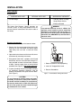
WARNING
To assure proper operation and avoid a
possible unsafe condition, the booster heater
must be installed in a horizontal position with
the base parallel to the floor and the inlet
connection at the lowest point.
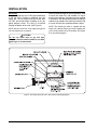
The Booster Heater must not be installed directly on
carpeting, but on top of a metal, wood (or
equivalent) panel extending beyond the full width
and depth of the booster heater by at least 3"
(76 mm) in any direction or, if the heater is installed
in an alcove, the entire floor must be covered by the
panel. The panel must be strong enough to carry the
weight of the heater when full of water.
NOTE: In the Commonwealth of Massachusetts,
Hatco Booster Heaters shall be installed by a
licensed plumber and gasfitter.
NOTE: The Commonwealth of Massachusetts
requires that if a water treatment system is
installed in line with the Hatco Booster Heaters,
a water backflow protector shall also be
installed.
Adequate front clearance is required to allow for
accessibility to the control compartment.
NOTE: If a check valve or water backflow protector
is installed and cannot be removed install a back
pressure relief valve, Hatco part number
03.02.039.00, set at 125 psi (862 kPa) on the
incoming line between the pressure reducing valve
and the inlet to the booster heater. Discharge must
be to open site drain.
The booster heater should be located in an area
where leakage of the tank or connections will not
result in damage to the area adjacent to the heater
or to lower floors of the structure. When such
locations cannot be avoided, it is recommended that
a suitable drain pan, adequately drained, be
installed under the booster heater. The pan must not
restrict combustion air flow.
For the most effective operation, install the Hatco
Gas Booster Heater as close as possible to the
dishwashing machine.
NOTE: Employ external recirculation if distance
between booster and dishwasher exceeds the
National Sanitation Foundation specifications of five
(5) feet (1.5 m).
7
Form No. PMG-100/200M-0805
INSTALLATION
Combustion/Ventilation Air
The booster heater must be located in an area
which allows for an adequate supply of air for proper
combustion and ventilation in accordance with
Section 5.3 and 7.2.2 of the National Fuel Gas Code
NFPA54/ANSI Z223.1 or applicable provisions of
the local building codes. Only a single booster
appliance may be installed in this manner.
Installations under the jurisdiction of Canadian
CSA-B149.1, Natural Gas and Propane
Installation Code, require a gas interlock tied
into the ventilation hood system. {Les
installations sous la juridiction des CODES
D’INSTALLATION
canadiens
CSA-B149.1,
Natural Gas and Propane Installation code,
nécessitent un verrouillage réciproque de gaz
raccordé au système de capot de ventilation.}
Form No. PMG-100/200M-0805
WARNING/CAUTION
The flow of air to the heater for combustion
and ventilation must not be obstructed. Air
vents on the bottom and side of the unit
should never be blocked. All panels should be
in place during normal operation for optimal
performance and safety.
WARNING/CAUTION
This unit is designed to vent to the outside or
into an open Equipment Hood, and is intended
for commercial food service water heating
only. IT IS NOT FOR RESIDENTIAL USE. See
VENT section of this manual.
WARNING/CAUTION
Flue gases exit top side or back of this unit and
must not be obstructed, specified clearances
must be maintained for safe operation. See
VENT section for vent piping alternatives.
8
INSTALLATION
Minimum Clearance Requirements: {Exigences quant au dégagement minimum:}
Floor
{Sol}
Top
{Dessus}
Left Side
{Côté gauche}
Right Side
{Côté droit}
Front
{Devant}
Back
{Derrière}
6"* (152 mm)
1" (25 mm)
2" (51 mm)
2" (51 mm)
20" (508 mm)
2" (51 mm)†
* Includes legs supplied with booster heater {Comrend pieds fournis avec appareil de chauffage auxiliare}.
† Minimum clearance of 8" (203 mm) from the side of the appliance where the vent is installed.
High Altitude Installation and Operation
Atmospheric conditions at elevations above 2000 ft.
(610 m) have an effect on the performance of most
gas fired products. For this reason, historical models
for altitude de-rating were developed for gas
appliances with atmospheric burners. The National
Fuel Gas Code, ANSI Z223.1 is an accepted model
which requires a de-rating of 4% per 1000 ft.
(305 m) elevation when no testing to the contrary
exists for that product. This could require modifying
the equipment and adjusting settings in the field to
achieve de-rating. Testing has shown this to be a
very conservative approach.
• PMG-200 will require orifice changes at levels
shown in the Altitude Summary chart. This
follows the 4% de-rating scheme outlined in
ANSI Z223.1 for both natural gas and liquid
propane gas. Also note that the GPH capacity
will be reduced and a guideline is given as to the
percent of sea level capacity expected.
For Canadian installations between 2000-4500 feet
(610-1370 m) de-rate unit by 10% to 175,500 BTU.
Manufacturers discourage unnecessary field
adjustments in order to maintain a level of
performance and quality designed into the product.
For these and other reasons, testing was
underwritten through CSA International to verify an
improved satisfactory performance with little or no
modification to effect input rate or control. The
following text and charts are a result of this testing
and should be used during application sizing and
installation.
Orifice Kits for altitude installations may be ordered
through Hatco Customer Service. Please call for
orifice sizing information.
{Pour les installations au Canada entre 610 et
1370 m (2000 et 4500 pi) reclassifier l’appareil de
10% à 175 500 BTU}
• The PMG-100 can operate at better levels than
ANSI Z223.1 without manifold pressure setting
adjustments or orifice changes up to the 8500 ft.
(2593 m) elevation for both natural gas and liquid
propane gas units. Above this level only a slight
decrease in manifold pressure may be needed to
meet the approved BTU rate. This is shown in
the Altitude Summary chart. Also, note that GPH
capacity will be reduced and a guideline is given
as to the percent of sea level capacity expected.
For Canadian installations between 2000-4500 feet
(610-1370 m) de-rate unit by 10% to 94,500 BTU.
{Pour les installations au Canada entre 610 et 1370
m (2000 et 4500 pi) reclassifier l’appareil de 10% à
94 500 BTU.}
9
Form No. PMG-100/200M-0805
INSTALLATION
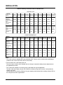
Altitude Summary Publication Data for PMG Boosters
NATURAL GAS
Altitude:
Ft. Above Sea Level
(Meters)
0-2000
(0-610)
2001-3000 3001-4000 4001-5000 5001-6000 6001-7000 7001-8000 8001-8500 8501-9500 9501-10500
(610-915) (915-1220) (1220-1525) (1525-1830) (1830-2135) (2135-2440) (2440-2593) (2593-2898) (2898-3203)
PMG-100
Approved
Input Rate*
105000 103363
Suggested Orifice
#34DMS #34DMS
Size†
GPH Capacity
De-Rate•
1
0.98
101726
100089
98452
96815
95178
94360
90585
86811
#34DMS
#34DMS
#34DMS
#34DMS
#34DMS
#34DMS
#34DMS
#34DMS
0.97
0.95
0.94
0.92
0.91
0.90
0.86
0.83
156000
148200
140400
132600
128700
123552
118404
#37DMS
#37DMS
#38DMS
#39DMS
#40DMS
#41DMS
#42DMS
0.80
0.76
0.72
0.68
0.66
0.63
0.61
PMG-200
Approved Input
Rate*
195000 171600
163800
Suggested Orifice
#35DMS # 3 6 D M S # 3 6 D M S
Size†
GPH Capacity
De-rate•
1
0.88
0.84
LIQUID PROPANE GAS
Altitude:
Ft. Above Sea Level
(Meters)
0-2000
(0-610)
2001-3000 3001-4000 4001-5000 5001-6000 6001-7000 7001-8000 8001-8500 8501-9500 9501-10500
(610-915) (915-1220) (1220-1525) (1525-1830) (1830-2135) (2135-2440) (2440-2593) (2593-2898) (2898-3203)
PMG-100 LPG
Approved
Input Rate*
105000 102937
Suggested Orifice
#50DMS #50DMS
Size†
GPH Capacity
De-Rate•
1
0.98
PMG-200 LPG
Approved Input
Rate*
195000 171600
Suggested Orifice
#50DMS #51DMS
Size†
GPH Capacity
De-rate•
1
0.88
100874
98810
96747
94684
92621
91589
87925
84262
#50DMS
#50DMS
#50DMS
#50DMS
#50DMS
#50DMS
#50DMS
#50DMS
0.96
0.94
0.92
0.90
0.88
0.87
0.84
0.80
163800
156000
148200
140400
132600
128700
123552
118404
#51DMS
#51DMS
#51DMS
#52DMS
#52DMS
#52DMS
#53DMS
#53DMS
0.84
0.80
0.76
0.72
0.68
0.66
0.63
0.61
Notes:
* This is the maximum allowable BTU rate certified by CSA. These are to be verified by the qualified gas
installer on site. Check Heat Value with local Gas Utility
† The first orifice size is the factory built unit.
The next sizes are shown at the altitudes where a change is required to allow pressure adjustments to
the approved input rates.
• This is a de-rate multiplier to use when sizing a gas booster for a given application.
Take this value and multiply it by the GPH found on the Hatco sizing chart to ensure it will provide the
capacity you need.
You can also use this value by dividing it into your capacity needs and take the resulting adjusted GPH to
the sizing chart to select a gas booster.
Form No. PMG-100/200M-0805
10
INSTALLATION
PLUMBING
Components
SUPPLIED WITH UNIT
• Temperature/Pressure
Relief Valve
• Blended Phosphate Water
Treatment System
• Pressure Reducing Valve
• Temperature/Pressure Gauges (2)
• Shock Absorber
• 3/4" Plug (installed)
OPTIONAL WITH UNIT
SUPPLIED BY INSTALLER
• Back Pressure Relief
Valve
• 3/4" Gate or Ball Valve
• Drain Valve
• 3/4" Unions
• 3/4" Piping
Pressure And Temperature Relief Valves
For protection against excessive pressures and
temperatures in the booster heater, install
temperature and pressure protective equipment by
local codes. Hatco supplies valves constructed with
brass working parts and heat resistant silicone seat
discs for all booster heater models.
CAUTION
FOR
INSTALLING
PRESSURE
AND
TEMPERATURE
RELIEF
VALVES
IN
ACCORDANCE WITH ANSI Z21.22*CSA 4.4.
Combination pressure and temperature relief
valves with extension thermostats must be
installed so that the temperature-sensing
element is immersed in the water within the top
6" (152 mm) of the tank. They must be installed
either in the hot outlet service line or directly in
a tank tapping. Combination pressure and
temperature relief valves that do not have
extension elements must be mounted directly
in a tank tapping located within the top 6"
(152 mm) of the tank, and shall be adequately
insulated and located so as to assure isolation
from flue gas heat or other ambient conditions
that are not indicative of stored water
temperature. TO AVOID WATER DAMAGE OR
SCALDING DUE TO VALVE OPERATION,
DRAIN PIPE MUST BE CONNECTED TO VALVE
OUTLET AND RUN TO A SAFE PLACE OF
DISPOSAL. Drain pipe must be as short as
possible and be the same size as the valve
discharge connection throughout its entire
length. Drain line must pitch downward from
the valve and terminate at least 6" (152 mm)
above the floor drain where any discharge will
be clearly visible. The drain line shall terminate
plain, not threaded, with a material serviceable
for temperatures up to 250°F (121°C) or
greater. Excessive length, over 15' (4.57 m), or
use of more than two elbows can cause a
restriction and reduce the discharge capacity
of the valve. No shut-off valve shall be installed
between the relief valve and tank, or in the
drain line. Valve lever must be tripped
periodically to ensure that waterways are clear.
This device is designated for emergency
safety relief and shall not be used as an
operating control. The valves are set to relieve
at 150 pounds pressure or when water
temperature reaches 210°F (99°C). Read tag on
valve for additional information.
WARNING
Valves supplied by Hatco are designed for high
temperature commercial operation. Do not
substitute Hatco valves with valves designed
for domestic water heaters.
Temperature/pressure protective equipment
should not be less than a combination
temperature/pressure relief valve certified by a
nationally recognized testing laboratory that
maintains periodic inspection of the
production of this equipment and meets the
requirements for Relief Valves and Automatic
Shutoff Devices for Hot Water Supply Systems,
ANSI
Z21.22*CSA
4.4.
The
temperature/pressure relief valve must be
marked with a minimum set pressure not to
exceed the marked maximum working
pressure of the booster heater.
CAUTION
Do not use an anti-siphon or check valve on
the incoming water line.
NOTE: If a check valve or water backflow protector
is installed and cannot be removed install a back
pressure relief valve, Hatco part number
03.02.039.00, set at 125 psi (862 kPa) on the
incoming line between the pressure reducing valve
and the inlet to the booster heater. Discharge must
be to open site drain.
11
Form No. PMG-100/200M-0805
INSTALLATION
Temperature/Pressure Gauges
Hatco requires a temperature/pressure gauge be
installed in both the inlet and outlet lines to the
booster heater. These gauges provide an instant
visual check of the water temperature and pressure
entering and leaving the booster heater. The visual
check is helpful in eliminating unnecessary service
calls.
Install the temperature sensing bulb in the water
system. See Figures 2 and 3 for methods of
installation.
Pressure Reducing Valve
Proper operation of most dishwasher rinse nozzles
require available water flow pressure at the nozzle
to be 20 PSI.
Figure 2. Installation Temperature/Pressure Gauge
If water pressure available to the booster heater
inlet is over 20 PSI, a pressure reducing valve with
bypass must be installed in the hot water supply line
to the booster heater.
The valve supplied by Hatco has a built-in high
pressure bypass which prevents excessive pressure
build-up as the booster heats up.
CAUTION
Pressure regulating valve must have a built-in
high pressure bypass.
Figure 3. Installation Temperature/Pressure Gauge
Blended Phosphate Water Treatment System
Hatco requires that the Blended Phosphate Water
Treatment System supplied be installed with unions
on the incoming 3/4" water supply line after the
pressure reducing valve and before the booster
heater.
NOTE: If a check valve or water backflow protector
is installed and cannot be removed install a back
pressure relief valve, Hatco part number
03.02.039.00, set at 125 psi (862 kPa) on the
incoming line between the pressure reducing valve
and the inlet to the booster heater. Discharge must
be to open site drain.
Cartridges supplied have a usage rating of 100,000
gallons of water. To ensure proper operation the
cartridges must be replaced when expired.
NOTE: Product failure caused by liming or sediment
buildup is not covered under warranty.
NOTE: The Commonwealth of Massachusetts
requires that if a water treatment system is
installed in line with the Hatco Booster Heaters,
a water backflow protector shall also be
installed.
Form No. PMG-100/200M-0805
12
INSTALLATION
PLUMBING CONNECTIONS (See Figure 4)
Inlet
Hatco Booster Heaters are designed to be
connected with 3/4" pipe at the inlet pipe from the
primary water heater. Water temperature from the
primary water heater must be at least 110°F (43°C)
and should not exceed 160°F (71°C). Minimum
temperature differential between the inlet and outlet
temperature must never be less than 20°F (11°C).
CAUTION
To avoid development of a leak, do not back
up or loosen any water pipe fittings.
WARNING
Do not connect the heater directly to a boiler
or furnace coil or any other uncontrolled
temperature source. Such hook-up could
cause the thermostat to lose control and the
unit could overheat.
NOTE: Refer to BOOSTER HEATER SIZING
CHART for application information.
Inlet line must be installed with a shut-off valve, a
full open gate or ball type valve, a 3/4" union,
together with the blended phosphate water
treatment system, pressure reducing valve set at
20 PSI (1.4 kg/cm2) flow pressure and a
temperature/pressure gauge supplied by Hatco.
NOTE: Do not run a cold ground water line to the
Booster Heater.
CAUTION
Incoming water supply in excess of 3 grains of
hardness per gallon ([GPG] .75 grains of
hardness per liter [GPL]) must be
treated/softened before being supplied to
booster heater(s). Water that contains over
3 GPG or .75 GPL will decrease efficiency and
reduce the operating life of the unit.
NOTE: Product failure caused by liming or
sediment buildup is not covered under
warranty.
CAUTION
Incoming water supply to booster heater must
be a minimum of 20 psi, (1.4 kg/cm2) water
pressure less than 20 psi (1.4 kg/cm2) will
decrease the operating life of the recirculating
pump and the unit.
NOTE: Product failure caused by incoming
water pressure less than 20 psi (1.4 kg/cm2) is
not covered under warranty.
13
Form No. PMG-100/200M-0805
INSTALLATION
NOTE: Be sure water flows through the pressure
reducing valve in the proper direction. Check the
directional arrow. Valve will reduce pressure only
during flow conditions.
To prevent water leakage and damage to the unit,
the location for the temperature/pressure relief valve
that is not used must be plugged. (One plug is
supplied by Hatco with the heater.) Both
temperature/pressure fittings MUST NOT be
plugged.
A 3/4" union fitting and a drain valve must also be
installed to allow for easy servicing.
The temperature/pressure relief valve must be
installed into one of two locations on the heater:
either the right side or the back of the unit. See
Figure 4 for exact locations.
†NOTE: The Commonwealth of Massachusetts
requires that if a water treatment system is
installed in line with the Hatco Booster Heaters, a
water backflow protector shall also be installed.
*Not Supplied With Booster Heater
Optional Accessory
Figure 4. Plumbing Connections – PMG-100/200 Gas Booster Heaters
Form No. PMG-100/200M-0805
14
INSTALLATION
†NOTE: The Commonwealth of Massachusetts
requires that if a water treatment system is
installed in line with the Hatco Booster Heaters, a
water backflow protector shall also be installed.
*Not Supplied With Booster Heater
Optional Accessory
Figure 5. PMG-100/200 Gas Booster Heaters Connected in Series
Outlet
Using a 3/4" union and piping, connect the booster
heater water outlet to the dishwasher sanitizing
rinse pipe connection.
Shock Absorber
In areas of high water pressure, Hatco recommends
a shock absorber be installed in the outlet line as
close as possible to the dishwasher. The shock
absorber softens the water hammer caused by
automatic dishwasher valves. (See Figure 4.)
NOTE: Be certain the connection is made to the final
rinse and not to the wash tank.
NOTE: Fill booster heater with water to test for
installation leaks. Leave the water in booster to
prevent pump damage in the event the electrician
should apply power.
Install a temperature/pressure gauge in outlet line.
Water temperature at outlet should be 180°F
(82°C).
NOTE: The temperature sensing element must be in
water stream. (See Figures 2 and 3.)
GAS
Components
SUPPLIED WITH UNIT
• Internal Gas Valve (installed)
OPTIONAL WITH UNIT
None
• External Gas Shutoff Valve (loose)
SUPPLIED BY INSTALLER
• Gas Supply Line
• Sediment Trap
• Union
• Vent System
15
Form No. PMG-100/200M-0805
INSTALLATION
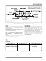
Gas Piping
The gas inlet pipe size is 3/4" NPT pipe thread fitting
to the gas valve. Provide an adequate size gas
supply line. The line should never be smaller than
3/4" NPT and should follow according to the gas
piping diagram below. The fitting is accessed
through the bottom of the case. (See Figure 6.)
Gas line should be kept as short as possible, sized
to furnish the rated BTU, and installed in a way to
protect it from damage. Gas piping must be installed
in accordance with local plumbing codes including a
sediment trap, ahead of the heater gas controls and
a manual shut-off valve located outside the jacket.
NOTE: The internal gas valve is supplied with the
heater, the external manual gas valve supplied with
unit must be plumbed in by the installer. See Figure
6 for gas piping diagram.
NOTE: Gas line should be of the approved type for
use with natural gas or propane.
CAUTION
Do not use Teflon tape on gas line pipe
threads. A flexible sealant suitable for use with
applied gas is recommended.
Figure 6. Gas Hook-up and Pressure Tap Location and Piping Diagram.
Form No. PMG-100/200M-0805
16
INSTALLATION
Incoming Gas Pressure Specifications
WARNING/CAUTION
The gas used with this unit must be the type
specified on the spec plate on this unit. To
avoid personal injury or damage to the unit,
never use any other than the specified gas.
Inches Water Column
Gas Type
The heater and its gas connection must be leak
tested before placing the booster heater in
operation.
Minimum
Maximum
Natural
5.0
10.5
Propane/LP
11.0
13.0
The maximum inlet gas pressure must not exceed
the values shown above. The minimum gas
pressure listed is for the purposes of input
adjustment.
The booster heater and its individual shut-off
valve must be disconnected and isolated from
the gas supply piping system during any
pressure testing of the system at test
pressures in excess of 1/2 PSI (3.5 kPa.).
The manifold inside the heater is provided with a
pressure tap to measure the gas pressure. The
chart below lists the proper pressure amounts at the
manifold pressure tap when testing.
This appliance must be isolated from the gas
supply piping system by closing its individual
manual shutoff valve during any pressure
testing of the gas supply piping system at test
pressures equal to or less than 1/2 psig
(3.5 kPa).
Operating Pressure Specifications at Manifold
Inches Water Column At Pressure Tap
Gas Type
Dissipate test pressure from the gas supply
line before re-connecting the heater and its
manual shut-off cock to the gas supply line.
FAILURE TO FOLLOW THIS PROCEDURE MAY
DAMAGE
THE
GAS
VALVE.
OVER
PRESSURED GAS VALVES ARE NOT
COVERED BY THE WARRANTY.
High Burn
Natural
3.5
Propane/LP
10.0
See Figure 6 for hook-up location and pressure tap
location.
The heater and its gas connections shall be
leak tested before placing the appliance in
operation. Use soapy water or commercially
available fluid for leak test. DO NOT use open
flame to test for leaks.
17
Form No. PMG-100/200M-0805
INSTALLATION
ELECTRICAL
Components
SUPPLIED WITH UNIT
OPTIONAL WITH UNIT
SUPPLIED BY INSTALLER
None
• 120 VAC, 60 Hz, 15 Amp
Single Phase Service
• 7/8" Hole Plugs
• Electrical Ground
The Hatco Gas Booster Heater operates on
120 VAC, 60 Hz, 15 amp, single phase service. All
internal electrical connections have been made at
the factory.
WARNING
If an external electrical source is utilized, the
appliance, when installed, must be electrically
grounded in accordance with local codes, or,
in the absence of local codes, with the National
Electrical Code, ANSI/NFPA 70, and CSA C22.1,
Electrical Code.
Electrical Connections
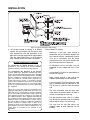
To connect the field wiring to the booster heater:
1. Remove the front access panel from the unit by
lifting up on the front panel and pulling upper
edge away from unit until it clears the lower
edge.
2. Open electrical enclosure at the lower left corner
of the base by removing two screws.
3. Bring power leads from a properly sized fused
disconnect switch or circuit breaker through 7/8"
hole provided on lower left hand side or bottom
of base. Connect supply lines to terminal block
provided. (See Figure 7.) Use copper wire only.
1. Rotate Screwdriver into top opening.
2. Insert 3/8" Stripped Wire Lead.
4. A green grounding terminal is provided internally.
An equipment grounding conductor must be
properly connected to the green terminal block.
(See Figure 7.)
3. Remove Screwdriver.
Figure 7. Terminal Block Wiring Instructions.
CAUTION
To avoid damage to both the pump and heater
assembly, do not turn on the power switch to
the heater until the installation is complete and
the booster water tank is filled with water and
all air in the system has been vented through
the dishwasher rinse nozzles.
Form No. PMG-100/200M-0805
18
INSTALLATION
b. Horizontally vented through an outside wall
directly to the outdoors. See additional
instructions below. (See Figure 9.)
VENTING
The PMG-100 and PMG-200 may be vented by two
methods, both of which have been tested for
compliance with national safety standards for gas
water heaters. Whichever method is used must
comply with local codes. The installation of the
venting system must comply with local codes and in
the absence of local codes, in accordance with the
National Fuel Gas Code and the guidelines in this
manual. Before installing any method of venting
you should contact the local code authority of
your gas supplier to make sure that the final
installation will be acceptable to the authorities
having jurisdiction.
c. Exhausted into a vertical masonry chimney
that has a listed steel liner installed in the
chimney. Locate appliance as close as
practicable to a chimney or gas vent.
Because of the low flue gas temperature, do
not vent into an unlined or masonry lined
chimney. Note that all venting into a vertical
chimney of any type must comply with the
horizontal and vertical ratios and sizing
requirements that are detailed in the National
Fuel Gas Code.
The proper method of venting a power vented gas
appliance is too complicated to cover in this manual
and is explained in detail in the National Fuel Gas
Code. Before installing the venting system the
person or agency making the installation must be
familiar and experienced with the guidelines of the
National Fuel Gas Code.
d. Vented vertically using type B vent pipe that is
5" (127 mm) in diameter provided the
termination above the roof uses a listed wind
cap.
1AL
29-4C is a Registered Trademark of Allegheny Ludlum
Corp.
The temperature of the flue gases from this booster
water heater operates at approximately 225°F to
275°F (107°C to 135°C).
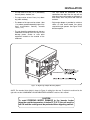
The two methods that have been tested for
compliance with the national safety standards are:
1. The first method of venting permits the
connection of 4" (102 mm) diameter, AL 29-4C1
stainless steel vent pipe. Use only the specific
types of materials currently listed by a nationally
recognized testing agency for category III
venting. The maximum combined horizontal
vent length must not exceed a length of
40 feet (12 m) [each sweep elbow is the
equivalent of 5' (1.5 m) of straight pipe and a
standard right elbow is the equivalent of
10 feet (3 m)]. The venting may be done in such
a way that the exhaust products are:
a. Conveyed to another area in the kitchen such
as under a ventilator or near an exhaust fan
(both of which exhaust outdoors).
(See Figure 8.)
When using this method the booster water
heater must be electrically interlocked with
the vent hood to prevent operation if the vent
hood is not operating.
Figure 8. Venting Through Typical Exhaust System.
The termination end must be placed so that it
vents above the bottom of the hood skirt. Do
not penetrate the filter with the vent.
19
Form No. PMG-100/200M-0805
INSTALLATION
Figure 9. Typical Through-the-Wall Venting
General Notes On Venting:
2. The second method of venting is to directly
exhaust the flue products into the kitchen work
area provided the size and installation of the
open room meet the requirements of the National
Fuel Gas Code [ANSI Z223.1 or NFPA bulletin
#54]. A portion of the 1996 code is as follows.
• Whenever a vent pipe goes through a
combustible wall, the clearance between the
vent material and the combustible material
must be in accordance with the listing
requirements of the vent system chosen. See
the vent manufacturer’s instructions.
EXCERPT FROM ANSIZ223.1/NFPA #54
• All horizontal runs of vent pipe must be
supported at every elbow and every 3 feet
(1 m).
7.2.1 Connection To Venting Systems. Excerpt as
permitted in 7.2.2 through 7.2.6, all gas utilization
equipment shall be connected to venting systems.
7.2.2 Equipment Not Required To Be Vented.
A single booster-type [automatic instantaneous] water
heater, when designed and used solely for the sanitizing
rinse requirements of a dishwashing machine, provided
that the equipment is installed, with the draft hood in
place and unaltered, if a draft hood is required in a
commercial kitchen having a mechanical exhaust
system. Where installed in this manner, the draft hood
shall not be less than 36 inches (91 cm) vertically and 6
inches (15 cm) horizontally from any surface other than
the equipment.
• All horizontals must have an upward pitch of
at least 1/4" per foot.
• When venting through a side wall to the
outdoors the following must be observed:
• A vent termination [Tee Fitting] must be used
that is positioned with the backside of the
TEE at least 12" (305 mm) from the exterior
wall.
Where any or all of this equipment is installed so the
aggregate input rating exceeds 20 Btu per hr per cu ft
(207 watts per m3) of room space in which it is installed,
one or more shall be provided with venting systems or
other approved means for removing the vent gases to
the outside atmosphere so the aggregate input rating of
the remaining unvented equipment does not exceed the
20 Btu per hr per cu ft (207 watts per m3) figure. Where
the room or space in which the equipment is installed is
directly connected to another room or space by a
doorway, archway, or other opening of comparable size
that cannot be closed, the volume of adjacent room or
space shall be permitted to be included in the
calculation.
Form No. PMG-100/200M-0805
• The vent termination must be away from
areas where the general public will walk or
vehicle may damage the vent cap.
• The cap must be at least 3 feet (1 m) above
any forced inlet openings [into the building]
that are within 10 feet (3 m) of the cap.
• The cap must be one foot above any
windows, doors or other openings into the
building.
20
INSTALLATION
• The cap must be 4 feet (1.2 m) horizontally
from any doors, windows, etc.
• The cap must be at least 7 feet (2 m) above
any public walkway.
• The cap should be positioned so that
condensate that drips from the cap will not
allow the water to accumulate on walkways or
other areas, which may freeze and cause an
accident.
• The bottom of the cap must be at least 1 foot
(.3 m) above ground and possibly higher if the
snow accumulation normally exceeds
1 foot (.3 m).
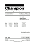
• Right angle adapter is provided to minimize
radius of initial bend toward flue piping
required for tight quarters. See Figure 10 for
direction options.
• The cap should be positioned such that any
condensate that drips from the cap will not
damage plants, shrubs or onto other
equipment located on the outside of the
restaurant.
Figure 10. Right Angle Adapter Mounting Options.
NOTE: The standard Vent Outlet is shown in Figure 10 exiting from the rear. To adjust the outlet exit to the
right side see the COMPONENT-ADJUSTMENT/REPLACEMENT section of this manual.
CAUTION
To avoid FREEZING WATER DAMAGE to the booster heater
when the outside temperature is below 32°F (0°C) the unit must be
left ON and the venting must be protected from migrating cold air.
21
Form No. PMG-100/200M-0805
OPERATION
1. This appliance is equipped with an ignition
device which automatically lights the pilot. DO
NOT TRY TO LIGHT THE PILOT BY HAND.
START UP PROCEDURES
NOTE: Remove the front access panel during start
up.
Filling The System With Water
1. With the external gas supply and electric
supply turned off, close the drain pipe valve.
2. BEFORE OPERATING smell all around the
appliance area for gas. Be sure to smell next to
the floor because some gas is heavier than air
and will settle on the floor.
NOTE: Water temperature at the inlet should be
between 110°F (43°C) and 150°F (66°C) and should
never exceed 160°F (71°C) for the unit to operate
properly and meet the demands of the dishwashing
machine. Minimum temperature differential between
inlet and outlet temperatures should never be less
than 20°F (11°C).
What To Do If You Smell Gas:
• Do not try to light any appliance.
• Do not touch any electric switch; do not use
any phone in your building.
NOTE: Do not run a cold ground water line to the
Booster Heater(s).
• Immediately call your gas supplier from a
neighbor’s phone. Follow the gas supplier’s
instructions.
CAUTION
Incoming water supply in excess of 3 grains of
hardness per gallon ([GPG] .75 grains of
hardness per liter [GPL]) must be
treated/softened before being supplied to
booster heater(s). Water that contains over
3 GPG or .75 GPL will decrease efficiency and
reduce the operating life of the unit.
NOTE: Product failure caused by liming or
sediment buildup is not covered under
warranty.
2. When the water tank is full, turn on the electric
supply and the power switch to allow the
circulator pump to purge air from it. The circulator
pump should start immediately. Additional air in
the tank can be vented through the dishwasher
rinse nozzle.
• If you cannot reach your gas supplier, call the
fire department.
3. Use only your hand to push in or turn the gas
control knob. Never use tools. If the knob will not
push in or turn by hand, don’t try to repair it - call
a qualified service technician. Force or
attempted repair may result in a fire or explosion.
4. Do not use this appliance if any part has been
under water. Immediately call a qualified service
technician to inspect the appliance and to
replace any part of the control system and any
gas control which has been under water.
NOTE: Dishwasher should be cycled a minimum of
three times before the gas supply to the booster is
turned on.
Operating Instructions:
Les Instructions quant a la nise en service de ce
chauffe-eau se trouvent sur la surface interieure du
ponneau avant. Pour retirer le panneau, saisar les
cotes avont interieurs du panneau avant et soulever
vers le haut, tirer le bord inferieur vers l’exterieur et
laisser le bord superieur tomber.
3. After all the air has been vented out of the
system, turn off the power to the booster
heater.
CAUTION
Product failure caused by dry firing is not
covered under warranty.
WARNING/CAUTION
Should overheating occur or the gas supply
fail to shut off, turn off the manual gas control
valve to the appliance.
Lighting The Heater
FOR YOUR SAFETY, READ BEFORE OPERATING:
WARNING
If you do not follow these instructions exactly,
a fire or explosion may result, causing
property damage, personal injury or loss of
life.
En cas de surchauffe ou si l’alimentation en
gaz ne s’arrête pas, fermez manuellement le
robinet d’arrêt de l’admission de gaz.
AVERTISSEMENT: Assurez-vous de bien
suivre les instructions données dans cette
notice pour réduire au minimum le risque
d’incendie ou d’explosion ou pour éviter tout
dommage matériel, toute blessure ou la mort.
Form No. PMG-100/200M-0805
22
OPERATION
1. STOP! Read the safety information on the
appliance label or in this manual.
2. Turn off all electric power to the appliance.
3. This booster heater is equipped with an ignition
device which automatically lights the pilot. DO
NOT try to light the pilot by hand.
4. To gain access to controls remove front panel by
sliding it up and pulling lower edge out and down
away from the appliance.
5. Turn gas control knob clockwise to OFF.
(See Figure 11.)
6. Wait five (5) minutes to clear out any gas. If you
smell gas STOP! Follow “B” in the safety
information under Start Up Procedures. If you do
not smell gas, continue to the next step.
Figure 11. Gas Valve - Top View
To Turn Off Gas To Appliance:
1. Turn off power switch on heater.
7. Turn gas control knob counterclockwise to ON.
8. Replace front access panel.
9. Turn on all electric power to the appliance.
2. Turn off all electric power to the appliance if
service is to be performed.
10.Turn on power switch and:
3. Shut off external manual gas valve.
a. After approximately 20 seconds the ignition
sequence should begin and light the pilot. If
the water temperature is below the setpoint
the heating process will start.
4. Remove front cover of heater for access to the
control compartment.
5. Turn gas control knob clockwise to OFF.
Do not force.
b. Allow the booster heater to run until the
burner shuts down. The booster heater is now
at
its
setpoint,
stabilized
working
temperature.
6. Replace front access panel.
CAUTION
To avoid FREEZING WATER DAMAGE to the
booster heater when the outside temperature
is below 32°F (0°C) the unit must be left ON and
the venting must be protected from migrating
cold air.
c. Run the dishwashing machine through at
least two rinse cycles. After the first rinse
cycles. After the first rinse cycle the burner
should re-light and remain lit until the water
maintains 180°-185°F (82°-85°C) output @
20 psi through the second cycle.
NOTE: If this test does not proceed as
described, contact the Hatco Corporation or
your authorized service agent for technical
assistance.
11. If the appliance will not operate, follow the
instructions “To Turn Off Gas To Appliance” and
call your service technician or gas supplier.
23
Form No. PMG-100/200M-0805
MAINTENANCE
6. The front access panel should be removed and
all components visually inspected at least twice a
year. Check for evidence of chafing or heat
damage to any wiring or components. Check
also for any signs of water leakage at any of the
plumbing connections. If there are signs of any
damage or leakage contact the Hatco
Corporation or your authorized service agent.
CAUTION
Using or storing chlorine based products on
or near the booster heater may shorten the life
of the unit and void the product warranty.
NOTE: Refer to the REPLACEMENT PARTS LIST
for exploded views, part identification and location.
NOTE: Refer to the WIRING DIAGRAM for specific
electrical information.
7. The relief valve should be manually operated at
least once a year to ensure proper operation.
GENERAL
WARNING
Before performing this operation, care should
be taken that any of the discharged water does
not come into contact with the operator or
surrounding surfaces. The water can be
extremely hot and can cause severe scalding
and damage to the property.
1. Keep the area around the heater free and clear
of debris and flammable materials. Do not block
air intakes or vents.
2. The recirculating water pump motor is
permanently lubricated and requires no other
maintenance.
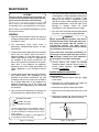
3. Visually observe and inspect the burner and pilot
flame every six months. When the burner is
operating properly a clean blue flame will be
visible. (See Figures 12 and 13.) Depending on
the condition of the kitchen environment, the
burner may need to be cleaned of lint or greaseladen dust. If any problems are apparent,
discontinue use of the heater and contact the
Hatco Corporation or your authorized service
agent.
If the relief valve discharges periodically, do
not plug it. If replacing the valve does not stop
the discharge, contact your local authorized
service agent or the Hatco Corporation.
8. Visually observe and inspect the Blended
Phosphate Water Treatment System weekly: To
ensure proper operation replace depleted
cartridges immediately.
BURNER REMOVAL/INSPECTION
4. Visually observe and inspect the heat exchanger
and exhaust blower fan. Depending on the
condition of the kitchen environment, the heat
exchanger and fan may need to be cleaned of
lint or grease laden dust. If any problems are
apparent, discontinue use of the heater and
contact the Hatco Corporation or your authorized
service agent.
(TO BE PERFORMED BY YOUR AUTHORIZED
SERVICE AGENCY)
1. Shut-off the electrical power and gas supply
to the heater.
2. Disconnect the internal flexible gas supply line
connector at the gas regulator valve.
3. Disconnect the ignition module spark cable.
4. Remove two nuts holding the burner tray to the
base.
5. Once a month check and clean (if necessary) all
air inlet holes on the side or back of the unit.
5. Remove four screws from the front cover of the
combustion chamber and remove the cover.
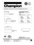
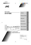
Broad Blue Outer Flame
Light Blue Inner Cone
Slotted Burner Element
3/8-1/2"
• The flame during full burn is a broad blue color. An
inner cone slightly lighter in color will also be visible.
• The flame should not be rising off of the face of the
burner element.
• Yellow tipped flames suggest a need for adjustment
or cleaning of the burner assembly.
Figure 13. Pilot Flame.
Figure 12. Gas Flame.
Form No. PMG-100/200M-0805
24
MAINTENANCE
6. Lift and slide burner assembly out.
WARNING
Label all wires prior to disconnection when
servicing controls. Wiring errors can cause
improper and dangerous operation. Verify
proper operation after servicing.
7. Disconnect spark electrode wire from pilot
igniter.
8. Perform intended service.
9. Reverse above procedure to re-install, checking
burner assembly and seal to prevent gas
leakage.
ATTENTION
Au moment de l’entretien des commandes,
étiquetez tous les fils avant de les débrancher.
Des erreurs de câblage peuvent entrâiner un
fonctionnement inadéquat et dangereux.
DRAINING THE HEAT EXCHANGER
1. Shut-off the electrical power, gas and water
supply to the heater.
S’assurer
que
l’appareil
fonctionne
adéquatement une fois l’entretien terminé.
2. Allow unit to cool down to room temperature.
1. Gas Valve Replacement
a. Shut off electrical power and gas supply to
the heater.
b. Remove front panel.
c. Remove flexible gas piping to gas valve inlet.
d. Disconnect wiring connections to gas valve.
e. Remove burner tray assembly as outlined
above.
f. Remove valve from manifold pipe.
g. Reverse above procedure to re-install,
checking burner and seals to prevent gas
leakage.
3. Open the drain valve under the booster heater to
remove water from the tank and pump assembly.
4. Remove the drain plug located on the front of the
heat exchanger and allow the water to drain from
the heat exchanger into a pan or pail.
Approximately 16 oz. (498 g) of water will drain
from the unit.
5. Reverse above procedure using a food grade
thread sealant to seal the plug threads and
prevent leakage.
2. Ignition Module Replacement
a. Shut off electrical power to the booster.
b. Disconnect spark plug igniter wire.
c. Remove mounting screws holding module.
d. Remove module.
e. Reverse above procedure to re-install.
3. Transformer Replacement
a. Shut off electrical power to the heater.
b. Remove screws from electrical box and lift
off.
c. Disconnect wire leads from transformer at the
power supply. (See Figure 9.)
d. Remove mounting screws that hold
transformer in place.
e. Remove transformer from unit and replace
with new one.
f. Reverse above procedure to re-install.
CAUTION
Failure to drain the heat exchanger prior to
exposing it to freezing conditions will damage
the heat exchanger and void the warranty.
NOTE: Freeze damage to the heat exchanger and
unit can be avoided by doing the following:
• After draining heat exchanger, blow 30 psi of air
into the heat exchanger drain opening which will
purge the exchanger of any residual water.
• Leaving drain valves open until performing startup procedures.
• Stop migrating cold air from entering the unit
from the vent.
COMPONENT ADJUSTMENTS/REPLACEMENTS
WARNING/CAUTION
Always disconnect the power and shut off gas
supply prior to performing any maintenance on
the booster heater to avoid possible personal
injury or damage to the booster heater.
25
Form No. PMG-100/200M-0805
MAINTENANCE
b. Shut off water supply and open drain valve to
remove water in the tank below the relief
valve level.
c. Disconnect drain pipe from valve.
d. Remove temperature/pressure relief valve.
e. Reverse above procedure to re-install.
8. Low Water Cut Off Replacement
a. Shut off electrical power to the heater.
b. Remove screws for electronics cover and lift
off.
c. Mark wires and disconnect from old module.
d. Reverse above procedure to re-install.
9. Tank High Limit Replacement
a. Shut off electrical power to the heater.
b. Shut off water supply and open drain valve to
remove water in the piping and pump.
c. Remove limit from mounting panel,
disconnecting leads.
d. Loosen 3/8" (9.5 mm) tank fitting packing nut
then remove fitting.
e. Reverse above procedure to re-install.
10.Orifice Replacement (for High Altitude Orifice
Size Change or Orifice Repair)
a. Shut off electrical power and gas supply to
the heater.
b. Remove front panel.
c. Remove flexible gas line connector from gas
regulator valve inlet.
d. Remove burner tray assembly as outlined
above.
e. Loosen two (2) nuts on each burner bracket
and lift burners out of the tray.
f. Unscrew brass orifices from the black
distribution manifold.
g. Install new orifices as required.
NOTE: If this is a high altitude change, refer to
the
tables
in
the
HIGH ALTITUDE
INSTALLATION & OPERATION section for the
appropriate diameter to drill the orifice blanks for
your elevation.
h. Reverse the procedure above to re-install,
checking burners and seals to prevent gas
leaks.
11. Vent Outlet Adjustment to Right Side
a. Shut off electrical power to the heater.
b. Remove front panel.
c. Remove both side panels by removing two
screws on each panel from inside the cabinet.
(Save these screws.)
d. Remove five (5) screws holding the top of the
back panel and two (2) nuts form below the
front supports. (Save fasteners.)
e. Clear wires from raceway clips and lift the top
off the heater.
4. Temperature Control Probe Replacement.
a. Shut off electrical power to the heater.
b. Shut off water supply to the heater and open
drain valve to remove water below the
temperature control probe level.
c. Remove the front panel cover.
d. Disconnect temperature control probe wire
leads from thermostat body.
e. Remove temperature control probe from tank.
f. Reverse above procedure to re-install.
5. Recirculating Pump Replacement
a. Shut off gas supply.
b. Shut off electrical supply.
c. Shut off water supply and allow unit to
cool sufficiently.
d. Open the drain valve under the booster
heater to remove water from the tank and
pump assembly.
e. Remove front cover and left side panel for
access to pump.
f. Remove two (2) screws from the electrical
box cover and lift off.
g. Remove pump motor cover and disconnect
wiring connections to the pump motor.
h. Remove bolts and nuts holding pump
assembly to flanges (save bolts and nuts).
i. Install new pump assembly using new
O-rings (supplied with pump assembly)
starting with lower bolts first (FLOW ARROW
MUST POINT UPWARD).
j. Close the drain valve under the booster
heater and turn the water supply ON
checking for leaks at all fittings.
k. Connect wiring to new pump motor and install
wiring compartment cover.
l. Purge the air from the system. Turn on the
electrical supply and allow pump to displace
air out of the heat exchanger and holding tank
by running several rinse cycles on the
dishwashing machine. Test all connections
for tightness.
m. Turn on gas supply (CHECK ALL FITTINGS
FOR LEAKS) and follow start-up procedures.
6. Temperature/Pressure Gauge Replacement
a. Shut off electrical power to the heater.
b. Shut off water supply and open drain valve to
remove water in the piping.
c. Remove temperature/pressure gauge from
pipe fitting connection.
d. Reverse above procedure to re-install.
7. Temperature/Pressure Relief Valve Replacement
a. Shut off electrical power to the heater.
Form No. PMG-100/200M-0805
26
MAINTENANCE
f. Remove three (3) screws holding the straight
90° elbow duct to the exhaust blower and pull
duct out.
g. Remove three (3) screws holding the straight
duct to the 90° elbow duct and separate.
(Save the screws.)
h. Attach the straight duct to the discharge of
the exhaust blower using the three (3) screws
from Step g. Retain the 90° elbow duct for
future relocation or discard.
i. Reassemble top and side panels in reverse
order from above.
j. Remove vent hole cover from right side panel
and place on back panel before reinstalling
side duct letting exhaust duct protrude.
12.Heat Exchanger Replacement
a. Shut off gas supply.
b. Shut off electrical supply.
c. Shut off water supply.
d. ALLOW UNIT TO COOL DOWN TO ROOM
TEMPERATURE.
e. Open the drain valve under the booster
heater to remove water from the tank and
pump assembly.
f. Disconnect water, gas, and relief valve
plumbing as needed to access the booster.
g. Remove front cover, sides, top and rear panel
to access the heat exchanger.
h. Remove the drain plug located on the front of
the heat exchanger (do not discard) and allow
the water to drain from the heat exchanger
into a pan or receptacle. Exchanger holds
approximately 16 oz. (498 g).
i. Mark and remove the two (2) water fittings
and discard old gaskets (new ones are
provided), then position flexible lines away
from harm.
j. Carefully remove insulation from around the
heat exchanger and set aside.
k. Remove the perimeter screws from flue vent
collection hood and carefully lift fan with vent
collector hood off of the top of the heat
exchanger. Disconnect fan wires if you
cannot set the hood in a secure nearby
location.
l. Remove wires from high limit switch and then
remove two (2) screws that hold switch to
exchanger.
m. Remove screws that hold the heat exchanger
to combustion chamber and lift exchanger
away. Discard old gasket between exchanger
and combustion chamber (new part
provided).
n. Place new gasket o combustion chamber and
position new heat exchanger on top. Fasten
exchanger to combustion chamber with
screws removed earlier.
o. Place new gasket on top flange of heat
exchanger and replace vent collector with
power vent fan on top of new exchanger
(reconnect wires if needed) securing with
original screws.
p. Replace insulation around the heat
exchanger and fasten in place with high
temperature aluminum tape.
q. Attach high limit switch to exchanger with
screws previously removed, and then attach
wire leads to switch.
r. Place new gaskets (provided) onto water
fittings and carefully tighten flexible lines
making sure they are oriented for proper flow.
s. Seal threads of drain plug with a food grade
sealant to prevent leakage and install in
new exchanger.
t. Reconnect water and gas lines and relief
valve plumbing.
u. Close drain valve under booster heater and
turn on water supply to booster, then turn on
electrical supply and allow pump to displace
trapped air out of the new heat exchanger,
then purge this air out of the booster by
running several rinse cycles on the
dishwashing
machine.
CHECK
ALL
FITTINGS FOR LEAKS.
v. Turn on gas supply (CHECK ALL FITTINGS
FOR LEAKS) and follow start-up procedures.
13.Blended Phosphate Water Treatment Cartridge
Replacement
a. Shut off electrical power to the heater.
b. Shut off water supply and open drain valve to
remove water in piping.
c. Loosen canister using wrench attached.
d. Remove canister and discard depleted
cartridge.
e. Use a clean damp cloth, wipe interior of
canister clean.
NOTE: Make sure O-ring seal is properly placed
in canister.
f. Reverse above procedure to reinstall.
27
Form No. PMG-100/200M-0805
MAINTENANCE
WARNING
Genuine Hatco Replacement Parts are
specified to operate safely in the environments
in which they are used. Some aftermarket or
generic replacement parts do not have the
characteristics that will allow them to operate
safely in Hatco equipment. It is essential to use
Hatco Replacement Parts when repairing
Hatco equipment. Failure to use Hatco
Replacement Parts may subject operators of
the equipment to hazardous electrical voltage,
resulting in electrical shock or burn.
Form No. PMG-100/200M-0805
WARNING
This product has no “user” serviceable parts.
To avoid damage to the unit or injury to
personnel, use only Authorized Hatco Service
Agents and Genuine Hatco Parts when service
is required.
WARNING
If service is required on this unit, contact your
Authorized Hatco Service Agent, or contact
the Hatco Service Department at 800-558-0607
or 414-671-6350; fax 800-690-2966 or
International fax 414-671-3976.
28
WIRING DIAGRAM
If any of the original wire as supplied
with the appliance must be replaced,
it must be replaced with 16 AWG
90°C (194°F) wire or its equivalent.
For field-wired connections, use No.
16 AWG wires rated for at least 90°C
(194°F).
Si un des conducteurs utilise sur le
terrain ou d’origine fourni avec
l’appareil doit etre remplace, il doit
etre remplace par un conducteur
16 AWG 90°C., ou l’equivalent.
29
Form No. PMG-100/200M-0805
REPLACEMENT PARTS LIST
Model Designation
PMG-XXX
P = Power
M = Mite
G = Gas
X = Input BTUs/Hour
(Approximate)
HATCO POWERMITE®
PMG-100 and PMG-200
GAS BOOSTER HEATER
35
(PMG-200 Only)
23A
19
40A, 40B
36
7
16
37
6
30
20
5
4B
9
18
39
31
26A, 26B
38
21
10
4A
2
33
3
1
32A
13
11
12
28A
34A,
34B
22
8
14
25
15
29A, 29B
24A, 24B, 24C
17A
27A, 27B
44
42
24 Hour 7 Day Parts
&
Service Assistance
available in the United
States and Canada by
calling (800) 558-0607.
43
CAUTION - Use of replacement parts
other than those supplied by Hatco
Corporation may result in damage to the
unit or injury to personnel.
Form No. PMG-100/200M-0805
30
REPLACEMENT PARTS LIST
PARTS COMMON TO ALL PMG-100 & PMG-200 MODELS
ITEM DESCRIPTION
1
2
3
4A
4B
5
6
7
8
9
10
11
12
13
14
15
16
17A
17B
18
19
20
21
22
23A
23B
24A
24B
24C
24D
25
26A
PART NO.
QTY. ITEM DESCRIPTION
Low Water Cut Off Board 120V R02.01.210.00 1
Relay 24VAC Relay DPDT
02.01.116.00 1
Socket for Mini Relay
02.01.125.00 1
Sectional T-Block 30P Control
02.15.032.00 1
Sectional T-Block 8P Distribution 02.15.033.00 1
Tank High Limit, Manual Reset
02.16.116.00 1
Control Thermostat with Probe R02.16.068.00 1
Temperature Control Probe
R02.16.069.00 1
Heat Exchanger High Limit
02.16.106.00 1
Transformer 120/24V (40VA)
02.17.034.00 1
Toggle Switch DPST
R02.19.008A.00 1
Indicator Light, Green 120 Volt 02.19.070G.00 1
Indicator Light, Red 120 Volt
02.19.070R.00 1
Boot Cover, Toggle Switch
02.20.040.00 1
Pilot Spark Cable, High Voltage
02.21.026.00 1
Back Pressure Relief Valve
(Optional)
03.02.039.00 1
Ignition Module
R02.21.022.00 1
Natural Gas Combination Valve
02.21.025.00 1
LP Gas Conversion Kit*
02.21.024.00 1
Low Water Cut Off Probe
02.40.001.00 1
T/P Relief Valve
03.02.022.00 1
Manual Shut Off Valve
03.02.027.00 1
Pump Flange Kit with Bolts
03.05.026.00 1
Recirculating Pump
R03.05.052.00 1
Flexible Water Lines†
03.05.049.00 2
Water Line Gasket*
05.06.066.00 4
NAT Gas Orifice #34 (PMG-100) 03.12.016.00 3
NAT Gas Orifice #35 (PMG-200) 03.12.020.00 6
LP Gas Orifice #50
(PMG 100/200)
03.12.021.00 3/6
High Altitude Blank
Orifice Kit*
R03.12.023.00 1
Burner Tube (PMG-100/200)
03.12.012.00 3/6
Heat Exchanger (PMG-100)
R03.12.013B.00 1
26B
27A
27B
28A
28B
29A
29B
30
31
32A
32B
33
34A
34B
35
36
37
38
39
40A
40B
41
42
43
44
PART NO. QTY.
Heat Exchanger (PMG-200) R03.12.017B.00
Gas Manifold (PMG-100)
03.12.015.00
Gas Manifold (PMG-200)
03.12.019.00
NAT Gas Pilot Assembly
with Orifice
03.12.010.00
LP Pilot Conversion Orifice*
03.12.011.00
6" (152 mm) Plastic Legs
05.30.069.00
6" (152 mm) Stainless Legs 05.30.070.00
Heat Trap Assembly
AS.141.00
Tempering Tank
01.05.005.00
Pressure Reducing Valve, Iron 03.02.004.00
Pressure Reducing Valve,
Brass* (Optional)
03.02.015.00
Temperature Pressure
Gauge
03.01.003.00
Flexible Gas Line
(PMG-100)
03.12.014.00
Flexible Gas Line
(PMG-200)
03.12.018.00
Cooling Fan
(PMG-200 Only)
02.12.008A.00
Straight Exhaust Adapter
04.28.052.00
Right Angle Exhaust
Adapter
04.28.053.00
Exhaust Outlet Box
R04.28.077.00
Exhaust Blower
R02.12.052.00
Pressure Switch (PMG-100)
02.21.027.00
Pressure Switch (PMG-200)
02.21.028.00
LP Gas Conversion Kit
(Includes LP Gas Valve,
Orifices and Pilot)*
R00.02.0005.00
Water Treatment Canister
and Cartridge
03.05.061.00
Cartridge Only
03.05.061A.00
O-Ring Gasket
03.05.061B.00
1
1
1
1
1
4
4
1
1
1
1
2
1
1
1
1
1
1
1
1
1
1
1
1
1
* Not Shown
Units manufactured in the month of July 1999 or before use part number 04.01.013.00 for the
replacement leg.
† Gasket should be replaced at each joint being serviced using Item #22B.
Order Kit Item 41 when converting units to LP gas.
NOTE: Consult factory if replacing Orifices or Burner Assembly to ensure proper sizing.
NOTE: When calling for parts/service, please supply altitude of installation location and fuel type.
NOTE: The last four digits in a ten digit numerical serial number is the manufacturing date code.
Example: Serial number 1021059907 has a date code of 9907 which indicates the following: 9 9 0 7
Please also note, effective January 2001 the serial number date code was changed to reflect
the year and week of manufacture.
Example: xxxxxx 0124
Year 2001
Week twenty-four
31
Year 1999
Month seven,
July
Form No. PMG-100/200M-0805
HATCO LIMITED WARRANTY
THE
FOREGOING
WARRANTIES ARE
EXCLUSIVE AND IN LIEU OF ANY OTHER
WARRANTY, EXPRESSED OR IMPLIED,
INCLUDING BUT NOT LIMITED TO ANY
IMPLIED WARRANTY OF MERCHANTABILITY
OR FITNESS FOR A PARTICULAR PURPOSE
OR PATENT OR OTHER INTELLECTUAL
PROPERTY RIGHT INFRINGEMENT. Without
limiting the generality of the foregoing, SUCH
WARRANTIES DO NOT COVER: Coated
incandescent light bulbs, fluorescent lights, lamp
warmer heat bulbs, glass components, Product
failure in booster tank, fin tube heat exchanger, or
other water heating equipment, caused
by liming, sediment buildup, chemical attack or
freezing, Product misuse, tampering or
misapplication, improper installation or application of
improper voltage.
1. PRODUCT WARRANTY
Hatco warrants the products that it manufactures
(the “Products”) to be free from defects in
materials and workmanship, under normal
use and service, for a period of one (1) year from
the date of purchase when installed and
maintained in accordance with Hatco’s written
instructions or 18 months from the date of
shipment from Hatco. Buyer must establish the
product’s purchase date by returning Hatco’s
Warranty Registration Card or by other means
satisfactory to Hatco in its sole discretion.
Hatco warrants the following Product components
to be free from defects in materials and
workmanship from the date of purchase (subject
to the foregoing conditions) for the period(s) of
time and on the conditions listed below:
a) One (1) Year Parts and Labor PLUS One
(1) Additional Year Parts-Only Warranty:
Toaster Elements (metal sheathed)
Drawer Warmer Elements (metal sheathed)
Drawer Warmer Drawer Rollers and Slides
Food Warmer Elements (metal sheathed)
Display Warmer Elements (metal sheathed
air heating)
Holding Cabinet Elements (metal sheathed
air heating)
2. LIMITATION OF REMEDIES AND
DAMAGES
Hatco’s liability and Buyer’s exclusive remedy
hereunder will be limited solely, at Hatco’s option,
to repair or replacement by a Hatco-authorized
service agency (other than where Buyer is
located outside of the United States, Canada,
United Kingdom or Australia in which case
Hatco’s liability and Buyer’s exclusive remedy
hereunder will be limited solely to replacement of
part under warranty) with respect to any claim
made within the applicable warranty period
referred to above. Hatco reserves the right to
accept or reject any such claim in whole or in part.
Hatco will not accept the return of any Product
without prior written approval from Hatco, and all
such approved returns shall be made at Buyer’s
sole expense. HATCO WILL NOT BE LIABLE,
UNDER
ANY
CIRCUMSTANCES,
FOR
CONSEQUENTIAL
OR
INCIDENTAL
DAMAGES, INCLUDING BUT NOT LIMITED TO
LABOR
COSTS
OR
LOST
PROFITS
RESULTING FROM THE USE OF OR INABILITY
TO USE THE PRODUCTS OR FROM THE
PRODUCTS BEING INCORPORATED IN OR
BECOMING A COMPONENT OF ANY OTHER
PRODUCT OR GOODS.
b) One (1) Year Parts and Labor PLUS Four
(4) Years Parts-Only Warranty on
pro-rated terms that Hatco will explain
at Buyer’s request:
3CS and FR Tanks
c) One (1) Year Parts and Labor PLUS Nine
(9) Years Parts-Only Warranty on:
Electric Booster Heater Tanks
Gas Booster Heater Tanks
Form No. PMG-100/200M-0805
32
NOTES
33
Form No. PMG-100/200M-0805
HATCO AUTHORIZED PARTS DISTRIBUTORS
ALABAMA
INDIANA
NEW YORK
TENNESSEE
Jones McLeod Appl. Svc.
Birmingham
205-251-0159
GCS Service
Indianapolis
Acme American Repairs, Inc.
Brooklyn
718-456-6544
Camp Electric
Memphis
ARIZONA
IOWA
TEXAS
Auth. Comm. Food Equip.
Phoenix
602-234-2443
Electric Motor Service Co.
Davenport
319-323-1823
Alpro Service Co.
Brooklyn
Byassee Equipment Co.
Phoenix
602-252-0402
Goodwin Tucker Group
Des Moines
515-262-9308
CALIFORNIA
KENTUCKY
Industrial Electric
Huntington Beach
714-379-7100
Chapman Appl. Service
San Diego
619-298-7106
P & D Appliance
S. San Francisco
650-635-1900
COLORADO
Hawkins Commercial Appliance
Englewood
303-781-5548
DELAWARE
Food Equipment Service
Wilmington
302-996-9363
FLORIDA
Whaley Foodservice Repair
Jacksonville
904-725-7800
Universal Restaurant Services
Miami
305-593-5488
Nass Service Co., Inc.
Orlando
407-425-2681
B.G.S.I.
Pompano Beach
954-971-0456
Comm. Appliance Service
Tampa
813-663-0313
GEORGIA
TWC Services
Smyrna
GCS Service
Louisville
317-545-9655
502-367-1788
Chandlers Parts & Service
Baton Rouge
225-272-6620
Electric Motor Service
Baltimore
410-467-8080
301-585-7550
MASSACHUSETTS
Ace Service Co., Inc.
Needham
781-449-4220
MICHIGAN
Commercial Kitchen Service
Bay City
517-893-4561
Bildons Appliance Service
Detroit
248-478-3320
Midwest Food Equip. Service
Grandville
616-261-2000
MINNESOTA
GCS Service
Minneapolis
MISSOURI
770-438-9797
Heritage Service Group
Norcross
866-388-9837
Southeastern Rest. Svc.
Norcross
770-446-6177
HAWAII
General Parts
Kansas City
Commercial Kitchen Repair Co.
San Antonio
210-735-2811
315-422-9271
UTAH
Authorized Appliance
Charlotte
704-377-4501
Akron/Canton Comm. Svc. Inc.
Akron
330-753-6635
Certified Service Center
Cincinnati
513-772-6600
La Monica’s Rest. Equip. Service
Murray
801-263-3221
VIRGINIA
Daubers
Norfolk
757-855-4097
Daubers
Springfield
703-866-3600
WASHINGTON
Commercial Parts and Service
Columbus
614-221-0057
Restaurant Appl. Service
Seattle
206-524-8200
Electrical Appl. Repair Service
Independence
216-459-8700
WISCONSIN
E. A. Wichman Co.
Toledo
419-385-9121
OKLAHOMA
A.S.C., Inc.
Madison
608-246-3160
A.S.C., Inc.
Milwaukee
414-543-6460
Hagar Rest. Service, Inc.
Oklahoma City
405-235-2184
Krueger, Inc.
Oklahoma City
CANADA
405-528-8883
BRITISH COLUMBIA
Bressie Electric Co.
Portland
503-231-7171
Ron’s Service, Inc.
Portland
503-624-0890
Key Food Equipment Service
Vancouver
604-433-4484
MANITOBA
PENNSYLVANIA
Commercial Kitchen Services
St. Louis
314-890-0700
Denko Mechanical Ltd.
Winnipeg
204-233-8003
Elmer Schultz Services
Philadelphia
215-627-5401
ONTARIO
Kaemmerlen Parts & Service
St. Louis
314-535-2222
FAST Comm. Appl. Service
Philadelphia
215-288-4800
816-421-5400
NEBRASKA
Burney’s Comm. Service, Inc.
Honolulu
808-848-1466
518-563-3200
OREGON
612-546-4221
817-831-0381
Armstrong Repair Service
Houston
713-666-7100
J.B. Brady, Inc.
Syracuse
OHIO
MARYLAND
Stove Parts Supply
Fort Worth
Northern Parts Dist.
Plattsburgh
NORTH CAROLINA
LOUISIANA
GCS Service
Silver Spring
718-386-2515
Appliance Installation
Buffalo
716-884-7425
901-527-7543
Anderson Electric
Omaha
402-341-1414
GCS Service
Pittsburgh
412-787-1970
R.G. Henderson Ltd.
Toronto
416-422-5580
Choquette CKS
Ottawa
613-739-8458
QUÉBEC
Food Equip Parts & Service
Honolulu
808-847-4871
NEVADA
K & D Service Co.
Harrisburg
717-236-9039
514-722-2000
ILLINOIS
Burney’s Commercial
Las Vegas
702-736-0006
Electric Repair Co.
Reading
Choquette CKS
Montreal
610-376-5444
418-681-3944
Hi. Tech Commercial Service
N. Las Vegas
702-649-4616
RHODE ISLAND
Choquette CKS
Québec City
Parts Town
Lombard
708-865-7278
Eichenauer Elec. Service
Decatur
217-429-4229
Midwest Elec. Appl. Service
Elmhurst
630-279-8000
Cone’s Repair Service
Moline
309-797-5323
NEW JERSEY
Marshall Electric Co.
Providence
401-331-1163
SOUTH CAROLINA
Jay Hill Repair
Fairfield
973-575-9145
Service Plus
Flanders
973-691-6300
Whaley Foodservice Repair
W. Columbia
803-791-4420
HATCO CORPORATION
P.O. Box 340500, Milwaukee, WI 53234-0500 U.S.A.
(800) 558-0607 (414) 671-6350
Parts & Service Fax (800) 690-2966 Int’l. Fax (414) 671-3976
www.hatcocorp.com
Printed in U.S.A. August 2005
Part No. 07.04.244.00 Form No. PMG-100/200M-0805