1
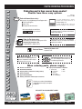
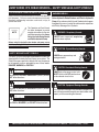
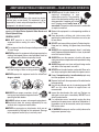
OPERATION AND PARTS MANUAL
JIMMY SERIES
MODELS:
JB5135, JB7135, JB5090, JB7090,
JB8090, JB9180, JB11090
HYDRAULIC REBAR BENDERS
MODEL JPU1
ELECTRIC-HYDRAULIC PUMP
Revision #9 (01/04/08)
To find the latest revision of this
publication, visit our website at:
www.multiquip.com
THIS MANUAL MUST ACCOMPANY THE EQUIPMENT AT ALL TIMES.
JIMMY SERIES HYDRAULIC REBAR BENDERS — SILICOSIS WARNING
WARNING
WARNING
SILICOSIS WARNING
RESPIRATORY HAZARDS
Grinding/cutting/drilling of masonry, concrete, metal and
other materials with silica in their composition may give
off dust or mists containing crystalline silica. Silica is a
basic component of sand, quartz, brick clay, granite and
numerous other minerals and rocks. Repeated and/or
substantial inhalation of airborne crystalline silica can
cause serious or fatal respiratory diseases, including
silicosis. In addition, California and some other
authorities have listed respirable crystalline silica as a
substance known to cause cancer. When cutting such
materials, always follow the respiratory precautions
mentioned above.
Grinding/cutting/drilling of masonry, concrete, metal and
other materials can generate dust, mists and fumes
containing chemicals known to cause serious or fatal
injury or illness, such as respiratory disease, cancer,
birth defects or other reproductive harm. If you are
unfamiliar with the risks associated with the particular
process and/or material being cut or the composition of
the tool being used, review the material safety data
sheet and/or consult your employer, the material
manufacturer/supplier, governmental agencies such as
OSHA and NIOSH and other sources on hazardous
materials. California and some other authorities, for
instance, have published lists of substances known to
cause cancer, reproductive toxicity, or other harmful
effects.
Control dust, mist and fumes at the source where
possible. In this regard use good work practices and
follow the recommendations of the manufacturers or
suppliers, OSHA/NIOSH, and occupational and trade
associations. Water should be used for dust
suppression when wet cutting is feasible. When the
hazards from inhalation of dust, mists and fumes cannot
be eliminated, the operator and any bystanders should
always wear a respirator approved by NIOSH/MSHA for
the materials being used.
JIMMY SERIES HYDRAULIC REBAR BENDERS — OPERATION AND PARTS MANUAL — REV. #9 (01/04/08) — PAGE 2
JIMMY SERIES HYDRAULIC REBAR BENDERS — TABLE OF CONTENTS
Multiquip Jimmy Series
Hydraulic Rebar Benders
NOTE
Silicosis Warning ....................................................... 2
Table Of Contents ..................................................... 3
Parts Ordering Procedures ....................................... 4
Safety Message Alert Symbols ................................. 5
Rules For Safe Operation ...................................... 6-8
Specifications (Rebar Unit) ....................................... 9
Specifications (Pump) ............................................. 10
General Information ........................................... 11-12
Components............................................................ 13
Inspection ................................................................ 14
Applying Power ....................................................... 15
Operation ........................................................... 16-19
Shut-Down .............................................................. 19
Maintenance ........................................................... 20
Explanation Of Code In Remarks Column .............. 22
Suggested Spare Parts ........................................... 23
Nameplate and Decals....................................... 24-25
JB5135 Assembly ............................................. 26-27
JB7135 Assembly ............................................. 28-29
JB5090 Assembly ............................................. 30-31
JB7090 Assembly ............................................. 32-33
JB8090 Assembly ............................................. 34-35
JB9180 Assembly ............................................. 36-37
JB11090 Assembly ........................................... 38-39
Electric Pump Assembly..................................... 40-41
Control Valve Assembly...................................... 42-43
NOTE
As a continuing effort to
update our parts book,
contact the MULTIQUIP
literature department for the
latest revision of your
"Operation and Parts
Manual"
Specification and part number
are subject to change without
notice.
Terms and Conditions of Sale ................................. 44
JIMMY SERIES HYDRAULIC REBAR BENDERS — OPERATION AND PARTS MANUAL — REV. #9 (01/04/08) — PAGE 3
www.multiquip.com
PARTS ORDERING PROCEDURES
Ordering parts has never been easier!
Choose from three easy options:
Effective:
January 1st, 2006
Best Deal!
Order via Internet (Dealers Only):
If you have an MQ Account, to obtain a
Username and Password, E-mail us at:
[email protected].
Order parts on-line using Multiquip’s SmartEquip website!
■ View Parts Diagrams
■ Order Parts
■ Print Specification Information
To obtain an MQ Account, contact your
District Sales Manager for more information.
Use the internet and qualify for a 5% Discount
on Standard orders for all orders which include
complete part numbers.*
Goto www.multiquip.com and click on
Order Parts to log in and save!
Note: Discounts Are Subject To Change
Order via Fax (Dealers Only):
Fax your order in and qualify for a 2% Discount
on Standard orders for all orders which include
complete part numbers.*
All customers are welcome to order parts via Fax.
Domestic (US) Customers dial:
1-800-6-PARTS-7 (800-672-7877)
Note: Discounts Are Subject To Change
Order via Phone: Domestic (US) Dealers Call:
1-800-427-1244
Non-Dealer Customers:
Contact your local Multiquip Dealer for
parts or call 800-427-1244 for help in
locating a dealer near you.
International Customers should contact
their local Multiquip Representatives for
Parts Ordering information.
When ordering parts, please supply:
❒
❒
❒
❒
❒
❒
Dealer Account Number
Dealer Name and Address
Shipping Address (if different than billing address)
Return Fax Number
Applicable Model Number
Quantity, Part Number and Description of Each Part
❒
Specify Preferred Method of Shipment:
✓ UPS/Fed Ex
✓ DHL
■ Priority One
✓ Truck
■ Ground
■ Next Day
■ Second/Third Day
All orders are treated as Standard Orders
and will ship the same day if received prior
to 3PM PST.
WE ACCEPT ALL MAJOR CREDIT CARDS!
JIMMY SERIES HYDRAULIC REBAR BENDERS — OPERATION AND PARTS MANUAL — REV. #9 (01/04/08) — PAGE 4
JIMMY SERIES HYD. REBAR BENDERS— SAFETY MESSAGE ALERT SYMBOLS
FOR YOUR SAFETY AND THE SAFETY OF OTHERS!
Safety precautions should be followed at all times when operating
this equipment. Failure to read and understand the Safety
Messages and Operating Instructions could result in injury to
yourself and others.
NOTE
This Operation and Parts Manual
has been developed to provide
complete instructions for the safe
and efficient operation of the Jimmy
Series Hydraulic Rebar Bender
and Electric-Hydraulic Pump.
HAZARD SYMBOLS
Potential hazards associated with the operation of the Jimmy
Series Hydraulic Rebar Benders and Electric Hydraulic
Pump will be referenced with Hazard Symbols which appear
throughout this manual, and will be referenced in conjunction
with Safety Message Alert Symbols.
WARNING - Respiratory Hazards
ALWAYS wear approved respiratory
protection when required.
Before using this hydraulic rebar bender and pump, ensure
that the operating individual has read and understands all
instructions in this manual.
CAUTION - Eye and Hearing Hazards
SAFETY MESSAGE ALERT SYMBOLS
The three (3) Safety Messages shown below will inform you
about potential hazards that could injure you or others. The
Safety Messages specifically address the level of exposure
to the operator, and are preceded by one of three words:
DANGER, WARNING, or CAUTION.
DANGER
You WILL be KILLED or SERIOUSLY injured if you DO
NOT follow directions.
WARNING
You CAN be KILLED or SERIOUSLY injured if you DO
NOT follow directions.
CAUTION
ALWAYS wear approved eye and
hearing protection.
CAUTION - Accidental Starting Hazards
ALWAYS place the power control unit's
ON/OFF switch in the OFF position when
the rebar bender is not in use.
CAUTION - Equipment Damage Hazards
Other important messages are provided throughout this
manual to help prevent damage to your rebar bender, other
property, or the surrounding environment.
CAUTION
You CAN be INJURED if you DO NOT follow directions.
JIMMY SERIES HYDRAULIC REBAR BENDERS — OPERATION AND PARTS MANUAL — REV. #9 (01/04/08) — PAGE 5
JIMMY SERIES HYDRAULIC REBAR BENDERS — RULES FOR SAFE OPERATION
DANGER
Read this manual!
Failure to follow instructions in this manual may lead to
serious injury or even death! This equipment is to be
operated by trained and qualified personnel only! This
equipment is for industrial use only.
The following safety guidelines should always be used when
operating the Jimmy Series Hydraulic Rebar Bender and
Electric-Hydraulic Pump.
GENERAL SAFETY
■ DO NOT operate or service this
equipment before reading this entire
manual.
■ This equipment should not be operated by persons under
18 years of age.
■ NEVER operate this equipment without proper protective
clothing, shatterproof glasses, steel-toed boots, hard hat
and other protective devices required by the job.
■ NEVER operate this equipment when not feeling
well due to fatigue, illness or taking medicine.
■ NEVER operate this equipment under the influence of
drugs or alcohol.
■ ALWAYS wear proper respiratory (mask),
hearing and eye protection equipment when
operating the rebar bender.
■ ALWAYS replace any worn or damaged warning decals.
■ Manufacturer does not assume responsibility for any
accident due to equipment modifications.
■ NEVER use accessories or attachments, which are not
recommended by Multiquip for this equipment. Damage
to the equipment and/or injury to user may result.
■ NEVER operate the rebar bender in an
explosive atmosphere or near
combustible materials. The possibility
exists of the rebar bender emitting a spark
during operation. A explosion or fire could
result causing severe bodily harm or
even death if the sparks make contact with combustible
or explosive materials.
■ Maintain this equipment in a safe operating condition at
all times.
■ Keep bystanders, children and visitors away while
operating the rebar bender. Distractions can cause you
to lose control.
■ DO NOT wear loose clothing or jewelry. Contain long hair.
Keep your hair, clothing, and gloves away from moving
parts.
■ ALWAYS store equipment properly when it is not being
used. Equipment should be stored in a clean, dry location
out of the reach of children.
■ ALWAYS be sure the operator is familiar with proper
safety precautions and operation techniques before using
rebar bender.
■ ALWAYS keep work area clean and free of foreign matter
and debris. Also keep work area well lit.
■ NEVER leave the rebar bender unattended. When not in
use always unplug the rebar bender from power source.
■ Keep all inexperienced and unauthorized people away
from the equipment at all times.
■ Become familiar with the components of the rebar bender
before operating.
■ Use this rebar bender only for its intended purpose. DO
NOT use this rebar bender for applications not
recommended.
■ Inspect the rebar bender after each use. Replace any
damaged or worn parts immediately. DO NOT use a
defective rebar bender.
■ If a malfunction occurs, immediately unplug the rebar
bender from the power source and correct the problem. If
the problem can not be corrected, contact your nearest
MQ service center.
■ All WARNING statements must be carefully observed to
help prevent personal injury.
JIMMY SERIES HYDRAULIC REBAR BENDERS — OPERATION AND PARTS MANUAL — REV. #9 (01/04/08) — PAGE 6
JIMMY SERIES HYDRAULIC REBAR BENDERS — RULES FOR SAFE OPERATION
UNIT SAFETY INSTRUCTIONS
■ All hose connections must be tightened with the proper
tools before operating hydraulic power unit. DO NOT over
tighten. Connections should only be tightened securely
and leak-free. Over tightening can cause premature thread
failure or high-pressure fittings to split at pressures lower
than their rated capacities.
■ Should a hydraulic hose ever rupture, burst, or need to
be disconnected, immediately shut off the pump and
release all pressure. NEVER attempt to grasp a leaking
pressurized hose with your hands. The force of escaping
hydraulic fluid could cause serious injury.
■ NEVER subject the hose to potential hazard such as
fire, sharp surfaces, extreme heat or cold, or heavy
impact. DO NOT allow the hose to kink, twist curl, crush,
cut, or bend so tightly that the fluid flow within the hose
is blocked or reduced. Periodically inspect the hose for
wear, because any of these conditions can damage the
hose and possibly result in personal injury.
■ NEVER use the hose to move attached equipment. Stress
can damage the hose and possibly cause personal injury.
■ Hose material and coupler seals must be compatible with
the hydraulic fluid used. Hoses also must not come in
contact with corrosive materials such as creosoteimpregnated objects and some paints. Hose deterioration
due to corrosive materials can result in personal injury.
Consult the manufacturer before painting a hose. NEVER
paint a coupler.
■ Use only approved accessories and approved hydraulic
fluid. Hoses, seals and all components used in a system
must be compatible with the hydraulic fluid used.
■ DO NOT exceed the rated capacities of the cylinders.
Excess pressure can result in personal injury.
■ Inspect each cylinder and coupler before each shift or
usage to prevent unsafe conditions from developing.
■ DO NOT use cylinders if they are damaged, altered or in
poor condition.
■ DO NOT use cylinders with bent or damaged couplers or
damaged port threads.
DANGER - High Pressure Hazard
When extending a cylinder or ram
under load, always insure that the
couplers or port threads have not
been damaged or do not come in
contact with any rigid obstruction.
If this condition does occur, the
coupler’s attaching threads may
become stripped or pulled from the cylinder or ram
resulting in the instantaneous release of high pressure
hydraulic fluid, flying objects, and loss of the load. All of
these possible results could cause serious injury or even
death.
CAUTION - System Evaluation
Cylinder hoses, couplings and hydraulic pump must all be
rated for the same operating pressure, correctly connected
and compatible with the hydraulic fluid used. An improperly
matched system could cause the system to fail and
possibly cause serious injury. Always maintain the correct
operating for optimal performance. If you have any
questions, please contact your nearest MQ service center.
■ Avoid pinch points or crush points that can be created
by the load or parts of the cylinder. Do not wear loose
jewelry when operating the rebar bender.
WARNING
Moving parts can
crush and cut.
ALWAYS keep hands
clear of rollers while
rebar bender is
operating.
■ NEVER use extreme heat to disassemble a hydraulic
cylinder or ram. Metal fatigue and/or seal damage will
result and can lead to unsafe operating conditions.
JIMMY SERIES HYDRAULIC REBAR BENDERS — OPERATION AND PARTS MANUAL — REV. #9 (01/04/08) — PAGE 7
JIMMY SERIES HYDRAULIC REBAR BENDERS — RULES FOR SAFE OPERATION
ELECTRICAL SAFETY
■ ALWAYS test the ON/OFF switch on the hydraulic power
unit before operating. The purpose of this switch is to shut
down the rebar bender.
■ NEVER use a extension cord that is frayed or damaged
where the insulation has been cut.
■ NEVER carry the hydraulic power unit by its power cord
or disconnect it by yanking the cord from the power outlet.
■ ALWAYS make certain that the proper extension cord
has been selected for the job. See Table 5.
■ NEVER allow power cord to lay in water.
■ NEVER stand in water while operating the rebar bender.
■ When connecting the hydraulic power unit to a power
receptacle, make sure the receptacle circuit is connected
to either a GFCI receptacle or a receptacle protected by
a 20 amp circuit breaker.
■ When plugging the hydraulic power unit into a power
receptacle, check the nameplate for the correct operating
voltage. Operating the rebar bender at the wrong voltage
will damage the electrical components. ALWAYS read
the nameplate before applying power.
■ This hydraulic power unit is equipped with a 3-prong male
power plug. DO NOT use a 2-prong adapter when plugging
into a wall outlet. This will defeat the purpose of the ground
circuit. If the plug does not fit into the receptacle, contact
a qualified electrician to install a 3-conductor wall
receptacle (outlet).
■ Avoid body contact with grounded surfaces such as pipes,
radiators, ranges and refrigerators. There is an increased
risk of electrical shock if your body is grounded.
■ DO NOT expose the hydraulic power unit to rain or wet
conditions. Water entering the power unit will increase
the risk of electrical shock.
■ When operating the hydraulic power unit outside, be sure
to use the appropriate outdoor extension cord. This type
of extension cord reduces the risk of electrical shock.
■ ALWAYS remove the AC power cord from the power
source before performing any service or maintenance on
the rebar bender. This preventative safety measure
reduces the possibility of accidental starting.
POWER UNIT TRANSPORTING (Electric-Hydraulic Pump)
■ When transporting of the power unit (pump) is required,
ALWAYS carry unit by its handle.
■ ALWAYS wrap power and remote cable cords neatly to
avoid tripping and damage when transporting.
MAINTENANCE
■ NEVER lubricate components or attempt service on a
operational rebar bender.
■ ALWAYS maintain rebar bender in correct operating
condition.
■ ALWAYS fix damage to the rebar bender immediately
and always replace broken parts. Replace with only MQ
recommended parts.
EMERGENCIES
■ ALWAYS know the location of the nearest fire
extinguisher and first aid kit.
■ In emergencies always know the location of the
nearest phone or keep a phone on the job site.
Also know the phone numbers of the nearest
ambulance, doctor and fire department. This
information will be invaluable in the case of an
emergency.
JIMMY SERIES HYDRAULIC REBAR BENDERS — OPERATION AND PARTS MANUAL — REV. #9 (01/04/08) — PAGE 8
JIMMY SERIES HYDRAULIC REBAR BENDERS — SPECIFICATIONS (REBAR UNIT)
Table 1. Rebar Bender Specifications
Model
JB5135
J B7 1 3 5
J B5 0 9 0
JB7090
JB8090
J B9 1 8 0
JB11090
Bending Angle
135°
135°
90°
90°
90 °
180°
90°
#4, #5
#6, #7
#4, #5, #6
#6, #7, #8
#6, #7, #8, #9
#7, #8, #9, #10
#8, #9, #10, #11
5 (12.7)
5 (12.7)
5 (12.7)
8 (20.3)
8 (20.3)
11 (27.9)
14 (35.6)
2
2
3
3
3
3. 5
3.5
#5; 135°
#7; 135°
#5; 90°
#7; 90°
#8; 90°
#9; 180°
#11; 90°
110 (50)
Rebar Capacity
(Bar Size)
Minimum Bend
in. (cm) *
Minimum Bar Spacing inches on
center
ACI-Approved Bar Number; Bend
Radius**
Weight lb. (kg)
22 (10)
26 (12)
26 (12)
58 (26)
62 (29)
100 (45)
Shipping Weight lb. (kg)
34 (15)
47 (21)
39 (18)
74 (33)
89 (40)
119 (54)
136 (62)
Shipping Dimensions in. (cm)
23 x 11 x 3.5
(58.4x27.9x8.9)
30 x 13 x 24
(76x33x61)
19 x 9 x 3
(48.3x22.9x7.6)
30 x 13 x 24
(76x33x61)
17 x 9 x 4.5
(43.2x22.9x11.4)
30 x 13 x 24
(76x33x61)
21.5 x 12.5 x 5.5
(54.6x31.8x14)
24 x 13 x 15
(61x33x38)
27 x 14 x 5.5
(68.6x35.6x14)
24 x 13 x 15
(61x33x38)
19 x 17 x 6
(48.3x43.2x15.2)
24 x 13 x 15
(61x33x38)
27 x 19 x 6
(68.6x48.3x15.2)
24 x 13 x 15
(61x33x38)
90° Standard Bend
✓
✓
✓
✓
✓
✓
✓
Offset Bends
✓
✓
✓
✓
✓
✓
✓
Straightening
✓
✓
✓
✓
✓
✓
✓
Seismic Stirrup and Tie Hook
✓
✓
Overall Dimensions in. (cm)
Applications
✓
180° Cane Hook
* Minimum bend measured from bottom of machine to top of angle.
** American Concrete Institute (ACI) has approved the wheel used in this device as the proper radius for bending the bar size indicated; Concrete Reinforcing Steel
Institute(CRSI) requirements are met for the bar size indicated.
Table 2. Rebar Size Chart
Model
J B5 1 3 5
JB7135
J B5 0 9 0
JB7090
JB8090
JB9180
JB11090
Bending Radius
135°
135°
90°
90°
90°
180°
180°
#4 (10M/#13)
★★
★★
#5 (15M/#16)
★★★
★★★
★★
#6 (20M/#19)
★★
★
★★
★★
★★
★★
#7 (NA/#22)
★★★
★
★★★
★★
★★
★★
#8 (25M/#25)
★
★★★
★★★
★★
#9 (30M/#29)
★
★
★
★★
#10 (NA/#32)
★★
#11 (35M/#36)
★★★
NOTE
Rebar Size:
Standard 1/8 inch increments
(Metric Hard/Soft
Conversion)
Example:
#8 Rebar ÷ 8 = 1-inch
#4 Rebar ÷ 8 = 4/8 = 1/2-inch
★★★ ACI/CRSI Approved for this size
★★ Acceptable bend radius for ACI/CRSI requirements
★ Capable of bending rebar but does not meet ACICRSI requirements
Not capable of bending this size rebar
JIMMY SERIES HYDRAULIC REBAR BENDERS — OPERATION AND PARTS MANUAL — REV. #9 (01/04/08) — PAGE 9
JIMMY SERIES HYDRAULIC REBAR BENDERS — SPECIFICATIONS (PUMP)
Table 3. Electric Hydraulic Pump Specifications
Model
Motor Specification
PEW1501T
Type
Electric Pump
Motor
1.5 HP (1.11 kw)
Speed
1725 RPM
Input Voltage
Current
Pump
JPU1
115 @ 60 Hz
16.2 Amps
Sound Level
80 dBA
Oil Capacity
1 gal (3.78 lliters)
Pressure Rating
First Stage Pressure
10,000 psi (68,951 kPa)
700 psi (4,826 kPa)
Flow Rate @ No Load
415 in3 /min (6,800 cm3 /min)
Flow Rate @ 10,000 psi
61 in3 /min (1,000 cm3 /min)
Remote Control Cable
Control Valve
15 ft. (4.57 meters)
Manual 3-Way 3-Position
Net Weight
79.2 lbs. (32.7 kg.)
Gross Weight
104 lbs. (47.1 kg.)
Carton Dimension (L x W x H)
16-5/8 x 11-1/8 x 21-1/8 in.
(42.22 x 28.25 x 53.65 cm.)
Crate Dimension (L x W x H)
17-1/2 x 11-5/8 x 22-7/8 in.
(44.45 x 29.52 x 58.10 cm.)
JIMMY SERIES HYDRAULIC REBAR BENDERS — OPERATION AND PARTS MANUAL — REV. #9 (01/04/08) — PAGE 10
JIMMY SERIES HYDRAULIC REBAR BENDERS — GENERAL INFORMATION
GENERAL INFORMATION
Rebar Straightening
The MQ Jimmy Series Hydraulic Rebar Benders are designed
to be used as portable on-site rebar benders, capable of bending
in-place rebar to approved American Concrete Institute (ACI) radius.
Labor time and injuries are greatly reduced from manually bending
rebar. Bends of 90°, 135° or 180° can now be completed in seconds
at the correct elevation after forms are stripped away.
■ Rebar can be straightened using JB5090, JB7090, JB8090,
JB9180 and JB11090.
■ NEVER straighten rebar that is bent greater than 30°. Check
with building codes before straightening rebar
With seven models to choose from, the Jimmy Series rebar benders
can accommodate a wide variety of rebar angles and sizes. Please
reference Tables 1 and 2 in this manual for the rebar bender that
best fits your application.
REBAR BENDING APPLICATIONS (Figures 1 thru 4)
■
■
■
■
■
■
■
Pilings
Caissons
Bridge and Decking
Retrofits
Columns
Straightening
Walls
Rebar Columns
■ 90° rebar (Figure 1) at top of column can be bent after forms
have been removed
■ Bending after concrete is poured allows you to stock bottom
beam bars, eliminating the need to thread bottom beam bars.
■ Rebar at top of column can be bent at exactly the correct
elevation allowing top beam bars to placed on top of 90°
bend.
Figure 2. Rebar Straightening
■ Before the rebar can be straightened by the JB5090, JB7090
or JB8090, it will be necessary to replace the main roller with
the straightening roller. The straightening roller is included
with each of the above models from the factory. To accomplish
this task remove the main shaft as outlined in Figure 14.
CAUTION
CAUTION
Some agencies may not permit the straightening of rebar
for existing bends of more than 30°. DO NOT attempt to
straighten rebar bends greater than 30°.
Figure 1. Columns
JIMMY SERIES HYDRAULIC REBAR BENDERS — OPERATION AND PARTS MANUAL — REV. #9 (01/04/08) — PAGE 11
JIMMY SERIES HYDRAULIC REBAR BENDERS — GENERAL INFORMATION
Rebar Spirals and Cages
Electric-Hydraulic Pump
■ Can bend rebar up to 135° (Figure 3) and fits between spirals
as close as 2 in. (5 cm. ) on center.
■ No welding required.
All Jimmy Series Hydraulic Rebar Benders require an electricpowered hydraulic pump to supply the necessary pressure to actuate
the hydraulic cylinder. This hydraulic pump consists of a drive
cylinder, oil reservoir and electronics for either remote or manual
operation.
The electric motor for this pump is a 1.5 HP motor. Each electric
motor requires 115 VAC, 60 Hz input for normal operation. Amperage
draw for the electric motor at 10,0000 psi (68,951 kpa) is
approximately 13 amps. Reference Figure 5 for oil volume versus
pressure.
The hydraulic pump is equipped with a 3-way, 3- position manual
operated valve. This valve allows the operator to remotely control
the advance, hold and return functions of the rebar bender. A 15 ft.
(4.57 meters) remote control cable allows the operator to control the
pump remotely.
450
Figure 3. Rebar Spirals and Cages
Rebar Walls
■
■
■
■
No welding required
Bends hooks in rebar after forms have been removed.
Bends graduated bars to precise elevations.
Reduces size and number of holes and splices required in
forms.
Oil Volume (cu.in/min)
400
350
300
250
200
150
100
50
0
0
1000
2000
3000
4000
5000
6000
7000
8000
9000 10000
P re s s ure (ps i)
Figure 5. Oil Volume vs Pressure
Model PEW1501T Electric/Hydraulic Pump
Figure 4. Rebar Walls
JIMMY SERIES HYDRAULIC REBAR BENDERS — OPERATION AND PARTS MANUAL — REV. #9 (01/04/08) — PAGE 12
JIMMY SERIES HYDRAULIC REBAR BENDERS — COMPONENTS
Figure 6. Jimmy Hydraulic Rebar Bender Components
1.
2.
3.
4.
5.
6.
7.
8.
9.
Remote Control Unit – Allows the hydraulic cylinder
on the rebar unit to be advanced or held.
Remote Control Cable – Allows the Electric-Hydraulic
Pump to be operated remotely.
Hydraulic Reservoir– Holds 1.00 gallon (3.78 liters)
of hydraulic oil. Fill only with recommended type
hydraulic oil.
Pump Control Lever – Move this lever to actuate the
hydraulic cylinder on the rebar bender. The lever allows
the cylinder to be advanced, held or returned.
Hydraulic Oil Fill Cap – Remove this cap to add
hydraulic fluid to the reservoir. Fill with commercial
hydraulic oil.
Electric-Hydraulic Pump/Carrying Handle – When
transporting of the pump is required, always use the
carrying handle or lifting bale to lift the unit.
Electric-Hydraulic Pump ON/OFF Switch – Move the
toggle switch to the forward position to activate the
electric motor. The electric motor will stay on as long
as the switch is held. Release the switch to turn off the
electric motor.
AC Power Cord – Plug this 10 ft. (3.0 meters) power
cord into a 115 VAC grounded type receptacle. NEVER
remove the ground pin from the plug. This will defeat
the ground circuit and greatly increase the possibility
of electrical shock.
Female Quick Disconnect Fitting – Connects to the
hydraulic hose and allows for easy removal.
10. Hydraulic Hose (Rebar Bender) – Connect one end
of this hose to the female quick disconnect fitting on
the electric-hydraulic pump, connect the other end (90°
fitting) to the hydraulic input port on the rebar bender
cylinder.
11. Hose Cap – When the rebar bender is not in use,
ALWAYS cover the hose’s male fitting with this cap.
This will prevent dirt and foreign matter from entering
the cylinder cavity.
12. Main and Upper Arm Rollers – Always keep large
and small rollers clean and lubricated to insure smooth
rolling. Remove any dirt or debris that may have
accumulated on the rollers during operation.
13. Hydraulic Cylinder – When actuated can apply a force
between 2~10 tons (2,032 ~10,160 kg.)
14. Rebar Adjustment Bolt – There is an adjustment bolt
on the side plate of the rebar bender. Adjust these bolts
to accommodate different size rebar.
15. Main Roller Shaft – To remove the large roller (main)
or stuck rebar from the unit, push the roller shaft inward
to release. Some units have a pin-clip mechanism for
the removal of the main roller. See Figure 14.
16. Electric Motor On/Off Switch – When placed in the
ON position, supplies 115VAC, 60Hz power to the
electric motor.
17. Straightening Roller – Accessory roller for
straightening rebar. For use with JB5090, JB7090,
JB8090 only.
JIMMY SERIES HYDRAULIC REBAR BENDERS — OPERATION AND PARTS MANUAL — REV. #9 (01/04/08) — PAGE 13
JIMMY SERIES HYDRAULIC REBAR BENDERS — INSPECTION
BEFORE STARTING
CAUTION - Read Manual
Before attempting to operate
this rebar bender, and to avoid
serious injury to personnel,
always read and understand
operation manual. Failure to
read and understand operation
manual could result in serious
harm or even death!
DANGER - Flammable/Combustible Materials
NEVER operate the rebar bender or
hydraulic pump in or around flammable
materials. The possibility exists of the rebar
bender emitting a spark during operation. If
contact is made between the sparks and the
flammable material, the result could be fire
or explosion causing damage to the equipment and severe
bodily harm even death!
INSPECTION
Before each use, visually inspect the items listed below.
Regular maintenance and visual checks of the rebar bender
and power unit prior to operation will minimize repairs and
help ensure normal operation of the bender and electrichydraulic pump.
■ Check for wear and damage to rollers, pin, nuts and bolts,
clip, side plates and hydraulic arm. Clean, lubricate and
replace as required.
■ Rebar bender can ONLY be used with a standard
hydraulic pump rated at 10,000 PSI. Refer to the pump’s
manual for operation and maintenance instructions.
■ Check the hydraulic pump fluid level.
■ Check that all hydraulic connections are clean.
■ Check all hydraulic hoses for cuts, holes, or excessive
wear.
■ Inspect all fittings and couplers, make sure they are clean
and fitted with dust caps.
■ Check that couplings to pump and bender are tightened
securely.
■ Check for a cracked or damaged cylinder or rebar bender
■ Check for excessive wear, bending, damage, or
insufficient thread engagement.
■ Check for leaking hydraulic fluid
■ Check for a scored or damaged piston rod.
■ Improperly functioning or damaged components
■ Check for loose bolts.
■ Check for damaged or improperly assembled accessory
equipment.
■ Check for modified, welded, or altered equipment.
■ Check for bent or damaged couplers or port threads.
JIMMY SERIES HYDRAULIC REBAR BENDERS — OPERATION AND PARTS MANUAL — REV. #9 (01/04/08) — PAGE 14
JIMMY SERIES HYDRAULIC REBAR BENDERS — APPLYING POWER
CONNECTING THE POWER
1. The electric-hydraulic pump requires 115 VAC, 60 Hz
power. Applying power to the pump that is not specified will cause severe damage to the pump's electric
motor. Always read the electrical data plate before
applying power to the pump.
2. The power plug on the pump is a 3-prong grounded type
plug. ALWAYS connect this plug to a 3-prong grounded
receptacle. NEVER plug this device into a 2-prong type
receptacle. This will defeat the ground circuit. The use of
a 3-prong to 2-prong adapter is strictly prohibited.
Since distance can affect voltage
drop when using an extension cord,
ALWAYS make certain that the
proper extension cord has been selected for the job. See Table 4.
NOTE
4. Connect the hand-held remote control cable to the power
input receptacle on the power unit
5. To apply power to the electric-hydraulic pump, place the
ON/OFF toggle switch (Figure 7) to the ON position (up).
3. Connect the pump's AC power cord to a 115 VAC wall
receptacle or portable generator (Figure 7) that is protected by a 20 amp circuit breaker. For best results
connect the power cord to a GFCI receptacle.
Figure 7. Connecting The Power
DANGER - ELECTROCUTION HAZARDS
Table 4. Cable Selection (60 Hz, Single Phase Operation)
During operation of this rebar bender, there
exists the possibility of electrocution,
electrical shock or burn, which can cause
severe bodily harm or even DEATH!
Current in
Amperes
To avoid these hazards:
NEVER use damaged or worn cables when plugging the
rebar bender into an AC power receptacle.
WET
HANDS
NEVER grab or touch a live power
cord with wet hands.
NEVER stand in water and touch a
live power cord.
POWER
CORD
(POWER ON)
Load In
Watts
Maximum Allowable Cable Length
At 120
Volts
#10 Wire
#12 Wire
#14 Wire
#16 Wire
2.5
300
1000 ft.
600 ft.
375 ft.
250 ft.
5
600
500 ft.
300 ft.
200 ft.
125 ft.
7.5
900
350 ft.
200 ft.
125 ft.
100 ft.
10
1200
250 ft.
150 ft.
100 ft.
15
1800
150 ft.
100 ft.
65 ft.
20
2400
125 ft.
75 ft.
50 ft.
CAUTION: Equipment damage can result from low voltage.
JIMMY SERIES HYDRAULIC REBAR BENDERS — OPERATION AND PARTS MANUAL — REV. #9 (01/04/08) — PAGE 15
JIMMY SERIES HYDRAULIC REBAR BENDERS — OPERATION
OPERATION
Remote Control Unit
Control Valve Lever
1. This hydraulic pump has a 3-way, 3-position valve that
is activated by a control valve lever (Figure 8). In the
neutral position, “PORT A” is CLOSED, meaning there
is no flow of pressurized fluid.
1. On the remote control unit there is a toggle switch.
When pressed, this toggle switch (Figure 11) will
activate (extend) the hydraulic cylinder. Releasing
the toggle switch will hold the cylinder in place.
Figure 8. Control Valve Lever (Neutral Position)
2. In the forward (extend) position, “PORT A” is OPEN,
meaning the flow of pressurized fluid is allowed (Figure
9) and the hydraulic cylinder will extend once the remote
control toggle switch is pressed.
Figure 11. Remote Control Unit
NOTE
Figure 9. Control Valve Lever (Forward Position)
3. In the reverse (retract) position, “PORT A” returns
hydraulic fluid back into tank (Figure 10) and the hydraulic cylinder retracts.
Figure 10. Control Valve Lever (Reverse Position)
NOTE
The cylinder on the JB5135 and
JB7135 models retract when the
control valve lever is in the forward
position and extend when the lever is
in the reverse position. See Figure 15.
The Remote Control Unit does not
retract the hydraulic cylinder. The
retraction of the cylinder must be
done manually (Power Unit).
Positioning the Rebar Bender (Method 1)
For Models JB5090, JB7090, JB8090, JB9180, JB11090
1. Place the pump control valve lever (Figure 8) in the
neutral position.
2. Place the rebar bender over the rebar between the main
roller and upper roller arm at the desired elevation of the
bend as shown in Figure 12. Use vise-grips to hold the
rebar bender base in place.
3. Rotate the rebar bender until the hydraulic cylinder is in
the opposite direction of the desired bend.
CAUTION
CAUTION
Make certain the area is clear of bystanders before starting
the bending process.
JIMMY SERIES HYDRAULIC REBAR BENDERS — OPERATION AND PARTS MANUAL — REV. #9 (01/04/08) — PAGE 16
JIMMY SERIES HYDRAULIC REBAR BENDERS — OPERATION
Figure 12. Rebar Placement
Figure 13. 90° Rebar Bend
4. Place the pump control valve lever in the forward
position (Figure 9).
5. Place and hold the toggle switch on the remote control
unit in the ON position.The rebar bending process should
begin.
6. When the desired rebar bend angle (Figure 13) has been
achieved, release the toggle switch on the remote
control unit. This will stop the forward motion of the
cylinder.
7. To retract the cylinder, place the pump control valve
lever in the reverse/retract position. The cylinder will
retract with or without the pump running.
Positioning the Rebar Bender (Method 2)
For Models JB5090, JB7090, JB8090, JB9180, JB11090
8. To remove the rebar bender, place the pump control
valve lever in the neutral position and either lift the
bender over the end of the rebar or remove the main roller
and shaft (Figure 14) and slide the rebar bender off the
rebar.
NOTE
The JB5090, JB7090 and JB8090
bender may require adjustment in
order to obtain a 90° bend. See
Rebar Adjustment Bolt section.
WARNING
Use ONLY graded rebar. Ungraded rebar may break and
cause serious injury!
1. Place the pump control valve lever (Figure 8) in the
neutral position.
2. Remove the Main Roller Shaft as shown in Figure 14.
Apply a suitable amount of pressure to the shaft to
either insert or remove it. It is held in place by a detent
ball plunger
Figure 14. Removing the Main Roller Shaft
3. Next, remove the main roller and place the rebar bender
over the rebar. Use vise-grips to hold the rebar bender
base in place.
3a. When bending rebar with models JB5090, JB7090,
JB8090 only: exchange the main roller for the straightening roller supplied from the factory.
4. Reinsert the main roller, making sure the rebar is positioned
between the main roller and the upper roller arm.
5. Operate rebar bender as outlined in Method 1, steps 3 thru 8.
JIMMY SERIES HYDRAULIC REBAR BENDERS — OPERATION AND PARTS MANUAL — REV. #9 (01/04/08) — PAGE 17
JIMMY SERIES HYDRAULIC REBAR BENDERS — OPERATION
Figure 15. JB5135 Rebar Placement — Rebar Bending
Figure 16. JB7135 Rebar Placement — Rebar Bending
Positioning the Rebar Bender (Method 3)
For Model JB5135
1. Place the pump control valve lever (Figure 8) in the
neutral position.
2. Send the end of the spiral rebar through the gap in the puller
hook. Secure the puller hook around the straight rebar and
align the puller rollers on the spiral rebar (Figure 15).
3. Place the pump control valve lever in the forward
position.
4. Place and hold the toggle switch on the remote control
unit (ON position). The rebar bending process should
begin.
Positioning the Rebar Bender (Method 4)
For Model JB7135
1. Place the pump control valve lever (Figure 8) in the
neutral position.
2. Send the end of the spiral rebar through the gap between
the puller hook and main roller. Rotate the main roller so
that the main roller groove is in the 1 o’clock position.
Secure the straight rebar in the main roller groove. Align
the puller rollers on the spiral rebar (Figure 16).
3. Operate rebar bender as outlined in Method 3, steps 3 thru 8.
5. Activating the rebar bender will then cause the puller
hook and cylinder to retract and curl the end of the spiral
rebar up to 135° around the straight rebar.
6. When the desired angle has been achieved, release the
toggle switch on the remote control unit. This will stop the
retraction of the puller hook and cylinder.
7. To extend the puller hook and cylinder, place the pump
control valve lever in the reverse/retract position.
8. To remove the rebar bender, place the pump control valve
lever in the neutral position and lift the bender over the
end of the rebar.
JIMMY SERIES HYDRAULIC REBAR BENDERS — OPERATION AND PARTS MANUAL — REV. #9 (01/04/08) — PAGE 18
JIMMY SERIES HYDRAULIC REBAR BENDERS — OPERATION/SHUT-DOWN
Rebar Adjustment Bolt
For Model JB5090, JB7090, JB8090
The rebar bender may require adjustment in order to obtain a
90° bend. Adjustment is necessary due to inconsistencies in the
rebar produced by steel mills and because each bender is
capable of handling multiple diameters of rebar.
1. Use a 19 MM socket to loosen the bolt and a 24 MM
socket to loosen the locknut (Figure 17) until the adjustable block can be slid easily in the crescent groove on
the side of the rebar. Note: there is no need to remove the
hardware.
2. Insert a piece of the rebar to be used into the machine
to assist in positioning the adjustable stop.
3. Slide the adjustable stop towards the rebar (away from
the hydraulic ram) until it makes contact with the rod.
4. Back the adjustable stop off the rebar slightly so the rod
can pass easily through the machine without binding.
5. Tighten the hardware securely , connect the bender to
the pump and make a test bend. You should now be able
to attain the desired bending angle. If the desired bend is
not attained, repeat the process until the desired result
is achieved.
Shutting Down the Rebar Bender and Power Unit
1. Remove Rebar Bender from the rebar.
2. Place ON/OFF toggle switch in the OFF position.
3. Unplug AC Power cord from receptacle.
4. Disconnect hydraulic hose from Power Unit.
5. Place protective hose cap on the male coupler end of
the hose.
6. Roll up hydraulic hose. Store Rebar Bender in a safe
place.
7. On the Power Unit, wrap the power and remote cords
neatly. Store Power Unit in safe place.
Figure 17. Rebar Adjustment Bolt
JIMMY SERIES HYDRAULIC REBAR BENDERS — OPERATION AND PARTS MANUAL — REV. #9 (01/04/08) — PAGE 19
JIMMY SERIES HYDRAULIC REBAR BENDERS — MAINTENANCE
PREVENTIVE MAINTENANCE
CHANGING HYDRAULIC OIL
Preventive maintenance should be performed on a daily or
weekly basis depending on the amount and working use. A
higher than normal operating pressure could indicate a need
for immediate maintenance.
A clean well lubricated rebar bender will operate faster and
smoother and will allow for more accurate readings from
pump pressure gauges.
1. Change hydraulic oil once a year.
2. Remove drain plug, tilt the pump, then pour used fluid
into a sealable container.
3. Dispose the hydraulic fluid in accordance with local
regulations.
4. Install drain cap.
PUMP MAINTENANCE (Cleaning and Lubrication)
1. Remove the side plates on the rebar bender to expose
moving parts. Clean all moving parts with a clean rag
and solvent.
2. Check the cylinder on all models for leaks.
5. Remove vent cap and fill with recommended type
hydraulic oil.
NOTE
3. Lubricate all moving parts with high pressure grease.
4. For rebar bender models with cables (Models JB11090
and JB9180), lubricate the five grease fittings daily or
after approximately 50 rebar bend operations. Check
hydraulic cables daily for fraying.
4. For rebar models JB135 and JB7135, visually check for
dents or cracks in the side plates. Replace plates
immediately if damaged. Clean and lubricate both rollers
to insure smooth rotation.
5. Check hydraulic oil every 40 hours of operation. Add
hydraulic oil if necessary. Oil can be added by removing
the vent cap. Use a funnel.
ADDING HYDRAULIC OIL
1. Make sure electric motor is OFF.
2. Depressurize system by placing pump control lever in
the neutral position. Disconnect hydraulic hose from
port A of system.
Completely change hydraulic oil
every 300 hours of operation.
Change the oil more frequently when
pump is used in an extremely dusty
environment or when the oil has
been overheated.
Use only good quality hydraulic oil.
Multiquip recommends Mobil DTE
NOTE
15M or equivalent. NEVER use
brake fluid, transmission fluid,
turbine oil, motor oil alcohol glycerin
etc. Use of other than the
recommended hydraulic oil will void warranty and damage the
pump and hydraulic hose used in the rebar bending application.
STORAGE
When the rebar bender and electric hydraulic pump are not
used, please store in a clean dry location out of the reach of
children and away from unauthorized personnel.
Be sure that all dust caps are attached to their respective
hoses and the hand-held remote control cable and pump
power cord are neatly wrapped.
3. Remove vent cap on top plate of reservoir. Visually
inspect to see if oil level is low. Oil level should be about
2 inches (50 mm) from top of reservoir plate.
4. Using a funnel, add oil to about 2 inches (50 mm) from
top of reservoir plate.
JIMMY SERIES HYDRAULIC REBAR BENDERS — OPERATION AND PARTS MANUAL — REV. #9 (01/04/08) — PAGE 20
NOTE PAGE
JIMMY SERIES HYDRAULIC REBAR BENDERS — OPERATION AND PARTS MANUAL — REV. #9 (01/04/08) — PAGE 21
JIMMY SERIES HYD.REBAR BENDERS — EXPLANATION OF CODE IN REMARKS
The following section explains the different symbols and
remarks used in the Parts section of this manual. Use the help
numbers found on the back page of the manual if there are any
questions.
The contents and part numbers listed in the parts section are
subject to change without notice. Multiquip does not
guarantee the availibility of the parts listed.
*
*
Numbers Used - Item quantity can be indicated by a
number, a blank entry, or A/R.
A/R (As Required) is generally used for hoses or other parts
that are sold in bulk and cut to length.
A blank entry generally indicates that the item is not sold
separately. Other entries will be clarified in the “Remarks”
Column.
REMARKS Column
Sample Parts List:
NO.
1
2
2
3
4
QTY. Column
PART NO. PART NAME
QTY. REMARKS
12345
BOLT ...................... 1 ......INCLUDES ITEMS W/
WASHER, 1/4 IN. ............. NOT SOLD SEPARATELY
12347
WASHER, 3/8 IN. ... 1 ......MQ-45T ONLY
12348
HOSE ................... A/R .... MAKE LOCALLY
12349
BEARING ............... 1 ......S/N 2345B AND ABOVE
*
NO. Column
Unique Symbols - All items with same unique symbol
( , #, +, %, or >) in the number column belong to the same
assembly or kit, which is indicated by a note in the “Remarks”
column.
*
Duplicate Item Numbers - Duplicate numbers indicate
multiple part numbers are in effect for the same general
item, such as different size saw blade guards in use or a
part that has been updated on newer versions of the same
machine.
When ordering a part that has more than one
item number listed, check the remarks column
for help in determining the proper part to order.
PART NO. Column
Numbers Used - Part numbers can be indicated by a
number, a blank entry, or TBD.
TBD (To Be Determined) is generally used to show a part
that has not been assigned a formal part number at time of
publication.
Some of the most common notes found in the “Remarks”
Column are listed below. Other additional notes needed to
describe the item can also be shown.
Assembly/Kit - All items on the parts list with the same
unique symbol will be included when this item is purchased.
Indicated by:
“INCLUDES ITEMS W/(unique symbol)”
Serial Number Break - Used to list an effective serial
number range where a particular part is used.
Indicated by:
“S/N XXXXX AND BELOW”
“S/N XXXX AND ABOVE”
“S/N XXXX TO S/N XXX”
Specific Model Number Use - Indicates that the part is
used only with the specific model number or model number
variant listed. It can also be used to show a part is NOT
used on a specific model or model number variant.
Indicated by:
“XXXXX ONLY”
“NOT USED ON XXXX”
“Make/Obtain Locally” - Indicates that the part can be
purchased at any hardware shop or made out of available
items. Examples include battery cables, shims, and certain
washers and nuts.
“Not Sold Separately” - Indicates that an item cannot be
purchased as a separate item and is either part of an
assembly/kit that can be purchased, or is not available for
sale through Multiquip.
A blank entry generally indicates that the item is not sold
separately or is not sold by Multiquip. Other entries will be
clarified in the “Remarks” Column.
JIMMY SERIES HYDRAULIC REBAR BENDERS — OPERATION AND PARTS MANUAL — REV. #9 (01/04/08) — PAGE 22
JIMMY SERIES HYD.REBAR BENDERS — SUGGESTED SPARE PARTS
JIMMY SERIES HYDRAULIC REBAR BENDER
1 to 3 Units (JB5135)
Qty. ..... P/N ...................... Description
1 ......... RB252698 ........... PULLER HOOK
1 ......... RB252818 ........... CAP SCREW, 5/8-18 X 2-1/2 LG
1 ......... RB252703 ........... ROLLER PIN
1 ......... RB252828 ........... BALL PLUNGER, 3/8-16
1 ......... RB252701 ........... WHEEL PULLER HOUSING
1 ......... RB252699 ........... PULLER ROLLER
2 ......... RB252852 ........... SET SCREW, 5/16 X 24 X 1/4
1 ......... RB9681 ............... STREET ELBOW FITTING
1 ......... CH38F ................ QUICK DISCONNECT COUPLER
1 ......... RB9777 ............... RUBBER HOSE, 10 FT
1 ......... RBHOSECAP ...... HOSE CAP
1 ......... CH38M ............... MALE HALF COUPLER, 3/8-18NPTF
JIMMY SERIES HYDRAULIC REBAR BENDER
1 to 3 Units (JB7135)
Qty. ..... P/N ...................... Description
1 ......... RB252710 ........... ROLLER PIN
1 ......... RB252828 ........... BALL PLUNGER, 3/8-16
1 ......... RB252707 ........... MAIN ROLLER
1 ......... RB252706 ........... PULLER HOOK
1 ......... RB10621 ............. 90 DEGREE FITTING, 3/8 NPTF
1 ......... CH38F ................ QUICK DISCONNECT COUPLER
1 ......... RB9777 ............... RUBBER HOSE, 10 FT
1 ......... RBHOSECAP ...... HOSE CAP
1 ......... CH38M ............... MALE HALF COUPLER, 3/8-18NPTF
JIMMY SERIES HYDRAULIC REBAR BENDER
1 to 3 Units (JB5090)
Qty. ..... P/N ...................... Description
1 ......... RB252671 ........... MAIN ROLLER SHAFT
1 ......... RB252828 ........... BALL PLUNGER, 3/8-16
1 ......... RB252665 ........... MAIN ROLLER
1 ......... RB9681 ............... STREET ELBOW FITTING
1 ......... CH38F ................ QUICK DISCONNECT COUPLER
1 ......... RB9777 ............... RUBBER HOSE, 10 FT
1 ......... RB HOSECAP ..... HOSE CAP
1 ......... RB001WHL ......... STRAIGHTENING WHEEL
1 ......... CH38M ............... MALE HALF COUPLER, 3/8-18NPTF
JIMMY SERIES HYDRAULIC REBAR BENDER
1 to 3 Units (JB7090)
Qty. ..... P/N ...................... Description
1 ......... RB252685 ........... MAIN ROLLER SHAFT
1 ......... RB252829 ........... BALL PLUNGER, 1/2-13
1 ......... RB252679 ........... MAIN ROLLER
1 ......... RB9681 ............... STREET ELBOW FITTING
1 ......... CH38F ................ QUICK DISCONNECT COUPLER
1 ......... RB9777 ............... RUBBER HOSE, 10 FT
1 ......... RBHOSECAP ...... HOSE CAP
1 ......... RB001WHL ......... STRAIGHTENING WHEEL
1 ......... CH38M ............... MALE HALF COUPLER, 3/8-18NPTF
JIMMY SERIES HYDRAULIC REBAR BENDER
1 to 3 Units (JB8090)
Qty. ..... P/N ...................... Description
1 ......... RB252685 ........... MAIN ROLLER SHAFT
1 ......... RB252829 ........... BALL PLUNGER, 1/2-13
1 ......... RB252694 ........... MAIN ROLLER
1 ......... RB9681 ............... STREET ELBOW FITTING
1 ......... CH38F ................ QUICK DISCONNECT COUPLER
1 ......... RB9777 ............... RUBBER HOSE, 10 FT
1 ......... RBHOSECAP ...... HOSE CAP
1 ......... RB001WHL ......... STRAIGHTENING WHEEL
1 ......... CH38M ............... MALE HALF COUPLER, 3/8-18NPTF
JIMMY SERIES HYDRAULIC REBAR BENDER
1 to 3 Units (JB9180)
Qty. ..... P/N ...................... Description
1 ......... RB252720 ........... MAIN WHEEL PIN
1 ......... RB252829 ........... BALL PLUNGER, 1/2-13
1 ......... RB252717 ........... FRONT PULLEY
1 ......... RB9681 ............... STREET ELBOW FITTING
1 ......... CH38F ................ QUICK DISCONNECT COUPLER
1 ......... RB9777 ............... RUBBER HOSE, 10 FT
1 ......... RBHOSECAP ...... HOSE CAP
1 ......... CH38M ............... MALE HALF COUPLER, 3/8-18NPTF
2 ......... RB252731 ........... CABLE, 44-1/2" LG.
JIMMY SERIES HYDRAULIC REBAR BENDER
1 to 3 Units (JB11090)
Qty. ..... P/N ...................... Description
1 ......... RB252720 ........... MAIN WHEEL PIN
1 ......... RB252829 ........... BALL PLUNGER, 1/2-13
1 ......... RB252717 ........... FRONT PULLEY
1 ......... RB9681 ............... STREET ELBOW FITTING
1 ......... CH38F ................ QUICK DISCONNECT COUPLER
1 ......... RB9777 ............... RUBBER HOSE, 10 FT
1 ......... RBHOSECAP ...... HOSE CAP
1 ......... CH38M ............... MALE HALF COUPLER, 3/8-18NPTF
1 ......... RB252738 ........... CABLE, 45-1/2" LG.
ELECTRIC-HYDRAULIC PUMP
1 to 3 Units (JPU1)
Qty. ..... P/N ...................... Description
1 ......... PEW01 ................ PENDANT SWITCH
1 ......... E0539940101 ...... REPAIR KIT FOR PISTON BLOCK
1 ......... E0539980105 ...... REPAIR KIT FOR MANIFOLD
1 ......... E0539960109 ...... REPAIR KIT FOR GEAR PUMP
1 ......... 64110100104 ...... SOCKET HEAD SCREW, M10X1.5X10
1 ......... E0561009101 ...... HANDLE, D10 X 98.5
1 ......... E0561008109 ...... KNOB, D30MM
1 ......... E0539910104 ...... BOLT KIT
1 ......... E0539911106 ...... REPAIR KIT
JIMMY SERIES HYDRAULIC REBAR BENDERS — OPERATION AND PARTS MANUAL — REV. #9 (01/04/08) — PAGE 23
JIMMY SERIES HYDRAULIC REBAR BENDERS — NAMEPLATE AND DECALS
NAMEPLATE AND DECALS
1
WARNING
Read, understand and follow any
and all printed materials provided
with and on this device. Do not
overload beyond rated capacity.
Never work under a load
supported by a hydraulic cylinder.
Immediately support liftef load
with suitable mechanical means.
Failure to heed these markings
may result in personal injury
and/ or property damage.
Engineered in U.S.A. Made in Taiwan
SFA Companies © 2003
MODEL
JBXXXX
BY MULTIQUIP
SERIAL NO. 59- 9 0 0 2
2
JIMMY SERIES HYDRAULIC REBAR BENDERS — OPERATION AND PARTS MANUAL — REV. #9 (01/04/08) — PAGE 24
JIMMY SERIES HYDRAULIC REBAR BENDERS — NAMEPLATE AND DECALS
NAMEPLATE AND DECALS
NO
1
2
2
2
2
2
2
2
PART NO
TBD
PART NAME
QTY.
REMARK
WARNING, READ MANUAL DECAL
1
NAMEPLATE, JB5135 ................................................. 1 ............ CONTACT MQ PARTS DEPT.
NAMEPLATE, JB7135 ................................................. 1 ............ CONTACT MQ PARTS DEPT.
NAMEPLATE, JB5090 ................................................. 1 ............ CONTACT MQ PARTS DEPT.
NAMEPLATE, JB7090 ................................................. 1 ............ CONTACT MQ PARTS DEPT.
NAMEPLATE, JB8090 ................................................. 1 ............ CONTACT MQ PARTS DEPT.
NAMEPLATE, JB9180 ................................................. 1 ............ CONTACT MQ PARTS DEPT.
NAMEPLATE, JB11090 ............................................... 1 ............ CONTACT MQ PARTS DEPT.
JIMMY SERIES HYDRAULIC REBAR BENDERS — OPERATION AND PARTS MANUAL — REV. #9 (01/04/08) — PAGE 25
JIMMY SERIES HYDRAULIC REBAR BENDERS — JB5135 ASSY.
JB5135 ASSY.
JIMMY SERIES HYDRAULIC REBAR BENDERS — OPERATION AND PARTS MANUAL — REV. #9 (01/04/08) — PAGE 26
JIMMY SERIES HYDRAULIC REBAR BENDERS — JB5135 ASSY.
JB5135 ASSY.
NO
1
2
3
4
5
6
7
8
9
10
11
12
13
14
15
16
17
18
19
20
21
PART NO
RB252698
RB252818
RB252839
RB252745
RB9681
CH38M
RB9777
HP0205PB
RB252702
RB252696
RB252697
RB252700
RB252703
RB252828
RB252701
RB252699
RB252852
PART NAME
QTY.
REMARK
PULLER HOOK
1
CAP SCREW(5/8- 18 X 2- 1/2LG.)
4
LOCK NUT(5/8- 18)
4
DECAL
1
STREET ELBOW FITTING (3/8 NPTF)
1
MALE HALF COUPLER (3/8-18NPTF)
1
RUBBER HOSE (10FT.)
1
CYLINDER (2 TON; 5IN. STROKE, ADAPTER INCLUDED) ........ 1 ............... REPLACES RP25PAC
HANDLE ASSY.
1
CYLINDER MOUNT
1
PULLER ARM (LEFT & RIGHT)
1
PULLER ROLLER
2
ROLLER PIN
1
BALL PLUNGER (3/8-16)
1
WHEEL PULLER HOUSING
1
PULLER ROLLER
1
SET SCREW (5/16- 24 X 1/4 LG. NYLON
LOCKING TIP INCLUDED)
2
RB253081
CAP SCREW (3/4- 16 X 2- 1/2 LG.: LONG SHANK)
2
RB252835
JAM NUT (3/4- 16)
2
RBHOSECAP HOSE CAP
1
CH38F
QUICK DISCONNECT COUPLER
1
JIMMY SERIES HYDRAULIC REBAR BENDERS — OPERATION AND PARTS MANUAL — REV. #9 (01/04/08) — PAGE 27
JIMMY SERIES HYDRAULIC REBAR BENDERS — JB7135 ASSY.
JB7135 ASSY.
JIMMY SERIES HYDRAULIC REBAR BENDERS — OPERATION AND PARTS MANUAL — REV. #9 (01/04/08) — PAGE 28
JIMMY SERIES HYDRAULIC REBAR BENDERS — JB7135 ASSY.
JB7135 ASSY.
NO
1
2
3
4
5
6
7
8
9
10
11
12
13
14
15
16
PART NO
RB252710
RB252828
RB252707
RB252706
RB252841
RB252820
RB252746
CH38M
RB10621
RB9777
HP0505PB
RB252709
RB252704
RB252705
RB252708
RB252852
17
18
19
20
RB253081
RB252835
RBHOSECAP
CH38F
PART NAME
QTY.
REMARK
ROLLER PIN
1
BALL PLUNGER
1
MAIN ROLLER
1
PULLER HOOK
1
LOCK NUT
4
CAP SCREW (3/4-16X 2-12)
4
DECAL
1
MALE HALF COUPLER (3/8-18NPTF)
1
90° ELBOW FITTING (3/8 NPTF)
1
RUBBER HOSE (10FT)
1
CYLINDER(5 TON; 5-1/2 IN. STROKE) ............................... 1 ........... REPLACES RP55PAC
HANDLE ASSEMBLY
1
CYLINDER MOUNT
1
PULLER ARM (LEFT & RIGHT)
4
PULLER ARM ROLLER
1
SET SCREW (5/16- 24 X 1/4 LG. NYLON
LOCKING TIP INCLUDED)
1
CAP SCREW (3/4- 16 X 2- 1/2 LG.: LONG SHANK)
2
JAM NUT (3/4- 16)
2
HOSE CAP
1
QUICK DISCONNECT COUPLER
1
JIMMY SERIES HYDRAULIC REBAR BENDERS — OPERATION AND PARTS MANUAL — REV. #9 (01/04/08) — PAGE 29
JIMMY SERIES HYDRAULIC REBAR BENDERS — JB5090 ASSY.
JB5090 ASSY.
JIMMY SERIES HYDRAULIC REBAR BENDERS — OPERATION AND PARTS MANUAL — REV. #9 (01/04/08) — PAGE 30
JIMMY SERIES HYDRAULIC REBAR BENDERS — JB5090 ASSY.
JB5090
NO.
1
2
3
4
5
6
7
8
9
10
11
12
13
14
15
16
17
18
19
20
21
22
23
24
25
26
27
28
ASSY.
PART NO.
RB252839
RB252844
RB252662
RB252672
RB9681
RB9777
H0509PB
RB252675
RB252852
RB252669
RB252667
RB252663
RB252815
RB252843
RB252674
RB252668
RB252665
RB252673
RB252664
RB252817
RB252671
RB252828
RB252831
RB252830
CH38M
RBHOSECAP
RB001WHL
CH38F
PART NAME
QTY.
REMARKS
LOCKNUT (5/8-18)
6
WASHER (5/8)
6
OUTSIDE PLATE (LEFT AND RIGHT)
1
CENTRAL SHAFT
1
STREET ELBOW FITTING (3/8 NPTF)
1
RUBBER HOSE (10')
1
CYLINDER (5 TON; 9-1/8" STROKE) ..................... 1 ................... REPLACES C59C-PAC
PLUNGER CLEVIS
1
SET SCREW (5/16-24 X 1/4 LG.)
1
CYLINDER TRUNION
1
UPPER ARM ROLLER
1
INSIDE SIDE PLATE RIGHT HAND
1
CAP SCREW (1/2-20 X 1-1/4 LG.)
1
WASHER (1/2")
1
STOP BOLT ASSEMBLY
1
ADJUSTABLE STOP
1
MAIN ROLLER
1
INSIDE PLATE SPACER
2
INSIDE SIDE PLATE LEFT HAND
1
CAP SCREW (8-5/8-18 X 2-1/2 LG.)
1
MAIN ROLLER SHAFT
1
BALL PLUNGER (3/8-16)
1
EXTERNAL LOCKWASHER (5/8")
1
EXTERNAL LOCKWASHER (1/2")
1
MALE HALF COUPLER (3/8-18NPTF)
1
HOSE CAP
1
STRAIGHTENING WHEEL
1
QUICK DISCONNECT COUPLER
1
JIMMY SERIES HYDRAULIC REBAR BENDERS — OPERATION AND PARTS MANUAL — REV. #9 (01/04/08) — PAGE 31
JIMMY SERIES HYDRAULIC REBAR BENDERS — JB7090 ASSY.
JB7090 ASSY.
JIMMY SERIES HYDRAULIC REBAR BENDERS — OPERATION AND PARTS MANUAL — REV. #9 (01/04/08) — PAGE 32
JIMMY SERIES HYDRAULIC REBAR BENDERS — JB7090 ASSY.
JB7090 ASSY.
NO.
1
2
3
4
5
6
7
8
9
10
11
12
13
14
15
16
17
18
19
20
21
22
23
24
25
26
27
28
29
30
31
32
33
PART NO.
RB252840
RB252845
RB252676
RB252686
RB9681
RB9777
H1012PB
RB252689
RB252852
RB252683
RB252681
RB252684
RB252678
RB252843
RB252815
RB252688
RBRB253046
RB252830
RBRB252682
RB252679
RB252687
RB252677
RB252821
RB252816
RB252685
RB252829
RB252838
RB252690
RB252854
CH38M
RBHOSECAP
RB001WHL
CH38F
PART NAME
QTY.
REMARKS
LOCKNUT (7/8-14)
5
WASHER (7/8)
5
OUTSIDE PLATE (LEFT AND RIGHT)
1
CENTRAL SHAFT
1
STREET ELBOW FITTING (3/8 NPTF)
1
RUBBER HOSE (10')
1
CYLINDER (10 TON; 12" STROKE) .......................... 1 ............ REPLACES C1012C-PAC
PLUNGER CLEVIS
1
SET SCREW (5/16-24 X 1/4 LG.)
1
CYLINDER TRUNION
1
UPPER ARM ROLLER
1
SPACER
1
INSIDE SIDE PLATE LEFT HAND
1
WASHER (1/2")
1
HEX CAP SCREW (1/2-20 X 1-1/4 LG.)
1
STOP BOLT WASHER
1
EXTERNAL LOCKWASHER (7/8")
1
EXTERNAL LOCKWASHER (1/2")
1
ADJUSTABLE STOP
1
MAIN ROLLER
1
INSIDE PLATE SPACER
1
INSIDE SIDE PLATE RIGHT HAND
1
HEX CAP SCREW (7/8-14 X 3-1/4 LG.)
1
HEX CAP SCREW (1/2-20 X 2-3/4 LG.)
1
MAIN ROLLER SHAFT
1
BALL PLUNGER (1/2-13)
1
LOCKNUT (1/2-20)
1
DOWEL PIN (7/8" DIA X 2")
1
GREASE FITTING (1/4-20)
5
MALE HALF COUPLER (3/8-18NPTF)
1
HOSE CAP
1
STRAIGHTENING WHEEL
1
QUICK DISCONNECT COUPLER
1
JIMMY SERIES HYDRAULIC REBAR BENDERS — OPERATION AND PARTS MANUAL — REV. #9 (01/04/08) — PAGE 33
JIMMY SERIES HYDRAULIC REBAR BENDERS — JB8090 ASSY.
JB8090 ASSY.
JIMMY SERIES HYDRAULIC REBAR BENDERS — OPERATION AND PARTS MANUAL — REV. #9 (01/04/08) — PAGE 34
JIMMY SERIES HYDRAULIC REBAR BENDERS — JB8090 ASSY.
JB8090 ASSY.
NO. PART NO.
1
RB252840
2
RB252845
3
RB252691
4
RB252686
5
RB9681
6
RB9777
7
H1014PB
8
RB252689
9
RB252852
10
RB252683
11
RB252681
12
RB252684
13
RB252693
14
RB252843
15
RB252815
16
RB252688
17
RB253046
18
RB252830
19
RB252682
20
RB252694
21
RB252687
22
RB252692
23
RB252821
24
RB252816
25
RB252685
26
RB252829
27
RB252838
28
RB252690
29
RB252047
30
CH38M
31
RBHOSECAP
32
RB001WHL
33
CH38F
PART NAME
QTY.
REMARKS
LOCKNUT (7/8-14)
5
WASHER (7/8)
5
OUTSIDE PLATE (LEFT AND RIGHT)
1
CENTRAL SHAFT
1
STREET ELBOW FITTING (3/8 NPTF)
1
RUBBER HOSE (10')
1
CYLINDER (10 TON; 14" STROKE) ......................... 1 ............ REPLACES C1014C-PAC
PLUNGER CLEVIS
1
SET SCREW (5/16-24 X 1/4 LG.)
1
CYLINDER TRUNION
1
UPPER ARM ROLLER
1
SPACER
1
INSIDE SIDE PLATE LEFT HAND
1
WASHER (1/2")
1
HEX CAP SCREW (1/2-20 X 1-1/4 LG.)
1
STOP BOLT WASHER
1
EXTERNAL LOCKWASHER (7/8")
1
EXTERNAL LOCKWASHER (1/2")
1
ADJUSTABLE STOP
1
MAIN ROLLER
1
INSIDE PLATE SPACER
1
INSIDE SIDE PLATE RIGHT HAND
1
HEX CAP SCREW (7/8-14 X 3-1/4 LG.)
1
HEX CAP SCREW (1/2-20 X 2-3/4 LG.)
1
MAIN ROLLER SHAFT
1
BALL PLUNGER (1/2-13)
1
LOCKNUT (1/2-20)
1
DOWEL PIN (7/8" DIA X 2")
1
GREASE FITTING (1/4-20)
5
MALE HALF COUPLER (3/8-18NPTF)
1
HOSE CAP
1
STRAIGHTENING WHEEL
1
QUICK DISCONNECT COUPLER
1
JIMMY SERIES HYDRAULIC REBAR BENDERS — OPERATION AND PARTS MANUAL — REV. #9 (01/04/08) — PAGE 35
JIMMY SERIES HYDRAULIC REBAR BENDERS — JB9180 ASSY.
JB9180 ASSY.
JIMMY SERIES HYDRAULIC REBAR BENDERS — OPERATION AND PARTS MANUAL — REV. #9 (01/04/08) — PAGE 36
JIMMY SERIES HYDRAULIC REBAR BENDERS — JB9180 ASSY.
JB9180 ASSY.
NO.
1
2
3
4
5
6
7
8
9
10
11
12
13
14
15
16
17
18
19
20
21
22
23
24
25
26
27
28
29
30
31
32
33
34
35
36
37
38
39
40
41
42
43
44
45
46
47
PART NO.
RB252716
RB252807
RB252711
RB252854
RB252741
RB252811
RB252713
RB252715
RB252719
RB252723
RB252742
RB252712
RB252725
RB252829
RB252720
RB253074
RB252840
RB252845
RB252717
RB252731
RB253067
RB252813
RB252842
RB252726
RB252824
RB252718
RB252721
RB252837
RB252814
RB252843
RB9681
RB9777
H1014PB
RB252714
RB252727
RB252728
RB252816
RB252821
RB252823
RB252722
RB252826
RB252833
RB252827
RB25200A
CH38M
RBHOSECAP
CH38F
PART NAME
QTY. REMARKS
TOP ROLLER
1
HEX CAP SCREW (1/4-20 X 1" LG.)
2
OUTSIDE SIDE PLATES (RIGHT AND LEFT)
2
GREASE FITTING (1/4-20)
5
COIL SPRING
2
HEX CAP SCREW (3/8-24 X 2-1/2" LG.)
1
INSIDE SIDE GUIDE PLATE (RIGHT AND LEFT)
2
HALF MAIN WHEEL (DOWEL PINS INCLUDED)
1
RAM SUPPORT AND CENTER SPACER (DOWEL PINS INCLUDED) 1
INSIDE MAIN PLATE PULLEY BUSHING (RIGHT AND LEFT)
2
SPACER
6
SIDE GUARD (RIGHT AND LEFT)
2
MAIN PULLEY BUSHING (RIGHT AND LEFT)
2
BALL PLUNGER (1/2-13)
1
MAIN WHEEL PIN
1
HEX CAP SCREW (5/16-24 X 1" LG.)
2
LOCKNUT (7/8-14)
4
WASHER (7/8")
6
FRONT PULLEY
2
CABLE (44-1/2" LG.)
2
HEX CAP SCREW (1/4-20 X 1-1/4 LG.)
6
HEX CAP SCREW (3/8-24 X 2-3/4 LG.)
3
WASHER (3/8”)
6
BAR STOP BUSHING
1
SOC. HD. CAP SCREW (5/16-18 X 3-1/2 LG.)
2
RAM PAD AND CENTER SUPPORT (DOWEL PIN INCLUDED)
1
FRONT PULLEY SHAFT
1
LOCKNUT (3/8-24)
3
HEX CAP SCREW (1/2-20 X 1" LG.)
1
WASHER (1/2")
2
STREET ELBOW FITTING (3/8 NPTF)
1
RUBBER HOSE (10')
1
CYLINDER (10 TON; 14" STROKE) ........................................................... 1 ....... REPLACES C1014C-PAC
RAM TOWER
1
CABLE GUIDE BLOCK
1
CABLE STOP BLOCK
1
HEX CAP SCREW (1/2-20 X 2-3/4 LG.)
1
HEX CAP SCREW (7/8-14 X 3-1/4 LG.)
1
HEX CAP SCREW (7/8-14 X 5" LG.)
1
TOP ROLLER PIN
1
FLAT HD. SOC. SCREW (1/4-28 X 3/4 LG.)
12
JAM NUT (3/8-24)
1
FLAT HD. SOC. SCREW (1/4-20 X 3/4 LG.)
12
SET SCREW (5/16-24 X 3/4 LG.)
1
MALE HALF COUPLER (3/8-18NPTF)
1
HOSE CAP
1
QUICK DISCONNECT COUPLER
1
JIMMY SERIES HYDRAULIC REBAR BENDERS — OPERATION AND PARTS MANUAL — REV. #9 (01/04/08) — PAGE 37
JIMMY SERIES HYDRAULIC REBAR BENDERS — JB11090 ASSY.
JB11090 ASSY.
JIMMY SERIES HYDRAULIC REBAR BENDERS — OPERATION AND PARTS MANUAL — REV. #9 (01/04/08) — PAGE 38
JIMMY SERIES HYDRAULIC REBAR BENDERS — JB11090 ASSY.
JB11090 ASSY.
NO.
1
2
3
4
5
6
7
8
9
10
11
12
13
14
15
16
17
18
19
20
21
22
23
24
25
26
27
28
29
30
31
32
33
34
35
36
37
38
39
40
41
42
43
44
45
46
47
PART NO.
RB252737
RB252807
RB252732
RB252854
RB252741
RB252811
RB252734
RB252736
RB252719
RB252723
RB252742
RB252729
RB252725
RB252829
RB252720
RB253074
RB252840
RB252845
RB252717
RB252738
RB253067
RB252813
RB252842
RB252726
RB252824
RB252718
RB252721
RB252837
RB252814
RB252843
RB9681
RB9777
H1010PB
RB252730
RB252727
RB252728
RB252816
RB252821
RB252823
RB252722
RB252826
RB252833
RB252827
RB25200A
CH38M
RBHOSECAP
CH38F
PART NAME
QTY. REMARKS
TOP ROLLER
1
HEX CAP SCREW (1/4-20 X 1" LG.)
2
OUTSIDE SIDE PLATES (RIGHT AND LEFT)
2
GREASE FITTING (1/4-20)
5
COIL SPRING
2
HEX CAP SCREW (3/8-24 X 2-1/2" LG.)
1
INSIDE SIDE GUIDE PLATE (RIGHT AND LEFT)
2
HALF MAIN WHEEL (DOWEL PINS INCLUDED)
1
RAM SUPPORT AND CENTER SPACER (DOWEL PINS INCLUDED) 1
INSIDE MAIN PLATE PULLEY BUSHING (RIGHT AND LEFT)
2
SPACER
6
SIDE GUARD (RIGHT AND LEFT)
2
MAIN PULLEY BUSHING (RIGHT AND LEFT)
2
BALL PLUNGER (1/2-13)
1
MAIN WHEEL PIN
1
HEX CAP SCREW (5/16-24 X 1" LG.)
2
LOCKNUT (7/8-14)
4
WASHER (7/8")
6
FRONT PULLEY
2
CABLE (45-1/2" LG.)
2
HEX CAP SCREW (1/4-20 X 1-1/4 LG.)
6
HEX CAP SCREW (3/8-24 X 2-3/4 LG.)
3
WASHER (3/8")
6
BAR STOP BUSHING
1
SOC. HD. CAP SCREW (5/16-18 X 3-1/2 LG.)
2
RAM PAD AND CENTER SUPPORT (DOWEL PIN INCLUDED)
1
FRONT PULLEY SHAFT
1
LOCKNUT (3/8-24)
3
HEX CAP SCREW (1/2-20 X 1" LG.)
1
WASHER (1/2")
2
STREET ELBOW FITTING (3/8 NPTF)
1
RUBBER HOSE (10')
1
CYLINDER (10 TON; 10" STROKE) ......................................................... 1 ...... REPLACES C1010C-PAC
RAM TOWER
1
CABLE GUIDE BLOCK
1
CABLE STOP BLOCK
1
HEX CAP SCREW (1/2-20 X 2-3/4 LG.)
1
HEX CAP SCREW (7/8-14 X 3-1/4 LG.)
1
HEX CAP SCREW (7/8-14 X 5" LG.)
1
TOP ROLLER PIN
1
FLAT HD. SOC. SCREW (1/4-28 X 3/4 LG.)
12
JAM NUT (3/8-24)
1
FLAT HD. SOC. SCREW (1/4-20 X 3/4 LG.)
12
SET SCREW (5/16-24 X 3/4 LG.)
1
MALE HALF COUPLER (3/8-18NPTF)
1
HOSE CAP
1
QUICK DISCONNECT COUPLER
1
JIMMY SERIES HYDRAULIC REBAR BENDERS — OPERATION AND PARTS MANUAL — REV. #9 (01/04/08) — PAGE 39
JIMMY SERIES HYDRAULIC REBAR BENDERS — ELECTRIC PUMP ASSY.
PUMP ASSY.
JIMMY SERIES HYDRAULIC REBAR BENDERS — OPERATION AND PARTS MANUAL — REV. #9 (01/04/08) — PAGE 40
JIMMY SERIES HYDRAULIC REBAR BENDERS — ELECTRIC PUMP ASSY.
PUMP
NO.
1
2
3
4
5
6
7
8
9
10
11
12
13
14
15
16
17
18
19
20
21
22
23
24
25
26
27
30
31
32
37
ASSY.
PART NO.
E1649001108
E0569002107
E0569003109
E0569004101
E1643000106
E0569006105
62260318100
E0569007107
E1544000104
51170064109
E1645002100
E0542000106
64910060407
60130064106
D0901002100
64910095204
E0548000106
65810064305
E0546003102
H2361000102
E0539005105
53230160104
E0568008104
E0537000105
PEW01
E0539901103
E0539902105
E0539940101
E0539980105
E0539960109
PART NAME
QTY.
REMARKS
MOTOR, 1.5 HP
1
GASKET, MOTOR
1
RESERVOIR COVER PLATE
1
RESERVOIR GASKET
1
UPPER PLATE ASSEMBLY
1
ECCENTRIC 5/8" SHAFT
1
BEARING
1
SLEEVE ECCENTRIC BEARING
1
PISTON BLOCK
4
O-RING D6.4 X 1.8
2
LOWER PLATE ASSEMBLY
1
OIL FILLER (VENT) CAP
1
BOLT M6X1X25
10
WASHER
10
CONTROL VALVE, 3 WAY-3 POSITION
1
SOCKET HEAD SCREW (3/8"-16UNC)
4
MANIFOLD, SAFETY VALVE
1
HEX. HEAD BOLT (1/4"-20UNC)
8
GEAR PUMP ASSY.
1
MAGNET
1
RESERVOIR
1
SPECIAL WASHER
1
DRAIN PLUG
1
CARRY HANDLE
1
PENDANT SWITCH
1
DRAIN PLUG ASSEMBLY
1
BOLT KIT FOR RESERVOIR
1
REPAIR KIT FOR PISTON BLOCK (ITEM #9) ...... 1 ............ USE FOR ITEM 9
REPAIR KIT FOR MANIFOLD (ITEM #17) ............ 1 ............ USE FOR ITEM 17
REPAIR KIT FOR GEAR PUMP (ITEM #19) ......... 1 ............ USE FOR ITEM 19
HYDRAULIC OIL, 1 GAL ....................................... 1 ............ OPTION, MOBIL DTE 15M
JIMMY SERIES HYDRAULIC REBAR BENDERS — OPERATION AND PARTS MANUAL — REV. #9 (01/04/08) — PAGE 41
JIMMY SERIES HYDRAULIC REBAR BENDERS — CONTROL VALVE ASSY.
JIMMY SERIES HYDRAULIC REBAR BENDERS — OPERATION AND PARTS MANUAL — REV. #9 (01/04/08) — PAGE 42
JIMMY SERIES HYDRAULIC REBAR BENDERS — CONTROL VALVE ASSY.
CONTROL VALVE ASSY.
NO.
PART NO.
1
E0561002107
2#
3+
4+
5
E0561003109
6+
7+
8
61130190109
9
62260190102
10
E0531005105
11
E0541001103
12
E0561001105
*
13 +
*
14 +
*
15 +
* D0961009100
16
17#
18
60910075105
19+
20
64110100104
21
E0561009101
22
E0561008109
23
60140060101
24
D0561001106
25
E0541004105
26% E0561004101
27%+
28%+
29
H1868104106
30
E0539910104
31
E0539911106
PART NAME
QTY.
REMARKS
CAP VALVE
1
SOCKET HEAD SCREW (3/8-16UNC X 1-1/2")
4
SPRING DETENT
1
STEEL BALL, 1/4"
1
VALVE BONNET
1
O-RING, 3.5 X 44.45
1
O-RING, 1.8 X 15.8
1
THRUST-WASHER
1
THRUST-BEARING
1
ROTOR ASSEMBLY
1
SHEAR SEAL ASSEMBLY ...................................... 2 ................ INCLUDES ITEMS W/
*
SHEAR SEAL
1
BACK-UP RING, 8.1 X 11.15
1
O-RING, 8 X 1.8
1
SPRING WASHER
3
VALVE BLOCK
1
SOCKET HEAD SCREW (3/8-16UNC X 2")
4
HEX SOCKET PLUG, 1/16NPT
2
GASKET, VALVE
1
SOCKET HEAD SCREW (M10 X 1.5 X 10)
1
HANDLE, D10 X 98.5
1
KNOB, D30MM
1
ROLL PIN, D6 X 12
1
HEX SOCKET PLUG, H19 X 23
1
ADAPTER ASSEMBLY ............................................ 1 ................ INCLUDES ITEMS W/%
ADAPTER
1
BACK-UP RING, D9.7 X 1.45
2
0-RING, D1.8 X 9.5
2
HEX SOCKET PLUG
1
BOLT KIT ................................................................. 1 ................ INCLUDES ITEMS W/#
REPAIR KIT .............................................................. 1 ................ INCLUDES ITEMS W/+
JIMMY SERIES HYDRAULIC REBAR BENDERS — OPERATION AND PARTS MANUAL — REV. #9 (01/04/08) — PAGE 43
Effective: February 22, 2006
PAYMENT TERMS
TERMS AND CONDITIONS OF SALE — PARTS
5.
Parts must be in new and resalable condition, in the original Multiquip package (if
any), and with Multiquip part numbers
clearly marked.
6.
The following items are not returnable:
Terms of payment for parts are net 30 days.
FREIGHT POLICY
All parts orders will be shipped collect or
prepaid with the charges added to the invoice.
All shipments are F.O.B. point of origin.
Multiquip’s responsibility ceases when a signed
manifest has been obtained from the carrier,
and any claim for shortage or damage must be
settled between the consignee and the carrier.
a. Obsolete parts. (If an item is in the
price book and shows as being replaced by another item, it is obsolete.)
b. Any parts with a limited shelf life
(such as gaskets, seals, “O” rings,
and other rubber parts) that were purchased more than six months prior to
the return date.
MINIMUM ORDER
Multiquip reserves the right to quote and sell
direct to Government agencies, and to Original
Equipment Manufacturer accounts who use
our products as integral parts of their own
products.
SPECIAL EXPEDITING SERVICE
A $35.00 surcharge will be added to the invoice
for special handling including bus shipments,
insured parcel post or in cases where Multiquip
must personally deliver the parts to the carrier.
LIMITATIONS OF SELLER’S LIABILITY
RETURNED GOODS POLICY
d. Special order items.
Return shipments will be accepted and credit
will be allowed, subject to the following provisions:
e. Electrical components.
Multiquip shall not be liable hereunder for
damages in excess of the purchase price of the
item with respect to which damages are
claimed, and in no event shall Multiquip be
liable for loss of profit or good will or for any
other special, consequential or incidental damages.
f. Paint, chemicals, and lubricants.
LIMITATION OF WARRANTIES
g. Decals and paper products.
1.
h. Items purchased in kits.
No warranties, express or implied, are made
in connection with the sale of parts or trade
accessories nor as to any engine not manufactured by Multiquip. Such warranties made in
connection with the sale of new, complete units
are made exclusively by a statement of warranty packaged with such units, and Multiquip
neither assumes nor authorizes any person to
assume for it any other obligation or liability
whatever in connection with the sale of its
products. Apart from such written statement of
warranty, there are no warranties, express,
implied or statutory, which extend beyond the
description of the products on the face hereof.
The minimum charge for orders from Multiquip is $15.00 net. Customers will be asked
for instructions regarding handling of orders
not meeting this requirement.
2.
A Returned Material Authorization must
be approved by Multiquip prior to shipment.
To obtain a Return Material Authorization,
a list must be provided to Multiquip Parts
Sales that defines item numbers, quantities, and descriptions of the items to be
returned.
a. The parts numbers and descriptions
must match the current parts price
list.
b. The list must be typed or computer
generated.
c. The list must state the reason(s) for
the return.
d. The list must reference the sales
order(s) or invoice(s) under which the
items were originally purchased.
e. The list must include the name and
phone number of the person requesting the RMA.
3.
A copy of the Return Material Authorization must accompany the return shipment.
4.
Freight is at the sender’s expense. All
parts must be returned freight prepaid to
Multiquip’s designated receiving point.
c. Any line item with an extended dealer
net price of less than $5.00.
7.
The sender will be notified of any material
received that is not acceptable.
8.
Such material will be held for five working
days from notification, pending instructions. If a reply is not received within five
days, the material will be returned to the
sender at his expense.
9.
Credit on returned parts will be issued at
dealer net price at time of the original
purchase, less a 15% restocking charge.
10. In cases where an item is accepted, for
which the original purchase document
can not be determined, the price will be
based on the list price that was effective
twelve months prior to the RMA date.
11. Credit issued will be applied to future
purchases only.
PRICING AND REBATES
Prices are subject to change without prior
notice. Price changes are effective on a specific date and all orders received on or after that
date will be billed at the revised price. Rebates
for price declines and added charges for price
increases will not be made for stock on hand
at the time of any price change.
JIMMY SERIES HYDRAULIC REBAR BENDERS — OPERATION AND PARTS MANUAL — REV. #9 (01/04/08) — PAGE 44
NOTE PAGE
JIMMY SERIES HYDRAULIC REBAR BENDERS — OPERATION AND PARTS MANUAL — REV. #9 (01/04/08) — PAGE 45
OPERATION AND PARTS MANUAL
HERE’S HOW TO GET HELP
PLEASE HAVE THE MODEL AND SERIAL
NUMBER ON-HAND WHEN CALLING
UNITED STATES
Multiquip Corporate Office
18910 Wilmington Ave.
Tel. (800) 421-1244
Carson, CA 90746
Fax (800) 537-3927
Contact: [email protected]
Mayco Parts
800-306-2926
Fax: 800-672-7877
310-537-3700
Fax: 310-637-3284
Service Department
800-421-1244
Fax: 310-537-4259
310-537-3700
MQ Parts Department
800-427-1244
310-537-3700
Fax: 800-672-7877
Fax: 310-637-3284
Warranty Department
800-421-1244, Ext. 279 Fax: 310-537-1173
310-537-3700, Ext. 279
Technical Assistance
800-478-1244
Fax: 310-631-5032
MEXICO
UNITED KINGDOM
MQ Cipsa
Carr. Fed. Mexico-Puebla KM 126.5
Momoxpan, Cholula, Puebla 72760 Mexico
Contact: [email protected]
Multiquip (UK) Limited Head Office
Hanover Mill, Fitzroy Street,
Ashton-under-Lyne,
Lancashire OL7 0TL
Contact: [email protected]
Tel: (52) 222-225-9900
Fax: (52) 222-285-0420
CANADA
Tel: 0161 339 2223
Fax: 0161 339 3226
BRAZIL
Multiquip
4110 Industriel Boul.
Laval, Quebec, Canada H7L 6V3
Contact: [email protected]
Tel: (450) 625-2244
Fax: (450) 625-8664
Multiquip
Av. Evandro Lins e Silva, 840 - grupo 505 Tel: 011-55-21-3433-9055
Barra de Tijuca - Rio de Janeiro
Fax: 011-55-21-3433-9055
Contact: [email protected], [email protected]
© COPYRIGHT 2008, MULTIQUIP INC.
Multiquip Inc, the MQ logo are registered trademarks of Multiquip Inc. and may not be used, reproduced, or altered without written permission. All other trademarks are the
property of their respective owners and used with permission.
This manual MUST accompany the equipment at all times. This manual is considered a permanent part of the equipment and should remain with the unit if resold.
The information and specifications included in this publication were in effect at the time of approval for printing. Illustrations, descriptions, references and technical data
contained in this manual are for guidance only and may not be considered as binding. Multiquip Inc. reserves the right to discontinue or change specifications, design or
the information published in this publication at any time without notice and without incurring any obligations.
Your Local Dealer is: