1
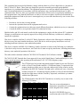
7802 WiFi Terminal
Portable WiFI Data Collection Terminal
Worth Data®
7800 Series
Host Controlled
WiFi Terminal System
Owner's Manual
Quick Start Guide
www.worthdata.com
Copyright © 2012, Worth Data, Inc.
1
This equipment has been tested and found to comply with the limits for a Class A digital device, pursuant to
Part 15 of the FCC Rules. These limits are designed to provide reasonable protection against harmful
interference in a residential installation. This equipment generates, uses and can radiate radio frequency energy
and, if not installed and used in accordance with the instructions, may cause harmful interference to radio
communications. However, there is no guarantee that interference will not occur in a particular installation. If
this equipment does cause harmful interference to radio or television reception, which can be determined by
turning the equipment off and on, the user is encouraged to try to correct the interference by one or more of the
following measures:
•
•
•
•
Reorient or relocate the receiving antenna.
Increase the separation between the equipment and receiver.
Connect the equipment into an outlet on a circuit different from that to which the receiver is connected.
Consult the dealer or an experienced radio/TV technician for help.
Shielded cables and I/O cords must be used with this equipment to comply with the relevant FCC regulations.
Changes or modifications not expressly approved in writing by Worth Data may void the user's authority to
operate this equipment.
This device complies with Part 15 of the FCC Rules. Operation is subject to the following two conditions: (1)
this device may not cause harmful interference, and 2) this device must accept any interference received,
including interference that may cause undesired operation.
This device complies with RSS-210 of Industry Canada. Operation is subject to the following two conditions:
1) this device may not cause interference, and 2) this device must accept any interference, including interference
that may cause undesired operation of the device.
The radio module contained within the 7802 Wi-Fi RF Terminal is Wi-Fi Alliance certified.
The 7802 Wi-Fi RF Terminals have been approved for use in the United States, Canada and Europe as a low
power spread-spectrum radio operating in the unlicensed 2.412-2.472 GHz frequency range.
The LT7802x has a laser scanner integrated with the Terminal as one unit. The laser
used is a Class II Laser Product and has a 1.2 Milliwatt Output. To operate the laser
scanner, aim the top of the case at a bar code, and press the yellow scan key on the
keyboard of the Wi-Fi RF Terminal. The light source will turn off, once a successful
scan has occurred or 2.5 seconds has elapsed, whichever is first. Do not look directly
into the laser light source with the "Scan Key" depressed; avoid direct eye contact
with the laser light source.
The LTnnnn models of the Wi-Fi RF Terminal are covered by one or more of the
following U.S. Patents:
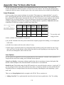
Patent #
4,496,831
4673,805
4,896,026
5,015,833
5,103,461
5,157,687
5,230,088
5,250,792
5,304,786
5,373,148
5,408,081
4,420,411
5,468,949
5,528,621
5,578,810
4,360,798
4,593,186
4,736,095
4,897,532
5017765
5,113,445
5,168,148
5,235,167
5,262,627
5,304,788
5,378,882
5,410,139
5,436,440
5,479,000
5,532,469
5,589,680
4,369,361
4,603,262
4,758,717
4,923,281
5,021,641
5,140,144
5,168,149
5,243,655
5,280,163
5,321,246
5,396,053
5,410,140
5,444,231
5,479,002
5,543,610
5,612,531
4,387,297
4,607,156
4,816,660
4,933,538
5,029,183
5,142,550
5,180,904
5,247,162
5,280,164
5,377,361
5,396,055
5,412,198
5,449,891
5,479,441
5,545,889
2
4,460,120
4,652,750
4,845,350
4,992,717
5,047,617
5,149,950
5,229,591
5,250,791
5,280,498
5,367,151
5,399,646
5,418,812
5,449,893
5,504,322
5,552,592
There are no user adjustments or
maintenance operations to be performed
on the integrated laser scanner.
The Wi-Fi CERTIFIED Logo is a
certification mark of the Wi-Fi Alliance.
Table of Contents
Introduction...................................................................................................................7
Differences....................................................................................................................7
Chapter 1: Installation..................................................................................................8
Components.........................................................................................................................................................8
Installation Sequence..........................................................................................................................................8
RF Terminal Operation........................................................................................................................................8
Using the RF Terminal keypad….........................................................................................................8
Battery Life Indicator............................................................................................................................9
To change the internal battery: .............................................................................................................9
Recharging the battery:.......................................................................................................................10
Installing the Wi-Fi RF Terminal Utilities Software.........................................................................................11
Using the Windows Integrated Hardware Utility................................................................................11
The Test Program…............................................................................................................................11
The Voice Manager….........................................................................................................................12
The Firmware Loader…......................................................................................................................12
Chapter 2: RF System Setup......................................................................................13
Factory Default RF Terminal Configuration.....................................................................................................13
Using the Setup Menu on the RF Terminal.......................................................................................................14
Wi-Fi Configuration.....................................................................................................................................15
Terminal Configuration............................................................................................................................15
Access Point Configuration.....................................................................................................................17
Connection Host Configuration...............................................................................................................19
Rev. 100 Mode.........................................................................................................................................21
Bar Code Options.........................................................................................................................................23
RS-232 Settings:...........................................................................................................................................26
Bluetooth Settings:.......................................................................................................................................27
Date & Time Setting.....................................................................................................................................28
Speaker Settings...........................................................................................................................................29
Laser Options................................................................................................................................................30
LCD Options................................................................................................................................................30
Other Settings...............................................................................................................................................31
System Tools.................................................................................................................................................33
Chapter 3: Operational Theory .................................................................................34
System Components..........................................................................................................................................34
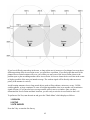
Architecture.......................................................................................................................................................35
Physical ..............................................................................................................................................35
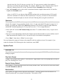
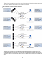
Communication Diagrams for Using a Connection Host................................................36
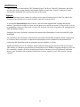
Communication Diagram for Using a “Cloud” Application Server.................................37
Logical................................................................................................................................................38
Communication.................................................................................................................................................39
How Site Survey works.....................................................................................................................................40
Performance Issues............................................................................................................................................40
3
Evaluating your area of planned operation...................................................................................................40
Chapter 4: Before You Begin Programming…..........................................................44
Overview...........................................................................................................................................................44
Plan Your Application.......................................................................................................................................44
Demo/Test Servers............................................................................................................................................45
Operational Configuration Options...................................................................................................................46
Failure Planning................................................................................................................................................47
Hardware Failures........................................................................................................................................47
Operator Errors.............................................................................................................................................47
Parts of the System............................................................................................................................................48
Install The Web-Based Connection Host..........................................................................................................50
Install Local Connection Host and Test Server.................................................................................................52
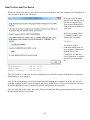
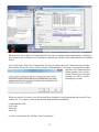
How To Use Local Test Server.....................................................................................................................54
Install Cloud Server...........................................................................................................................................57
How To Use The Cloud Server.....................................................................................................................58
Tutorials............................................................................................................................................................60
Cloud Server.................................................................................................................................................60
Connection Host...........................................................................................................................................61
Chapter 5: Programming for the RF Terminal .........................................................63
Operating Mode................................................................................................................................................63
Real-Time Mode...........................................................................................................................................63
Batch Mode..................................................................................................................................................64
Direct ASCII, Non Windows, and Cloud-Based Installations..........................................................................65
Terminal Native Command Reference..............................................................................................................66
HTTP / Low Level ASCII script sequences.................................................................................................66
Terminal Output Definition ................................................................................................................66
Terminal Receive Definition ..............................................................................................................67
Serial Reply.........................................................................................................................................75
SIGN ON.............................................................................................................................................75
SIGN OUT..........................................................................................................................................76
Connection Host Error Feedback........................................................................................................77
Illegal Command.................................................................................................................................77
Automatic Check Back.......................................................................................................................77
Control Keys for Possible Programming..........................................................................................................78
WD7802Term/ActiveX.....................................................................................................................................79
Programming Considerations.......................................................................................................................79
Concepts – WD7802Term ActiveX..............................................................................................................80
Properties – WD7802Term ActiveX.............................................................................................................81
Methods – WD7802Term ActiveX...............................................................................................................83
Events – WD7802Term ActiveX..................................................................................................................89
Chapter 6: Batch Programming.................................................................................92
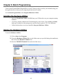
Installing the Hardware Utilities.......................................................................................................................92
Starting the Hardware Utilities..........................................................................................................................92
Statement Types Reference...............................................................................................................................94
Statement Details Reference.............................................................................................................................95
Data...............................................................................................................................................................95
4
Branch...........................................................................................................................................................95
Question........................................................................................................................................................95
Stamp (date and time Stamp).......................................................................................................................95
Time (time stamp)........................................................................................................................................95
Date (date stamp)..........................................................................................................................................96
Xtra...............................................................................................................................................................96
None.............................................................................................................................................................97
Compare.......................................................................................................................................................97
Print (printer output).....................................................................................................................................98
Arithmetic.....................................................................................................................................................99
Transmit Data...............................................................................................................................................99
Statement Field Details...................................................................................................................................100
Prompt Text................................................................................................................................................100
Voice Message Frequency..........................................................................................................................100
Voice Message Numbers............................................................................................................................101
Data ID.......................................................................................................................................................101
Data Type....................................................................................................................................................103
Maximum Data Length...............................................................................................................................103
Minimum Data Length...............................................................................................................................103
Input Device...............................................................................................................................................104
Yes/Next Statement....................................................................................................................................104
No/End Statement.......................................................................................................................................104
Upload Prefix..............................................................................................................................................104
Upload Suffix.............................................................................................................................................106
Chapter 7: Portable Printers....................................................................................107
Cameo and QL 3 Common Information..........................................................................................................107
Zebra Cameo Printer...................................................................................................................................107
Zebra QL 3 Printer......................................................................................................................................108
Chapter 8: Voice Message Operations....................................................................109
Why Use Voice Messages and Prompts?....................................................................................................109
Voice Prompts and the Worth Data Hardware Utilities program...............................................................109
Tips for Using Voice Prompts.....................................................................................................................109
Chapter 9: Troubleshooting......................................................................................111
General Considerations...................................................................................................................................111
Changing the Battery.........................................................................................................................111
Problems with a new installation:....................................................................................................................111
Terminal Error Messages.................................................................................................................................112
Troubleshooting specific problems.................................................................................................................113
I can’t communicate at all.................................................................................................................113
My response time is poor..................................................................................................................113
I'm not getting the distance I need.....................................................................................................113
Wi-Fi RF Terminal Problems......................................................................................................................114
When laser is triggered, it cycles power by itself – 1st screen.........................................................114
When a voice message plays, it cycles power by itself –1st screen..................................................114
When I turn it on, it just beeps continually.......................................................................................114
When I turn it on, the screen flashes continually..............................................................................114
5
I get 6 beeps when the Wi-Fi RF Terminal powers up......................................................................114
Problems reading Bar Codes......................................................................................................................114
The reader won't beep when I try to read bar codes..........................................................................114
I get extra characters at the beginning or end of my bar code data...................................................114
I have very poor read rates when scanning bar codes.......................................................................114
Problems with Voice Prompts.....................................................................................................................115
If you still have a problem…......................................................................................................................115
Appendix: Firmware Upgrades................................................................................117
Wi-Fi RF Terminal Firmware Upgrades................................................................................................117
Normal Firmware Download for a Terminal.....................................................................................117
Failsafe Firmware Download for a Terminal....................................................................................117
Appendix: Code 39 Specifications..........................................................................118
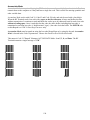
Code 39 Advanced Features and Functions ..........................................................................................118
Appendix: Code 93 Specifications..........................................................................121
Appendix: Codabar Specifications..........................................................................122
Codabar start/stop transmission........................................................................................................122
Appendix: Code 128 Specifications........................................................................123
Appendix: Interleaved 2 of 5 Code Specifications.................................................125
Appendix: UPC / EAN Specifications......................................................................126
ISBN Specifications..........................................................................................................................127
The UPC/EAN checksum character......................................................................................................127
Checksum calculation for UPC-A, EAN-13 and EAN-8..................................................................127
UPC-E Checksum Calculation..........................................................................................................128
Appendix: MSI/Plessey Specifications...................................................................130
Appendix: How To Scan a Bar Code.......................................................................132
Laser Scanners.......................................................................................................................................132
Aiming the Laser Dot:.......................................................................................................................133
"Difficult Code 39 Reading": ...........................................................................................................133
Appendix: Cable Pin-outs........................................................................................134
Appendix: ASCII Code Equivalent Table.................................................................136
6
Introduction
The 7802 Wi-Fi RF Terminal is a low cost, easy-to-use radio frequency interactive terminal which
communicates using the IEEE 802.11b/g protocol. It is designed to connect to a Wi-Fi network using an
access point or wireless router. This terminal offers unprecedented power and ease of use, while
maintaining compatibility with programs written for the older Worth Data Terminals. The list of features
include:
• Low Cost
• Spread Spectrum frequency hopping avoids interference
• No license required in USA, Canada or Europe
• Small size, (5.9" L, 3.6" W, 1.0" D) even with laser
• Certified to multiple 5 ft. drops to concrete
• Long Battery Life (15 hours of usage)
• Fast Recharging (2-3 hours) from External Power Supply
• No programming necessary on terminal
• User Customizable Voice Prompting plus Display
• Backlit Color 2.8” TFT Display Standard
• Uses Li-Ion battery
Differences
The 7802 uses the same screen formatting and prompt commands as the long range T7000. The major
difference between the 7802 and the T7000 is the radio and range. The 7802 uses a Wi-Fi radio that
communicates with Wi-Fi access points (APs) connected to a local area network (LAN). The T7000
connects to a R5000 Base Station connected to a single PC. The 7802 communicates with a host program
running on a server that is accessible over the internet. The T7000 communicates with a host program that
is running on the computer that is connected to the B5000 Base.
Here's a summary of the differences:
•
•
•
•
The 7802 has a range of a few hundred feet and the T7000 has a range of a few miles.
The 7802 works with most 802.11b/g access points or wireless routers, no B5000 required.
The host program for the 7802 can run on a server remote from the access point.
No fixed limit to the number of 7802 Terminals on a network. Each 7802 Terminal has a unique IP
address on the network.
7
Chapter 1: Installation
Components
The components in your Wi-Fi RF Terminal system will vary according to the configuration of your system.
Your Wi-Fi RF Terminal shipment should contain at least:
• A Wi-Fi RF Terminal T7802 or LT7802 - If the Wi-Fi RF Terminal is an LT7802 model, it will have an
integrated laser scanner built-in to the body of the terminal.
• USB Cable – for programming and voice prompt upload.
• 5V Power Supply – battery charger with adapter cable.
• Utilities CD ROM – demo programs, DLL, and firmware loader program
Installation Sequence
1. Before you begin setting up the Wi-Fi RF Terminal you will need to know some information about the
Wi-Fi network that it will be using. You will need the SSID and security type of the Wi-Fi network.
2. Now you can configure the Wi-Fi settings on the Wi-Fi RF Terminal. See Chapter 2 for more information
on the configuration of the Wi-Fi RF Terminal.
3.
4. Now run one of the demo programs to validate that everything is working. If you have problems, refer to
the Trouble Shooting Section.
RF Terminal Operation
Using the RF Terminal keypad…
The RF Terminal is turned on by pressing the green ON/OFF button located in the upper left-hand
corner of the RF Terminal keypad.
It is a good idea to fully charge the RF Terminal before you use it the first time to make sure the battery is
charged. See below for more information on battery charging.
The RF Terminal has a Shut Down Time feature that allows you to determine the length of time the RF
Terminal must be inactive before automatically shutting down to conserve battery power. When the RF
Terminal shuts down, simply press the ON/OFF button to resume operation.
The keypad is custom designed for RF Terminal operations. It has numeric and control keys in the nonshifted state, and alpha characters in its shifted state. Upper-case is the default mode after you press the
SHIFT key. If you need to enter a lower-case alpha character then press the F2 key and the cursor will
toggle between Red and Yellow. When the cursor is Red you will enter upper-case characters and when the
cursor is Yellow you will enter lower-case characters.
For all prompts which ask for a YES or NO response, the ENTER key, is the YES reply, and the 0 (zero) key
is the NO reply. As you key data, you will see each character displayed on the screen. If you make a
8
mistake, you can delete the last character by pressing the DELETE key, or you can clear all characters
displayed on the screen by pressing the CLEAR key.
Battery Life Indicator
The Wi-Fi RF Terminal detects low battery and displays the following message:
LOW BATTERY
Charge Battery
Hit Any Key_
At this point you have approximately 10% of battery life remaining. You should complete what you are
doing and charge the battery soon. When the battery is too low to operate the unit properly another message
is displayed:
Battery too Low to Operate
Hit Any Key to Power Down
If you turn it back on without charging batteries, you may experience constant beeping, intermittent scanning,
and very irritating symptoms that look like equipment failure.
The Wi-Fi RF Terminal also has a battery life indicator that can be accessed while operating. To display the
remaining battery life of the battery (as well as the date and time) press the STATUS key:
mm/dd/yy hh:mm:ss
BATTERY: |||||||||||||||||||| zz%
zz=percent in numbers i.e. 99, 10, 05
Press the STATUS key again to resume processing.
The lifetime of the Wi-Fi RF Terminal's Li-Ion battery is 500-1000 charge cycles. If the battery runtime
seems to be significantly shorter than when the device was new, the battery should be replaced. If you have
the optional “gun” handle with the extended battery then both batteries should be replaced at the same time.
The main battery is a common digital camera battery sold as Fujifilm NP-120 or Pentax D-LI7. We use a
high quality Japanese Li-Ion cell in our OEM pack that we supply with the Wi-Fi RF Terminal. You can
obtain a replacement from Worth Data (P/N: L02) . Our pack is rated at 1950 mAh and provides the longest
runtime available. Do not use a battery pack of unknown quality or origin. Doing so can risk damage to your
unit. The optional handle battery is custom made for Worth Data and must be ordered from us.
Your old battery should be recycled. You can get free recycling information at: http://www.rbrc.org/
To change the internal battery:
1. Turn OFF the Wi-Fi RF Terminal.
2. Remove the battery holder door on the back of the Wi-Fi RF Terminal by removing the two screws holding
the door in place..
3. Remove the old battery and insert a new one, making sure to orient the battery with the battery
contacts facing the battery connector.
4. To replace the optional handle battery, remove the 2 screws holding the handle in place. Unplug the
9
handle battery assembly.
5. Replace the battery door and screws and turn the reader on using the ON/OFF switch.
6. It is a good idea to fully charge the new battery(s) before first use.
Recharging the battery:
1. With the RF Terminal shut off, plug the 5V power adapter into the RF Terminal using the supplied
adapter cable.
2. The RF Terminal will turn On and display the following message:
Charging Battery
Please Wait………..
3. When the battery is fully charged after 2-4 hours the following messaged is displayed:
Battery Charge
Complete
4. The unit will remain ON for a half hour or so after the charge cycle has completed and then turn
OFF.
5. If you press the POWER key while the unit is charging, nothing will happen.
6. If you press the POWER key after the unit has turned OFF after completing a charge cycle and the
charger is still attached, the “Charging Battery” message will display again and a charge cycle will
begin.
7. It will take about 2 hours to fully charge a unit with a single battery and about 4 hours to fully charge
a unit with the optional handle battery.
8. Do not charge the battery if the Terminal is very hot or very cold since this will give a false reading
on the condition of the battery and it may not get charged properly.
9. You cannot operate the unit when the charger is attached, except to charge the battery.
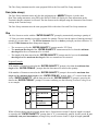
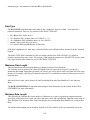
Wi-Fi RF Terminal Menu Functions
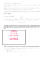
Upon power-up, the Wi-Fi RF Terminal displays the following opening screen:
Wi-Fi LT7802 - xxxx-Hyy-zzzz
Host:000.000.000.000:0000
Term:000.000.000.000:0000
SSID:
1. SIGN ON
2. SETUP
3. SITE SURVEY
(The opening screen can be bypassed upon power up. See Chapter 2)
•
•
•
•
•
On first line on the screen, xxxx, gives the firmware revision number.
Hyy indicates the version of the hardware.
The Wi-Fi security type is shown at zzzz.
Host: is the host server IP address.
Term: is this Terminal's IP address (all 000's for DHCP).
10
•
•
•
•
SSID is the name of the network that this terminal will connect to.
Press the 1 key to SIGN ON to a host computer program through an access point.
Pressing 2 enters the Setup Mode for the Wi-Fi RF Terminal.
Press 3 to scan for access points that are within range of the Wi-Fi RF Terminal.
You can back-out of any mode or prompt by pressing the F1 key. For example, if you select SETUP MODE
but really want SIGN ON, press the F1 key to take you back to the previous menu. The F1 key on the Wi-Fi
RF Terminal keypad works like the ESC key on the PC – it will usually get you out and back to the previous
step.
The entire mode menu can be skipped (see Chapter 2; Wi-Fi System Setup), causing the Wi-Fi RF Terminal
to automatically SIGN-ON when turned-on.
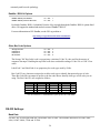
Installing the Wi-Fi RF Terminal Utilities Software
The RF Terminal system ships with a CD of programs for use with the RF Terminal and other Worth Data
hardware.
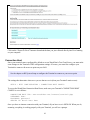
You have the choice of installing the following:
Windows Integrated Utilities
• Installation Test Program
• Voice Prompts Manager
• Programming Examples, and Demos
• Firmware Updater/Loader
ActiveX Tools
• Programmer's Development Tools
• Connection Host software
• Examples
Documentation
• Hardware manual for the 7802 Terminal
Click on the program you wish to install.
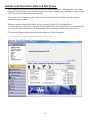
To install any of the programs found on the Utilities CD, simply insert the CD into your CDROM drive. The
install program should start automatically. If it does not, simply run the SETUP.EXE program found on the CD.
Using the Windows Integrated Hardware Utility
The Integrated Hardware Utility includes software tools, samples, and manuals for the 7802 Terminal.
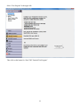
The Test Program…
Worth Data provides a test server available over the Internet. The Wi-Fi Terminal is shipped with default
Connection Host configuration that will connect to our test server once you have configured the Terminal's
11
WiFi configuration for your LAN/access point. This is a simulated data collection application that can be
used to test your installation or to demonstrate how the 7802 Terminal system works. See chapter on RF
System Setup for more on configuring your Terminal.
As part of the Integrated Utilities, Worth Data also provides a complete stand-alone testing system that will
run on your LAN and does not require Internet access. Using this test program requires more detailed
configuration of your Terminal(s). Please read the instructions presented in the test program when you run
it.
The Voice Manager…
This utility allows you to customize the voice prompts available in the 7802 Terminal for your application.
The Firmware Loader…
The 7802 RF Terminal Firmware Loader program is a part of the Integrated Utilities that allows you to
download new RF Terminal firmware from Worth Data into your RF Terminal. New firmware can be
obtained on CD ROM directly from Worth Data or downloaded via the Web at:
http://www.barcodehq.com/downloads.html
See Appendix: Firmware Upgrades for details on how to use the 7802 RF Terminal Firmware Loader
program (Windows).
12
Chapter 2: RF System Setup
The Wi-Fi RF Terminal can be configured using the Wi-Fi RF Terminal Setup menu. Most users do not need
to change anything in the setup except for the Wi-Fi settings.
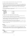
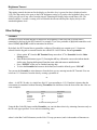
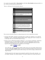
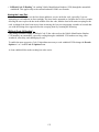
Factory Default RF Terminal Configuration
Parameter
Default Setting
Parameter
Default Setting
Wi-Fi Config
see details below for
MSI /Plessey
Code
MSI - OFF
Wi-Fi Configuration settings
and defaults
MSI with 1 mod 10 - OFF
MSI with 2 mod 10 - OFF
MSI with mod 11/mod 10 - OFF
Transmit check digit - 0
Plessey - OFF
Code 3 of 9
Code 39 - ON
Codabar
Codabar - OFF
Full ASCII - ON
CLSI format - OFF
Accumulate Mode - ON
START STOP Char - OFF
Transmit Start Stop - OFF
Code 128
MOD 43 Check Digit - OFF
Transmit MOD 43 - OFF
Code 128 - ON
UCC/EAN-128 - OFF
Databar / RSS-14
Databar / RSS-14 - OFF
Code 93 / Code
11
Code 93 - OFF
Caps lock - OFF
Decode Option - 0
2 of 5 Code
Interleaved 2 of 5 - OFF
Check Digit - OFF
Transmit Check Digit - OFF
Code 11 - OFF
Standard 2 of 5 - OFF
2 of 5 Length - 06
UPC-A EAN 13
UPC/EAN ALL - ON
Code 11 Check Trans - 0
RS-232 I/O
Settings
Baud Rate - 9600
Parity - none
Supplements - OFF
Data bits - 8
UPC-A NSC - ON
XON/XOFF Printer - ON
UPC-A check digit transmitted - ON
Time & Date
Settings
Date Format - USA
Speaker Options
EAN-13 Check - ON
Beep Volume - medium
Beep Tone - 2
ISBN EAN-13 mode - OFF
Voice Volume - medium
EAN-13 country code transmitted - ON
UPC-A as EAN-13 - OFF
UPC-E EAN 8
Code 93 full ASCII - ON
UPC-E First Char - OFF
Year Output – 2 digits
Shut Down Time – 5 min
Keypad Tone - ON
Laser Options
Double Decode - OFF
EAN-8 First Char - ON
4.5 Second Beam - OFF
UPC-E Check Digit - OFF
Aiming Dot Duration – 0 seconds
EAN-8 Check Digit - ON
UPC-E Expanded Transmission - OFF
LCD Settings
UPC-E1 - OFF
Other Bar Code
Options
Background Color – 1 (black)
Storage Tek Label – OFF
LabelCode 5 - OFF
Text Color – 2 (blue)
LabelCode 4 - OFF
Brightness – medium
Barcode IDs - OFF
Brightness Timeout – 5 sec
13
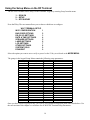
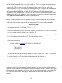
Using the Setup Menu on the RF Terminal
The Wi-Fi RF Terminal can be setup via the Terminals' keypad by entering Setup from the menu.
1. - SIGN ON
2. - SETUP
3. - SITE SURVEY
Press the 2 key. The next menu allows you to choose which item to configure:
Wi-Fi TERMINAL SETUP
Wi-Fi CONFIGURATION
BAR CODE OPTIONS
RS-232 I/O SETTINGS
DATE & TIME SETTINGS
SPEAKER SETTINGS
LASER SETTINGS
LCD SETTINGS
OTHER SETTINGS
SYSTEM TOOLS
DONE/EXIT
1
2
3
4
5
6
7
8
9
0
Select the option you want to set or verify or press 0 or the F1 key to exit back to the MODE MENU.
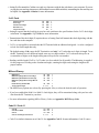
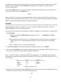
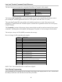
The groups in the keypad Setup Menu contain the following setup parameters:
Setup Group
Wi-Fi Setup
1
Parameter
Terminal Configuration
Host Configuration
Bar Codes
2
Code 3 of 9
UPC-A, EAN 13
UPC-E, EAN 8
Code 128
2 of 5 Codes
Codabar
MSI/ Plessey
Code 93 / Code 11
Databar / RSS / Other
RS-232
3
Date/Time
4
Baud Rate
Parity
Data Bits
XON/XOFF Printer
Setup Group
Speaker
5
Parameter
Beep Volume
Beep Tone
Voice Volume
Keypad Tone
Laser
6
Double Decode
4.5 Second Laserbeam
Aiming Dot Duration
LCD
7
Background Color
Text Color
Brightness
Brightness Timeout
Other
8
Set Time
Set Date
Date Format
Year Output
Shut Down Time
Preamble
Postamble
Characters
Once you have selected a group to edit, you will see each parameter displayed in the order listed above. Use
the next section of this chapter as a reference for all Wi-Fi RF Terminal Setup Parameters.
14
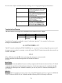
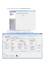
Wi-Fi Configuration
Under Wi-Fi Configuration there are three sections:
Wi-Fi CONFIGURATION
TERMINAL CONFIGURATION
ACCESS POINT CONFIG
CONNECTION HOST CONFIG
1
2
3
Terminal Configuration
DHCP
ON
Default: ON
Description
Sets the Terminal to either obtain and IP address, network mask, gateway, etc. from a DHCP server, or to use
static settings that you enter into the Terminal.
DCHP servers typically run on your LAN, not on the internet. Most LANs use a DHCP server. You can see
if yours does by looking at the network configuration of your computer; if it is set to “automatic” or similar,
chances are you have a DHCP server on your LAN. If you have an installed DSL modem, for example,
these typically have a default DHCP server running on them.
Whether you have a DHCP server running on your LAN or not is entirely up to you and is part of your
network configuration. If you don't understand what this is, you should consult with a person knowledgeable
about your network configuration.
Options
OFF or ON
Terminal IP Address
000.000.000.000
Default: 000.000.000.000
Description
If you set DHCP (above) OFF you will need to set a unique static IP address for your Terminal. If you have
more than one Terminal, each will require its own unique IP address. Keep in mind that every device and
computer on your LAN has its own unique IP address and you will cause problems if any two devices try to
use the same IP address. For example enter 192.168.1.12 (do not use leading zeroes, ie. do NOT enter
192.168.001.012).
Be aware that you cannot simply enter any combination of numbers here. First, it must be in the format
shown in the default, with four triplets (value from 0 to 255) separated by periods. Do not use leading zeros
in the triplets. Also, in order to be visible on your LAN, it must be on the correct “subnet”. What subnet you
are on is determined in part by your Network Mask, which basically tells you which part of your IP address
must be constant, and which can be unique for each device on your LAN. Almost all LANS use a network
mask of “255.255.255.0” and IP addresses something like “192.168.1.x”. What the network mask with three
15
“255”s tells us is that all of the IP addresses on your subnet must have the same first three triplets (ie
“192.168.1”) and that the fourth triplet can be any value from 1 to 255. All of the devices on your LAN with
an IP address that starts with “192.168.1” will be visible to each other. If there is a device with an IP address
of “192.16.2.5”, it is on a different subnet and will not be visible to all the “192.168.1.x” devices.
For clues as to what network mask and IP addresses you can use, you can look at the network setting on
your computer to see how it is set up.
Of course, by far the easiest way to set this is use DHCP!
Options
A valid IP address of the form 123.456.789.12
Enter the digits leaving out any leading zeros. For example enter 192.168.1.12 not 192.168.001.012.
Value range for each triplet is 0-255.
Interacts with “Network Mask” setting below. See comments in Description above.
Network Mask
255.255.255.000
Default: 255.255.255.000
Description
If you set DHCP (above) OFF you will need to determine and set the proper Network Mask for you LAN.
Network Mask helps to determine the subnet your LAN is operating on. All devices on your LAN must have
the same Network Mask setting in order to be visible to each other. Read the description in Terminal IP
Address above for more on Network Masks and Subnets.
The Network Mask is entered in exactly the same form as an IP address, with 4 triplets separated by periods.
If you are unsure of what you are doing, don't change anything until you consult with someone
knowledgeable in network addressing.
As an interesting aside, yes, you can have multiple subnets all operating on the same physical network, all
running independently and invisible to each other.
Options
A valid IP number of the form 255.255.254.0
Enter the digits leaving out any leading zeros. For example enter 192.168.1.12 not 192.168.001.012.
Value range for each triplet is 0-255.
Interacts with “IP Address” setting above. See comments in IP Address Description above.
Gateway IP Address
000.000.000.000
Default: 000.000.000.000
Description
The gateway IP address is required if the Terminal will be communicating outside of your local LAN, that
is, if the Terminal will be connecting with a Connection Host running on the internet or another subnet.
16
The gateway IP address is generally the IP address of your DSL or cable modem/router on your LAN.
Options
In most cases, the gateway address is supplied by a DHCP server, but if not you can enter one. A typical
address is 192.168.0.1; you can check your computer settings and match that.
DNS Server IP Address
000.000.000.000
Default: 000.000.000.000
Description
A DNS server is any computer registered to join the Domain Name System. A DNS server runs specialpurpose networking software, features a public IP address, and contains a database of network names and
addresses for other Internet hosts.
A DNS server is usually hosted by an internet service provider, running on the internet. It is possible you
have a local DNS server running on your LAN (but if you do you probably know exactly what you are
doing and don't need to read this).
DNS servers resolve website names like “www.barcodehq.com” into an actual internet address code (an IP
address) like “68.142.213.151”. You can see that the IP address works just like the name by entering the IP
address in your browser.
Options
If your Connection Host address is a name rather than an IP address number, then you will need to make
sure you have specified the DNS Server Address.
If you have DHCP enabled, most DHCP servers provide the DNS server setting. If you are not using DHCP,
the easiest way to find out your DNS server address is to review your computer's network summary details.
If you are having difficulty determining what you need to put here, or finding the DNS server address
setting on your computer, you will need to consult with someone familiar with these settings.
Access Point Configuration
SSID
<blank>
Default: <blank>
Description
The SSID, or Service Set IDentification, is the code name your WiFi router broadcasts to identify the name
of the network it supports. Some installation “hide” the SSID, that is the WiFi router is set to not broadcast
it. In this case, you still need to know what it is.
Options
Set the SSID to match the SSID of the network that the Terminal will be connected to. If the SSID is not
17
hidden, you can use the SITE SURVEY command at the opening screen to find the SSID of Wi-Fi networks
that are in range.
The SSID must be entered in the Terminal EXACTLY as it is set in the WiFi router (and as shown in the Site
Survey described above). This means all upper- and lower-case letters and number must match exactly.
When setting the SSID the cursor will change to a white box. Press the light blue shift key to enter uppercase alpha characters. Press the F2 to toggle upper and lower-case entry. The red cursor is for upper-case,
the yellow cursor is for lower-case and the white cursor is for non-shifted characters from the number pad.
SECURITY
NONE
Default: NONE
Description
Security is the encryption method used by your WiFi router/access point to protect transmitted and received
data from unauthorized monitoring. By default, most access points are set to use no encryption.
The SECURITY setting in your Terminal must match the security set in your WiFi access point that the
Terminal will be communicating with.
The configuration system for most access point will have encryption descriptions that do not match exactly
the choices provided in the Terminal. Some access points will support encryption modes that the Terminal
does not support, and vice-versa.
Options
NONE
WEP-128
WPA1-PSK-TKIP
WPA-PSK (mixed WPA1 and WPA2)
WPA2-PSK-AES
The default is no security. WEP-128 only supports Open System Authentication. Pressing the 4 key will
toggle through the available choices. WPA1 and WPA2 are the most common types. If you are unsure, try
what appears to most closely match your access point setting. If you experience problems, try temporarily
turning off security on your access point and Terminal to make sure security issues are not preventing a
connection.
KEY/PHRASE
<blank>
Default: <blank>
Description
This is the security “password” to match the setting in your WiFi access point.
Options
For WEP-128 enter the hex key. For WPA enter the pass phrase. See the above “SSID” for how to enter
18
upper- and lower-case characters.
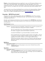
Connection Host Configuration
Connection Host URL
www.worthdata.net/server/cloud.php
Default: www.worthdata.net/server/cloud.php
Description
This is the web address/URL or IP address (must have DNS Server set if using a URL) where a Connection
Host is running.
The Connection Host program can be running on a computer on your LAN , in which case you will use the
IP address of the computer running the Connection Host program, or the Connection Host can be running on
a web server, in which case you can use either an IP address or the URL of the web server Connection Host
an IP address.
This can also be the web address/URL of an integrated web-based application, or “Cloud Server” that wraps
the function of the Connection Host and a task-specific data-driven custom application all in one. The
default setting on your Terminal points to a demonstration Cloud Server on the Worth Data website.
Complete source code for both the demo Cloud Server and the web-based Connection Host are provided
with your Terminal.
Options
Worth Data provides a web-based Connection Host that you can use at
www.worthdata.net/connect/terminal.php
A Windows-based Connection Host program that you can install on a computer on your LAN for a
completely local solution is also provided with the Terminal.
Set this to the address/URL of a Cloud Server or the terminal interface of a Connection Host located on the
Internet (web-based)
or
Set this to the IP address on your LAN of the Windows Connection Host application.
Keep in mind that the web-based solutions can also be run on a private/local web server such as Apache or
IIS, if you have one available and the resources to configure it.
Leave out any leading zeros. For example enter 192.168.1.5 not 192.168.001.005.
Connection Host Port Number
80
Default: 80
Description
19
The Port Number is part of the address of the Connection Host and is used in addition to the Connection
Host URL above. Think of the port number as like a PO Box number in a mailing address.
By using different ports, a single computer running on a single IP address can support multiple server
functions, for example it can be an FTP server (port 21), an HTTP web server (port 80), a telnet server (port
23), a SMTP mail server (port 25), etc.
Options
The default setting of 80 allows the Terminal to connect with Worth Data's demo “cloud application”
running on the worthdata.net website. If you are running your own web-based connection host or cloud
server, you will probably want to use 80 as well.
If you want to use the Windows-based Connection Host program running on your LAN, you will probably
need to use a port other than 80 (current versions of Windows typically prevent application from using port
80). When you run our Windows-based demos, port 8080 is suggested and used by default.
In general, set the Host Port Number to match the port being used by the Connection Host. If you are
running the Connection Host program locally on your LAN rather than using the Worth Data internet-based
connection host or your own internet-based connection host installed on your web site, this will need to be
set to other than 80 (try 8080 and the Connection Host program set to match). Otherwise, do not change
unless you know exactly what you are doing.
User Name
demo
Default: demo
Description
Part of Application Server access key system. In order to connect with an Application Server, settings for
User Name, Server ID, and Password must all be set identically in the Application Server and all Terminals
that use this Application Server.
The Connection Host does not use this setting and simply passes the User Name on to connected Terminals
and Application Servers.
Note: Application Servers are custom programs you build using the provided ActiveX control. “User Name”
is one of the required properties to set in the ActiveX control.
Options
Enter any text you like here (up to 12 characters), as long as exactly the same User Name is set in the
Application Server you want the Terminal to connect with.
Password
password
Default: password
Description
Part of Application Server access key system. In order to connect with an Application Server, settings for
User Name, Server ID, and Password must all be set identically in the Application Server and all Terminals
20
that use this Application Server.
The Connection Host does not use this setting and simply passes the User Name on to connected Terminals
and Application Servers.
Note: Application Servers are custom programs you build using the provided ActiveX control. “Password”
is one of the required properties to set in the ActiveX control.
Options
Enter any text you like here (up to 12 characters), as long as exactly the same Password is set in the
Application Server you want the Terminal to connect with.
Server ID
Worth Data Demo
Default: Worth Data Demo
Description
Part of Application Server access key system. In order to connect with an Application Server, settings for
User Name, Server ID, and Password must all be set identically in the Application Server and all Terminals
that use this Application Server.
The Connection Host does not use this setting and simply passes the Server ID on to connected Terminals
and Application Servers.
Note: Application Servers are custom programs you build using the provided ActiveX control. “Server ID”
is one of the required properties to set in the ActiveX control.
Options
Enter any text you like here (up to 12 characters), as long as exactly the same Server ID is set in the
Application Server you want the Terminal to connect with.
Rev. 100 Mode
Default: OFF
Description
Allows compatibility with earlier versions of the 802 and 7802 “version 100” Terminals. These terminals
use a different communication protocol that the current 7802 WiFi Terminals and require the version 1
Windows-based Connection Host. Early version Terminals cannot use the web-based Connection Host.
The ActiveX component used by these earlier version Terminals is also different, though the programming
interface is almost identical and the old and new ActiveX components can be installed and run together in
your Server Application thus allowing you to run old and new Terminals together.
The rev. 100 mode uses a completely different protocol to communicate with the Connection Host (must be
a version 1 Connection Host) and Application Server, relying on UDP broadcast and proprietary
handshaking routines.
21
The normal operating mode of the 7802 terminal (with rev. 100 mode turned OFF) uses standard TCP
connections and HTTP data formatting.
Rev. 100 mode is intended ONLY FOR BACKWARD COMPATIBILITY and should NOT be used for
developing new applications. Existing applications that use the older terminals can be easily ported to
accommodate both old and new 7802 terminals. Please review the sample applications, ActiveX
programming tools, and documentation that comes with your 7802 terminal.
Options
Set Revision 100 Compatibility Mode for the terminal to operate as an original “802” terminal or as a “rev.
100” (first edition) version of the 7802 terminal.
22
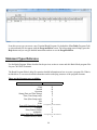
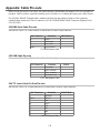
Bar Code Options
Code 3 of 9 (Code 39)
Code 3 of 9
Full ASCII
Accumulate Mode
Transmit Start Stop
MOD 43 Check Digit
Transmit MOD 43
Caps Lock
Decode Option
ON
ON
ON
ON
ON
ON
ON
OFF
OFF
OFF
OFF
OFF
OFF
OFF
0, 1, 2
1
2
3
4
5
6
7
8
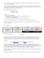
• The Start and Stop character for Code 39 is the * character. Setting 4 determines whether or not those
characters are transmitted to the computer along with the data. For example, at setting ON, the data of
1234 would be transmitted as *1234*. Transmitting the start and stop characters can be useful if you need
to differentiate between data that comes from a bar code versus data coming from the keypad.
• Enabling use of the Mod 43 check character requires that the last character of your bar code conform to the
Mod 43 check character specifications. See Appendix: Code 39 for more information. Enable
transmission (6) will send the check digit data along with the rest of the bar code data to your computer.
To use 6, you must also be using 5.
• Caps Lock ON causes lower case letters read as data to be transmitted to the computer as UPPER CASE,
and upper case letters to be transmitted as LOWER CASE. Numbers, punctuation and control characters
are not affected. Caps Lock OFF means that letters will be transmitted exactly as read. This setting applies
to all bar code types.
• See Appendix: Code 39 for more information regarding Accumulate Mode.
• Decode Option is used to allow reading of Code 39 bar codes through a windshield. Setting this option to 1
will loosen up the decoder a little and option 2 will loosen up the decoder a bit more. This should be used
with caution since using a looser decoder can cause substitutions.
UPC-A / EAN-13
UPC/EAN ALL
UPC/EAN Supplements
UPC-A NSC
UPC-A Check
EAN-13 First 2 Digits
EAN-13 Check
ISBN EAN-13 Mode
UPC-A as EAN-13
ON
ON
ON
ON
ON
ON
ON
ON
OFF
OFF
OFF
OFF
OFF
OFF
OFF
OFF
1
2
3
4
5
6
7
8
• Use setting 2 to enable reading of the 2 and 5 digit UPC/EAN supplements commonly found on magazines
and paperback books as well as the Extended Coupon Codes. Using this setting force left to right reading
of UPC codes to assure that the supplement code is not missed.
• Use setting 3 to enable transmission of the NSC character to your computer. The Number System
Character is the leading character in the bar code. For details, see Appendix: UPC/EAN.
• Use setting 4 to enable transmission of the check digit character to your computer. The check digit is the
last character and is based upon a calculation performed on the other characters.
23
• Use setting 5 to enable the transmission of the EAN-13 country code (the first 2 digits).
• Use setting 6 to enable the transmission of the EAN-13 check digit.
• ISBN (International Standard Book Numbering) bar codes are EAN-13 with a 5-digit supplement. If the
“Bookland” bar code uses 978 (books) or 977 (periodicals) as the first three digits, then the RF Terminal
can transmit it in the ISBN format. To enable transmission of the ISBN format, set option 7 to ON. To
return to the default of normal EAN-13 transmission, set option 7 to OFF. For details on ISBN, see
Appendix: UPC/EAN.
• UPC-A can be transmitted in EAN-13 format by adding a leading 0 (USA county code) to the UPC-A data.
To transmit in EAN-13 format, set option 8 to ON.
UPC-E / EAN-8
UPC-E First Digit
EAN-8 First Digit
UPC-E Check Digit
EAN-8 Check Digit
UPC-E Expanded
UPC-E1
ON
ON
ON
ON
ON
ON
OFF
OFF
OFF
OFF
OFF
OFF
1
2
3
4
5
6
• Use setting 1 and 2 to enable or disable the UPC-E or EAN-8 first digit.
• Use setting 3 and 4 to enable or disable the UPC-E or EAN-8 check digit. The check digit is the last
character and is based upon a calculation performed on the other characters.
• Use setting 5 to select UPC-E0 compressed or expanded. When set to ON (the default setting) UPC-E1
codes are transmitted as is, when set to OFF UPC-E1 codes are transmitted with inserted zeros to make
them the same length as a UPC-A bar code. An NSC of 0 is assumed.
• Use setting 6 to enable the reading of UPC-E1 bar codes. Do not enable UPC-E1 if you plan on reading
EAN-13 bar codes. You may experience partial reads when reading ENA-13.
• If you prefer to transmit UPC-E bar codes in a 6-digit format while EAN-8 is transmitted in its original 8digit format, set option 7 to ON.
Code 128
Code 128
UCC/EAN 128
ON
ON
OFF
OFF
1
2
• UCC/EAN-128 is a subset of Code 128 that follows certain specifications regarding character content,
length and check digits. Enabling UCC/EAN-128 (2) causes the RF Terminal to look for a Code 128 bar
code that begins with the Code 128 F1 (Function 1) character. See Appendix: Code 128 for more details.
Codabar
Codabar
Codabar CLSI
Start Stop Character
ON
ON
ON
OFF
OFF
OFF
• CLSI is a form of Codabar often used by libraries.
24
1
2
3
• Setting 3 will transmit the Codabar start and stop characters with the bar code data to your computer. If you are
varying the start and stop characters to differentiate between different labels, transmitting the start and stop can
be helpful. See Appendix: Codabar for more information.
2 of 5 Code
Interleaved 2 of 5
Check Digit
Transmit Check Digit
Standard 2 of 5
2 of 5 Code Length
ON
ON
ON
ON
OFF
OFF
OFF
OFF
06
1
2
3
4
5
• Setting 2 requires that the last digit in your bar code conform to the specifications for the 2 of 5 check digit
calculation. See Appendix: 2 of 5 Code for more information.
• Transmission of the check digit (3) requires the use of setting 2 and will transmit the check digit along with the
bar code data to the computer.
• 2 of 5 is so susceptible to misreads that the RF Terminal adds an additional safeguard - it can be configured
to look for fixed-length data only.
• The default setting of 06 causes the RF Terminal to read only 2 of 5 codes that are 6 digits in length. To set
the RF Terminal to read a different length, enter any two-digit number. 2 of 5 code must always be an
even number of digits so the length setting must always be an even number.
• Reading variable length I 2of5 or 2 of 5 codes is to be avoided if at all possible. The 00 setting is supplied
for the purposes of reading codes of unknown length, counting the digits and setting the length to the
proper number.
MSI and Plessey
MSI/Plessey
MSI/Plessey-Single Mod 10 Check Digit
MSI/Plessey-Double Mod 10 Check Digit
MSI/Plessey-Single Mod 11/Single Mod 10
Check
Enable Plessey / Disable MSI
Transmit Check Digits
ON
ON
ON
ON
OFF
OFF
OFF
OFF
1
1
1
1
ON OFF
0, 1 or 2
1
2
• The MSI/Plessey options are selected by pressing the 1 key to select the desired mode of operation.
• If you have enabled the Mod 10 or Mod 11 check digits, they will be transmitted along with your bar code
data from the RF Terminal to your host.
• For more information regarding MSI or Plessey Code, see Appendix: MSI Plessey Code.
Code 93 / Code 11
Code 93
Code 93 Full ASCII
Code 11
Code 11 Check Digit Transmission
ON OFF
ON OFF
ON OFF
0, 1 or 2
1
2
3
4
• Code 93 is similar in character set to Code 39. See Appendix: Code 93 for more information. Code 93 is not a
25
commonly used bar code symbology.
DataBar / RSS-14 Options
DataBar / RSS-14
DataBar / RSS-14 plus Identifiers
DataBar / RSS-14 plus UCC-128 Format
ON
ON
ON
OFF
OFF
OFF
1
1
1
By default, DataBar / RSS-14 is disabled. Press the 1 key to toggle through the DataBar / RSS-14 options listed
above. We support the standard and stacked version of DataBar / RSS-14.
For more information on GS1 DataBar, see the GS1.org website at
http://www.gs1.org/productssolutions/barcodes/databar/
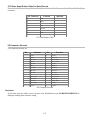
Other Bar Code Options
Storage Tek Label
LabelCode 5
LabelCode 4
Bar Code IDs
ON
ON
ON
ON
OFF
OFF
OFF
OFF
2
3
4
5
The Storage Tek Tape Label code is a proprietary variation of Code 39 code used for the storage of
computer data tapes. Enabling the tape label code does not disable reading of Code 128 or Code 39 bar
codes.
LabelCode 5 and LabelCode 4 are proprietary bar code types used by Follet.
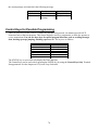
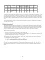
Bar Code ID’s are characters assigned to each bar code type to identify that particular type of code.
These Bar Code IDs can output as prefix to the bar code data to identify what type of bar code you are
using. The Bar Code ID’s are assigned as follows:
Bar Code
Codabar
Code 39
UPC-A
EAN-13
I 2of 5
ID
a
b
c
d
e
Bar Code
2 of 5
Code 128
Code 93
MSI
UPC-E(0)
ID
f
g
i
j
n
Bar Code
UPC-E (1)
EAN-8
RSS-14
StorageTek
Plessey
ID
o
p
r
s
x
Bar Code
LabelCode 4
LabelCode 5
ID
y
z
The ID character is transmitted in front of the bar code data.
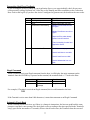
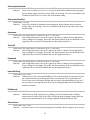
RS-232 Settings:
Baud Rate
Use the 1 key to select the baud rate. The default value is 9600. The available baud rates are 2400, 4800,
9600, 19200, 38400, 57600 and 115200.
26
Parity
• Use the 2 key to select the parity.
• The options are None, Even or Odd.
• None is generally used with 8 data bits
• Even or Odd parity is generally used with 7 data bits.
Data Bits
Use the 3 key to select either 8 or 7 data bits.
XON / XOFF Printer
• Setting 4 pertains to use of a serial Printer with your RF Terminal. Use key 4 to enable XON / XOFF if your
serial Printer supports it. It DOES NOT apply to the Cameo and QL3 Printers.
• Settings E and F pertain to the way the RF Terminal handles illegal statements coming from the host
computer. RF Terminal software versions prior to 9.059 did not handle illegal statements the same way as
current versions. This setting is really only applicable if you had written your host program to be
compatible with RF Terminal versions prior to RFT9059.
Bluetooth Settings:
The Bluetooth Settings menu has 4 options that allow the LT7802B to pair with other Bluetooth devices.
Currently only the Serial Port Profile (SPP) is supported. This is the most common profile for serial cable
replacement and is typically used for Bluetooth enabled printers.
Bluetooth Interface (On/Off)
This setting controls the power to the Bluetooth module and also sets the operation of the “S” command.
The Bluetooth interface is Off by default and must be set to On to use the Bluetooth module. The “S”
command will send data to the RS-232 port when the Bluetooth Interface is set to Off. The “S” command
will send data to the Bluetooth module when the Bluetooth Interface is set to On.
Add New Devices
Use this command to add a new Bluetooth device. The LT7802B can have up to 5 “known” devices at one
time and paired with 1 device at a time. The “Add New Devices” screen shows up to 5 devices that have
been added at the top of the screen and the names of up to 5 “found” Bluetooth devices at the bottom of the
screen. When the “Add New Devices” option is selected the LT7802B will scan for active Bluetooth
devices. You must make your Bluetooth device “discoverable” before the option is selected for the device
to be found. Consult the manual for your Bluetooth device to find out how to make it “discoverable”. You
can select any of the “found” devices to add to the list of known Bluetooth devices. If the LT7802B is
currently paired with a previously found Bluetooth device then (PAIRED) will appear next to the name of
that device. The LT7802B can only pair with one device at a time. You must pair the LT7002 with a
Bluetooth device before you can send data to that device.
27
Delete/View Devices
This command is used to see what Bluetooth devices are “known” by the LT7802B and delete them from
the list of known devices. If one of the devices is paired with the LT7802B then (PAIRED) will appear next
to that device. This is a quick way to see what device, if any, is currently paired with the LT7802B.
Pair with Existing Device
Use this command to pair the LT7802B with a Bluetooth device that has been found using the “Add New
Device” command. You must add the device before you can pair with the device. A list of previously
“found” devices will be displayed and the currently paired device, if any, will be indicated with (PAIRED).
Select the device that you would like to pair with or press 0 to exit and make no change.
The LT7802B will attempt to pair with the Bluetooth device when the S-command is sent so make sure that
your Bluetooth device is powered up and ready at that time.
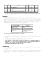
Date & Time Setting
Set Time
The time is set using a 4-digit military hhmm format. For example, to set the time to 3:08 p.m., you would
enter 1508. To display the time during operation, press the STATUS key.
Set Date
For correct date display, the 6-digit date must be set in the date format you plan to use. By default the US
terminals use the US date format of dd/mm/yy. If you change the date format, you must re-set the date to
match the new format. For example, to set a date of January 20, 2009, you would enter 012009 (US format)
or 200109 (European format). To display the date during operation, press the STATUS key.
Date Format
US Format
European Format
0
1
• The US format of mm/dd/yy is the default setting.
• If you switch formats, you must reset the date (SET DATE) in the new format also.
Year Output
2 digit
4 digit
0
1
• By default, the RF Terminal is configured to display and transmit the year in a 2-digit format; i.e. 2009
would transmit and display as 09.
• Before you change the RF Terminal to display a 4-digit year, i.e. 2009, make sure that the software
receiving data from the RF Terminal is set up to accept a 4-digit year.
Shut Down Time
By default, if the RF Terminal is inactive (no keystrokes or scanning) for more than 5 minutes, it will
shut itself down in order to conserve batteries. This includes SIGNING OFF if appropriate. To resume
28
operation, you must turn the RF Terminal back on using the ON/OFF key. To change the amount of time
the RF Terminal waits before shutting down enter two digits - the default is 05 (5 minutes)- to
correspond to the length of time in minutes. For example, 01 would be 1 minute. Setting the Shut Down
Time to 00 will disable automatic shutdown.
Speaker Settings
Beep Volume
OFF
Low
2
3
4
Medium
6
7
8
High
1
1
1
1
1
1
1
1
1
1
The default volume of the “Beep” is Medium. Each time you press the “1” key you will hear a
beep at the different volume settings. When you are happy with the loudness of the beep tone, press 0
or F1 to exit.
Beep Tone
1 - Lowest
2 - Low
3 - Medium
4 - High
5 - Highest
2
2
2
2
2
The default beep tone is 3 – Medium. Each time you press the “2” key you will hear a beep at
various tones. When you are happy with the tone of the beep, press 0 or F1 to exit.
Voice Volume
OFF
Low
2
3
4
Medium
6
7
8
High
3
3
3
3
3
3
3
3
3
3
The default volume of the “Voice” is Medium. Unless you need very loud voice prompts you should
use the medium setting to conserve battery power. When you are happy with the loudness of the
beep tone, press 0 or F1 to exit.
Keypad Tone
Keypad Tone
ON
OFF
4
The “Keypad Tone” is the key click that you hear each time a key is pressed. Press the “4” key to
toggle this On and Off.
29
Laser Options
Double Decode
Double Decode
ON
OFF
1
• Double Decode is there to minimize the possibility of misreads when scanning very poor quality bar codes.
This option forces the RF Terminal to keep reading until it gets two results that are identical. This "double scan
checking" takes longer but will minimize misreads since it must get the same result twice before considering it
a "good" read.
4.5 Second Laser Beam
4.5 Second Laser Beam
ON
OFF
2
• 4.5-second laser beam increases the amount of time the laser beam is activated, giving the laser more time to
try and read a code. This option is useful for trying to read poor quality code. The default beam time is 2
seconds.
Aiming Dot Duration
Aiming Dot Duration (in 1/10 seconds)
00 – 99
3
• This parameter applies to the built-in internal laser. Before the laser beam spreads, you can create a
brighter aiming dot to be sure you are on the bar code you want to read. The default is set to 00, no
aiming dot. You can key in 01 through 99 which creates an aiming dot in 1/10th second increments; i.e.,
20 would be two seconds.
LCD Options
Background Color
Background Color
0, 1, 2, 3, 4, 5, 6, 7, 8, 9, A, B, C, D, E, F
2
The default background color can be set to one of 16 different values. Each time you press the “2” key a small
rectangle will show the selected background color with the current text color. The default value is 1 for Black. You
can find more information about colors in chapter X.
Text Color
Text Color
0, 1, 2, 3, 4, 5, 6, 7, 8, 9, A, B, C, D, E, F
3
The default text color can be set to one of 16 different values. Each time you press the “3” key a small rectangle
will show the selected text color with the current background color. The default value is 2 for Blue. You can find
more information about colors in chapter X.
Brightness
Brightness
LOW, MED, HIGH
The default brightness of the LCD is medium which works well for indoor use. In high ambient light areas,
like outdoors, you may want to increase the brightness of the display. Increasing brightness shortens battery
life.
30
Brightness Timeout
Brightness Timeout (in seconds)
00..05..99
This setting controls the timeout for the display to dim after a key is pressed or data is displayed on the
LCD. The dim setting is the same as the LOW brightness setting so if you have the brightness above set to
LOW you will not see any effect from the timeout. Dimming the display helps extend battery life. The
default is 05 for 5 seconds. A setting of 00 will disable the timeout and keep the display always at the
standard brightness level.
Other Settings
Preamble
Preambles are user-defined data that is attached to the beginning of data (bar code or keyed) that is
transmitted to the host by the RF Terminal. For example, if you set a preamble of @@ and scanned bar code
data of 12345, @@12345 would be transmitted to the host.
By default, the RF Terminal has no preambles configured. Preambles can contain up to 15 characters
entered from the keypad or scanned from the bar coded FULL ASCII Menu. To set a preamble:
Select option “8” from the RF Terminal Setup menu then “1” for Preamble from the Other
Settings menu.
2. Enter the desired characters (up to 15). Pressing the shift key will turn the cursor red to indicate that the
shift is active. Pressing shift again will turn the cursor white and return to unshifted mode.
3. Press “ENTER”.when you are finished entering data.
4. To clear the Preamble and return to the default (no Preamble defined), press “CLEAR”.
1.
You can use the Preamble to trim characters from the data you are entering into the RF Terminal. You can
trim from 1-15 characters from the data by creating a preamble of:
~x
where ~ is ASCII 126 and x is a single hex digit 1-F (corresponding to 1-15). Data that is shorter than the
trim amount is transmitted without trimming. Preambles trim characters from the front of the data. Here are
some examples:
Data
123
12345678
12345678
12345678901
123456
Preamble
Data Transmitted
XYZ
XYZ123
~3XYZ
XYZ45678
~9
12345678
~A
1
~5
6
Preamble trims leading characters
Using the Bar Code ID feature and the Preamble, you can trim data selectively, trimming characters only on
the bar code type specified. To use selective trimming, enter:
~bx
where b is the Bar Code ID character (see the Code 128 setup parameter) and x is the number of characters to
31
trim from the front of the data. For example, ~b2~c1 says “trim 2 characters from Code 39 data and 1 character
from UPC-A data”. Remember that the Preamble trims leading data. This applies to One-Way and host
prompted communication.
Lastly, the Preamble can be used to check a minimum/maximum data length for bar code data entered. To
check for bar code length in the Preamble enter:
|nnmm
where | is ASCII 124, nn is the two-digit minimum and mm is the two-digit maximum. |0210 would check for a
minimum of 2 characters and a maxi-mum of 10. If you try to scan a bar code outside the minimum or maximum
lengths, no decode will result. Entering data by keypad is not affected.
Postamble
Postambles are user-defined data that is attached to the end of data (bar code or keyed) that is transmitted to
the host by the RF Terminal. For example, if you set a Postamble of @@ and scanned bar code data of
12345, 12345@@ would be transmitted to the host.
• By default, the RF Terminal has no Postambles configured. Postambles can contain up to 15 characters. To
set a Postamble:
1 Select option “8” from the RF Terminal Setup menu then “2” for
Settings menu.
Postamble from the Other
2 Enter the desired characters (up to 15). Pressing the shift key will turn the cursor red to indicate
that the shift is active. Pressing shift again will turn the cursor white and return to unshifted
mode..
3 Press “ENTER”.when you are finished entering data.
• To clear the Postamble and return to the default (no Postamble defined), press “CLEAR”.
• You can use the Postamble to trim characters from the data you are entering into the RF Terminal. You can
trim from 1-15 characters from the data by creating a Postamble of:
~x
where ~ is ASCII 126 and x is a single hex digit 1-F (corresponding to 1-15). Data that is shorter than the
trim amount is transmitted without trimming. Postambles trim characters from the end of the data. Here are
some examples:
Data
123
12345678
12345678
12345678901
123456
Postamble
Data Transmitted
XYZ
123XYZ
~3XYZ
12345XYZ
~9
12345678
~A
1
~5
1
Postamble trims trailing characters
• Using the Bar Code ID feature and the Postamble, you can trim data selectively, trimming characters only
on the bar code type specified. To use selective trimming, enter:
~bx
32
where b is the Bar Code ID character (see the Code 128 setup parameter) and x is the number of
characters to trim from the end of the data. For example, ~b2~c1 says “trim 2 characters from Code 39
data and 1 character from UPC-A data”. Remember that the Postamble trims trailing data.
• Lastly, the Postamble can be used to check a maximum character length for data entered. To check for
length in the Postamble, enter:
|nnmm
where | is ASCII 124, nn is the two-digit minimum and mm is the two-digit maximum. |0210 would
check for a minimum of 2 characters and a maximum of 10 If you try to scan a bar code outside the
minimum or maximum lengths, no decode will result. Entering data by keypad is not affected.
Characters
This setting allows the RF Terminal to output chosen ASCII characters in place of the actual characters
entered. For example, if you scanned the number 1 (hex 31) and wanted the RF Terminal to output hex 92
instead, you would enter 3192 for the Characters parameter. This would re-assign the output characters,
with the RF Terminal outputting hex 92 every time it sees hex 31. To re-assign characters:
• Select option “8” from the RF Terminal Setup menu then “3” to enable character entry. A square cursor
will appear.
• Enter up to seven 4-digit pairings where the first 2 digits represent the hex number to replace and the second 2
digits represent the hex number to insert. You can have up to seven character reassignments.
• Press “Enter” when done or “Clear” to reset to none.
You can eliminate the output of a character by using FF as the hex number to insert. For example, if you
wanted to eliminate all $, following the above instructions, enter 24FF.
System Tools
Download File
This will allow you to update the terminal's voice prompts when using the 7802 RF Terminal Voice Prompts
Manager program.
Play Voice Prompt
To play a voice prompt, select option “2” then enter the 2-digit number of the voice prompt that you wish to
play. The valid range is 01 to 99.
Reset to Factory Default
Select option “3” to reset all setup values to the factory default values. This will reset all values in all menus
of the RF TERMINAL SETUP.
Host Interface
Select option 4 to toggle between USB and Serial interface. This only applies to the host interface for
firmware updates and voice prompt file downloads. The default is USB.
33
Chapter 3: Operational Theory
Before you jump in and start writing a complex host program, it is a good idea to be familiar with the theory
behind the operation of your 7802 RF Terminal.
System Components
The essential parts of the 7802 WiFi Terminal system are
•
•
One or more 7802 Terminals
One or more Access Points, mobile or on a LAN, with Internet access
•
•
The Connection Host software running on a Web Server
And an Application Server running on a Windows computer with Internet access
•
•
The Connection Host program running on a Windows computer on your LAN
And an Application Server running on a Windows computer with LAN access (can be the same
computer running the Connection Host program)
•
A “Cloud” web-based application server (no Connection Host required)
and
or
or
All communication between the parts of the 7802 Terminal system is through standard TCP/IP connections
over your ethernet LAN/WAN.
The 7802 Terminals require a standard wireless access point. This can be a wireless access point installed on
your LAN, a public “hot-spot”, a mobile (cellular) access point, etc.
The Application Server is a user-written program built using the WD7802term ActiveX control that runs on
a Windows computer with Internet access. It is also possible to create your own Application Server without
using the ActiveX control, but this is challenging and requires advanced programming skills.
The Connection Host program is the “hub” of the system. It serves as a relay and brokers information flow
between the Terminals and the Application Server. All Terminals and the Application Server connect to the
Connection Host over the Internet. The Connection Host is a program provided by Worth Data that can run
on a standard Windows computer or as a PHP script on a standard Web hosting server (Apache, IIS, etc.).
There is also the default Connection Host, that is already running and provided by Worth Data, that is
located at http://www.worthdata.net
A “Cloud” web-based application is also possible by writing an application server that resides on a web
server. A web-based application server does not require a Connection Host. Worth Data provides a working
demo of this along with full source code, in fact your Terminal's default settings are for this located at
http://www.worthdata.net/server
34
Architecture
There are two ways to describe the 7802 Terminal System. The first is “Physical” architecture, that is the
way the parts of the system actually hook together; and the second is the “Logical” architecture which
describes the information flow between the parts of the system.
Physical
The 7802 Terminals always connect to a wireless access point to become part of a LAN. In order for the
Terminal to have Internet access, the LAN that it connects to must provide it.
A web-based Connection Host always runs on a web server that supports PHP scripting and MySQL
database. Typically this would be on your web site host's server and set up as part of your web site; or it can
be installed on a web server that is part of your LAN. A typical web server is Apache or IIS with appropriate
PHP and MySQL modules.
Setting up your own web-based Connection Host requires basic knowledge of web server and PHP script
installation.
You can also use the web-based Connection Host provided by Worth Data (terminal's default configuration
is set for this) but be aware this is a shared non-customizable resource intended for demonstration (not
production) and Worth Data makes no guaranties about availability or up-time.
Another possibility is to use the Windows-based Connection Host program provided with your Terminal.
This software is a Windows program that you install and run on a Windows computer attached to your LAN.
It is essentially a custom web server designed specifically to function as a local LAN-based Connection
Host for your Terminals with no Internet connectivity or access required; your LAN is used as a private
“internet”.
35
Communication Diagrams for Using a Connection Host
An Application Server can run on any computer with access to the Internet. Worth Data provides
programming tools for creating Windows Application Servers, but you could also create your own that runs
on other platforms (Linux, Apple, etc.).
A “Cloud” web-based application server is essentially a special website installed on a web server.
Typically it would be created as a script, written in PHP or ASP or whatever language is your favorite. It
uses the web server's database “backend” to store data collected by Terminals and to store information on
how the Terminals should behave (what their data-collection routine is). This approach could be used to
integrate portable terminal data collection with your existing web-based application.
36
Communication Diagram for Using a “Cloud” Application Server
Worth Data provides full demos with source code for both the Connection Host and “Cloud” approach.
These are installed with the utility software or download them from www.worthdata.net
You can see that there a numerous ways that the necessary connectivity can be achieved. The bottom line
here is that, depending on the approach you take, the Terminals and the Application Server must be able to
access the Connection host over the Internet, or the Terminals must be able to connect with a Cloud Server
over the Internet.
Each Terminal (and computer/router/etc.) is identified on your LAN and on the Internet LAN by a MAC
(Media Access Control) address. This like a serial number and every single device attached to the Internet
and every existing LAN installation has a unique MAC address number. This looks something like “1234-56-78-9A-BC ”. Terminals communicating the an Application Server through a Connection Host are
tracked by their MAC address.
Devices on a LAN (and on the Internet) are also identified by an IP address. This looks something like
“192.168.1.22”. Most network installations use a DHCP server, which is simply a program running
someplace on your LAN that manages IP addresses and issues them as appropriate to devices (like
computers and Terminals) on your LAN that are configured to use a DHCP server.
Many small networks have a DHCP server running in the wireless access point or DSL modem. DHCP
server software usually comes with (and is pre-installed on) your wireless router or DSL modem. Check the
documentation for your network devices for details.
It is important that the Connection Host be running on a computer that is assigned a “static” IP address or a
URL that is managed through standard or dynamic DNS, or something similar.
The IP address of a particular terminal can also be obtained. Once an 7802 RF Terminal is signed in, it
receives messages from the (user created) Application Server via the Connection Host. The terminal
responds back to the Application Server program with data that was keyed or scanned by the terminal's user.
The host application program processes the data and sends back the next prompt. Each 7802 RF Terminal
has a unique hardware ID code (MAC address). The host program can obtain any terminal’s MAC address
or, for the sake of compatibility with programs written for 70/700 series terminals, resolve terminal
addresses to a single character Terminal ID (0-9,A-Z, a-z, and -=) by using the WD7802Term ActiveX
component.
37
The dialog between 7802 RF Terminal and Application Host is established when a terminal connects to the
802.11 RF network. The host computer application waits until a terminal SIGNS ON, then begins its
processing by sending the first prompt out to the terminal via an Internet connection.
Logical
The easiest way to think of the logical architecture of the 7802 Terminal system is as a “spoked wheel” or a
“star”.
Connection Host with Local Application Server Model
Think of the center of the star as the Connection Host which serves to link all of the other pieces of your
system together. You may have several Application Servers and hundreds of Terminals all linked together by
a single Connection Host.
In fact, this is how the default Worth Data Connection Host works. It provides connectivity to many
different Application Servers and their associated Terminals while keeping everything organized and
properly connected.
For the 7802 Terminal system, all messages are initiated by the Terminal. The first signal is always a “SignIn” request sent to the Connection Host. The Connection Host queues the Terminals message and waits for
the Application Server to poll and ask if there are any messages waiting. The Connection Host replies to the
Application Server's poll by forwarding the Terminal's Sign-In request and waits for the Application Server's
reply which is forward to the calling Terminal when it is received. All of this happens in a fraction of a
second. The Terminal then closes its connection to the Connection Host, displays the prompt it just received,
and waits for the operator to collect some data. When the Terminal sends data to the Connection Host, the
cycle is repeated.
Web Based “Cloud” Application Server Model (no Connection Host)
Think of the center of the star as the Web Application (“Cloud”) Server installed on your web site. All
Terminals link to your Web Application Server. You may have several Web Application Servers (just like
having multiple web sites) connecting hundreds of Terminals all running of one web host and central
database. You could also have one Web App Server controlling multiple sets of Terminals that sign in with
different identification key (username/password/serverID) combinations that control what that Terminal is
used for.
This is how the default Worth Data Web Application Server works. It provides connectivity to many
different users and their associated Terminals while controlling data access through the identification key
(username/password/serverID) combinations.
For the 7802 Terminal system, all messages are initiated by the Terminal. The first signal is always a “SignIn” request sent to the “Cloud” Application Server. The Application Server responds with prompts and data
collection control instructions for the Terminal and then waits for data from the Terminal. All of this
happens in a fraction of a second. The Terminal then closes its connection to the Application Server,
displays the prompt it just received, and waits for the operator to collect some data. When the Terminal
sends data to the Application Server, the cycle is repeated.
38
Communication
The 7802 RF Terminal has two modes of communication:
• Sign-In Mode – the Terminal associates with an 802.11 access point and connects with your LAN. It
then attempts to link with a Connection Host or Web Application Server over the Internet and register
with an Application Server with matching username, password, and server ID. Upon receiving a “SignIn” signal from a Terminal, an Application Server will respond with either a prompt command or by
sending a batch mode program.
• Site Survey Mode – the Terminal scans the local RF environments and displays a report on what it finds.
Here is a discussion of the basic theory behind a Two-Way RF Terminal system in a little more depth...
This RF system’s dialogue is Terminal initiated. The Terminal says, “I’m here, give me something to do.
When you select
SIGN ON
the RF Terminal first establishes communication with the network as follows:
1. It looks for an Access Point. If an SSID and/or security key (WEP/WPA) is set in the Terminal, the
Access Point must have matching settings. During this process, the terminal displays:
Initializing Radio Unit Please Wait...
2. If the terminal is configured to obtain its IP address from a DHCP Server, it sends a request to the DHCP
server and displays:
DHCP Started Please Wait...
3. The terminal requires an IP address or URL (web site address) setting for the Connection Host (see WiFi Setup). If a Connection Host and/or properly configured Application Server are not found, the
terminal will display:
Host Application Not Found
4. If a connection Host and/or Application Server are found, the RF Terminal sends a SIGN ON message to
the Application Server.
When the Application Server (the WD7802term ActiveX control) receives a SIGN ON message from a
Terminal, the SIGN ON information is transferred to your application program through the OnTermSignIn
event handler. The host application can then do one of three things:
1. If it has something for the Terminal to do, it can send a prompt to the Terminal through a WD7802term
ActiveX control Input command. The RF Terminal receives the prompt, waits for the operator to enter
the requested data, and then transmits the data back to the application program.
2. The Application Server can send a batch mode program to the Terminal so that data collection can
proceed without Internet connectivity.
39
3. If the host program does nothing within 2 seconds, the Terminal displays the message:
Host Application Not Found
Enter: Retry or F1:Exit
Lets suppose that a Terminal and a host application program have been processing data by sending prompts
and data back and forth as described above. The host application program sends a data prompt to the
Terminal. The Terminal transmits the operator-entered data back to the Server. If the host application
program has another prompt for the terminal, it sends it out, repeating the process above. If the host
application program doesn't respond within 2 seconds, the Terminal Device displays
Host Application Not Found
Enter: Retry or F1:Exit
You might walk closer to an Access Point or you might simply hold the terminal up high over your head.
When you have repositioned the terminal, pressing the Enter key on the Terminal starts the transmission
process over again.
How Site Survey works
The Wi-Fi RF Terminal uses Site Survey mode to: 1) test the radios at short range, (50 ft.) as an acid test for
correct operation, and 2) to evaluate a specific site for effective coverage. Because each operating
environment is different, it is almost impossible to predict the performance without Site Survey.
Before you permanently install any hardware, you should perform a Site Survey to fully evaluate your
planned area of operation. Selecting option 3 from the main menu will start a Site Survey. The Wi-Fi RF
Terminal will listen for APs that are broadcasting SSIDs and display them along with the security type. This
information is useful to determine if an area has Wi-Fi coverage or not. It is a good idea to scan a few times
at each location since not all SSIDs may be heard by the radio on every scan.
This information will help you later when you are setting up the SSID and security type in the Setup screens
of the Wi-Fi RF Terminal.
Performance Issues
Evaluating your area of planned operation
Since every operational environment is different, it is impossible for us to tell you exactly what equipment
you need and where you should put it to achieve maximum performance from your RF System. However,
since access points are very inexpensive, you should be able to obtain whatever coverage you need. In a
typical warehouse, a terminal should be able to achieve communication within about 150 feet of an access
point. If you are planning the wiring of a new installation, you will want to lay out your access points so that
there is overlap.
There is also some basic information about Radio Frequency itself that can help you make smart choices about
the location and composition of your system:
40
• Metal walls are almost impenetrable by RF. If your access point is located in a metal shed, Terminals will
likely not operate very well outside.
• The more walls you try to transmit through, the more the signal breaks down. Walls that have metal
studs (interior office walls) and concrete walls with steel rebar slightly degrade the signal with each wall
you try to go through. Metal walls may require the use of WiFI repeaters and/or high-gain antenna on your
access point(s) to achieve adequate coverage.
• Organic material absorbs RF energy. If you are trying to operate in an area with lots of densely packed
organic material (bags of beans or corn), expect and plan for reduced operating ranges.
There are some additional measures (other than a Site Survey) you can take early on to maximize your
range:
•
•
APs should be located at the center of the area of intended coverage.
Raise the AP. Sometimes just raising the AP a foot or two will dramatically increase your operating
range, especially in a warehouse or grocery store environment. Mounting the AP on the ceiling with the
antenna pointing down is the best.
Below is a diagram showing a 300 ft. by 500 ft. warehouse area with access points positioned to provide
planned coverage over the entire area. You do a site test by positioning one access point in each location and
verifying that the projected area of coverage is actually attained. (You don't have to be connected to the
network to do this site test; you only need to supply power to the Access Point).
41
If you have difficulty somewhere in the area, as long as that area is in an area of overlapped coverage that a
different position of the Access Point covers, you won't have a problem. If you find a spot that none of the
planned Access Point locations will cover, you will have to move one of the Access Points closer to the
problem spot or plan on adding another closer Access Point. It is best to locate the Access Point in the center
as high as possible of the area you intend coverage. The weakest signal will be directly under an access
point, (if the antenna is vertical).
Avoid locating antennas close to large metal objects such as filing cabinets, microwave ovens, 2.4GHz
cordless phones, or large containers of water. Avoid placing antennas close to an outside wall to minimize
signal efficiency. If you need to have coverage outside, place it next to a window. Once you have
determined the Access Points and their locations, you are ready to wire the Access Points to the LAN.
To perform a Site Test, turn the unit on and get to the "Mode Menu" which displays as follows:
1. SIGN ON
2. SETUP
3. SITE SURVEY
Press the 3 key to start the Site Survey.
42
The terminal will do an Access Point Scan and report on the three Access Points with the strongest signals
contacted, (or fewer than three is less contacted). You can update the display by pressing ENTER to rescan.
The display will have the following format:
WorthData1
WorthData2
WORTHDATA5
WPAv1
WEP
WEP
ENTER:Rescan or F1: Exit
If no Access Point can be located, nothing will be displayed except the bottom line.
The left column is the SSID of the detected access point and the right column is the security method enabled
on that access point.
Remember when doing a site test in a warehouse, as the contents of the warehouse change the interference
changes too. So if you have a marginal signal on the Site Survey, it may turn into poor performance later.
43
Chapter 4: Before You Begin Programming…
Overview
In this chapter we are going to talk about planning application design and the various implementation choices
available to you. We will look at the various testing configurations offered by Worth Data as illustrations of
implementation options.
We will talk about the various parts of the system, their variations and how they can be put together and
customized.
Then we will review how to install and configure, depending on your implementation choice.
Finally, we will present a number of tutorials.
Plan Your Application
Consider how you are going to approach your project; there a number of different ways you can go:
1. Write a Windows Application Server program to run locally on your LAN, using the ActiveX control, that
will communicate with your Terminals via a Connection Host installed on a web server.
2. As above except use a local Connection Host (this is a Windows program provided by Worth Data)
running on your LAN with no Internet access required.
3. Write a non-Windows Application Server program as above except no ActiveX. Challenging but doable.
4. Write a web-based “Cloud” Application Server that runs completely on your web server with no
Connection Host required.
Worth Data provides demos with full source code for options #1, #2 and #4. If you choose option #3, we
provide the HTTP packet definitions and the low-level Terminal script commands elsewhere in this manual.
The demonstration servers are also used as test servers to test your installation and function of your Terminals
in the event any trouble-shooting is needed.
There are two Test Server configurations hosted by Worth Data at www.worthdata.net. One uses the
Connection Host model and the other uses the Cloud Server model. There is also the Test Server included in
the Integrated Utilities software that uses the local LAN-based Connection Host:
44
Demo/Test Servers
45
When you build your application, you will take one of these approaches. Depending on which approach you
take, here is a diagram of how the parts of your system will fit together.
Operational Configuration Options
Notice that you can choose to use the Connection Host that Worth Data provides, or install your own. We
recommend installing your own when you are ready to put your application into production. For testing and
development, feel free to use Worth Data's, but be aware it is a shared resource and may not be available at all
times.
46
Failure Planning
• Plan for system failures. This includes hardware failures, software failures and operator failures. In order
to create an efficient application, you must put some thought into what you will do when different parts of
the system fail.
• Look for All Errors. Be sure your program is monitoring all possible error conditions that the Connection
Host may return to you. Error conditions are detailed in the next chapter. Don’t forget to program for
them; this is a common mistake. Failure to trap them can create unpredictable results and be difficult to
debug.
• Use the Test Program. Each Terminal come setup to use the default web-based test program. This is
hosted by Worth Data. The test program allows you to see how the system functions and whether you can
anticipate any system-wide problems. The test program can also be used as a response-time benchmark.
Hardware Failures
Let’s assume that each part of the system has failed. How are you going to know what has happened and
how are you going to recover?
• The most frequent failures are at the Terminal level. If a Terminal has a hardware failure, it will not be able
to SIGN OUT. It is possible for the Terminal operator to press the ON/OFF key or the F1 key by accident,
forcing the Terminal to SIGN OUT - sometimes in the middle of a transaction. This happens at batterycharging time also. You need to plan for partial transactions - do you trash the data you do have and start
over, or pick up where you left off?
• Keep in mind that if a Terminal has SIGNED OUT in mid-transaction, the Connection Host clears any
pending message for that Terminal before it will allow it to SIGN ON again. Make allowances to re-send
messages or prompts that were cleared upon SIGN ON if necessary.
• If the Application Server or Connection Host has a hardware failure, the Terminal will not be able to
communicate with it. If the Application Server crashes and then comes back on-line, all terminals must
sign in. If the Connection Host becomes unavailable and comes back on-line, generally all terminals can
continue operating without re-signing-in.
Operator Errors
• Plan on your operator walking out of range and going to lunch in the middle of a transaction. What do you
do with the data you do have, and where are you going to start up again?
• Let’s say your operator is SIGNED ON and decides it’s time to take a break. Instead of pressing the F1 key
to SIGN OUT, he presses the OFF key. Pressing the OFF key is OK (it will SIGN him OUT) but there is a
delay until the SIGN OUT is acknowledged. Because of the delay, the operator might think he didn’t
press the key hard enough and press it again - this time actually powering down the Terminal before the
SIGN OUT was complete. If this happens, you need to plan to re-send the last prompt to the Terminal
when he SIGNs ON again.
47
Parts of the System
Provided by Worth Data and specific to the 7802 WiFi RF Terminal:
1. Terminal(s)
“Terminal(s)” refers to one or more Worth Data WiFi RF7802 Terminals.
2. Connection Host
“Connection Host” is software that provides a link or “relay” between your Terminal(s) and the
Application Server. The Connection Host comes in two versions, one is for installation on an internet
website hosting service, and one that is a Windows program that can be run on a computer in your local
network (no internet required).
Keep in mind that it is possible to not need a Connection Host for a fully working system. You can install
you own custom “Cloud Server” (see the diagrams above). See the source code for the Worth Data Cloud
demo for more information.
3. Application Server
The “Application Server” or “Server Program” is a program designed and written by the user that
incorporates the WD7802Term ActiveX control. When an 7802 RF Terminal is turned on and sends a
“sign in” message to the Connection Host, this message is relayed to an Application Server that is
configured with the same Server ID, Username, and Password as the Terminal (see Terminal Setup) .
When a Terminal SignsOn, the WD7802Term control reports a terminal ID number to the host
application (the Application Server) that is unique to that terminal.
There can be multiple Application Servers associated with a single Connection Host, each configured
with unique Server ID/Username/Password to match the Terminal(s) intended to communicate with that
particular Application Server.
An Application Server can also be “Cloud” Server that does not require a Connection Host; Terminals
communicate directly with the Cloud Server. You can program your custom Cloud Server to use the
Terminal's “Server ID/Username/Password” settings for anything you want. A Cloud Server is a pure
Web-based application and does NOT use the WD7802Term ActiveX control. For more information,
review the provided demo source code.
User Provided:
1. Fixed or mobile (“MiFi”) Access Point (AP, required)
An “access point” is a device that you attach to your LAN that allows wireless network devices (like your
laptop computer) to attach to your LAN as if you were plugging it in via an ethernet cable.
A “wireless router” is an access point that includes some sort of router (like a DSL or cable modem) in the
same box. A wireless router usually has 5 or more connector sockets while a simple access point usually
48
has just one connector socket.
This sort of access point can be purchased from a typical computer retailer. Look for brands like Cisco,
Netgear, Linksys, etc.
An access point can also be a portable cellular device that allows wireless devices (like your laptop
computer) to connect directly to the Internet. Many newer model “smart” cell phones now come with builtin access points. You can also get dedicated mobile access point devices from Verizon (MiFi) and Sprint,
and other.s.
Keep in mind that a mobile access point is different from a computer “tethering” or USB mobile internet
adapter.
The Worth Data 7802 WiFi RF Terminal requires an access point to connect to.
2. Local Area Network (LAN) or Cellular Mobile AP (required)
Operation of the 7802 Terminal requires at least a local LAN with an access point OR a mobile cellular
access point.
The local LAN is required so that there is a computer to run a Connection Host/Application Server that the
Terminal can connect with via the LAN. The LAN can also provide Internet connectivity which the
Terminal can use if desired.
Alternatively, using a mobile access point, the Terminal has direct access to the Internet where a
Connection Host or Application Server can be running.
3. Internet connection from LAN (optional)
A Connection Host/Application Server can be installed entirely on a LAN with no Internet connection
required. Or a Connection Host/Application Server can be installed on a an Internet web hosting service
and access via your LAN Internet gateway.
The advantage to using a Connection Host/Application Server running on the Internet is that you can
access it from anywhere in the world if you have Internet connection via an access point.
4. Web Host (optional)
A web hosting service is required to run a Connection Host on the internet. Most web hosting services, like
HostGator and GoDaddy, support the necessary features for the Connection Host.
Also, if you want to design your own web-based Application Server (a “Cloud Server”) and not have to
use a Connection Host, you will need to install this on a web hosting service account.
However, we do provide a Windows version of the Connection Host, so you can install a complete system
on your LAN with no Internet required.
5. Computer on LAN to run Application Server (optional)
49
As mentioned above, there are two possible ways to implement an Application Server: One is using the
RFTerm Active Control to create a Windows-based Application Server that connects with Terminals via a
Connection Host (running on the Internet or on your LAN), and the other is build a custom Internet based
Application Server (“Cloud Server”) that does not need a Connection Host and requires no computer on your
LAN to run (it runs entirely on a web hosting service server).
Install The Web-Based Connection Host
Overview
The Connection Host is installed on a Web Server, usually provided by a web hosting provider. It is NOT
installed on your desktop Windows computer (unless you have the expertise to have a web server running
on it as well!)
Keep in mind that one Connection Host can be used for numerous Local Application Servers. The
“username/password/serverID” keycodes allow the Terminals to be matched to different Local Application
Servers, all using the same Connection Host.
Worth Data provides a Connection Host already installed on our web site that you can use. While you can
use it for production, it is intended for testing and demonstration. It is provided “as-is” and while the
user/server ID/password system provides some data security, we cannot guarantee it. We strongly
recommend you install your own Connection Host on your own web host.
Details
When you install the Hardware Utilities, the necessary files are located in
My Documents\Worth Data\Hardware\Connection Host Source
They are
install.php
terminal.php
server.php
varstermrouter.inc
The first step in installing a Connection Host is to prepare your web site host. You will need to have a
database set up to hold the necessary data tables used by the Connection Host. A typical web hosting service
provider will use a tool called “cPanel” as your control system for your web site. This includes tools like
“MySQL Databases” and “phpMyAdmin”.
Use these to create a new empty database (if you need a new one). You can also use an existing database and
the new required tables will be automatically added by the install.php. You will need to know a username
and password for accessing your database; the cPanel tools (or equivalent) from your web hosting provider
will give you access to this.
Set the necessary database access parameters in varstermrouter.inc. Enter the appropriate database
name, user name, and password. Open this file in your text editor and set the variables as required by your
web host server. If you are editing a local copy of this file, make sure to upload your changes to your web
server.
50
Then, copy the necessary files (listed above) to your web site. Typically you will use an FTP client such
as Filezilla or whatever is provided by your web hosting service to copy the files out to your web server.
When you copy these out to your web server, you should put them in a subfolder to keep them separate from
the rest of the content of your web site.
Run the install.php script by opening your web browser and going to
www.mywebsite.com/afolder/install.php
If you see any error messages, the most likely cause is incorrect settings in varstermrouter.inc. Use your
text editor to view the contents of install.php for further details.
Full source code of the Connection Host is provided, so you can modify it as you desire. Here is a
summary of the function of each file:
• terminal.php is the Terminal interface to the Connection Host. That is, this is the web page that the
Terminal uses to communicate with. You can browse it with a regular web browser, but you won't
see much because the Terminal creates very specific URL commands that terminal.php uses.
• server.php is the Application Server interface to the Connection Host.
• varstermrouter.inc includes the password and username for the system to access your web server's
database back-end. Unless you modify the code to work with a different database, this must be
MySQL version 5 or later.
51
Install Local Connection Host and Test Server
Your Terminal comes preset to access Worth Data's web-based Cloud Server which provides a very simple
testing and setup system for your Terminal. All you have to do is configure your Terminal to connect to your
LAN's wireless access point and internet gateway.
If you prefer, you can instead use the Local Connection Host and Test Server that is included with the
Integrated Utilities program.
When you install the Integrated Utilities on your computer (on your CD or download from
www.barcodehq.com), the Local Connection Host program and the Test Application Server are installed on
your computer along with the ActiveX programming tool for creating your own Application Server.
Click on your Windows Start button and find the Hardware Utilities Program in
Programs/Worth Data Hardware/Hardware Utilities
Select the “780x WiFi Terminal” from the menu on the left:
52
Select “Test Program” at the upper-left:
Then click on the button for “Start 7802 Terminal Test Program”
53
How To Use Local Test Server
When you start the Test Server, you will first see a notice about how you must configure your Terminal(s) in
order to work with the Local Test Server.
Notice that your Terminal
must be set to find the Local
Test Server on your LAN.
This requires finding the IP
address of your computer on
your LAN.
Do this by opening a DOS
(Command) window and
entering the command:
IPCONFIG
You will see a list of
connection information for
your computer. Find the one
marked “Local Area
Connection” or “Wireless
LAN Connection” or similar
that gives you information
on:
IPv4 Address.......: xx.xx.xx.xx
Subnet Mask........: xx.xx.xx.xx
Default Gateway....: xx.xx.xx.xx
The “Ipv4 Address” is what you need for configuring your Terminal to connect with the Local Connection
Host running on your computer.
Also, if you are intending to use a Local Connection Host running on a computer on your LAN, you will
want that computer to have a static IP address and not use a DHCP server. If you are not familiar with static
IP address and DHCP servers, consult your network administrator for more help.
Once you click OK on the notice, the local LAN-based Connection Host program automatically start and
then the actual Test Server will load.
54
When the Test Server and Local Connection Host start, they are automatically running and pre-configured.
All you have to do is configure your Terminal to communicate with the Local Connection Host (as outlined
above).
If you click on the “Stop Server” button in the Test Server window, the Local Connection Host will shut
down and the Test Server will set itself to connect with Worth Data's web-based Connection Host, rather
than the Local Connection Host.
When you then click on “Start
Server” button (once it becomes
enabled), you will see a notice
informing you of this.
When you start the Test Server, you will see that it has a number of setup options that can be useful if you
want to test , for example, your own web-based Connection Host installation:
Connection Host URL
User Name
Password
Server ID
as well as some options for “On Data” and “Log Display”.
55
Server Setup: Connection Host URL
The default setting here is the internet address for the Connection Host that Worth Data provides. You can
leave it as is, or if you want to use your own Connection Host, set it to the URL of wherever you installed
yours.
This can be a URL like “www.mywebsite.com/afolder/server.php or it can be an IP address like
http://12.48.196.34/server.php
Don't forget the “server.php” (all in lower case).
Server Setup: User Name, Password, Server ID
These are the “key codes” that the Connection Host uses to match up Terminals with the correct Application
Server. They must be set exactly the same in your Terminal and on the Test Server.
You must choose something besides “demo” for the User Name; “demo” is reserved for Worth Data's Test
Server. If you leave all these settings at default, you will get an error (displayed on the ActiveX log).
Server Setup: Detailed Log Display
This option simply toggles the ActiveX log between simple and verbose display modes.
Server Setup: On Data
This is a set of options that allow you see how some of the Terminal's features work. For example. If you
have use the Batch Program Editor to create a Batch Program File, you can instruct the Server to send the
Batch Program (enter the file name in the box to the right of “Send Program”) instead of a prompt when a
Terminal signs-in or sends data.
There is also an option to send a custom prompt (enter it in the box to the right of “Send Prompt”) or to send
a “@A” which is how you respond to receiving Batch data to tell the Terminal to continue running its Batch
program.
Terminal Setup: Connection Host URL
Your Terminal is shipped to you with default settings that will allow it to connect to the Test Server running
on Worth Data's web site. This is actually a simple “Cloud Server”. If you want your Terminal to use a
Connection Host instead, you must change the Connection Host URL
Follow the menu on your Terminal screen:
SETUP
WIFI CONFIGURATION
CONNECTION HOST CONFIG
Enter the same URL as you did in Server Setup above except change server.php to terminal.php.
Terminal Setup: User Name, Password, Server ID
Follow the menu on your Terminal screen:
SETUP
WIFI CONFIGURATION
CONNECTION HOST CONFIG
Enter exactly the same settings here as your did above for the Server.
56
Start the System
Run your local Test Server. Make sure the settings are correct and click on the “Start” button.
The Test Server then attempts to evaluate its link with the Connection Host, and you will see a count-down
displayed on the log.
Initializing Server in 5 Seconds...
If there is a problem, you will see an error message. Once the Server connects with the Connection Host,
you will see.
Application Server started successfully
Once you have successfully started your Application Server, now it is time to sign-on a Terminal.
Install Cloud Server
Overview
A “Cloud Server” is a web-based Application Server installed on a standard web server. It is a program that
resides on the internet (in the “Cloud”) and controls the data collection Terminals and interacts with you
through a web browser or some custom software that you design that communicates with the Cloud Server
via the internet.
A Cloud Server does not require a Connection Host. Your Terminals communicate directly with the webbased Application Server.
A Cloud Server can be installed on almost any web server. It can be put on a typical hosted web site account
(like you might find with GoDaddy or HostMonster) or it can be installed on a web server (typically an
Apache installation) that is part of your LAN.
Worth Data provides a sample Cloud Server that you can use as a starting point for developing your own.
Of course, installing and working with this software requires some basic knowledge of server-side scripting
(PHP in particular) and general knowledge of how the parts of such a system fit together.
Details
The first step in installing a the demo Cloud Server is to prepare your web site host. You will need to have
a database set up to hold the necessary data tables used by the Cloud Server. A typical web hosting service
provider will use a tool called “cPanel” as your control system for your web site. This includes tools like
“MySQL Databases” and “phpMyAdmin.”
Use these to create a new empty database (if you need a new one). You can also use an existing database and
the new required tables will be automatically added by the install.php. You will need to know a username
and password for accessing your database (the cPanel tools will give you access to this).
Set the necessary database access parameters in varstermrouter.inc. Enter the appropriate database
name, user name, and password. Open this file in your text editor and set the variables as required by your
57
web server. If you are editing a local copy of this file, make sure to upload your changes to your web server.
Then copy the necessary files to your web site. Typically you will use an FTP client such as Filezilla or
whatever is provided by your web hosting service to copy the files out to your web server.
When you install the WD7800 Programming Tools, the necessary files are locating in
My Documents\Worth Data\Hardware\Cloud Server Demo Source
They are
install.php
cloud.php
index.html
varstermrouter.inc
When you copy these out to your web server, you should put them in a subfolder to keep them separate from
the rest of the content of your web site.
Run the install.php script by opening your web browser and going to
www.mywebsite.com/cloudfolder/install.php
If you see any error messages, the most likely cause is incorrect settings in varstermrouter.inc. Use your
text editor to view the contents of install.php for further details.
Full source code of the Cloud Server is provided. You can use it as a starting point for creating your own
custom version. Here is a summary of the function of each file:
• cloud.php is the Terminal interface to the Cloud Application. That is, this is the web page that the
Terminal uses to communicate with. You can browse it with a regular web browser, but you won't
see much because the Terminal creates very specific URL commands that cloud.php uses.
• index.html is the user interface to the Cloud Application. It is accessed as a regular web page.
• varstermrouter.inc includes the password and username for the system to access your web servers
database back-end. Unless you modify the code to work with a different database, this must be
MySQL version 5 or later.
How To Use The Cloud Server
First, some more detail about the Cloud Server. Mentioned above are the files that make up the system, but
the real core of the process is in how the cloud.php script uses the tables associated with the Cloud Server.
Tables
proj_program
proj_terminals
proj_data
proj_program stores the list of low-level Terminal commands that define how the Terminals behave.
Another way to think of this table is as the “Terminal program definition”. The key features of this table is
each record contains an order code (“program pointer” for program sequence), where to “jump” in the event
of a “yes” or “no” terminal response, and the actual program script to send to the Terminal for this prompt.
58
proj_terminals keeps track of what step in the program definition each Terminal is at (Think of it as the
“program pointer” for each Terminal.
proj_data stores the data collected from each Terminal. By indexing on Terminal ID (MAC address) and a
SQL auto-inc field, we can insure that “Quantity B” is for “Item A”, even with many Terminals running
simultaneously. And, so you can tell which prompt a piece of data is associated with, each record also
includes the “program pointer”.
Use a tool like phpMyAdmin (widely available from web hosting providers) to view the tables installed.
Notice that proj_data includes fields for username/password/serverID. This should look familiar. By using
these fields, we can retrieve data selectively from Terminals that use matching “key code” settings.
This is exactly how the user interface web page (index.html) works: It prompts you to enter Username,
Password and ServerID data and then only allows you access to data with matching keys in the data table.
On to using the Cloud Server. The Terminal must be set up properly. Once you have set it up to connect
with your access point, all you have to do is set the Connection Host Address URL to point to wherever you
have put cloud.php on your web server.
Terminal Connection Host URL Setting
Follow the menu on your Terminal screen:
SETUP
WIFI CONFIGURATION
CONNECTION HOST CONFIG
The default setting here is the internet address for the Cloud Server that Worth Data provides for testing
your Terminals. You can leave it as is, or if you want to use your own Cloud Server, set it to the URL of
wherever you installed yours.
This can be a URL like “www.mywebsite.com/afolder/cloud.php or it can be an IP address like
http://12.48.196.34/cloud.php. The exact web address depends on where you installed the Cloud Server.
Don't forget the “cloud.php” at the end of the address (all in lower case).
User Name, Password, Server ID
These are the “key codes” that the Cloud Server uses to match up Terminals with the collected data.
When you want to download the data you have collected, you will use your web browser to go to
www.mywebsite.com/afolder/index.html
You will need to know the values of your “key codes” exactly to enter onto the web page for accessing your
data. If you have left them at the default on the Terminal, and use the Cloud Server on Worth Data's web
site, anyone else, by using these same default values, can retrieve the data you collect. Remember that the
User Name, Password, and Server ID combination is the key to your data.
If you are familiar with basic web site building, you can see that it would be easy to modify the Cloud
Server we provide to suit many custom applications, especially if you manage your data in Excel.
59
Tutorials
Cloud Server
Your terminal comes configured by default to access Worth Data's Test Cloud Server at
www.worthdata.net/server/cloud.php.
Of course, you must first configure your Terminal to connect with an access point on your LAN.
See the chapter on RF System Setup to configure the Terminal to connect to your access point.
The settings that determine what server you use that are pre-configured are in
SETUP → WIFI CONFIGURATION → CONNECTION HOST CONFIG
Once you have an internet connection with your Terminal, all you have to so is SIGN ON. When you do,
assuming everything is working properly with your Terminal, you will see a prompt
Scan Item:
Key or scan some data. Press enter and you will see the next prompt
Enter Quantity:
These prompts repeat. Collect as much data as you desire.
Now go to your web browser and point it to
www.worthdata.net/server
Enter the same keys (username, password, serverID) that are set in your Terminal's CONNECTION HOST
CONFIG. If you have left these settings at default they are
USERNAME: demo
PASSWORD: password
SERVER ID: Worth Data Demo
60
Click on the “Export To Excel” button to download the data you just collected directly into Excel running
on your computer.
Connection Host
Since your terminal comes configured by default to access Worth Data's Test Cloud Server, you must make
some changes to the Terminal's WIFI configuration settings. Of course, you must first configure your
Terminal to connect with an access point on your LAN.
See the chapter on RF System Setup to configure the Terminal to connect to your access point.
The settings that determine what server you use that are are in (from your Terminal's main screen):
SETUP → WIFI CONFIGURATION → CONNECTION HOST CONFIG
To access the Worth Data Connection Host Demo, make sure your Terminal's CONNECTION HOST
CONFIG is set as follows:
CONNECTION HOST URL: www.worthdata.net/connect/terminal.php
USERNAME: demo
PASSWORD: password
SERVER ID: Worth Data Demo
Once you have an internet connection with your Terminal, all you have to so is SIGN ON. When you do,
assuming everything is working properly with your Terminal, you will see a prompt.
61
Scan Item:
Key or scan some data. Press enter and you will see the next prompt
Enter Quantity:
These prompts repeat. Collect as much data as you desire. Data you collect is retrieved by the Worth
Data server and discarded.
62
Chapter 5: Programming for the RF Terminal
Two levels of programming support offered for the 7802 WiFi Terminal are:
• Active X drop-in component. Every necessary function is defined. You just complete the code for each
function. The ActiveX component, along with the Connection Host software, functions as a Server for
managing data traffic to and from one or more terminals (your “terminal network”) and as an interface for
your host application running on your PC. There is no other software required, besides this ActiveX
control, the Connection Host software, and your host application to run a terminal network.
• Direct ASCII low-level script commands sent to and data sequences received from the Terminal.
Necessary for a user program running on a web server (a “Cloud” application) or any Application Server
built without the ActiveX control. A complete demo of the “Cloud” application with source code is
provided.
•
Remember, plan for errors.
•
Programming languages that can interface with the ActiveX tool include VB, C++, Delphi,
Access, FoxPro, etc.
•
Make sure you set your compiler for 32-bit compatibility. The ActiveX control is designed to
work with 32-bit (x86) programs.
Operating Mode
There are two basic modes of operating the 7802 RF Terminal:
Real-Time Mode and Batch Mode.
“Batch” and “Real-Time” refer to the way data collection prompts are managed by the Terminal.
Real-Time Mode
Real-time mode is just that, where each piece of data collected (scanned or keyed in) requires a response
from the Application Server in order to proceed to the next piece of data. The response from the Application
Server is the prompt for the next data input at the Terminal.
Terminal-Server communication sequence looks like:
Terminal
Server
1. Sign-in
2. Send 1st prompt
3. Scan data
4. Send 2nd prompt
etc.
63
In Real-Time mode, the Terminal operates similarly to a classic “dumb terminal” where the display is
controlled completely by the Server.
Obviously, Real-Time mode requires good continuous connectivity with the Server. If the connection with
the Server becomes unavailable, the Terminal is unable to continue data collection.
Batch Mode
Batch mode requires that a “Program” is sent to the Terminal by the Server instead of a simple prompt. The
Program is a script that defines a series of data collection prompts, and related rules and conditions. See
chapter on Batch Programming to learn how to create a Batch Program file.
Once a Program is loaded into the Terminal, the Terminal can proceed with data collection without requiring
a connection to the Server. All data collected is stored in memory until the Terminal is instructed to try to
send it to the Server.
Terminal-Server communication sequence looks like:
Terminal
Server
1. Sign-in
3. Scan data
4. Scan data
5. Scan data
6. Transmit data
8. Continue...
2. Send Batch Program
7. Acknowledge
If a Batch Program has been loaded into the Terminal in a previous session, there is an added option on the
Terminal startup display:
1.
2.
3.
4.
SIGN ON
SETUP
SITE SURVEY
BATCH MODE
This is because the Terminal saves the Batch Program and any un-sent collected data even if the unit is
powered down.
In this case, the Terminal-Server communication might look like:
Terminal
Server
1. Batch Mode
3. Scan data
4. Scan data
5. Scan data
6. Transmit data
8. Continue...
7. Acknowledge
If you are familiar with the Worth Data TriCoder, you already how how a Batch Program works. Keep in
64
mind that there are some limitations compared to a TriCoder:
•
Unless your data structure is only one field repeating, you must use data identifiers with each data
field so that your Application Server can figure out what to do with each piece of data. In other
words, if all you are doing is scanning “Item”, “Item”, “Item”, you do not need identifiers. But, if
you are scanning “Item”, “Quantity”, “Item”, “Quantity”, then you must use identifiers so your
server can see the difference between “Item” and “Quantity” values.
•
Batch Mode Programs do not support tables. This means that while operating in Batch Mode, you
cannot do lookups or data validation using a table. Of course, you can easily do both in Real-Time
mode by writing these functions into your Application Server.
•
There is a new statement code for the Batch Program: “x” This instructs the Terminal to try to send
its stored data to the Server. The operator can also enter the key sequence “F1-shift-X” to force a
data-send attempt.
•
There is no “Data Review Mode” on the Terminal.
•
There is no “Programming Mode” on the Terminal. You must create and edit your Batch Program
file using the Batch Program Editor in the 7802 WiFi Terminal section of the Integrated Hardware
Utilities Program supplied on the CD with your Terminal. This software is also available for free
download.
See the chapter on how to build a Batch Program file for more information
Direct ASCII, Non Windows, and Cloud-Based Installations
It is possible to create a host application to control WiFi Terminals without using the ActiveX control, and
even without using Windows at all.
One scenario might be that you want a host program running on your PC (maybe it is a Mac or running
Linux). You are OK with using an un-modified Connection Host running somewhere out on the Web. In this
case, you will need to understand the native command language that the Terminal uses and build a way to
send and receive HTTP packets to and from the Connection Host. The structure of these packets is defined
(see SERVER.PHP in the Connection Host files). Building this kind of TCP communications into a program
is challenging, but a competent programmer should be able to handle it.
Another scenario might be that you want to do away with ActiveX and a client-based server altogether. You
want to control your Terminals directly from a Web server host and interface directly with a database
backend such as MySQL or MSSQL Server or whatever is your favorite. The way to do this is to modify
CLOUD.PHP (with the Connection Host distribution) to suit your application. Or, port the CLOUD.PHP
code to whatever is your favorite web programming environment.
65
Terminal Native Command Reference
HTTP / Low Level ASCII script sequences
Planning
Local, PC-based programs can be written in any language that has some way to access TCP communication
on your LAN and over the Internet.
Web based server applications can be written in any language that can access a database backend and serve
HTTP web pages, such as PHP, ASP, Pearl, Python,etc.
Host - Terminal Communication Programming
All messages sent to a Terminal are in the form of a simple HTTP web page. All messages received from a
Terminal are in the form of a standard HTTP page request.
Data coming from and going to a Terminal is embedded in the data portion of the HTTP structure as defined
below.
The Terminal initiates all communication. Connection is kept open until server replies and then closed.
Terminal Output Definition
This is page request sent to web server, either a Connection Host or a web-based Application Server.
Sample:
POST /connect/terminal.php HTTP/1.1
Host: www.worthdata.net
Keep-Alive: 115
Connection: keep-alive
Content-Length: 56
Content-Type: application/x-www-form-urlencoded
user=peter&pswd=test&termID=t1&serverID=s1&termdata=%0F
(blank line)
Explanation:
This is a standard “page request”, just like what would be sent by your web browser program. It is
equivalent to
www.myserver.com/termrouter/terminal.php?user=peter&pswd=test&termID=t1&serverID=s1&termdata=%0F
The HTTP “header” portion is the first 6 lines; could be more or less, but is always followed by a blank line.
The actual data starts with “user=...” and is always followed by a blank line that terminates the HTTP
packet.
Most programming environments will have tools to help you break out the variables contained in the data:
user
pswd
66
termID
serverID
termdata
You can see that the actual data coming from the terminal is “%0F” which is HTML encoding for ASCII
#15, which is a “Sign-In” request.
USER, PASSWORD, and SERVERID all come from the Terminal's setup.
TERMID is the MAC address of the Terminal and is unique for every Terminal
Note that non-printable ASCII characters (as well as “&”, “?”, and “;”) must be sent as %hh, where hh is a
two char hex value. Also, space characters must be mapped to “+”.
Terminal Receive Definition
Unless you are writing something in assembly language, chances are you will not care about the minutia of
the data packaging for the Terminal. All you have to do is generate a text-only web page that contains
something like this:
wd*data:@1,1,1,Enter Data%04
where “wd*data:” is the data header that tells the Terminal this is bonafide, and everything else is part of a
low-level script command for the Terminal (as described below).
HTTP Page Definition
If you are curious about the HTTP structure of the web page you send to the Terminal looks like, read on,
but keep in mind this is the data you want to send:
wd*data:@1,1,1....
The HTML page you generate would look something like this:
<html>
<head>
<meta http-equiv="Content-Type" content="text/html; charset=Cp1252">
<title>My Terminal Sign-in Answer Page</title>
</head>
wd*data:@1,1,1,Enter Data%04
</html>
What we describe below is all the wrapper information a typical web server adds in order to properly format
a web “page” that includes the data you want to send.
67
This is what the Terminal receives from the Connection Host/web-based App Server in response to a
properly configured page request as outlined above.
Sample:
HTTP/1.1 200 OK
Content-Type: text/plain
Transfer-Encoding: chunked
19
wd*data:@1,1,1,Enter Data%04
(blank line)
Explanation:
Basically, the terminal will read the first line and make sure it includes “100 Continue” or “200 OK” (more
on this below) and then read lines until it finds a blank line (CR/LF alone). If one of the header entries is
Transfer-Encoding: chunked
the terminal will know that the page content (after the blank line that terminates the header) is in “chunked”
format, which is as follows
HTTP/1.1 200 OK
Content-Type: text/plain
Transfer-Encoding: chunked
25
This is the data in the first chunk
1C
and this is the second one
3
con
8
sequence
0
(blank line)
Where xx is the length (hex byte count) of the data chunk on the following line. Content is terminated with a
0 data length and a following blank line. Notice that CR/LF can be included in the data chunks; termination
MUST be a 0 chunk size followed by a blank line (CR/LF only).
If the data format is not chunked, then there will be a line like this in the header:
Content-Length: 1354
After being deciphered from whatever is the sending mode, data from the Host will always look like
wd*data:@1,1,1,Enter Data%04
68
Low-Level Terminal Command Script Reference
The basic format of a message that is transmitted from Host to Terminal is fairly simple:
Byte position
1
2
Last
Function
Unused
Command(s)
Termination of
message
Possible values
0 (zero)
(See Below)
EOT (ASCII 4)
The first byte, RF Terminal ID, is unused and included for backwards compatibility, should you want to
port existing RF Terminal applications to the new 7802 system. Leave this set to “0” (zero).
The reason that Terminal ID is not used has to do with the way the server works. You can never send
anything to a Terminal unless the Terminal requests it, and the Server guarantees a direct one-to-one queryresponse integrity.
The Command(s) section of the message always starts with the second byte and can consist of one or more
commands - including data to be displayed, batch program file upload, or voice messages to be broadcast.
The last byte is always ASCII 4 (EOT) to terminate the message.
Here is a listing of valid commands and examples:
Command
characters
Command function
@Bn
Make Terminal beep n (1-9) times
@C0
Clears the entire screen (4, 6 or 15 lines) on Terminal.
@C1
@C2
@C3
@C4
@C5
@C7-@CF
@CX
Clears line 1 on Terminal
Clears line 2 on Terminal
Clears line 3 on Terminal
Clears line 4 on Terminal
Clears line 5 on Terminal
Clears lines 7 through 15 on display.
Clears screen (same as @C0) and sets SMALL font, 15 lines
with 26 characters per line
Clears screen (same as @C0) and sets MEDIUM font, 10 lines
with 20 characters per line
Clears screen (same as @C0) and sets LARGE font, 7 lines
with 13 characters per line
Displays date and time on line n in US (mm/dd/yy, hh:mm:ss) or
Euro (dd/mm/yy, hh:mm:ss) format on Terminal
Play voice message #nn (01-99) on Terminal
Output dataxxxxxxx to serial port on Terminal -max 231 chars
Send Batch Program
Acknowledge Batch Data
@CY
@CZ
@Dn
@Vnn
@Sdataxxxx
@Pdataxxxx
@A
NOTE: The 15-line terminal defaults to small font on Sign-In.
Color Display Programming
New commands have been added to take advantage of the larger color display on the LT7001. You now have
the ability to define the color and font size on a line by line basis.
69
There are 16 possible text and background colors available to choose from. They are the same 16 colors
used in HTML programming.
The @C command has been expanded to set the foreground and background colors for the entire display
and within the same command you can also set the font size for the entire display to all be the same or split
up the display using different size fonts for each line.
The command structure is as follows:
@C[fnfnfn...][\cb]
Where:
@C are the 2 header bytes
f: is the font size and can be either S, M or L for small, medium or large
n: is the number of lines being defined
\cb: defines the user default colors, c=text color, b=background color
The \cb command can also change the active text/background color within a prompt at any time.
All screen formatting and color commands are dynamic and not stored in the unit so they will need to be
sent at every sign-in.
The color codes are:
0 = AQUA
1 = BLACK
2 = BLUE
3 = FUCHSIA
4 = GRAY
5 = GREEN
6 = LIME
7 = MAROON
8 = NAVY
9 = OLIVE
A = PURPLE
B = RED
C = SILVER
D = TEAL
E = WHITE
F = YELLOW
Here are some examples:
@CS2M2L2
will clear the screen and set the first two lines of the screen to be small fonts, the next two lines to be
medium fonts, and the next two lines to be large fonts. The remaining undefined lines will be small font
with the default colors. The default colors will be used since there is no \cb at the end of the command.\
followed by:
@1,1,0,\BEWarning@3,1,0,\21Invalid Data@5,1,1,\ACData<EOT>
will display “Warning” on the first line in small font with RED text on a WHITE background, “Invalid
Data” on the third line in medium font with BLUE text on a BLACK background and “Data” on the 5th line
in large font with PURPLE text on a SILVER background. The cursor will be positioned after the “Data” on
the 5th line and entered text will be in the last color combination, PURPLE on SILVER.
Remember that if you only define 6 lines then the remaining lines on the screen will be defined as small font
with the default colors.
When you are defining the font size for each line of the screen be aware that the total pixel count of all the
70
lines defined cannot exceed the height of the screen.
The total height of the screen is 240 pixels. A small font is 16 pixels tall, a medium font is 24 pixels tall and
a large font is 32 pixels tall.
If you define 2 lines with small fonts, 2 lines with medium fonts and 2 lines with large fonts you will be
using (2x16)+(2x24)+(2x32)=144 pixels out of a maximum of 240 pixels. The top 144 pixels of the display
will be used, the bottom 96 pixels will be divided into 6 lines (96/16=6) of small font..
If you attempt to define a combination of fonts that exceeds 240 pixels total, a ? will be returned to the host
for invalid command.
Here are some more examples:
@C\E1
will clear the screen and set the default colors to WHITE text on a BLACK background. In concept, @C\E1
is the same as @C0\E1; however, @C0\E1 is an invalid command. The change of user colors is always
embedded in a Clear Screen Command.
@CS1M3L1S1L2\BE
will clear the screen and set the first line to be small font, the next 3 lines to be medium font, the next line to
be large font, the next line to be small font and the last two lines to be large font with RED text on a WHITE
background for all lines. The total height of the lines will be (1x16)+(3x24)+(1x32)+(1x16)+(2x32)=200
pixels:
this is line 1
this is line 2
this is line 3
this is line 4
this is line 5
this is line 6
this is line 7
this is line 8
The active colors change whenever \cb is received in a prompt. The user default will be used to display all
the prompts unless \cb changes the colors. All prompts will start with the user default. The active colors
from the last prompt will NOT be carried over to the next prompt.
Prompts Display Programming
A typical “prompt” command sequence follows the format below:
71
@n,m,o,data
where
n
m
o
data
is the line number (1-F) you want the prompt displayed on
is the character position (1-20) where you want the
prompt displayed
is the character that determines whether the prompt is for
display only (0) or is waiting for data input (1) See the
table below for valid characters for this position.
is the data you want displayed
72
For example, the command @1,1,1, Enter Quantity would display Enter Quantity starting at position 1 on
line 1, then wait for the operator to enter their data.
These are valid entries for the third position character:
0
1
2
3
4
5
A
B
C
D
E
S
p
P
R
K
M
No data input for this Command, Display ONLY
Data input required from the keypad or scanner
Only keypad input allowed, start un-shifted
Only keypad input allowed, start SHIFTED
Only scanner input allowed
Only accept YES (Enter key or C key) or NO (0 key or B key)
keypad response. (Terminal sends 1 for YES, 0 for NO). C and
B key are there to facilitate YES/NO keypad entry while
scanning with integrated laser.
same as 1, but time stamped as prefix (hhmmss)
same as 2, but time stamped as prefix (hhmmss)
same as 3, but time stamped
same as 4, but time stamped
same as 4, but can press END key to break-out of scanneronly input mode. Terminal ID + CR is sent to host
SHIFTED keypad input or scanner input
un-shifted keypad entry with no display (for passwords)
SHIFTED keypad entry with no display (for passwords)
Data input required from the RS-232 serial port (waiting for
serial input can be bypassed by pressing the ENTER key
which will send a NULL data string back to host computer.)
Uses for this are PDF 417 Serial Scanners, and the Cameo
Printer’s magnetic stripe input. A POS terminal becomes
possible. Scan the credit card and print the receipt, all on the
RF Terminal.
Data input from an external serial keyboard that attaches to the
serial port. As data is keyed, the characters are displayed on
the RF Terminal LCD display.
This command is for a printer initialization and magstripe input
on the Zebra Cameo printer equipped with the magstripe
option.
Here are some rules and useful tips for creating messages (one or more commands per message):
• A message with multiple commands is legal and useful. For example, the command “@1,1,0, PLEASE
ENTER@2,1,1,QTY” would display PLEASE ENTER on line 1, display QTY on line 2, and then wait
for data input. All 6 lines can be filled with one message.
• Messages can be a combination of multiple commands, (i.e. voice messages, initialization, clearing lines,
requesting data entry), up to 1000 characters in length. A message cannot though, contain an @S
command in combination with any other command. A message also should not contain more than 1
request for data entry (third character in command is 1). For example:
@1,1,1,ITEM@2,1,1,QTY
has two data entry “prompt” commands combined. If this message were sent to the RF Terminal, the first
data entry prompt (@1,1,1,ITEM) would be executed, but any and all commands after the first data entry
prompt in that statement would be ignored without warning – there will be no display or indication of an
illegal command.
The @S command (for serial output) statement cannot be combined with any other command - even
clear (@Cx) commands. After a @S command is successfully completed, the Terminal sends back to
73
the host the RF Terminal ID followed by a CR (ASCII 13). There is a 231 character limit on data for
this command. If you send a command of more than 231 characters, you will get an Illegal Command
returned, (ID ? CR). If you need to send 300 characters of data, send the first part, wait for the
acknowledgement (ID CR), and then send the remaining part. If you are using the @S command with
a printer other than the Zebra Cameo or QL3, you may have to change the Protocol parameter in the
RF Terminal to XON/XOFF. This will allow the RF Terminal to deal with the character buffer
limitations of your particular printer. If you are using the O’Neil MicroFlash Printer, you must send a
NULL character before the valid data to wake up the printer. See your printer manual for details and
see Chapter on Portable Printers for details on printer protocol.
• The @M command is similar to the @S command, except it can be combined with other commands
because it is a data entry command too. This command is for a printer initialization and magstripe input
on the Zebra Cameo printer equipped with the magstripe option. The format of the command is:
@Mdddatttta(EOT)
where dddatttta might be ! U1 MCR 80 T1 T2+ CR + LF
(Refer to the Cameo manual for the exact string sequence you need to send. The above example sends
over an 10 second request for reading Track 1 and Track 2).
There is no reply to the host except the magstripe data. If the card cannot be read, pressing the ENTER
key on the Terminal will send back ID+CR. This is the breakout method.
This command must be the last in a series of commands. For example, the following would be a typical
multi-command statement:
@C0@1,1,0,Swipe Card@M! U1 MCR 80 T2 (CR)(LF)(EOT)
where:
CR is ASCII 13
LF is ASCII 10
EOT is ASCII 4
The statement causes the RF Terminal to transmit the string "!U1 MCR 80 T2 CR LF" to the Cameo
printer. The printer then wakes up and blinks to indicate the magstripe input is ready to be swiped; when
the swipe is complete, the Terminal sends back the data to the host computer as:
ID+T2:Data on Card+CR (the printer's CR LF stuff is stripped)
If the request is for Track 1 and Track 2, the data sent back is
ID+T1:data on 1+T2:data on 2+CR
• Every statement must end with a data entry “prompt” command, whether the statement is a single
command by itself or several commands combined together. Any illegal statement will be ignored as a
command but will be displayed on the addressed RF Terminal display exactly as written. If no Terminal
ID was included in the statement, it will try to display the invalid statement on ID 0. Once the ENTER
key is pressed on the Terminal displaying the invalid statement, the terminal sends the Host a “?”
character.
74
Here are some sample command statements utilizing some of the programming tips offered above:
@2,1,1,ENTER ITEM NO
@V23@1,2,1,WRONG ITEM
@C1@1,7,0,PICKING
@1,1,1,ITEM@2,1,1,QTY
Display ENTER ITEM NO on line 2, position 1
and wait for wait for data input. This is a valid
single command statement – it ends with a
data entry request.
Play voice message 23, display WRONG ITEM
on line1, position 2 and wait for data input. This is
a valid multiple command statement – it ends
with a data entry request.
Clear line 1. Display PICKING at position 7 of
line 1. This statement is illegal. To be a valid
statement, it must end with a data entry
request. For example:
@C1@1,7,0,PICKING@2,7,1,ITEM
Since only one command can be a “prompt” data
entry request, this is an illegal statement and
would be ignored as a command. It would be
valid if changed to @1,1,0,ITEM@2,1,1,QTY
Terminal to Host Formats
The basic format of a message that is transmitted from Terminal to Host is simple:
Byte position
1
Last
Function
Data Transmitted
Termination of
message
Possible values
**
CR (ASCII 13)
Typically, the Terminal is sending the “answer” to the hosts “question” - for example, if a Host sent a
message to a terminal that said:
@1,1,1,ITEM NUMBER + EOT
The RF Terminal would display ITEM NUMBER on line 1, position 1 and accordingly, the operator would
then enter an item number by scanning or using the keypad. The RF Terminal transmits the data entered -say
it’s 123 - to the host:
123+CR
Where 123 is the data and CR is the termination, (the plus sign is not transmitted).
Besides data, there are other messages that the Terminal will send to
the Host:
Serial Reply
After a Serial command (@S) has been successfully completed, the Terminal sends to the Host a CR. Serial
commands are typically used for attached serial printers. Serial commands cannot be combined with other
commands in a message to the Terminal. Remember, you can only send 231 characters (including the 0 +
@S + EOT).
SIGN ON
To login to the host computer, the user presses a key on the RF Terminal at power-up to get to the SIGN ON
screen. As the user SIGNs ON, the Terminal sends the following SIGN ON message to the host:
75
Byte position
1
Function
SIGN ON
Last
Termination
of message
Possible values
SYN (ASCII 22) if 15 line
display configured as a 15 line
display.
SI (ASCII 15) if 15 line display
terminal configured as 15 line
display.
DC4 (ASCII 20) if 15 line
display configured as a 15 line
display.
CR (ASCII 13)
After a terminal SIGNS ON, the host should be prepared to acknowledge the SIGN ON and give the
terminal instructions, such as:
Standby for Assignment, Press ENTER to acknowledge
Nothing to do, Press ENTER and See Supervisor
Pick Item 1234
If there is something for the Terminal to do, the host should send instruction to the terminal (as in “Pick Item
1234” above). If there is nothing to do at the time of SIGN ON, the host should acknowledge the SIGN ON
and tell the terminal to Stand By or See Supervisor (see lines 1 and 2 above). You will notice that in lines 1
& 2 above, there is a request for the operator to press the ENTER key. This is required for the message to be
a valid command - remember that all messages must end with a request for data input. The host should then
expect a response from the terminal of DATA (none if only pressing ENTER key) + CR.
SIGN ON is a good way for the terminal operator who has not received instruction from the host for several
minutes to determine if he is still connected and if the host is still functioning. By SIGNing OUT and
SIGNing back ON, the operator should receive a message that there is nothing to do. It is also a good idea
for the host to keep track of elapsed time that a terminal has not had a message sent out to it. The host
should then send a message periodically to re-assure the operator (remember to ask him to press ENTER)
that instruction is coming or tell him to see his supervisor for re-assignment (or whatever makes sense for
your application).
Ideally, if the operator is leaving the area (to go to lunch or move to another building) before he is out of
range of the network, he should SIGN OUT, then SIGN ON upon his return.
SIGN OUT
When a RF Terminal is powered down manually or the user presses the F1 key to exit data entry mode to go
to one of the other modes (SETUP or ONE WAY), the host receives the following SIGN OUT message:
Byte position
1
Last
Function
SIGN OUT
Termination of
message
76
Possible values
SO (ASCII 14)
CR (ASCII 13)
Connection Host Error Feedback
If you are using the ActiveX control in your Application Server, you can periodically check for any error
codes present by calling GetErrorCode. Codes are set for Warning and Error conditions on the Connection
Host. Look at the log file (if you have the ActiveX configured to generate one) for details on the error codes.
Code
0
3
7
Level
Nothing to report
Error
Connection Host Warning
Possible values
0-9, A-Z, a-z, - =
Serial Output Data Too Long
deleted FromTerminal records
on SignIn
deleted FromServer records on
SignIn
Sequence Error, data already
present from this terminal
Timed out waiting for data from
Application Server
8
Connection Host Error
Couldn't execute query xxx
Couldn't add data to xxx table
Couldn't read from xxx table
Couldn't delete data from xxx
table
Illegal Command
When a terminal receives an illegal statement from the host, it will display the entire statement on the
terminal. Once the ENTER key is pressed on the terminal, the terminal sends a “?” back to the Host.
Byte position
1
Last
Function
Illegal Command
Termination of
message
Possible values
?
CR (ASCII 13)
For example, if Terminal a received an illegal command, the it would transmit to the host:
?CR
If the Terminal receives more than 1000 characters, it treats that statement as an Illegal Command.
Automatic Check Back
When a terminal checks back in to see if there is a change in instructions, the host can send back the same
prompt or send back a new prompt. The check back occurs according to the time specified in the Terminal's
setup, (specified in increments of 5 seconds). When a check back occurs, the Terminal clears the screen of
77
the current prompt, and sends back the following message:
Byte position
1
Last
Function
Check Back
Termination of
message
Possible values
BEL (ASCII 07)
CR (ASCII 13)
Control Keys for Possible Programming
There are some keys on the 7802 RF Terminal keypad that when pressed, can transmit special ASCII
characters back to the host program. This feature might be used by a programmer to allow the operator to
review transactions. You can use these keys for special program functions, such as scrolling through
data, backing up steps, jumping, finishing a process, etc. The keys are as follows:
Key
Code transmitted to Host
UP ARROW key
DOWN ARROW key
LEFT ARROW key
RIGHT ARROW key
BEGIN key
END key
SEARCH key
FS (ASCII 28)
GS (ASCII 29)
RS (ASCII 30)
US (ASCII 31)
ETB (ASCII 23)
CAN (ASCII 24)
VT (ASCII 11)
The STATUS key is reserved to only display the Time and Date.
The Control keys can be used without pressing the ENTER key by using the Control Keys Only Terminal
Setup parameter. See the chapter on RF System Setup for details.
78
WD7802Term/ActiveX
WD7802Term is a drop in ActiveX component that allows programmers to easily add the ability to send
prompts to and receive data from their R/F Terminal across a wireless 802.11 Ethernet network connection.
The ActiveX component is compatible with Visual Basic, Visual C++, Delphi, and most other 32-bit
development platforms.
Make sure you compiler is set to generate 32-bit compatible files.
Programming Considerations
Network Setup
•
The network settings on the server must support TCP/IP communications.
•
It is critical that the Terminals (via one or more Access Points), Connection Host and Application Server
are "visible" to each other across your network. Terminals, Connection Host and Application Server
must have IP addresses in the same subnet. The Connection Host and Application Server should have
static IP addresses (that do not change) while the Terminal(s) can either have a static address or use an
assigned IP address via a DHCP server or equivalent. Refer to your Windows networking administration
utility in the Control Panel to configure computer IP address settings.
•
WD7802Term uses an assignable IP port. The default is 80.
•
If you are unsure of how to set up your IP configuration properly, refer to your network administrator for
help.
Server Communications
•
Run the Hardware Utilities 7802 Test Program on the server computer. Now go to a Terminal and
attempt to SIGN IN to the Test Program. If the terminal connects and responds with a prompt “Scan
Item”, you are configured properly.
•
Make sure you set the ConnectionHostAddr property to the desired web address or local IP address of
the computer on your LAN running the Windows-based Connection Host. Use
www.worthdata.net/connect/server.php
if you are unsure.
•
Make sure you set the Username, Password, and ServerID properties in the ActiveX to match the
settings in your Terminals.
•
Before making any WD7802term method calls in your application, make sure to turn the Server on by
calling
WD7802Term.InitializeServer
WD7802Term.ServerActive = True
79
Test For Good Communication
•
Implement an event handler for OnTermSignIn that causes a beep or displays a message when called. If
communication between the host PC and the terminal is good, your event handler will fire when your
program is running and you sign in a terminal on your network.
Terminal Tracking
•
•
Since you get only one set of event handlers, you will need some scheme for keeping track of where
each terminal (up to 1000) is in its transaction sequence. Remember, WD7802Term will give you a
unique ID number for each Terminal that signs in and that number is “locked” to that Terminal until it
signs out. One possible solution is to use a "state" variable for each terminal (perhaps stored in an array).
Test the state variable to determine the next prompt for any given terminal. See the samples for more
ideas.
It is very important to keep track of "login status" for each terminal. Every SignOut event should have
an associated SignIn event and a given terminal should not be allowed to SignIn twice without and an
intervening SignOut. Multiple SignIns from one terminal without appropriate SignOuts indicate either:
1. A terminal going out of range and having its power cycled before returning within range OR
2. Two (or more) terminals using the same IP address (terminal ID conflict).
Real-Time vs. Batch Mode Operation
It is possible to build a system that operates in only Real-Time mode or only in Batch Mode. It is also
possible to build a system that can operate in either mode.
Real-Time and Batch mode can be combined since sending a batch program is just like sending a prompt,
and receiving data from a batch program is just like receiving data from a prompt response. It is also
possible to create a program that allows the Terminal operator to decide and choose whether to operate in
Batch mode or Real-time mode.
It is important to understand that operating in Batch mode requires some identification scheme for each data
field. This is because there is no way to maintain or guarantee a 1:1 prompt-data relationship when receiving
Batch data, as opposed to receiving Real-time data. The easiest way to do this is to assign data prefixes for
each data collection statement in the Batch program and have your application use the prefixes to sort out
what each piece of data is for.
Concepts – WD7802Term ActiveX
Drop-in components are tools that are added to your programming environment "tool kit". Only the ActiveX
variety are widely compatible with almost all development environments. When you use drop-in
components in your program you will follow the standard object-oriented programming paradigm that uses
properties, methods, and events to implement the functionality of the drop-in component.
Properties are the various configuration variables used by the drop-in component. An example of a
property is the ServerActive setting.
Methods are function calls used to issue commands and access features of the drop-in component. An
example of a method is sending an Input command to the terminal.
80
Events are function definitions placed in your application’s source code. The function definitions in your
source code are called Event Handlers. The skeleton structure of the event handler’s source code is
automatically generated. The code in the Event Handler is called ("fired") by the drop-in component when a
specific event occurs. An example of an event is when a terminal returns data and the OnTermData event is
fired.
The details of how to access Properties/Methods/Events varies between development platforms. Details of
how it works in some of the most popular platforms is illustrated in the samples included with the RF
Utilities CD or available for download from our website at www.barcodehq.com
Properties – WD7802Term ActiveX
Properties are the various configuration variables used by the WD7802Term control. They are directly
assignable in your application (eg. "WD7802term.ServerOn = true") and can be set in your development
environment’s object browser.
Note that your development environment may show more properties for the WD7802Term control than are
listed here. This is normal. You may ignore properties you see listed in your development environment that
are not listed here.
ActiveTerminal (deprecated)
Valid values: 0 -999
Definition: Provided for backwards compatibility. Terminal ID is now required as a parameter for
all relevant method calls so setting ActiveTerminal is redundant.
This is the terminal ID (0-999) to which method call instructions are directed. Terminal
ID "number" is mapped to actual terminal IP address dynamically.
See method "GetIPAddress" to get terminal IP address associated with an ID.
Keep in mind that unless your terminal is configured with a static IP address, each time
it is powered on it can have a different IP address (issued by your DHCP server). Also,
regardless of the terminal’s IP address, it can be assigned a different ID (by
WD7802Term) each time it Signs On to the server. Keep this in mind and design your
application accordingly if you require specific physical terminals to perform specific
individual tasks.
MaxPkgLen
Valid values: 255,1000
Function: Defaults to 1000. Set to limit prompt size sent to Active Terminal. Does not effect
SendBatchProgram.
ServerPort
Valid values: 1-65536
Function: Use ConnectionHostPort instead. Set to 80 by default for standard internet operation.
Do not change unless you know exactly what you are doing. If you are not familiar with
IP ports, leave this value at the default setting.
81
ConnectionHostAddr
Valid values: Any valid IP address or web site address (URL)
Function: Set to www.worthdata.net/connect/server.php by default for standard internet operation.
Do not change unless you know exactly what you are doing. If you are not familiar with
IP addresses and URLs, leave this value at the default setting.
ConnectionHostPort
Valid values: 1-65536
Function: Set to 80 by default for standard internet operation. Do not change unless you know
exactly what you are doing. If you are not familiar with IP ports, leave this value at the
default setting.
Username
Valid values: Any alpha-numeric combination up to 12 characters
Function: Part of Application Server access key system. In order to connect with an Application
Server, settings for Username, Server ID, and Password must all be set identically in the
Application Server and all Terminals that use this Application Server.
ServerID
Valid values: Any alpha-numeric combination up to 12 characters
Function: Part of Application Server access key system. In order to connect with an Application
Server, settings for Username, Server ID, and Password must all be set identically in the
Application Server and all Terminals that use this Application Server.
Password
Valid values: Any alpha-numeric combination up to 12 characters
Function: Part of Application Server access key system. In order to connect with an Application
Server, settings for Username, Server ID, and Password must all be set identically in the
Application Server and all Terminals that use this Application Server.
InternalPolling
Valid values: True, False
Function: Default value is True. Set InternalPolling to True to instruct the ActiveX control to poll
the Connection Host for incoming data. Some environments, like Visual Basic and
Excel do not work with internal polling and you must set InternalPolling to False and
set up a timer in your application to drive Server polling through calls to the PollServer
method (see below).
PollInterval
Valid values: 50-5000
Function: Default value is 1000. Sets the server polling cycle time in milliseconds. Setting a
shorter interval, such as 200 or 500 mSec will speed up the terminal response time but
increase your network traffic. This setting is ignored if InternalPolling is false.
ServerActive
Valid values: True, False
Function: Set ServerActive to True to begin listening for terminals. Before setting to True, be sure
82
to call the InitializeServer method (See Methods)
LogFileName
Valid values: Any valid file path and name
Function: Leave blank if you do not want a log file kept. If you enter a filename here,
WD7802Term will create the file (or add to it if it already exists) in standard text file
format that you can open using Windows Notepad.
NOTE: Using a log file, especially a large one, uses resources on your computer and
can result in increased response time and in some cases more connection errors for your
terminals.
LogFileSize
Valid values: 1000 through 2GB (2000000000)
Function: This is the maximum log file size that WD7802Term will keep. If the file exceeds this
size, the oldest entries are removed to make room for new entries.
Quiet
Valid values: True, False
Function: If Quiet is set to True then any status and error message generated by WD7802term will
be suppressed.
Verbose
Valid values: Ture, False
Function: Set to True for more detailed log entries.
Methods – WD7802Term ActiveX
Methods are commands that you issue to the WD7802term control. All of the "Inputxxx" commands cause
the terminal to wait for operator input.
Note that your development environment may show more available methods for the WD7802term control
than are listed here. This is normal. You may ignore methods you see that are not listed here.
Except for the ReInitAll method, all methods use the ActiveTerminal property to identify the terminal to use.
Color Codes for 7802 Terminal
0 - aqua
1 - black
2 - blue
3 - fuchsia
4 - gray
5 - green
6 - lime
7 - maroon
8 - navy
9 - olive
10 - purple
11 - red
12 - silver
13 - teal
14 - white (white)
15 - yellow
InitializeServer
Parameters: none
83
Function:
Prepares the Server to be started. Follow this call by setting the ServerActive property
to True. This must be called before any of the methods described below.
DefineFormat
Parameters: font, linecount
Function: Adds a line formatting definition. This command is called multiple times to build a
display formatting definition for multiple lines which is then sent to the ActiveTerminal by
the SendFormat command.
If only one line is defined (that is DefineFormat is called only once), then after
SendFormat is called, only one line will be available for display on the ActiveTerminal.
There are a limited number of lines available depending on the font size(s) chosen. Each
font has a defined height:
small: 16
medium: 24
large: 32
The total height of the defined lines cannot exceed 240. If it does, an error code is
generated (see CheckError) and the SendFormat command is ignored.
There is limited display width available for text. Depending on the font you select for a
line:
small: 26 characters
medium: 20 characters
large: 13 characters
If you try to send prompt or display text longer than this, it will be truncated and an
error code is generated (see CheckError).
Must be followed by a SendFormat and then an Input call to take effect.
SendFormat
Parameters: termID, FGcolor, BGcolor
Function: Sends to the ActiveTerminal the current Format Definition as created by one or more calls
to the DefineFormat method. It also sets the user-default display foreground and
background colors.
Must be followed by an Input method call to take effect.
InputAnyColor
Parameters: termID, line, position, prompt, shifted, timestamped, FG, BG
Function: This instructs the ActiveTerminal to display the prompt at line and position and wait for
data to be entered from either terminal keypad or scanner. If shifted is set to "true", the
terminal will start in shifted mode. Timestamped appends a (hhmmss) prefix to the
returned data. FG and BG are ForeGround and BackGround color, see table above for
key.
InputAny (deprecated)
Parameters: termID, line, position, prompt, shifted, timestamped
Function: Provided for backward compatibility. Use InputAnyColor for new applications
84
InputKeyBdColor
Parameters: termID, line, position, prompt, shifted, timestamped, FG, BG
Function: This instructs the ActiveTerminal to display the prompt at line and position and wait for
data to be entered from the terminal keypad only. FG and BG are ForeGround and
BackGround color, see table above for key.
InputKeyBd (deprecated)
Parameters: termID, line, position, prompt, shifted, timestamped
Function: Provided for backward compatibility. Use InputKeyBdColor for new applications
InputExtKeyBd
Parameters: termID, line, position, prompt
Function: This instructs the ActiveTerminal to display the prompt at line and position and wait for
data to be received from the PS/2 keyboard attached using an adaptor to the terminal
serial port. Waiting for external keyboard input can be bypassed by pressing the enter
key on the terminal which will send an empty data string to the host (fires the
OnTermData event handler). External keyboards are supported by terminals using
firmware version RFU1010 or later.
InputScannerColor
Parameters: termID, line, position, prompt, allowbreakout, timestamped,FG,BG
Function: This instructs the ActiveTerminal to display the prompt at line and position and wait for
data to be entered from the terminal scanner only. Setting allowbreakout to true allow
user to "breakout" of scanner only mode by pressing the end key on the terminal. A
termID+CR will be sent to the host. FG and BG are ForeGround and BackGround color,
see table above for key.
InputScanner (deprecated)
Parameters: termID, line, position, prompt, allowbreakout, timestamped
Function: Provided for backward compatibility. Use InputScannerColor for new applications
InputYesNoColor
Parameters: termID, line, position, prompt, FG,BG
Function: This instructs the ActiveTerminal to display the prompt at line and position and wait for
a Yes (Enter key or C key) or a No (0 key or B key) from the terminal keypad. FG and
BG are ForeGround and BackGround color, see table above for key.
Note: C and B keys are used to facilitate keypad entry while scanning with the
integrated laser.
InputYesNo (deprecated)
Parameters: termID, line, position, prompt
Function: Provided for backward compatibility. Use InputYesNoColor for new applications
InputPasswordColor
Parameters: termID, line, position, prompt, shifted,FG,BG
Function: This instructs the ActiveTerminal to display the prompt at line and position and wait for
85
data to be entered from the terminal keypad only. The entered data is not displayed on
the terminal. FG and BG are ForeGround and BackGround color, see table above for
key.
InputPassword (deprecated)
Parameters: termID, line, position, prompt, shifted
Function: Provided for backward compatibility. Use InputPasswordColor for new applications
InputSerialColor
Parameters: termID, line, position, prompt,FG,BG
Function: This instructs the ActiveTerminal to display the prompt at line and position and wait for
data to be received through the terminal serial port. Waiting for serial input can be
bypassed by pressing the enter key on the terminal which will send an empty data string
to the host (fires the OnTermData event handler). FG and BG are ForeGround and
BackGround color, see table above for key.
InputSerial
Parameters: termID, line, position, prompt
Function: Provided for backward compatibility. Use InputSerialColor for new applications
OutputSerial
Parameters: termID, data
Function: This instructs the ActiveTerminal to send data to the terminal’s serial port. Data must be
less than 232 characters in length for each call to OutputSerial. If you are sending data
to a printer attached to the terminal, make sure to set the Protocol parameter in the 802
RF Terminal to XON/XOFF. See the 802 RF Terminal Manual for details.
Special Considerations:
• After an OutputSerial call is successfully completed, the terminal will return (as
data) a CR (ASCII #13 Carriage Return). This will fire the OnTermData event. If
there is a problem with the serial data you will see an error message at the client
and in the log (if enabled). If the data string is too long, the
OnTermIllegalCommand event will be fired.
• Do not call OutputSerial for the Terminal again until a return code is received.
• Do not call an Inputxxx method for the same Terminal until a return code is
received.
• If you need to send more than 232 characters, send the first part, wait for the
acknowledge (#13) and then send the next part.
• Calls to OutputSerial cannot be combined with other method calls.
SendDisplayColor
Parameters: termID, line, position, prompt, FG, BG
Function: This instructs the ActiveTerminal to display the prompt at line and position. Must be
followed by an "Input" method call to take effect. FG and BG are ForeGround and
BackGround color, see table above for key.
86
SendDisplay (deprecated)
Parameters: termID, line, position, prompt
Function: Provided for backward compatibility. Use SendDisplayColor for new applications
ClearScreen
Parameters: termID
Function: This instructs the ActiveTerminal to clear its display. Must be followed by an "Input"
method call to take effect.
ClearLine
Parameters: termID, line
Function: This instructs the ActiveTerminal to clear the specified line on its display. Must be
followed by an "Input" method call to take effect.
SendDateColor
Parameters: termID, line, FG, BG
Function: This instructs the ActiveTerminal to display date and time on the specified line number.
Must be followed by an "Input" method call to take effect. FG and BG are ForeGround
and BackGround color, see table above for key.
SendDate (deprecated)
Parameters: termID, line
Function: Provided for backward compatibility. Use SendDateColor for new applications
Beep
Parameters: termID, count
Function: This instructs the ActiveTerminal to beep count times. Count may be a value from 1 to
9. Must be followed by an "Input" method call to take effect.
PlayVoice
Parameters: termID, msgnum
Function: This instructs the ActiveTerminal to play voice message number msgnum. Msgnum
may be a value from 1 to 99. Must be followed by an "Input" method call to take effect.
ReInit
Parameters: termID
Function: This instructs the ActiveTerminal to re-initialize. Must be followed by an "Input"
method call to take effect.
ReInitAll
Parameters: none
Function: Instructs all attached terminals to re-initialize.
OutputRaw
Parameters: termID, data
Function: This allows you to override all of WD7802Term’s Input methods (or any other method,
for that matter) and send whatever data you want to the Active Terminal. This is most
87
useful for adapting old DLL-based code to use the new ActiveX system.
MapTermID
Parameters: TermNumber
Function: Returns the actual terminal ID letter code for a given terminal number. Use the returned
character to match with the Terminal ID programmed into a non-802 RF Terminal. This
is provided for backwards compatibility and should not be used for new host
applications.
GetMACAddress
Parameters: TermNumber
Function: Returns the actual MAC address of the terminal associated with a given ID code.
SendBatchProgram
Parameters: termID, File Name
Function: Send the batch program indicated by the file name (which should include complete
path) to the Active Terminal.
SendBatchDataACK
Parameters: termID
Function: Sends “@A” to Active Terminal to indicate that the Application Server has received the
data and that the Terminal should continue operating in Batch Mode.
PollServer
Parameters: none
Function: Instructs the ActiveX control to poll the Server for any waiting data. If the
InternalPolling property is set to False, PollServer should be called approximately once
per second.
GetErrCode
Parameters: none
Function: Returns code for the most recent error. Calling this method resets the Error Code to 0.
Error Codes
0. No Error
3. Serial Out Data Too Long
6. Requested display height greater than 240 pixels
7. Connection Host Warning (see application server log)
8. Connection Host Error (see application server log)
88
Events – WD7802Term ActiveX
WD7802term events occur when a specific condition is met. When an event is "fired", an event handler
function in your application is called.
Though the details of exactly how it is done varies from one programming environment to the next, the
source code skeletons for the various event handlers are automatically generated and inserted into your
source code for you. See the samples for more specific information.
Each event passes relevant information to your event handler function. For example, OnTermData passes the
data that was keyed or scanned into the terminal.
Terminal ID is always passed as 0-999.
Once you have the event handler skeletons, you can proceed to add whatever functionality you desire to
each event.
Before any WD7802term events will fire, you must make sure to turn the Server on by calling
WD7802Term.InitializeServer
WD7802Term.ServerActive = True
OnServerActivate
Data passed: none
Event:
Called when the ServerActive property is set to True immediately after the Server
begins listening for terminals.
OnTermSignIn
Data passed: terminal
Event:
A terminal has signed in. Terminal ID is passed in terminal.
OnTermSignOut
Data passed: terminal
Event:
A terminal has signed out. Terminal ID is passed in terminal.
OnTermData
Data passed: terminal, data
Event:
A terminal has sent data in response to an Input or SendBatchProgram method call.
OnTermNotSignedIn
Data passed: terminal
Event:
A command has been sent to a terminal that is not signed in.
OnTermSequenceError
Data passed: terminal
Event:
The one-for-one host prompt/terminal response protocol has been violated. The host
cannot send a second Input command until it has received a response from the first
Input command. If WD7802Term receives 5 sequence errors in a row, a Host Logic
89
error is generated and the server shuts itself down.
While WD7802Term/ActiveX will intercept and prevent most logic errors, they are still
possible so you should implement this event handler!
OnTermIllegalCommand
Data passed: terminal
Event:
An illegal command has been sent to a terminal.
WD7802Term /ActiveX is designed to prevent illegal commands but software is not
always perfect and we may not have imagined all the ways in which our customers will
want to use it!
OnTermUpArrow
Data passed: terminal
Event:
The up-arrow button has been pressed on a terminal. You must issue another Input
method call before WD7802Term can respond to another keypress on the terminal. If
you have already entered some data on the terminal and press an arrow key, this event
will not fire.
OnTermDownArrow
Data passed: terminal
Event:
The down-arrow button has been pressed on a terminal. You must issue another Input
method call before WD7802Term can respond to another keypress on the terminal. If
you have already entered some data on the terminal and press an arrow key, this event
will not fire.
OnTermLeftArrow
Data passed: terminal
Event:
The left-arrow button has been pressed on a terminal. You must issue another Input
method call before WD7802Term can respond to another keypress on the terminal. If
you have already entered some data on the terminal and press an arrow key, this event
will not fire.
OnTermRightArrow
Data passed: terminal
Event:
The right-arrow button has been pressed on a terminal. You must issue another Input
method call before WD7802Term can respond to another keypress on the terminal. If
you have already entered some data on the terminal and press an arrow key, this event
will not fire.
OnTermBeginKey
Data passed: terminal
Event:
The BEGIN button has been pressed on a terminal. You must issue another Input
method call before WD7802Term can respond to another keypress on the terminal. If
you have already entered some data on the terminal and press the Begin key, this event
will not fire.
90
OnTermEndKey
Data passed: terminal
Event:
The END button has been pressed on a terminal. You must issue another Input method
call before WD7802Term can respond to another keypress on the terminal. If you have
already entered some data on the terminal and press the End key, this event will not fire.
OnTermSearchKey
Data passed: terminal
Event:
The SEARCH button has been pressed on a terminal. You must issue another Input
method call before WD7802Term can respond to another keypress on the terminal. If
you have already entered some data on the terminal and press the Search key, this event
will not fire.
91
Chapter 6: Batch Programming
Create custom Terminal Batch Program files on your PC that are ready to send to your terminals using your
the Application Server that you write using the provided ActiveX control.
Use the Batch Program Editor in the Integrated Hardware Utilities.
Installing the Hardware Utilities
•
Insert the Worth Data Utilities CD-ROM into your CD-Rom drive on your computer running
Windows.
•
If you have autoplay enabled, the CD should begin by itself. If not, Click on Start, then Run,
then type D:\setup.exe at the prompt (use your drive letter in place of "D" if it is different).
•
Follow the directions on screen to install the Integrated Hardware Utilities
Starting the Hardware Utilities
To start the Hardware Utilities:
1. Click on Start, then Programs
2. Choose the Hardware Utilities folder (or the folder name you specified during the installation),
then click on the Hardware Utilities Icon
3. Select the 7802 WiFi Terminal Tab on the left of the Screen
92
4. Select Batch Program Editor on the 7802 WiFi Terminal Menu
5. Press the Start Program Editor button and follow the prompts.
6. You will then see the following screen(s) for the Batch Program Editor:
93
From this screen you can create a new Terminal Batch Program. By default the View Table (Program Grid)
is activated and will also appear with the Program Editor screen. For help getting started simply press the
Help button and you can get detailed instructions on how to use the Program Editor.
Statement Types Reference
Use the Batch Program Editor described in the previous section to create and edit Batch Mode program files
for your 7802 WiFi Terminals.
The Batch Program Editor's help file contains detailed information on how to create a program file. What is
included here is even more detailed information on the underlying structure of the program elements.
These are the Statement types available:
Statement Type
Data
Branch
Question
Stamp (Date and Time Stamp)
Time (Time Stamp only)
Date (Date Stamp only)
Xtra
None
Data AND Immediate Output
Compare
Print (Printer Output)
Arithmetic
Copy Table Data To Prompt
Transmit Data (to Host)
Statement Code
D
B
Q
S
T
Y
X
N
(not supporting in 7802 Terminal)
C
P
A
(not supporting in 7802 Terminal)
x
94
Statement Details Reference
Data
Data entry prompts are program statements that prompt the operator to enter data for storage in memory. A
typical Data Statement would be prompting the operator for an “Item Number” or a “Quantity”. This is the
most commonly used statement type.
Branch
A branch statement allows the program to jump to anywhere between 1 and 15 different statements
depending on the character entered at the branch prompt. The data entered at a branch statement is not saved
to memory, it simply acts as a pointer, directing the program to the appropriate statement.
Question
A question statement creates a program prompt that the user answers YES or NO to. Data is not stored to
memory for this type of statement; a YES answer directs the program to one statement number while a NO
answer directs the program to another statement number. The question statement is answered by pressing the
YES or NO key on the Terminal keypad.
Stamp (date and time Stamp)
The Date and Time Stamp statement requires no action from the user. By specifying S as the statement
ENTRY TYPE, the Terminal accesses its internal real-time clock and writes the current date and time
information to memory when the program statement is executed. By default, this information is not
displayed by the Terminal when the statement is executed, but it can be displayed simply by entering DIS in
the DATA ID field of the program statement.
The default format of the date and time stamp is
MMDDYYHHMM (if USA)
The format can be changed using the Date& Time Formats setup parameter.
If you want to add seconds to the time portion of the Date and Time stamp, use s instead of S.
The Date and Time Stamp statement uses only 3 programming statement fields; ENTRY TYPE, DATA ID
and YES/NEXT STMT.
Time (time stamp)
The Time Stamp statement type records only the time information to memory in the HHMM format. Just as
with the Date and Time Stamp statement, using DIS in the DATA ID field will display the time information
on the Terminal screen when the statement is executed. Use t instead of T to record seconds in addition to
the hours and minutes.
95
The Time Stamp statement uses the same program fields as the Date and Time Stamp statement.
Date (date stamp)
The Date Stamp statement stores only the date information in a MMDDYY format. As in the other
Date/Time stamp statements, using DIS in the DATA ID field will display the Date information on the
Terminal when the statement is executed. The date format can be changed using the Alternative Date Format
settings in the Terminal setup.
The Date Stamp statement uses the same program fields as the other Date and Time Stamp statements.
Xtra
The Xtra Statement works with the "ENTER QUANTITY" prompt by automatically entering a quantity of
“1” if the user enters another Item number instead of a quantity. The user has the option of entering an actual
quantity if it is more than “1”. The XTRA Statement must be set before you begin your data collection. To
use the XTRA Statement, three things must happen:
•
•
•
The statement type for the “ENTER QUANTITY” prompt must be “X” (Xtra).
The maximum data length of the “ENTER QUANTITY” statement must be less than the minimum
data length for the next statement to be executed.
The length of the data entered at the “ENTER QUANTITY” prompt must be between the minimum
data length and the maximum data length of the next statement to be executed.
Program Example:
If the number of characters entered at the “ENTER QUANTITY” prompt is less than the minimum data
length of the “ENTER ITEM NO.” prompt, then the data entered is stored as the quantity.
If the number of characters entered at the “ENTER QUANTITY” prompt is between the maximum data
length and the minimum data length for the “ENTER ITEM NO.” prompt, then a “1” is stored as the data
for the “ENTER QUANTITY” and the data entered at the “ENTER QUANTITY” prompt is stored as the
data for the “ENTER ITEM NO.” prompt. If it seems confusing, use the following Terminal Coding Form
as an example:
Stmt #
Entry Type
01
D
02
X
Min Data
Len
Max Data Len
Next Stmt
ENTER ITEM
NO.
06
13
02
ENTER
QUANTITY
01
04
01
Prompt
While collecting data using the program shown above, if data between 6 and 12 digits in length is scanned
or entered at the “ENTER QUANTITY” prompt, data of "1" is automatically entered. In other words, if you
continually scan your item numbers (as long as they are all between 6 and 12 digits in length) you will
96
automatically enter a quantity of 1 for each item. To enter a quantity other than 1, simply enter the
quantity by using the keypad, making sure the length of the quantity data does not exceed the maximum
data length for the quantity field (4 digits). The very last quantity entered at the end of data collection must
be keyed in from the Terminal keypad, even if it is 1. Also, in order to either scan an item or enter a quantity
at this statement, you must change the “Input Type” statement to be blank instead of K or W.
If you are using the “selective bar code trimming” feature with the XTRA Statement, the trimming must be
specified in both the “DATA Statement” and the “XTRA Statement”. For example, if you wanted to
eliminate the leading character on all UPC codes, you would have to specify:
{c1
in both the upload prefix for the DATA Statement (Statement 1 on the example above) and the upload prefix
for the XTRA Statement (Statement 2 on the example above). If you do not specify the trimming in both
upload prefixes, the trimming will not happen correctly.
None
The None statement entry type is used as a “dummy” statement, recording no data and transmitting only the
Upload prefix and suffix. It is typically used as a destination for a branch statement, allowing you to record
what action the operator took without recording any data. The program goes on without any input from the
operator.
To illustrate it’s use, lets say that a branch statement (statement #3) goes to statement #04 (None statement)
if the operator enters the letter A.
Even though the operator enters the letter A at statement #3, the A will not be written to memory and
uploaded because branch statements record no data. What if your application requires the A as part of its
data? By making statement #04 a None statement and entering an A as the upload prefix or suffix, an A will
upload as the data for statement #04.
The None statement can also be used to add more than 15 characters to an upload prefix or upload suffix
when using refer-backs – many times 15 characters is not enough. See Upload Prefix in this chapter for
more information on refer-back (appending data to another field) programming.
Compare
The Compare statement will compare the data collected in that statement against data collected in a
previous statement and take you to a new statement dependent upon whether the data in the two compared
statements matched. The statement to compare to is referenced in the Data ID field. For example, you could
enter data in statement 1, then in statement 2, enter new data. then compare that data to the data in statement
1. If the data matches, you could move on to statement 3; if it doesn't match, you could have it take you
back to statement 1. An example of an application might be a pharmacy - where you would want to verify
that the correct drug is being dispensed into the correct customer vial. Coding for this statement might look
like this:
97
Stmnt # Type
1
2
3
D
C
D
Prompt
Freq. Voice Data Min. Max Yes/Next No/End
Msg.
ID
Len Len.
Scan 1st Item
A
Scan 2nd Item A
Not Equal, Press A
Enter
41
42
62
01
00
01
02
01
01
09
03
00
According to the example, data scanned in statement 2 is compared to the data scanned in statement 1. If the
two items match, the operator is taken back to statement 1 to scan the next item. If the items do not match,
the operator is taken to statement 3, where an voice error message is played and the operator is instructed to
press the ENTER key. Upon pressing the ENTER key, the operator is taken back to statement 1 and it starts
over.
Even if compared data is wrong, it is still written to the data file for upload, so an audit trail is available to
see where errors occurred.
Print (printer output)
The Terminal supports output to the Zebra QLxxx or Cameo portable label printers using the P. Using the
LabelVista* software included with the Zebra printer, design a label format, identify the fixed and variable
fields and download it to the QLxxx or Cameo printer via USB using the Hardware Utilities program. The
printer is capable of holding several different label file formats, each one identified by filename.
The P statement is then used to:
• Reference by filename the label format file in the printer, and
• Provide data for the variable fields designated in the label format file. The P statement is limited to 70
characters and refer-backs (see page 4-11) can be used.
The P statement for a label using the filename "myfile" with 3 variable fields would look as follows (the
(space) indicates an actual space character):
!(space)UF(space)myfile.fmtCRLFdata1CRLFdata2CRLFdata3
CR and LF are scanned from the Full ASCII Menu and the filename must end with ".fmt". No CR/LF is
required after the last data item. The Terminal will do it for you. Here is a program example using referbacks:
98
Stmnt #
1
2
3
4
Type
D
D
D
P
Prompt
Min.
Len.
Scan Item Number
1
Scan price
1
Scan location
1
! UF myfile.fmtCRLR}1CRLF}2CRLF}3
Max
Len.
10
10
10
Yes/Next No/End
02
03
04
01
09
99
99
99
* For details on creating label formats and specific commands for the printer, see the Zebra CD that comes with your printer. If you do not have a label
format, you can utilize line printing by leaving out the ! UF myfile.fmt portion of the command.
Arithmetic
The Terminal has the ability to act as a simple calculator, performing addition, subtraction and
multiplication (no division). The "A" statement allows the user to input data (numeric only), press +(add), (subtract) or *(multiply) and then input another piece of data (again, numeric only). The sum is displayed
and the user has two choices; press +, - or * again and enter another number and get a new sum, or press the
ENTER key to accept the sum as the final result. Here is an example of data entry for someone who is
adding 2 numbers, subtracting a number and accepting a final result:
Terminal Display
ENTER QUANTITY
(program prompt)
13 (intermediate sum)
9 (final sum)
User Action
press 5 + 8, then press
ENTER
press - 4, then press ENTER
if accepting result as final,
press ENTER
There are several restrictions when using the "A" statement:
•
•
•
•
•
You cannot have a "negative" result - in other words, you cannot enter 100 - 115 (expected sum would
be -15).
You cannot start an entry with a "negative number" - i.e. you cannot enter -100.
You can use whole numbers only - no decimals or fractions.
Only 1 calculation is allowed per sum; for example, you can enter 10 + 5 and press ENTER, but you
cannot type 10 + 5 + 3 for one entry. You would have to enter 10 + 5, press ENTER (sum displayed
would be 15), and then type + 3, then ENTER (sum displayed would be 18).
The maximum sum (intermediate or final) is 65,000.
Transmit Data
Instructs the Terminal to attempt to send all saved data to the host and then execute the next statement. No
prompt is generated.
If there is no connection available or the connection fails for any reason, the Terminal will continue in Batch
Mode running your program. If data is successfully sent to the host, the host will respond in one of these
ways:
99
•
•
•
With new prompt data (which will cause the Terminal to switch to Real-Time Mode)
With a Batch Acknowledge command (Terminal continues running existing Batch Program)
With a new Batch Program File (Terminal continues running new Batch Program)
See the ActiveX Programming section above on: SendBatchProgram and SendBatchDataACK
Statement Field Details
Prompt Text
If you have chosen D (Data) for the STATEMENT ENTRY TYPE, typical PROMPT text might be
something like "ENTER DATA" or "SCAN BARCODE". A "Q" (Question) statement might display text
such as "DAMAGED GOODS?"
The PROMPT Text statement has other uses besides just displaying an operator prompt. By using an @ as
the first character in the statement text, you can display the last data entered for this prompt as the default
data. To accept this displayed data as the data you want to enter for the prompt, press the ENTER key. For
example, if the PROMPT text is "@ENTER ITEM NO.", and the data entered for the prompt is 1234, then
the next time the PROMPT text is displayed, it would display as follows:
ENTER ITEM NO.
1234 _
To accept 1234 as the actual data (instead of entering new data), simply press the ENTER key on the
Terminal.
Entering ! as the first character for the PROMPT text field will cause the Terminal to increment the last data
entered for the statement by 1. To accept this data, the user simply presses the ENTER key on the Terminal.
To enter different data, press CLEAR, then enter the new data via the scanner or the Terminal keypad.
Lets say that while collecting data in our program, we enter the number 12345 at the ENTER ITEM NO.
Prompt when it is displayed on the Terminal. By using the ! as shown above, the next time we see the
ENTER ITEM NO. Prompt, the Terminal will increment the last data entered and display it as the input
data:
ENTER ITEM NO.
1236 _
To accept the data, press ENTER. To enter different data press CLEAR, then the new data.
Voice Message Frequency
The next programming field is the FREQUENCY field. This field determines how often the voice messages
for this statement are played.
There are two choices for the FREQUENCY field:
100
1. E -- Exception - the voice message is played the first five times that the prompt for this statement is
displayed. If the Frequency field is left blank, E is the default.
2. A -- Always - the voice message is played every time the prompt for this statement is displayed.
Voice message prompts can be turned off while in data collection using the following key sequences:
• Shift – F1 - P
For total silence, including prompts and error messages, use this key sequence:
• Shift – F1 - S
Voice Message Numbers
Up to 2 voice messages can be specified for each statement.
Each voice message is identified using a 2-digit number. If two messages are specified, the first message is
played, followed immediately by the second message.
To play no voice messages, specify 0000.
For complete details and information on Voice Messages and their uses, see the chapter on Voice
Messaging.
Data ID
The DATA ID field has five different functions:
•
•
•
•
•
Data Identifiers
UPC/EAN Check Digit verification
Display Date/Time
Prevent Duplicate Entry
Compare Data
1. Data Identifiers
The first function of the DATA ID field is to specify Data Identifiers for the data entered for the current
statement. Data Identifiers are commonly used by the Automotive and Retail industries and are used to
make sure the correct type of data is entered. For example, to make sure the Terminal only accepts data for
this prompt that starts with 1A1, put 1A1 in the Data ID field:
DATA ID: 1A1
Data Identifiers can be up to 3 characters long and can be position specific. To only accept data where the
second character is “S”, put S in the second character position in the Data ID field:
DATA ID: _S_ (data is “space” “S” “space”)
101
In this example, the data in positions 1 and 3 can be anything; but position 2 must be an “S”.
2. UPC/EAN Check digit verification for keyed-in data
The second function of the Data ID field is to have the Terminal verify the check digit on an UPC or EAN
bar code when the data has be entered on the Terminal keypad (not scanned). This scenario happens often
when bar codes are damaged or missing and the data has to be entered by hand. To avoid errors when the
data is keyed in, the Terminal will calculate a check digit for the data and compare it to the check digit that
was keyed in. If the two digits do not match, the Terminal generates the following error message:
INVALID INPUT
HIT ANY KEY_
To use this feature, enter the following characters at the DATA ID prompt:
U10 - Use this to verify UPC 12 or 8 digit entries
E10 - Use this to verify EAN 13 or 8 digit entries
B10 - Use this to check for both UPC and EAN 13, 12 or 8 digit entries.
UPC/EAN 2 and 5 digit supplements are not supported.
3. Display Date and Time
Normally, a date or time stamp statement does not display any data when executed but sometimes you may
want the user to see the data being written to the data file. To display the date and or time, use:
DIS
in the DATA ID field.
4. Prevent duplicate entry of data
To prevent the duplication of data entered at a particular statement, use
DUP
in the DATA ID field. During Data Collection, if data is entered at a statement prompt that had been entered
previously for the same statement prompt, the user will see the message:
DUPLICATE ACCESS
PRESS ENTER_
Press ENTER to discard the data and repeat the statement prompt. To accept the data and write it to the data
file, press the F1 key. The program will then advance to the next statement prompt.
5. Compare Data
The Data ID field is used to compare entered data when the Compare statement type C is used. Enter the
statement number you want to compare the currently entered data to. For example, if you wanted to
compare the data you scanned in statement 2 to the data you scanned in statement 1, you would choose the
102
statement type C for statement 2 and enter 01 for the Data ID.
Data Type
The DATA TYPE field determines what kind of data - alphabetic, numeric or both - is accepted for a
particular statement. There are five options for the DATA TYPE field:
•
•
•
•
•
D -- Digits Only; digits are 0-9
N -- Numeric Only; numeric data is 0-9, SPACE + - / $ , .
A -- Alphabetic Only; alphabetic data is A-Z a-z SPACE - , .
ENTER -- Allow input of all characters
S -- Start the data entry Shifted for all characters
If the data is alphabetic (A), data entry is started with the cursor shifted to allow for entry from the Terminal
keypad.
The DATA TYPE field is intended to work in a manner similar to the DATA ID field - it is meant to
minimize operator data entry errors. For example, if the statement prompt text is QUANTITY, and you want
only digits entered at this statement, use D in the DATA TYPE field.
Maximum Data Length
This field determines the maximum number of characters allowed for a statement.
The Terminal reserves memory for a data field based on the Maximum Data Length. If you specify a
maximum data length longer than you know you’ll need, you will be able to collect less data due to the extra
memory. For example, specifying 10 characters instead of 12 would allow for almost 100 more pieces of 10character data.
Maximum Data Length can be between 01 and 99 and should include Data Identifiers if your data uses
them.
The DATE LENGTH MAX is important when using the Xtra Statement. See the section on the XTRA
STATEMENT for more information.
Minimum Data Length
This field tells the Terminal the fewest number of characters to accept for a particular program statement.
Specifying a Minimum Data Length can reduce data entry errors and is particularly important when using an
Xtra Statement. The Minimum Data Length should take into consideration Data Identifiers if your data uses
them.
The minimum data length can be anywhere from 00 to 99. 00 would be used if you wanted the user to be
103
able to simply press the ENTER key without actually entering any data for the statement.
Input Device
This field tells the Terminal where the data will be coming from. There are 3 valid entries for this field:
•
•
•
K -- Terminal keypad entry only
W -- Scanner input only. This includes any bar code scanner attached to, or built into the Terminal.
R -- Serial device input. Use for scales or other serial interface instruments. Data must be terminated by
carriage return (CR). Upload prefix /suffix and max/min data length are not supported.
Leaving INPUT DEVICE blank allows for both keypad and/or scanner input.
Yes/Next Statement
This field allows you to tell the Terminal which statement to go to next or, in the case of a Question
statement, where to go if the question is answered by the YES key.
Make sure the statement number you specify is a valid statement. If your program is a simple one statement
program (assuming it is statement #01), you would specify statement #01 as the YES/NEXT STMT.
No/End Statement
This field determines where the program goes if the END key is pressed, or in the case of a question
statement, where the program goes if the NO key is pressed.
For a question statement, this field simply tells the Terminal where to go next when the question is answered
with NO. In the instance of the END key, what can happen next can vary.
Pressing the END key can have a different effect; depending on what statement you go to next:
•
•
•
Go to any valid statement by specifying that statement number in the NO/END STMT field. Besides
simply going to another statement, this allows you to use the END key to break out of complex data
collection loops. For example, say you have a program that prompts for (1)BLDG., then (2)AISLE,
then (3)ITEM, then (4)QUANTITY, with a loop that goes back to ITEM after QUANTITY. To
break out of the loop at ITEM and go back to BLDG, use 01 in the NO/END STMT for ITEM. To
break out of the loop at QUANTITY and go to AISLE, use 02 in the NO/END STMT for
QUANTITY.
If you want to exit data collection when the END key is pressed, specify 99 in the NO/END STMT
field.
If you want to disable the END key (have it do nothing), specify statement #00 in the NO/END
STMT field.
Upload Prefix
The PREFIX field allows you to specify a unique 1-15 character string to be uploaded BEFORE the data
for this statement, every time the statement is executed. The Upload Prefix is an extremely useful tool, as it
has more uses than simply adding characters to a field of data. Here are the five functions of the Prefix
104
field:
1.
2.
3.
4.
5.
Data field identification
Timing Delays
Appending data to another field
Trimming data from the front of a field
Padding data with spaces or zeros at the front of a field
1. Data Field Identification
By specifying particular characters in the Upload Prefix, you can help the host computer program identify or
distinguish one field of data from another. For example, if your software identifies part numbers by seeing
the letter P before each part number, specify P in the Upload Prefix. Think of it as a way to add Data
Identifiers when they aren’t already part of your bar code.
2. Timing Delays for this field only
Timing delays of .10 seconds to 9.9 seconds can be programmed into the Upload Prefix (and Suffix). This
feature is not suitable for use with the 7802 WiFi Terminal.
3. Appending data to another field
A very common use of the Upload Prefix (or Suffix) is to append data to a field every time that field is
uploaded. Use the characters:
}xx
where xx is the number of the statement you want to attach. To save space (you are allowed only 15
characters in a prefix or suffix), a single digit can be used when the statement number is a single digit - }2 is
the same as }02 - as long as it is not followed by another valid digit.
As an example, let’s say you wanted to attach an aisle number as a prefix to every item number you entered.
Assuming the aisle number is statement #02, entering }02 in the Upload Prefix of the item number
statement would attach the aisle number to every item number. Only the data in statement #02 would be
attached; any Upload Prefix or Upload Suffix characters for statement #02 will not be uploaded.
The field that is appended (#02 in our example) is typically not uploaded by itself - it is only uploaded in
conjunction with another field. To suppress the transmission of a field entirely upon uploading, use:
~0
in the Upload Prefix or Upload Suffix (either will work) for that field.
The example above would upload the data in statement #01 attached in front of the data for statement #03
every time it is uploaded.
4. Trimming data from a field
The Upload Prefix can be used to trim 1-15 leading characters from the specified statements data. Trimming
can happen in 3 ways:
~x
where x is a single hex digit corresponding to the number of characters you want to remove from the data.
Valid entries are 1 - F (corresponding to 1-15). Trimming characters using the ~ waits to trim the data until it
105
is uploaded.
{x
where x is a single hex digit corresponding to the number of characters you want to remove from the data.
As above, valid entries are 1-F. Trimming characters using the { character trims the data BEFORE
displaying it on the Terminal screen and before checking data lengths and data ID’s.
{zx
where z is the bar code ID character and x is a single hex digit corresponding to the number of characters
you want to remove from the data. As above, valid entries are 1-F. This type of trimming is called
“selective” trimming. It only trims characters from the specified bar code type if it is scanned. See chapter
on Setup - Code 128 Parameters for the correct bar code ID characters for each bar code type.
5. Padding data with zeros or spaces
The Upload Prefix can be used to add zeros or spaces before the data up to the Maximum Data Length
specified for the statement. Padding and Trimming are mutually exclusive; trimming always takes
precedence. To pad data with zeros, use:
^0
To pad data with spaces, use:
^S
Upload Suffix
The SUFFIX is just like the Prefix; only it is appended AFTER the data for the statement.
For details see the previous section on Upload Prefixes.
By default, Suffix data is transmitted AFTER the data but BEFORE the Terminator Character. The default
transmission format when using Prefixes and Suffixes is as follows:
(ID)(Prefix) DATA (Checksum Chs)(Suffix) (Terminator Ch)
To transmit the Suffix after the Terminator, change the Terminator Character to OFF (the default is ON).
106
Chapter 7: Portable Printers
Cameo and QL 3 Common Information
Both of these printers are stocked by Worth Data for the convenience of our users who need portable
printing.
These printers do not require any special protocol; they do not require the “wake-up byte” as do other
printers. They do require a special cable that can be ordered from Worth Data (part #C13); cable pin-outs are
available in Appendix C: Cable Pin-outs.
Shipped with every Cameo or QL 3 printer ordered is a CD ROM with the Programmers Manual in PDF
format and a label design program – LabelVista. This program allows you to design the program and create
multiple format files that can be sent to the printer where they become resident in flash. Variable fields are
defined and can then be filled in by the program when in operation.
Keep in mind the following information when using these versatile printers:
• The printer turn on ("Wake-up") is accomplished by the RF Terminal toggling the DSR line on the printer,
so only the @S command and the data you are sending to the printer is needed.
• Once the RF Terminal has turned on the printer, it stays on until the host program turns it off using the
POWER OFF COMMAND "ESC(0x1b)`p'(0x70)" described in the Printing Systems Programming
Manual, or until the automatic shut-down takes place (2 minute default).
• The 231 character limit applies to your command string. See your Portable Printing Systems
Programming Manual for details on programming your printer.
Zebra Cameo Printer
The Zebra “Cameo” Printers are portable direct thermal receipt printers, (not label printers – the QL 3
below prints labels). Bar codes can be printed on the receipts, but you can’t print labels.
One model of the Cameo printer is available with a magnetic stripe reader, allowing magnetic stripe input to
the RF Terminal using the @M (magstripe input) command.
The Cameo printer with magstripe input is capable of reading Track 1, Track 2 or Tracks 1&2. See your
Portable Printing Systems Programming Manual for the correct character string to send in the @M
command to turn on the magstripe reader. (see page 6-2 for details).
When the Terminal sends data to the host, it sends it in the following format:
RF Terminal ID + DATA + CR
Typically, the data is simply a string of characters, but in the instance of data coming from the magstripe
reader, there are some additional characters you need to be aware of. The magstripe reader sends its data in
the following formats:
Track 1:
T1: DATA
Track 2:
T2: DATA
107
Track 1&2: T1: DATAT2: DATA
So, when the RF Terminal transmits the data to the host, it will be in the following format:
RF Terminal ID + T1: DATA + CR
or
RF Terminal ID + T2: DATA + CR
or
RF Terminal ID + T1: DATA + T2: DATA + CR
For further information, see your Printing Systems Programming Manual on the CD ROM shipped with the
printer.
Zebra QL 3 Printer
The QL 3 Printer is used for label printing. It doesn’t have Magstripe input. The classic application is for
printing shelf labels during shelf price verification:
• The operator scans a shelf label.
• The Terminal transmits scanned data to the host computer.
• The host computer looks up the price, description, etc. and transmits the computer price back and sends the
necessary commands to the attached QL 3 printer to prints a new shelf label with the correct price.
• The terminal operator then peels off the label and applies it to the shelf.
Each printer is shipped with a no charge roll of thermal paper that can be used for development, including
determining the exact label size that best fits you needs and the capabilities of the printer.
We stock the 2” and 3” QL 3 printers with several label sizes immediately available including:
Part Number
E2L1
E2L2
E2L3
E2L4
E3L1
E3L2
Description
2"x1" Vinyl Shelf Adhesive Labels
2"x1.25" Paper Permanent Adhesive Labels
2”x2” Paper Permanent Adhesive Labels
2”x1.25” Vinyl Shelf Adhesive Labels
3"x1" Vinyl Shelf Adhesive Labels
3"x1.75" Paper Permanent Adhesive Labels
Price/Roll
$3.50
$2.50
$2.50
$3.00
$7.50
$5.00
Shelf adhesive labels are designed for ease of removal to facilitate replacement. Permanent adhesive labels
are designed to stick and stay stuck, making removal difficult without leaving a residue.
108
Chapter 8: Voice Message Operations
The Wi-Fi RF Terminal’s exclusive use of voice prompts allows you to overcome problems such as literacy,
language and lighting. With proper planning, voice prompting can enhance your Wi-Fi RF Terminal application,
making it faster and simpler. Voice messages are recorded (or imported from existing sound files) and uploaded
to the Wi-Fi RF Terminal using the Worth Data Hardware Utilities program included on the Utility CD.
Playback of a voice prompt is triggered by a prompt from the host computer.
Why Use Voice Messages and Prompts?
• Voice messages can be in any language.
• The operator does not have to be able to read to perform some jobs.
• Voice Prompts can be very helpful in dimly-lit or extremely-cold environments.
• The data collection process is faster because the operator does not have to continually look at the screen
for instructions. This is especially useful when you do not want or need to enter data from the keypad.
Scanning bar coded numbers from a Quantity BARPAD can make keying unnecessary.
• Voice messages and prompts are a good way to keep the operator’s attention focused on the job at hand.
Audible error messages and warnings also help to limit mistakes and downtime.
Voice Prompts and the Worth Data Hardware Utilities program
The Worth Data Hardware Utilities (which can be installed from the Utilities CD) makes it easy to manage
your Wi-Fi RF Terminal system's Voice Prompts:
• Record custom Wi-Fi RF Terminal voice prompts using your computer's built-in or external microphone.
• Import custom Wi-Fi RF Terminal voice prompts from existing sound files.
• Edit Wi-Fi RF Terminal Voice Prompts to trim off any extra seconds of silence or noise before or after the
actual words of the Voice Prompts.
• Delete unwanted Wi-Fi RF Terminal Voice Prompts.
• Rename Wi-Fi RF Terminal Voice Prompts to correct or update the descriptions you had entered for them.
• Renumber Wi-Fi RF Terminal Voice Prompts to change the Voice Prompt numbers assigned to them.
• Restore Default Wi-Fi RF Terminal Voice Prompts you had replaced or edited.
• Send Voice Prompts to one or more Wi-Fi Terminals.
See the Worth Data Hardware Utilities program help file for complete instructions on using the Hardware
Utilities program.
Tips for Using Voice Prompts
Up to 99 voice messages can be recorded and stored in the Wi-Fi RF Terminal. Here are some tips on
109
making your voice prompts user-friendly:
1. Short messages are preferable for prompts; most English prompts can be stated in ½ second. Instead
of saying, “Enter the Item Number,” say “Item”. The typical Wi-Fi RF Terminal operator does not
want to hear long messages thousands of times. Error messages are typically longer because they are
the exception and need to provide more precise instruction to the user.
2. Record your voice prompts calmly. A frantic sounding voice can become irritating, especially
when heard repeatedly.
3. Speak clearly. Correct pronunciation will make the voice prompts easier to follow for all users. Use
common words that all users will understand.
4. Vary the tone of your voice for different prompts. Using a different tone of voice or even a different
voice for consecutive prompts or error messages will make it easier for the user to distinguish between
them.
5. Don't be discouraged if your first attempts at recording Voice Prompts don't sound very good. Again,
practice speaking clearly and calmly, and you'll soon get the hang of it.
6. Be sure to record error messages for all possible problems that the user may encounter during a
session. Once the operator becomes accustomed to listening to the voice prompts, it may become
easy to overlook a “display only” error message.
Assigning Error Messages
The Wi-Fi RF Terminal comes from the factory with some voice prompts and error messages pre-recorded.
You can change any of these messages but keep in mind that the error conditions are hardware-related and
that the voice error messages they are linked to are fixed. For example, the “Low Batteries” message is
located at message #98. Whenever the RF Terminal detects very low batteries, it will play message #98,
regardless of what is recorded there. You could record “Happy Birthday” and the Wi-Fi RF Terminal would
broadcast it any time it detected the low battery condition. To avoid confusion, try to keep the error
messages somewhat related to the error condition they represent.
Default Voice Messages
Here are the default messages and the numbers they are recorded under:
Message Recorded
Message #
Prompt
ITEM
QUANTITY
#01
#02
Error messages
LOW BATTERIES
TRANSMISSION FAILED
#98
#99
110
Chapter 9: Troubleshooting
General Considerations
Changing the Battery
For RF Terminals, the most frequent cause of problems is a low battery that has either been ignored or
undetected. The real test for the battery is to remove battery from a working unit and place it into a suspect
unit.
Most of the time the battery becomes the problem as a result of:
• The operator ignores the Low Batteries message and doesn’t finish up the transaction and immediately
charge the battery. If you turn the unit off and turn it on again, the battery may have had time to “almost”
recover. Unfortunately they will have so little reserve power that they will likely operate just long enough
to produce very inconsistent behavior on the RF Terminal. Intermittent laser beams, continuous beeping, a
blank screen, etc. are just a few of thesymptoms that can be exhibited.
Problems with a new installation:
“Searching Host Application” is a normal message, generated when you first try to establish radio contact. If
your Terminal continues to generate this message and it ultimately results in a "Host Application Timed Out"
message, your Terminal is not making a connection with the network. Make sure your Access Point and
Connection Host configuration is correct and try again. Make sure there is a properly configured Application
Server running. If you have multiple terminals, try another terminal. If the 2nd terminal also fails, then it is likely
there is something wrong with the configuration.
If the Terminal displays the “Waiting on Host Prompt” message, the Application Host program is not
communicating with the Connection Host. There is no radio problem, because the Connection Host has already
acknowledged the Terminal’s Sign In. The Terminal is waiting on the Host to tell it to do something. Try Worth
Data's demo Application Server; if it works then the problem is your program.
If the demo Application Server fails, the problem is one of the following:
• Your internet connection is down or busy. The demo Application Server is experiencing high traffic and is
busy.
111
Terminal Error Messages
Message
Meaning – Action Required
“Initializing Radio Unit”
This is a normal message, generated when you first establish radio contact. If you continue to get
this message and it results in a "Transmission Failed" message, makes sure your Access Point
setup is correct.
“Waiting on Host Prompt”
Problem is between Connection Host and Application Server. Check to see if Application Server is
running. Check Connection Host setup. Run the default Connection Host and demo Application
Server.
“Server Shut Down Due to Host Logic Error,
Cycle Terminal Power”
Problem is in host program. Notify programmer!
If the Application Server receives 5 Sequence Errors in a row, it transmits the message to all
terminals signed in and shuts down. Check your host program for the sequence error before
starting up again. OR
If the Application Server receives 5 messages addressed to a Terminal not Signed ON, it transmits
this message to the all terminals signed in and shuts down.
You will have to restart the Application Server or you can send a command (*@EOT) from the
server and have the Terminal Sign On again to continue.
LOW BATTERY Finish, Sign Off Charge
Battery
Finish the transaction you have started. The Press F1 to Sign Out. Then turn off the Terminal and
charge the battery. This is an early warning that the battery is getting low and should be charged
soon.
CHARGE BATTERY UNIT SHUT DOWN
The terminal will display this message for 20 seconds, sign out, and turn off.
The unit will not operate until the battery is charged.
Transmission Failed To Retry, Move Closer
And Press Enter
No Firmware Detected
1 – Download Firmware
0 – Power off Terminal
Press 0 or 1 now_
The terminal has tried 10 times to get its message through to the Host with no success. Could be
result of bad radio in AP or terminal. Could be the operator has gone out of range of the AP - if so,
move closer and press any key. Could also be that there are too many terminals competing for
radio time on one AP.
The firmware has somehow been wiped out – probably from an interrupted firmware download.
Press 1 to Download Firmware or press 0 to power off the terminal.
112
Troubleshooting specific problems
I can’t communicate at all...
• First, check the settings for SSID and Wi-Fi Security on your AP and make sure they match the same
settings on the Wi-Fi RF Terminal.
• Make sure the SSID and Passkey or WEP Key match exactly with the same upper and lower-case
characters for the SSID.
• Double check the server IP and port address.
• Verify that the Connection Host and Application Server are running.
• If DHCP fails, make sure you have a DHCP server on your system and that it is running.
• Try another Wi-Fi security type to see if that works better. Most APs support several types of security.
• Try scanning for APs with another Wi-Fi device and see if they show up. Verify that the SSID and
Security Type is what you expect.
My response time is poor...
• You may have too much overlapping AP coverage. If you have more than one AP set the channel for the
first AP to 1 and the next AP to 6 and the next AP to 11 then repeat 1,6,11,1,6,11,etc. This prevents RF
overlap.
• You may be getting interference from other APs. Try changing the channel on your AP to a different
channel.
• You may need another AP. If you are operating at the fringe of the reception range then the response could
be poor. If you get quick response when close to the AP and slow response farther away then you
probably need another AP. Make sure to select a different channel for the other AP(s) (see note above).
I'm not getting the distance I need...
To maximize range, AP(s) should be located:
• At the center of the area of intended coverage, and
• As high as possible - mounted on the ceiling of a room with the antenna pointing downward works the
best. Sometimes just raising the AP 1 to 2 feet will dramatically increase the distance, especially in
warehouses or grocery stores with tall shelving. An AP mounted on the wall with the antenna parallel to
the floor is the worst position.
• In an unobstructed outdoor area, a range of 1000 feet or greater “line-of-sight” is possible but indoor
“obstructed” range will be much less. Reflections and obstructions, depending on the density and
material, can reduce the range to a hundred feet or less.
• To accurately determine the hardware required to cover a particular area, you should use the Site Survey
mode built into the Wi-Fi RF Terminal.
113
Wi-Fi RF Terminal Problems
When laser is triggered, it cycles power by itself – 1st screen
When a voice message plays, it cycles power by itself –1st screen
When I turn it on, it just beeps continually.
When I turn it on, the screen flashes continually.
• If the battery is very low, when turned on, the Terminal will just keep beeping; it is cycling power, over
and over because the batteries are too low.
• If the batteries are at a specific low point, the laser triggering or playing a voice message will be just
enough extra power draw to force the terminal to cycle power.
• Charge your Terminal for at least an hour and try again.
I get 6 beeps when the Wi-Fi RF Terminal powers up...
• The unit needs repair. Call Worth Data for an RMA.
Problems reading Bar Codes
The reader won't beep when I try to read bar codes...
• Try reading a known good bar code - try the 1 on the Setup Menu bar pad table. Follow the steps for
proper scanning technique discussed in Appendix How to scan a bar code.
• Make sure the reader is configured to read the type of bar code you are trying to scan. Most bar code types are
disabled by default and need to be enabled using the Setup Menu or keypad while in Setup Mode.
I get extra characters at the beginning or end of my bar code data...
• Clear the Preamble and Postamble settings.
I have very poor read rates when scanning bar codes...
• Carefully follow the scanning instructions in Appendix How to scan a bar code when reading any and all bar
codes. As straightforward as scanning may seem, many people who call with a complaint about poor read
rates simply aren't doing it right.
• Try reading the following bar code below as an example of a known “good” bar code. This bar code is a
Code 39 bar code and is readable by the RF Terminal set to its default settings.
• Make sure your bar codes have clearly defined dark bars and clean white spaces. If the bars are so light
that they are gray instead of black or are so dark that they “bleed” into the white spaces, the printing of
114
the bar codes is the problem. Whoever is printing the bar codes needs to make the necessary corrections.
• The bar code should also have a “quiet zone” of at least ¼” to the left of the first bar and to the right of the
last bar. Make sure the beam covers the bar code completely and “overscans” a bit on each end.
• Check the laser beam window at the top of the unit and make sure it's not dirty or scratched.
Problems with Voice Prompts
• If you have any problems with RF Terminal Voice Prompts, read the “If you have problems” topic of the
Worth Data Hardware Utility program help file.
If you still have a problem…
• If you have a problem with your RF System, consult the troubleshooting section of this manual FIRST.
As a last resort before calling for an RMA, you can follow the steps below to perform a diagnostic reset
on your terminal. This resets everything back to the factory defaults, so be prepared to remake any setup
changes you had made prior to the reset.
• Turn your terminal on, and press any key to bring up the Mode Menu.
• With the terminal displaying the Mode Menu, press the terminal's 2 key to select Setup.
• With the terminal displaying the RF Terminal Setup menu, press the terminal's 9 key to select System
Tools.
• With the terminal displaying the System Tools menu, press the terminal's 3 key to reset all terminal settings
to the factory defaults.
• If you cannot find the answer here, or if doing a diagnostic reset does not help, call your Dealer or Worth
Data for help.
• Save the shipping box. If you ever need to send the RF Terminal or any of its parts back for repair, use
this box.
• Before you call your dealer or Worth Data for technical support, have your Wi-Fi RF Terminal and related
equipment in front of you and be prepared to explain your problem in detail to the Technical Support
Engineer.
• The Engineer may ask you to go through some troubleshooting procedures while on the telephone. This
will help them determine what is wrong and what the course of action should be. Many problems can be
resolved over the telephone and will not require that you return the equipment to us. If you do need
to return any of the RF equipment to Worth Data, the Engineer will issue an RMA number.
• If you do need to return the RF Terminal for ANY reason, you MUST have an RMA number first. Write
the RMA number on the outside of the original shipping box and make sure to insure the shipment. All
RMAs should be shipped back to the following address unless directed otherwise:
115
RMA #XXXXXX
Worth Data Inc.
623 Swift St.
Santa Cruz, CA 95060
831-458-9938
116
Appendix: Firmware Upgrades
Updates are occasionally available for the Wi-Fi RF Terminal System when new features or improvements are
added.
Wi-Fi RF Terminal Firmware Upgrades
The RF Terminal firmware can be upgraded by downloading new firmware into the Wi-Fi RF Terminal from
your computer.
Normal Firmware Download for a Terminal
The Wi-Fi RF Terminal firmware can also be upgraded by downloading a file with the current firmware into
the Wi-Fi RF Terminal's flash EPROM using the Worth Data Hardware Utility program found on the Wi-Fi
RF Terminal Utilities CD.
If you have received a CD with the latest firmware or have downloaded the firmware from our website,
http://www.barcodehq.com, download the firmware into the Wi-Fi RF Terminal by following the
instructions on the screens of the program for a normal Terminal firmware update.
Failsafe Firmware Download for a Terminal
If a terminal's firmware gets completely wiped out (the terminal's battery or power adapter are tested to be
good, but the screen stays blank screen or only displays a cursor when you press the power button) you will
need to do a “Failsafe firmware upgrade” to restore the firmware.
To do a Failsafe firmware upgrade on a terminal that has had its firmware completely wiped out, run the
Worth Data Hardware Utility program (it can be installed from the Wi-Fi RF Terminal Utilities CD), select
the “Failsafe” option, and follow the program's instructions as it walks you through the steps to perform a
Failsafe firmware upgrade.
117
Appendix: Code 39 Specifications
Code 39 (or Code 3 of 9) is the de facto standard of non-retail American industry. It is widely used in the
automotive industry (AIAG specifications) as well as in government and military applications (LOGMARS
specifications). Code 39 is flexible, features a large character set, variable data length and density, and bidirectional readability. Code 39 is extremely accurate; substitution errors are almost nonexistent. Its
character set consists of numbers 0 through 9, upper case A-Z, and characters Space, $, %. / + and -.
*C39*
The name "Code 39" comes from both the fact that its character set originally contained
39 characters (it now has 43) and from its structure. Each character is formed of three
wide and six narrow elements, made up of five bars and four spaces. Code 39's density
can vary from a low of .75 characters per inch (cpi) to a high of 9.4 cpi. There should be a
¼" "quiet zone" (white space) to the left and right of the bar code.
Code 39 uses an asterisk (*) as a start and stop character. This character must precede and follow the data in
the bar code. The RF Terminal gives you the option of transmitting or not transmitting these characters when
the bar code is read.
Exact specifications for Code 39 and other bar code symbologies can be obtained from ANSI at the address
below:
American National Standards Institute
Customer Service
11 West 42nd St.
New York, NY 10036
http://web.ansi.org
document ANSI/AIM BC1-1995
Code 39 has several advanced features and functions that are discussed further in this appendix.
Code 39 Advanced Features and Functions
Mod 43 Check Character
Standard Code 39 can be printed with a "Mod 43 Check Character". This Mod 43 check character cannot
be used with Full ASCII Code 39. Assigning a value to each character in the data to be bar coded from the
table as follows derives the check character:
Char
value
Char
value
Char
value
Char
value
0
1
2
3
4
5
6
7
8
9
A
0
1
2
3
4
5
6
7
8
9
10
B
C
D
E
F
G
H
I
J
K
L
11
12
13
14
15
16
17
18
19
20
21
M
N
O
P
Q
R
S
T
U
V
W
22
23
24
25
26
27
28
29
30
31
32
X
Y
Z
.
33
34
35
36
37
38
39
40
41
42
space
$
/
+
%
Mod 43 Check character calculation for Code 39
118
Here is an example to illustrate how the check character is calculated for bar code data of 123XYZ:
Take the sum of the values assigned to each character:
1 + 2 + 3 + 33 + 34 + 35 = 108
1 2 3
X Y
Z
Divide the sum by 43: (thus the name modulus 43)
108/43 = 2 with a Remainder of 22
Find the character corresponding with the remainder.
M (value 22) is the CHECK CHARACTER
The data becomes 123XYZM, with M added as the Mod-43 check character.
Full ASCII Extension to Code 39
"Full-ASCII Code 39" expands the Code 39 character set to include all 128 ASCII characters. Symbols 0-9,
A-Z and punctuation characters and are identical to their Code 39 representations. Lower-case letters,
additional punctuation characters, and control characters are represented by sequences of two Code 39
characters.
This table depicts the Full ASCII character set as a function of Code 39 characters:
ASCII
Code 39
ASCII
Code 39
ASCII
Code 39
ASCII
Code 39
NUL
SOH
STX
ETX
EOT
ENQ
ACK
BEL
BS
HT
LF
VT
FF
CR*
SO
SI
DLE
DC1
DC2
DC3
DC4
NAK
SYN
ETB
CAN
EM
SUB
ESC
FS
GS
RS
US
%U
$A
$B
$C
$D
$E
$F
$G
$H
$I
$J
$K
$L
$M
$N
$O
$P
$Q
$R
$S
$T
$U
$V
$W
$X
$Y
$Z
%A
%B
%C
%D
%E
SP
!
“
#
$
%
&
‘
(
)
*
+
,
.
/
0
1
2
3
4
5
6
7
8
9
:
;
<
=
>
?
Space
/A
/B
/C
/D
/E
/F
/G
/H
/I
/J
/K
/L
- or /M
. or /N
/O
0 or /P
1 or /Q
2 or /R
3 or /S
4 or /T
5 or /U
6 or /V
7 or /W
8 or /X
9 or /Y
/Z
%F
%G
%H
%I
%J
@
A
B
C
D
E
F
G
H
I
J
K
L
M
N
O
P
Q
R
S
T
U
V
W
X
Y
Z
[
\
]
^
_
%V
A
B
C
D
E
F
G
H
I
J
K
L
M
N
O
P
Q
R
S
T
U
V
W
X
Y
Z
%K
%L
%M
%N
%O
‘
a
b
c
d
e
f
g
h
i
j
k
l
m
n
o
p
q
r
s
t
u
v
w
x
y
z
{
|
}
~
DEL
%W
+A
+B
+C
+D
+E
+F
+G
+H
+I
+J
+K
+L
+M
+N
+O
+P
+Q
+R
+S
+T
+U
+V
+W
+X
+Y
+Z
%P
%Q
%R
%S
%T, %X
Full ASCII Table
119
Accumulate Mode
Accumulate Mode is an option allowing the RF Terminal to accumulate multiple bar codes in its buffer, then
transmit them to the computer as if they had been a single bar code. This is useful for entering quantities and
other variable data.
Accumulate Mode works with Code 39, Code 93 and Code 128 only and can't be used with a check digit.
When the RF Terminal reads a bar code with a space as the first character, it beeps and buffers the data
without transmission. It continues to read and buffer bar codes (up to 40 characters) until it reads a bar code
without a leading space. Once it reads this last bar code, the entire buffer (including that last code) is
transmitted as one long bar code. A “double-minus” sign (--) bar code clears the buffer. The ENTER code
on this Barpad is a Code 39 Start/Stop Character only.
Accumulate Mode must be turned on using the bar coded Setup Menu or by using the keypad. Accumulate
Mode is located in the Code 39 parameters. Choose 4 to Enable or 5 to Disable this feature.
This numeric Code 39 "Barpad" illustrates ACCUMULATE Mode. Scan 5, 3, 8, and Enter. The RF
Terminal transmits a single message of “538”.
0
1
2
3
4
5
6
7
8
9
Clear
Enter
120
Appendix: Code 93 Specifications
Code 93 is variable length, continuous, bi-directional, compact code. Code 93 is an alphanumeric bar code
which consists of 43 data characters (0-9,A-Z,$/+%.- and Space), 4 control characters, and a unique
start/stop character. The entire set of 128 ASCII characters is represented in Code 93 using combinations of
control characters and data characters.
The control characters are ,
,
, and
. Pairing these control characters with normal data characters
creates full ASCII 93. It is almost identical to the pairings for Code 39; Code 39 uses $M to produce a
Carriage Return (ASCII 13) character -- Code 93 uses
M to produce the Carriage Return.
Code 93's two built-in check digits greatly minimize the possibility of reader substitution errors. The bar
code reader never transmits digits the check digits. Code 93's Start and Stop characters are also never
transmitted.
If you have not decided which bar code type to use for your application and are considering using Code 93,
while we agree that Code 93 is an excellent code, we believe that Code 128 is generally preferable because:
• Code 93 does not have the numeric compression capability that 128 does, and
• Code 93 requires pairings to make all Full ASCII characters while 128 does not.
121
Appendix: Codabar Specifications
Codabar is widely used in libraries, blood banks, the cotton industry and transportation
industries. Its character set consists of numbers 0 through 9, and punctuation characters +
. - / : and $. Symbols a, b, c, d, t, n, * and e are used as start and stop characters.
Characters are constructed of four bars and three spaces.
a12345b
Codabar is a numeric-only code, but different combinations of start and stop characters
can be used to identify different types of labels. Codabar's variable data length and extremely low error rate
make for a versatile bar code.
Codabar start/stop transmission
The Codabar section on the RF Terminal Setup Menu lets you determine whether Codabar start/stop
characters are transmitted or not. If you are varying start/stop characters with different types of labels, you'll
want to "Enable Stop/Start character Transmission". Start/stop character transmission can also be helpful
if you want your program to differentiate between data coming from the RF Terminal and data coming from
the keyboard. If neither of these situations apply, you'll probably want to disable it.
122
Appendix: Code 128 Specifications
Code 128 is a very powerful bar code, combining an extensive character set and variable length with
compactness and error checking. The character set contains all 128 ASCII characters with each character
made up of three bars and three spaces. Each element (bar or space) varies from one to four units in width,
totaling 11 units of width per character. Code 128 contains two levels of error checking:
• Each character is checked for internal parity, and
• The last character is a checksum.
Code 128 has three subsets, A, B and C. Subset A contains alphanumeric characters and unprintable control
characters, subset B contains alphanumeric characters plus printable control characters and subset C
contains only numeric characters and uses a 2-character encoding scheme to create a more compact bar
code. Code 128 uses an internal Mod 103 check character that is not displayed by the bar
12345
code reader. Code 128 bar codes can be made up of only one subset or may be a
combination of several.
The Code 39 features of Accumulate Mode, Caps Lock ON and Caps lock OFF also apply to Code 128.
UCC-128/ EAN-128
UCC-128/EAN-128 Code is a subset of Code 128 adopted by the UCC and EAN council’s for use as a
shipping label symbology. UCC/EAN-128 bar codes always start with a Function Code 1 character. In
addition, a Function Code 1 character terminates all variable length fields unless they are the last field in the
bar code.
The RF Terminal outputs the following for the special function codes and start sequences:
]C1
^]
Start C/Function Code 1
(GS) Function Code 1 as a variable string terminator
If UCC/EAN 128 is enabled, the reader looks for the Start C/Function Code 1 to indicate a UCC/EAN 128
bar code.
The UCC Serial Shipping Container Code specification calls for a 19 digit UCC/EAN 128 code with an
additional Mod 10 Check digit (20 digits in all). The Mod 10 Check digit is calculated the same as the
Interleaved 2 of 5 example in Appendix: Interleaved 2 of 5. It is the data length as well as the MOD 10
check digit that distinguishes the UCC Serial Shipping Container Code from other UCC /EAN 128 bar
codes.
Scanning the appropriate bar codes on the RF Terminal Setup Menu enables UCC/EAN 128; or you can use
the keypad in the PROGRAMMING MODE “Change Setup” option. If UCC/EAN 128 is enabled, you will
be able to read both standard Code 128 bar codes as well as the UCC/EAN 128 bar codes with the Function
1 character and the Mod 10 check character.
123
UCC-128 Shipping Container Code
If UCC/EAN-128 is enabled on the RF Terminal reader, all Function 1 codes are transmitted as ]C1. In
addition, should you be reading a 20 digit Shipping Serial Container code, the Mod 10 check digit is also
compared with the computed Mod 10 value to give further assurance of no substitutions. The UCC/EAN128 Shipping Serial Container Code is a subset of UCC-128 or EAN-128 adopted for voluntary marking of
shipping boxes with the exact serial number of the box, (used with EDI typically to identify a specific boxes
contents. The code consists of the following format:
Start C
Function Code 1
2 Digit Qualifier
7 Digit Data Portion
1 Digit Mod 10 Check Digit*
1 Digit Modulus 103
Stop Code
not transmitted
transmitted
transmitted
transmitted
transmittednot transmitted
not transmitted
*Calculated using 19digits-UPC method
The UCC 128 specification is used extensively by the retail industry. If you have a requirement for a UCC
128 Serial Shipping Container bar code, be sure to follow the specification as closely as possible as many
vendors will impose fines for non-conformance. For more information on UCC 128, contact the Uniform
Code Council at:
Uniform Code Council, Inc.
7887 Washington Village Drive, Suite 300
Dayton, OH 45459
937-435-3870
937-435-7317
[email protected]
8:00 a.m. to 6 p.m. EST
Many of the specifications are available online at:
http://www.uc-council.org
124
Appendix: Interleaved 2 of 5 Code Specifications
Interleaved 2 of 5 Code is a numeric-only, even-number-of-digits bar code. It is widely used in warehouse
and industrial applications. A combination of five elements, two wide and three narrow represent each
character. Odd-number position digits are encoded in the bars, even-number positions in the spaces.
Interleaved 2 of 5 Code is so susceptible to partial scans being interpreted as valid reads that we recommend
at least one of the following safeguards:
• Use one length of I 2 of 5 code. Using one length of data allows you to tell the RF Terminal to look for
one length of I 2 of 5 code only. By default, the RF Terminal is set to look for a 6 digit I 2 of 5 code but
you can set the length to something different using the RF Terminal Setup Menu. Setting the length to 00
digits allows variable length bar codes scanning. If you must use the 00 setting, we recommend that you
then use the “Minimum/Maximum” data length field when creating a program in the RF Terminal to check
each field for the proper length.
• Use a check digit. Worth Data's LabelRIGHT printing program automatically calculates and prints a
check digit upon request using the method below:
Interleaved 2 of 5 Mod 10 check digit calculation
• Assume that the bar code data is 1987.
• Starting with the least significant digit (in this case, a 7), label the digits alternatively even and odd.
7 – even
8 – odd
9 – even
1 – odd
• Take the sum of the odd digits:
8+1=9
• Multiply the sum of the even digits by 3:
(7 + 9) x 3 = 48
• Add the results of steps 3 and 4:
9 + 48 = 57
• Subtract the result of step 5 from the next highest multiple of 10:
60 - 57 = 3
• The checksum becomes the low-order digit:
19873
• Because the data now has an odd length, a leading zero is added, for the final result of
019873
125
Appendix: UPC / EAN Specifications
UPC symbols are found on almost all grocery products and many other retail items.
The UPC code most people are familiar with (UPC-A) is a fixed-length (12 digits)
numeric only code, with the first digit controlled by UPC coding assignments and
the last digit a checksum. UPC-E and UPC-E1 are variations of the standard UPC-A
code. Each digit is constructed of two bars and two spaces. UPC has very precise
standards of code size, structure, and numbers to be used.
EAN is an international superset of UPC. EAN-13 has 13 digits, with the first two
digits representing a country code. The final digit is, as with UPC, a check digit.
EAN-8 is a shorter version on the EAN-13 code containing seven data digits and
ending again with a checksum.
The exact UPC/EAN symbol specifications are available from:
Uniform Code Council, Inc.
7887 Washington Village Drive, Suite 300
Dayton, OH 45459
937-435-3870
Specifications are also available via the Internet at:
http://www.uc-council.org
Keep the following guidelines in mind when printing UPC bar codes:
• If you plan to use a "supermarket-type" in-counter scanner to read the codes, specify a bar code height of
at least .9" for an optimal first read rate.
• Make it an early practice to observe the numbering conventions of the UPC Council. Do not label
unmarked merchandise with a bar code whose numbers may conflict with those already assigned. If
products with these numbers are not in your store now, they are likely to be in the future, causing conflicts
in your inventory system.
• The leading Number System Character, (the first number of the 11 digits to be entered) should conform to
these UPC assignments:
0,6,7,8
Regular UPC 12 digit codes with numbers assigned by the UPC Council. (Do not
use 0 as the leading number for in-store marking).
2
Store-marked random weight items of meat and produce.
3
Reserved for National Drug Code and Health Related Items.
4
Use this leading digit for in-store marking of non-food items.
5
Reserved for coupons. Do not use this today, or you will not be able to process
coupons through your system tomorrow.
126
Supplemental codes
The UPC standards include the addition of a 2 or 5-character supplemental
code as well as the Extended Coupon Code. To read the supplements, you
must first enable them using the RF Terminal Setup Menu.
NOTE: Enabling the supplements disallows the reading of UPC codes from
right to left to assure that the 2 and 5 digit supplements are not get missed. Coupon codes can be read from
right to left or left to right.
ISBN Specifications
ISBN (International Standard Book Numbering) bar codes are essentially EAN-13 with a 5 digit supplement,
where the first 3 digits are the Bookland country codes of 978 for books and 977 for periodicals. Although the
bar code contains 18 characters, the ISBN format uses only 9 of them, along with a newly calculated Mod-11
check digit. For example, a bar code containing the numbers 978055337062153495 would transmit as
0553370626 in the ISBN format.
The RF Terminal has the option of transmitting in the ISBN format.
ISBN 0-553-37062
ISBN specifications are available from:
American National Standards Institute
Customer Service
11 West 42nd St.
New York, NY 10036
http://web.ansi.org
document ISO 2108:1992
The UPC/EAN checksum character
The last character in a UPC-A, UPC-E, UPC-E1, EAN-13 or EAN-8 bar code is the checksum. For
reference, these are the methods of calculation:
Checksum calculation for UPC-A, EAN-13 and EAN-8
• Use Worth Data's phone number (it's not a real UPC-A code) as sample data:
18314589938
• Assign even and odd positions, starting at the right and moving left:
8
3
9
9
8
5
4
1
3
8
1
odd
even
odd
even
odd
even
odd
even
odd
even
odd
127
• Starting with the leading digit, 8, take the sum of all the characters in the odd positions.
8 + 9 +8 + 4 + 3 + 1 = 33
• Multiply the result of step 1 by 3.
33 x 3 = 99
• Now take the sum of all the even-position characters.
3 + 9 + 5 + 1 + 8 = 26
• Add the result in Step 2 to the result in Step 3.
99 + 26 = 125
• Subtract the result from the next higher multiple of 10.
Next higher multiple of 10 over 125 = 130
130 - 125 = 5
• 5 is the Modulo-10 check character. The data to be printed becomes:
183145899385.
This same formula is used for EAN-13 (using the 1-12 digits) and EAN-8 (using the 1-7 digits).
UPC-E Checksum Calculation
Use the sample data of 123456 to demonstrate the UPC-E checksum calculation:
The 6 digit UPC-E code is converted to a 10-digit code, using an expansion scheme based on the sixth digit:
If the code
ends in:
UPC-E Data
Insertion Digits
Insertion
Position
10 digit code
0
1
2
3
4
5
6
7
8
9
abcde0
abcde1
abcde2
abcde3
abcde4
abcde5
abcde6
abcde7
abcde8
abcde9
00000
10000
20000
00000
00000
0000
0000
0000
0000
0000
3
3
3
4
5
6
6
6
6
6
ab00000cde
ab10000cde
ab20000cde
abc00000de
abcd00000e
abcde00005
abcde00006
abcde00007
abcde00008
abcde00009
Because the sample UPC-E code ends in a 6, the insertion digits 0000 are inserted at the sixth digit (insertion
position 6):
128
1234500006
Add the Number System Character of 0 to the sample data:
01234500006
Use the UPC-A check digit calculation described in the previous section to produce a check digit as if it
were a UPC-A code. The check digit for the sample data is:
5
The complete 8 digit code consists of the Number System Character, the original 6 digit code and the check
digit:
01234565
129
Appendix: MSI/Plessey Specifications
Plessey is a variable length numeric only bar code. MSI Bar Code is a variable length, numeric-only code
with an automatically appended Modulus 10 check digit. MSI is sometimes called Modified Plessey Code.
If the user specifies an additional check digit, the MSI code can be 14 digits long, otherwise it has a
maximum length of 13 characters. This is how the MSI check digit(s) are calculated:
The MSI Mod 10 check digit is calculated as follows:
The example bar code data is:
82345
• Form a number from the odd positions, starting in the units position.
835
• Multiply the new number by 2
(835) x 2 = 1670
• Add the digits of product
1 + 6 + 7 + 0 = 14
• Add the even digits of the original number to the result in 3
2 + 4 + 14 = 20
• Subtract the result from the next highest multiple of 10
20 - 20 = 0
• New Check Digit
0
• Data with check digit is:
823450
The MSI Mod 11 check digit is calculated as follows:
The example bar code data is:
130
943457842
• Assign a checking factor to each number, starting with the units position of the number (in this example,
the 2) up to the highest order position (the 9). Use checking factors of:
2,3,4,5,6,7,2,3,4,5,6,7...
• Multiply the checking factor with its assigned number and add the products:
4 + 12 + 32 + 35 + 30 + 28 + 6 + 12 + 36 = 195
• Divide the sum by 11
195/11 = 17 remainder 8
• Subtract remainder from 11
11 - 8 = 3
• New Check Digit
3 (If the remainder is 10, no check digit is added.)
• Data with check digit is:
943457823
131
Appendix: How To Scan a Bar Code
The Wi-Fi RF Terminal is available with an optional internal laser bar code scanner. This section will
include information on different scanners as well as how to use each one. You can use this information to
compare the built-in scanner with other types of bar code scanners that are also available from Worth Data.
Laser Scanners
If you are using a laser scanner, technique is not critical. The scanners are “point-and-shoot”; you can’t
miss. Upon triggering the beam, the laser scans the bar code multiple times (100 scans per second) until it
has a good read, at which point it automatically shuts off. These scanners are more expensive, but virtually
foolproof. They read from a distance, so they are much more convenient for distance shelf scanning or
scanning in tight spots. Different laser scanners have different distance capabilities. Table M-1 shows the
comparison of all the laser scanners available from Worth Data.
Table M-1. Scanner Comparison
Chart
6 mil = high density 40 mil = low
density 100 mil = very low density (with
paper and retro-reflective label stock)
Scanner
LZ160 Laser
LZ400 Laser
Integrated
Laser in
Terminal
PSC Long
Range
Hi Density
Code 39
UPC
100%
40 mil
Code 39
1” – 12”
3” – 44”
4" – 29"
Paper
100 mil
Code39
na
9” – 50”
10" – 32"
Retro-Reflective
100 mil Code
39
20” – 40”
18” – 9.5 ft.
18" – 6.5 ft.
0.5” – 4”
0.5” – 9”
1'" – 7"
0.5 - 7”
0 – 17”
0 – 10"
7” – 11”
7” - 31”
11” – 9 ft.
24” – 15 ft.
48” – 17 ft.
To scan a bar code
using your laser
scanner, (whether it be a handheld or integrated)
• put your RF Terminal in One-Way mode with the host computer program not running; or even unplug the
serial cable,
• point the laser scanner at the bar code at about 6” away.
• Pull the trigger (or push the button on an integrated model) and line up the beam on the bar code. If you
don’t get a read, vary the distance of the scanner from the bar code by pulling up or moving down. The
idea is to scan through the center of the bar code.
Laser Options
Several options are applicable to all laser scanners that are used with the RF Terminal. These options are: 1)
Longer timeout on the laser reading, and 2) Double decode required.
Longer Laser Reading: A temporary solution to problem bar codes is sometimes to increase the length of the
time the scanner attempts to read, from the default 2-second beam to a 4-second beam.
Double Decode: The default setting for the RF Terminal is one successful decode results in a “good read”. If
you are getting incorrect reads, (due to defective bar codes), a temporary solution is to turn on make the RF
Terminal perform two straight identical decodes before beeping, outputting data, and completing a “good
read” read.
There are two Setup Options that do not apply to the LZ160. The two options are:
• “Aiming Laser Dot” for a predetermined time before the laser beam expands into a “line” for reading.
132
• “Difficult Code 39 Reading” for reading Vehicle Identification Numbers (VIN) through the automobile
windshield. This applies only to the external tethered LZ400 Laser Scanner.
Aiming the Laser Dot:
Sometimes it is difficult to see the laser beam and know you are on the bar code, especially if you are
attempting to read outdoors in direct sunlight. The laser can be outputted as a brighter dot for a few seconds,
allowing the user to place the dot in the middle of the bar code; then the laser beam starts sweeping for the
read. As shipped, the laser beam never forms an aiming dot, but you can program a number of seconds that
you wish the aiming dot to appear before the sweeping beam by scanning the following:
"Difficult Code 39 Reading":
This setting facilitates reading of difficult Code 39 bar codes such as the Vehicle Identification Number
(VIN number) on automobiles, especially reading through a windshield. VIN numbers are long, often
weathered, often dirty, and challenging to read.
To enable the more aggressive Code 39 algorithms necessary to read windshield VINs change the Decode
Option to 1 or 2 in the Code 39 Options menu.
A clean windshield also makes reading bar codes easier.
133
Appendix: Cable Pin-outs
Below are the pin-outs for our cables. All cables showing a Worth Data part number (Cxx) are available for
purchase. Unless you have experience making your own cables, we recommend buying your cables from us.
For all of the 7000 RF Terminal cables, number pins based on the number sequence of the connector
(marked on the connector). The I/O connector is a JAE # DD1P030MA7 Male Connector (DigiKey Part #
670-1021-ND).
C24 DB9 Serial Cable Pin-outs
Pin-outs for Cable C24, a DB9 Female to Worth Data I/O Male 30pin connector
I/O Connector
Function
DB9 Female
20
Ground
1
19
Transmit Data
3
18
Receive Data
2
SHELL
Chassis Ground
1
C24 Null Modem Cable
C22 USB Cable Pin-outs
Pin-outs for Cable C22, a USB A to Worth Data I/O Male 30pin connector.
I/O Connector
Function
USB-A
8
Vbus (RED)
1
6
DATA- (WHITE)
2
4
DATA+ (GREEN)
3
2
Ground (BLACK)
4
C22 USB Modem Cable
C49 TTL Laser Cable Pin Outs Pin-outs
Pin-outs for Cable C49, a Worth Data RJ-45 to Worth Data I/O Male 30pin connector.
I/O Connector
Function
RJ-45 Male
1
GROUND
8
SHELL
SHIELD
7
5
LON
6
14
Trigger
5
3
DLE
4
9
SOS
3
7
DBP
2
13
5V
1
C49 TTL Laser Cable
134
C13 Zebra Serial Printer Cable Pin Outs Pin-outs
Pin-outs for C13 Zebra Compatible 8pin Din (QLxxx Series Mobile Printers) to Worth Data I/O Male 30pin
connector.
I/O Connector
Function
8pin Din
19
TXD
1
18
RXD
2
-
3
25
CTS
4
20
Ground
5
-
6
26
RTS
7
-
8
C13 Zebra Printer Cable
I/O Connector Pin-outs
I/O Connector pin-outs are:
Pin
Function
Pin
Function
1
Ground
16
Ground
2
Ground
17
Audio Out
3
Laser DLE
18
RS-232 RXD
4
USB D+
19
RS-232 TXD
5
Laser EN
20
Ground
6
USB D-
21
RS-422 T+
7
Laser Data
22
RS-422 T-
8
USB Vbus
23
RS-422 R+
9
Laser SOS
24
RS-422 R-
10
-
25
RS-232 CTS
11
5VDC Input
26
RS-232 RTS
12
5VDC Input
27
5VDC Input
13
5VDC Out
28
5VDC Input
14
Laser Trigger
29
Ground
15
Ground
30
Ground
I/O Connector Pin-outs
Remember:
If you make your own cables, you are on your own. Worth Data accepts NO RESPONSIBILITY for
damages resulting from incorrect wiring.
135
Appendix: ASCII Code Equivalent Table
The 128 ASCII codes, their 3-digit decimal equivalents and 2-digit hex equivalents are detailed in the below
table.
char
hex
3 digit
ASCII
char
hex
3 digit
ASCII
char
hex
3 digit
ASCII
char
hex
3 digit
ASCII
NUL
00
000
SP
20
032
@
40
064
‘
60
096
SOH
STX
01
02
001
002
!
"
21
22
033
034
A
B
41
42
065
066
a
b
61
62
097
098
ETX
EOT
03
04
003
004
#
$
23
24
035
036
C
D
43
44
067
068
c
d
63
64
099
100
ENQ
ACK
05
06
005
006
%
&
25
26
037
038
E
F
45
46
069
070
e
f
65
66
101
102
BEL
BS
07
08
007
008
'
(
27
28
039
040
G
H
47
48
071
072
g
h
67
68
103
104
HT
LF
09
0A
009
010
)
*
29
2A
041
042
I
J
49
4A
073
074
i
j
69
6A
105
106
VT
FF
0B
0C
011
012
+
,
2B
2C
043
044
K
L
4B
4C
075
076
k
l
6B
6C
107
108
CR
SO
0D
0E
013
014
.
2D
2E
045
046
M
N
4D
4E
077
078
m
n
6D
6E
109
110
SI
DLE
0F
10
015
016
/
0
2F
30
047
048
O
P
4F
50
079
080
o
p
6F
70
111
112
DC1
DC2
11
12
017
018
1
2
31
32
049
050
Q
R
51
52
081
082
q
r
71
72
113
114
DC3
DC4
13
14
019
020
3
4
33
34
051
052
S
T
53
54
083
084
s
t
73
74
115
116
NAK
SYN
15
16
021
022
5
6
35
36
053
054
U
V
55
56
085
086
u
v
75
76
117
118
ETB
CAN
17
18
023
024
7
8
37
38
055
056
W
X
57
58
087
088
w
x
77
78
119
120
EM
SUB
19
1A
025
026
9
:
39
3A
057
058
Y
Z
59
5A
089
090
y
z
79
7A
121
122
ESC
FS
1B
1C
027
028
;
<
3B
3C
059
060
[
\
5B
5C
091
092
{
|
7B
7C
123
124
GS
RS
1D
1E
029
030
=
>
3D
3E
061
062
]
^
5D
5E
093
094
}
~
7D
7E
125
126
US
1F
031
?
3F
063
_
5F
095
DEL
7F
127
Full ASCII Equivalent Table
136