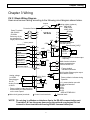
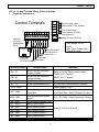
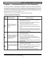
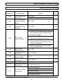
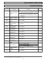
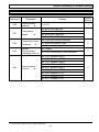
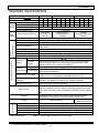
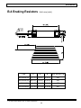
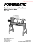
1
VFD-S
Variable Speed AC Motor Drive
230V/460V 0.25 HP – 3.0HP
0.2KW–2.2KW
High-performance / Low Noise / Mini-Type AC Drive
User Manual
April 24, 1999
DELTA ELECTRONICS, INC.
Delta Electronics, Inc.
NORTH / SOUTH AMERICA
EUROPE
DELTA PRODUCTS CORPORATION
DELTA ELECTRONICS GmbH
Sales Office
Sales Office
P.O.BOX 12173
HANNS-MARTIN-SCHLEYER-STRASSE 9D
5101 DAVIS DRIVE
GEWERBEPARK MUENCHHIEDE II
RESEARCH TRIANGLE PARK,
47877 WILLICH, GERMANY
NORTH CAROLINA, 27709 U. S. A.
PHONE: 49-2154-489-8888
PHONE: 1-919-767-3800
FAX: 49-2154-489-8889
FAX: 1-919-767-3969
http://www.deltadrives.com
ASIA
DELTA ELECTRONICS, INC.
TAOYUAN Plant
31-1 SHIEN PAN ROAD
KUEI SAN INDUSTRIAL ZONE
333 TAOYUAN, TAIWAN R. O. C.
PHONE: 886-3-361-6301
FAX: 886-3-362-7267
http://www.delta.com.tw
5011201801
9904
Table of Contents
Preface
Thank you for choosing DELTA’s high-performance VFD-S Series. VFD-S Series are
manufactured by adopting high-quality components, material and incorporating the latest
microprocessor technology available.
& Getting Started
This manual will be helpful in the installation, parameter setting, troubleshooting, and daily
maintenance of the AC motor drives. To guarantee safe operation of the equipment, read the
following safety guidelines before connecting power to the AC motor drives. Keep this
operating manual handy and distribute to all users for reference.
!
WARNING
!
Always read this manual thoroughly before using VFD-S series AC Motor Drives.
!
DANGER! AC input power must be disconnected before any maintenance.
Do not
connect or disconnect wires and connectors while power is applied to the circuit.
Maintenance must be performed by qualified technicians.
!
CAUTION! There are highly sensitive MOS components on the printed circuit boards.
These components are especially sensitive to static electricity. To avoid damage to these
components, do not touch these components or the circuit boards with metal objects or
your bare hands.
!
DANGER! A charge may still remain in the DC-link capacitor with hazardous voltages
even if the power has been turned off. To avoid personal injury, do not remove the cover
of the AC drive until all “DISPLAY LED” lights on the digital keypad are off. Please note
that there are live components exposed within the AC drive. Do not touch these live parts.
!
CAUTION! Ground the VFD-S using the ground terminal. The grounding method must
comply with the laws of the country where the AC drive is to be installed. Refer to Basic
Wiring Diagram (CH 3-1).
!
DANGER! The AC drive may be destroyed beyond repair if incorrect cables are
connected to the input/output terminals. Never connect the AC drive output terminals U,
V, and W directly to the AC main circuit power supply.
CAUTION! Heat sink may heat up over 70
the heat sink.
© 1999 DELTA ELECTRONICS, INC. ALL RIGHTS RESERVED
i
(158 ), during the operation. Do not touch
Table of Contents
CHAPTER 1: RECEIVING AND INSPECTIONS
1-1 Nameplate Information ………….…………………….………………………………...…….1
1-2 Model Explanation ………………………………….………………………………………….1
1-3 Serial Number Explanation …….………………………………….………………………….1
CHAPTER 2: STORAGE AND INSTALLATION
2-1 Storage ………………………………………….………………………………………………2
2-2 Ambient Conditions …………...……….………………..……………………………………..2
2-3 Installation ……………………….…….………………………………………………………..3
2-4 Connection …………………………….………………………………………………………..3
2-5 Environment ……………………….….………………………………………………………..5
2-6 Installation Steps ……………….…….………………………………………………………..6
CHAPTER 3: WIRING
3-1 Basic Wiring Diagram……………………………….……………………………….…………9
3-2 External Wiring ………………………………………………………………………………..10
3-3 Main Circuit Wiring…………………….……………………….………………..……………12
3-4 Control Terminal Wiring………….……………….…….…………………………………….13
3-5 Wiring Notes……….……………….……………………….…………………………………14
3-6 Motor Operation Precautions …………………………….……...……………………...…15
CHAPTER 4: DIGITAL KEYPAD OPERATION
4-1 Description of Digital Keypad……………………………………….…………………..……16
4-2 Explanation of Displayed Messages…………………...……………………………………17
4-3 Explanation of LED Indicators…………………………….……………………..…………18
4-4 Keypad Operation…………………………………....……………………………….………20
CHAPTER 5: DESCRIPTION OF PARAMETER SETTINGS
5-1 Group 0: User Parameters ………..………………………………………………………...22
5-2 Group 1: Basic Parameters ……………………………………………………….…………26
5-3 Group 2: Operating Method Parameters ……………...……….…………………………. 34
© 1999 DELTA ELECTRONICS, INC. ALL RIGHTS RESERVED
ii
Table of Contents
5-4 Group 3: Output Function Parameters ……………..…………………………..………....38
5-5 Group 4: Input Function Parameters ……………...……………...…….…………….…...43
5-6 Group 5: Multi-Step Speed and PLC (Process Logic Control) Parameters……….….59
5-7 Group 6: Protection Parameters …………………………………………………...…..…67
5-8 Group 7: Motor Parameters …………………………………………………………….....72
5-9 Group 8: Special Parameters ………………………..……………....…………………….74
5-10 Group 9: Communication Parameters …………………..…..……………………..…...80
CHAPTER 6: MAINTENANCE AND INSPECTIONS
6-1 Periodic Inspection ……………………..……………………….……………………….…..98
6-2 Periodic Maintenance…………………………………………………...…….…………….. 99
CHAPTER 7: TROUBLESHOOTING AND FAULT INFORMATION …….……………………100
CHAPTER 8: SUMMARY OF PARAMETER SETTINGS…………………………………………104
APPENDIX
APPENDIX A STANDARD SPECIFICATIONS ………….……………….…………………… 114
APPENDIX B ACCESSORIES LIST…………….………..………………...…………………...115
B-1 Din Rails ………………….…………………………...…………………….………...…..116
B-2 Remote Control Box ……….…………………..………………………………………….118
B-3 Control Bracket …………………………………………………………………………….119
B-4 Braking Resistors ………………..…………………………….…….…...………………121
B-5 EMI Filters ……………………….…………………………….…….……...…………….123
APPENDIX C VFD-S DIMENSIONS
……………………………....……………….……..……..126
APPENDIX D EC DECLARATION OF CONFORMITY………….…………………………….128
APPENDIX E WARRANTY….…………………………..……….………………………….……130
INDEX….…………….………..……….…………………………………………………..…….…….131
© 1999 DELTA ELECTRONICS, INC. ALL RIGHTS RESERVED
iii
Chapter 1 Receiving and Inspection
Chapter 1 Receiving and Inspection
This VFD-S AC drive has gone through rigorous quality control tests at the factory before
shipment. After receiving the AC motor drive, please check for the following:
Receiving
ü Check to make sure that the package includes an AC drive, the User Manual, and rubber
bushings.
ü Inspect the unit to insure it was not damaged during shipment.
ü Make sure that the part number indicated on the nameplate corresponds with the part
number of your order.
CH 1-1 Nameplate Information: *Example for 1HP 230V AC drive
AC Drive Model
Input Spec.
Output Spec.
Output Frequency Range
Serial NO. & Bar Code
MODEL
INPUT
OUTPUT
:
:
:
VFD007S23A
AC 3PH 200-230V 50/60Hz
1.6KVA 4.2A
Frequency Range: 1-400Hz
007S23A0T948007
DELTA ELECTRONICS INC.
MADE IN TAIWAN
CH 1-2 Model Explanation:
VFD 007 S 23 A
Version Type
Series name
Input Voltage
11: Single phase 115V
23 :Three phase 230V
43: Three phase 460 V
S Series
Applicable motor capacity
002 : 0.2KW 015 : 1.5KW
004 : 0.4KW 022 : 2.2KW
007 : 0.7KW
CH 1-3 Series Number Explanation:
If there is any nameplate information not
corresponding to your purchase order ot
any problem, please contact your supplier.
© 1999 DELTA ELECTRONICS, INC. ALL RIGHTS RESERVED
1
Chapter 1 Receiving and Inspection
T 9 01 001
Production number
Production week
Production year 1999
Production factory
(Taoyuan)
T 9 01 001
Production number
Production week
Production year 1999
Production factory
(Taoyuan)
© 1999 DELTA ELECTRONICS, INC. ALL RIGHTS RESERVED
2
Chapter 2 Storage and Installation
Chapter 2 Storage and Installations
CH 2-1 Storage
The AC motor drive should be kept in the shipping carton before installation. In
order to retain the warranty coverage, the AC motor drives should be stored
properly when it is not to be used for an extended period of time.
CH 2-2 Ambient Conditions:
w
Operation
w Storage
Air Temperature: -10o C to +40o C (14o F to 122o F)
Atmosphere pressure: 86 to 106 kPa
Installation Site Altitude: below 1000m
Vibration: Maximum 9.86 m/s2 (1G) at less than 20Hz
Maximum 5.88 m/s2 (1G) at 20Hz to 50Hz
Temperature: -20o C to + 60o C (-4o F to 140o F)
Relative Humidity: Less than 90%, no condensation allowed
Atmosphere pressure: 86 to 106 kPa
w TransportationTemperature: -20o C to +60o C (-4o F to 140o F)
Relative Humidity: Less than 90%, no condensation allowed
Atmosphere pressure: 86 to 106 kPa
Vibration: Maximum 9.86 m/s2 (1G) at less than 20Hz
Maximum 5.88 m/s2 (1G) at 20Hz to 50Hz
© 1999 DELTA ELECTRONICS, INC. ALL RIGHTS RESERVED
2
Chapter 2 Storage and Installation
CH 2-3 Installation:
CAUTION
The control, power supply and motor leads must be laid
separately. They must not be fed through the same cable
conduit / trunking.
High voltage insulation test equipment must not be used on
cables connected to the drive.
Improper installation of the AC drive will greatly reduce its life. Be sure to observe
the following precautions when selecting a mounting location. Failure to observe
these precautions may void the warranty!
w Do not mount the AC drive near heat-radiating elements or in direct sunlight.
w Do not install the AC drive in a place subjected to high temperature, high
humidity, excessive vibration, corrosive gases or liquids, or airborne dust or
metallic particles.
w Mount the AC drive vertically and do not restrict the air flow to the heat sink fins.
w The AC drive generates heat. Allow sufficient space around the unit for heat
dissipation as shown in the figure shown next page:
© 1999 DELTA ELECTRONICS, INC. ALL RIGHTS RESERVED
3
Chapter 2 Storage and Installation
Air Flow
150mm (6 inches)
or more
50mm
(2 inches)
or more
50mm
(2 inches)
or more
VFD-S
150mm (6 inches)
or more
Minimum Clearances and Air Flow
© 1999 DELTA ELECTRONICS, INC. ALL RIGHTS RESERVED
4
Chapter 2 Storage and Installation
CH 2-4 Connections:
DANGER
Hazardous Voltage
Before servicing the electrical system:
w Disconnect all power.
w Wait one minute until DC bus capacitors discharge.
Failure to observe this instruction will result in death or
serious injury.
& General Wiring Information
Applicable Codes
All VFD-S AC drives are Underwriters Laboratories, Inc. (UL) and Canadian
Underwriters Laboratories (cUL) listed, and therefore comply with the requirements
of the National Electrical Code (NEC) and the Canadian Electrical Code (CEC).
Installations intended to meet UL and cUL requirements must follow the instructions
provided in “CH 3-5 Wiring Notes” section below as a minimum standard. Where
local codes exceed these requirements, they must also be followed. Refer to the
technical data label affixed to the AC drive and the motor nameplate for electrical
data.
© 1999 DELTA ELECTRONICS, INC. ALL RIGHTS RESERVED
5
Chapter 2 Storage and Installation
CH 2-5 Environment
Avoid rain and moisture;
Avoid direct sunlight;
Avoid corrosive gases or liquids;
Free from airborne dust or metallic particles;
Free from vibration
Free from magnetic interference
Environment temperature : -10 to 50
Environment humidity: below 90% RH
Environment air pressure: 86 kpa to 106 kpa
CH 2-6 Installation Steps
KNOB
Component Explanation
1 Plastic Cover
2 Knob
3 Case
4 Aluminum Heat Sink
COVER
CASE
HEAT SINK
SCREW
DIVISION
PLATE
Installation Steps
1. Remove front cover screw and open.
2. Remove Division Plate.
If using optional conduit bracket,
please refer to next page.
3. Connect AC Input Power and motor
leads. Never connect the AC drive
output terminals U, V, W to main AC
Input power.
4. Reinstall Division Plate.
© 1999 DELTA ELECTRONICS, INC. ALL RIGHTS RESERVED
6
Chapter 2 Storage and Installation
SCREW
SCREW
For Optional Conduit Bracket:
Make sure to fasten both screws on
Install Conduit
Plateinasthe
shown.
conduit
bracketBracket
as shown
drawing for safety grounding purpose.
Bring all the wires out through the
conduit bracket.
Screw Torque: 5 to 6 kgf.cm
CONDUIT
BRACKET
SCREW
DIVISION
PLATE
Reinstall Division Plate.
Screw Torque: 5 to 6 kgf.cm
CONDIUT
BRACKET
SCREW
SCREW
Install Conduit Bracket cover and
tighten screws.
© 1999 DELTA ELECTRONICS, INC. ALL RIGHTS RESERVED
7
Chapter 2 Storage and Installation
UL ENCLOSED TYPE
SCREW
Close the cover and tighten screw as
shown. Screw torque: 5 to 6 kgf-cm
RS485
RJ11
JACK
RJ11
PLUG
© 1999 DELTA ELECTRONICS, INC. ALL RIGHTS RESERVED
8
For additional communication:
Plug the communication device
into the RJ11 jack for serial
communication.
Chapter 3 Wiring
Chapter 3 Wiring
CH 3-1 Basic Wiring Diagram
Users must connect wiring according to the following circuit diagram shown below.
Jumper
Protective Device
R
200-230VAC
50/ 60Hz
S
Select any of the
T
two terminals for
single phase models
P2/B1
P
1
Power Terminals
R
V
IM
W
+18V
Factory default
¡¹
CPU
2.4K£[
47K£[ AFM
M0
+18V
CPU
11V
M1
4.7K£[
Reset
U
T
Forward/Stop
Reverse/Stop
B2
VFD-S
S
Braking resistor (optional)
selec 80£[ 120W
200£[ 120W
t
400 £[ 120W
AC Motor
Anolog
+
Output DC 0
to + 10V -
47K£[
M2
Multi-step 1
Multi-step 2
GND
M3
CPU
M4
M5 4.7
RA
RB
K £[
MO1
+10V 10mA
(MAX)
3
Pot.
2
1
Analog Current
4~20mA
Factory default: output freq.(Pot)
¡¹
determined by the Potentiometer
on the control panel.
Main circuit (power) terminals
AVI
2
Multi-function indication
output contacts below
120VAC/28VDC 5A
RC ¡¹
Factory default:
indicates malfunction
GND
Anolog voltage
0~10VDC
Potentiometer
3K~5K £[
¡¹
Factory default: indicate output
frequency
+18V
Multi-step 3
Common signal
Grounding resistance
less than 100 £[
Potentiometer¡]1K£[¡^
Factory default: indicates during
¡¹
1
3
250£[
Multi-function Photocoupler output
below 48VDC 50mA
MCM
47K£[
GND
6
AC MOTOR DRIVES
Control circuit terminals
1
operation
RJ-11 communication port with
RS-485 serial interface
2:GND
3:SG4:SG+
5:+5V
* SEE NOTE BELOW *
Shielded leads
*NOTE*: Do not plug in a Modem or telephone line to the RS-485 communication port.
Terminals 2 & 5 are the power sources for the optional copy keypad. Do not
connect to these terminals while using RS-485 communication port.
© 1999 DELTA ELECTRONICS, INC. ALL RIGHTS RESERVED
9
Chapter 3 Wiring
CH 3-2 External Wiring
Item
Power
supply
FUSE or
NFB
Magnetic
contactor
(Optional)
AC
Reactor
(Optional)
EMI filter
(Optional)
DC Link
Reactor
(Optional)
Braking
Resistor
(Optional)
© 1999 DELTA ELECTRONICS, INC. ALL RIGHTS RESERVED
10
Explanation
Please follow the specific power supply
requirement shown in APPENDIX-A.
There may be inrush current during
power up. Please select the correct
fuse with rated current from the chart on
next page.
Please do not use a Magnetic contactor
as the I/O switch of the AC drive, this
will reduce the operating life cycle of
the AC drive.
In order to improve the power factor. An
AC Reactor may be necessary when
capacity is above 1000kVA, and the
wiring distance is within 10m.
To reduce the electromagnetic
interference.
Please refer to Appendix B for detailed
information on EMI filters
Please wire to manufacturer’s
specification to avoid damage to the AC
drive.
Used to reduce stopping time of the
motor. Select MVR200W120 or
MVR200W200, depending on the
application.
Chapter 3 Wiring
Fuse and No Fuse Breaker (NFB) Specifications
Models
VFD002S21A
VFD004S21A
VFD007S43A
VFD015S21A
VFD015S43A
VFD022S23A
VFD022S43A
VFD004S21A
VFD004S23A
VFD007S21A
VFD007S23A
VFD015S21A
VFD015M23A
Fuse for Branch circuit and short circuit protection
No Fuse
Voltage Ampere
Breaker
Manufacturer
P/N
rating
rating Class
Specifications
(VAC)
(A)
10A
Bussmann
JJN-10
300
10
T
20A
Bussmann
JJN-20
300
20
T
5A
Bussmann
JJS-10
600
10
T
30A
Bussmann
JJN-25
300
25
T
10A
Bussmann
JJS-15
600
15
T
20A
Bussmann
JJN-40
300
40
T
15A
Bussmann
JJS-20
600
20
T
10A
Bussmann
JJN-10
300
10
T
5A
Bussmann
JJN-10
300
10
T
20A
Bussmann
JJN-20
300
20
T
10A
Bussmann
JJN-20
300
20
T
30A
Bussmann
JJN-25
300
25
T
15A
Bussmann
JJN-25
300
25
T
© 1999 DELTA ELECTRONICS, INC. ALL RIGHTS RESERVED
11
Chapter 3 Wiring
CH 3-3 Main Circuit Wiring
1.
Wire Gauge: 12-18
AWG
Wire Type: Copper Only
Torque: 12 kg-cm
Main Circuit Terminals
Power Terminal
AC Input Line
Terminal
Power Terminals
115V Model
Motor
Connection
AC Input Line
Terminal
RS T U V W
L NU V W
B2 B P P1
1
Ground
Braking
Resistor
Motor
Connection
2
B2 B1
DC Reactor
Ground
Braking Resistor
2. Terminal Explanations
Terminal Symbol
Explanation of Terminal Function
R, S, T
AC line input terminals
L, N
AC line input terminals (115 VAC)
U, V, W
Motor connections
B1 / P2, B2
Connections for Braking Resistor(optional)
B1 / P2, P1
Connections for DC Link Reactor (optional)
Earth Ground
3. Terminal Dimensions
Model VFD-
002S11A, 002S21A, 002S23A,
004S11A, 004S21A, 004S23A
007S23A, 007S23A
Terminal
Specification
(Terminal φ)
M3.5
015S21A, 022S23A, 007S11A
015S33A, 022S43A 007S43A
015S43A, 004S43A,
M4
© 1999 DELTA ELECTRONICS, INC. ALL RIGHTS RESERVED
12
Chapter 3 Wiring
CH 3-4 Control Terminal Wiring (Factory Setting)
1. Terminal Explanations:
RA
RB
RC
MO1
MCM
Control Terminals
+10V
AVI AFM M0 M1 M2 M3 M4 M5 GND
RJ11
Operation
freq. set by
potentiometer
3K~5K
Mulit-step speed 3
Mulit-step speed 2
Mulit-step speed 1
Reset
Freq. meter
Reverse/Stop
0~10 VDC
Forward/Stop
Full scale voltmeter
RA - RC
RB – RC
MO1 -MCM
RJ - 11
+10V - GND
AVI - GND
AFM - GND
M0 - GND
M1 - GND
M2 - GND
M3 - GND
M4 - GND
M5 - GND
Photo coupler output
Factory setting : AC Motor
drive operational
RS485 Communication port
6~1
bias
potentolmeter: 1K
Terminal symbols
Relay contactor output
Factory setting : Fault indication
Terminal name
Wire Gauge: 22-24
AWG
Wire Type: Copper Only
Torque: 4 kg-cm
Remarks
Multi-Function Indication
Output Contact
Multi-Function Indication
Output Contact
Multi-function PHC output
Serial communication port
Analog voltage/current freq.
command
Analog frequency/current
meter
Multi-function auxiliary input
Multi-function input 1
Multi-function input 2
Multi-function input 3
Multi-function input 4
Multi-function input 5
© 1999 DELTA ELECTRONICS, INC. ALL RIGHTS RESERVED
13
Refer to Pr.3-06 Relay output contact
RA-RC (N.O. Contact)
RB-RC (N.C. Contact)
Refer to Pr.3-05
RS-485 serial communication interface
Power Supply (+10 V)
0 to +10 V (Max. Output Frequency) Input or
4 to 20mA (Max. Output Frequency) Input
0 to +10 V (Max. output Frequency) Output
Refer to Pr.4-04 to Pr.4-08
Chapter 3 Wiring
Note: Use twisted-shielded, twisted-pair or shielded-lead wires for the control signal wiring. It
is recommended to run all signal wiring in a separate steel conduit. The shield wire
should only be connected at the drive. Do not connect shield wire on both ends.
CH 3-5 Wiring Notes:
1.
2.
!
CAUTION: Do not connect the AC input to any of the U, V, W terminals, as it will
damage the AC drive.
!
WARNING: Ensure all screws are tightened to the proper torque rating.
3. During installation, follow all local electrical, construction, and safety codes for the country
the drive is to be installed in.
4. Ensure that the appropriate protective devices (circuit breaker or fuses) are connected
between the power supply and AC drive.
5. Make sure that the leads are connected correctly and the AC drive is properly grounded.
(Ground resistance should not exceed 100 . For 460V-class AC drive, the ground
resistance should not exceed 10 .)
6. Use ground leads that comply with AWG/MCM standards and keep them as short as
possible.
7. Multiple VFD-S units can be installed in one location. All the units should be grounded
directly to a common ground terminal. The VFD-S ground terminals may also be connected
in parallel, as shown in the figure below. Ensure there are no ground loops.
Forward
running
8. When the AC drive output terminals U, V, and W are connected to the motor terminals U, V,
and W, respectively, the motor will rotate counterclockwise (as viewed from the shaft ends
of the motor) when a forward operation command is received. To reverse the direction of
motor rotation, switch over any of the two motor leads.
9. Make sure that the power source is capable of supplying the correct voltage and required
current to the AC drive.
© 1999 DELTA ELECTRONICS, INC. ALL RIGHTS RESERVED
14
Chapter 3 Wiring
10. Do not attach or remove wiring when power is applied to the AC drive.
11. Do not monitor the signals on the circuit board while the AC drive is in operation.
12. For the single-phase applications, the AC input line can be connected to any two of the
three input terminals R, S, T. Note: This drive is not intended for the use with singlephase motors.
13. Route the wires of Power Terminals and Control Terminals separately, or 90°angle to each
other.
14. If a filter is required for reducing EMI (Electro Magnetic Interference), install it as close as
possible to AC drive. EMI can also be reduced by lowering the Carrier Frequency.
15. If the AC drive is installed in the place where load reactor is needed, install the filter close
to U.V.W. side of AC drive. Do not use a Capacitor or L-C Filter (Inductance-Capacitance)
or R-C Filter (Resistance-Capacitance).
16. When using a GFCI (Ground Fault Circuit Interrupt), select current sensor with not less than
200mA, with not less than 0.1-second detection to avoid nuisance tripping
CH 3-6 Motor Operation Precautions
1. When using the AC drive to operate a standard 3-phase induction motor, notice that the
energy loss is greater than an inverter duty motor.
2. While using the standard induction motor at low speed, the temperature of the motor may
rise, so do not operate the motor at low speed for a long period of time.
3. When the standard motor operates at low speed, the motor output torque will decrease,
please decrease the load during the operation.
4. If 100% output torque were desired at low speed operation, it may be necessary to use a
special motor that can handle this load (inverter duty).
© 1999 DELTA ELECTRONICS, INC. ALL RIGHTS RESERVED
15
Chapter 4 Digital Keypad Operation
Chapter 4 Digital Keypad Operation
CH 4-1 Description of Digital Keypad
This digital keypad includes two parts: Display panel and keypad. Display panel
provides the parameter display and shows operation status of the AC drive. Keypad
provides programming interface between users and AC drives.
LED Indication
Light during RUN, STOP,
FWD, and REV operation
RUN
FWD
REV
Potentiometer for
Frequency Setting.
Could be the Master
Frequency input by
setting Pr.2-00.
MIN.
Mode Key
Change between
different display modes.
MAX.
STOP
RUN
STOP/RESET
PROG
DATA
MODE
LED Display
Indicate frequency, motor
parameter setting value and
alarm contents.
RUN key
Start inverter drive operation.
STOP/RESET key
Stop inverter drive operation
and reset the inverter after
faults occurred.
PROG/DATA key
Set the different parameters
and enter information.
UP and DOWN key
Sets the parameter number
or changes the numerical
data such as the freq.
reference.
MODE
PROG/DATA
RUN
Mode
By pressing the “mode” key repetitively, the display will show status at
the AC drive such as the reference frequency, output frequency, and
output current.
PROG/DATA
Pressing the “PROG/DATA” key will store entered data or can show
factory stored data.
Run
Start the AC drive operation. This key has no function when the drive is
controlled by the External Control Terminals.
© 1999 DELTA ELECTRONICS, INC. ALL RIGHTS RESERVED
16
Chapter 4 Digital Keypad Operation
STOP/RESET
Stop / Reset
Stop AC drive operation. If the drive stops due to a fault, correct the fault
first, then press this key to reset the drive.
Up / Down
Press the “Up” or “Down” keys momentarily to change parameter settings.
These keys may also be used to scroll through different operating values
or parameters. Pressing the “Up” or “Down” key momentarily, will change
the parameter settings in single-unit increments. To quickly run through
the range of settings, press down and hold the key.
CH 4-2 Explanations of Display Messages
Display
Message
Descriptions
Displays the AC drive Master Frequency.
Displays the Actual Operation Frequency present at
terminals U, V, and W.
Displays the output current present at terminals U, V, and W
Displays the custom unit (u), where u = H x Pr 0-05.
Displays the counter value (C).
Displays the internal PLC process step currently being
performed.
Indicates the DC−BUS voltage
Indicates the output voltage
Displays the specified parameter group
© 1999 DELTA ELECTRONICS, INC. ALL RIGHTS RESERVED
17
Chapter 4 Digital Keypad Operation
Displays the specified parameter.
Displays the actual value stored within the specified
parameter.
Displays AC drive forward run status.
Displays AC drive reverse run status.
Displays “End” for approximately 0.5 second if input has been
accepted. After a parameter value has been set, the new
value is automatically stored in memory. To modify an entry,
use the
and
keys.
Displays “Err”, if the input is invalid.
CH 4-3 Explanation of LED Indicators
STOP LED lights when STOP botton
has been pressed.
RUN LED lights during RUN
operation
RUN
FWD
REV
FWD LED lights during
forward operation
REV LED lights during
reverse operation
© 1999 DELTA ELECTRONICS, INC. ALL RIGHTS RESERVED
18
STOP
Chapter 4 Digital Keypad Operation
1. Description of LED functions of RUN and STOP
Output frequency
of the AC motor
drive
STOP
/RESET KEY
RUN
STOP/
RESET KEY
KEY
Frequency
command
RUN
Indication
STOP
Indication
Light
Dark
Flash
2. Description of LED functions of FWD and REV.
Output frequency
of the AC drive
FWD
REV
RUN
FWD
REV
FWD
Indication
REV
Indication
Light
Flash
© 1999 DELTA ELECTRONICS, INC. ALL RIGHTS RESERVED
19
Dark
Chapter 4 Digital Keypad Operation
CH 4-4 Keypad Operation
change display
mode
MODE
set freq.
set freq.
set freq.
MODE
F60.0
change
display mode
H60.0
A 4.2
change
display mode
display freq.
command
CEXX
communication error, only
appears when communication
error happens.
FWD
MODE
U60.0
change
display mode
PROG
DATA
MODE
MODE
set freq.
MODE
display
parameter
group
0-
display
parameter
number
set
parameter
group
PROG
DATA
0-00
set
parameter
number
PROG
DATA
display data of
the parameter
PROG
DATA
MODE
d 0
display
parameter
number
store data
set
parameter
data
Err
parameter is locked or data is out of range, or
data can't be entered during RUN mode.
End
data is stored
© 1999 DELTA ELECTRONICS, INC. ALL RIGHTS RESERVED
20
change display
mode
change
operation
direction
REV
REV state can't
attain if reverse is
inhibited
Chapter 5 Description of Parameter Settings
Chapter 5 Description of Parameter Settings
This chapter will explain all parameters in detail. They are divided into ten
parameter groups to categorize parameter settings more clearly and effectively.
The ten-parameter groups are described as below:
Group 0: User Parameters
Group 1: Basic Parameters
Group 2: Operating Method Parameters
Group 3: Output Function Parameters
Group 4: Input Function Parameters
Group 5: Multi-step Speed and PLC (Process Logic Control) Parameters
Group 6: Protection Parameters
Group 7: Motor Parameters
Group 8: Special Parameters
Group 9: Communication Parameters
© 1999 DELTA ELECTRONICS, INC. ALL RIGHTS RESERVED
21
Chapter 5 Description of Parameter Settings
CH 5-1 Group 0: User Parameters
0 - 00 Identity Code of AC Motor Drive
Settings None
V \ HP
115V/230V
460V
1/4
d0
-- -- --
1/2
d2
d3
Factory setting: d #
1
d4
d5
2
d6
d7
3
d8
d9
& This parameter shows the capacity of the AC drive. Users can read Pr.0-01 to
check if it is the rated current of the AC drive corresponds to the identity code
shown above and the current shown below.
V \ HP
115V/230V
460V
0 - 01
1/4
1.6A
-- -- --
1/2
2.5A
1.5 A
1
4.2A
2.5 A
Rated Current Display of the AC drive
Settings
None
2
7.5A
4.2 A
3
11.0A
5.5 A
Factory Setting: d ##.#
Unit: 0.1A
& This parameter displays the rated current of the AC drive. It will display based
on Pr.0-00, and is read-only.
0 - 02
Parameter Reset
Settings
Factory Setting: d 0
d 0 to d 9 Not used
d 10 All parameters are reset to be factory settings
& This setting allows the user to return all parameters to the factory default
settings.
© 1999 DELTA ELECTRONICS, INC. ALL RIGHTS RESERVED
22
Chapter 5 Description of Parameter Settings
0 - 03
Start-up Display Selection
Settings
d0
Factory Setting: d 0
Display the Master Frequency (F)
d1
d2
Display the actual operation frequency (H)
Display the content of users-defined unit
d 3 Display the output current (A
This parameter can be set during operation.
0 - 04
Content of User Defined Unit
Settings
d0
Factory Setting: d 0
Display the user-defined unit (u)
d1
d2
Display the counter value (C)
Display the content of PLC time (1 – tt)
d3
d4
Display the DC BUS voltage (U)
Display the output voltage (E)
This parameter can be set during operation.
0-05
Note: Display the user-defined unit, where unit = H H
0 - 05
User Defined Coefficient K
Settings
Factory Setting: d 1.0
d 0.1 to d 160
Unit: 0.1
This parameter can be set during operation.
& The coefficient K determines the multiplying factor for the user-defined unit.
The display value is calculated as follows:
Display value =(output frequency*K)
& The display window is only capable of showing three digits, yet you could use
Pr.0-05 to create larger numbers. The display windows uses decimal points
to signify numbers up to five digits as illustrated in the next page:
© 1999 DELTA ELECTRONICS, INC. ALL RIGHTS RESERVED
23
Chapter 5 Description of Parameter Settings
Display
999
0 - 06
Number Represented
The absence of a decimal point indicates a three –digit integer.
99.9
A signal decimal point between the middle and the right-most
numbers is a true decimal point; it separates ones and tenths as
in “30.5” (thirty and one-half).
999.
A single decimal point after the fight-most numbers is not a true
decimal point; instead it indicates that a zero follows the rightmost number. For example, the number 1230 would be display
as “123.”
99.9.
Two decimal points (one between the middle and the right-most
numbers, and one after the right-most number) are not true
decimal points; instead they indicate that two zeros follow the
right-most number. For example, the number 34500 would be
display as “34.5.”.
Software Version
Setting
Factory Setting: d #.#
None
& The software version is read-only that stores the version number of VFD-S
series software.
0 - 07
Password Input
Settings
Factory Setting: d 0
d 0 to d 999
Unit: 1
& Pr.0-07 and Pr.0-08 work together to provide data security for the AC drive.
When Pr.0-08 is set to a value other than 0, a password must be entered to
alter the values of parameters. The password is the number set in Pr.0-08,
which ranges from 1 to 999. Pr.0-07 is where the password is entered to
allow parameter values to be altered.
© 1999 DELTA ELECTRONICS, INC. ALL RIGHTS RESERVED
24
Chapter 5 Description of Parameter Settings
& Display states:
d 0: no password / correct password has been input.
d 1: parameters are locked.
0 - 08
Password Configuration
Settings
Factory Setting: d 0
d 0 to d 999
Unit: 1
& For a password to be configured, the non-zero value assigned to Pr.0-08 must
be entered twice. In other words, set the value of Pr.0-08 to the desired
value and press the Prog/Data key. Then, press the Prog/Data key again to
display the value of Pr.0-08. Finally, press the Prog/Data key again to store
the displayed value, which then becomes the password.
For example, say that pr.0-08 is set to 111. When the AC drive is poweredup, all the parameters will be locked and their values cannot be changed. To
permit the values of parameters to be altered, navigate to Pr.0-07 and change
its value to 111 (the password configured in Pr.0-08). Then press the
Prog/Data key, and you may alter the parameter values.
& Display states:
d 0: no password
d 1: password has been set
© 1999 DELTA ELECTRONICS, INC. ALL RIGHTS RESERVED
25
Chapter 5 Description of Parameter Settings
CH 5-2 Group 1: Basic Parameters
1 – 00
Maximum Output Frequency (Fo. max)
Settings
&
Unit: 0.1Hz
This parameter determines the AC drive’s Maximum Output Frequency. All
the AC drive analog inputs (0 to +10V, 4 to 20mA) are scaled to correspond
to the output frequency range.
1 - 01
Maximum Voltage Frequency
Settings
&
d 50.0 to d 400 Hz
Factory Setting: d 60.0
d 10.0 to d 400Hz
Unit: 0.1Hz
This value should be set according to rated frequency of the motor as
indicated on the motor nameplate. Maximum Voltage Frequency determines
the volts per hertz ratio. For example, if the drive is rated for 460 VAC output
and the Maximum Voltage Frequency is set to 60Hz, the drive will maintain a
constant ratio of 7.66 v/Hz. The setting value must be greater than or equal
to the middle freq. setting (Pr.1-03).
1 - 02
Max. Output Voltage (Vmax)
Factory Setting: d 220*
Settings d 2.0 to d 255V*
*Twice value for 460V class
&
Factory Setting: d 60.0
Unit: 0.1V*
This parameter determines the Maximum Output Voltage of the AC drive.
The Maximum Output Voltage setting must be smaller than or equal to the
rated voltage of the motor as indicated on the motor nameplate. The setting
value must be greater than or equal to the Mid-Point Voltage (Pr.1-04).
© 1999 DELTA ELECTRONICS, INC. ALL RIGHTS RESERVED
26
Chapter 5 Description of Parameter Settings
1 - 03
Mid-Point Frequency (Fmid)
Factory Setting: d 1.0
Settings d 1.0 to d 400Hz
&
Unit: 0.1Hz
This parameter sets the Mid-Point Frequency of V/F curve. With this setting,
the V/F ratio between Minimum Frequency and Mid-Point frequency can be
determined. This parameter must be greater than or equal to Minimum
Output Frequency (Pr.1-05) and equal to or less than Maximum Voltage
Frequency (Pr.1-01).
1 - 04
Mid-Point Voltage (Vmid)
Factory Setting: d12.0*
Settings d 2.0 to d 255V*
*Twice value for 460V class
Unit: 0.1V*
& The parameter sets the Mid-Point Voltage of any V/F curve. With this setting,
the V/F ratio between Minimum Frequency and Mid-Point Frequency can be
determined. This parameter must be equal to or greater than Minimum
Output Voltage (Pr.1-06) and equal to or less than Maximum Output Voltage
(Pr.1-02).
1 - 05
Minimum Output Frequency (Fmin)
Settings
d 1.0 to d 60.0Hz
Factory Setting: d 1.0
Unit: 0.1Hz
& This parameter sets the Minimum Output Frequency of the AC drive. This
parameter must be equal to or less than Mid-Point Frequency (Pr.1-03).
© 1999 DELTA ELECTRONICS, INC. ALL RIGHTS RESERVED
27
Chapter 5 Description of Parameter Settings
1 - 06 Minimum Output Voltage (Vmin)
Settings d 2.0 to d 255V*
*Twice value for 460V class
&
This parameter sets Minimum Output Voltage of the AC drive. This
parameter must be equal to or less than Mid-Point Voltage (Pr.1-04).
1 - 07
Upper Bound of Output Frequency
Settings
&
Factory Setting: d12.0*
Unit: 0.1V*
d 1 to d110%
Factory Setting: d 100
Unit: 1%
This parameter must be equal to or greater than the Lower Bound of Output
Frequency (Pr.1-08). The Maximum Output Frequency (Pr.1-00) is regarded
as 100%.
© 1999 DELTA ELECTRONICS, INC. ALL RIGHTS RESERVED
28
Chapter 5 Description of Parameter Settings
1 - 08
Lower Bound of Output Frequency
Settings
d 0 to d100%
Factory Setting: d 0
Unit: 1%
&
The Upper/Lower Bound is to prevent operation error and machine damage.
&
If the Upper Bound of Output Frequency is 50Hz and the Maximum Output
Frequency is 60Hz, the Maximum Output Frequency will be limited to 50Hz.
&
If the Lower Bound of Output Frequency is 10Hz, and the Minimum Output
Frequency
Pr.1-05 is set at 1.0Hz, then any Command Frequency
between 1-10Hz will generate a 10Hz output from the drive.
&
This parameter must be equal to or less than the Upper Bound of Output
Frequency (Pr.1-07).
1 - 09
1 - 10
1 - 11
1 - 12
Acceleration Time 1 (Taccel 1)
Deceleration Time 1 (Tdecel 1)
Acceleration Time 2 (Taccel 2)
Deceleration Time 2 (Tdecel 2)
Factory Setting : d10.0
Factory Setting : d10.0
Factory Setting : d10.0
Factory Setting : d10.0
Settings d 0.1 to d 600Sec
Unit: 0.1Sec
These parameters can be set during operation.
&
Pr.1-09. This parameter is used to determine the time required for the AC
drive to ramp from 0 Hz to its Maximum Output Frequency (Pr.1-00). The
rate is linear unless S-Curve is “Enabled.”
&
Pr.1-10. This parameter is used to determine the time required for the AC
drive to decelerate from the Maximum Output Frequency (Pr.1-00) down to 0
Hz. The rate is linear unless S-Curve is “Enabled.”
© 1999 DELTA ELECTRONICS, INC. ALL RIGHTS RESERVED
29
Chapter 5 Description of Parameter Settings
&
The accel/decel time 2 determines the time for the AC drive to accel/decel
from 0Hz to Maximum Output Frequency (Pr.1-00) (accel/decel time 1 is the
default). A Multi-Function Input terminals must be programmed to select
accel/decel time 2 and the terminals must be closed to select accel/decel
time 2. See Pr.4-04 to Pr.4-08.
&
In the diagram shown below, the accel/decel time of the AC drive is the time
between 0 Hz to Maximum Output Frequency (Pr.1-00). Suppose the
Maximum Output Frequency is 60 Hz, start-up frequency (1-05) is 1.0 Hz,
and accel/decel time is 10 seconds. The actual time for the AC drive to
accelerate from start-up to 60 Hz is 9.83 seconds and the deceleration time
is also 9.83 seconds.
1 - 13 Jog Accel/Decel Time
Factory Setting: d 10.0
Settings d 0.1 to d 600Sec
Unit: 0.1Sec
This parameter can be set during operation.
© 1999 DELTA ELECTRONICS, INC. ALL RIGHTS RESERVED
30
Chapter 5 Description of Parameter Settings
1 - 14
Jog Frequency
Settings
Factory Setting : d 6.0
d 1.0 to d 400Hz
Unit: 0.1Hz
This parameter can be set during operation.
&
The JOG function can be selected using Multi-function Input terminals (Pr.404 to Pr.4-08) if programmed for Jog (d10). When the Jog terminal is
“closed”, the AC drive will accelerate from Minimum Output
Frequency Pr.1-05
to Jog Frequency
Pr.1-14 . When the Jog
terminal “open”, the AC drive will decelerate from Jog Frequency to zero.
The accel/decel time is decided by the Jog accel/decel time Pr.1-13 .
During operation, the AC drive can not perform Jog command. And during
Jog operation, other operation commands can not be accepted, except
command of FORWARD, REVERSE and STOP keys on the digital keypad.
© 1999 DELTA ELECTRONICS, INC. ALL RIGHTS RESERVED
31
Chapter 5 Description of Parameter Settings
1 - 15 Auto-Acceleration / Deceleration
Factory Setting : d 0
Settings d 0 Linear acceleration / deceleration.
d1
d2
Auto acceleration, linear Deceleration.
Linear acceleration, auto Deceleration.
d3
d4
Auto acceleration / deceleration
Linear acceleration/deceleration, and stall prevention
during deceleration.
Auto acceleration, linear deceleration, and stall
prevention during deceleration
d5
&
If the auto accel/decel is selected, the AC drive will accel/ decel in the
fastest and smoothest means possible by automatically adjusting the time
of accel/decel.
1 - 16 Acceleration S-Curve
Settings d 0 to d 7
Factory Setting: d 0
1 - 17
Factory Setting: d 0
Deceleration S-Curve
Settings
d 0 to d 7
&
These two parameters allow you to configure whether the acceleration
and/or deceleration ramps are linear or S-shaped. The S-curve is enabled
when set at d1-d7. Setting d1 offers the quickest S-curve and d7 offers the
longest and smoothest S-curve. The AC drive will not follow the accel/decel
time in Pr.1-09 to Pr.1-12. To Disable the S-curve, set Pr.1-16 and Pr.1-17
to d0.
&
From the diagram shown below, the original setting accel/decel time will be
for reference when the function of the S-curve is enabled. The actual
accel/decel time will be determined based on the S-curve selected (d1 to
d7).
© 1999 DELTA ELECTRONICS, INC. ALL RIGHTS RESERVED
32
Chapter 5 Description of Parameter Settings
© 1999 DELTA ELECTRONICS, INC. ALL RIGHTS RESERVED
33
Current signal input (4-20mA)
Chapter 5 Description of Parameter Settings
CH 5-3 Group 2: Operation Method Parameters
2 – 00
Source of Frequency Command
Settings
Factory Setting: d 0
d 0 Master Frequency input determined by digital keypad.
d1
d2
d3
d4
Master Frequency determined by analog signal DC
0V-10V (external terminal AVI).
Master Frequency determined by analog signal DC
4mA - 20mA (external terminal AVI).
Master Frequency determined by Potentiometer on
the digital keypad.
Master Frequency operated by RS-485 serial
communication interface.
&
This parameter sets the Frequency Command Source of the AC drive.
If the Frequency Command Source is external (DC 0 to +10V or 4 to 20mA),
please make sure the AVI terminal jumper is in the proper position as
shown below.
&
Position of jumper: Please open the top cover. It is at the lower-left corner of
the panel. The jumper J1 determines the type of external analog input, either
DC voltage signal or current signal.
© 1999 DELTA ELECTRONICS, INC. ALL RIGHTS RESERVED
34
Chapter 5 Description of Parameter Settings
2 - 01
Source of Operation Command
Settings
d0
Controlled by the keypad
d1
d2
d3
d4
&
Factory Setting: d 0
Controlled by the external terminals, keypad STOP
enabled.
Controlled by the external terminals, keypad STOP
disabled.
Controlled by the RS-485 communication interface,
keypad STOP enabled.
Controlled by the RS-485 communication interface,
keypad STOP disabled.
When the AC drive is controlled by an external source, please refer to
parameter group 4 for detailed explanations on related parameter settings.
2 - 02
Stop Method
Settings
d0
Factory Setting: d 0
Ramp stop
d 1 Coast stop
&
The parameter determines how the motor is stopped when the AC drive
receives a valid stop command.
1.
Ramp: the AC drive decelerates the motor to Minimum Output Frequency
(Pr.1-05) and then stops according to the deceleration time set in Pr.1-10 or
Pr.1-12.
2.
Coast: the AC drive stops output instantly upon command, and the motor
free runs until it comes to a complete stop.
© 1999 DELTA ELECTRONICS, INC. ALL RIGHTS RESERVED
35
Chapter 5 Description of Parameter Settings
Note: The motor stop method is usually determined by the characteristics of the
motor load and frequency of stops.
2 - 03
PWM Carrier Frequency Selections
Settings
d 03 fc= 3KHz
d 04 fc= 4KHz
d 05 fc= 5KHz
Factory Setting: d 10
Unit: 1KHz
to
d 10 fc= 10KHz
This parameter can set the carrier frequency of PWM output.
Carrier
Frequency
3KHz
10KHz
Electromagnetic
Heat
Acoustic Noise Noise, Leakage
Dissipation
Current
Significant
Minimal
Minimal
Minimal
Significant
© 1999 DELTA ELECTRONICS, INC. ALL RIGHTS RESERVED
36
Significant
Chapter 5 Description of Parameter Settings
& From the above table, we see that the carrier frequency of PWM output has a
significant influence on the electromagnetic noise, heat dissipation of the AC
drive, and the acoustic noise to the motor.
2 - 04
Reverse Operation Inhibit
Settings d 0
Factory Setting: d 0
enable REV operation
d1
disable REV operation
& The parameter determines whether the AC drive can operate in the reverse
direction.
2 - 05
ACI Input Loss Detection
Settings d 0
d1
d2
Factory Setting: d 0
Upon the loss of ACI, the drive will default to an
output frequency of 0 Hz.
Upon the loss of ACI, the drive will stop and display
error message “EF”.
Upon the loss of ACI, the drive will continue to run at
the last known ACI input.
& This parameter is only effective when the Source of Frequency is commanded
by a 4 to 20 mA signal. The ACI input is considered lost when the ACI signal
falls below 2 mA.
© 1999 DELTA ELECTRONICS, INC. ALL RIGHTS RESERVED
37
Chapter 5 Description of Parameter Settings
CH 5-4 Group 3: Output Function Parameters
3 - 00
Analog Output Signal
Settings
d0
d1
Factory Setting: d 0
Analog frequency meter (0 to Maximum Output
Frequency).
Analog current meter (0 to 250% of the rated AC
drive current).
& This parameter selects either Output Frequency or current to be displayed
using the 0 to10V AFM output.
3 - 01
Analog Output Gain
Factory Setting: d100
Settings d 1 to d 200%
Unit: 1%
The parameter can be set during operation.
&
The parameter sets the voltage range of analog output signal (frequency or
current), on output terminal AFM.
The analog output voltage is directly proportional to the output frequency of the AC
drive. With the factory setting of 100%, the Maximum Output Frequency (Pr.1-00)
of the AC drive corresponds to +10VDC analog voltage output. (The actual voltage
is about +10VDC, and can be adjusted by Pr.3-01)
© 1999 DELTA ELECTRONICS, INC. ALL RIGHTS RESERVED
38
Chapter 5 Description of Parameter Settings
The analog output voltage is directly proportional to the output current of the AC
drive. With the factory setting of 100%, the 2.5 times rated current of the AC drive
corresponds to +10VDC analog voltage output. (The actual voltage is about
+10VDC, and can be adjusted by Pr. 3-01)
Note: Any type of voltmeter can be used. If the meter reads full scale at a voltage
less than 10 volts, then Pr.3-01 should be set by the following formula:
Pr.3-01 = ((meter full scale voltage)/10) ×100%
For Example: When using the meter with full scale of 5 volts, adjust Pr.3-01 to
50%
3 - 02
Desired Frequency Attained
Settings
&
Factory Setting: d 1.0
d 1.0 to d 400 Hz
Unit: 0.1Hz
If a Multi-function output terminal is set to function as Desired Frequency
Attained (Pr.3-05 or 3-06=d9), then the output will be activated when the
programmed frequency is attained.
© 1999 DELTA ELECTRONICS, INC. ALL RIGHTS RESERVED
39
Chapter 5 Description of Parameter Settings
3 - 03 Terminal Count Value
Settings d 0 to d 999
Factory Setting: d 0
& The parameter determines the value of the internal counter. The internal
counter can be triggered by the external terminal (Pr.4-4 to Pr.4-8, d19). Upon
completion of counting, the specified output terminal will be activated. (Pr.305, Pr.3-06, d14).
3 - 04
Preliminary Count Value
Settings
Factory Setting: d 0
d 0 to d 999
& When the counter value is counted up from “1” to the setting value of this
parameter, the corresponding multi-function output terminal will be closed,
when sets d15 as desired value attained setting. The application can be that
closing the multi-function output terminal makes the AC drive operate at low
speed until stop before the counting value is going to be attained.
The timing diagram is shown in the next page:
© 1999 DELTA ELECTRONICS, INC. ALL RIGHTS RESERVED
40
Chapter 5 Description of Parameter Settings
3 - 05
Multi-function Output Terminal 1
(Photocoupler output)
Factory Setting: d 1
3 - 06
Multi-function Output Terminal 2 (relay output)
Factory Setting: d 8
Settings
d 0 to d 15
Function Table List:
Setting
Function
Setting
Function
d 0 Not used
d 9 Desired Frequency Attained
d 1 AC Drive Operational
d 10 PLC Program Running
Maximum Output Frequency d 11 PLC Program Step Completed
d2
Attained
d 12 PLC Program Completed
d 3 Zero speed
d 13 PLC Operation Paused
d 4 Over-Torque detection
d 14 Terminal Count Value Attained
d 5 Base-Block (B.B.) Indication d 15 Preliminary Counter Value Attained
d 6 Low-Voltage Indication
d 16 All Functions Normal
d 7 AC Drive Operation Mode
d 8 Fault Indication
© 1999 DELTA ELECTRONICS, INC. ALL RIGHTS RESERVED
41
Chapter 5 Description of Parameter Settings
&
Function Explanations
d 0 Not Used.
d 1 AC drive operational: the output of output terminal will be activated when
there is an output from the drive.
d 2 Maximum Output Frequency Attained: the output will be activated when
the AC drive attains Maximum Output Frequency.
d 3 Zero speed: the output will be activated when Command Frequency is lower
than the Minimum Output Frequency.
d 4 Over-Torque Detection: the output will be activated as long as the overtorque is detected. Pr.6-04 determines the Over-Torque detection level.
d 5 Base-Block (B.B.) Indication: the output will be activated when the output of
the AC drive is shut off by external Baseblock.
d 6 Low Voltage Indication: the output will be activated when low voltage is
detected.
d 7 AC Drive Operation Mode: the output will be activated when the operation of
the AC drive is controlled by External Control Terminals.
d 8 Fault Indication: the output will be activated when faults occur (oc, ov, oH,
oL, oL1, EF, cF3, HPF, ocA, ocd, ocn, GF).
d 9 Desired Frequency Attained: the output will be activated when the desired
frequency (Pr.3-02)is attained.
d10 PLC Program Running: the output will be activated when the PLC program
is running.
d11 PLC Program Step Completed: the output will be activated for 0.5 sec.
when each multi-step speed is attained.
d12 PLC Program completed: the output will be activated for 0.5 sec. when the
PLC program cycle has completed.
d13 PLC Program Operation Paused: the output will be activated when PLC
operation is paused.
d14 Terminal Count Value Attained: counter reaches Terminal Count Value.
d15 Preliminary Count Value Attained: counter reaches Preliminary Count
Value.
d16 All Functions Normal: a When the AC Drive is in a normal state, the contact
will be closed. If there is a fault or the AC drive is not functioning normally,
the contact will be open.
© 1999 DELTA ELECTRONICS, INC. ALL RIGHTS RESERVED
42
Chapter 5 Description of Parameter Settings
CH 5-5 Group 4: Input Function Parameters
4 - 00
Potentiometer Bias Frequency
Settings
Factory Setting:
d0.0
Unit: 0.1Hz
d 0.0 to d 350Hz
This parameter can be set during the operation.
4 - 01
Potentiometer Bias Polarity
Settings
Factory Setting: d 0
d 0 Positive bias
d 1 Negative bias
This parameter can be set during the operation.
4 - 02
Potentiometer Frequency Gain
Factory Setting: d 100
Settings d 1 to d 200%
Unit: 1%
This parameter can be set during the operation.
4 - 03
Potentiometer Reverse Motion Enable
Settings
d0
Forward motion only
d1
&
Factory Setting: d 0
Reverse motion enable (must be negative bias)
Pr.4-00 to Pr.4-03 are used when the source of frequency command is the
analog signal (0 to +10V DC or 4 to 20 mA DC). Refer to the following
examples.
© 1999 DELTA ELECTRONICS, INC. ALL RIGHTS RESERVED
43
Pr.4-02=100%-- Pot. Freq. Gain
Chapter 5 Description of Parameter Settings
Example 1:
The following is the most common method. Set parameter 2-00 to d1 (0 to
+10V signal), d2 (4 to 20mA current signal), or d3 (keypad potentiometer).
© 1999 DELTA ELECTRONICS, INC. ALL RIGHTS RESERVED
44
Pr.4-02=100%--Pot.
Pr.4-02=83%-Pot.Freq.
Freq.Gain
Gain
Chapter 5 Description of Parameter Settings
Example 2:
In this example with the potentiometer set to 0V the Output Frequency is 10 Hz.
The mid-point of the potentiometer becomes 40 Hz. Once the Maximum Output
Frequency is reached any further increase of the potentiometer will not increase
output frequency.
Example 3:
The example also shows the popular method. The whole scale of the
potentiometer can be used as desired. In addition to signals of 0 to 10V and 4 to
20mA, the popular voltage signals also include signals of 0 to 5V, 20 to 4mA or
that under 10V. Regarding the setting, please refer to the following examples.
© 1999 DELTA ELECTRONICS, INC. ALL RIGHTS RESERVED
45
Pr.4-02=200%-Pr.4-01=1
Pr.4-02=100%---- Bias
Pot.
Polarity
Freq. Gain
Chapter 5 Description of Parameter Settings
Example 4:
This example shows a potentiometer range of 0 to 5 Volts.
Example 5:
In this example a 1 volt negative bias is used. In a noise environment, it is
advantageous to use negative bias to provide a noise margin (1V in this example).
© 1999 DELTA ELECTRONICS, INC. ALL RIGHTS RESERVED
46
Pr.4-00=6Hz--Potentiometer
Pr.4-01=1
--- Bias Polarity Bias Freq.
Chapter 5 Description of Parameter Settings
Example 6:
In this example, a negative bias is used to provide a noise margin. Also a
potentiometer frequency gain is used to allow the Maximum Output Frequency to
be reached.
Example 7:
In this example, the potentiometer is programmed to run a motor is both forward
and reverse direction. A motor will be idle when the potentiometer position is at
mid-point of its scale. Using Pr.4-03 will disable the external FWD and REV
controls.
© 1999 DELTA ELECTRONICS, INC. ALL RIGHTS RESERVED
47
Pr.4-01=1 --- Bias
Pr.4-02=100%-Pot.
Polarity
Freq. Gain
Chapter 5 Description of Parameter Settings
Example 8:
In this example, the option of anti-slope is shown. Anti-slope is used in an
application where control of pressure, temperature, or flow is needed. Under a
high pressure or flow situation, a sensor will generate a large signal such as 20
mA or 10V. With anti-slope enable, the large signal will slow or stop the AC drive
4 - 04
Multi-function Input Terminal (M0, M1)
Settings
4 – 05
4 – 06
4 – 07
4 – 08
d 0 to d 20
Multi-function Input Terminal (M2)
Multi-function Input Terminal (M3)
Multi-function Input Terminal (M4)
Multi-function Input Terminal (M5)
Settings
Factory Setting: d 1
d0, d 4 to d 20
© 1999 DELTA ELECTRONICS, INC. ALL RIGHTS RESERVED
48
Factory Setting: d 6
Factory Setting: d 7
Factory Setting: d 8
Factory Setting: d 9
Chapter 5 Description of Parameter Settings
Parameters & Functions table:
Value
Function
d 0 Parameter Disable
Value
Function
d11 Accel/Decel Speed Inhibit
d1
M0: FWD / STOP
M1: REV / STOP
d12
d2
M0: RUN / STOP
M1: FWD / REV
d13
d3
3-Wire Operation Control mode
(M0,M1,M2)
d14
d4
First or Second Accel/Decel
Time Selection
External Base Block (N.O.)
(Normally Open Contact Input)
External Base Block (N.C.)
(Normally Close Contact Input)
d15
Increase Master Frequency
d16
Decrease Master Frequency
d6
d7
d8
External Fault ( Normally Open)
External Fault ( Normally
Closed )
External Reset
Multi-Step Speed Command 1
Multi-Step Speed Command 2
d17
d18
d19
Run PLC Program
Pause PLC Program
Counter Trigger Signal
d9
Multi-Step Speed Command 3
d20
Counter Reset
d10
Jog operation
d21
ACI / AVI Selection
d5
Explanations:
d0 Parameter Disable:
Enter value (d0) to disable any Multi-Function Input Terminal: M1 (Pr.4-04), M2
(Pr.4-05), M3 (Pr.4-06), M4 (Pr.4-07) or M5 (Pr.4-08)
Note: The purpose of this function is to provide isolation for unused Multi-Function
Input Terminals. Any unused terminals should be programmed to d0 to insure
they have no effect on drive operation.
© 1999 DELTA ELECTRONICS, INC. ALL RIGHTS RESERVED
49
"Open"
M1
"Open"
:Stop;
:FWD;
"Close"
"Close"
:REV:REV
Run
Chapter 5 Description of Parameter Settings
d1:
Two wire operation: Restricted to Pr.4-04 and external terminals M0, M1.
d2:
Two wire operation: Restrict to Pr. 4-04 and external terminals M0, M1.
Note: Multi-function Input Terminal M0 does not have its own parameter
designation. M0 must be used in conjunction with M1 to operate two and
three wire control.
© 1999 DELTA ELECTRONICS, INC. ALL RIGHTS RESERVED
50
M1REV/FWDRunselect
Chapter 5 Description of Parameter Settings
d3:
Three Wire Control: Restricted to Pr.4-04 control terminals M0, M1, M2.
Note: When value d3 is selected for Pr. 4-04, this will over ride any value
entered in Pr.4-05, since Pr.4-05 must be used for three wire control as shown
above.
d4, d5 External Faults:
Parameter values d4, d5 programs Multi-Function Input Terminals: M1 (Pr. 404), M2 (Pr. 4-05), M3 (Pr. 4-06), M4 (Pr. 4-07) or M5 (Pr. 4-08) to be External
Fault (E.F.) inputs.
When an External Fault input signal is received, the AC drive will stop all output
and display “ E.F.” on Digital Keypad, the motor will free run. Normal operation
can resume after the External Fault is cleared and the AC drive is reset.
© 1999 DELTA ELECTRONICS, INC. ALL RIGHTS RESERVED
51
Mx "Close": Operation available
Chapter 5 Description of Parameter Settings
d6 External Reset:
Parameter value d6 programs a Multi-Function Input Terminal: M1 (Pr.4-04),
M2 (Pr.4-05), M3 (Pr.4-06), M4 (Pr.4-07) or M5 (Pr.4-08) to be an External
Reset.
Note: the External Reset has the same function as the Reset key on the Digital
keypad. After external fault such as O.H., O.C. and O.V. are clear, this input
can be used to reset the drive.
d7, d8, d9 Multi-Step Speed Command:
Parameter values d7, d8, d9 programs any three of the following Multi-Function
Input Terminals: M1 (Pr.4-04), M2 (Pr.4-05), M3 (Pr.4-06), M4 (Pr.4-07) or M5
(Pr.4-08) for multi-step speed command function.
These three inputs select the multi-step speeds defined by Pr.5-00 to Pr.5-06
as shown in the following diagram. Pr.5-07 to Pr.5-16 can also control output
speed by programming the AC drive’s internal PLC function.
© 1999 DELTA ELECTRONICS, INC. ALL RIGHTS RESERVED
52
Chapter 5 Description of Parameter Settings
d10 Jog Operation Control:
Parameter value d10 programs Multi-Function Input Terminal: M1 (Pr.4-04),
M2 (Pr.4- 05), M3 (Pr.4-06), M4 (Pr.4-07) or M5 (Pr.4-08) for Jog control.
Note: Jog operation programmed by d10 can only be initiated while the motor is
stopped. (Refer to Pr.1-13, Pr.1-14.)
© 1999 DELTA ELECTRONICS, INC. ALL RIGHTS RESERVED
53
"Close": 2nd
"Open":
1st Accel/Decel
Accel/Decel
Chapter 5 Description of Parameter Settings
d11 Accel/Decel Speed Inhibit:
Parameter value d11 programs Multi-Function Input Terminal: M1 (Pr.4-04), M2
(Pr.4-05), M3 (Pr.4-06), M4 (Pr.4-07) or M5 (Pr.4-08) for Accel/Decel Inhibit.
When the command is received, acceleration and deceleration is stopped and
the AC drive maintains a constant speed.
d12 First or Second Accel./Decel. Time Selection:
Parameter value d12 programs a Multi-Function Input Terminal: M1 (Pr.4-04),
M2 (Pr.4-05), M3 (Pr.4-06), M4 (Pr.4-07) or M5 (Pr.4-08) to control selection
of First or Second Accel/Decel time. (Refer to Pr.1-09 to Pr.1-12.)
© 1999 DELTA ELECTRONICS, INC. ALL RIGHTS RESERVED
54
Accel/
2nd
Chapter 5 Description of Parameter Settings
d13, d14 External Base Block:
Parameter values d13, d14 program Multi-Function Input Terminals: M1 (Pr.404), M2 (Pr.4-05), M3 (Pr.4-06), M4 (Pr.4-07) or M5 (Pr.4-08) for external Base
Block control. Value d13 is for normally open (N.O.) input, and value d14 is for
a normally closed (N.C.) input.
Note: When a Base-Block signal is received, the AC drive will stop all output and
the motor will free run. When base block control is deactivated, the AC
drive will start its speed search function and synchronize with the motor
speed, and then accelerate to Master Frequency.
© 1999 DELTA ELECTRONICS, INC. ALL RIGHTS RESERVED
55
Chapter 5 Description of Parameter Settings
d15, d16 Increase/Decrease Master Frequency:
Parameter values d15, d16 program the Multi-Function Input Terminals: M1
(Pr.4-04), M2 (Pr.4-05), M3 (Pr.4-06), M4 (Pr.4-07) or M5 (Pr.4-08) to
incrementally increase/ decrease the Master Frequency each time an input is
received.
© 1999 DELTA ELECTRONICS, INC. ALL RIGHTS RESERVED
56
d 19
signal
Mx
by
1 Counter
when
input.
Counter
closed.
value
trigger
increase
Chapter 5 Description of Parameter Settings
d17, d18 PLC Function Control:
Parameter value d17 programs Multi-Function Input Terminal: M1 (Pr.4-04),
M2 (Pr.4-05), M3 (Pr.4-06), M4 (Pr.4-07) or M5 (Pr.4-08) to enable the AC
drive internal PLC program. Parameter value d18 programs an input terminal
to pause the PLC program.
Note: Pr.5-00 to Pr.5-16 define the PLC program.
d19 Counter Trigger:
Parameter value d19 programs Multi-Function Input Terminal: M1 (Pr.4-04),
M2 (Pr.4-05), M3 (Pr.4-06), M4 (Pr.4-07) or M5 (Pr.4-08) to increase the AC
drive’s internal counter. When an input is received, the counter is increased by
1.
Note:
The Counter Trigger input can be connected to an external Pulse Signal
Generator to count a processing step or unit of material. See the diagram
below.
© 1999 DELTA ELECTRONICS, INC. ALL RIGHTS RESERVED
57
Chapter 5 Description of Parameter Settings
d20 Counter Reset:
Parameter value d20 programs Multi-Function Input Terminal: M1 (Pr.4-04),
M2 (Pr. 4-05), M3 (Pr.4-06), M4 (Pr.4-07) or M5 (Pr.4-08) to reset the counter.
d21 ACI / AVI Selection:
Parameter value d21 allows the user to select the input type ACI or AVI via an
external switch. AVI is selected when the contact is open and ACI is selected
when the contact is closed. Please note: The use of this feature will override
Pr. 2-00 programming and the jumper on the front of the drive must be moved
to the correct location either across the AVI or ACI pin heads.
4- 09
Line Start Lockout
Factory Setting: d 0
Settings: d0 Disable
d1 Enable
& When enable, the AC drive will not start when powered up with run
commands applied. To start in Line Start Lockout mode, the AC drive must
see the run command go from stop to run after power up. When Line Start
Lockout is disable (also known as Auto-Start), the drive will start when
powered-up with run commands applied.
© 1999 DELTA ELECTRONICS, INC. ALL RIGHTS RESERVED
58
Chapter 5 Description of Parameter Settings
CH 5-6 Group 5: Multi-step Speed and PLC (Process Logic Control)
Parameters
5 - 00
1st Step Speed Frequency
5 - 01
2nd Step Speed Frequency
5 - 02
3rd Step Speed Frequency
5 - 03
4th Step Speed Frequency
5 - 04
5th Step Speed Frequency
5 - 05
6th Step Speed Frequency
5 - 06
7th Step Speed Frequency
Settings
Factory Setting: d
0.0
Factory Setting: d
0.0
Factory Setting: d
0.0
Factory Setting: d
0.0
Factory Setting: d
0.0
Factory Setting: d
0.0
Factory Setting: d
0.0
d 0.0 to d 400 Hz
Unit: 0.1Hz
This parameter can be set during operation.
& The Multi-Function Input Terminals (refer to Pr.4-04 to 4-08) are used to
select one of the AC drive Multi-Step speeds. The speeds (frequencies) are
determined by Pr.5-00 to 5-06 shown above.
5 – 07
PLC Mode
Factory Setting: d 0
Settings d 0 Disable PLC operation
d 1 Execute one program cycle
d2
d3
Continuously execute program cycles
Execute one program cycle step by step
d4
Continuously execute program cycles step by step
& This parameter selects the mode of PLC operation for the AC drive. The PLC
program can be used in lieu of any External Controls, Relays or Switches. The
© 1999 DELTA ELECTRONICS, INC. ALL RIGHTS RESERVED
59
Chapter 5 Description of Parameter Settings
AC drive will change speeds and directions according to the user’s desired
programming.
© 1999 DELTA ELECTRONICS, INC. ALL RIGHTS RESERVED
60
Chapter 5 Description of Parameter Settings
Example 1 (Pr.5-07 = d1): Execute one cycle of the PLC program. Its relative
parameter settings are:
1. Pr.5-00 to 5-06: 1st to 7th step speed (sets the frequency of each step speed
2. Pr.4-04 to 4-08: Multi-Function Input Terminals (set one multi-function terminal
as d17- PLC auto-operation .
3. Pr.3-05 to 3-06: Multi-Function Output Terminals (set a Multi-Function Terminal
as d10-PLC operation indication, d11-one cycle in PLC auto mode or d12-PLC
operation fulfillment attainment).
4. Pr.5-07: PLC mode.
5. Pr.5-08: Direction of operation for Master Frequency and 1st to 7th step speed.
6. Pr.5-09 to 5-16: operation time setting of Master Frequency and 1st to 7th step
speed.
Note: The above diagram shows one complete PLC cycle. To restart the cycle,
turn the PLC program off and then back on.
© 1999 DELTA ELECTRONICS, INC. ALL RIGHTS RESERVED
61
Chapter 5 Description of Parameter Settings
Example 2 (Pr.5-07 = d2): Continuously executes program cycles
The diagram below shows the PLC program stepping through each speed and
the automatically starting again. To stop the PLC program, one must either
pause the program or turn it off (Refer to Pr.4-05 to 4-08 value d17 and d18).
© 1999 DELTA ELECTRONICS, INC. ALL RIGHTS RESERVED
62
Chapter 5 Description of Parameter Settings
Example 3 (Pr. 5-07 = d3) Execute one cycle step by step:
The example shows how the PLC can perform one cycle at a time, within a
complete cycle. Each step will use the accel/decel times in Pr.1-09 to Pr.1-12. It
should be noticed that the time each step spends at its intended frequency is
diminished, due to the time spent during accel/decel.
© 1999 DELTA ELECTRONICS, INC. ALL RIGHTS RESERVED
63
Chapter 5 Description of Parameter Settings
Example 4 (Pr. 5-07 =d 4) Continuously execute PLC cycles step by step:
In this explanation, the PLC program runs continuously step by step. Also shown
are examples of steps in the Reverse direction.
© 1999 DELTA ELECTRONICS, INC. ALL RIGHTS RESERVED
64
Chapter 5 Description of Parameter Settings
Example 5 (Pr. 5-07 = d1 Execute one cycle of the PLC program):
In this example, the PLC program runs continuously. It should be noted that the
times of reserve motion may be shorter than expected, due to the accel/decel
times.
5 - 08
PLC Forward/Reverse Motion
Settings
Factory Setting: d 0
d 0 to d 255
& This parameter controls the direction of motion for the Multi-Step Speed Pr.500 to Pr.5-06 and the Master Frequency. The original direction of Master
Frequency will become invalid.
© 1999 DELTA ELECTRONICS, INC. ALL RIGHTS RESERVED
65
Direction of
Direction
of 1st
2ndstep
stepspeed
speed =forFWD
Pr. 5-01
Chapter 5 Description of Parameter Settings
Note:
The equivalent 8-bit number is used to program the forward/reverse motion for
each of the 8 speed steps (including Master Frequency). The binary notation
for the 8-bit number must be translated into decimal notation and then be
entered.
The setting value = bit7 x 27+bit6 x 26+bit5 x 25+bit4 x 24+bit3 x 23+bit2 x 22+bit1 x
21+bit0 x 20
= 0 x 27+1 x 26+0 x 25+0 x 24+0 x 23+1 x 22+0 x 21+0 x 20
= 0+64+0+0+0+4+0+0
= 68
Setting Pr.5-08 as d68.
© 1999 DELTA ELECTRONICS, INC. ALL RIGHTS RESERVED
66
Chapter 5 Description of Parameter Settings
5 - 09
5 - 10
5 - 11
5 - 12
5 - 13
5 - 14
5 - 15
5 - 16
Time Duration of Master Frequency
Time Duration of 1st Step Speed
Time Duration of 2nd Step Speed
Time Duration of 3rd Step Speed
Time Duration of 4th Step Speed
Time Duration of 5th Step Speed
Time Duration of 6th Step Speed
Time Duration of 7th Step Speed
Settings
&
d 0 to d 65500
Factory Setting: d 0
Factory Setting: d 0
Factory Setting: d 0
Factory Setting: d 0
Factory Setting: d 0
Factory Setting: d 0
Factory Setting: d 0
Factory Setting: d 0
Unit: 1 Sec
Pr.5-10 to Pr.5-16 correspond to operation time of each multi-step speed
defined by parameters 5-00 to 5-06. The maximum value of these parameters
is 65500 sec, and it’s displayed as d 65.5.
Note: If a parameter is set to “d0” (0 Sec), the corresponding step will be skipped.
This is commonly used to reduce number of program steps
© 1999 DELTA ELECTRONICS, INC. ALL RIGHTS RESERVED
67
Chapter 5 Description of Parameter Settings
CH 5-7 Group 6: Protection Parameters
6 - 00 Over-Voltage Stall Prevention
Factory Setting: d 1
Settings d 0
Disable Over-Voltage Stall Prevention
d 1 Enable Over-Voltage Stall Prevention
& During deceleration, the motor DC bus voltage may exceed its Maximum
Allowable Value due to motor regeneration. When this function is enabled, the
AC drive will stop decelerating. Maintaining a constant output frequency when
it happens. The AC drive will only resume deceleration when the voltage drops
below preset value.
Note:
With a moderate inertial load, the over-voltage during deceleration won’t
happen, and the drive will stop in programmed time. The AC drive will
automatically extend the deceleration time with high inertial loads.
If
deceleration time is critical for the application, then dynamic braking resistors
should be used.
© 1999 DELTA ELECTRONICS, INC. ALL RIGHTS RESERVED
68
Chapter 5 Description of Parameter Settings
6 - 01
Over-Current Stall Prevention during Acceleration Factory Setting: d170
Settings d 20 to d 250%
Unit: 1%
&
A setting of 100% is equal to the Rated Output Current of the drive.
&
During acceleration, the AC drive output current may increase abruptly to
exceed the value specified by Pr.6-01 due to rapid acceleration or excessive
load on the motor. When this function is enabled, the AC drive will stop
accelerating and maintaining a constant output frequency. The AC drive will
only resume acceleration when the current drops below the maximum value.
6 - 02
Over-current Stall Prevention during Operation Factory Setting: d 170
Settings d 20 to d 250%
Unit: 1%
& During the steady-state operation with motor load rapidly increasing, the AC
drive output current may exceed the limit specified in Pr.6-02. When this
occurred, the output frequency will decrease to maintain a constant motor
speed. The drive will accelerate to the steady-state output frequency only
when the output current drops below the level specified by Pr.6-02.
© 1999 DELTA ELECTRONICS, INC. ALL RIGHTS RESERVED
69
Chapter 5 Description of Parameter Settings
6 - 03
Over-Torque Detection Mode
Settings
d0
Factory Setting: d 0
Over-Torque detection disabled.
d1
d2
d3
d4
Over-Torque detection enabled during constant
speed operation (OL2), and operation continues
until the continuous operation limit (Pr.6-05) is
reached.
Over-Torque detection enabled during constant
speed operation, and operation halted after overtorque detection.
Over-Torque detection enabled during acceleration,
and operation continues before the Continuous
Output Time Limit (Pr.6-05) is reached.
Over-Torque detection enabled during acceleration,
and operation halted after over-torque detection
© 1999 DELTA ELECTRONICS, INC. ALL RIGHTS RESERVED
70
Chapter 5 Description of Parameter Settings
6 - 04
Over-Torque Detection Level
Settings
&
d 30 to d 200%
Unit: 1%
A setting of proportional to the Rated Output Current of the drive.
6 - 05
Continuous Output Time Limit
Settings
&
Factory Setting: d 150
Factory Setting: d 0.1
d 0.1 to d 10.0Sec
Unit: 0.1Sec
This parameter determines the time that AC drive will run after over-torque is
detected. Over-torque detection is based on the following:
If a Multi-Function Output Terminal is set as Over-Torque Detection
Indication and the output current exceeds the Over-Torque Detection Level
(Pr.6-04, Factory Setting: 150%), the output will be activated.
6 - 06 Electronic Thermal Overload Relay Selection
Settings d 0
Reduce Torque Motor
d 1 Constant Torque Motor
d 2 Inactive
&
Factory Setting: d 2
This function is used to limit the output power of the AC drive when powering
a “self-cooled motor at low speed.
6 - 07
Electronic Thermal Characteristic
Factory Setting: d 60
Settings d 30 to d 600Sec
Unit: 1 Sec
This parameter can be set during operation.
&
The parameter determines the time required activating the I2t electronic
thermal protection function. The graph below shows I2t curves for 150%
output power for 1 minute.
© 1999 DELTA ELECTRONICS, INC. ALL RIGHTS RESERVED
71
Chapter 5 Description of Parameter Settings
6 - 08
6 - 09
6 - 10
Present Fault Record
Second Most Recent Fault Record
Third Most Recent Fault Record
Factory Setting: d 0
Factory Setting: d 0
Factory Setting: d 0
Settings d 0
d1
d2
d3
d4
d5
d6
d7
d8
d9
No fault occurred
Over-current (oc)
Over-voltage (ov)
Overheat (oH)
Overload (oL)
Overload1 (oL1)
External fault (EF)
CPU failure (cF3)
Hardware protection failure (HPF)
Current exceeds 2 times rated current during acce.
(ocA)
d 10 Current exceeds 2 times rated current during dece.
(ocd)
d 11 Current exceeds 2 times rated current during steady
state operation (ocn)
d 12 Ground fault (GF)
&
Pr.6-08 to 6-10 store records of the three most recent faults that had
occurred. Use the reset key to reset the drive when the fault no longer exits.
© 1999 DELTA ELECTRONICS, INC. ALL RIGHTS RESERVED
72
Pr.7-00
AC
drive=Rated
(
Output Current
)*100
Chapter 5 Description of Parameter Settings
CH 5-8 Group 7: Motor Parameters
7 - 00
Motor Rated Current
Factory Setting: d 85
Settings d 30 to d 120
Unit: 1%
This parameter can be set during operation.
&
This parameter will limit the AC drive output current in order to prevent the
motor from overheating.
Use the following method to calculate the
percentage entered in this parameter.
7 - 01
Motor No-load Current
Factory Setting: d 50
Settings d 0 to d 90%
Unit: 1%
This parameter can be set during operation.
&
The rated current of the AC drive is regarded as 100%. Motor setting of noload current will effect the slip compensation. The setting value must be less
than motor rated current setting Pr.7-00.
7 - 02
Torque Compensation
Factory Setting: d 3
Settings d 0 to d 10
Unit: 1
This parameter can be set during operation.
& This parameter may be set so that the AC drive will increase its voltage output
during start-up to obtain a higher initial starting torque.
© 1999 DELTA ELECTRONICS, INC. ALL RIGHTS RESERVED
73
Chapter 5 Description of Parameter Settings
7 - 03
Slip Compensation
Factory Setting: d 0.0
Settings d 0.0 to d 10.0
Unit: 0.1
This parameter can be set during operation.
& While driving an asynchronous motor, load on the AC drive will increase,
causing an increase in slip. This parameter may be used to compensate the
nominal slip within a range of 0 to 10. When the output current of the AC drive
is greater than the motor no-load current (Pr.7-01), the AC drive will adjust its
output frequency according to this parameter.
© 1999 DELTA ELECTRONICS, INC. ALL RIGHTS RESERVED
74
Chapter 5 Description of Parameter Settings
CH 5-9 Group 8: Special Parameters
8 - 00
DC Braking Voltage Level
Settings
Factory Setting: d 0
d 0 ⇔ d30%
Unit: 1%
& This parameter determines the level of DC Braking Voltage Level output to
the motor during start-up and stopping. When setting DC Braking Voltage,
the Maximum Output Voltage (Pr.1-02) is regarded as 100%. It is
recommended to start with a low DC Braking Voltage Level and then increase
until proper holding torque has been attained.
8 - 01
DC Braking Time during Start-up
Settings
d 0.0 to d 60.0Sec
Factory Setting: d
0.0
Unit: 0.1Sec
& This parameter determines the duration of time that the DC Braking Current
will be applied to the motor during the AC drive start-up. DC Braking will be
applied for the time set in this parameter until the Minimum Frequency is
reached during acceleration.
8 - 02
DC Braking Time during Stopping
Settings
d 0.0 to d 60.0Sec
Factory Setting: d
0.0
Unit: 0.1Sec
& This parameter determines the duration of time that the DC braking voltage
will be applied to the motor during stopping. If stopping with DC Braking is
desired, then Pr.2-02 must be set to RAMP stop (d 0).
8 - 03
Start-Point for DC Braking
Settings
Factory Setting: d 0.0
d 0.0 to d 400Hz
Unit: 0.1Hz
& This parameter determines the frequency when DC Braking will begin during
deceleration.
© 1999 DELTA ELECTRONICS, INC. ALL RIGHTS RESERVED
75
Chapter 5 Description of Parameter Settings
NOTE: 1. DC Braking during Start-up is used for loads that may move before AC
drive starts, such as fans and pumps. These loads may also be moving
in the wrong direction. Under such circumstances, DC Braking can be
executed to hold the load in position before applying a forward motion.
2. DC Braking during stopping is used to decrease stopping time and also
to hold a stopped load in position. For high inertial loads, a dynamic
braking resistor may be needed for quick decelerations.
8 - 04
Momentary Power Loss Operation Selection
Settings d 0
Factory Setting: d 0
Operation stop after momentary power loss
d1
Operation continue after momentary power loss
Speed search start with the Master Frequency
reference value
d2
Operation continue after momentary power loss
Speed search start with the min frequency
© 1999 DELTA ELECTRONICS, INC. ALL RIGHTS RESERVED
76
Chapter 5 Description of Parameter Settings
8 - 05
Maximum Allowable Power Loss Time
Settings
&
d 0.3 to d 5.0Sec
Factory Setting: d 2.0
Unit: 0.1Sec
During a power loss, if the power loss time is less than the time defined by
this parameter, the AC drive will resume operation. If the Maximum
Allowable Power Loss Time is exceeded, the AC drive output is then turned
off.
8 - 06
Base-Block Time for Speed Search
Settings
d 0.3 to d 5.0Sec
Factory Setting: d 0.5
Unit: 0.1Sec
& When a momentary power loss is detected, the AC drive turns off for a
specified time interval determined by Pr.8-06 before resuming operation. This
time interval is called Base-Block. This parameter should be set to a value
where the residual output voltage is nearly zero, before the drive resumes
operation.
& This parameter also determines the searching time when performing external
Base-Block and Fault Reset (Pr.8-14).
8 - 07
Maximum Speed Search Current Level
Settings
d 30 to d 200
Factory Setting: d 150
Unit: 1%
& Following a power failure, the AC drive will start its speed search operation,
only if the output current is greater than the value determined by Pr.8-07.
When the output current is less than that of Pr.8-07, the AC drive output
frequency is at a “speed synchronization point”. The drive will start to
accelerate or decelerate back to the operating frequency at which it was
running prior to the power failure.
© 1999 DELTA ELECTRONICS, INC. ALL RIGHTS RESERVED
77
Chapter 5 Description of Parameter Settings
© 1999 DELTA ELECTRONICS, INC. ALL RIGHTS RESERVED
78
Chapter 5 Description of Parameter Settings
8 - 08
8 - 09
8 - 10
8 - 11
8 - 12
8 - 13
Skip Frequency 1 Upper Bound
Skip Frequency 1 Lower Bound
Skip Frequency 2 Upper Bound
Skip Frequency 2 Lower Bound
Skip Frequency 3 Upper Bound
Skip Frequency 3 Lower Bound
Settings
d 0.0 ⇔ d 400Hz
Factory Setting: d 0.0
Factory Setting: d 0.0
Factory Setting: d 0.0
Factory Setting: d 0.0
Factory Setting: d 0.0
Factory Setting: d 0.0
Unit: 0.1Hz
& These parameters determine Skip frequency. It will cause the AC drive to
skip operation at these frequency ranges with continuous frequency output.
& Pr.8-9, Pr.8-11,Pr.8-13 are for Lower Bound setting, and the settings should
follow as Pr.8-9 Pr.8-11 Pr.8-13.
8 - 14
Auto Restart After Fault
Settings
Factory Setting: d 0
d 0 to d 10
& After fault occurs (allowable faults: over-current OC, over-voltage OV), the AC
drive can be reset/restarted automatically up to 10 times. Setting this
parameter to 0 will disable the reset/restart operation after any fault has
occurred. When enabled, the AC drive will restart with speed search, which
starts at the Master Frequency. To set the fault recovery time after a fault,
please see (Pr.8-06) Baseblock Time for speed search.
8 - 15
Automatic Voltage Regulation (AVR)
Factory Setting: d 2
Settings d 0 AVR function enabled
d1
d2
AVR function disabled
AVR function disabled for deceleration
© 1999 DELTA ELECTRONICS, INC. ALL RIGHTS RESERVED
79
Chapter 5 Description of Parameter Settings
& AVR function automatically regulates the AC drive output voltage to the
Maximum Output Voltage (Pr.1-02). For instance, if Pr.1-02 is set at 200 VAC
and the input voltage is at 200V to 264VAC, then the Maximum Output Voltage
will automatically be regarded to 200 VAC.
& Without AVR function, the Maximum Output Voltage may vary between 180V
to 264VAC, due to the input voltage varying between 180V to 264 VAC.
& Selecting program value d2 enables the AVR function and also disables the
AVR function during deceleration. This offers a quicker deceleration.
8 - 16
Dynamic Braking Voltage
Factory Setting: d 380*
Settings d 350 to d 450V*
*Twice value for 460V class
Unit: 1Volt*
& During
deceleration, the DC-bus voltage will increase due to motor
regeneration. When DC bus voltage level exceeds the Dynamic Braking
Voltage, the DC brake output pins (B1, B2) will be activated.
8 - 17
DC Braking Inhibit Frequency
Settings
Factory Setting: d 0
d 0 to d 400
Unit: 0.1 Hz
& This parameter determines the frequency range (from Pr.8-17 to 0 Hz) where
DC injection braking will be inhibited. If the output frequency during stopping
is at or below Pr.8-03, but above Pr.8-17 then DC braking is applied. 0DC
braking will always be inhibited if Pr.8-17 is equal to or greater than Pr.8-03.
© 1999 DELTA ELECTRONICS, INC. ALL RIGHTS RESERVED
80
Chapter 6 Maintenance and Inspections
Chapter 6 Maintenance and Inspections
Modern AC drives are based on solid state electronics technology, preventive
maintenance is required to operate this AC drive in its optimal condition, and to
ensure a long life. It is recommended to perform a monthly check up of the AC
drive by a qualified technician. Before the check up, always turn off the AC Input
Power to the unit. Wait at least 2 minutes after all display lamps have gone out,
and then confirm that the capacitors have fully discharged.
CH 6-1 Periodic Inspection:
Basic check up items to detect if there were any abnormality during the
operation.
1. Whether the motors are operating as expected.
2. Whether the installation environment is abnormal.
3. Whether the cooling system is operating as expected.
4. Whether any irregular vibration or sound occurred during the operation.
5. Whether the motors are overheated during the operation.
6. Always check the input voltage of the AC drive with Voltmeter.
CH 6-2 Periodic Maintenance
It is necessary to stop the motor operation during the check up.
1. Tighten and reinforce the screws of the AC drive if necessary, cause it may
loose due to the vibration or changing of temperatures.
2. Whether the conductors or insulators were corroded and damaged.
© 1999 DELTA ELECTRONICS, INC. ALL RIGHTS RESERVE
98
Chapter 6 Maintenance And Inspections
3. Check the resistance of the insulation with Megaohmeter.
4. If use of the AC drive is discontinued for a long period of time, turn the power
on at least once every two years and confirm that it still functions properly. To
confirm functionality, disconnect the motor and energize the AC drive for 5
hours or more before attempting to run a motor with it.
5. Clean off any dust and dirt with a vacuum cleaner. Place special emphasis on
cleaning the ventilation ports and PCBs. Always keep these areas clean, as
adherence of dust and dirt can cause unforeseen failures.
© 1999 DELTA ELECTRONICS, INC. ALL RIGHTS RESERVED
99
Chapter 7 Troubleshooting and Fault Information
Chapter 7 Troubleshooting and Fault Information
The AC motor drive has a comprehensive fault diagnostic system that includes several different
alarms and fault messages. Once a fault is detected, the corresponding protective functions will
be activated to shut down the AC drive output. Below are the fault descriptions, for a fault
shown on the AC drive digital keypad display. The three most recent faults can be read on the
digital keypad display by viewing Pr.6-08 to Pr.6-10
NOTE: After faults occurred, press RESET to begin using the drive again.
Common Problems and Solutions:
Fault
Fault Descriptions
Name
Corrective Actions
1. Check whether the motors horsepower corresponds to
the AC drive output power.
2. Check the wiring connections between the AC drive
and motor for possible short circuits.
The AC drive detects an
abnormal increase in
current.
3. Increase the Acceleration time (Pr.1-09, Pr.1-11).
4. Check for possible excessive loading conditions at the
motor.
5. If there are any abnormal conditions when operating
the AC drive after short-circuit being removed, it should
be sent back to manufacturer.
1. Check whether the input voltage falls within the rated
AC drive input voltage.
The AC drive detects that
the DC bus voltage has
exceeded its maximum
allowable value.
2. Check for possible voltage transients.
3. Bus over-voltage may also be caused by motor
regeneration. Either increase the decel time or add an
optional braking resistor.
4. Check whether the required braking power is within the
specified limits.
1. Ensure that the ambient temperature falls within the
specified temperature range.
The AC drive temperature 2. Make sure that the ventilation holes are not obstructed.
sensor detects excessive
3. Remove any foreign objects on the heatsinks and
heat.
check for possible dirty heat sink fins.
4. Provide enough spacing for adequate ventilation.
© 1999 DELTA ELECTRONICS, INC. ALL RIGHTS RESERVE
100
Chapter 7 Troubleshooting and Fault Information
Fault
Name
Fault Descriptions
Corrective Actions
The AC drive detects that
1. Check whether the input voltage falls within the rated AC
the DC bus voltage has
drive’s input voltage.
fallen below its minimum
value.
1. The AC drive detects
excessive drive output
1. Check whether the motor is overloaded.
current.
2. Reduce torque compensation setting as set in Pr.7-02.
Note: The AC drive can
withstand up to 150% of
3. Increase the AC drive’s output capacity.
the rated current for a
maximum of 60 seconds.
1. Check for possible motor overload.
2. Check electronic thermal overload setting.
Internal electronic
overload trip
3. Increase motor capacity.
Motor overload. Check
the parameter settings (
Pr.6-03 to Pr.6-05)
1. Reduce the motor load.
4. Reduce the current level so that the drive output current
does not exceed the value set by the Motor Rated
Current Pr.7-00.
2. Adjust the over-torque detection setting to an
appropriate setting.
Over-current during
acceleration:
1. Short-circuit at motor
output.
1. Check for possible poor insulation at the output line.
2.
2. Torque boost too high. 3.
3. Acceleration time too
4.
short.
Decrease the torque boost setting in Pr.7-02.
Increase the acceleration time.
Replace with the AC drive with one that has a higher
output capacity (next HP size).
4. AC drive output
capacity is too small.
© 1999 DELTA ELECTRONICS, INC. ALL RIGHTS RESERVE
101
Chapter 7 Troubleshooting and Fault Information
Fault
Name
Fault Descriptions
Corrective Actions
Over-current during
deceleration:
1. Short-circuit at motor
output.
1. Check for possible poor insulation at the output line.
2. Deceleration time too
short.
3. Replace with the AC drive with one that has a higher
output capacity (next HP size).
2. Increase the deceleration time.
3. AC drive output
capacity is too small.
Over-current during
steady state operation:
1. Short-circuit at motor
output.
1. Check for possible poor insulation at the output line.
2. Sudden increase in
motor loading.
3. Replace with the AC drive with one that has a higher
output capacity (next HP size).
2. Check for possible motor stall.
3. AC drive output
capacity is too small.
The external terminal EF1. When external terminal EF-GND is closed, the output
GND goes from OFF to
will be turned off. (under N.O. E.F.)
ON.
1. Switch off power supply.
Internal memory IC can
not be programmed.
2. Check whether the input voltage falls within the rated AC
drive input voltage.
3. Switch the AC drive back on.
Internal memory IC can
not be read.
Drive’s internal circuitry
abnormal.
1. Check the connections between the main control board
and the power board.
2. Reset drive to factory defaults.
1. Switch off power supply.
2. Check whether the input voltage falls within the rated AC
drive input voltage. Switch on the AC drive.
Hardware protection
failure
1. Return to the factory.
Software protection
failure
1. Return to the factory.
© 1999 DELTA ELECTRONICS, INC. ALL RIGHTS RESERVE
102
Chapter 7 Troubleshooting and Fault Information
Fault
Name
Fault Descriptions
Auto accel/decel failure
Corrective Actions
1. Don’t use the function of auto acceleration
/deceleration.
Ground fault :
The AC drive output is
abnormal. When the
output terminal is
grounded (short circuit
current is 50% more than Ground fault :
the AC drive rated
1. Check whether the IGBT power module is damaged.
current), the AC drive
2. Check for possible poor insulation at the output line.
power module may be
damaged. The short
circuit protection is
provided for AC drive
protection, not user
protection.
Communication Error
1. Check the connection between the AC drive and
computer for loose wires.
2. Check if the communication protocol is properly set.
External Base Block.
AC drive output is turned
off.
1. When the external input terminal (B.B) is active, the AC
drive output will be turned off.
2. Disable this connection and the AC drive will begin to
work again.
© 1999 DELTA ELECTRONICS, INC. ALL RIGHTS RESERVE
103
Chapter 8 Summary of Parameter Settings
Chapter 8 Summary of Parameter Settings
H: The parameter can be set during operation. *: Twice the value for 460V class
Group 0: User Parameters
Parameters
Explanation
0-00
0-01
0-02
Identity Code of Drive
Rated Current Display
Parameter Reset
0-03
Start-up Display of AC
Drive
H
0-04
User-Defined Unit H
0-05
0-06
0-07
0-08
User-Defined Coefficient
K
H
Software Version
Password Input
Password Configuration
Settings
Read-only
Read-only
d10: Reset Parameter to Factory Setting
d0: F (setting frequency)
d1: H (actual frequency
d2: (user-defined unit)
d3: A (output current
d0: Display User-Defined Unit (u)
d1: Display Counter Value (C)
d2: Display Process Operation (1= tt)
d3: Display DC-BUS Voltage (U)
d4: display output voltage (E)
Factory
Setting
#
##.#
0
0
0
0.1 to 160
1.0
Read-only
0 to 999
0 to 999
1.8
0
0
© 1999 DELTA ELECTRONICS, INC. ALL RIGHTS RESERVED
104
Chapter 8 Summary of Parameter Settings
Group 1 Basic Parameters
Parameters
1-00
1-01
1-02
1-03
1-04
1-05
1-06
1-07
1-08
1-09
1-10
1-11
1-12
1-13
1-14
Explanation
Maximum Output Freq.
(Fo,max)
Maximum Voltage
Frequency (Base Freq)
(Fmax)
Maximum Output
Voltage (Vmax)
Mid-Point Frequency
(Fmid)
Mid-Point Voltage (Vmid)
Minimum Output
Frequency (Fmin)
Minimum Output Voltage
(Vmin)
Upper bound of freq.
Lower bound of freq.
Accel Time 1 (Tacc1) H
Decel Time 1 (Tdec1)H
Accel Time 2
H
Decel Time 2
H
Jog accel/decel Time H
Jog Frequency
H
Settings
Factory
Setting
50.0 to 400 Hz
60.0
10.0 to 400 Hz
60.0
2.0V to 255V*
220*
1.0 to 400 Hz
1.0
2.0V to 255V*
12*
1.0 to 60.0 Hz
1.0
2.0V to 255V*
12*
1 to 110%
0 to100 %
0.1 to 600 Sec
0.1 to 600 Sec
0.1 to 600 Sec
0.1 to 600 Sec
0.1 to 600 Sec
1.0 Hz to 400 Hz
d0: Linear Accel/Decel
100
0
10.0
10.0
10.0
10.0
10.0
6.0
d1: Auto Accel, Linear Decel
d2: Linear Accel, Auto Decel
1-15
Auto-Accel/Decel
d3: Auto Accel/Decel
d4: Linear Accel/Decel Stall Prevention
during Deceleration
0
d5: Auto Accel, Linear Decel Stall Prevention
during Deceleration
1-16
1-17
S-Curve setting in
Acceleration
S-Curve setting in
Deceleration
0 to 7
0
0 to 7
0
© 1999 DELTA ELECTRONICS, INC. ALL RIGHTS RESERVED
105
Chapter 8 Summary of Parameter Settings
Group 2 Operation Method Parameters
Parameters
2-00
Explanation
Source of Frequency
Command
2-01
Source of Operation
Command
2-02
Stop Method
2-03
PWM Carrier Frequency
2-04
Reverse Operation
Inhibition
2-05
ACI Input Loss Detection
Settings
d0: Digital Keypad
d1: 0 to 10V from AVI
d2: 4 to 20mA from ACI
d3: Potentiometer Control
d4: RS-485 communication Interface
d0: by Digital Keypad
d1: by external terminals, keypad STOP
enabled
d2: by external terminals, keypad STOP
disabled
d3: by RS-485 communication interface,
keypad STOP enabled
d4: by RS-485 communication interface,
keypad STOP disabled
d0: Ramp Stop
d1: Coast Stop
d3: 3KHz
d4: 4KHz
d5: 5KHz
d6: 6KHz
d7: 7KHz
d8: 8KHz
d9: 9KHz
d10:10KHz
d0: enable REV
d1: disable REV
d0: 0 Hz, continue running
d1: Stop the frequency output
d2: Last ACI input command
© 1999 DELTA ELECTRONICS, INC. ALL RIGHTS RESERVED
106
Factory
Setting
0
0
0
10
0
0
Chapter 8 Summary of Parameter Settings
Group 3 Output Function Parameters
Parameters
Explanation
3-00
Analog Output Signal
3-01
3-02
3-03
3-04
Analog Output Gain H
Desired Freq. Attained
Terminal Count Value
Preliminary Count Value
Multi-Function Output1
(Photocoupler Output)
3-05
3-06
Multi-Function Output2
(Relay Output)
Settings
d0: analog frequency
d1: analog current
1 to 200%
1.0 to 400 Hz
0 to 999
0 to 999
Factor
y
Setting
0
100
1.0
0
0
d0: Not Used
1
d1: AC Drive Operational
d2: Max. Output Freq. Attained
d3: Zero Speed
d4: Over Torque
d5: Base-Block (B.B.)
d6: Low Voltage Detection
d7: AC Drive Operation Mode
d8: Fault Indication
d9: Desired Freq. Attained
d10: PLC Program Running
d11: PLC Program Step Complete
d12: PLC Program Complete
d13: PLC Program Operation Pause
d14: Terminal Count Value Attained
d15: Preliminary count Value Attained
d16: All Functions Normal
8
© 1999 DELTA ELECTRONICS, INC. ALL RIGHTS RESERVED
107
Chapter 8 Summary of Parameter Settings
Group 4 Input Function Parameters
Parameters
Explanation
4-00
Potentiometer Bias
Frequency
H
4-01
Potentiometer Bias
Polarity
H
4-02
4-03
4-04
4-05
4-06
4-07
4-08
Potentiometer
Frequency Gain
H
Potentiometer Reverse
Motion Enable
Multi-Function Input
Terminal 1 (M0, M1)
Multi-Function Input
Terminal 2 (M2)
Multi-Function Input
Terminal 3 (M3)
Multi-Function Input
Terminal 4 (M4)
Multi-Function Input
Terminal 5 (M5)
Settings
0.0 to 350 Hz
d0: Positive Bias
d1: Negative Bias
1 to 200 %
Factory
Setting
0.0
0
100
d0: Forward Motion Only
d1: Reverse Motion enabled
0
d0: Parameter Disable
1
d1: FWD/STOP, REV/STOP
6
d2: FWD/REV, RUN/STOP
7
d3: 3-wire Operation Control Mode
8
d4: E.F. External Fault Input (N.O)
d5: E.F. External Fault Input (N.C)
d6: Reset
d7: Multi-Step Speed Command 1
d8: Multi-Step Speed Command 2
d9: Multi-Step Speed Command 3
d10: Jog Operation
d11: Accel/Decel Speed Inhibit
d12: First or Second Accel/Decel Time
Selection
d13: Base-Block (B.B.) (N.O.)
d14: Base-Block (B.B.) (N.C.)
d15: Increase Master Frequency
d16: Decrease Master Frequency
d17: Run PLC Program
d18: Pause PLC
d19: Counter Trigger Signal
d20: Counter Reset
d21: ACI / AVI Selection
9
© 1999 DELTA ELECTRONICS, INC. ALL RIGHTS RESERVED
108
Chapter 8 Summary of Parameter Settings
Group 4 Input Function Parameters
Parameters
4-09
Explanation
Line Start Lockout
Settings
d0: Disable
d1: Enable
Factory
Setting
0
Group 5 Multi-Step Speed and PLC Parameters
Parameters
Explanation
5-00
5-01
5-02
5-03
5-04
5-05
5-06
st
1 Step Speed Freq.
2nd Step Speed Freq.
3rd Step Speed Freq.
4th Step Speed Freq.
5th Step Speed Freq.
6th Step Speed Freq.
7th Step Speed Freq.
5-07
PLC Mode
5-08
5-09
5-10
5-11
5-12
5-13
5-14
5-15
5-16
PLC Forward/
Reverse Motion
Time Duration Step 0
Time Duration Step 1
Time Duration Step 2
Time Duration Step 3
Time Duration Step 4
Time Duration Step 5
Time Duration Step 6
Time Duration Step 7
Settings
0.0 to 400 Hz
0.0 to 400 Hz
0.0 to 400 Hz
0.0 to 400 Hz
0.0 to 400 Hz
0.0 to 400 Hz
0.0 to 400 Hz
d0: Disable PLC Operation
d1: Execute one program cycle
d2: Continuously execute program cycles
d3: Execute one program cycle step by step
d4: Continuously execute one program cycle
step by step
Factory
Setting
0.0
0.0
0.0
0.0
0.0
0.0
0.0
0
0 to 255 (0:FWD 1:REV)
0
0 to 65500 sec
0 to 65500 Sec
0 to 65500 Sec
0 to 65500 Sec
0 to 65500 Sec
0 to 65500 Sec
0 to 65500 Sec
0 to 65500 Sec
0
0
0
0
0
0
0
0
© 1999 DELTA ELECTRONICS, INC. ALL RIGHTS RESERVED
109
Chapter 8 Summary of Parameter Settings
Group 6 Protection Parameters
Parameters
6-00
6-01
6-02
6-03
6-04
6-05
6-06
6-07
6-08
6-09
6-10
Explanation
Over-Voltage Stall
Prevention
Over-Current Stall
Prevention during
Accel
Over-Current Stall
Prevention during
Operation
Over-Torque
Detection Mode
Over-Torque
Detection Level
Continuous Output
Time Limit
Electronic Thermal
Overload Relay
Electronic Thermal
characteristic
H
Present Fault Record
Second Most Recent
Fault Record
Third Most Recent
Fault Record
Settings
d0: Disable
d1: Enable
Factory
Setting
1
20 to 250%
170
20 to 250%
170
d0: Disabled
d1: Enabled during constant speed operation
and continues until the continuous limit
(Pr.6-05) is reached.
d2: Enabled during Constant Speed
Operation and halted after detection
d3: Enabled during Accel and continues
before Continuous Output Time Limit
(Pr.6-05) is reached
d4: Enabled during Accel and halted after
Over-Torque detection
0
30 to 200%
150
0.1 to 10.0 Sec
0.1
0 to 2
2
30 to 600 Sec
60
d0: No Fault occurred
d1: Over Current (oc)
d2: Over Voltage (ov)
d3: Over Heat (oH)
d4: Over Load (oL)
d5: Over Load (oL1)
d6: External Fault (EF)
© 1999 DELTA ELECTRONICS, INC. ALL RIGHTS RESERVED
110
0
Chapter 8 Summary of Parameter Settings
Group 6 Protection Parameters
Parameters
6-10
Settings
Factory
Setting
d7: CPU Fault (cF3)
d8: Hardware Protection failure (HPF)
d9: Current exceed during Acceleration (ocA)
d10: Current exceed during Deceleration
(ocd)
d11: Current exceed during Steady State
(ocn)
d12: Ground Fault (GF)
0
Explanation
Third Most Recent
Fault Record
Group 7 Motor Parameters
Parameters
Explanation
7-00
Motor Rated Current H
Motor No-Load Current
H
Torque Compensation
H
Slip Compensation H
7-01
7-02
7-03
Factory
Setting
85
Settings
30 to 120%
0 to 90%
50
0 to 10
3
0.0 to 10.0
0.0
Group 8 Special Parameters
Parameters
8-00
8-01
8-02
8-03
8-04
Explanation
DC Braking Voltage
Level
DC Braking Time
during Start-Up
DC Braking time
during Stopping
Start-Point for DC
Braking
Momentary Power
Loss
Settings
0 to 30%
Factory
Setting
0
0.0 to 60.0 Sec
0.0
0.0 to 60.0 Sec
0.0
0.0 to 400 Hz
0.0
d0: Stop Operation after Momentary Power
Loss
© 1999 DELTA ELECTRONICS, INC. ALL RIGHTS RESERVED
111
0
Chapter 8 Summary of Parameter Settings
Group 8 Special Parameters
Parameters
8-04
8-05
8-06
8-07
8-08
8-09
8-10
8-11
8-12
8-13
8-14
8-15
8-16
8-17
Settings
Factory
Setting
d1: Continues after Momentary Power Loss,
speed search starts with Master Frequency
d2: Continues after Momentary Power Loss,
speed search starts with Minimum Output
Frequency
0
Explanation
Momentary Power
Loss
Maximum Allowable
Power Loss Time
B.B. Time for Speed
Search
Maximum Speed
Search Current
Level
Skip Frequency 1
Upper Bound
Skip Frequency 1
Lower Bound
Skip Frequency 2
Upper Bound
Skip Frequency 2
Lower bound
Skip Frequency 3
Upper bound
Skip Frequency 3
Lower Bound
Auto Restart After
Fault
AVR Function
Dynamic Braking
Voltage
DC Braking Inhibit
Freq
0.3 to 5.0 Sec
2.0
0.3 to 5.0 Sec
0.5
30 to 200%
150
0.0 to 400 Hz
0.0
0.0 to 400 Hz
0.0
0.0 to 400 Hz
0.0
0.0 to 400 Hz
0.0
0.0 to 400 Hz
0.0
0.0 to 400 Hz
0.0
0 to 10
0
d0: AVR Function Enable
d1: AVR Function Disable
d2: AVR Function Disable for Decel
2
350 to 450V*
380*
0.0 to 400 Hz
0.0
© 1999 DELTA ELECTRONICS, INC. ALL RIGHTS RESERVED
112
Chapter 8 Summary of Parameter Settings
Group 9 Communication Parameters
Parameters
9-00
Explanation
Communication
Address
H
9-01
Transmission
Speed
H
9-02
Transmission Fault
Treatment
H
9-03
Modbus
Communication
Watchdog Timer H
9-04
Communication
Protocol
H
Settings
1 to 254
d0: Baud Rate 4800 bps
d1: Baud Rate 9600 bps
d2: Baud Rate 19200 bps
d3: Baud Rate 38400 bps
d0: Warn and Continue Running
d1: Warn and Ramp to Stop
d2: Warn and Coasting Stop
d0: Disable
d1 to d20: time setting (1 sec increment)
d0: 7,N,2 (Modbus, ASCII)
d1: 7,E,1 (Modbus, ASCII)
d2: 7,O,1 (Modbus, ASCII)
d3: 8,N,2 (Modbus, ASCII)
d4: 8,E,1 (Modbus, ASCII)
d5: 8,O,1 (Modbus, ASCII)
d6: 8,N,2 (Modbus, RTU)
d7: 8,E,1 (Modbus, RTU)
d8: 8,O,1 (Modbus, RTU)
© 1999 DELTA ELECTRONICS, INC. ALL RIGHTS RESERVED
113
Factory
Setting
1
1
0
0
0
APPENDIX A
Standard Specifications
Voltage Class
Model Number VFDS
Max. Applicable Motor Output ( kW )
Rated Output Capacity(KVA)
Output Rated Output Current(A)
Rating Maximum Output Voltage (V)
Rated Frequency (Hz)
Operating Characteristics
Control
Characteristics
Input
Rating
230V Class
460V Class
004 007 015* 022* 004* 007* 015* 022*
0.4 0.75 1.5 2.2 0.4 0.75 1.5 2.2
1.0 1.6 2.9 4.4 1.1 1.9 3.2 4.1
2.5 4.2 7.5 11.0 1.5 2.5 4.2 5.5
Proportional to Input Voltage
Note 1
1.0 to 400 Hz
Single/3-phase
3-phase
Single phase
Rated Voltage/Frequency 100/110/120 VAC
200/208/220/240 VAC
380/400/415/480 VAC
50/60 Hz
50/60Hz
50/60Hz
Voltage/Freq. Tolerance
Voltage: ±10%, Frequency: ±5%
Control System
SPWM (Sinusoidal Pulse Width Modulation, carrier frequency 3k-10kHz)
Output Frequency Resolution
0.1Hz
Including the auto-torque, auto-slip compensation; starting torque can be
Torque Characteristics
150% at 5Hz
Overload Endurance
150% of rated current for 1 minute
Accel/Decel Time
0.1to 600 second (2 Independent settings for Accel/Decel Time)
V/F Pattern
V/F pattern adjustable
Stall Prevention Level
20 to 200%, Setting of Rated Current
Keypad
Setting by
or Potentiometer
Frequency
Potentiometer-5KΩ/0.5W, DC 0 to +10V or 0 to +5V (Input impedance
External
Setting
47KΩ); RS-485 interface; 4 to 20 mA (Input impedance 250Ω); MultiSignal
Function Inputs 1 to 5 (7 steps, Jog, up/down)
Keypad
Setting by RUN, STOP
Operation
M0
to
M5
can
be
combined
to offer various modes of operation, RS-485
Setting Signal External Signal
serial interface (MODBUS).
Multi-step selection 0 to7, Jog, accel/decel inhibit, first/second accel/decel
Multi-Function Input Signal
switch, counter, PLC operation, external Base Block (NC, NO)
Multi-Function Output
Indication
AC Drive Operating, Frequency Attained, Non-zero, Base Block, Fault
Indication, Local/Remote indication, PLC Operation indication.
Analog Output Signal
Analog frequency/current signal output.
Other Function
Protection
Cooling
Enviroment
115V Class
002 004 007* 002
0.2 0.4 0.75 0.2
0.6 1.0 1.6 0.6
1.6 2.5 4.2 1.6
Installation Location
Ambient Temperature
Storage Temperature
Ambient Humidity
Vibration
* Under Development
AVR, S-Curve, Over-Voltage, Over-Current Stall Prevention, Fault
Records, Adjustable Carrier Frequency, DC Braking, Momentary Power
Loss restart, Frequency Limits, Parameter Lock/Reset, Reverse Inhibition,
etc.
Self-testing, Over Voltage, Over Current, Under Voltage, Overload,
Overheating, External Fault, Electronic thermal, Ground Fault.
Forced air-cooling
Natural air-cooling
(3Hp) and version B
Altitude 1,000 m or lower, keep from corrosive gasses, liquid and dust
-10 to 40 (Non-Condensing and not frozen)
-20 to 60
Below 90% RH(non-condensing)
2
2
9.80665m/s (1G) less than 20Hz, 5.88m/s (0.6G)at 20 to 50Hz
Note 1: 3-phase, voltage proportional to 2 times input.
© 1999 DELTA ELECTRONICS, INC. ALL RIGHTS RESERV
114
APPENDIX B
Accessories List
Name
Conduit Bracket
Braking Resistor
Model
Remarks
DR01 & DR02 Refer to B-1 on next page
Use twisted shielded or twisted-pair shielded
RC-01
wire.
BK-S
Optional
Refer to P 121 for detailed specifications
EMI Filter
Refer to P 123 for detailed specifications
EMI Core (22*14*8)
EMI Core (31*19*13)
CTC221408A
CTC311913A
Selected by the wire diameter and # of turns
Selected by the wire diameter and # of turns
EMI Core (51*31*13)
CTC513113A
Selected by the wire diameter and # of turns
EMI Core (68*44*13.5)
CTC684413B
Selected by the wire diameter and # of turns
Din Rail
Remote Control Box
© 1999 DELTA ELECTRONICS, INC. ALL RIGHTS RESERVED
115
APPENDIX B
B-1 Din Rail-DR01
Units: mm
Models:
VFD002S11A
VFD002S21A
VFD002S23A
VFD004S11A
VFD004S21A
VFD004S23A
VFD004S43A
VFD007S21A
VFD007S23A
VFD007S43A
VFD007S43B
Screw Size:
M4*22
M4*22
M4*22
M4*12
M4*12
M4*12
M4*12
M4*12
M4*12
M4*12
M4*12
& To install the Din Rail Adapter use the specified screws for different models. Refer to the
above chart.
& To mount the drive on a Din Rail, place the drive on the rail and push the lever toward the
rail.
© 1999 DELTA ELECTRONICS, INC. ALL RIGHTS RESERVED
116
APPENDIX B
B-1 Din Rail-DR02
100.0
94.5
Units: mm
8.0
34.0
4.0
5.5
35.5
151.5
146.0
25.0
125.0
2.4
18.0
7.0
5.5
50.0
88.5
Unit : mm
Models:
VFD007S11A
VFD015S21A
VFD015S21B
VFD015S23A
VFD015S23A
VFD015S43A
VFD015S43B
VFD022S23A
VFD022S43A
Screw Size:
M4*12
M4*12
M4*12
M4*12
M4*12
M4*12
M4*12
M4*12
M4*12
& To install the Din Rail Adapter use the specified screws for different models. Refer to the
above chart.
& To mount the drive on a Din Rail, place the drive on the rail and push the lever toward the
rail.
© 1999 DELTA ELECTRONICS, INC. ALL RIGHTS RESERVED
117
APPENDIX B
B-2 Remote Controller RC-01
Unit: mm (inch)
© 1999 DELTA ELECTRONICS, INC. ALL RIGHTS RESERVED
118
APPENDIX B
B-3 Conduit Bracket (BK-S)
15.5(0.61)
29.7(1.17)
25.2(1.0)
Unit: mm (inch)
73.0(2.87)
)
1.1
.0(
28
22.
0(0
.87
)
67.8(2.67)
22.0(0
.87)
© 1999 DELTA ELECTRONICS, INC. ALL RIGHTS RESERVED
119
APPENDIX B
460V Series
230V Series
Voltage
All Braking Resistors & Braking Units Use in AC Drives
Applicable
Motor
HP
kW
4P
1/4 0.2
1/2 0.4
1 0.75
2
1.5
3
2.2
5
3.7
7.5 5.5
10 7.5
15
11
20
15
25 18.5
30
22
40
30
50
37
60
45
75
55
100 75
1/4 0.2
1/2 0.4
1 0.75
2
1.5
3
2.2
5
3.7
7.5 5.5
10 7.5
15
11
20
15
25 18.5
30
22
40
30
50
37
60
45
75
55
100 75
Full
Load
Torque
KG-M
0.110
0.216
0.427
0.849
1.262
2.080
3.111
4.148
6.186
8.248
10.281
12.338
16.497
20.6
24.745
31.11
42.7
0.110
0.216
0.427
0.849
1.262
2.080
3.111
4.148
6.186
8.248
10.281
12.338
16.497
20.6
24.745
31.11
42.7
Specification f
Resistors
80W 200
80W 200
80W 200
300W 100
300W 70
400W 40
500W 30
1000W 20
2400W 13.6
3000W 10
4800W 8
4800W 6.8
6000W 5
9600W 4
9600W 3.4
9600W 3.4
14400W 2.3
80W 750
80W 750
80W 750
300W 400
300W 250
400W 150
500W 100
1000W 75
1000W 50
1500W 40
4800W 32
4800W 27.2
6000W 20
9600W 16
9600W 13.6
12000W 10
19200W 6.8
Braking Unit
Model VFDB
No. of Unit
Used
2015
2015
2022
2022
2015
2015
2022
2022
2022
4030
4030
4030
4030
4030
4045
4045
4030
4045
Braking Resistors
Model No of Units
Used
1
1
1
1
2
2
2
2
3
BR080W200
BR080W200
BR080W200
BR300W100
BR300W070
BR400W040
BR500W030
BR1K0W020
BR1K2W6P8
BR1K5W005
BR1K2W008
BR1K2W6P8
BR1K5W005
BR1K2W008
BR1K2W6P8
BR1K2W6P8
BR1K2W6P8
1
1
1
1
1
1
1
2
2
BR080W750
BR080W750
BR080W750
BR300W400
BR300W250
BR400W150
BR500W100
BR1K0W075
BR1K0W050
BR1K5W040
BR1K2W008
BR1K2W6P8
BR1K5W005
BR1K2W008
BR1K2W6P8
BR1K5W005
BR1K2W6P8
1
1
1
1
1
1
1
1
2
2
4
4
4
8
8
8
12
1
1
1
1
1
1
1
1
1
1
4
4
4
8
8
8
16
Braking
Torque
10%ED
%
400
220
125
125
125
125
125
125
125
125
125
125
125
125
125
100
110
300
230
125
125
125
125
125
125
125
125
125
125
125
125
125
125
125
Minimum
Resistance
rates
80
55
35
25
16
12
260
190
145
95
60
45
NOTE: Please only use DELTA resistors and recommended values. Other resistors and
values will void DELTA’s warranty. Please contact your nearest DELTA
representative for use of special resistors. AC drive has 3 braking units with total of 12 braking
© 1999 DELTA ELECTRONICS, INC. ALL RIGHTS RESERVED
120
APPENDIX B
resistors, so each braking unit uses 4 braking resistors.
© 1999 DELTA ELECTRONICS, INC. ALL RIGHTS RESERVED
121
APPENDIX B
B-4 Braking Resistors
Type
H
Unit: mm (inch)
A
B
MAX. WEIGHT (g)
MVR080W120 40 (1.57) 8 (0.31) 12 (0.47)
240
MVR200W120 40(1.57) 8 (0.31) 12 (0.47)
240
MVR080W200 60 (2.36) 15 (0.59) 15 (0.59)
460
MVR200W200 60 (2.36) 15 (0.59) 15 (0.59)
460
© 1999 DELTA ELECTRONICS, INC. ALL RIGHTS RESERVED
122
APPENDIX B
B-4 Braking Resistors
Unit: mm (inch)
© 1999 DELTA ELECTRONICS, INC. ALL RIGHTS RESERVED
123
APPENDIX B
B-5 EMI Filters
The DELTA VFD-S Series 0.25-3HP, 115V / 230V, 1 /3 AC drive uses DELTA EMI Filter.
Use the table below to find the appropriate filter for your DELTA VFD-S drive.
Model of
AC Motor Drive
VFD002S11A
VFD004S11A
VFD002S21A
VFD004S21A
VFD007S21A
VFD002S23A
VFD004S23A
VFD007S23A
VFD007S11A
VFD015S21A
VFD015S23A
VFD022S23A
Output choke
Models of EMI Filter Specifications
Part Numbers
PC
Turns
, 10A CTC513113B
2
10
10DKT1W3S
250V, 1
06TDT1W4S
250V,3
, 6A
CTC513113B
2
10
20DKT1W3S
250V,1
, 20A
CTC513113B
2
8
16TDT1W4S
250V,3
, 16A
CTC513113B
2
8
1. EMI Filter (10DKT1W3S) Use on 0.25-1 HP, 115V/230V, Single Phase Models
© 1999 DELTA ELECTRONICS, INC. ALL RIGHTS RESERVED
124
APPENDIX B
EMI Filter (06TDT1W4S) Use on 0.25-1 HP, 230V, Three Phase Models
© 1999 DELTA ELECTRONICS, INC. ALL RIGHTS RESERVED
125
APPENDIX B
EMI Filter (16TDT1W3S): for VFD015S23A, VFD022S23A
EMI Filter (20DKT1W3S): for VFD007S11A, VFD015S21A
© 1999 DELTA ELECTRONICS, INC. ALL RIGHTS RESERVED
126
APPENDIX C
VFD-S Dimensions (Use DR-01)
Unit: mm (inch)
Model
HP
Voltage
Phase
Depth: mm (inch)
Weight (Kg)
Fan
VFD002S11A
0.2 HP
115 V
1 Phase
88 (3.49)
0.71
No
VFD002S21A
0.2 HP
230 V
1 Phase
88 (3.49)
0.67
No
VFD002S23A
0.2 HP
230 V
3 Phase
88 (3.49)
0.64
No
VFD004S11A
0.5 HP
115 V
1 Phase
102 (4.01)
0.81
No
VFD004S21A
0.5 HP
230 V
1 Phase
102 (4.01)
0.76
No
VFD004S23A
0.5 HP
230 V
3 Phase
102 (4.01)
0.71
No
VFD004S43A
0.5 HP
430 V
3 Phase
102 (4.01)
VFD007S21A
1 HP
230 V
1 Phase
125 (4.92)
0.93
No
VFD007S23A
1 HP
230 V
3 Phase
125 (4.92)
0.88
No
VFD007S43A
1 HP
430 V
3 Phase
125 (4.92)
No
VFD007S43B
1 HP
430 V
3 Phase
125 (4.92)
Yes
85.0 [3.35]
74.0 [2.92]
5.8 [0.23]
RUN
FWD
REV
D
2.8 [0.11]
STOP
S1
132.2 [5.21]
STOP/RESET
MAX.
148.0 [5.83]
RUN
MIN.
No
WARNING
5.0 [0.20]
11.1 [0.44]
3.0 [0.12]
5.0 [0.20]
8.1 [0.32]
Discharging time is greater than 1min
after LEDs turned off.
Do not connect AC power to output
terminals (U,V,W).
Read the instruction manual before
operation.
Unit : mm(inch)
© 1999 DELTA ELECTRONICS, INC. ALL RIGHTS RESERVED
126
APPENDIX C
VFD-S DIMENSIONS (Use DR-02)
Unit: mm (inch)
Model
HP
Voltage
Phase
Depth: mm (inch)
Weight (Kg)
Fan
VFD007S11A
1 HP
115 V
1 Phase
129 (5.08)
1.35
NO
VFD015S21A
1 HP
230 V
1 Phase
143 (5.63)
1.52
NO
VFD015S21B
1 HP
230 V
1 Phase
129 (5.08)
1.42
YES
VFD015S23A
2 HP
230 V
3 Phase
143 (5.63)
1.43
NO
VFD015S23B
2 HP
115 V
3 Phase
129 (5.08)
1.33
YES
VFD015S43A
2 HP
430 V
3 Phase
143 (5.63)
NO
VFD015S43B
2 HP
430 V
3 Phase
129 (5.08)
YES
VFD022S23A
3 HP
230 V
3 Phase
129 (5.08)
VFD022S43A
3 HP
430 V
3 Phase
129 (5.08)
100.0 [3.94]
5 .4 [0.21]
1.42
YES
D
86.5 [3.41]
S T O P /RESET
MAX.
S1
186.0 [7.33]
STOP
RUN
MIN.
3 .0 [0.12]
172.9 [6.81]
RUN
FWD
REV
WARNING
9.6 [0.38]
1.0 [0.04]
5 .5 [0.22]
6.5 [0.26]
Discharging time is greater than 1min
after LEDs turned off.
Do not connect AC power to output
terminals (U,V,W).
Read the instruction manual before
operation.
5 .5 [0.22]
U n it : m m (in c h )
© 1999 DELTA ELECTRONICS, INC. ALL RIGHTS RESERVED
127
YES
APPENDIX D
EC Declaration of Conformity
DELTA ELECTRONICS, INC.
EC Declaration of Conformity
According to the Low Voltage Directive 73/23/EEC and the Amendment
Directive 93/68/EEC
For the following equipment:
AC Motor Drive
(Product Name)
VFD002S11A, VFD004S11A, VFD002S21A, VFD002S23A,
VFD004S21A, VFD004S23A, VFD007S21A, VFD007S23A
(Model Name)
is herewith confirmed to comply with the requirements set out in the Council
Directive 73/23/EEC for electrical equipment used within certain voltage limits and
the Amendment Directive 93/68/EEC. For the evaluation of the compliance with this
Directive, the following standard was applied:
EN 50178
The following manufacturer/importer is responsible for this declaration:
Delta Electronics, Inc.
(Company Name)
31-1,Shien Pan Road, Kuei San Industrial Zone, Taoyuan Shien, Taiwan, R.O.C.
(Company Address)
Person responsible for making this declaration:
H.L. Pan
(Name)
Electromechanical Business Unit / Deputy Manager
(Position/Title)
(Place)
(Date)
(legal Signature)
© 1999 DELTA ELECTRONICS, INC. ALL RIGHTS RESERVED
128
APPENDIX D
DELTA ELECTRONICS,INC.
EC Declaration of Conformity
According to the Electromagnetic Compatibility 89/336/EEC and the
Amendment Directive 93/68/EEC
For the following equipment:
AC Motor Drive
(Product Name)
VFD002S11A, VFD004S11A, VFD002S21A, VFD002S23A,
VFD004S21A, VFD004S23A, VFD007S21A, VFD007S23A
(Model Designation)
is herewith confirmed to comply with the requirements set out in the Council
Directive 89/336/EEC for electromagnetic compatibility and the Amendment
Directive 93/68/EEC. For the evaluation of the compliance with this Directive, the
following standard was applied:
EN61800-3, EN50081-2, EN50082-2, EN55011, IEC1000-4-2, IEC-1000-4-3,
IEC-1000-4-4, IEC-1000-4-5, IEC-1000-4-6, IEC-1000-4-8
The following manufacturer/importer is responsible for this declaration:
Delta Electronics, Inc.
(Company Name)
31-1,Shien Pan Road, Kuei San Industrial Zone, Taoyuan Shien, Taiwan, R.O.C.
(Company Address)
Person responsible for marking this declaration:
H.L. Pan
(Name)
Electromechanical Business Unit / Deputy Manager
(Position/Title)
(Place)
(Date)
(legal Signature)
© 1999 DELTA ELECTRONICS, INC. ALL RIGHTS RESERVED
129
APPENDIX E
Warranty
DELTA warrants the product delivered in the DELTA ship package to be free from defects in
material and workmanship, under normal use and service, for twenty four (24) months from date
of manufacturing. Products that fail during this period will be repaired or replaced at DELTA’s
discretion, with the same or a functionally equivalent product, provided the original purchaser (A)
returns the failed product, and (B) provides proof of original date of purchase. This warranty
does not apply, in the judgement of Delta, to damage caused during shipment, handling,
storage, or accidental misuse. The original purchaser of the product must obtain a Return
Material Authorization (RMA) number from Delta prior to returning any defective product. (When
purchased through an Authorized Distributor, the Distributor should supply an RMA number to
their customer.)
The maximum liability of this warranty is limited to the purchase price of the product. In no
event, regardless of cause, shall delta be liable (a) for penalties or penalty clauses of any
description, or (b) for certification not otherwise specifically provided herein and/or
indemnification of purchaser or others for costs, damages or expenses, each arising out of or
related to the product or services of any order or (c) for any damages resulting from loss of
profits, use of products or for any incidental indirect or consequential damages, even if advised
of the possibility of such damages.
© 1999 DELTA ELECTRONICS, INC. ALL RIGHTS RESERVED
130
INDEX
1st Step Speed Frequency, 59
AC Drive Operation Mode, 41, 42
AC Drive Operational, 41
Accel./Decel. Speed Inhibit, 49, 54
Acceleration S-Curve, 32
Acceleration Time 1 (Tacc1), 29
Acceleration Time 2 (Tacc2), 29
ACI/AVI Selection, 49, 58
ACI Input Loss Detection, 37
Analog Output Gain, 38
Analog Output Signal, 38
Auto Restart after Fault, 78
Auto-Acceleration/Deceleration, 32
Automatic Voltage Regulation (AVR), 78
Base-Block (B.B.) Indication, 41, 42
Base-Block Time for Speed Search, 76
Communication Protocol, 82
Content of User Defined Unit, 23
Continuous Output Time Limit, 70
Counter Reset, 49, 58
Counter Trigger, 49, 57
DC Braking Inhibit Frequency, 79
DC Braking Time during Start-up, 74
DC Braking Time during Stopping, 74
DC Braking Voltage Level, 74
Deceleration S-Curve, 32
Deceleration Time 1 (Tdec1), 29
Deceleration Time 2 (Tacc2), 29
Decrease Master Frequency, 49
Desired Frequency Attained, 39
Desired Frequency Attained, 41, 42
Dynamic Braking Voltage, 79
Electronic Thermal Characteristic, 70
Electronic Thermal Overload Relay Selection,
70
External Base-Block, 49, 55
External Fault, 49
Fault Indication, 41, 42
First-Second Accel./Decel. Time Selection,
49, 54
Identity Code of AC Motor Drive, 22
Increase Master Frequency, 49, 56
Jog Accel/Decel. Time Settings, 30
Jog Frequency, 31
Line Start Lockout, 58
Lower Bound of Output Frequency, 29
Low-Voltage Indication, 41, 42
Maximum Allowable Power Loss Time, 76
Maximum Output Frequency (FOmax), 26
Maximum Output Frequency Attained, 41, 42
Maximum Output Voltage (Vmax), 26
Maximum Speed Search Current Level, 76
Maximum Voltage Frequency (Fmax), 26
Mid-Point Frequency (Fmid), 27
Mid-Point Voltage (Vmid), 27
Minimum Output Frequency (Fmin), 27
Minimum Output Voltage (Vmin), 28
MODBUS Communication Watchdog Timer,
81
Momentary Power Loss Operation, 75
Motor No-Load Current, 72
Motor Rated Current, 72
Multi-Function Input Terminal, 48
Multi-Step Speed Command, 49
Over-Current Stall Prevention (during
acceleration), 68
Over-Current Stall Prevention (during
operation), 68
Over-Torque Detection Level, 70
Over-Torque Detection Mode, 69
Over-Torque Detection, 41, 42
Over-Voltage Stall Prevention, 67
Parameter Lock/Reset, 22
Password Input, 24
Password Configuration, 24
Pause PLC Program, 49, 57
PLC Forward/Reverse Motion, 64
PLC Mode, 59
PLC Program Completed, 41, 42
PLC Program Operation Paused, 41, 42
PLC Program Running, 41, 42
PLC Program Step Completed, 41, 42
Potentiometer Bias Frequency, 43
Potentiometer Bias Polarity, 43
Potentiometer Frequency Gain, 43
Potentiometer Reverse Motion Enable, 43
Preliminary Count Value Attained, 41, 42
Preliminary Count Value, 40
Present Fault Record, 71
PWM Carrier Frequency, 36
Rate Current Display of AC Drive, 22
Run PLC Program, 41, 42
Second Most Recent Fault Record, 71
Skip Frequency 1 Lower/Upper Bound, 78
© 1999 DELTA ELECTRONICS, INC. ALL RIGHTS RESERVED
135
INDEX
Slip Compensation, 73
Software Version, 24
Source of Frequency Command, 34
Source of Operation Command, 35
Start-Point for Dynamic Braking, 74
Start-up Display Selection, 23
Stop Method, 35
Terminal Count Value Attained, 41, 42
Terminal Count Value, 40
Time Duration of 1st Step Speed, 66
Time Duration of Master Frequency, 66
Torque Compensation, 72
Upper Bound of Output Frequency, 28
User Defined Coefficient K, 23
Zero Speed, 41, 42
© 1999 DELTA ELECTRONICS, INC. ALL RIGHTS RESERVED
136