1
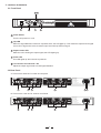
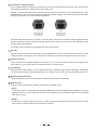
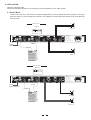
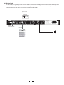
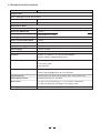
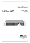
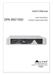
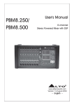
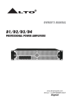
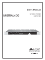
User's Manual
MISTRAL400
STEREO POWER
AMPLIFIER
R
LTO
www.altoproaudio.com
Version 1.1 MAY 2005
English
SAFETY RELATED SYMBOLS
Never cut off the internal or external protective grounding
wire or disconnect the wiring of protective grounding terminal.
CAUTION
RISK OF ELECTRIC SHOCK
DO NOT OPEN
Operating Conditions
This apparatus shall not be exposed to dripping or splashing and that no objects filled with liquids, such as
vases, shall be placed on this apparatus.
To reduce the risk of fire or electric shock, do not expose
this apparatus to rain or moisture.
Do not use this apparatus near water.
Install in accordance with the manufacturer's instructions.
Do not install near any heat sources such as radiators,
heat registers, stoves, or other apparatus (including amplifiers) that produce heat.
Do not block any ventilation openings.
No naked flame sources, such as lighted candles, should
be placed on the apparatus.
The symbol is used to indicate that some hazardous live terminals are involved within this apparatus,
even under the normal operating conditions.
The symbol is used in the service documentation
to indicate that a specific component shall be only
replaced by the component specified in that documentation for safety reasons.
Protective grounding terminal.
Alternating current /voltage.
Hazardous live terminal.
ON: Denotes the apparatus is turned on.
OFF: Denotes the apparatus is turned off, because it uses
the single pole switch, be sure to unplug the AC power to
prevent any electric shock before you proceed with your
service.
IMPORTANT SAFETY INSTRUCTIONS
Read these instructions.
Follow all instructions.
Keep these instructions.
Heed all warnings.
Only use attachments/accessories specified by the manufacturer.
WARNING: Describes precautions that should be
observed to prevent the danger of injury or death to
the user.
CAUTION: Describes precautions that should be
observed to prevent danger of the apparatus.
Power Cord and Plug
Do not defeat the safety purpose of the polarized or
grounding type plug. A polarized plug has two blades
with one wider than the other. A grounding type plug
has two blades and a third grounding prong. The wide
blade or the third prong are provided for your safety.
If the provided plug does not fit into your outlet, consult
an electrician for replacement of the obsolete outlet.
Protect the power cord from being walked on or pinched
particularly at the plug, convenience receptacles, and
the point where they exit from the apparatus.
WARNING
Power Supply
Ensures the source voltage matches the voltage of the
power supply before turning ON the apparatus.
Unplug this apparatus during lightning storms or when
unused for long periods of time.
External Connection
The external wiring connected to the output hazardous
live terminals requires installation by an instructed person,
or the use of ready-made leads or cords.
Cleaning
When the apparatus needs a cleaning, you can blow off
dust from the apparatus with a blower or clean with a rag
etc. Don't use solvents such as benzol, alcohol, or other
fluids with very strong volatility and flammability for cleaning
the apparatus body.
Clean only with a dry cloth.
Do not Remove any Cover
There are maybe some areas with high voltages inside,
to reduce the risk of electric shock, do not remove any
cover if the power supply is connected.
The cover should be removed by qualified personnel
only.
No user serviceable parts inside.
Servicing
Refer all servicing to qualified personnel. To reduce the
risk of electric shock, do not perform any servicing other
than that contained in the operating instructions unless
you are qualified to do so.
Servicing is required when the apparatus has been damaged in any way, such as the power supply cord or plug
is damaged, liquid has been spilled or objects have fallen
into the apparatus, the apparatus has been exposed to
rain or moisture, does not operate normally, or has been
dropped.
Fuse
To prevent a fire, make sure to use fuses with specified
standard (current, voltage, type). Do not use a different
fuse or short circuit the fuse holder.
Before replacing the fuse, turn OFF the apparatus and
dis-connect the power source.
Protective Grounding
Make sure to connect the protective grounding to prevent
any electric shock before turning ON the apparatus.
1
Preface
Dear Customer:
Thanks for choosing LTO MISTRAL400 Stereo Power Amplifier and thanks for choosing one of the results of
AUDIO TEAM job and researches.
LTO
For our LTO AUDIO TEAM, music and sound are more than a job ...are first of all passion and let us say...our obsession!
We have been designing professional audio products for a long time in cooperation with some of the major brands in the
world in the audio field.
The LTO line presents unparalleled analogue and digital products made by Musicians for Musicians in our R&D Centers
in Italy Netherlands, United Kingdom and Taiwan. The core of our digital audio products is a sophisticated DSP (Digital
Sound Processor) and a large range of state of the art algorithms which have been developed by our Software Team for
the last 7 years.
Because we are convinced you are the most important member of LTO AUDIO TEAM and the one confirming the quality
of our job, we'd like to share with you our work and our dreams, paying attention to your suggestions and your comments.
Following this idea we create our products and we will create the new ones! From our side, we guarantee you and we
will guarantee you also in future the best quality, and the best fruits of our continuous researches and the best prices.
Our LTO MISTRAL400 Stereo Power Amplifier is the result of many hours of listening and tests involving common people,
area experts, musicians and technicians.The result of this effort is the sophisticated circuit design featuring high power
and superb quality together with superiorreliability and stability to provide the highest possible audio performance.
Nothing else to add, but that we would like to thank all the people that made the LTO MISTRAL400 Stereo Power Amplifier
a reality available to our customers, and thank our designers and all the LTO staff, there to make possible therealization of
products containing our idea of music and sound and there to support you, our customers, In the best way, conscious that you
are our best richness.
Thank you very much.
LTO AUDIO TEAM
2
TABLE OF CONTENTS
1. INTRODUCTION.......................................................................................................................................4
2. FEATURES .... .........................................................................................................................................4
3. CONTROL ELEMENTS............................................................................................................................5
3.1 The Front Panel
3.2 The Rear Panel
4. APPLICATION.......................................................................................................................................7
4.1 Stereo Mode
4.2 Bridge Mode
5. TECHNICAL SPECIFICATIONS...........................................................................................................9
6. WARRANTY ........................................................................................................................................10
3
1. INTRODUCTION
The LTO MISTRAL400 is a line of high power, low profile, professional Power Amplifiers with advanced features
and great reliability. They deliver tremendous power in only one rack space, providing high level performance under
the most demanding conditions. The amplifier frame contains all solid-state circuitry, using complementary silicon
output devices. The amplifier contains two independent channels, with separate AC transformer secondaries. Each
channel has also a main LED that becomes blue for power-on indicator, another red LED that shows true amplifier
clipping and a yellow one for the Limiter Stage. The Power outputs employ standard power connectors. All the inputs
are electronically balanced and an high quality audio transformer can be added on the input stage of each channel.
2. FEATURES
1U rack, stereo high power amplifier.
Fantastic audio quality even with extremely high volume levels.
Solid and durable, can be mounted into a cabinet.
User-controllable clip limiter.
2x100 Watts (EIAJ) RMS on 4 ohms for MISTRAL400.
Stereo (dual-channel), or bridge mono operating modes.
Balanced XLR inputs to ensure noiseless long wiring.
Neutrik Speak-on connectors for output.
Single channel, bridge, and bi-amp output wiring possibility.
Front panel LED indicators for limit, power on and clip.
Accurate gain control.
Manufactured under QS9000, VDA 6.1 certified management system.
4
3. CONTROL ELEMENTS
3.1 Front Panel
2 3
R
LTO
1
5
4
5
1 Power Switch
Turn the unit power on or off.
2 Clip LED
When the signal distortion reaches or surpasses 0.5%, the LED lights up. This means the output level of signal
source is too high and it is time to reduce input level until clip LED turning off.
3 Output Limiter LED
While the unit is limiting the output signal, the LED lighting up.
4 Power LED
This LED lights up when the unit is powered.
5 Level Control for Channels 1 & 2
Adjust the output signal level to avoid signal distortion.
3.2 Rear Panel
A. This is set for 220V AC TO 240V AC rear panel
CH2
MODE
STEREO
BRIDGE
NEW
TIDE
LIMITER
3
2
CH1
INPUT
TIP/PIN 2
RING/PIN 3
SLEEVE/PIN 1
OFF
ON
1
NEW
TIDE
TIP/PIN 2
RING/PIN 3
SLEEVE/PIN 1
CH2
1+
1POS NEG
POWER
OUTPUTS
CH2
SP
SP
CH1
SP
SP
TIP
TIP
CH2
2+
2POS NEG
3
2
CH1
1+
1POS NEG
1
BRIDGE
1+
2+
POS NEG
Apparaten skall anslutas
till jordat uttag nar den
ansluts till ett natverk
AC INPUT: 220-240V 50-60Hz
FUSE: T1.6AL 250VAC
Use only with a 250V fuse
Rated Power Consumption 200W
REPLACE FUSE WITH CORRECT TYPE ONLY
11
10
9
8
6 7
B. This is set for 110V AC TO 120V AC rear Panel
CH2
MODE
STEREO
BRIDGE
NEW
TIDE
LIMITER
3
2
CH1
INPUT
TIP/PIN 2
RING/PIN 3
SLEEVE/PIN 1
OFF
ON
1
NEW
TIDE
TIP/PIN 2
RING/PIN 3
SLEEVE/PIN 1
CH2
1+
1POS NEG
POWER
OUTPUTS
CH2
SP
SP
3
2
CH1
SP
SP
TIP
1
Class
two wiring
TIP
CH1
1+
1POS NEG
CH2
2+
2POS NEG
BRIDGE
1+
2+
POS NEG
Apparaten skall anslutas
till jordat uttag nar den
ansluts till ett natverk
AC INPUT: 110-120V 50-60Hz
FUSE: T3.15AL 250VAC
Use only with a 250V fuse
Rated Power Consumption 200W
REPLACE FUSE WITH CORRECT TYPE ONLY
11
10
8
9
5
6 7
6 Fuse Holder / Voltage Selector
This is a dual voltage unit. Before you attempt to connect and operate the unit, please make sure that your
Local voltage matches the voltage on the fuse holder cover.
Caution: The fuse protecting the AC supplies circuits of this unit. The fuse can only be changed by a qualified technician, in the event of a fault or changing the supply voltage. If the fuse continues to blow after
replacing, discontinue use of this unit before repaired.
110-120V
220-240V
USE ONLY WITH A 250V FUSE
EMPLOYER UNIQUEMENT AVEC
UN FUSIBLE DE 250V
USE ONLY WITH A 250V FUSE
EMPLOYER UNIQUEMENT AVEC
UN FUSIBLE DE 250V
110-120V
220-240V
A
B
THIS IS SET FOR
220V AC TO 240V
AC OPERATION
THIS IS SET FOR
110V AC TO 120V
AC OPERATION
The fuse holder above the AC connector on the rear of the chassis has 3 triangular markers (please refer to
the above pictures), with two of these triangles opposing each other, your unit is set to the operating voltage
printed next to these markers.
To change, pull fuse holder out and rotate 1800, then push in again.
7 AC Inlet
This connector is meant for the connection of the supplied main cord. Do not insert power cord into unit until
voltage has been correctly set. Do not plug power cord into AC power until voltage has been correctly set.
8 Output Connector
These connectors are Neutrik speakon connectors. You can choose proper connectors according to practical need. For your safety, please be careful when do connecting work.
9
Limit Switch
Set this switch at "ON" position, once the output level is above maximum output level, the clip begin, thus keeping
consistent output level for protecting apparatus. If the switch is set at "OFF", this clip function doesn't work.
10
Balanced Input Connector
These connectors connect the input signal of channel1 and channel 2 separately.
11
Mode Selector
Total two optional modes: Up for Stereo mode; Down for Bridge mode.
- Stereo
In this mode, Channel 1 and Channel 2 operate independently ( just as traditional stereo amplifier). The signal
input into channel 1 can be output from channel 1 only, similarly, the signal input into channel 2 can be output
from channel 2 only.
- Bridge
In this mode, the signal input into channel 1 will be output from the bridged end, on other hand, the output
level control of channel 2 should be turn down to smallest.
6
4. APPLICATION
Total two optional modes:
Please see following diagram for connecting the power amplifier into your audio system.
4.1 Stereo Mode
In this mode, Channel 1 and Channel 2 operate independently ( just as traditional stereo amplifier). The signal
input into channel 1 can be output from channel 1 only, similarly, the signal input into channel 2 can be output from
channel 2 only.
+
Input Connector
Balanced
Channel 1
GND
1
3
2
INPUT
CH2
MODE
STEREO
BRIDGE
NEW
TIDE
CH1
INPUT
TIP/PIN 2
RING/PIN 3
SLEEVE/PIN 1
LIMITER
3
2
NEW
TIDE
CH2
1+
1POS NEG
CH2
SP
SP
POWER
OUTPUTS
CH1
SP
SP
TIP
TIP
2
CH1
1+
1POS NEG
CH2
2+
2POS NEG
3
OFF
ON
1
TIP/PIN 2
RING/PIN 3
SLEEVE/PIN 1
1
BRIDGE
1+
2+
POS NEG
Apparaten skall anslutas
till jordat uttag nar den
ansluts till ett natverk
AC INPUT: 220-240V 50-60Hz
FUSE: T1.6AL 250VAC
Use only with a 250V fuse
Rated Power Consumption 200W
REPLACE FUSE WITH CORRECT TYPE ONLY
Channel 1
MODE
Release this button
Channel 2
+
Channel 2
Input Connector
Balanced
GND
1
3
2
INPUT
CH2
MODE
STEREO
BRIDGE
NEW
TIDE
CH1
INPUT
TIP/PIN 2
RING/PIN 3
SLEEVE/PIN 1
LIMITER
3
2
OFF
ON
1
NEW
TIDE
TIP/PIN 2
RING/PIN 3
SLEEVE/PIN 1
CH2
1+
1POS NEG
CH2
SP
SP
TIP
3
2
1
POWER
OUTPUTS
CH1
SP
SP
TIP
CH1
1+
1POS NEG
CH2
2+
2POS NEG
BRIDGE
1+
2+
POS NEG
Apparaten skall anslutas
till jordat uttag nar den
ansluts till ett natverk
AC INPUT: 220-240V 50-60Hz
FUSE: T1.6AL 250VAC
Use only with a 250V fuse
Rated Power Consumption 200W
REPLACE FUSE WITH CORRECT TYPE ONLY
Channel 1
MODE
Release this button
Channel 2
+
Channel 1
+
Channel 2
7
4.2 Bridge Mode
In this mode, the signal input into channel 1 will be output from the bridged end, on other hand, the output level
control of channel 2 should be turn down to smallest (turn the volume control at counterclockwise). Only the volume
control of channel 1 is used to control the volume of whole system.
Input Connector
Balanced
GND
1
3
2
INPUT
CH2
MODE
STEREO
BRIDGE
NEW
TIDE
3
2
1
CH1
INPUT
TIP/PIN 2
RING/PIN 3
SLEEVE/PIN 1
LIMITER
OFF
ON
NEW
TIDE
TIP/PIN 2
RING/PIN 3
SLEEVE/PIN 1
CH2
1+
1POS NEG
CH2
SP
SP
TIP
3
2
1
POWER
OUTPUTS
CH1
SP
SP
TIP
CH1
1+
1POS NEG
CH2
2+
2POS NEG
BRIDGE
1+
2+
POS NEG
Apparaten skall anslutas
till jordat uttag nar den
ansluts till ett natverk
AC INPUT: 220-240V 50-60Hz
FUSE: T1.6AL 250VAC
Use only with a 250V fuse
Rated Power Consumption 200W
REPLACE FUSE WITH CORRECT TYPE ONLY
MODE
Press this button
Channel 1
Channel 2+ Channel 1+ +
8
5. TECHNICAL SPECIFICATIONS
MODEL
MISTRAL400
Output Power
20Hz [email protected]%THD, Stereo Mode
8 ohms per channel(EIAJ)
60W
4 ohms per channel(EIAJ)
100W
Bridge Mono Mode
8 ohms, 1KHz, 0.1%THD
180W
Distortion (SMPTE-IM)
<0.05%
Frequency Response
20Hz-20KHz+0.1/ -3dB
Damping Factor, 1 kHz and below
>300 at 8ohms
Signal to Noise,20Hz-20KHz
102dB
Voltage Gain
40x (32dB)
Input Sensitivity @ 4 ohms
1Vrms
Input Clipping
10Vrms (+22dB)
Input Impedance
10K ohms unbalanced, 20K ohms balanced 56 (36dB)
Controls
FRONT: AC SWITCH, CH1 & CH2 GAIN KNOBS
REAR: LIMITER, BRIDGE SELECTOR
Indicators (1 per channel)
Power-On: Blue LED
Limit: Yellow LED
Clip: Red LED
Connectors, each channel
Input: Active balanced XLR and 1/4''TRS jack
Output: NEUTRIK R Speakon and 1/4''TRS jack
Load Protection
On/off muting, DC-fault load grounding relay. Internal fault fuses.
Power Requirements
220-240(110-120) Vac 50~60Hz
Dimensions
19" (48.3 cm) rack mounting, 1.7" (4.4 cm) tall (1 rack space),
11" (28 cm) deep (rack mounting to rear support ears)
Net Weight
7.5Kg
9
6. WARRANTY
1. WARRANTY REGISTRATION CARD
To obtain Warranty Service, the buyer should first fill out and return the enclosed Warranty Registration Card within
10 days of the Purchase Date.
All the information presented in this Warranty Registration Card gives the manufacturer a better understanding of
the sales status, so as to purport a more effective and efficient after-sales warranty service.
Please fill out all the information carefully and genuinely, miswriting or absence of this card will void your warranty
service.
2. RETURN NOTICE
2.1 In case of return for any warranty service, please make sure that the product is well packed in its original shipping
carton, and it can protect your unit from any other extra damage.
2.2 Please provide a copy of your sales receipt or other proof of purchase with the returned machine, and give detail
information about your return address and contact telephone number.
2.3 A brief description of the defect will be appreciated.
2.4 Please prepay all the costs involved in the return shipping, handling and insurance.
3. TERMS AND CONDITIONS
3.1
LTO warrants that this product will be free from any defects in materials and/or workmanship for a period
of 1 year from the purchase date if you have completed the Warranty Registration Card in time.
3.2 The warranty service is only available to the original consumer, who purchased this product directly from the
retail dealer, and it can not be transferred.
3.3 During the warranty service, LTO may repair or replace this product at its own option at no charge to you for
parts or for labor in accordance with the right side of this limited warranty.
3.4 This warranty does not apply to the damages to this product that occurred as the following conditions:
Instead of operating in accordance with the user's manual thoroughly, any abuse or misuse of this product.
Normal tear and wear.
The product has been altered or modified in any way.
Damage which may have been caused either directly or indirectly by another product / force / etc.
Abnormal service or repairing by anyone other than the qualified personnel or technician.
And in such cases, all the expenses will be charged to the buyer.
3.5 In no event shall LTO be liable for any incidental or consequential damages. Some states do not allow the exclusion or limitation of incidental or consequential damages, so the above exclusion or limitation may not apply to you.
3.6 This warranty gives you the specific rights, and these rights are compatible with the state laws, you may also
have other statutory rights that may vary from state to state.
10
SEIKAKU TECHNICAL GROUP LIMITED
SEKAKU ELECTRON INDUSTRY (H.K.) CO., LTD.
No. 1, Lane 17, Sec. 2, Han Shi West Road, Taichung 40151, Taiwan
http://www.altoproaudio.com Tel: 886-4-22313737
email: [email protected] Fax: 886-4-22346757
All rights reserved to ALTO. All features and content might be changed
without prior notice. Any photocopy, translation, or reproduction of part of this
manual without written permission is forbidden. Copyright c 2005 SEIKAKU GROUP
NF02036-1.1