1
YASKAWA
NX100
INFORM MANUAL
Upon receipt of the product and prior to initial operation, read these instructions thoroughly, and retain
for future reference.
MOTOMAN INSTRUCTIONS
MOTOMANINSTRUCTIONS
NX100 INSTRUCTIONS
NX100 OPERATOR’S MANUAL
NX100 MAINTENANCE MANUAL
The NX100 operator’s manuals above correspond to specific usage.
Be sure to use the appropriate manual.
YASKAWA
MANUAL NO. RE-CKI-A444
MANDATORY
• This manual explains the INFORM language of the NX100 system. Read
this manual carefully and be sure to understand its contents before handling the NX100.
• General items related to safety are listed in the Section 1: Safety of the
NX100 Instructions. To ensure correct and safe operation, carefully
read the NX100 Instructions before reading this manual.
CAUTION
• Some drawings in this manual are shown with the protective covers or
shields removed for clarity. Be sure all covers and shields are replaced
before operating this product.
• The drawings and photos in this manual are representative examples
and differences may exist between them and the delivered product.
• YASKAWA may modify this model without notice when necessary due to
product improvements, modifications, or changes in specifications. If
such modification is made, the manual number will also be revised.
• If your copy of the manual is damaged or lost, contact a YASKAWA representative to order a new copy. The representatives are listed on the
back cover. Be sure to tell the representative the manual number listed
on the front cover.
• YASKAWA is not responsible for incidents arising from unauthorized
modification of its products. Unauthorized modification voids your product’s warranty.
ii
NOTES FOR SAFE OPERATION
Read this manual carefully before installation, operation, maintenance, or inspection of the
NX100.
In this manual, the Notes for Safe Operation are classified as “WARNING”, “CAUTION”,
“MANDATORY”, or ”PROHIBITED”.
WARNING
Indicates a potentially hazardous situation which, if not avoided,
could result in death or serious injury to personnel.
CAUTION
Indicates a potentially hazardous situation which, if not avoided,
could result in minor or moderate injury to personnel and damage to equipment. It may also be used to alert against unsafe
practices.
MANDATORY
Always be sure to follow explicitly the items listed under this
heading.
PROHIBITED
Must never be performed.
Even items described as “CAUTION” may result in a serious accident in some situations. At
any rate, be sure to follow these important items.
NOTE
To ensure safe and efficient operation at all times, be sure to follow all instructions, even if
not designated as “CAUTION” and “WARNING”.
iii
WARNING
• Before operating the manipulator, check that servo power is turned OFF
when the emergency stop buttons on the front door of the NX100 and
programming pendant are pressed.
When the servo power is turned OFF, the SERVO ON LED on the programming pendant is turned OFF.
Injury or damage to machinery may result if the emergency stop circuit cannot stop the
manipulator during an emergency. The manipulator should not be used if the emergency
stop buttons do not function.
Emergency Stop Button
• Once the emergency stop button is released, clear the cell of all items
which could interfere with the operation of the manipulator. Then turn
the servo power ON
Injury may result from unintentional or unexpected manipulator motion.
TURN
Release of Emergency Stop
• Observe the following precautions when performing teaching operations
within the P-point maximum envelope of the manipulator:
- View the manipulator from the front whenever possible.
- Always follow the predetermined operating procedure.
- Ensure that you have a safe place to retreat in case of emergency.
Improper or unintended manipulator operation may result in injury.
• Confirm that no person is present in the P-point maximum envelope of
the manipulator and that you are in a safe location before:
- Turning ON the NX100 power
- Moving the manipulator with the programming pendant
- Running the system in the check mode
- Performing automatic operations
Injury may result if anyone enters the P-point maximum envelope of the manipulator during operation. Always press an emergency stop button immediately if there is a problem.
The emergency stop buttons are located on the right of the front door of the NX100 and
the programming pendant.
iv
CAUTION
• Perform the following inspection procedures prior to conducting manipulator teaching. If problems are found, repair them immediately, and be
sure that all other necessary processing has been performed.
-Check for problems in manipulator movement.
-Check for damage to insulation and sheathing of external wires.
• Always return the programming pendant to the hook on the NX100 cabinet after use.
The programming pendant can be damaged if it is left in the manipulator’s work area, on
the floor, or near fixtures.
• Read and understand the Explanation of the Warning Labels in the
NX100 Instructions before operating the manipulator.
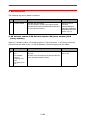
Definition of Terms Used Often in This Manual
The MOTOMAN manipulator is the YASKAWA industrial robot product.
The manipulator usually consists of the controller, the programming pendant, and supply
cables.
In this manual, the equipment is designated as follows.
Equipment
Manual Designation
NX100 Controller
NX100
NX100 Programming Pendant
Programming Pendant
Cable between the manipulator and the controller
Manipulator Cable
v
Descriptions of the programming pendant keys, buttons, and displays are shown as follows:
Equipment
Programming
Pendant
Manual Designation
Character Keys
The keys which have characters printed on them are
denoted with [ ].
ex. [ENTER]
Symbol Keys
The keys which have a symbol printed on them are
not denoted with [ ] but depicted with a small picture.
GO BACK
ex. page key
The cursor key is an exception, and a picture is not
shown.
PAGE
Axis Keys
Numeric Keys
“Axis Keys” and “Numeric Keys” are generic names
for the keys for axis operation and number input.
Keys pressed
simultaneously
When two keys are to be pressed simultaneously,
the keys are shown with a “+” sign between them,
ex. [SHIFT]+[COORD]
Displays
The menu displayed in the programming pendant is
denoted with { }.
ex. {JOB}
Description of the Operation Procedure
In the explanation of the operation procedure, the expression "Select • • • " means that the
cursor is moved to the object item and the SELECT key is pressed.
vi
1
INFORM Manual Outline
1.1 About INFORM
1.1.1
1.1.2
1.1.3
1.1.4
. . . . . . . . . . . . . . . . . . . . . . . . . . . . . . . . . . . .1-1
With INFORM II . . . . . . . . . . . . . . . . . . . . . . . . . . . . . . . . . . . . .1-1
Type of Instruction . . . . . . . . . . . . . . . . . . . . . . . . . . . . . . . . . . .1-1
Instruction Set . . . . . . . . . . . . . . . . . . . . . . . . . . . . . . . . . . . . . .1-2
Selecting Instruction Set . . . . . . . . . . . . . . . . . . . . . . . . . . . .1-2
Variables to be Used in Instructions . . . . . . . . . . . . . . . . . . . . .1-3
Set Value of Variable and Numeric Data. . . . . . . . . . . . . . . .1-3
1.2 Registration of Instructions
. . . . . . . . . . . . . . . . . . . . . . . . .1-4
1.2.1 Registration . . . . . . . . . . . . . . . . . . . . . . . . . . . . . . . . . . . . . . . .1-4
1.2.2 Learning Function . . . . . . . . . . . . . . . . . . . . . . . . . . . . . . . . . . .1-5
1.3 Detail Edit Window . . . . . . . . . . . . . . . . . . . . . . . . . . . . . . . . .1-7
1.4 Registration of Expression . . . . . . . . . . . . . . . . . . . . . . . . . .1-8
1.4.1 Expression. . . . . . . . . . . . . . . . . . . . . . . . . . . . . . . . . . . . . . . . .1-8
1.4.2 Registration . . . . . . . . . . . . . . . . . . . . . . . . . . . . . . . . . . . . . . .1-10
1.5 INFORM Structure . . . . . . . . . . . . . . . . . . . . . . . . . . . . . . . . .1-12
INFORM Structure Elements. . . . . . . . . . . . . . . . . . . . . . . .1-13
Meaning of INFORM Structure . . . . . . . . . . . . . . . . . . . . . .1-13
Explanation Table . . . . . . . . . . . . . . . . . . . . . . . . . . . . . . . .1-14
2
INFORM Explanation
2.1 I/O Instructions . . . . . . . . . . . . . . . . . . . . . . . . . . . . . . . . . . . . .2-1
2.2
2.3
DOUT . . . . . . . . . . . . . . . . . . . . . . . . . . . . . . . . . . . . . . . . . . . . .2-1
DIN . . . . . . . . . . . . . . . . . . . . . . . . . . . . . . . . . . . . . . . . . . . . . . .2-4
WAIT . . . . . . . . . . . . . . . . . . . . . . . . . . . . . . . . . . . . . . . . . . . . . .2-7
PULSE . . . . . . . . . . . . . . . . . . . . . . . . . . . . . . . . . . . . . . . . . . .2-12
AOUT . . . . . . . . . . . . . . . . . . . . . . . . . . . . . . . . . . . . . . . . . . . .2-15
ARATION . . . . . . . . . . . . . . . . . . . . . . . . . . . . . . . . . . . . . . . . .2-16
ARATIOF . . . . . . . . . . . . . . . . . . . . . . . . . . . . . . . . . . . . . . . . .2-20
ANTOUT . . . . . . . . . . . . . . . . . . . . . . . . . . . . . . . . . . . . . . . . . .2-21
Control Instruction . . . . . . . . . . . . . . . . . . . . . . . . . . . . . . . . .2-26
JUMP . . . . . . . . . . . . . . . . . . . . . . . . . . . . . . . . . . . . . . . . . . . .2-26
CALL . . . . . . . . . . . . . . . . . . . . . . . . . . . . . . . . . . . . . . . . . . . . .2-30
TIMER . . . . . . . . . . . . . . . . . . . . . . . . . . . . . . . . . . . . . . . . . . . .2-33
* (LABEL) . . . . . . . . . . . . . . . . . . . . . . . . . . . . . . . . . . . . . . . . .2-34
’ (COMMENT) . . . . . . . . . . . . . . . . . . . . . . . . . . . . . . . . . . . . . .2-35
RET . . . . . . . . . . . . . . . . . . . . . . . . . . . . . . . . . . . . . . . . . . . . . .2-36
NOP . . . . . . . . . . . . . . . . . . . . . . . . . . . . . . . . . . . . . . . . . . . . .2-37
PAUSE . . . . . . . . . . . . . . . . . . . . . . . . . . . . . . . . . . . . . . . . . . .2-38
CWAIT . . . . . . . . . . . . . . . . . . . . . . . . . . . . . . . . . . . . . . . . . . .2-39
ADVINIT . . . . . . . . . . . . . . . . . . . . . . . . . . . . . . . . . . . . . . . . . .2-40
ADVSTOP . . . . . . . . . . . . . . . . . . . . . . . . . . . . . . . . . . . . . . . . .2-41
Operating Instruction . . . . . . . . . . . . . . . . . . . . . . . . . . . . . .2-42
CLEAR . . . . . . . . . . . . . . . . . . . . . . . . . . . . . . . . . . . . . . . . . . .2-42
INC . . . . . . . . . . . . . . . . . . . . . . . . . . . . . . . . . . . . . . . . . . . . . .2-46
DEC . . . . . . . . . . . . . . . . . . . . . . . . . . . . . . . . . . . . . . . . . . . . .2-48
SET . . . . . . . . . . . . . . . . . . . . . . . . . . . . . . . . . . . . . . . . . . . . . .2-50
ADD . . . . . . . . . . . . . . . . . . . . . . . . . . . . . . . . . . . . . . . . . . . . .2-60
SUB . . . . . . . . . . . . . . . . . . . . . . . . . . . . . . . . . . . . . . . . . . . . .2-69
vii
MUL . . . . . . . . . . . . . . . . . . . . . . . . . . . . . . . . . . . . . . . . . . . . . 2-79
DIV . . . . . . . . . . . . . . . . . . . . . . . . . . . . . . . . . . . . . . . . . . . . . . 2-89
CNVRT . . . . . . . . . . . . . . . . . . . . . . . . . . . . . . . . . . . . . . . . . . . 2-98
AND . . . . . . . . . . . . . . . . . . . . . . . . . . . . . . . . . . . . . . . . . . . . 2-101
OR . . . . . . . . . . . . . . . . . . . . . . . . . . . . . . . . . . . . . . . . . . . . . 2-103
NOT . . . . . . . . . . . . . . . . . . . . . . . . . . . . . . . . . . . . . . . . . . . . 2-105
XOR . . . . . . . . . . . . . . . . . . . . . . . . . . . . . . . . . . . . . . . . . . . . 2-107
MFRAME . . . . . . . . . . . . . . . . . . . . . . . . . . . . . . . . . . . . . . . . 2-109
SETE . . . . . . . . . . . . . . . . . . . . . . . . . . . . . . . . . . . . . . . . . . . 2-112
GETE . . . . . . . . . . . . . . . . . . . . . . . . . . . . . . . . . . . . . . . . . . . 2-115
GETS . . . . . . . . . . . . . . . . . . . . . . . . . . . . . . . . . . . . . . . . . . . 2-117
SQRT . . . . . . . . . . . . . . . . . . . . . . . . . . . . . . . . . . . . . . . . . . . 2-123
SIN . . . . . . . . . . . . . . . . . . . . . . . . . . . . . . . . . . . . . . . . . . . . . 2-125
COS . . . . . . . . . . . . . . . . . . . . . . . . . . . . . . . . . . . . . . . . . . . . 2-127
ATAN . . . . . . . . . . . . . . . . . . . . . . . . . . . . . . . . . . . . . . . . . . . 2-129
MULMAT . . . . . . . . . . . . . . . . . . . . . . . . . . . . . . . . . . . . . . . . 2-131
INVMAT . . . . . . . . . . . . . . . . . . . . . . . . . . . . . . . . . . . . . . . . . 2-134
SETFILE . . . . . . . . . . . . . . . . . . . . . . . . . . . . . . . . . . . . . . . . . 2-136
GETFILE . . . . . . . . . . . . . . . . . . . . . . . . . . . . . . . . . . . . . . . . 2-140
2.4 Move Instruction . . . . . . . . . . . . . . . . . . . . . . . . . . . . . . . . . 2-142
MOVJ . . . . . . . . . . . . . . . . . . . . . . . . . . . . . . . . . . . . . . . . . . . 2-142
MOVL . . . . . . . . . . . . . . . . . . . . . . . . . . . . . . . . . . . . . . . . . . . 2-153
MOVC . . . . . . . . . . . . . . . . . . . . . . . . . . . . . . . . . . . . . . . . . . 2-164
MOVS . . . . . . . . . . . . . . . . . . . . . . . . . . . . . . . . . . . . . . . . . . . 2-173
IMOV . . . . . . . . . . . . . . . . . . . . . . . . . . . . . . . . . . . . . . . . . . . 2-182
SPEED . . . . . . . . . . . . . . . . . . . . . . . . . . . . . . . . . . . . . . . . . . 2-190
REFP . . . . . . . . . . . . . . . . . . . . . . . . . . . . . . . . . . . . . . . . . . . 2-193
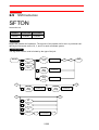
2.5 Shift Instruction . . . . . . . . . . . . . . . . . . . . . . . . . . . . . . . . . . 2-200
SFTON . . . . . . . . . . . . . . . . . . . . . . . . . . . . . . . . . . . . . . . . . . 2-200
SFTOF . . . . . . . . . . . . . . . . . . . . . . . . . . . . . . . . . . . . . . . . . . 2-205
MSHIFT . . . . . . . . . . . . . . . . . . . . . . . . . . . . . . . . . . . . . . . . . 2-207
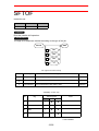
2.6 Instruction Which Adheres to an Instruction. . . . . . . 2-210
IF . . . . . . . . . . . . . . . . . . . . . . . . . . . . . . . . . . . . . . . . . . . . . . 2-210
UNTIL . . . . . . . . . . . . . . . . . . . . . . . . . . . . . . . . . . . . . . . . . . . 2-223
ENWAIT . . . . . . . . . . . . . . . . . . . . . . . . . . . . . . . . . . . . . . . . . 2-225
2.7 Arc Welding Instruction . . . . . . . . . . . . . . . . . . . . . . . . . . . 2-226
ARCON . . . . . . . . . . . . . . . . . . . . . . . . . . . . . . . . . . . . . . . . . 2-226
ARCOF . . . . . . . . . . . . . . . . . . . . . . . . . . . . . . . . . . . . . . . . . . 2-231
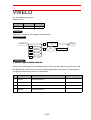
VWELD . . . . . . . . . . . . . . . . . . . . . . . . . . . . . . . . . . . . . . . . . 2-235
AWELD . . . . . . . . . . . . . . . . . . . . . . . . . . . . . . . . . . . . . . . . . 2-237
ARCSET . . . . . . . . . . . . . . . . . . . . . . . . . . . . . . . . . . . . . . . . . 2-239
WVON . . . . . . . . . . . . . . . . . . . . . . . . . . . . . . . . . . . . . . . . . . 2-243
WVOF . . . . . . . . . . . . . . . . . . . . . . . . . . . . . . . . . . . . . . . . . . 2-249
ARCCTS . . . . . . . . . . . . . . . . . . . . . . . . . . . . . . . . . . . . . . . . 2-251
ARCCTE . . . . . . . . . . . . . . . . . . . . . . . . . . . . . . . . . . . . . . . . 2-255
2.8 Handling Instruction . . . . . . . . . . . . . . . . . . . . . . . . . . . . . . 2-259
HAND . . . . . . . . . . . . . . . . . . . . . . . . . . . . . . . . . . . . . . . . . . . 2-259
HSEN . . . . . . . . . . . . . . . . . . . . . . . . . . . . . . . . . . . . . . . . . . . 2-261
2.9 Spot Welding Instruction . . . . . . . . . . . . . . . . . . . . . . . . . 2-263
GUNCL . . . . . . . . . . . . . . . . . . . . . . . . . . . . . . . . . . . . . . . . . . 2-263
SPOT . . . . . . . . . . . . . . . . . . . . . . . . . . . . . . . . . . . . . . . . . . . 2-265
STROKE . . . . . . . . . . . . . . . . . . . . . . . . . . . . . . . . . . . . . . . . 2-269
STRWAIT . . . . . . . . . . . . . . . . . . . . . . . . . . . . . . . . . . . . . . . . 2-270
2.10 General-purpose Instruction . . . . . . . . . . . . . . . . . . . . 2-272
TOOLON . . . . . . . . . . . . . . . . . . . . . . . . . . . . . . . . . . . . . . . . 2-272
TOOLOF . . . . . . . . . . . . . . . . . . . . . . . . . . . . . . . . . . . . . . . . 2-274
viii
1.1 About INFORM
1 INFORM Manual Outline
1.1
About INFORM
1.1.1
With INFORM II
The robot programming language used with NX100 is called INFORM II. INFORM II is composed of the instruction and the additional item (tag and numeric data).
MOVJ VJ=50.00
Tag
Numeric data
Instruction
Additional item
• Instruction : It is used to execute the operation and processing. In the case of a move
instruction, when a position is taught, the move instruction is automatically displayed
according to the interpolation method.
• Additional item : The speed, time, etc. are set according to the type of instruction.
Numeric data and character data are added to the tag that specifies the condition as necessary.
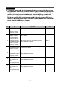
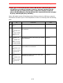
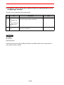
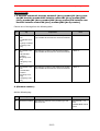
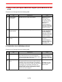
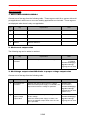
1.1.2
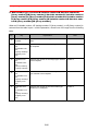
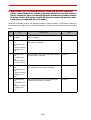
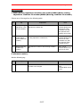
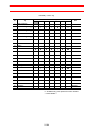
Type of Instruction
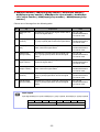
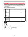
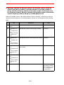
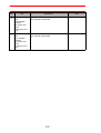
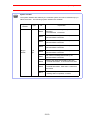
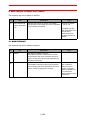
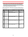
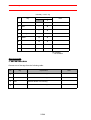
The instruction is divided into several types in terms of each process and operation.
Type
Content
Instruction Example
I/O Instruction
It is the instruction used to control the I/O.
Control
Instruction
It is the instruction used to control the processing and oper- JUMP, TIMER
ation.
Operating
Instruction
It is the instruction by which the variables, etc. are used and ADD, SET
operated.
Move Instruction
It is an instruction concerning the movement and the speed. MOVJ, REFP
Shift Instruction
It is an instruction used when a present teaching position is SFTON, SFTOF
shifted.
Instruction which
adheres to
instruction
It is an instruction which adheres to the instruction.
Work Instruction
It is an instruction concerning work, such as arc welding and ARCON, WVON
handling.
Optional
Instruction
It is an instruction concerning optional functions. It can only
be used when the function is available.
1-1
DOUT, WAIT
IF, UNTIL
-
1.1 About INFORM
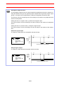
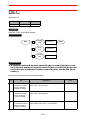
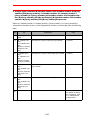
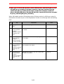
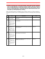
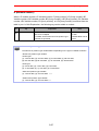
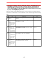
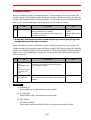
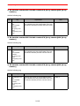
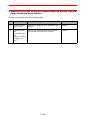
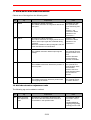
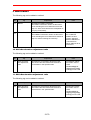
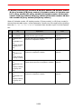
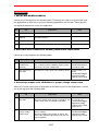
1.1.3
Instruction Set
To improve operation efficiency, the number of instructions to be registered is limited. All
instructions are executed, regardless of the instruction set during playback, etc.
• Subset Instruction Set
Only high instructions which are used frequently are in the subset instruction set. The
number of instructions is small, which allows for easier selecting and input.
• Standard Instruction Set / Expanded Instruction Set
All INFORM II instructions can be registered. For these two sets, the number of additional
items which can be used by each instruction is different. The following function cannot be
used with a standard instruction set, but operation is easier because the number of data
decreases when the instruction is registered.
• Local Variable, Use of Array Variable
• Use of Variable to Additional Item (Ex. : MOVJ VJ=I000)
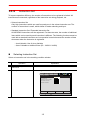
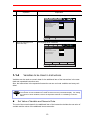
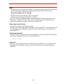
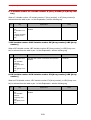
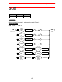
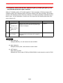
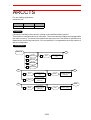
Selecting Instruction Set
Select an instruction set in the teaching condition window.
Operation
1
Select {SETUP} under the
main menu
2
Select {TEACHING COND}
Explanation
The teaching condition window appears.
DATA
EDIT
DISPLAY
UTILITY
TEACHING CONDITION
RECT/CYLINDRICAL
RECT
LANGUAGE LEVEL
SUBSET
INSTRUCTION INPUT LEARNING
VALID
MOVE INSTRUCTION SET
LINE
STEP ONLY CHANGING
PROHIBIT
MRESET
Main Menu
1-2
Short Cut
1.1 About INFORM
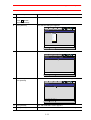
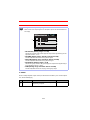
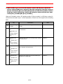
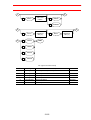
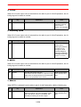
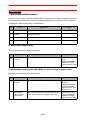
Operation
3
Select “LANGUAGE LEVEL”
Explanation
The instruction set selection dialog box appears.
DATA
EDIT
DISPLAY
UTILITY
TEACHING CONDITION
RECT/CYLINDRICAL
RECT
LANGUAGE LEVEL
MOVE INSTRUCTION SET
SUBSET
STANDARD
EXPANDED
LINE
STEP ONLY CHANGING
PROHIBIT
INSTRUCTION INPUT LEARNING
MRESET
Main Menu
4
Select the language level
(instruction set)
Short Cut
The language level is selected.
DATA
EDIT
DISPLAY
UTILITY
TEACHING CONDITION
RECT/CYLINDRICAL
RECT
LANGUAGE LEVEL
EXPANDED
INSTRUCTION INPUT LEARNING
VALID
MOVE INSTRUCTION SET
LINE
STEP ONLY CHANGING
PROHIBIT
MRESET
Main Menu
1.1.4
Short Cut
Variables to be Used in Instructions
Variables can be used as numeric data for the additional item of the instructions in the standard and expanded instruction sets.
Also, the instructions in the expanded instruction set can use local variables and array variables.
NOTE
The applicable variable differs depending on the additional item.
The number of local variables to be used must be set in the job header display. For setting
the number of local variables, refer to the Operator’s Manual “5.3.5 Editing Local Variables”.
Set Value of Variable and Numeric Data
The unit of the numeric data for the additional item of the instruction decides the set value of
variable and the value of the additional item at execution.
1-3
1.2 Registration of Instructions
< Example >
TIMER tag (T=)
TIMER T=I000
When a variable is used for the numeric data of the TIMER tag, the unit of numeric data is
0.01 seconds.
When 1000 is set for I000, the value when the instruction is executed is 10.00 seconds.
1.2
1.2.1
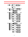
Registration of Instructions
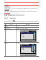
Registration
Press [INFORM LIST]
INFORM
LIST
while the job content window is shown to register instructions.
Operation
Explanation
1
Select {JOB} under the main
menu
2
Select {JOB}
The job content window appears.
3
Press [INFORM LIST]
The job instruction group list dialog box appears.
JOB
EDIT
DISPLAY
JOB CONTENT
JOB NAME : R1S1
CONTROL GROUP : R1+S1
0017
0018
0019
0020
0021
0022
0023
UTILITY
IN/OUT
STEP NO : 004
TOOL : 00
CONTROL
TIMER T=1.00
MOVJ VJ=12.50
MOVJ VJ=50.00
MOVL V=138
MOVL V=138
MOVJ VJ=100.00
DOUT OT#(1) ON
DEVICE
MOTION
ARITH
SHIFT
OTHER
SAME
PRIOR
=>
Main Menu
4
Select the desired instruction
group
Short Cut
The job instruction list dialog box appears.
JOB
EDIT
DISPLAY
JOB CONTENT
JOB NAME : R1S1
CONTROL GROUP : R1+S1
0017
0018
0019
0020
0021
0022
0023
TIMER T=1.00
MOVJ VJ=12.50
MOVJ VJ=50.00
MOVL V=138
MOVL V=138
MOVJ VJ=100.00
DOUT OT#(1) ON
UTILITY
DOUT
STEP NO : 004
TOOL : 00
DIN
IN/OUT
CONTROL
WAIT
DEVICE
PULSE
MOTION
AOUT
ARITH
ARATION
SHIFT
ARATIOF
OTHER
SAME
PRIOR
=>
DOUT OT#(1) ON
Main Menu
1-4
Short Cut
1.2 Registration of Instructions
Operation
Explanation
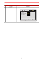
5
Select the desired instruction
The instruction is displayed in the input buffer line.
6
Press [ENTER]
The instruction displayed in the input buffer line is registered in
the job.
Also, if the instruction must be registered during the job, press
[INSERT] before pressing [ENTER]
SUPPLEMENT
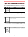
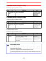
1.2.2
Refer to the Operator’s Manual “5.2 Editing Instructions” for details on editing instructions.
Learning Function
With the learning function, an instruction can be registered with the same additional items as
those previously registered with the instruction.
Validate the learning function to minimize the number of instruction registries.
Set the learning function to valid or invalid in the teaching condition window.
Operation
1
Select {SETUP} under the
main menu
2
Select {TEACHING COND}
Explanation
The teaching condition window appears.
DATA
EDIT
DISPLAY
UTILITY
TEACHING CONDITION
RECT/CYLINDRICAL
RECT
LANGUAGE LEVEL
SUBSET
INSTRUCTION INPUT LEARNING
VALID
MOVE INSTRUCTION SET
LINE
STEP ONLY CHANGING
PROHIBIT
MRESET
Main Menu
3
Move the cursor to “INSTRUCTION INPUT LEARNING”
1-5
Short Cut
1.2 Registration of Instructions
Operation
4
Press [SELECT]
Explanation
The condition “VALID” or “INVALID” is switchable each time
[SELECT] is pressed.
DATA
EDIT
DISPLAY
UTILITY
TEACHING CONDITION
RECT/CYLINDRICAL
RECT
LANGUAGE LEVEL
SUBSET
INSTRUCTION INPUT LEARNING
INVALID
MOVE INSTRUCTION SET
LINE
STEP ONLY CHANGING
PROHIBIT
MRESET
Main Menu
1-6
Short Cut
1.3 Detail Edit Window
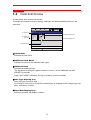
1.3
Detail Edit Window
All instructions have a detail edit window.
The detail edit window is used for adding, modifying, and deleting additional items in the
instruction.
JOB
c Instruction
d Additional
item name
EDIT
DISPLAY
UTILITY
DETAIL EDIT
MOVJ
P-VAR ROBOT
JOINT SPEED
POS LEVEL
T-ROTATION
NWAIT
UNTIL
P000
VJ= 50.00
PL= 1
UNUSED
UNUSED
UNTIL I
f Data type altering icon
g Data edit display icon
e Additional item
=>
MOVJ P000 VJ=50.00 PL=1 UNTIL IN#(1)=ON
Main Menu
Short Cut
cInstructions
Indicates the instruction.
dAdditional Item Name
Indicates the name of the additional item (type).
eAdditional Item
Indicates the additional item.
The tag selection dialog box appears when the cursor is on the additional item and
[SELECT] is pressed.
When “NOT USED” is selected, the tag is omitted (if it can be omitted).
fData Type Altering Icon
Alters the type of numeric data.
For example, if the 50.00 of VJ=50.00 (constant type) is changed to I000 (integer-type variable), it becomes VJ=I000.
gDetail Edit Display Icon
Indicates the detail edit display is shown.
1-7
1.4 Registration of Expression
1.4
Registration of Expression
1.4.1
Expression
With INFORM II, an expression can be added to the SET instruction.
< Example >
SET B000 ( B001 + B002 ) / B003 - ( B004 + B005 ) ∗ B006
Result stored destination
Expression
Register an expression in the DETAIL EDIT window.
SUPPLEMENT
Expressions can be registered only when “STANDARD” or “EXPANDED” has been
selected for the language level (instruction set).
The DETAIL EDIT window for expression is shown below.
EDIT
JOB
DETAIL EDIT
EXPRESSION
c Starting parentheses
DATA01
DATA02
DATA03
DATA04
DATA05
DATA06
DATA07
DISPLAY
( DATA SEL.TYPE )
-((( - 1234567890123
UTILITY
OPERATOR
)))
+
h Operator
g Ending parentheses
f Data type selection icon
d - (negative)
e Data
=>
Main Menu
Short Cut
cStarting parentheses
Move the cursor to the parentheses, and press [SELECT]. Each time [SELECT] is pressed,
three types of parentheses show up in the following order.
(
((
(((
-(
-((
-(((
d - (negative)
Move the cursor to the desired position, and press [SELECT]. Each time [SELECT] is
pressed, the negative is alternately added and omitted and vice versa.
1-8
1.4 Registration of Expression
Data
The data type of the expression is indicated. The following types of data can be registered.
• Constant (byte type, integer type, double-precision type, and real-number type)
• Byte type variable (B, B[], LB, and LB[])
• Integer type variable (I, I[], LI, and LI[])
• Double-precision type variable (D, D[], LD, and LD[])
• Real-number type variable (R, R[], LR, and LR[])
Move the cursor to the desired position, and press [SELECT] to enter the numeric value
input status. Change the numeric value of the constant data and the variable number.
Change the data type by using the Data type selection icon.
Data type selection icon
Change the data type in the following manner.
Move the cursor to the data type to be changed, and press [SELECT]. A dialog box with the
selectable data types is displayed. Move the cursor to the data type to be selected and
press [SELECT].
Ending parentheses
Move the cursor to the parentheses and press [SELECT]. Each time [SELECT] is pressed,
three types of parentheses show up in the following order.
)
))
)))
Operator
Move the cursor to the operator to be changed and press [SELECT]. The operator selection dialog box is displayed. Move the cursor to the operator to be selected and press
[SELECT].
1-9
1.4 Registration of Expression
< Example of the DETAIL EDIT display for expression >
Expression
Result stored destination
SET B000
( B001 +
B002 ) /
B003 -
Data01
Data02
Data03
JOB
DISPLAY
B005 ) *
Data04
Data05
B006
Data06
UTILITY
DETAIL EDIT
EXPRESSION
( DATA SEL.TYPE )
DATA01
DATA02
DATA03
DATA04
DATA05
DATA06
( B001
B002
B003
( B004
B005
B006
=>
OPERATOR
)
)
+
/
+
*
( B001 + B002 ) / B003 - ( B004 + B005 ) * B006
Main Menu
1.4.2
EDIT
( B004 +
Short Cut
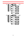
Registration
Operation
1
Select {JOB} under the main
menu
2
Select {JOB}
3
Press [INFORM LIST]
4
Select “ARITH”
5
Select “SET”
6
Press [SELECT]
Explanation
The DETAIL EDIT window for the SET instruction appears.
JOB
EDIT
DISPLAY
DETAIL EDIT
SET
DESTINATION
SOURCE (TOKEN)
=>
B000
1
SET B000 1
Main Menu
1-10
Short Cut
UTILITY
1.4 Registration of Expression
Operation
7
Explanation
Move the cursor to the
button
beside
“SOURCE(TOKEN)”
8
Press [SELECT]
The selection dialog box appears.
JOB
EDIT
DISPLAY
UTILITY
DETAIL EDIT
SET
DESTINATION
SOURCE (TOKEN)
=>
SET B000 1
Main Menu
9
Select “EXPRESS”
Short Cut
The DETAIL EDIT window for expression appears.
JOB
EDIT
DISPLAY
DETAIL EDIT
EXPRESSION
( DATA SEL.TYPE )
DATA01
( 1
=>
UTILITY
OPERATOR
)
1
Main Menu
10 Enter the expression and
press [ENTER]
B000
EXPRESS
CONSTANT
B[]
B
I []
I
D[]
D
R[]
R
EXPRESS
Short Cut
The DETAIL EDIT window for the SET instruction appears.
JOB
EDIT
DISPLAY
UTILITY
DETAIL EDIT
SET
DESTINATION
SOURCE (TOKEN)
=>
B000
EXPRESS
I
SET B000 ( B001 + B002 ) * 5
Main Menu
Short Cut
11 Press [ENTER]
The JOB CONTENT window appears.
12 Press [ENTER]
The SET instruction indicated in the input buffer line is registered.
1-11
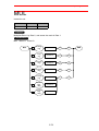
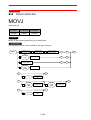
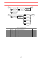
1.5 INFORM Structure
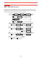
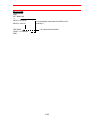
1.5
INFORM Structure
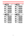
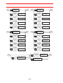
An example of the INFORM structure is shown in the following structure flowchart. The
INFORM structure chart is composed of the structure elements (instruction, tag, and data).
The order of the rows is shown with the numbers and arrows.
1
MOVJ
Robot teaching
point file No.
2
P/LP/P[]/
LP[]
3
Station teaching
point file No.
4
EX/LEX/
EX[]/
LEX[]
5
Base teaching
point file No.
6
Station teaching
point file No.
A
Variable No.
C
B
Variable No.
A
B
7
BP/LBP/
BP[]/
LBP[]
8
Variable No.
EX/LEX/
EX[]/
LEX[]
Variable No.
C
D
9
VJ=
Joint speed(%)
10
PL=
Position level
11
SPDL=
Speed level
D
E
12
MT=
T axis rotation
count
13
E
MTE=
END
14
NWAIT
15
UNTIL
1-12
Station axis
rotation count
1.5 INFORM Structure
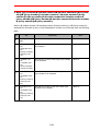
INFORM Structure Elements
INFORM Structure
Element
Explanation
Note
Indicates the instruction.
In this example, the
“MOVJ" instruction is
indicated.
Indicates the tag.
In this example, the
"VJ=" instruction is
indicated.
Indicates the numeric data.
In this example, "Joint
speed" is set with the
unit %.
MOVJ
VJ=
Variable No.(%)
Indicates the end of the instruction.
END
Indicates the connection.
A
A
Indicates the tag order.
1
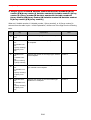
Meaning of INFORM Structure
INFORM Structure
A
P/LP/P[]/
LP[]
A
Variable No.
Meaning
B
This is an indispensable tag.
In this example, it is necessary to add a
tag from [P Variable /LP Variable /P Array
/LP Array].
This is a tag that can be omitted.
In this example, the NWAIT tag can be
omitted.
B
NWAIT
C
D
PL=
Position level
SPDL=
Speed level
1-13
This is a tag that can be selected.
In this example, either PL= tag or
SPDL= tag can be selected.
1.5 INFORM Structure
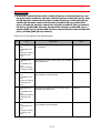
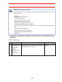
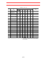
Explanation Table
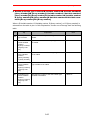
The explanation table in this manual can be described as follows.
No
1
Tag
OT # (Output
number)
Explanation
Specifies the output number signal.
Note
No:1 to 1024
Variable B/I/D/LB/LI/
LD can be used.
• NO.
Indicates the tag number. Corresponds to the number in the INFORM structure.
• Tag
Indicates the surface description of the tag.
• Explanation
Provides an explanation of the tag.
1-14
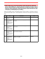
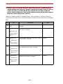
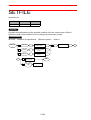
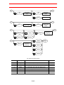
2.1 I/O Instructions
2 INFORM Explanation
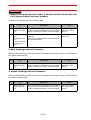
2.1
I/O Instructions
DOUT
Instruction set:
SUBSET
STANDARD
EXPANDED
Available
Available
Available
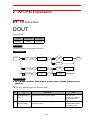
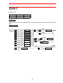
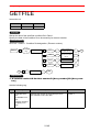
Function
Turns the general output signal on and off.
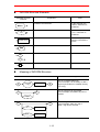
Construction
DOUT
1
OT#
(
)
Output No.
4
B/LB/B[]/
LB[]
5
ON/OFF
2
OG#
(
Output group
No.
)
6
3
OGH#
(
Output group
No.
)
7
B/LB/B[]/
LB[]
END
Variable No.
Variable No.
Byte type
variable
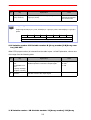
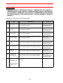
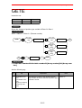
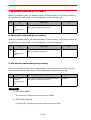
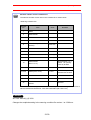
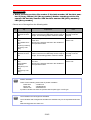
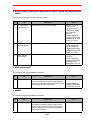
Explanation
1. OT# (Output number) /OG# (Output group number) /OGH# (Output group
number)
Choose one of the tags from the following table.
No
Tag
Explanation
1
OT#(Output number)
Specifies the output number signal.
No:1 to 1024
Variable B/I/D/LB/LI/
LD can be used.
2
OG#(Output
group number)
Specifies the output number group signal
(1group 8 points).
No:1 to 128
Variable B/I/D/LB/LI/
LD can be used.
2-1
Note
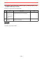
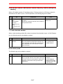
2.1 I/O Instructions
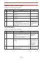
No
3
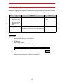
SUPPLEMENT
Tag
Explanation
OGH#(Output
group number)
Note
Specifies the output number group signal
(1group 4 points).
No:1 to 256
Variable B/I/D/LB/LI/
LD can be used.
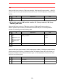
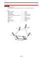
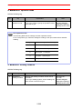
Output signal
Output signal OT#(xx) is 1 point, OGH#(xx) is 1 group 4 points, and OG#(xx) is 1 group 8
points.
OT#(8)
OT#(7) OT#(6)
OGH#(2)
OT#(5)
OT#(4)
OT#(3) OT#(2)
OGH#(1)
OT#(1)
OG#(1)
2. B Variable number /LB Variable number /B [Array number] /LB [Array number] /ON /OFF
When OT# (output number) is selected from the table in part 1 of this Explanation, choose one
of the tags from the following table.
No
Tag
Explanation
4
B Variable number/
LB Variable number /
B [Array number]/
LB [Array number]
The least significant bit of the specified byte type
variable specifies on/off of the output signal.
5
ON/OFF
Specifies on/off of the output signal.
Note
Least significant bit:
0: OFF
1: ON
3. B Variable number / LB Variable number / B [Array number] / LB [Array
2-2
2.1 I/O Instructions
number] / Byte type constant
When OG# (Output group number) or OGH# (Output group number) is selected from the table
in part 1 of this Explanation, choose one of the tags from the following table.
No
Tag
Explanation
Note
6
B Variable number/
LB Variable number/
B [Array number]/
LB [Array number]
Specifies on/off of the output signal by the specified bit value byte type variable.
7
Byte type constant
When the constant byte type is expressed in bit
form, the corresponding on/off output signal is
specified. Specifies on/off of the output signal by
bit value.
bit:
0: OFF
1: ON
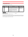
Example
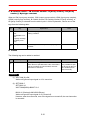
(1) DOUT OT#(12) ON
General output signal no. 12 is turned on.
(2) SET B000 24
DOUT OG#(3) B000
B000=24(Decimal)= 00011000(Binary)
OT#(24)
OT#(23)
OT#(22)
OT#(21)
OT#(20)
OT#(19) OT#(18)
OT#(17)
OG#(3)
ON
General output signals nos. 20 and 21 are turned on.
2-3
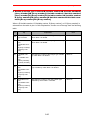
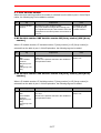
2.1 I/O Instructions
DIN
Instruction set:
SUBSET
STANDARD
EXPANDED
Available
Available
Available
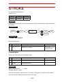
Function
Refers to the byte type variable for the status of the signal.
Construction
DIN
1
B/LB/B[]/
LB[]
Variable No.
2
IN#
(
Input No.
)
3
IG#
(
Input group No.
)
4
OT#
(
Output No.
)
5
OG#
(
Output group
No.
)
6
SIN#
(
Specific
input No.
)
7
SOUT#
(
Specific
output No.
)
8
IGH#
(
Input group No.
)
9
OGH#
(
Output group
No.
)
END
Explanation
1. B Variable Number / LB Variable Number / B [Array Number] / LB [Array
Number]
Add the following tag.
No
Tag
Explanation
1
B Variable Number/
LB Variable Number/
B [Array Number]/
LB [Array Number]
Specifies the number of byte type variable for the
signal.
2-4
Note
2.1 I/O Instructions
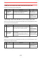
2. IN#(Input number) / IG#(Input group number) / OT#(Output number) /
OG#(Output group number) / SIN#(Specific input number) / SOUT#(Specific output number) / IGH#(Input group number) / OGH#(Output group
number)
Choose one of the tags from the following table.
No
Tag
Explanation
Note
2
IN#(Input number)
Specifies the general input signal number which
shows the signal status.
No:1 to 1024
Variable B/I/D/LB/LI/
LD can be used.
3
IG#(Input group
number)
Specifies the general input group signal number
(1 group 8 points) which shows the signal status.
No:1 to 128
Variable B/I/D/LB/LI/
LD can be used.
4
OT#(Output number)
Specifies the general output signal number
which shows the signal status.
No:1 to 1024
Variable B/I/D/LB/LI/
LD can be used.
5
OG#(Output
group number)
Specifies the general output group signal number (1 group 8 points) which shows the signal
status.
No:1 to 128
Variable B/I/D/LB/LI/
LD can be used.
6
SIN#(Specific
input number)
Specifies the specific input signal number which
shows the signal status.
No:1 to 640
Variable B/I/D/LB/LI/
LD can be used.
7
SOUT#(Specific
output number)
Specifies the specific output signal number
which shows the signal status.
No:1 to 800
Variable B/I/D/LB/LI/
LD can be used.
8
IGH#(Input group
number)
Specifies the general input group number (1
group 4 points) signal which shows the signal
status.
No:1 to 256
Variable B/I/D/LB/LI/
LD can be used.
9
OGH#(Output
group number)
Specifies the number of general output group (1
group 4 points) signal which shows the signal
status.
No:1 to 256
Variable B/I/D/LB/LI/
LD can be used.
SUPPLEMENT
Input signal
Input signal IN#(xx) is 1 point, IGH#(xx) is 1 group 4 points, and IG#(xx) is 1group 8 points.
IN#(8)
IN#(7) IN#(6)
IGH#(2)
IN#(5)
IN#(4)
IG#(1)
2-5
IN#(3) IN#(2)
IGH#(1)
IN#(1)
2.1 I/O Instructions
Example
(1) DIN B016 IN#(12)
The on/off status of general input signal no.12 is shown in byte type variable No.16.
When the general input signal No.12 is on, the status of the general input signal is
B016=1 (decimal)=00000001(binary).
(2) DIN B002 OG#(8)
The on/off status of general output signal nos. 57-64 is shown in byte type variable
No.2.
In the following cases, the status of the general output signal is B002=150 (decimal)= 10010110 (binary).
OT#(64)
OT#(63)
OT#(62)
OT#(61)
OT#(60)
OT#(59)
OT#(58)
OT#(57)
OG#(8)
ON
2-6
2.1 I/O Instructions
WAIT
Instruction set:
SUBSET
STANDARD
EXPANDED
Available
Available
Available
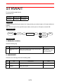
Function
Waits until the status of the external signal or byte type variable is the same as the specified
status.
Construction
WAIT
1
IN#
(
Input No.
)
2
OT#
(
Output No.
)
3
SIN#
(
Specific
input No.
)
4
SOUT#
(
Specific
output No.
)
5
IG#
(
Input group No.
)
13
=
6
OG#
(
Output group
No.
)
14
<>
)
)
7
IGH#
(
Input group No.
(4 Point)
8
OGH#
(
Output group
No. (4 Point)
9
B/LB/B[]/
LB[]
10
=
11
B/LB/B[]/
LB[]
12
ON/OFF
B/LB/B[]/
LB[]
15
Variable No.
Byte type
constant
16
A
END
17
Variable No.
2-7
A
Variable No.
T=
Time (sec)
2.1 I/O Instructions
Explanation
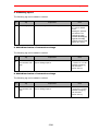
1. IN#(Input number) / OT#(Output number) / SIN#(Specific input number) /
SOUT#(Specific output number) / IG#(Input group number) / OG#(Output
group number) / IGH#(Input group number) / OGH#(Output group number)
/ B Variable Number / LB Variable Number / B [Array Number] / LB [Array
Number]
Choose one of the tags from the following table.
No
Tag
Explanation
Note
1
IN# (Input number)
Specifies the number of the general input signal
for the waiting condition.
No:1 to 1024
Variable B/I/D/LB/LI/
LD can be used.
2
OT# (Output
number)
Specifies the number of the general output signal
for the waiting condition.
No:1 to 1024
Variable B/I/D/LB/LI/
LD can be used.
3
SIN# (Specific
input number)
Specifies the number of the specific input signal
for the waiting condition.
No:1 to 640
Variable B/I/D/LB/LI/
LD can be used.
4
SOUT# (Specific
output number)
Specifies the number of the specific output signal
for the waiting condition.
No:1 to 800
Variable B/I/D/LB/LI/
LD can be used.
5
IG#(Input group
number)
Specifies the number of general input group (1
group 8 points) signal for the waiting condition.
No:1 to 128
Variable B/I/D/LB/LI/
LD can be used.
6
OG#(Output
group number)
Specifies the number of general output group (1
group 8 points) signal for the waiting condition.
No:1 to 128
Variable B/I/D/LB/LI/
LD can be used.
7
IGH#(Input group
number)
Specifies the number of general input group (1
group 4 points) signal for the waiting condition.
No:1 to 256
Variable B/I/D/LB/LI/
LD can be used.
8
OGH#(Output
group number)
Specifies the number of general output group (1
group4 points) signal for the waiting condition.
No:1 to 256
Variable B/I/D/LB/LI/
LD can be used.
9
B Variable number/
LB Variable number/
B [Array number]/
LB [Array number]
Specifies the byte type variable for the waiting
condition.
2-8
2.1 I/O Instructions
2. =
When an IN# (input number), OT# (output number), SIN# (specific input number), or SOUT#
(specific output number) is selected from the table in part 1 of this Explanation, add the following tag.
No
10
Tag
=
Explanation
Note
It is equal.
3. B Variable number /LB Variable number / B [Array number] / LB [Array
number] / ON / OFF
When an IN# (input number), OT#(output number), SIN# (specific input number), or
SOUT# (specific output number) is selected from the table in part 1 of this Explanation,
choose one of the tags from the following table.
No
Tag
Explanation
11
B Variable number/
LB Variable number/
B [Array number]/
LB [Array number]
Specifies byte type variable which becomes a
waiting condition.
12
ON/OFF
Specifies on/off of the waiting condition.
Note
Least significant bit:
0:OFF
1:ON
4. =/<>
When an IG# (input group number), OG# (output group number), IGH# (input group number),
OGH# (output group number), B variable number, LB variable number, B [array number], or
LB [array number] is selected from the table in part 1 of this Explanation, choose one of the
tags from the following table.
No
Tag
Explanation
13
=
It is equal.
14
<>
It is not equal.
2-9
Note
2.1 I/O Instructions
5. B Variable number / LB Variable number / B [Array number] / LB [Array
number] / Byte type constant
When an IG# (input group number), OG# (output group number), IGH# (input group number),
OGH# (output group number), B variable number, LB variable number, B [array number], or
LB [array number] is selected from the table in part 1 of this Explanation, choose one of the
tags from the following table.
No
Tag
Explanation
15
B Variable number/
LB Variable number/
B [Array number]/
LB [Array number]
Specifies byte type variable which becomes a
waiting condition.
16
Byte typeconstant
The waiting condition is specified by byte type
constant.
Note
6. T=time
The following tag can be added or omitted.
No
17
Tag
T=time
Explanation
Note
Specify the waiting time.
When the time specified here ends, if the status
and the condition are not the same, the next
instruction is executed.
Unit: Second
It is possible to specify at time by the I/LI/
I/LI variable (Units:
0.01 seconds).
Example
(1) WAIT IN#(12)=ON
Waits until general input signal no.12 is turned on.
(2) SET B000 5
SET B002 16
WAIT SIN#(B000)=B002 T=3.0
B002=16 (Decimal)=00010000 (Binary)
Waits until specific input signal no.5 is turned off.
However, after three seconds, even if the signal is not turned off, the next instruction
is executed.
2-10
2.1 I/O Instructions
(3) WAIT IGH#(2)<>5
IN#(8)
5 (Decimal)=0101 (Binary)
IN#(7)
IN#(6)
IGH#(2)
IN#(5)
ON
Waits until general input signal nos.5 and 7 are turned off and general input signal
nos. 6 and 8 are turned on.
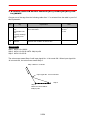
(4) Example of press machine handling.
000 NOP
001 MOVJ VJ=100.0
002 MOVJ VJ=100.0
WAIT IN#(1)=ON
003 MOVJ VJ=100.0
004 MOVJ VJ=100.0
005 MOVJ VJ=100.0
006 MOVJ VJ=100.0
007 MOVJ VJ=100.0
008 MOVJ VJ=100.0
009 END
Press
Machine
Step 1
Step 2
Step 5
Step 3
Step 4
Step 8
Step 6
Step 7
Pallet
The robot cannot be moved to step 3 while the press is closed.
Open/close of the press machine (Open: ON, Shut: OFF) is allocated to general
input signal No.1.
The robot waits until general input signal No.1 turns on at step 2.
2-11
2.1 I/O Instructions
PULSE
Instruction set:
SUBSET
STANDARD
EXPANDED
Available
Available
Available
Function
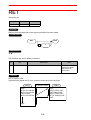
The pulse signal is output to the general output signal only for the specified time.
The PULSE instruction, without waiting for completion of the instruction, executes the next
one.
Construction
PULSE
1
OT#
(
Output No.
)
2
OG#
(
Output group
No.
)
4
3
OGH#
(
Output group
No.
)
5
A
END
6
T=
Time (second)
2-12
A
B/LB/B[]
/LB[]
Byte type
constant
Variable No.
2.1 I/O Instructions
Explanation
1. OT# (output number) / OG# (output group number) / OGH# (output group
number)
Choose one of the tags from the following table.
No
Tag
Explanation
Note
1
OT# (Output No.)
Specifies the number of the signal to which the
pulse signal is output.
No.: 1 to 1024
Variable B/I/D/LB/LI/
LD can be used.
2
OG# (Output
group No.)
Specifies the group number of the signal (1
group 8 points) to which the pulse signal is output.
No.: 1 to 128
Variable B/I/D/LB/LI/
LD can be used.
3
OGH# (Output
group No.)
Specifies the group number of the signal (1
group 4 points) to which the pulse signal is output.
No.: 1 to 256
Variable B/I/D/LB/LI/
LD can be used.
2. B Variable number / LB Variable number / B [Array number] / LB [ Array
number] / Byte type constant
When OG# (output group number) or OGH# (output group number) in the above table is
selected, choose one of the tags from the following table.
No.
Tag
Explanation
4
B Variable number/
LB Variable number/
B [Array Number] /
LB [Array Number]
Specifies the number of the corresponding pulse
output signal when the contents of the specified
byte type variable is expressed in bits.
5
Byte type constant
Specifies the number of the corresponding pulse
output signal when the specified byte type constant is expressed in bits.
2-13
Note
Bit:
0: OFF
1: ON
2.1 I/O Instructions
3. T=Time
The following tag can be added or omitted.
No.
6
Tag
T=Time
Explanation
Note
Specifies the time during which the pulse signal
is output.
The pulse signal is output during the specified
time T.
Units: seconds
Variable I/LI/I[]/LI[]
can be used.
(Units: 0.01 seconds)
When the time is not
specified, the pulse
signal is output during 0.30 seconds.
Example
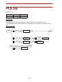
(1) PULSE OT#(128)
The pulse signal is output for 0.30 seconds to general output signal No.128.
Pulse signal
0.3sec
(2) SET B000 5
PULSE OT#(B000) T=1.0
The pulse signal is output for 1.0 seconds to general output signal No.5.
ON
Pulse signal
1.0 sec
OFF
(3) SET B000 24
PULSE OG#(3) B000
B000=24 (Decimal)=00011000 (Binary)
OT#(24)
OT#(23)
OT#(22)
OT#(21)
OT#(20)
OT#(19) OT#(18)
OT#(17)
OG#(3)
ON
The pulse signal is output for 0.30 seconds to the general output signal No.’s 20 and
21.
2-14
2.1 I/O Instructions
AOUT
Instruction set:
SUBSET
STANDARD
EXPANDED
Not available
Available
Available
Function
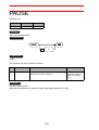
Outputs the set voltage value to the general-purpose analog output port.
Construction
1
AOUT
AO#
(
Analog output
port No.
)
2
Output voltage
value (V)
END
Explanation
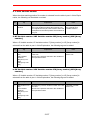
1. AO# (Analog output port number)
Add the following tag.
No
Tag
Explanation
Note
1
AO# (Analog output port number)
Specifies the number of the analog output port to
which the set voltage value is output.
No.: 1 to 40
Variable B/I/D/LB/LI/
LD can be used.
2. Output voltage value
Add the following tag.
No.
2
Tag
Output voltage
value
Explanation
Specifies the output voltage value.
Example
SET I000 1270
AOUT AO#(1) I000
The voltage of 12.7 V is output to the analog output port No. 1.
2-15
Note
Voltage value:
-14.00 to +14.00
Variable I/LI/I[]/LI[]
can be used.
(Units: 0.01 V)
2.1 I/O Instructions
ARATION
Instruction set:
SUBSET
STANDARD
EXPANDED
Not available
Available
Available
Function
Starts the analog output corresponding to the speed.
ARATION is valid during linear interpolation, circular interpolation, and spline interpolation.
ARTION is carried out during playback or FWD operation, but not while operating an axis.
Construction
ARATION
1
AO#
(
Analog output
port No.
)
A
2
BV=
A
Basic voltage
(V)
END
3
V=
Speed at TCP
(mm/sec.)
4
OFV=
Offset voltage
(V)
Explanation
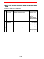
1. AO# (Analog output port number)
Add the following tag.
No.
Tag
1
AO# (Analog output port number)
Explanation
Specifies the number of the analog output port
that outputs the voltage corresponding to the
speed.
Note
No.: 1 to 40
Variable B/I/D/LB/LI/
LD can be used.
2. BV=Basic voltage
The following tag can be added or omitted.
No.
Tag
Explanation
Note
2
BV=Basic voltage
Specifies the voltage to be output when running
at the speed set in part 3 of this Explanation.
Voltage value:
-14.00 to +14.00 V
Variable I/LI/I[]/LI[]
can be used.
(Units: 0.01 V)
2-16
2.1 I/O Instructions
3. V=Basic speed
The following tag can be added or omitted.
No.
3
Tag
V=Basic speed
Explanation
Specifies the speed at which the set voltage
value is output.
Note
Speed: 0.1 to 1500.0
mm/s.
Variable B/I/D/LB/LI/
LD can be used.
(Units: 0.1 mm/s.)
4. OFV=Offset voltage
The following tag can be added or omitted.
No.
Tag
4
OFV=Offset voltage
Explanation
Specifies the analog voltage to be output at the
motion speed “0”.
2-17
Note
Voltage value:
-14.00 to +14.00 V
Variable I/LI/I[]/LI[]
can be used.
(Units: 0.01 V)
2.1 I/O Instructions
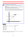
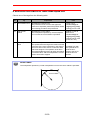
SUPPLEMENT
Analog output function corresponding to the speed
To regulate the thickness of the sealing or paint, etc. when sealing and painting, the
amount of discharged material should be adjusted according to the motion speed of the
manipulator.
The analog output function corresponding to the speed automatically changes the analog
output value according to the manipulator’s motion speed.
ARATION and ARTIOF instructions are used to carry out this function.
On the base of the set value for the ARATION instruction, the output characteristic, which
decides the relation between the motion speed and the analog voltage, is calculated. The
analog output corresponding to speed is output according to this output characteristic.
Analog output
14V
Basic viltage
Offset voltage
0
Basic speed
Motion speed
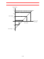
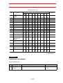
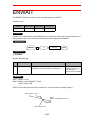
Example
MOVJ VJ=50.00
Output voltage (V)
ARATION AO#(1) BV=7.00 V=150.0 OFV=-10.0
7.00
MOVL V=50.0
-4.33
MOVC V=100.0
1.33
MOVC V=100.0
1.33
MOVC V=100.0
1.33
MOVL V=200.0
12.67
When the basic voltage is 7.00 V at a motion speed of 150.0 mm/sec for the analog output
port number 1, an offset voltage of -10.0 V is output.
2-18
2.1 I/O Instructions
Analog voltage
(V)
14
10
Basic voltage 7
5
0
50
100
150
Basic speed
-5
Offset voltage
-10
2-19
200
Motion speed
(mm/sec)
2.1 I/O Instructions
ARATIOF
Instruction set:
SUBSET
STANDARD
EXPANDED
Not available
Available
Available
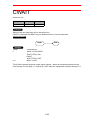
Function
Cancels the analog output corresponding to the speed.
Construction
ARATIOF
1
AO#
(
Analog output
port No.
)
END
Explanation
1. AO# (Analog output port number)
Add the following tag.
No.
Tag
1
AO# (Analog output port number)
Explanation
Specifies the number of the general-purpose
analog output port for which the analog output
corresponding to speed is to be cancelled.
Note
No.: 1 to 40
Variable B/I/D/LB/LI/
LD can be used.
Example
ARATIOF AO#(1)
The analog output corresponding to the speed at the analog output port number 1 is cancelled.
2-20
2.1 I/O Instructions
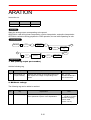
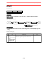
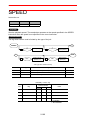
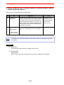
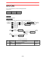
ANTOUT
The ANTOUT instruction can be used only with parameter S2C508.
Instruction set:
SUBSET
STANDARD
EXPANDED
Parameter
Not available
Available
Available
S2C508
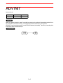
Function
Carries out the anticipation output function to adjust the timing of the signal output.
2-21
2.1 I/O Instructions
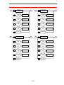
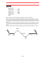
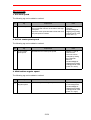
SUPPLEMENT
Anticipation output function
The anticipation output function is a signal output timing adjustment function to advance or
delay the ON/OFF timing of four general-purpose outputs and two general-purpose output
groups. The signal can be output before or after the manipulator reaches the step.
This function corrects work timing errors due to delays in the motions of a peripheral device
and/or the manipulator.
Setting the time to a negative value (-) advances the signal output.
This can be used to correct work timing errors due to delays in the motions of a peripheral
device.
Setting the time to a positive value (+) delays the signal output.
This can be used to correct work timing errors due to delays in the motions of the manipulator.
Advanced signal output
The signal is output before the manipulator reaches the step.
n-1
Step
Instructions
n-1
n
MOVL
MOVL NWAIT
ANTOUT AT#(1) ON
MOVL
n+1
n
n+1
Step
Setting of
general
output
ON
OFF
Set time to advance signal output
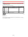
Delayed signal output
The signal is output after the manipulator reaches the step.
n-1
Step
Instructions
n-1
n
MOVL
MOVL NWAIT
ANTOUT AT#(2) ON
MOVL
n+1
n
n+1
Step
Setting of
general
output
ON
OFF
Set time to delay signal output
2-22
2.1 I/O Instructions
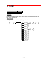
Construction
ANTOUT
1
AT#
(
Anticipation
output No.
)
2
AG#
(
Anticipation
group output
No.
)
3
ON/OFF
4
5
A
B/LB/B[]/
LB[]
A
Variable No.
Byte type
constant
END
6
ANT=
Anticipation
time (s)
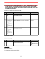
Explanation
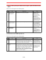
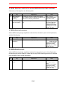
1. AT# (Anticipation output number) / AG# (Anticipation group output number)
Choose one of the tags from the following table.
No.
Tag
Explanation
Note
1
AT# (Anticipation
output number)
Specifies the number of the signal whose timing
is adjusted.
No.: 1 to 4
Variable B/I/D/LB/LI/
LD can be used.
2
AG# (Anticipation
group output
number)
Specifies the group number of the signal whose
timing is adjusted.
No.: 1 or 2
Variable B/I/D/LB/LI/
LD can be used.
2-23
2.1 I/O Instructions
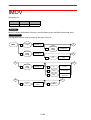
SUPPLEMENT
Settings for the anticipation output signal
Set the number of the output signal for the anticipation output in the ANTICIPATION OUTPUT display.
DATA
EDIT
DISPLAY
UTILITY
ON TIME
OFF TIME
ANTICIPATION OUTPUT
c
<SINGLE>
AT NO. OT OUTPUT
1
010
2
11
12
3
13
4
-0.50
-0.50
-0.50
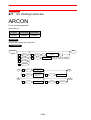
-0.50
<GROUP>
AG NO. OG OUTPUT
1
10
2
11
-0.50
-0.50
-0.80
-0.20
TIME
-0.50
-0.70
e
d
g
f
Main Menu
Short Cut
cOT OUTPUT (Setting range: 1 to 192)
Allocate the number of the general-purpose output whose signal timing is to be
adjusted to AT NO. 1 to 4.
dON TIME (Setting range: -327.68 to 327.67 seconds)
Set the delay/advance time for turning ON the signal.
eOFF TIME (Setting range: -327.68 to 327.67 seconds)
Set the delay/advance time for turning OFF the signal.
fOG OUTPUT (Setting range: 1 to 24)
Allocate the group number of the general-purpose output whose signal timing is
to be adjusted to AG NO. 1 and 2.
gTIME (Setting range: -327.68 to 327.67 seconds)
Set the delay/advance time for carrying out the group output.
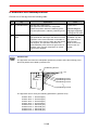
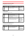
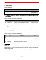
2. ON/OFF
When an AT#(anticipation output number) is selected from the table in part 1 of this Explanation, add the following tag.
No.
3
Tag
ON/OFF
Explanation
Specifies the ON/OFF status of the signal whose
output timing is adjusted.
2-24
Note
2.1 I/O Instructions
3. B Variable number / LB Variable number / B [Array number] / LB [Array
number] / Byte type constant
When an AG#(anticipation group output number) is selected from the table in part 1 of this
Explanation, choose one of the tags from the following table.
No.
Tag
Explanation
Note
4
B Variable number/
LB Variable number/
B [Array number]/
LB [Array number]
Specifies the ON/OFF status of the output signal
corresponding to each bit when the contents of
the specified byte type variable is expressed in
bits.
5
Byte type constant
Specifies the ON/OFF status of the output signal
corresponding to each bit when the contents of
the specified byte type variable is expressed in
bits.
Bit:
0: OFF
1: ON
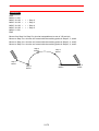
4. ANT=Anticipation time
The following tag can be added or omitted.
No.
Tag
6
ANT=Anticipation
time
Explanation
Note
Specifies the delay/advance time for the output
signal timing.
Units: seconds
Variable I/LI/I[]/LI[]
can be used. (Units:
0.01 seconds)
When the time is not
specified, the time
set in the signal timing adjustment file is
applied.
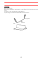
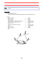
Example
Step
n-1
n
n+1
Instructions
MOVL V=100
MOVL V=100 NWAIT
ANTOUT AT#(1) ON
MOVL V=100
DATA
EDIT
DISPLAY
UTILITY
ON TIME
OFF TIME
ANTICIPATION OUTPUT
<SINGLE>
AT NO. OT OUTPUT
1
010
2
11
---3
---4
Turns ON the general-purpose signal number
10 0.5 seconds before the manipulator
reaches the step.
(Advanced signal output)
<GROUP>
AG NO. OG OUTPUT
1
--2
---
Main Menu
2-25
Short Cut
0.00
0.00
0.00
0.00
TIME
0.00
0.00
-0.50
-0.50
0.00
0.00
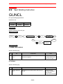
2.2 Control Instruction
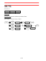
2.2
Control Instruction
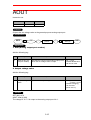
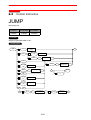
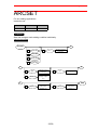
JUMP
Instruction set:
SUBSET
STANDARD
EXPANDED
Available
Available
Available
Function
Jumps to specified label or job.
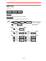
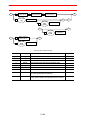
Construction
JUMP
Label character
string
1
*
2
LABEL:
10
B/LB/B[]/
LB[]
11
IG#
3
JOB:
4
B/LB/B[]/
LB[]
5
IG#
6
QUE
7
I/LI/I[]
/LI[]
Variable No.
8
D/LD/D[]/
LD[]
Variable No.
B
B
A
Variable No.
(
)
Input group No.
13
UF#
(
Variable No.
(
Input group No.
)
User
coordinate No.
A
)
END
14
IF
C
9
JET#
(
Job registration
table No.
2-26
)
12
ENTRY=
Registration
No.
C
2.2 Control Instruction
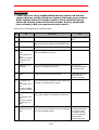
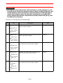
Explanation
1. *Label character string /LABEL:/JOB:/B Variable number /LB Variable
number /B [Array number] /LB [Array number] /IG# (Input group number) /
QUE/I Variable number/LI Variable number/I [Array number]/LI [Array
number]/D Variable number/LD Variable number/ D [Array number]/LD
[Array number]/ JET# (Job registration table number)
Choose one of the tags from the following table.
No
Tag
Explanation
Note
1
*Label strings
Specifies the label string.
2
LABEL:
The numerical value specified by byte type variable or input group number is considered a label.
3
JOB:
Specifies the job.
4
B Variable number/
LB Variable number/
B [Array number]/
LB [Array number]
The numerical value specified by byte type variable is considered to be a job.
5
IG#(Input group
number)
The numerical value specified by the input group
number is considered to be a job.
No:1 to 128
Variable B/I/D/LB/LI/
LD can be used.
6
QUE
Jumps to the job stored in the queue.
Available only in the
queue function
(option: S2C503).
7
I Variable number/
LI Variable number/
I [Array number]/
LI [Array number]
The numerical value specified by the integer type
variable is considered to be the job.
8
D Variable number/
LD Variable number/
D [Array number]/
LD [Array number]
The numerical value specified by the double-precision type variable is considered to be the job.
9
JET# (Job registration table number)
Specifies the job registration table number.
The job of the jump destination can be registered
in the job registration table.
2-27
String: eight characters
No.: 1 to 3
Variable B/I/D/LB/LI/
LD can be used.
Available only with
the job registration
table function
(option: S2C345)
2.2 Control Instruction
2. B Variable number / LB Variable number / B [Array number] / LB [Array
number] / IG# (Input group number)
When a LABEL: is selected from the table in part 1 of this Explanation, choose one of the tags
from the following table.
No
Tag
Explanation
10
B Variable number/
LB Variable number/
B [Array number]/
LB [Array number]
Specifies the byte type variable in which the
numerical value for the label is set.
11
IG#(Input group
number)
Specifies the input group number of the numerical value for the label.
Note
No:1 to 128
B/I/D/LB/LI/LD Variable can be used.
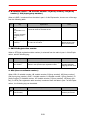
3. ENTRY=Registration number
When a JET#(job registration table number) is selected from the table in part 1 of this Explanation, add the following tag.
No.
Tag
Explanation
Note
12
ENTRY=Registration number
Specifies the registration number of the job registered in the specified job registration table.
No.: 1 to 1024
Variable B/B[]/LB/
LB[]/I/I[] can be used.
4. UF# (User coordinate number)
When JOB:, B variable number, LB variable number, B [Array number], LB [Array number],
IG# (Input group number), QUE, I Variable number, LI Variable number, I [Array number], LI
[Array number], D Variable number, LD Variable number, D [Array number], LD [Array number], or JET# (Job registration table number) is selected from the table in part 1 of this Explanation, the following tag can be added.
No
Tag
13
UF# (User coordinate number)
Explanation
Specifies the coordinates of the job.
2-28
Note
Available only in the
relative job function.
2.2 Control Instruction
5. IF
The following tag can be added or omitted.
No
14
Tag
IF
Explanation
Specifies the IF instruction.
Note
Refer to " 2.6
Instruction Which
Adheres to an
Instruction ".
Example
(1) JUMP *1
Jumps to *1.
(2) JUMP JOB:TEST1 UF#(2)
Jumps to the job named TEST1. TEST1 works in user coordinate system No.2.
(3) SET B000 1
JUMP B000 IF IN#(14)=ON
If input signal no.14 is on, it jumps to job “1”.
2-29
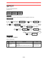
2.2 Control Instruction
CALL
Instruction set:
SUBSET
STANDARD
EXPANDED
Available
Available
Available
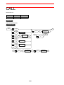
Function
Calls the specified job.
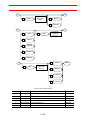
Construction
CALL
1
JOB:
2
B/LB/B[]/
LB[]
3
IG#
4
QUE
5
I/LI/I[]
/LI[]
Variable No.
6
D/LD/D[]/
LD[]
Variable No.
A
9
UF#
User
coordinate No.
(
Variable No.
A
(
Input group No.
END
)
10
B
B
)
IF
C
7
JET#
(
Job registration
table No.
2-30
)
8
ENTRY=
Registration
No.
C
2.2 Control Instruction
Explanation
1. JOB: / B Variable number / LB Variable number / B [Array number] /
LB [Array number] / IG#(Input group number) / QUE/I Variable number/LI
Variable number/I [Array number]/LI [Array number]/D Variable number/LD
Variable number/ D [Array number]/LD [Array number]/ JET# (Job registration table number)
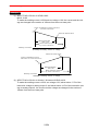
Choose one of the tags from the following table.
No
Tag
Explanation
Note
1
JOB:
Specifies any job to be called.
2
B Variable number/
LB Variable number/
B [Array number]/
LB [Array number]
The numerical value specified in the byte type
variable is considered to be the call job.
3
IG# (Input group
number)
The numerical value specified in the input group
number is considered to be the call job.
No:1 to 128
Variable B/I/D/LB/LI/
LD can be used.
4
QUE
The job stored in the queue is called.
Available only in the
queue function
(option: S2C503).
5
I Variable number/
LI Variable number/
I [Array number]/
LI [Array number]
The numerical value specified by the integer type
variable is considered to be the call job.
6
D Variable number/
LD Variable number/
D [Array number]/
LD [Array number]
The numerical value specified by the double-precision type variable is considered to be the call
job.
7
JET# (Job registration table number)
Specifies the table number of the job registration.
The call job can be registered in the job registration table.
2-31
No.: 1 to 3
Variable B/I/D/LB/LI/
LD can be used.
Available only in the
job registration table
function (option:
S2C345)
2.2 Control Instruction
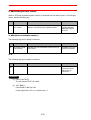
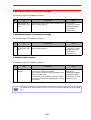
2. ENTRY=Registration number
When a JET#(job registration table number) is selected from the table in part 1 of this Explanation, add the following tag.
No.
Tag
Explanation
8
ENTRY=Registration number
Specifies the registration number of the job registered in the specified job registration table.
Note
No.: 1 to 1024
Variable B/B[]/LB/
LB[]/I/I[]/LI/LI[] can
be used.
3. UF# (User coordinate number)
The following tag can be added or omitted.
No
Tag
9
UF# (User coordinate number)
Explanation
Specifies the user coordinate system of the job
to be called.
Note
Available only in the
relative job function.
4. IF
The following tag can be added or omitted.
No
10
Tag
IF
Explanation
Specifies the IF instruction.
Example
(1) CALL JOB:TEST1
The job named TEST1 is called.
(2) SET B000 1
CALL B000 IF IN#(14)=ON
If input signal No.14 is on, it calls the job “1”.
2-32
Note
Refer to " 2.6
Instruction Which
Adheres to an
Instruction ".
2.2 Control Instruction
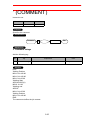
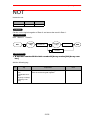
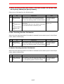
TIMER
Instruction set:
SUBSET
STANDARD
EXPANDED
Available
Available
Available
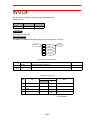
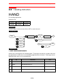
Function
Stops for the specified time.
Construction
TIMER
1
T=
Time (s)
END
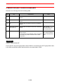
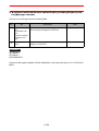
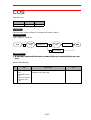
Explanation
1. T=timer
Add the following tag.
No
1
Tag
T=timer
Explanation
Specifies the stopping time.
Example
(1) TIMER T=12.50
Stops for 12.5 seconds.
(2) SET I002 5
TIMER T=I002
Stops for 0.05 seconds.
2-33
Note
Unit: Second
Variable I/LI/I[]/LI[]
can be used.
(Units: 0.01 seconds)
2.2 Control Instruction
* (LABEL)
Instruction set:
SUBSET
STANDARD
EXPANDED
Available
Available
Available
Function
Specifies the label for the jump.
Construction
LABEL
1
*
Label strings
END
Explanation
1. *Label strings
Add the following tag.
No
1
Tag
*Label strings
Explanation
Specifies the label strings.
Note
String: 8 characters
Example
NOP
*1
JUMP JOB:1 IF IN#(1)=ON
Repeat
JUMP JOB:2 IF IN#(2)=ON
JUMP *1
END
IF general input signal No.1 and No.2 are off, if loops infinitely between “*1" and “JUMP *1".
NOTE The label is effective only in the same job. It does not jump to the same label in other jobs.
2-34
2.2 Control Instruction
’ (COMMENT)
Instruction set:
SUBSET
STANDARD
EXPANDED
Available
Available
Available
Function
Specifies the comment.
Construction
COMMENT
1
'
Comment strings
END
Explanation
1. 'Comment strings
Add the following tag.
No
Tag
1
'Comment strings
Explanation
Specifies the comment.
Example
NOP
'Waiting Position
MOVJ VJ=100.00
MOVJ VJ=100.00
MOVJ VJ=25.00
'Welding Start
ARCON ASF#(1)
MOVL V=138
'Welding end
ARCOF
MOVJ VJ=25.00
'Waiting Position
MOVJ VJ=100.00
END
The comment clarifies the job content.
2-35
Note
String: 32 characters
2.2 Control Instruction
RET
Instruction set:
SUBSET
STANDARD
EXPANDED
Available
Available
Available
Function
Returns from the called job to the original job which has been called.
Construction
RET
END
1
IF
Explanation
1. IF
The following tag can be added or omitted.
No
1
Tag
IF
Explanation
Note
Specifies the IF instruction.
Refer to " 2.6
Instruction Which
Adheres to an
Instruction ".
Example
RET IF IN#(12)=ON
If general input signal No.12 is on, it returns to the job of the call origin.
JOB:1
Execution order
NOP
MOVJ VJ=100.00
MOVJ VJ=100.00
CALL JOB:2
MOVJ VJ=100.00
JOB:2
NOP
DOUT OT#(1) ON
WAIT IN#(1)=ON
DOUT OT#(1) OFF
RET IF IN#(12)=ON
END
END
2-36
2.2 Control Instruction
NOP
Instruction set:
SUBSET
STANDARD
EXPANDED
Not available
Available
Available
Function
Carries out no operation.
Construction
NOP
END
Example
NOP
END
2-37
2.2 Control Instruction
PAUSE
Instruction set:
SUBSET
STANDARD
EXPANDED
Not available
Available
Available
Function
Stops the job temporarily.
Construction
PAUSE
END
1
IF
Explanation
1. IF
The following tag can be added or omitted.
No.
1
Tag
IF
Explanation
Specifies an IF statement. An IF instruction
states the execution conditions.
Note
Refer to IF of “2.6
Instructions Which
Adheres to Instruction”.
Example
PAUSE IF IN#(12)=ON
Stops the job temporarily if general-purpose input signal number 12 is ON.
2-38
2.2 Control Instruction
CWAIT
Instruction set:
SUBSET
STANDARD
EXPANDED
Not available
Available
Available
Function
Waits for the next instruction line to be carried out.
CWAIT is used with the NWAIT tag, an additional item of a move instruction.
Construction
CWAIT
END
Example
<Step>
n
n+1
<Instructions>
MOVL V=100 NWAIT
DOUT OT#(1) ON
CWAIT
DOUT OT#(1) OFF
MOVL V=100
Turns ON the general-purpose output signal number 1 when the manipulator starts moving
from the step n to the step n+1, and turns it OFF when the manipulator reaches the step n+1.
2-39
2.2 Control Instruction
ADVINIT
Instruction set:
SUBSET
STANDARD
EXPANDED
Not available
Not available
Available
Function
When the same variable is used for multiple systems in the optional independent control function, ADVINIT controls the timing to change the variable data among the systems.
ADVINIT is an instruction used to control NX100 internal processing, therefore, executing this
instruction does not affect the job.
Construction
ADVINIT
END
2-40
2.2 Control Instruction
ADVSTOP
Instruction set:
SUBSET
STANDARD
EXPANDED
Not available
Available
Available
Function
When the same variable is used for multiple systems in the optional independent control function, ADVSTOP controls the access timing of the variable data among the systems.
ADVSTOP is an instruction used to control NX100 internal processing, therefore, executing
this instruction does not affect the job.
Construction
ADVSTOP
END
2-41
2.3 Operating Instruction
2.3
Operating Instruction
CLEAR
Instruction set:
SUBSET
STANDARD
EXPANDED
Available
Available
Available
Function
In Data 1, the variable content from the specified number on, is cleared to 0 only by the
amount specified in Data 2.
Construction
CLEAR
<Data 1>
CLEAR
<Data 2>
1
B/LB/B[]/
LB[]
Variable No.
8
9
2
I/LI/I[]
/LI[]
Variable No.
3
D/LD/D[]/
LD[]
Variable No.
4
R/LR/R[]/
LR[]
Variable No.
5
STACK
6
QUE
7
MPF
2-42
Byte type
constant
ALL
END
2.3 Operating Instruction
Explanation
1. B Variable number /LB Variable number /B [Array number] /LB [Array number] /I Variable number /LI Variable number /I [Array number] /LI [Array
number] /D Variable number /LD Variable number /D [Array number] /LD
[Array number] /R Variable number/ LR Variable number /R [Array number]
/LR [Array number] /STACK/QUE/MPF
Choose one of the tags from the following table.
No
Tag
Explanation
1
B Variable number/
LB Variable number/
B [Array number]/
LB [Array number]
Specifies the number of the byte type variable to
be cleared.
< Data 1 >
2
I Variable number/
LI Variable number/
I [Array number]/
LI [Array number]
Specifies the number of the integer type variable
to be cleared.
< Data 1 >
3
D Variable number/
LD Variable number/
D [Array number]/
LD [Array number]
Specifies the number of the double precision
type variable to be cleared.
< Data 1 >
4
R Variable number/
LR Variable number/
R [Array number]/
LR [Array number]
Specifies the number of the real type variable to
be cleared.
< Data 1 >
5
STACK
There are eight stacks, and they store the called
position.
< Data 1 >
6
QUE
Clears all the job queues.
<Data 1>
Available only with
the job queue function (option: S2C503)
7
MPF
Clears all the contents of the memo play file.
<Data 1>
Available only with
the optional memo
play function.
2-43
Note
2.3 Operating Instruction
SUPPLEMENT
About the job call stack
There are eight stacks, and they store the called position.
Stack level 1
Stack level 2
Stack level 3
Stack level 4
Job call
Job A
Job call
Job B
Job call
Job C
Return
Job call
Job D
Return
Return
2. Byte type constant /ALL
When a B Variable number, LB Variable number, B [Array number], LB [Array number], I Variable number, LI Variable number, I [Array number], LI [Array number], D Variable number, LD
Variable number, D [Array number], LD [Array number], R Variable number, LR Variable number, R [Array number], or LR [Array number] is selected from the table in part 1 of this Explanation, choose one of the tags from the following table.
No
Tag
Explanation
8
Byte type constant
Specifies the number cleared starting from the
number of the specified variable.
9
ALL
All variables starting from the number of the
specified variable are cleared.
Note
Example
(1) CLEAR B003 10
The content of the variables from B003 to B0012 are cleared to 0.
(2) CLEAR D010 ALL
The content of all the double precision type variables is cleared to 0 starting from
D010.
(3) CLEAR STACK
All the job call stacks are cleared.
2-44
2.3 Operating Instruction
JOB:1
NOP
MOVJ VJ=100.00
JOB:2
JOB:3
NOP
MOVJ VJ=100.00
NOP
MOVJ VJ=100.00
JOB:4
NOP
CLEAR STACK
CALL JOB:2
CALL JOB:3
JUMP JOB:1
RET
END
END
END
JUMP JOB:4
END
JOB:2
JOB:1
JOB:1
Cleared
2-45
JOB:1
Cleared all
2.3 Operating Instruction
INC
Instruction set:
SUBSET
STANDARD
EXPANDED
Available
Available
Available
Function
Adds one to the content of the specified variable.
Construction
INC
1
B/LB/B[]/
LB[]
Variable No.
2
I/LI/
I[]/LI[]
Variable No.
3
D/LD/D[]/
LD[]
Variable No.
2-46
END
2.3 Operating Instruction
Explanation
1. B Variable number /LB Variable number /B [Array number] /LB [Array number] /I Variable number/ LI Variable number /I [Array number] /LI [Array
number] /D Variable number/ LD Variable number /D [Array number] /LD
[Array number]
Choose one of the tags from the following table.
No
Tag
Explanation
1
B Variable number/
LB Variable number/
B [Array number]/
LB [Array number]
Specifies the number of the byte type variable.
2
I Variable number/
LI Variable number/
I [Array number]/
LI [Array number]
Specifies the number of the integer type variable.
3
D Variable number/
LD Variable number/
D [Array number]/
LD [Array number]
Specifies the number of the double precision
type variable.
Note
Example
NOP
SET B000 0
*1
MOVJ VJ=100.00
MOVJ VJ=50.00
INC B000
JUMP *1 IF B000<200
END
1 is repeatedly added to B000 until it reaches 200.
1 is added to B000.
2-47
2.3 Operating Instruction
DEC
Instruction set:
SUBSET
STANDARD
EXPANDED
Not available
Available
Available
Function
Subtracts 1 from a specified variable.
Construction
DEC
1
B/LB/B[]/
LB[]
Variable No.
2
I/LI/I[]
/LI[]
Variable No.
3
D/LD/D[]/
LD[]
Variable No.
END
Explanation
1. B Variable number/LB Variable number/B [Array number]/LB [Array number]/I Variable number/LI Variable number/I [Array number]/LI [Array number]/ D Variable number/LD Variable number/D [Array number]/LD [Array
number]
Choose one of the tags from the following table.
No.
Tag
Explanation
1
B Variable number/
LB Variable number/
B [Array number]/
LB [Array number]
Specifies the number of the byte type variable
from which 1 is subtracted.
2
I Variable number/
LI Variable number/
I [Array number]/
LI [Array number]
Specifies the number of the integer type variable
from which 1 is subtracted.
3
D Variable number/
LD Variable number/
D [Array number]/
LD [Array number]
Specifies the number of the double-precision
type variable from which 1 is subtracted.
2-48
Note
2.3 Operating Instruction
Example
NOP
SET B000 200
*1
MOVJ VJ=100.00
MOVJ VJ=50.00
DEC B000
JUMP *1 IF B000=0
END
1 is repeatedly subtracted from B000 until it
reaches 0.
1 is subtracted from B000.
2-49
2.3 Operating Instruction
SET
Instruction set:
SUBSET
STANDARD
EXPANDED
Available
Available
Available
Function
Sets Data 2 to Data 1.
Construction
SET
<Data 1>
SET
<Data 2>
1
B/LB/B[]/
LB[]
Variable No.
A
B
2
I/LI/
I[]/LI[]
Variable No.
C
D
3
D/LD/D[]/
LD[]
Variable No.
E
F
4
R/LR/R[]/
LR[]
Variable No.
G
H
5
P/LP/P[]/
LP[]
Variable No.
6
BP/LBP/
BP[]/
LBP[]
7
EX/LEX/
EX[]/
LEX[]
END
32
P/LP/P[]/
LP[]
Variable No.
Variable No.
33
BP/LBP/
BP[]/
LBP[]
Variable No.
Variable No.
34
EX/LEX/
EX[]/
LEX[]
Variable No.
2-50
2.3 Operating Instruction
A
E
8
Byte type
constant
B
C
14
Integer type
constant
D
9
B/LB/B[]/
LB[]
Variable No.
15
B/LB/B[]/
LB[]
Variable No.
10
I/LI/I[]
/LI[]
Variable No.
16
I/LI/I[]
/LI[]
Variable No.
11
D/LD/D[]/
LD[]
Variable No.
17
D/LD/D[]/
LD[]
Variable No.
12
R/LR/R[]/
LR[]
Variable No.
18
R/LR/R[]/
LR[]
Variable No.
13
Expression
19
Expression
26
Real-number
type constant
20
Double-precision
type constant
F
G
H
21
B/LB/B[]/
LB[]
Variable No.
27
B/LB/B[]/
LB[]
Variable No.
22
I/LI/I[]
/LI[]
Variable No.
28
I/LI/I[]
/LI[]
Variable No.
23
D/LD/D[]/
LD[]
Variable No.
29
D/LD/D[]/
LD[]
Variable No.
24
R/LR/R[]/
LR[]
Variable No.
30
R/LR/R[]/
LR[]
Variable No.
25
Expression
31
Expression
2-51
2.3 Operating Instruction
Explanation
1. B Variable number /LB Variable number /B [Array number] /LB [Array number] /I Variable number /LI Variable number /I [Array number] /LI [Array
number] /D Variable number /LD Variable number /D [Array number] /LD
[Array number] /R Variable number /LR Variable number /R [Array number]
/LR [Array number] /P Variable number /LP Variable number /P [Array number] /LP [Array number] /BP Variable number /LBP Variable number /BP
[Array number] /LBP [Array number] /EX Variable number /LEX Variable
number /EX [Array number] /LEX [Array number]
Choose one of the tags from the following table.
No
Tag
Explanation
1
B Variable number/
LB Variable number/
Ba[Array number]/
LBa[Array number]
Specifies the number of the byte type variable to
which data is set.
< Data1>
2
I Variable number/
LI Variable number/
I [Array number]/
LI [Array number]
Specifies the number of the integer type variable
to which data is set.
< Data 1>
3
D Variable number/
LD Variable number/
Da[Array number]/
LDa[Array number]
Specifies the number of the double precision
type variable to which data is set.
< Data 1>
4
R Variable number/
LR Variable number/
R [Array number]/
LR [Array number]
Specifies the number of the real type variable to
which data is set.
< Data 1>
5
P Variable number/
LP Variable number/
P [Array number]/
LP [Array number]
Specifies the number of the robot axis positional
variable to which data is set.
< Data 1>
2-52
Note
2.3 Operating Instruction
No
Tag
Explanation
6
BP Variable number/
LBP Variable
number/
BP [Array number]/
LBP [Array number]
Specifies the number of the base axis positional
variable to which data is set.
< Data 1>
7
EX Variable number/
LEX Variable
number/
EX [Array number]/
LEX [Array number]
Specifies the number of the station axis positional variable to which data is set.
< Data 1>
2-53
Note
2.3 Operating Instruction
2. Byte type constant /B Variable number /LB Variable number /B [Array
number] /LB [Array number] /I Variable number /LI Variable number /I
[Array number] /LI [Array number] /D Variable number /LD Variable number /D [Array number] /LD [Array number] /R Variable number /LR Variable
number /R [Array number] /LR [Array number]/Expression
When a B Variable number, LB Variable number, B [Array number], or LB [Array number] is
selected from the table part 1 of this Explanation, choose one of the tags from the following
table.
No
Tag
Explanation
Note
8
Byte type constant
Specifies the byte type constant.
< Data 2>
9
B Variable number/
LB Variable number/
B [Array number]/
LB [Array number]
Specifies the number of the byte type variable.
< Data 2>
10
I Variable number/
LI Variable number/
I [Array number]/
LI [Array number]
Specifies the number of the integer type variable.
< Data 2>
11
D Variable number/
LD Variable number/
D [Array number]/
LD [Array number]
Specifies the number of the double precision
type variable.
< Data 2>
12
R Variable number/
LR Variable number/
R [Array number]/
LR [Array number]
Specifies the number of the real type variable.
< Data 2>
13
Expression
Specifies the expression.
<Data 2>
For details of setting
the expression, refer
to “1.4 Registration
of Expression”.
2-54
2.3 Operating Instruction
3. Integer type constant /B Variable number /LB Variable number /B [Array
number] /LB [Array number] /I Variable number /LI Variable number /I
[Array number] /LI [Array number] /D Variable number /LD Variable number /D [Array number] /LD [Array number] /R Variable number /LR Variable
number /R [Array number] /LR [Array number]/Expression
When an I Variable number, LI Variable number, I [Array number], or LI [Array number] is
selected from the table in part 1 of this Explanation, choose one of the tags from the following
table.
No
Tag
Explanation
14
Integer type constant
Specifies the integer type constant.
< Data 2>
15
B Variable number/
LB Variable number/
B [Array number]/
LB [Array number]
Specifies the number of the byte type variable.
< Data 2>
16
I Variable number/
LI Variable number/
I [Array number]/
LI [Array number]
Specifies the number of the integer type variable.
< Data 2>
17
D Variable number/
LD Variable number/
D [Array number]/
LD [Array number]
Specifies the number of the double precision
type variable.
< Data 2>
18
R Variable number/
LR Variable number/
R [Array number]/
LR [Array number]
Specifies the number of the real type variable.
< Data 2>
19
Expression
Specifies the expression.
<Data 2>
For details of setting
the expression, refer
to “1.4 Registration
of Expression”.
2-55
Note
2.3 Operating Instruction
4. Double precision type constant /B Variable number /LB Variable number /
B [Array number] /LB [Array number] /I Variable number /LI Variable number /I [Array number] /LI [Array number] /D Variable number /LD Variable
number /D [Array number] /LD [Array number] /R Variable number /LR Variable number /R [Array number] /LR [Array number]/Expression
When a D Variable number, LD Variable number, D [Array number], or LD [Array number] is
selected from the table in part 1 of this Explanation, choose one of the tags from the following
table.
No
Tag
Explanation
20
Double precision
type constant
Specifies the double precision type constant.
< Data 2>
21
B Variable number/
LB Variable number/
B [Array number]/
LB [Array number]
Specifies the number of the byte type variable.
< Data 2>
22
I Variable number/
LI Variable number/
I [Array number]/
LI [Array number]
Specifies the number of the integer type variable.
< Data 2>
23
D Variable number/
LD Variable number/
D [Array number]/
LD [Array number]
Specifies the number of the double precision
type variable.
< Data 2>
24
R Variable number/
LR Variable number/
R [Array number]/
LR [Array number]
Specifies the number of the real type variable.
< Data 2>
25
Expression
Specifies the expression.
<Data 2>
For details of setting
the expression, refer
to “1.4 Registration
of Expression”.
2-56
Note
2.3 Operating Instruction
5. Real type constant /B Variable number /LB Variable number /B [Array
number] /LB [Array number] /I Variable number /LI Variable number /I
[Array number] /LI [Array number] /D Variable number /LD Variable number /D [Array number] /LD [Array number] /R Variable number /LR Variable
number /R [Array number] /LR [Array number]/Expression
When an R Variable number, LR Variable number, R [Array number], or LR [Array number] is
selected from the table in part 1 of this Explanation, choose one of the tags from the following
table.
No
Tag
Explanation
Note
26
Real type constant
Specifies the real type constant.
< Data 2>
27
B Variable number/
LB Variable number/
B [Array number]/
LB [Array number]
Specifies the number of the byte type variable.
< Data2>
28
I Variable number/
LI Variable numb
er/
I[Array number]/
LI [Array number]
Specifies the number of the integer type variable.
< Data 2>
29
D Variable number/
LD Variable number/
D [Array number]/
LD [Array number]
Specifies the number of the double precision
type variable.
< Data 2>
30
R Variable number/
LR Variable number/
R [Array number]/
LR [Array number]
Specifies the number of the real type variable.
< Data 2>
31
Expression
Specifies the expression.
<Data 2>
For details of setting
the expression, refer
to “1.4 Registration
of Expression”.
2-57
2.3 Operating Instruction
6. P Variable number /LP Variable number /P [Array number] /LP [Array number]
When a P Variable number, LP Variable number, P [Array number], or LP [Array number] is
selected from the table in part 1 of this Explanation, add the following tag.
No
Tag
32
P Variable number/
LP Variable number/
P [Array number]/
LP [Array number]
Explanation
Specifies the number of the robot axis position
variable.
Note
< Data 2>
7. BP Variable number /LBP Variable number /BP [Array number] /LBP [Array
number]
When a BP Variable number, LBP Variable number, BP [Array number], or LBP [Array number] is selected from the table in part 1 of this Explanation, add the following tag.
No
Tag
33
BP Variable number/
LBP Variable
number/
BP [Array number]/
LBP [[Array number]
Explanation
Specifies the number of the base axis position
variable.
Note
< Data 2>
8. EX Variable number /LEX Variable number /EX [Array number] /LEX [Array
number]
When an EX Variable number, LEX Variable number, EX [Array number], or LEX [Array number] is selected from the table in part 1 of this Explanation, add the following tag.
No
Tag
Explanation
34
EX Variable number/
LEX Variable
number/
EX [Array number]/
LEX [Array number]
Specifies the number of the station axis position
variable.
2-58
Note
< Data 2>
2.3 Operating Instruction
Example
(1) SET B000 0
0 is set in B000.
(2) SET P000 P001
The content of P001 is set in P000.
2-59
2.3 Operating Instruction
ADD
Instruction set:
SUBSET
STANDARD
EXPANDED
Not available
Available
Available
Function
Adds Data 1 and Data 2, and stores the result in Data 1.
Construction
Add <Data 1> <Data 2>
ADD
1
B/LB/B[]/
LB[]
Variable No.
A
B
2
I/LI/I[]
/LI[]
Variable No.
C
D
3
D/LD/D[]/
LD[]
Variable No.
E
F
4
R/LR/R[]/
LR[]
Variable No.
G
H
5
P/LP/P[]/
LP[]
Variable No.
28
P/LP/P[]/
LP[]
Variable No.
6
BP/LBP/
BP[]/
LBP[]
Variable No.
29
BP/LBP/
BP[]/
LBP[]
Variable No.
7
EX/LEX/
EX[]/
LEX[]
Variable No.
30
EX/LEX/
EX[]/
LEX[]
Variable No.
2-60
END
2.3 Operating Instruction
A
E
8
Byte type
constant
B
C
13
Integer type
constant
D
9
B/LB/B[]/
LB[]
Variable No.
14
B/LB/B[]/
LB[]
Variable No.
10
I/LI/I[]
/LI[]
Variable No.
15
I/LI/I[]
/LI[]
Variable No.
11
D/LD/D[]/
LD[]
Variable No.
16
D/LD/D[]/
LD[]
Variable No.
12
R/LR/R[]/
LR[]
Variable No.
17
R/LR/R[]/
LR[]
Variable No.
23
Real-number
type constant
18
Double-precision
type constant
F
G
H
19
B/LB/B[]/
LB[]
Variable No.
24
B/LB/B[]/
LB[]
Variable No.
20
I/LI/I[]
/LI[]
Variable No.
25
I/LI/I[]
/LI[]
Variable No.
21
D/LD/D[]/
LD[]
Variable No.
26
D/LD/D[]/
LD[]
Variable No.
22
R/LR/R[]/
LR[]
Variable No.
27
R/LR/R[]/
LR[]
Variable No.
2-61
2.3 Operating Instruction
Explanation
1. B Variable number/LB Variable number/B [Array number]/LB [Array number]/I Variable number/LI Variable number/I [Array number]/LI [Array number]/D Variable number/LD Variable number/D [Array number]/LD [Array
number]/R Variable number/LR Variable number/R [Array number]/LR
[Array number]/P Variable number/LP Variable number/P [Array number]/
LP [Array number]/BP Variable number/LBP Variable number/BP [Array
number]/LBP [Array number]/EX Variable number/LEX Variable number/EX
[Array number]/LEX [Array number]
Choose one of the tags from the following table.
No.
Tag
Explanation
1
B Variable number/
LB Variable number/
B [Array number]/
LB [Array number]
Specifies the number of the byte type variable to
be added.
<Data 1>
2
I Variable number/ LI
Variable number/
I [Array number]/
LI [Array number]
Specifies the number of the integer type variable
to be added.
<Data 1>
3
D Variable number/
LD Variable number/
D [Array number]/
LD [Array number]
Specifies the number of the double-precision
type variable to be added.
<Data 1>
4
R Variable number/
LR Variable number/
R [Array number]/
LR [Array number]
Specifies the number of the real-number type
variable to be added.
<Data 1>
5
P Variable number/
LP Variable number/
P [Array number]/
LP [Array number]
Specifies the number of the robot axis position
type variable to be added.
<Data 1>
6
BP Variable number/
LBP Variable number/
BP [Array number]/
LBP [Array number]
Specifies the number of the base axis position
type variable to be added.
<Data 1>
7
EX Variable number/
LEX Variable number/
EX [Array number]/
LEX [Array number]
Specifies the number of the station axis position
type variable to be added.
<Data 1>
2-62
Note
2.3 Operating Instruction
2. Byte type constant/B Variable number/LB Variable number/B [Array number]/LB [Array number]/I Variable number/LI Variable number/I [Array
number]/LI [Array number]/D Variable number/LD Variable number/D
[Array number]/LD [Array number]/R Variable number/LR Variable number/
R [Array number]/LR [Array number]
When a B Variable number, LB Variable number, B [Array number], or LB [Array number] is
selected from the table in part 1 of this Explanation, choose one of the tags from the following
table.
No.
Tag
Explanation
Note
8
Byte type constant
Specifies the byte type data to be added.
<Data 2>
9
B Variable number/LB Variable
number/
B [Array number]/
LB [Array number]
Specifies the number of the byte type variable to
be added.
<Data 2>
10
I Variable number/LI Variable
number/
I [Array number]/
LI [Array number]
Specifies the number of the integer type variable
to be added.
<Data 2>
11
D Variable number/LD Variable
number/
D [Array number]/
LD [Array number]
Specifies the number of the double-precision
type variable to be added.
<Data 2>
12
R Variable number/LR Variable
number/
R [Array number]/
LR [Array number]
Specifies the number of the real-number type
variable to be added.
<Data 2>
2-63
2.3 Operating Instruction
3. Integer type constant/B Variable number/LB Variable number/B [Array
number]/LB [Array number]/I Variable number/LI Variable number/I [Array
number]/LI [Array number]/D Variable number/LD Variable number/D
[Array number]/LD [Array number]/R Variable number/LR Variable number/
R [Array number]/LR [Array number]
When an I Variable number, LI Variable number, I [Array number], or LI [Array number] is
selected from the table in part 1 of this Explanation, choose one of the tags from the following
table.
No.
Tag
Explanation
13
Integer type constant
Specifies the integer type data to be added.
<Data 2>
14
B Variable number/LB Variable
number/
B [Array number]/
LB [Array number]
Specifies the number of the byte-type variable to
be added.
<Data 2>
15
I Variable number/LI Variable
number/
I [Array number]/
LI [Array number]
Specifies the number of the integer type variable
to be added.
<Data 2>
16
D Variable number/LD Variable
number/
D [Array number]/
LD [Array number]
Specified the number of the double-precision
type variable to be added.
<Data 2>
17
R Variable number/LR Variable
number/
R [Array number]/
LR [Array number]
Specifies the number of the real-number type
variable to be added.
<Data 2>
2-64
Note
2.3 Operating Instruction
4. Double-precision type constant/B Variable number/LB Variable number/B
[Array number]/LB [Array number]/I Variable number/LI Variable number/I
[Array number]/LI [Array number]/D Variable number/LD Variable number/
D [Array number]/LD [Array number]/R Variable number/LR Variable number/R [Array number]/LR [Array number]
When a D Variable number, LD Variable number, D [Array number], or LD [Array number] is
selected from the table in part 1 of this Explanation, choose one of the tags from the following
table.
No.
Tag
Explanation
18
Double-precision
type constant
Specifies the double-precision type data to be
added.
<Data 2>
19
B Variable number/LB Variable
number/
B [Array number]/
LB [Array number]
Specifies the number of the byte type variable to
be added.
<Data 2>
20
I Variable number/LI Variable
number/
I [Array number]/
LI [Array number]
Specifies the number of the integer type variable
to be added.
<Data 2>
21
D Variable number/LD Variable
number/
D [Array number]/
LD [Array number]
Specifies the number of the double-precision
type variable to be added.
<Data 2>
22
R Variable number/LR Variable
number/
R [Array number]/
LR [Array number]
Specifies the number of the real-number type
variable to be added.
<Data 2>
2-65
Note
2.3 Operating Instruction
5. Real-number type constant/B Variable number/LB Variable number/B
[Array number]/LB [Array number]/I Variable number/LI Variable number/I
[Array number]/LI [Array number]/D Variable number/LD Variable number/
D [Array number]/LD [Array number]/R Variable number/LR Variable number/R [Array number]/LR [Array number]
When an R Variable number, LR Variable number, R [Array number]. or LR [Array number] is
selected from the table in part 1 of this Explanation, choose one of the tags from the following
table.
No.
Tag
Explanation
23
Real-number type
constant
Specifies the real-number type data to be added.
<Data 2>
24
B Variable number/LB Variable
number/
B [Array number]/
LB [Array number]
Specifies the number of the byte type variable to
be added.
<Data 2>
25
I Variable number/LI Variable
number/
I [Array number]/
LI [Array number]
Specifies the number of the integer type variable
to be added.
<Data 2>
26
D Variable number/LD Variable
number/
D [Array number]/
LD [Array number]
Specifies the number of the double-precision
type variable to be added.
<Data 2>
27
R Variable number/LR Variable
number/
R [Array number]/
LR [Array number]
Specifies the number of the real-number type
variable to be added.
<Data 2>
2-66
Note
2.3 Operating Instruction
6. P Variable number/LP Variable number/P [Array number]/LP [Array number]
When a P Variable number, LP Variable number, P [Array number], or LP [Array number] is
selected from the table in part 1 of this Explanation, add the following tag.
No.
Tag
28
P Variable number/LP Variable
number/
P [Array number]/
LP [Array number]
Explanation
Specifies the number of the robot axis position
type variable to be added.
Note
<Data 2>
7. BP Variable number/LBP Variable number/BP [Array number]/LBP [Array
number]
When a BP Variable number, LBP Variable number, BP [Array number], or LBP [Array number] is selected from the table in part 1 of this Explanation, add the following tag.
No.
Tag
29
BP Variable number/
LBP Variable
number/
BP [Array number]/
LBP [Array number]
Explanation
Specifies the number of the base axis position
type variable to be added.
Note
<Data 2>
8. EX Variable number/LEX Variable number/EX [Array number]/LEX [Array
number]
When an EX Variable number, LEX Variable number, EX [Array number], or LEX [Array number] is selected from the table in part 1 of this Explanation, add the following tag.
No
Tag
Explanation
30
EX Variable number/
LEX Variable
number/
EX [Array number]/
LEX [Array number]
Specifies the number of the station axis position
type variable to be added.
2-67
Note
<Data 2>
2.3 Operating Instruction
Example
(1) ADD B000 10
Adds 10 to B000, and stores the result in B000.
(2) ADD I000 I001
Adds I001 to I000, and stores the result in I000.
(3) ADD P000 P001
Adds P001 to P000, and stores the result in P000.
2-68
2.3 Operating Instruction
SUB
Instruction set:
SUBSET
STANDARD
EXPANDED
Not available
Available
Available
Function
Subtracts Data 2 from Data 1, and stores the result in Data 1.
Construction
SUB <Data 1> <Data 2>
SUB
1
B/LB/B[]/
LB[]
Variable No.
A
B
2
I/LI/I[]
/LI[]
Variable No.
C
D
3
D/LD/D[]/
LD[]
Variable No.
E
F
4
R/LR/R[]/
LR[]
Variable No.
G
H
5
P/LP/P[]/
LP[]
Variable No.
28
P/LP/P[]/
LP[]
Variable No.
6
BP/LBP/
BP[]/
LBP[]
Variable No.
29
BP/LBP/
BP[]/
LBP[]
Variable No.
7
EX/LEX/
EX[]/
LEX[]
Variable No.
30
EX/LEX/
EX[]/
LEX[]
Variable No.
2-69
END
2.3 Operating Instruction
A
E
8
Byte type
constant
B
C
13
Integer type
constant
D
9
B/LB/B[]/
LB[]
Variable No.
14
B/LB/B[]/
LB[]
Variable No.
10
I/LI/I[]
/LI[]
Variable No.
15
I/LI/I[]
/LI[]
Variable No.
11
D/LD/D[]/
LD[]
Variable No.
16
D/LD/D[]/
LD[]
Variable No.
12
R/LR/R[]/
LR[]
Variable No.
17
R/LR/R[]/
LR[]
Variable No.
23
Real-number
type constant
18
Double-precision
type constant
F
G
H
19
B/LB/B[]/
LB[]
Variable No.
24
B/LB/B[]/
LB[]
Variable No.
20
I/LI/I[]
/LI[]
Variable No.
25
I/LI/I[]
/LI[]
Variable No.
21
D/LD/D[]/
LD[]
Variable No.
26
D/LD/D[]/
LD[]
Variable No.
22
R/LR/R[]/
LR[]
Variable No.
27
R/LR/R[]/
LR[]
Variable No.
2-70
2.3 Operating Instruction
Explanation
1. B Variable number/LB Variable number/B [Array number]/LB [Array number]/I Variable number/LI Variable number/I [Array number]/LI [Array number]/D Variable number/LD Variable number/D [Array number]/LD [Array
number]/R Variable number/LR Variable number/R [Array number]/LR
[Array number]/P Variable number/LP Variable number/P [Array number]/
LP [Array number]/BP Variable number/LBP Variable number/BP [Array
number]/LBP [Array number]/EX Variable number/LEX Variable number/EX
[Array number]/LEX [Array number]
Choose one of the tags from the following table.
No.
Tag
Explanation
1
B Variable number/
LB Variable number/
B [Array number]/
LB [Array number]
Specifies the number of the byte type variable to
be subtracted.
<Data 1>
2
I Variable number/
LI Variable number/
I [Array number]/
LI [Array number]
Specifies the number of the integer type variable
to be subtracted.
<Data 1>
3
D Variable number/
LD Variable number/
D [Array number]/
LD [Array number]
Specifies the number of the double-precision
type variable to be subtracted.
<Data 1>
4
R Variable number/
LR Variable number/
R [Array number]/
LR [Array number]
Specifies the number of the real-number type
variable to be subtracted.
<Data 1>
5
P Variable number/
LP Variable number/
P [Array number]/
LP [Array number]
Specifies the number of the robot axis position
type variable to be subtracted.
<Data 1>
2-71
Note
2.3 Operating Instruction
No.
Tag
Explanation
6
BP Variable number/
LBP Variable
number/
BP [Array number]/
LBP [Array number]
Specifies the number of the base axis position
type variable to be subtracted.
<Data 1>
7
EX Variable number/
LEX Variable
number/
EX [Array number]/
LEX [Array number]
Specifies the number of the station axis position
type variable to be subtracted.
<Data 1>
2-72
Note
2.3 Operating Instruction
2. Byte type constant/B Variable number/LB Variable number/B [Array number]/LB [Array number]/I Variable number/LI Variable number/I [Array
number]/LI [Array number]/D Variable number/LD Variable number/D
[Array number]/LD [Array number]/R Variable number/LR Variable number/
R [Array number]/LR [Array number]
When a B Variable number, LB Variable number, B [Array number], or LB [Array number] is
selected from the table in part 1 of this Explanation, choose one of the tags from the following
table.
No.
Tag
Explanation
Note
8
Byte type constant
Specifies the byte type data to be subtracted.
<Data 2>
9
B Variable number/
LB Variable number/
B [Array number]/
LB [Array number]
Specifies the number of the byte type variable to
be subtracted.
<Data 2>
10
I Variable number/
LI Variable number/
I [Array number]/
LI [Array number]
Specifies the number of the integer type variable
to be subtracted.
<Data 2>
11
D Variable number/
LD Variable number/
D [Array number]/
LD [Array number]
Specifies the number of the double-precision
type variable to be subtracted.
<Data 2>
12
R Variable number/
LR Variable number/
R [Array number]/
LR [Array number]
Specifies the number of the real-number type
variable to be subtracted.
<Data 2>
2-73
2.3 Operating Instruction
3. Integer type constant/B Variable number/LB Variable number/B [Array
number]/LB [Array number]/I Variable number/LI Variable number/I [Array
number]/LI [Array number]/D Variable number/LD Variable number/D
[Array number]/LD [Array number]/R Variable number/LR Variable number/
R [Array number]/LR [Array number]
When an I Variable number, LI Variable number, I [Array number], or LI [Array number] is
selected from the table part 1 of this Explanation, choose one of the tags from the following
table.
No.
Tag
Explanation
13
Integer type constant
Specifies the integer type data to be subtracted.
<Data 2>
14
B Variable number/
LB Variable number/
B [Array number]/
LB [Array number]
Specifies the number of the byte type variable to
be subtracted.
<Data 2>
15
I Variable number/
LI Variable number/
I [Array number]/
LI [Array number]
Specifies the number of the integer type variable
to be subtracted.
<Data 2>
16
D Variable number/
LD Variable number/
D [Array number]/
LD [Array number]
Specifies the number of the double-precision
type variable to be subtracted.
<Data 2>
17
R Variable number/
LR Variable number/
R [Array number]/
LR [Array number]
Specifies the number of the real-number type
variable to be subtracted.
<Data 2>
2-74
Note
2.3 Operating Instruction
4. Double-precision type constant/B Variable number/LB Variable number/B
[Array number]/LB [Array number]/I Variable number/LI Variable number/I
[Array number]/LI [Array number]/D Variable number/LD Variable number/
D [Array number]/LD [Array number]/R Variable number/LR Variable number/R [Array number]/LR [Array number]
When a D Variable number, LD Variable number, D [Array number], or LD [Array number] is
selected from the table in part 1 of this Explanation, choose one of the tags from the following
table.
No.
Tag
Explanation
18
Double-precision
type constant
Specifies the double-precision type data to be
subtracted.
<Data 2>
19
B Variable number/
LB Variable number/
B [Array number]/
LB [Array number]
Specifies the number of the byte type variable to
be subtracted.
<Data 2>
20
I Variable number/
LI Variable number/
I [Array number]/
LI [Array number]
Specifies the number of the integer type variable
to be subtracted.
<Data 2>
21
D Variable number/
LD Variable number/
D [Array number]/
LD [Array number]
Specifies the number of the double-precision
type variable to be subtracted.
<Data 2>
22
R Variable number/
LR Variable number/
R [Array number]/
LR [Array number]
Specifies the number of the real-number type
variable to be subtracted.
<Data 2>
2-75
Note
2.3 Operating Instruction
5. Real-number type constant/B Variable number/LB Variable number/B
[Array number]/LB [Array number]/I Variable number/LI Variable number/I
[Array number]/LI [Array number]/D Variable number/LD Variable number/
D [Array number]/LD [Array number]/R Variable number/LR Variable number/R [Array number]/LR [Array number]
When an R Variable number, LR Variable number, R [Array number], or LR [Array number] is
selected from the table in part 1 of this Explanation, choose one of the tags from the following
table.
No.
Tag
Explanation
23
Real-number type
constant
Specifies the real-number type data to be subtracted.
<Data 2>
24
B Variable number/
LB Variable number/
B [Array number]/
LB [Array number]
Specifies the number of the byte type variable to
be subtracted.
<Data 2>
25
I Variable number/
LI Variable number/
I [Array number]/
LI [Array number]
Specifies the number of the integer type variable
to be subtracted.
<Data 2>
26
D Variable number/
LD Variable number/
D [Array number]/
LD [Array number]
Specifies the number of the double-precision
type variable to be subtracted.
<Data 2>
27
R Variable number/
LR Variable number/
R [Array number]/
LR [Array number]
Specifies the number of the real-number type
variable to be subtracted.
<Data 2>
2-76
Note
2.3 Operating Instruction
6. P Variable number/LP Variable number/P [Array number]/LP [Array number]
When a P Variable number, LP Variable number, P [Array number], or LP [Array number] is
selected from the table in part 1 of this Explanation, add the following tag.
No.
Tag
28
P Variable number/
LP Variable number/
P [Array number]/
LP [Array number]
Explanation
Specifies the number of the robot axis position
type variable to be subtracted.
Note
<Data 2>
7. BP Variable number/LBP Variable number/BP [Array number]/LBP [Array
number]
When a BP Variable number, LBP Variable number, BP [Array number], or LBP [Array number] is selected from the table in part 1 of this Explanation, add the following tag.
No.
Tag
29
BP Variable number/
LBP Variable
number/
BP [Array number]/
LBP [Array number]
Explanation
Specifies the number of the base axis position
type variable to be subtracted.
Note
<Data 2>
8. EX Variable number/LEX Variable number/EX [Array number]/LEX [Array
number]
When an EX Variable number, LEX Variable number, EX [Array number], or LEX [Array number] is selected from the table in part 1 of this Explanation, add the following tag.
No.
Tag
Explanation
30
EX Variable number/
LEX Variable
number/
EX [Array number]/
LEX [Array number]
Specifies the number of the station axis position
type variable to be subtracted.
2-77
Note
<Data 2>
2.3 Operating Instruction
Example
(1) SUB B000 10
Subtracts 10 from B000, and stores the result in B000.
(2) SUB I000 I001
Subtracts I001 from I000, and stores the result in I000.
(3) SUB P000 P001
Subtracts P001 from P000, and stores the result in P000.
2-78
2.3 Operating Instruction
MUL
Instruction set:
SUBSET
STANDARD
EXPANDED
Not available
Available
Available
Function
Multiplies Data 1 by Data 2, and stores the result in Data 1.
Construction
MUL <Data 1> <Data 2>
MUL
1
B/LB/B[]/
LB[]
Variable No.
A
B
2
I/LI/I[]
/LI[]
Variable No.
C
D
3
D/LD/D[]/
LD[]
Variable No.
E
F
4
R/LR/R[]/
LR[]
Variable No.
G
H
5
P/LP/P[]/
LP[]
Variable No.
I
J
6
BP/LBP/
BP[]/
LBP[]
Variable No.
7
EX/LEX/
EX[]/
LEX[]
Variable No.
2-79
END
2.3 Operating Instruction
Byte type
constant
8
A
C
13
Integer type
constant
D
9
B/LB/B[]/
LB[]
Variable No.
14
B/LB/B[]/
LB[]
Variable No.
10
I/LI/I[]
/LI[]
Variable No.
15
I/LI/I[]
/LI[]
Variable No.
11
D/LD/D[]/
LD[]
Variable No.
16
D/LD/D[]/
LD[]
Variable No.
12
R/LR/R[]/
LR[]
Variable No.
17
R/LR/R[]/
LR[]
Variable No.
23
Real-number
type constant
18
E
B
Double-precision
type constant
F
G
H
19
B/LB/B[]/
LB[]
Variable No.
24
B/LB/B[]/
LB[]
Variable No.
20
I/LI/I[]
/LI[]
Variable No.
25
I/LI/I[]
/LI[]
Variable No.
21
D/LD/D[]/
LD[]
Variable No.
26
D/LD/D[]/
LD[]
Variable No.
22
R/LR/R[]/
LR[]
Variable No.
27
R/LR/R[]/
LR[]
Variable No.
29
I
28
(
Element No.
)
30
2-80
D/LD/D[]/
LD[]
Double-precision
type constant
Variable No.
J
2.3 Operating Instruction
Explanation
1. B Variable number/LB Variable number/B [Array number]/LB [Array number]/I Variable number/LI Variable number/I [Array number]/LI [Array number]/D Variable number/LD Variable number/D [Array number]/LD [Array
number]/R Variable number/LR Variable number/R [Array number]/LR
[Array number]/P Variable number/LP Variable number/P [Array number]/
LP [Array number]/BP Variable number/LBP Variable number/BP [Array
number]/LBP [Array number]/EX Variable number/LEX Variable number/EX
[Array number]/LEX [Array number]
Choose one of the tags from the following table.
No.
Tag
Explanation
1
B Variable number/
LB Variable number
B [Array number]/
LB [Array number]
Specifies the number of the byte type variable to
be multiplied.
<Data 1>
2
I Variable number/
LI Variable number/
I [Array number]/
LI [Array number]
Specifies the number of the integer type variable
to be multiplied.
<Data 1>
3
D Variable number/
LD Variable number/
D [Array number]/
LD [Array number]
Specifies the number of the double-precision
type variable to be multiplied.
<Data 1>
4
R Variable number/
LR Variable number/
R [Array number]/
LR [Array number]
Specifies the number of the real-number type
variable to be multiplied.
<Data 1>
5
P Variable number/
LP Variable number/
P [Array number]/
LP [Array number]
Specifies the number of the robot axis position
type variable to be multiplied.
<Data 1>
2-81
Note
2.3 Operating Instruction
No.
Tag
Explanation
6
BP Variable number/
LBP Variable
number/
BP [Array number]/
LBP [Array number]
Specifies the number of the base axis position
type variable to be multiplied.
<Data 1>
7
EX Variable number/
LEX Variable
number/
EX [Array number]/
LEX [Array number]
Specifies the number of the station axis position
type variable to be multiplied.
<Data 1>
2-82
Note
2.3 Operating Instruction
2. Byte type constant/B Variable number/LB Variable number/B [Array number]/LB [Array number]/I Variable number/LI Variable number/I [Array
number]/LI [Array number]/D Variable number/LD Variable number/D
[Array number]/LD [Array number]/R Variable number/LR Variable number/
R [Array number]/LR [Array number]
When a B Variable number, LB Variable number, B [Array number], or LB [Array number] is
selected from the table in part 1 of this Explanation, choose one of the tags from the following
table.
No.
Tag
Explanation
Note
8
Byte type constant
Specifies the byte type data to be multiplied.
<Data 2>
9
B Variable number/
LB Variable number/
B [Array number]/
LB [Array number]
Specifies the number of the byte type variable to
be multiplied.
<Data 2>
10
I Variable number/
LI Variable number/
I [Array number]/
LI [Array number]
Specifies the number of the integer type variable
to be multiplied.
<Data 2>
11
D Variable number/
LD Variable number/
D [Array number]/
LD [Array number]
Specifies the number of the double-precision
type variable to be multiplied.
<Data 2>
12
R Variable number/
LR Variable number/
R [Array number]/
LR [Array number]
Specifies the number of the real-number type
variable to be multiplied.
<Data 2>
2-83
2.3 Operating Instruction
3. Integer type constant/B Variable number/LB Variable number/B [Array
number]/LB [Array number]/I Variable number/LI Variable number/I [Array
number]/LI [Array number]/D Variable number/LD Variable number/D
[Array number]/LD [Array number]/R Variable number/LR Variable number/
R [Array number]/LR [Array number]
When an I Variable number, LI Variable number, I [Array number], or LI [Array number] is
selected from the table in part 1 of this Explanation, choose one of the tags from the following
table.
No.
Tag
Explanation
13
Integer type constant
Specifies the integer type data to be multiplied.
<Data 2>
14
B Variable number/
LB Variable number/
B [Array number]/
LB [Array number]
Specifies the number of the byte type variable to
be multiplied.
<Data 2>
15
I Variable number/
LI Variable number/
I [Array number]/
LI [Array number]
Specifies the number of the integer type variable
to be multiplied.
<Data 2>
16
D Variable number/
LD Variable number/
D [Array number]/
LD [Array number]
Specifies the number of the double-precision
type variable to be multiplied.
<Data 2>
17
R Variable number/
LR Variable number/
R [Array number]/
LR [Array number]
Specifies the number of the real-number type
variable to be multiplied.
<Data 2>
2-84
Note
2.3 Operating Instruction
4. Double-precision type constant/B Variable number/LB Variable number/B
[Array number]/LB [Array number]/I Variable number/LI Variable number/I
[Array number]/LI [Array number]/D Variable number/LD Variable number/
D [Array number]/LD [Array number]/R Variable number/LR Variable number/R [Array number]/LR [Array number]
When a D Variable number, LD Variable number, D [Array number], or LD [Array number] is
selected from the table in part 1 of this Explanation, choose one of the tags from the following
table.
No.
Tag
Explanation
18
Double-precision
type constant
Specifies the double-precision type data to be
multiplied.
<Data 2>
19
B Variable number/
LB Variable number/
B [Array number]/
LB [Array number]
Specifies the number of the byte type variable to
be multiplied.
<Data 2>
20
I Variable number/
LI Variable number/
I [Array number]/
LI [Array number]
Specifies the number of the integer type variable
to be multiplied.
<Data 2>
21
D Variable number/
LD Variable number/
D [Array number]/
LD [Array number]
Specifies the number of the double-precision
type variable to be multiplied.
<Data 2>
22
R Variable number/
LR Variable number/
R [Array number]/
LR [Array number]
Specifies the number of the real-number type
variable to be multiplied.
<Data 2>
2-85
Note
2.3 Operating Instruction
5. Real-number type constant/B Variable number/LB Variable number/B
[Array number]/LB [Array number]/I Variable number/LI Variable number/I
[Array number]/LI [Array number]/D Variable number/LD Variable number/
D [Array number]/LD [Array number]/R Variable number/LR Variable number/R [Array number]/LR [Array number]
When an R Variable number, LR Variable number, R [Array number], or LR [Array number] is
selected from the table in part 1 of this Explanation, choose one of the tags from the following
table.
No.
Tag
Explanation
23
Real-number type
constant
Specifies the real-number type data to be multiplied.
<Data 2>
24
B Variable number/
LB Variable number/
B [Array number]/
LB [Array number]
Specifies the number of the byte type variable to
be multiplied.
<Data 2>
25
I Variable number/
LI Variable number/
I [Array number]/
LI [Array number]
Specifies the number of the integer type variable
to be multiplied.
<Data 2>
26
D Variable number/
LD Variable number/
D [Array number]/
LD [Array number]
Specifies the number of the double-precision
type variable to be multiplied.
<Data 2>
27
R Variable number/
LR Variable number/
R [Array number]/
LR [Array number]
Specifies the number of the real-number type
variable to be multiplied.
<Data 2>
2-86
Note
2.3 Operating Instruction
6. (Element number)
When a P Variable number, LP Variable number, P [Array number], LP [Array number], BP
Variable number, LBP Variable number, BP [Array number], LBP [Array number], EX Variable
number, LEX Variable number, EX [Array number], or LEX [Array number] is selected from the
table in part 1 of this Explanation, the following tag can be added or omitted.
No.
Tag
28
(Element number)
SUPPLEMENT
Explanation
Specifies the element of the position type variable to be multiplied.
If omitted, all the elements of the position type
variable are specified.
Note
Element number: 1
to 255
Variable B/LB can be
used.
Element of position type variable
The element of position type variable differs depending on the type of variable as follows.
• Robot axis position type variable
<Pulse type>
(1): 1st axis data, (2): 2nd axis data, (3): 3rd axis data, (4) 4th axis data,
(5): 5th axis data, (6) 6th axis data, (7): 7th axis data, (8): 8th axis data
<XYZ type>
(1): X axis data, (2): Y axis data, (3) Z axis data,
(4): Tx axis data, (5): Ty axis data, (6): Tz axis data
• Base axis position type variable
(1): 1st axis data, (2): 2nd axis data
• Station axis position type variable
(1): 1st axis data, (2): 2nd axis data
2-87
2.3 Operating Instruction
7. D Variable number/LD Variable number/D [Array number]/LD [Array number]/ Double-precision type constant
When a P Variable number, LP Variable number, P [Array number], LP [Array number], BP
Variable number, LBP Variable number, BP [Array number], LBP [Array number], EX Variable
number, LEX Variable number, EX [Array number], or LEX [Array number] is selected from the
table in part 1 of this Explanation, choose one of the tags from the following table after (Element number) of 6.
No.
Tag
Explanation
Note
29
D Variable number/
LD Variable number/
D [Array number]/
LD [Array number]
Specifies the number of the double-precision
variable by which the element of position type
variable is multiplied.
<Data 2>
30
Double-precision
type constant
Specifies the double-precision type data by
which the element of position type variable is
multiplied.
<Data 2>
Example
(1) MUL B000 10
Multiplies B000 by 10, and stores the result in B000.
(2) MUL I000 I001
Multiplies I000 by I001, and stores the result in I000.
(3) SET D000 2
MUL P000 (3) D000
Multiplies the Z axis data of P000 by D000 (D000=2), and stores the result in P000.
2-88
2.3 Operating Instruction
DIV
Instruction set:
SUBSET
STANDARD
EXPANDED
Not available
Available
Available
Function
Divides Data 1 by Data 2, and stores the result in Data 1.
Construction
DIV <Data 1> <Data 2>
DIV
1
B/LB/B[]/
LB[]
Variable No.
A
B
2
I/LI/I[]
/LI[]
Variable No.
C
D
3
D/LD/D[]/
LD[]
Variable No.
E
F
4
R/LR/R[]/
LR[]
Variable No.
G
H
5
P/LP/P[]/
LP[]
Variable No.
I
J
6
BP/LBP/
BP[]/
LBP[]
Variable No.
7
EX/LEX/
EX[]/
LEX[]
Variable No.
2-89
END
2.3 Operating Instruction
Byte type
constant
8
A
C
13
Integer type
constant
D
9
B/LB/B[]/
LB[]
Variable No.
14
B/LB/B[]/
LB[]
Variable No.
10
I/LI/I[]
/LI[]
Variable No.
15
I/LI/I[]
/LI[]
Variable No.
11
D/LD/D[]/
LD[]
Variable No.
16
D/LD/D[]/
LD[]
Variable No.
12
R/LR/R[]/
LR[]
Variable No.
17
R/LR/R[]/
LR[]
Variable No.
23
Real-number
type constant
18
E
B
Double-precision
type constant
F
G
H
19
B/LB/B[]/
LB[]
Variable No.
24
B/LB/B[]/
LB[]
Variable No.
20
I/LI/I[]
/LI[]
Variable No.
25
I/LI/I[]
/LI[]
Variable No.
21
D/LD/D[]/
LD[]
Variable No.
26
D/LD/D[]/
LD[]
Variable No.
22
R/LR/R[]/
LR[]
Variable No.
27
R/LR/R[]/
LR[]
Variable No.
29
I
28
(
Element No.
)
30
2-90
D/LD/D[]/
LD[]
Double-precision
type constant
Variable No.
J
2.3 Operating Instruction
Explanation
1. B Variable number/LB Variable number/B [Array number]/LB [Array number]/I Variable number/LI Variable number/I [Array number]/LI [Array number]/D Variable number/LD Variable number/D [Array number]/LD [Array
number]/R Variable number/LR Variable number/R [Array number]/LR
[Array number]/P Variable number/LP Variable number/P [Array number]/
LP [Array number]/BP Variable number/LBP Variable number/BP [Array
number]/LBP [Array number]/EX Variable number/LEX Variable number/EX
[Array number]/LEX [Array number]
Choose one of the tags from the following table.
No.
Tag
Explanation
1
B Variable number/
LB Variable number/
B [Array number]/
LB [Array number]
Specifies the number of the byte type variable to
be divided.
<Data 1>
2
I Variable number/
LI Variable number/
I [Array number]/
LI [Array number]
Specifies the number of the integer type variable
to be divided.
<Data 1>
3
D Variable number/
LD Variable number/
D [Array number]/
LD [Array number]
Specifies the number of the double-precision
type variable to be divided.
<Data 1>
4
R Variable number/
LR Variable number/
R [Array number]/
LR [Array number]
Specifies the number of the real-number type
variable to be divided.
<Data 1>
5
P Variable number/
LP Variable number/
P [Array number]/
LP [Array number]
Specifies the number of the robot axis position
type variable to be divided.
<Data 1>
2-91
Note
2.3 Operating Instruction
No.
Tag
Explanation
6
BP Variable number/
LBP Variable
number/
BP [Array number]/
LBP [Array number]
Specifies the number of the base axis position
type variable to be divided.
<Data 1>
7
EX Variable number/
LEX Variable
number/
EX [Array number]/
LEX [Array number]
Specifies the number of the station axis position
type variable to be divided.
<Data 1>
2-92
Note
2.3 Operating Instruction
2. Byte type constant/B Variable number/LB Variable number/B [Array number]/LB [Array number]/I Variable number/LI Variable number/I [Array
number]/LI [Array number]/D Variable number/LD Variable number/D
[Array number]/LD [Array number]/R Variable number/LR Variable number/
R [Array number]/LR [Array number]
When a B Variable number, LB Variable number, B [Array number], or LB [Array number] is
selected from the table in part 1 of this explanation, choose one of the tags from the following
table.
No.
Tag
Explanation
Note
8
Byte type constant
Specifies the byte type data by which Data 1 is
divided.
<Data 2>
9
B Variable number/
LB Variable number/
B [Array number]/
LB [Array number]
Specifies the number of the byte type variable by
which Data 1 is divided.
<Data 2>
10
I Variable number/
LI Variable number/
I [Array number]/
LI [Array number]
Specifies the number of the integer type variable
by which Data 1 is divided.
<Data 2>
11
D Variable number/
LD Variable number/
D [Array number]/
LD [Array number]
Specifies the number of the double-precision
type variable by which Data 1 is divided.
<Data 2>
12
R Variable number/
LR Variable number/
R [Array number]/
LR [Array number]
Specifies the number of the real-number type
variable by which Data 1 is divided.
<Data 2>
2-93
2.3 Operating Instruction
3. Integer type constant/B Variable number/LB Variable number/B [Array
number]/LB [Array number]/I Variable number/LI Variable number/I [Array
number]/LI [Array number]/D Variable number/LD Variable number/D
[Array number]/LD [Array number]/R Variable number/LR Variable number/
R [Array number]/LR [Array number]
When an I Variable number, LI Variable number, I [Array number], or LI [Array number] is
selected from the table in part 1 of this Explanation, choose one of the tags from the following
table.
No.
Tag
Explanation
13
Integer type constant
Specifies the integer type data by which Data 1
is divided.
<Data 2>
14
B Variable number/
LB Variable number/
B [Array number]/
LB [Array number]
Specifies the number of the byte type variable by
which Data 1 is divided.
<Data 2>
15
I Variable number/
LI Variable number/
I [Array number]/
LI [Array number]
Specifies the number of the integer type variable
by which Data 1 is divided.
<Data 2>
16
D Variable number/
LD Variable number/
D [Array number]/
LD [Array number]
Specifies the number of the double-precision
type variable by which Data 1 is divided.
<Data 2>
17
R Variable number/
LR Variable number/
R [Array number]/
LR [Array number]
Specifies the number of the real-number type
variable by which Data 1 is divided.
<Data 2>
2-94
Note
2.3 Operating Instruction
4. Double-precision type constant/B Variable number/LB Variable number/B
[Array number]/LB [Array number]/I Variable number/LI Variable number/I
[Array number]/LI [Array number]/D Variable number/LD Variable number/
D [Array number]/LD [Array number]/R Variable number/LR Variable number/R [Array number]/LR [Array number]
When a D Variable number, LD Variable number, D [Array number], or LD [Array number] is
selected from the table in part 1 of this Explanation, choose one of the tags from the following
table.
No.
Tag
Explanation
18
Double-precision
type constant
Specifies the double-precision type data by
which Data 1 is divided.
<Data 2>
19
B Variable number/
LB Variable number/
B [Array number]/
LB [Array number]
Specifies the number of the byte type variable by
which Data 1 is divided.
<Data 2>
20
I Variable number/
LI Variable number/
I [Array number]/
LI [Array number]
Specifies the number of the integer type variable
by which Data 1 is divided.
<Data 2>
21
D Variable number/
LD Variable number/
D [Array number]/
LD [Array number]
Specifies the number of the double-precision
type variable by which Data 1 is divided.
<Data 2>
22
R Variable number/
LR Variable number/
R [Array number]/
LR [Array number]
Specifies the number of the real-number type
variable by which Data 1 is divided.
<Data 2>
2-95
Note
2.3 Operating Instruction
5. Real-number type constant/B Variable number/LB Variable number/B
[Array number]/LB [Array number]/I Variable number/LI Variable number/I
[Array number]/LI [Array number]/D Variable number/LD Variable number/
D [Array number]/LD [Array number]/R Variable number/LR Variable number/R [Array number]/LR [Array number]
When an R Variable number, LR Variable number, R [Array number], or LR [Array number] is
selected from the table in part 1 of this Explanation, choose one of the tags from the following
table.
No.
Tag
Explanation
23
Real-number type
constant
Specifies the real-number type data by which
Data 1 is divided.
<Data 2>
24
B Variable number/
LB Variable number/
B [Array number]/
LB [Array number]
Specifies the number of the byte type variable by
which Data 1 is divided.
<Data 2>
25
I Variable number/
LI Variable number/
I [Array number]/
LI [Array number]
Specifies the number of the integer type variable
by which Data 1 is divided.
<Data 2>
26
D Variable number/
LD Variable number/
D [Array number]/
LD [Array number]
Specifies the number of the double-precision
type variable by which Data 1 is divided.
<Data 2>
27
R Variable number/
LR Variable number/
R [Array number]/
LR [Array number]
Specifies the number of the real-number type
variable by which Data 1 is divided.
<Data 2>
2-96
Note
2.3 Operating Instruction
6. (Element number)
When a P Variable number, LP Variable number, P [Array number], LP [Array number], BP
Variable number, LBP Variable number, BP [Array number], LBP [Array number], EX Variable
number, LEX Variable number, EX [Array number], or LEX [Array number] is selected from the
table in part 1 of this Explanation, the following tag can be added or omitted.
No.
Tag
28
(Element number)
Explanation
Specifies the element of the position type variable by which Data 1 is divided.
If omitted, all the elements of the position type
variable are specified.
Note
Element number: 1
to 255
Variable B/LB can be
used.
7. D Variable number/LD Variable number/D [Array number]/LD [Array number]/Double-precision type constant
When a P Variable number, LP Variable number, P [Array number], LP [Array number], BP
Variable number, LBP Variable number, BP [Array number], LBP [Array number], EX Variable
number, LEX Variable number, EX [Array number], or LEX [Array number] is selected from the
table in part 1 of this Explanation, choose one of the tags from the following table after (Element number) of 6.
No.
Tag
Explanation
Note
29
D Variable number/
LD Variable number/
D [Array number]/
LD [Array number]
Specifies the number of the double-precision
variable by which the element of the position
type variable is divided.
<Data 2>
30
Double-precision
type constant
Specifies the double-precision type data by
which the element of the position type variable is
divided.
<Data 2>
Example
(1) DIV B000 10
Divides B000 by 10, and stores the result in B000.
(2) DIV I000 I001
Divides I000 by I001, and stores the result in I000.
(3) SET D000 2
DIV P000 (3) D000
Divides the Z axis data by D000 (D000=2), and stores the result in P000.
2-97
2.3 Operating Instruction
CNVRT
Instruction set:
SUBSET
STANDARD
EXPANDED
Not available
Available
Available
Function
Converts the pulse type position type variable of Data 2 to the XYZ type position type variable
in the specified coordinate system, and stores the result in Data 1.
Construction
CNVRT <Data 1> <Data 2> Coordinate system designation
CNVRT
A
1
PX/PX[]
/LPX
/LPX[]
3
BF
4
RF
5
TF
6
UF#
7
MTF
Variable No.
2
PX/PX[]
/LPX
/LPX[]
A
Variable No.
END
(
User
coordinate No.
)
Explanation
1. PX Variable number/LPX Variable number/PX [Array number]/LPX [Array
number]
Add the following tag.
No.
Tag
Explanation
1
PX Variable number/
LPX Variable
number/
PX [Array number]/
LPX [Array number]
Specifies the number of the expanded position
type variable where the converted data is stored.
2-98
Note
<Data 1>
2.3 Operating Instruction
SUPPLEMENT
Expanded position type variables
The expanded position type variable is a position type variable that depends on the control
group in the job.
<Example>
• When the control group is R1:
PX000 indicates P000.
• When the control group is R1 + B1:
PX000 indicates P000 and BP000.
• When the control group is R1 + B1 + ST1:
PX000 indicates P000 + BP000 + EX000.
• When the control group is R1 + R2 + B1 + B2 + ST1 in the coordinated job (master R1 +
B1):
PX000 indicates the following:
P000: R2 (slave), P001: R1 (master)
BP000: B2 (slave), BP001: B1 (master)
EX000: ST1
2. PX Variable number/LPX Variable number/PX [Array number]/LPX [Array
number]
Add the following tag.
No.
Tag
2
PX Variable number/
LPX Variable
number/
PX [Array number]/
LPX [Array number]
Explanation
Specifies the number of the expanded position
type variable to be converted.
2-99
Note
<Data 2>
2.3 Operating Instruction
3. BF/RF/TF/UF# (User coordinate number)/MTF
Choose one of the tags from the following table.
No.
Tag
Explanation
Note
3
BF
Specifies the conversion in the base coordinate
system.
4
RF
Specifies the conversion in the robot coordinate
system.
5
TF
Specifies the conversion in the tool coordinate
system.
6
UF# (User coordinate number)
Specifies the conversion in the user coordinate
system.
No.: 1 to 24
Variable B/I/D/LB/LI/
LD can be used.
7
MTF
Specifies the conversion on the master tool coordinate system.
On the master tool coordinate system, the data is
converted to a position relative to the master
manipulator.
Available only with
the optional independent coordinate function.
Example
CNVRT PX000 PX001 BF
For the job R1, the pulse type position data of P001 is converted to the XYZ type position data
in the base coordinate system and stores the converted data in P000.
2-100
2.3 Operating Instruction
AND
Instruction set:
SUBSET
STANDARD
EXPANDED
Not available
Available
Available
Function
Carries out logical multiplication of Data 1 and Data 2, and stores the result in Data 1.
Construction
AND <Data 1> <Data 2>
AND
1
B/LB/B[]/
LB[]
Variable No.
2
3
B/LB/B[]/
LB[]
END
Variable No.
Byte type
constant
Explanation
1. B Variable number/LB Variable number/B [Array number]/LB [Array number]
Add the following tag.
No.
Tag
Explanation
1
B Variable number/
LB Variable number/
B [Array number]/
LB [Array number]
Specifies the number of the byte type variable for
which the logical multiplication is carried out.
2-101
Note
<Data 1>
2.3 Operating Instruction
2. B Variable number/LB Variable number/B [Array number]/LB [Array number]/Byte type constant
Choose one of the tags from the following table.
No.
Tag
Explanation
Note
2
B Variable number/
LB Variable number/
B [Array number]/
LB [Array number]
Specifies the number of the byte type variable for
which the logical multiplication is carried out.
<Data 2>
3
Byte type constant
Specifies the byte type data for which the logical
multiplication is carried out.
<Data 2>
Example
SET B000 5
SET B010 1
AND B000 B010
Carries out the logical multiplication of B000 (0000 0101) and B010 (0000 0001), and stores
the result (0000 0001=1) in B000.
2-102
2.3 Operating Instruction
OR
Instruction set:
SUBSET
STANDARD
EXPANDED
Not available
Available
Available
Function
Carries out the logical sum of Data 1 and Data 2, and stores the result in Data 1.
Construction
OR <Data 1> <Data 2>
OR
1
B/LB/B[]/
LB[]
Variable No.
2
3
B/LB/B[]/
LB[]
END
Variable No.
Byte type
constant
Explanation
1. B Variable number/LB Variable number/B [Array number]/LB [Array number]
Add the following tag.
No.
Tag
Explanation
1
B Variable number/
LB Variable number/
B [Array number]/
LB [Array number]
Specifies the number of the byte type variable for
which the logical sum is carried out.
2-103
Note
<Data 1>
2.3 Operating Instruction
2. B Variable number/LB Variable number/B [Array number]/LB [Array number]/Byte type constant
Choose one of the tags from the following table.
No
Tag
Explanation
Note
2
B Variable number/
LB Variable number/
B [Array number]/
LB [Array number]
Specifies the number of the byte type variable for
which the logical sum is carried out.
<Data 2>
3
Byte type constant
Specifies the byte type data for which the logical
sum is carried out.
<Data 2>
Example
SET B000 5
SET B010 10
OR B000 B010
Carries out the logical sum of B000 (0000 0101) and B010 (0000 1010), and stores the result
(0000 1111=15) in B000.
2-104
2.3 Operating Instruction
NOT
Instruction set:
SUBSET
STANDARD
EXPANDED
Not available
Available
Available
Function
Carries out the logical negation of Data 2, and stores the result in Data 1.
Construction
NOT <Data 1> <Data 2>
NOT
1
B/LB/B[]/
LB[]
Variable No.
2
3
B/LB/B[]/
LB[]
END
Variable No.
Byte type
constant
Explanation
1. B Variable number/LB Variable number/B [Array number]/LB [Array number]
Add the following tag.
No.
Tag
Explanation
1
B Variable number/
LB Variable number/
B [Array number]/
LB [Array number]
Specifies the number of the byte type variable to
store the result of logical negation.
2-105
Note
<Data 1>
2.3 Operating Instruction
2. B Variable number/LB Variable number/B [Array number]/LB [Array number]/Byte type constant
Choose one of the tags from the following table.
No.
Tag
Explanation
Note
2
B Variable number/
LB Variable number/
B [Array number]/
LB [Array number]
Specifies the number of the byte type variable for
which the logical negation is carried out.
<Data 2>
3
Byte type constant
Specifies the byte type data for which the logical
negation is carried out.
<Data 2>
Example
SET B000 0
SET B010 1
NOT B000 B010
Carries out the logical negation of B010 (0000 0001), and stores the result (1111 1110=254) in
B000.
2-106
2.3 Operating Instruction
XOR
Instruction set:
SUBSET
STANDARD
EXPANDED
Not available
Available
Available
Function
Carries out the logical exclusive OR of Data 1 and Data 2, and stores the result in Data 1.
Construction
XOR <Data 1> <Data 2>
XOR
1
B/LB/B[]/
LB[]
Variable No.
2
3
B/LB/B[]/
LB[]
END
Variable No.
Byte type
constant
Explanation
1. B Variable number/LB Variable number/B [Array number]/LB [Array number]
Add the following tag.
No.
Tag
Explanation
1
B Variable number/
LB Variable number/
B [Array number]/
LB [Array number]
Specifies the number of the byte type variable for
which the exclusive OR is carried out.
2-107
Note
<Data 1>
2.3 Operating Instruction
2. B Variable number/LB Variable number/B [Array number]/LB [Array number]/Byte type constant
Choose one of the tags from the following table.
No.
Tag
Explanation
Note
2
B Variable number/
LB Variable number/
B [Array number]/
LB [Array number]
Specifies the number of the byte type variable for
which the exclusive OR is carried out.
<Data 2>
3
Byte type constant
Specifies the byte type data for which the exclusive OR is carried out.
<Data 2>
Example
SET B000 1
SET B010 5
XOR B000 B010
Carries out the exclusive OR of B000 (0000 0001) and B010 (0000 0101), and stores the
result (0000 0100=4) in B000.
2-108
2.3 Operating Instruction
MFRAME
Instruction set:
SUBSET
STANDARD
EXPANDED
Not available
Available
Available
Function
Creates the user coordinates according to three types of position data; Data 1, Data 2, and
Data 3.
Data 1 indicates the position data of the defined point ORG; Data 2 indicates the position data
of the defined point XX; and Data 3 indicates the position data of the defined point XY.
Construction
MFRAME User coordinate designation <Data 1> <Data 2> <Data 3>
MFRAME
A
User
coordinate No.
1
UF#
2
P/LP/P[]/
LP[]
Variable No.
4
PX/PX[]
/LPX
/LPX[]
Variable No.
(
5
)
PX/PX[]
/LPX
/LPX[]
3
PX/PX[]
/LPX
/LPX[]
Variable No.
Variable No.
A
END
Explanation
1. UF# (User coordinate number)/P Variable number/LP Variable number/P
[Array number]/LP [Array number]
Choose one of the tags from the following table.
No.
Tag
Explanation
1
UF# (User coordinate number)
Allocates the number for the user coordinate to
be created.
2
P Variable number/
LP Variable number/
P [Array number]/
LP [Array number]
Specifies the number of the position type variable where the coordinate values of the user
coordinate to be created is stored.
2-109
Note
No.: 1 to 24
Variable B/I/D/LB/LI/
LD can be used.
2.3 Operating Instruction
2. PX Variable number/LPX Variable number/PX [Array number]/LPX [Array
number]
Add the following tag.
No.
Tag
Explanation
3
PX Variable number/
LPX Variable
number/
PX [Array number]/
LPX [Array number]
Specifies the number of the expanded position
type variable where the position data of the user
coordinate’s defined point ORG has been stored.
Note
<Data 1>
3. PX Variable number/LPX Variable number/PX [Array number]/LPX [Array
number]
Add the following tag.
No.
Tag
Explanation
4
PX Variable number/
LPX Variable
number/
PX [Array number]/
LPX [Array number]
Specifies the number of the expanded position
type variable where the position data of the user
coordinate’s defined point XX has been stored.
Note
<Data 2>
4. PX Variable number/LPX Variable number/PX [Array number]/LPX [Array
number]
Add the following tag.
No
Tag
Explanation
5
PX Variable number/
LPX Variable
number/
PX [Array number]/
LPX [Array number]
Specifies the number of the expanded position
type variable where the position data of the user
coordinate’s defined point XY has been stored.
2-110
Note
<Data 3>
2.3 Operating Instruction
Example
MFRAME UF#(1) PX000 PX001 PX002
For the job R1, the user coordinate number 1 is created according to three types of position
data; P000, P001, and P002 of the user coordinate system.
2-111
2.3 Operating Instruction
SETE
Instruction set:
SUBSET
STANDARD
EXPANDED
Not available
Available
Available
Function
Sets Data 2 in the element of position type variable of Data 1.
Construction
SETE <Data 1> (Element number) <Data 2>
SETE
1
P/LP/P[]/
LP[]
Variable No.
2
BP/LBP/
BP[]/
LBP[]
Variable No.
3
EX/LEX/
EX[]/
LEX[]
Variable No.
4
(
A
Element No.
5
6
2-112
)
A
Double-precision
constant
D/LD/D[]/
LD[]
END
Variable No.
2.3 Operating Instruction
Explanation
1. P Variable number/LP Variable number/P [Array number]/LP [Array number]/BP Variable number/LBP Variable number/BP [Array number]/LBP
[Array number]/BP [Array number]/LBP [Array number]/EX Variable number/LEX Variable number/EX [Array number]/LEX [Array number]
Choose one of the tags from the following table.
No.
Tag
Explanation
Note
1
P Variable number/
LP Variable number/
P [Array number]/
LP [Array number]
Specifies the number of the robot axis position
type variable where Data 2 is set as an element.
<Data 1>
2
BP Variable number/
LBP Variable
number/
BP [Array number]/
LBP [Array number]
Specifies the number of the base axis position
type variable where Data 2 is set as an element.
<Data 1>
3
EX Variable number/
LEX Variable
number/
EX [Array number]/
LEX [Array number]
Specifies the number of the station axis position
type variable where Data 2 is set as an element.
<Data 1>
2. (Element number)
Add the following tag.
No.
Tag
4
(Element number)
Explanation
Specifies the element of the position type variable to be set.
2-113
Note
Element No.: 1 to
255
Variable B/LB can be
used.
2.3 Operating Instruction
3. Double-precision type constant/D Variable number/LD Variable number/D
[Array number]/LD [Array number]
Choose one of the tags from the following table.
No.
Tag
Explanation
5
Double-precision
type constant
Specifies the double-precision type data to be
set.
<Data 2>
6
D Variable number/
LD Variable number/
D [Array number]/
LD [Array number]
Specifies the number of the double-precision
type variable to be set.
<Data 2>
Example
SETE P000 (3) 2000
2000 is set in the Z axis data of P000.
2-114
Note
2.3 Operating Instruction
GETE
Instruction set:
SUBSET
STANDARD
EXPANDED
Not available
Available
Available
Function
Stores the element of position type variable of Data 2 in Data 1.
Construction
GETE <Data 1> <Data 2> (Element number)
1
GETE
5
A
D/LD/D[]/
LD[]
(
Variable No.
Variable No.
)
2
P/LP/P[]/
LP[]
Variable No.
3
BP/LBP/
BP[]/
LBP[]
Variable No.
4
EX/LEX/
EX[]/
LEX[]
Variable No.
A
END
Explanation
1. D Variable number/LD Variable number/D [Array number]/LD [Array number]
Add the following tag.
No.
Tag
Explanation
1
D Variable number/
LD Variable number/
D [Array number]/
LD [Array number]
Specifies the number of the double-precision
type variable where the element of position type
variable is stored.
2-115
Note
<Data 1>
2.3 Operating Instruction
2. P Variable number/LP Variable number/P [Array number]/LP [Array number]/BP Variable number/LBP Variable number/BP [Array number]/LBP
[Array number]/EX Variable number/LEX Variable number/EX [Array number]/LEX [Array number]
Choose one of the tags from the following table.
No.
Tag
Explanation
Note
2
P Variable number/
LP Variable number/
P [Array number]/
LP [Array number
Specifies the number of the robot axis position
type variable to be stored.
<Data 2>
3
BP Variable number/
LBP Variable
number/
BP [Array number]/
LBP [Array number]
Specifies the number of the base axis position
type variable to be stored.
<Data 2>
4
EX Variable number/
LEX Variable
number/
EX [Array number]/
LEX [Array number]
Specifies the number of the station axis position
type variable to be stored.
<Data 2>
3. (Element number)
Add the following tag.
No.
Tag
5
(Element number)
Explanation
Specified the number of the of the position type
variable element to be stored.
Example
GETE D000 P000 (3)
The Z axis data of P000 is stored in D000.
2-116
Note
Element No.: 1 to
255
Variable B/LB can be
used.
2.3 Operating Instruction
GETS
Instruction set:
SUBSET
STANDARD
EXPANDED
Not available
Available
Available
Function
Stores the system variable of Data 2 in Data 1.
Construction
GETS <Data 1> <Data 2>
GETS
1
B/LB/B[]/
LB[]
Variable No.
6
$B/$B[]
Variable No.
2
I/LI/I[]
/LI[]
Variable No.
7
$I/$I[]
Variable No.
3
D/LD/D[]/
LD[]
Variable No.
8
$D/$D[]
Variable No.
4
R/LR/R[]/
LR[]
Variable No.
9
$R/$R[]
Variable No.
5
PX/PX[]
/LPX
/LPX[]
Variable No.
10
$PX/
$PX[]
Variable No.
2-117
END
2.3 Operating Instruction
Explanation
1. B Variable number/LB Variable number/B [Array number]/LB [Array number]/I Variable number/LI Variable number/I [Array number]/LI [Array number]/D Variable number/LD Variable number/D [Array number]/LD [Array
number]/R Variable number/LR Variable number/R [Array number]/LR
[Array number]/PX Variable number/LPX Variable number/PX [Array number]/LPX [Array number]
Choose one of the tags from the following table.
No.
Tag
Explanation
1
B Variable number/
LB Variable number/
B [Array number]/
LB [Array number]
Specifies the number of the byte type variable to
store the system variable.
<Data 1>
2
I Variable number/
LI Variable number/
I [Array number]/
LI [Array number]
Specifies the number of the integer type variable
to store the system variable.
<Data 1>
3
D Variable number/
LD Variable number/
D [Array number]/
LD [Array number]
Specifies the number of the double-precision
type variable to store the system variable.
<Data 1>
4
R Variable number/
LR Variable number/
R [Array number]/
LR [Array number]
Specifies the number of the real-number type
variable to store the system variable.
<Data1>
5
PX Variable number/
LPX Variable
number/
PX [Array number]/
LPX [Array number]
Specifies the number of the expanded position
type variable to store the system variable.
<Data 1>
2-118
Note
2.3 Operating Instruction
SUPPLEMENT
System variable
The system variables are written by the controller system and can be referred only by a
GETS instruction. The following system variables are available.
System
Variable
$B type
variable
Type
Byte
type
No.
Explanation
$B002
Detected /Not detected by the optional SRCH
instruction
0: Not detected, 1: Detected
$B003
The number of RIN#(1)s detected by the
optional NSRCH instruction
$B004
The number of RIN#(2)s detected by the
optional NSRCH instruction
$B005
The number of RIN#(3)s detected by the
optional NSRCH instruction
$B006
The number of RIN#(4)s detected by the
optional NSRCH instruction
$B007
The number of RIN#(5)s detected by the
optional NSRCH instruction
$B008
Result of the optional SYSTART instruction
1: Normal termination, 0: Abnormal termination
$B009
Result of the SETFILE/GETFILE instruction
0: Normal termination, Other than 0: Abnormal
termination
$B014
Result of the optional HSEN instruction
1: Setting status completed, 0: Others
Continued
2-119
2.3 Operating Instruction
SUPPLEMENT
Continued
System
Variable
$PX type
variable
Type
Expanded
position
type
No.
Explanation
$PX000
Current value (pulse type)
$PX001
Current value (XYZ type)
$PX002
Position detected by the optional SRCH instruction
(pulse type)
$PX003
Position detected by the optional STCH instruction
(XYZ type)
$PX004
Current value excluding the shift amount (XYZ
type)
$PX005
Teaching position (pulse type)
$PX006
Operation target position (pulse type)
$PX040
Path correction amount (available only with the
optional COMARC function)
$PX100
to
$PX149
RIN#(1)’s detected position by the optional
NSRCH instruction (pulse type)
$PX150
to
$PX199
RIN#(1)’s detected position by the optional
NSRCH instruction (XYZ type)
$PX200
to
$PX249
RIN#(2)’s detected position by the optional
NSRCH instruction (pulse type)
$PX250
to
$PX299
RIN#(2)’s detected position by the optional
NSRCH instruction (XYZ type)
$PX300
to
$PX349
RIN#(3)’s detected position by the optional
NSRCH instruction (pulse type)
$PX350
to
$PX399
RIN#(3)’s detected position by the optional
NSRCH instruction (XYZ type)
$PX400
to
$PX449
RIN#(4)’s detected position by the optional
NSRCH instruction (pulse type)
Continued
2-120
2.3 Operating Instruction
SUPPLEMENT
Continued
System
Variable
$PX type
variable
Type
Expanded
position
type
No.
Explanation
$PX450
to
$PX499
RIN#(4)’s detected position by the optional
NSRCH instruction (XYZ type)
$PX500
to
$PX549
RIN#(5)’s detected position by the optional
NSRCH instruction (pulse type)
$PX550
to
$PX599
RIN#(5)’s detected position by the optional
NSRCH instruction (XYZ type)
2. $B Variable number/$B [Array number]
When a B Variable number, LB Variable number, B [Array number], or LB [Array number] is
selected from the table in part 1 of this Explanation, add the following tag.
No.
Tag
6
$B Variable number/
$B [Array number]
Explanation
Specifies the number of the byte type system
variable to be stored.
Note
<Data 2>
3. $I Variable number/$I [Array number]
When an I Variable number, LI Variable number, I [Array number], or LI [Array number] is
selected from the table in part 1 of this Explanation, add the following tag.
No.
Tag
Explanation
7
$I Variable number/
$I [Array number]
Specifies the number of the integer type system
variable to be stored.
2-121
Note
<Data 2>
2.3 Operating Instruction
4. $D Variable number/$D [Array number]
When a D Variable number, LD Variable number, D [Array number], or LD [Array number] is
selected from the table in part 1 of this Explanation, add the following tag.
No.
Tag
8
$D Variable number/
$D [Array number]
Explanation
Specifies the number of the double-precision
type system variable to be stored.
Note
<Data 2>
5. $R Variable number/$R [Array number]
When an R Variable number, LR Variable number, R [Array number], or LR [Array number] is
selected from the table in part 1 of this Explanation, add the following tag.
No.
Tag
9
$R Variable number/
$R [Array number]
Explanation
Specifies the number of the real-number type
system variable to be stored.
Note
<Data 2>
6. $PX Variable number/$PX [Array number]
When a PX Variable number, LPX Variable number, PX [Array number], or LPX [Array number] is selected from the table in part 1 of this Explanation, add the following tag.
No.
10
Tag
$PX Variable
number/
$PX [Array number]
Explanation
Specifies the number of the expanded position
type system variable to be stored.
Example
(1) GETS B000 $B002
The result of the SRCH instruction is stored in B000.
(2) GETS PX000 $PX000
For the job R1, the pulse type current value is stored in P000.
2-122
Note
<Data 2>
2.3 Operating Instruction
SQRT
Instruction set:
SUBSET
STANDARD
EXPANDED
Not available
Available
Available
Function
Calculates the square root of Data 2, and stores the result in Data 1.
Construction
SQRT <Data 1> <Data 2>
SQRT
1
R/LR/R[]/
LR[]
Variable No.
2
R/LR/R[]/
LR[]
3
Real-number
type constant
END
Variable No.
Explanation
1. R Variable number/LR Variable number/R [Array number]/LR [Array number]
Add the following tag.
No.
Tag
1
R Variable number/
LR Variable number/
R [Array number]/
LR [Array number]
Explanation
Specifies the number of the real-number type
variable to store the result.
2-123
Note
<Data 1>
2.3 Operating Instruction
2. R Variable number/LR Variable number/R [Array number]/LR [Array number]/Real-number type constant
Choose one of the tags from the following table.
No.
Tag
Explanation
2
R Variable number/
LR Variable number/
R [Array number]/
LR [Array number]
Specifies the number of the real-number type
variable whose square root is calculated.
<Data 2>
3
Real-number type
constant
Specifies the real-number type data whose
square root is calculated.
<Data 2>
Example
SQRT R000 2
1.414214E + 00 is stored in R000.
2-124
Note
2.3 Operating Instruction
SIN
Instruction set:
SUBSET
STANDARD
EXPANDED
Not available
Available
Available
Function
Calculates the sine of Data 2, and stores the result in Data 1.
Construction
SIN <Data 1> <Data 2>
SIN
1
R/LR/R[]/
LR[]
Variable No.
2
R/LR/R[]/
LR[]
3
Real-number
type constant
END
Variable No.
Explanation
1. R Variable number/LR Variable number/R [Array number]/LR [Array number]
Add the following tag.
No.
Tag
1
R Variable number/
LR Variable number/
R [Array number]/
LR [Array number]
Explanation
Specifies the number of the real-number type
variable to store the result.
2-125
Note
<Data 1>
2.3 Operating Instruction
2. R Variable number/LR Variable number/R [Array number]/LR [Array number]/Real-number type constant
Choose one of the tags from the following table.
No.
Tag
Explanation
2
R Variable number/
LR Variable number/
R [Array number]/
LR [Array number]
Specifies the number of the real-number type
variable whose sine is calculated.
<Data 2>
3
Real-number type
constant
Specifies the real-number type data whose sine
is calculated.
<Data 2>
Example
SIN R000 60
8.660254E - 01 is stored in R000.
2-126
Note
2.3 Operating Instruction
COS
Instruction set:
SUBSET
STANDARD
EXPANDED
Not available
Available
Available
Function
Calculates the cosine of Data 2, and stores the result in Data 1.
Construction
COS <Data 1> <Data 2>
COS
1
R/LR/R[]/
LR[]
Variable No.
2
R/LR/R[]/
LR[]
3
Real-number
type constant
END
Variable No.
Explanation
1. R Variable number/LR Variable number/R [Array number]/LR [Array number]
Add the following tag.
No.
Tag
1
R Variable number/
LR Variable number/
R [Array number]/
LR [Array number]
Explanation
Specifies the number of the real-number type
variable to store the result.
2-127
Note
<Data 1>
2.3 Operating Instruction
2. R Variable number/LR Variable number/R [Array number]/LR [Array number]/Real-number type constant
Choose one of the tags from the following table.
No.
Tag
Explanation
2
R Variable number/
LR Variable number/
R [Array number]/
LR [Array number]
Specifies the number of the real-number type
variable whose cosine is calculated.
<Data 2>
3
Real-number type
constant
Specifies the real-number type data whose
cosine is calculated.
<Data 2>
Example
COS R000 60
5.000000E - 01 is stored in R000.
2-128
Note
2.3 Operating Instruction
ATAN
Instruction set:
SUBSET
STANDARD
EXPANDED
Not available
Available
Available
Function
Calculates the arc tangent of Data 2, and stores the result in Data 1.
Construction
ATAN <Data 1> <Data 2>
ATAN
1
R/LR/R[]/
LR[]
Variable No.
2
R/LR/R[]/
LR[]
3
Real-number
type constant
END
Variable No.
Explanation
1. R Variable number/LR Variable number/R [Array number]/LR [Array number]
Add the following tag.
No.
Tag
1
R Variable number/
LR Variable number/
R [Array number]/
LR [Array number]
Explanation
Specifies the number of the real-number type
variable to store the result.
2-129
Note
<Data 1>
2.3 Operating Instruction
2. R Variable number/LR Variable number/R [Array number]/LR [Array number]/Real-number type constant
Choose one of the tags from the following table.
No.
Tag
Explanation
2
R Variable number/
LR Variable number/
R [Array number]/
LR [Array number]
Specifies the number of the real-number type
variable whose arc tangent is calculated.
<Data 2>
3
Real-number type
constant
Specifies the real-number type data whose arc
tangent is calculated.
<Data 2>
Example
ATAN R000 60
8.904516E + 01 is stored in R000.
2-130
Note
2.3 Operating Instruction
MULMAT
Instruction set:
SUBSET
STANDARD
EXPANDED
Not available
Available
Available
Function
Calculates the matrix multiplication of Data 2 and Data 3, and stores the result in Data 1.
Construction
MULMAT <Data 1> <Data 2> <Data 3>
MULMAT
1
P/LP/P[]/
LP[]
A
3
Variable No.
P/LP/P[]/
LP[]
2
Variable No.
P/LP/P[]/
LP[]
A
Variable No.
END
Explanation
1. P Variable number/LP Variable number/P [Array number]/LP [Array number]
Add the following tag.
No.
Tag
1
P Variable number/
LP Variable number/
P [Array number]/
LP [Array number]
Explanation
Specifies the number of the position type variable to store the result.
2-131
Note
<Data 1>
2.3 Operating Instruction
2. P Variable number/LP Variable number/P [Array number]/LP [Array number]
Add the following tag.
No.
Tag
2
P Variable number/
LP Variable number/
P [Array number]/
LP [Array number]
Explanation
Specifies the number of the position type variable for which the matrix multiplication is calculated.
Note
<Data 2>
3. P Variable number/LP Variable number/P [Array number]/LP [Array number]
Add the following tag.
No.
Tag
3
P Variable number/
LP Variable number/
P [Array number]/
LP [Array number]
SUPPLEMENT
Explanation
Specified the number of the position type variable for which the matrix multiplication is calculated.
Note
<Data 3>
MULMAT and INVMAT instructions
The amount of shift for a three-dimensional shift can be obtained by using the MULMAT
and INVMAT instructions.
The instructions, exclusive to the NX100, to obtain the shift amount are used for the
optional three-dimensional shift function. However, the amount of the three-dimensional
shift can be also obtained by using the standard instructions, MULMAT and INVMAT.
The target value for a three-dimensional shift can be calculated by the following equation.
Pnew=P3d × Pold
Where Pnew: Target position after a three-dimensional shift
P3d: Three-dimensional shift amount
Pold: Taught position
The amount of a three-dimensional shift can be obtained as follows:
P3d=Pnew × Pold-1
2-132
2.3 Operating Instruction
Example
MOVL P010 V=500
GETS PX020 $PX001:
INVMAT P021 P010:
MULMAT P023 P020 P021:
Stores the current XYZ type value in P020.
Calculates the inverse matrix of the taught position.
The amount of the three-dimensional shift (P023) is obtained.
2-133
2.3 Operating Instruction
INVMAT
Instruction set:
SUBSET
STANDARD
EXPANDED
Not available
Available
Available
Function
Calculates the inverse matrix of Data 2, and stores the result in Data 1.
Construction
INVMAT <Data 1> <Data 2>
1
INVMAT
P/LP/P[]/
LP[]
Variable No.
2
P/LP/P[]/
LP[]
END
Variable No.
Explanation
1. P Variable number/LP Variable number/P [Array number]/LP [Array number]
Add the following tag.
No.
Tag
1
P Variable number/
LP Variable number/
P [Array number]/
LP [Array number]
Explanation
Specifies the number of the position type variable to store the result.
Note
<Data 1>
2. P Variable number/LP Variable number/P [Array number]/LP [Array number]
Add the following tag.
No.
Tag
2
P Variable number/
LP Variable number/
P [Array number]/
LP [Array number]
Explanation
Specifies the number of the position type variable for which the inverse matrix is calculated.
2-134
Note
<Data 2>
2.3 Operating Instruction
Example
MOVL P010 V=500
GETS PX020 $PX001:
Stores the current XYZ type value in P020.
INVMAT P021 P010:
Calculates the inverse matrix of the taught position.
MULMAT P023 P020 P021: The amount of the three-dimensional shift (P023) is obtained.
2-135
2.3 Operating Instruction
SETFILE
Instruction set:
SUBSET
STANDARD
EXPANDED
Not available
Available
Available
Function
Changes the specified data of the specified condition file to the numeric data of Data 1.
Specify the data of the condition file to be changed by its element number.
Construction
SETFILE
Condition file specification
SETFILE
A
(Element number)
1
SPR#
(
Sealing adjustment
condition file No.
)
2
UDC#
(
Under-coating
adjustment condition
file No.
)
3
WEV#
(
Weaving condition
file No.
)
5
6
Double-precision
type constant
D/LD/D[]/
LD[]
END
Variable No.
2-136
<Data 1>
4
(
Element No.
)
A
2.3 Operating Instruction
Explanation
1. SPR# (Sealing adjustment condition file number)/UDC# (Under-coating
adjustment condition file number)/WEV# (Weaving condition file number)
Choose one of the tags from the following table.
No.
Tag
Explanation
Note
1
SPR# (Sealing
adjustment condition file number)
Specifies the number of the sealing (spray)
adjustment condition file.
No.: 1
Variable B/I/D/LB/LI/
LD can be used.
Available only with
the optional servo
sealing gun function.
2
UDC# (Undercoating adjustment condition file
number)
Specifies the number of the number of the undercoating adjustment condition file.
No.: 1
Variable B/I/D/LB/LI/
LD can be used.
Available only with
the optional undercoating function.
3
WEV# (Weaving
condition file
number)
Specifies the number of the weaving condition
file.
No.: 1 to 16
Variable B/I/D/LB/LI/
LD can be used.
2. (Element number)
Add the following tag.
No.
Tag
4
(Element number)
Explanation
Specifies the element number of the condition
file data to be changed.
2-137
Note
Element No.: 1 to
255
Variable B/LB can be
used.
2.3 Operating Instruction
3. Double-precision type constant/D Variable number/LD Variable number/D
[Array number]/LD [Array number]
Choose one of the tags from the following table.
No.
Tag
Explanation
5
Double-precision
type constant
Specifies the double-precision type data to be
changed.
<Data 1>
6
D Variable number/
LD Variable number/
D [Array number]/
LD [Array number]
Specifies the number of the double-precision
type variable of the data to be changed.
<Data 1>
2-138
Note
2.3 Operating Instruction
SUPPLEMENT
Element number of each condition file
The element number of each item in the condition file is shown below.
<Weaving condition file>
Element
No.
Item
Units
Remarks
1
MODE
2
SMOOTHING
3
SPEED
4
FREQUENCY
0.1 Hz
5
AMPLITUDE (ACTIVE IN
SINGLE)
0.001 mm
6
PATTERN VERTICAL
0.001 mm
7
PATTERN HORIZONTAL
0.001 mm
8
PATTERN ANGLE
0.01 deg.
9
ANGLE
0.01 deg.
10
TIMER MODE
(SECT 1 to 4)
11 to14
MOVING TIME
0.1 sec.
Sections 1 to 4
15 to18
TIMER (timer count)
0.1 sec.
Duration of a pause
between two sections.
Stop positions 1 to 4
(SECT 1 to 4) designated by bit data
19
HOVER WEAVING SET
Optional
20
HOVER WEAVING TIME
21
HOVER WEAVING INPUT
SIGNAL
0.01 sec.
Optional
Optional
For details of the weaving condition file, refer to “Chapter 11.10 Weaving Condition File” in
NX100 OPERATOR’S MANUAL FOR ARC WELDING (RE-CSO-A031).
Example
SETFILE WEV#(1) (5) 3500
Changes the amplitude setting in the weaving condition file number 1 to 3.500 mm.
2-139
2.3 Operating Instruction
GETFILE
Instruction set:
SUBSET
STANDARD
EXPANDED
Not available
Available
Available
Function
Stores the data of the specified condition file in Data 1.
Specify the data of the condition file to be stored by its element number.
Construction
GETFILE <Data 1> Condition file designation (Element number)
D/LD/D[]/
LD[]
1
GETFILE
6
A
(
Variable No.
Element No.
)
2
SPR#
(
Sealing adjustment
condition file No.
)
3
UDC#
(
Under-coating
adjustment condition
file No.
)
4
WEV#
(
Weaving condition
file No.
)
5
AMF#
(
Arc monitor file No.
)
A
END
Explanation
1. D Variable number/LD Variable number/D [Array number]/LD [Array number]
Add the following tag.
No.
Tag
1
D Variable number/
LD Variable number/
D [Array number]/
LD [Array number]
Explanation
Specifies the number of the double-precision
type variable to store the data.
2-140
Note
<Data 1>
2.3 Operating Instruction
2. SPR# (Sealing adjustment condition file number)/UDC# (Under-coating
adjustment condition file number)/WEV# (Weaving condition file number)/
AMF# (Arc monitor file number)
Choose one of the tags from the following table.
No.
Tag
Explanation
Note
2
SPR# (Sealing
adjustment condition file number)
Specifies the number of the sealing (spray)
adjustment condition file.
No.: 1
Variable B/I/D/LB/LI/
LD can be used.
Available only with
the optional servo
sealing gun function.
3
UDC# (Undercoating adjustment condition file
number)
Specifies the number of the under-coating
adjustment condition file.
No.: 1
Variable B/I/D/LB/LI/
LD can be used.
Available only with
the optional undercoating function.
4
WEV# (Weaving
condition file
number)
Specifies the number of the weaving condition
file.
No.: 1 to 16
Variable B/I/D/LB/LI/
LD can be used.
5
AMF# (Arc monitor file number)
Specifies the number of the arc monitor file.
No.: 1 to 50
Variable B/I/D/LB/LI/
LD can be used.
Available only with
the optional arc monitor function.
3. (Element number)
Add the following tag.
No.
Tag
6
(Element number)
Explanation
Specifies the element number of the condition
file data to be stored.
Note
Element No.: 1 to
255
Variable B/LB can be
used.
Example
GETFILE D000 WEV#(1) (6)
Stores the vertical distance (PATTERN VERTICAL) in the weaving condition file number 1 in
D000.
2-141
2.4 Move Instruction
2.4
Move Instruction
MOVJ
Instruction set:
SUBSET
STANDARD
EXPANDED
Available
Available
Available
Function
Moves to the teaching position by joint interpolation.
Construction
The tag which can be used is limited by the type of the job.
1
MOVJ
Robot teaching
position file No.
5
2
P/LP/P[]/
LP[]
3
Station teaching
position file No.
4
EX/LEX
/EX[]
/LEX[]
Base teaching
position file No.
Station teaching
position file No.
6
Variable No.
A
B
C
D
E
F
G
Variable No.
A
B
7
T
8
BP/LBP
/BP[]
/LBP[]
Point Variable
No.
C
D
Variable No.
9
F
E
10
T
Point Variable
No.
2-142
EX/LEX
/EX[]
/LEX[]
Variable No.
2.4 Move Instruction
G
H
11
VJ=
Joint speed
(%)
12
PL=
Positioning
level
13
SPDL=
Speed level
H
I
14
MT=
Amount of the
T axis rotation
15
MTE=
Amount of
station axis
rotation
I
J
16
NWAIT
18
UNTIL
17
ENWAIT
19
NSRCH
J
21
DEC=
Deceleration
adjustment
ratio (%)
20
Acceleration
adjustment
ratio (%)
ACC=
22
+MOVJ
23
+MOVL
24
+MOVC
25
+MOVS
END
Job Type and Control Group
No.
Job Type
Control Group
1
Single
One manipulator (standard)
2
Single
One manipulator with base axis
3
Single
One manipulator with station axis
4
Single
One manipulator with base and station axes
5
Single
Station axis only
6
Coordinated
Two manipulators
Optional
7
Coordinated
Two manipulators with base axis
Optional
2-143
Remarks
2.4 Move Instruction
Availability of Each Tag
Control Group
No
Tag
1
Robot teaching
position file number
×
2
P/LP/P[]/LP[]
×
3
Station teaching
position file number
×
×
×
4
EX/LEX/EX[]/LEX[]
×
×
×
5
Base axis teaching
position file number
×
6
Station teaching
position file number
×
7
T
8
BP/LBP/BP[]/LBP[]
9
EX/LEX/EX[]/LEX[]
10
T
11
VJ=
12
PL=
13
SPDL=
×
14
MT=
×
15
MTE=
16
NWAIT
17
ENWAIT
18
UNTIL
19
NSRCH
20
ACC=
21
DEC=
22
+MOVJ
×
×
×
×
×
Optional
23
+MOVL
×
×
×
×
×
Optional
24
+MOVC
×
×
×
×
×
Optional
25
+MOVS
×
×
×
×
×
Optional
1
2
3
4
6
7
×
×
×
×
×
×
×
×
5
×
×
×
×
×
Optional
×
×
×
×
×
×
×
×
×
×
×
×
×
×
×
×
×
×
Note
Optional
Optional
×
×
Optional
×
×
Optional
Optional
Optional
: Available
: Available only with optional function enabled
×: Not available
2-144
2.4 Move Instruction
Explanation
1. Robot teaching position file number /P Variable number /LP Variable number /P [Array number] /LP [Array number] /Station teaching position file
number /EX Variable number /LEX Variable number /EX [Array number] /
LEX [Array number]
Choose one of the tags from the following table.
No
Tag
Explanation
1
Robot teaching
position file number
The robot axis teaching position in each step is
written in this file unconditionally when the step is
taught. This teaching position cannot be edited.
On the job display,
this tag is not displayed.
2
P Variable number/
LP Variable number/
P [Array number]/
LP [Array number]
Specifies the position variable number of the
robot axis.
Moves to the position data set in the variable of
the specified number.
Variable number:
000 to 127
3
Station teaching
position file number
The station axis teaching position in each step is
written in this file unconditionally when the step is
taught. This teaching position cannot be edited.
On the job display,
this tag is not displayed.
4
EX Variable number/
LEX Variable
number/
EX [Array number]/
LEX [Array number]
Specifies the position variable number of the station axis.
Moves to the position data set in the variable of
the specified number.
Variable number:
000 to 127
SUPPLEMENT
Note
Position Variables
There are the following three kinds of position variables.
Robot axis
: P000-P127
Base axis
: BP000-BP127
Station axis
: EX000-EX127
A position variable can store the position data as pulse type or XYZ type.
SUPPLEMENT
Local Variables and Arrangement Variables
Local variables and arrangement variables are available only for the expanded instruction
set.
P000 and P[0] show the same one.
2-145
2.4 Move Instruction
2. Base Teaching Position File Number
When a robot teaching position file number is selected from the table in part 1 of this Explanation, add the following tag.
No
Tag
Explanation
5
Base teaching
position file number
The base axis teaching position in each step is
written in this file unconditionally when the step is
taught. This teaching position cannot be edited.
Note
On the job display,
this tag is not displayed.
3. Station Teaching Position File Number
When a robot teaching position file number is selected from the table in part 1 of this Explanation, add the following tag.
No
Tag
Explanation
6
Station teaching
position file number
The station axis teaching position in each step is
written in this file unconditionally when the step is
taught. This teaching position cannot be edited.
Note
On the job display,
this tag is not displayed.
4. T Point Variable number
When a robot teaching position file number is selected from the table in part 1 of this Explanation, the following tag can be added or omitted.
No
7
Tag
T Point Variable
number
Explanation
Specifies the number of the point variable.
The point variable manages the teaching positions registered in the job, and is used to move
the manipulator to the same position several
times in one job.
Note
Available only with
the optional point
variable function.
5. BP Variable number /LBP Variable number /BP [Array number] /LBP [Array
number]
When a P Variable number, LP Variable number, P [Array number], or LBP [Array number] is
selected from the table in part 1 of this Explanation, the following tag can be added.
No
Tag
8
BP Variable number/
LBP Variable
number/
BP [Array number] /
LBP [Array number]
Explanation
Specifies the position variable number of the
base axis.
Moves to the position data set in the variable of
the specified number.
2-146
Note
Variable number:
000 to 127
2.4 Move Instruction
6. EX Variable number /LEX Variable number /EX [Array number] /LEX [Array
number]
When a P Variable number, LP Variable number, P [Array number], or LP [Array number] is
selected from the table in part 1 of this Explanation, the following tag can be added.
No
Tag
Explanation
9
EX Variable number/
LEX Variable
number/
EX [Array number]/
LEX [Array number]
Specifies the position variable number of the station axis.
Moves to the position data set in the variable of
the specified number.
Note
Variable number:
000 to 127
7. T Point Variable number
When a robot teaching position file number is selected from the table in part 1 of this Explanation, the following tag can be added or omitted.
No
10
Tag
T Point Variable
number
Explanation
Specifies the number of the point variable.
The point variable manages the teaching positions registered in the job, and is used to move
the manipulator to the same position several
times in one job.
Note
Available only with
the optional point
variable function.
8. VJ=Joint speed
The following tag can be added or omitted.
No
11
Tag
VJ=Joint speed
Explanation
Note
Specifies the joint speed.
The joint speed is shown in the ratio to the highest speed. When the joint speed is omitted, the
operation is performed at the speed decided
beforehand.
Speed: 0.01% to
100.00%
Variable B/B[]/LB/
LB[]/I/I[]/LI/LI[]/D/D[]/
LD/LD[] can be used.
(Units: 0.01%)
2-147
2.4 Move Instruction
9. PL=Position level /SPDL=Speed level
Choose one of the tags from the following table.
No
Tag
Explanation
12
PL=Position level
Specifies the position level.
The approach level when the manipulator
passes the position where the teaching procedure was performed is called a positioning level.
Level: 0 to 8
Specifies the speed level.
The speed level is the tag for the robot to end the
execution of the move instruction in the state of
servo float control, and to confirm the state which
has stopped. The operation ends when the
speed feedback pulse of all axes goes below a
constant value, and the manipulator is considered to have stopped.
Level: Only 0
Available only with
the optional servofloat function.
Refer to the servofloat function for
details.
13
SUPPLEMENT
SPDL=Speed
level
Note
Variable B/B[]/LB/
LB[]/I/I[]/LI/LI[]/D/D[]/
LD/LD[] can be used.
Position level
The approach level when the manipulator passes the position where the teaching procedure was performed is called a position level.
Positioning level 0
P2
P3
S1CxG33
S1CxG34
Positioning level 1
Positioning level 2
Positioning level 3
S1CxG35
S1CxG40
Positioning level 8
P1
The approach level is set by the following parameters. (position zone)
Position level
Position level
Position level
Position level
Position level
Position level
Position level
Position level
1 : S1CxG33(µm)
2 : S1CxG34(µm)
3 : S1CxG35(µm)
4 : S1CxG36(µm)
5 : SICxG37 (µm)
6 : SICxG38 (µm)
7 : SICxG39 (µm)
8 : SICxG40 (µm)
2-148
2.4 Move Instruction
10. MT=Amount of the T axis rotation
The following tag can be added or omitted.
No
14
Tag
MT=Amount of
the T axis rotation
Explanation
Note
Specifies the amount of the T axis rotation.
The amount of the T axis rotation specifies the
amount of movement of T axis by the number of
rotations.
Amount of rotation:
-100 to 100
Available only with
the optional axis endless function.
Refer to the axis
endless function for
details.
11. MTE= Amount of the station axis rotation
The following tag can be added or omitted.
No
Tag
Explanation
Note
15
MTE= Amount of
Specifies the amount of the station axis rotation.
The operation of the station axis can be specified
by the number of rotations.
Amount of rotation:
-100 to 100
Available only with
the optional axis endless function.
the station axis
rotation
12. NWAIT/ENWAIT
Choose one of the tags from the following table.
No
Tag
Explanation
16
NWAIT
Specifies the NWAIT instruction.
The NWAIT instruction carries out the instructions excluding the move instruction from that
step on, at the same time as the manipulator is
carrying out that step.
17
ENWAIT
Specifies the ENWAIT instruction.
The ENWAIT instruction carries out the instructions excluding the move instructions from that
step on, before reaching the next step.
2-149
Note
Available only with
the conditional
NWAIT function
(option: S2C576)
Refer to ENWAIT of
“2.6 Instruction
Which Adheres to an
Instruction”.
2.4 Move Instruction
13. UNTIL/NSRCH
Choose one of the tags from the following table.
No
Tag
Explanation
Note
18
UNTIL
Specifies the UNTIL instruction.
The UNTIL instruction is a tag instruction by
which the condition of the input signal is evaluated during operation.
When the condition of the input signal is full, the
robot executes the next instruction.
Refer to UNTIL of
“2.6. Instruction
Which Adheres to
Instruction”.
19
NSRCH
Specifies the NSRCH instruction.
The NSRCH instruction carries out the position
detection without stopping the manipulator’s
motion.
Available only with
the optional searchin-motion function.
14. ACC=Acceleration adjustment ratio
The following tag can be added or omitted.
No
20
Tag
ACC=Acceleration adjustment
ratio
Explanation
Specifies the acceleration adjustment ratio.
The ACC instruction reduces the amount of
acceleration in the specified ratio.
Note
Acceleration adjustment ratio: 20% to
100%
Variable B/B[]/LB/
LB[]/I/I[]/LI/LI[]/D/D[]/
LD/LD[] can be used.
15. DEC=Deceleration adjustment ratio
The following tag can be added or omitted.
No
21
Tag
DEC=Deceleration adjustment
ratio
Explanation
Specifies the deceleration adjustment ratio.
The DEC instruction reduces the amount of
deceleration in the specified ratio.
2-150
Note
Deceleration adjustment ratio: 20% to
100%
Variable B/B[]/LB/
LB[]/I/I[]/LI/LI[]/D/D[]/
LD/LD[] can be used.
2.4 Move Instruction
SUPPLEMENT
Acceleration adjustment ratio
The acceleration adjustment ratio (ACC) reduces the amount of acceleration in the specified ratio.
Using this function can reduce the load inertia on the tool and the workpiece.
Speed
Ordinaly
acceleration
ACC=70%
DEC=50%
Specified
ratio
Time
16. +MOVJ/+MOVL/+MOVC/+MOVS
Choose one of the tags from the following table.
No
Tag
Explanation
Note
22
+MOVJ
Specifies the joint interpolation motion instruction
on the master manipulator’s side.
Available only with
the optional coordinate function.
Refer to the independent/coordinated
function.
23
+MOVL
Specifies the linear interpolation motion instruction on the master manipulator’s side.
Available only with
the optional coordinate function.
Refer to the independent/coordinated
function.
24
+MOVC
Specifies the circular interpolation motion
instruction on the master manipulator’s side.
Available only with
the optional coordinate function.
Refer to the independent/coordinated
function.
25
+MOVS
Specifies the spline interpolation motion instruction on the master manipulator’s side.
Available only with
the optional coordinate function.
Refer to the independent/coordinated
function.
2-151
2.4 Move Instruction
Example
MOVJ P000 VJ=50.00
Move from the manipulator’s waiting position to step 1. Move by joint interpolation at a speed
of 50%.
The position in Step 1 is registered to the P variable no. 0.
The path during movement is not specified. Be careful of interference.
Waiting position
Path
Step 1
2-152
2.4 Move Instruction
MOVL
Instruction set:
SUBSET
STANDARD
EXPANDED
Available
Available
Available
Function
Moves to the teaching position by linear interpolation.
Construction
The tag which can be used is limited by the type of the job.
1
MOVL
2
Robot teaching
position file No.
P/LP/P[]/
LP[]
3
Base teaching
position file No.
Station teaching
position file No.
4
Variable No.
A
A
B
C
D
E
B
5
T
Point variable
No.
C
D
6
BP/LBP
/BP[]
/LBP[]
Variable No.
7
EX/LEX
/EX[]
/LEX[]
Variable No.
E
F
8
V=
TCP speed
(mm/s)
11
PL=
Positioning
level
9
VR=
Position angular
speed (deg/s)
12
CR=
Corner radius
(mm)
10
VE=
External axis
speed (%)
13
SPDL=
Speed level
2-153
2.4 Move Instruction
F
G
14
MTE=
Amount of
station axis
rotation
15
NWAIT
16
ENWAIT
G
H
17
UNTIL
18
SRCH
19
ASRCH
20
HPSRCH
21
NSRCH
22
ACC=
H
23
DEC=
Deceleration
adjustment
ratio (%)
Acceleration
adjustment
ratio (%)
24
+MOVJ
25
+MOVL
26
+MOVC
27
+MOVS
END
Job Type and Control Group
No.
Job Type
Control Group
1
Single
One manipulator (standard)
2
Single
One manipulator with base axis
3
Single
One manipulator with station axis
4
Single
One manipulator with base and station axes
5
Coordinated
Two manipulators
Optional
6
Coordinated
Two manipulators with base axis
Optional
2-154
Remarks
2.4 Move Instruction
Availability of Each Tag
Control Group
No
Tag
1
Robot teaching
position file number
2
P/LP/P[]/LP[]
3
Base teaching
position file number
×
4
Station teaching
position file number
×
5
T
6
BP/LBP/BP[]/LBP[]
×
7
EX/LEX/EX[]/LEX[]
×
×
×
×
8
V=
9
VR=
10
VE=
×
×
×
×
11
PL=
12
CR=
13
SPDL=
14
MTE=
15
NWAIT
16
ENWAIT
17
UNTIL
18
SRCH
Optional
19
ASRCH
Optional
20
HPSRCH
Optional
21
NSRCH
Optional
22
ACC =
23
DEC =
24
+MOVJ
×
×
×
×
Optional
25
+MOVL
×
×
×
×
Optional
26
+MOVC
×
×
×
×
Optional
27
+MOVS
×
×
×
×
Optional
1
2
3
4
×
5
Note
6
×
×
×
×
Optional
×
×
Optional
×
×
×
×
Optional
Optional
: Available
: Available only with optional function enabled
×: Not available
2-155
2.4 Move Instruction
Explanation
1. Robot teaching position file number /P Variable number /LP Variable number /P [Array number] /LP [Array number]
Choose one of the tags from the following table.
No
Tag
Explanation
Note
1
Robot teaching
position file number
The robot axis teaching position in each step is
written in this file unconditionally when the step is
taught. This teaching position cannot be edited.
On the job display,
this tag is not displayed.
2
P Variable number/
LP Variable number/
P [Array number]/
LP [Array number]
Specifies the position variable number of the
robot axis.
Moves to the position data set in the variable of
the specified number.
000 to 127
Variable number:
2. Base Teaching Position File Number
When a robot teaching position file number is selected from the table in part 1 of this Explanation, add the following tag.
No
Tag
Explanation
3
Base teaching
position file number
The base axis teaching position in each step is
written in this file unconditionally when the step is
taught. This teaching position cannot be edited.
Note
On the job display,
this tag is not displayed.
3. Station Teaching Position File Number
When a robot teaching position file number is selected from the table in part 1 of this Explanation, add the following tag.
No
Tag
Explanation
4
Station teaching
position file number
The station axis teaching position in each step is
written in this file unconditionally when the step is
taught. This teaching position cannot be edited.
2-156
Note
On the job display,
this tag is not displayed.
2.4 Move Instruction
4. T Point Variable number
When the robot teaching position file number is selected from the table in part 1 of this Explanation, the following can be added or omitted.
No
5
Tag
T Point Variable
number
Explanation
Specifies the point variable number.
The point variable manages the teaching position registered in the job, and is used to move the
manipulator to the same position several times in
one job.
Note
Available only with
the optional point
variable function.
5. BP Variable number /LBP Variable number /BP [Array number] /LBP [Array
number]
When a P Variable number, LP Variable number, P [Array number], or LP [Array number] is
selected from the table in part 1 of this Explanation, the following tag can be added.
No
Tag
6
BP Variable number/
LBP Variable
number/
BP [Array number]/
LBP [Array number]
Explanation
Specifies the position variable number of the
base axis.
Moves to the position data set in the variable of
the specified number.
Note
Variable number:
000 to 127
6. EX Variable number /LEX Variable number /EX [Array number] /LEX [Array
number]
When a P Variable number, LP Variable number, P [Array number], or LP [Array number] is
selected from the table in part 1 of this Explanation, the following tag can be added.
No
Tag
Explanation
7
EX Variable number/
LEX Variable
number/
EX [Array number]/
LEX [Array number]
Specifies the position variable number of the station axis.
Moves to the position data set in the variable of
the specified number.
2-157
Note
Variable number:
000 to 127
2.4 Move Instruction
7. V=Tool center point speed /VR=Position angular speed /VE=External axis
speed
Choose one of the tags from the following table.
No
Tag
Explanation
Note
8
V=Tool center
point speed
Specifies the tool center point speed.
Speed: 0.1 mm to
1500.0 mm/s
The units can be
changed by setting
the parameter
S2C173.
Variable B/B[]/LB/
LB[]/I/I[]/LI/LI[]/D/D[]/
LD/LD[] can be used.
(Units: 0.1 mm/s)
9
VR=Position
angular speed
Specifies the position angular speed.
Speed: 0.1 to
180.0 degrees/s
Variable B/B[]/LB/
LB[]/I/I[]/LI/LI[]/D/D[]/
LD/LD[] can be used.
(Units: 0.1 deg./s)
10
VE=External axis
speed
Specifies the external axis speed.
Speed: 0.01% to
100.00%
Variable B/B[]/LB/
LB[]/I/I[]/LI/LI[]/D/D[]/
LD/LD[] can be used.
(Units: 0.01 %)
2-158
2.4 Move Instruction
8. PL=Position level /CR=Corner radius /SPDL=Speed level
Choose one of the tags from the following table.
No
Tag
Explanation
Note
11
PL=Position level
Specifies the position level.
The position level is a level of the approach
when the manipulator passes the position where
the teaching procedure was performed.
Level: 0 to 8
Variable B/B[]/LB/
LB[]/I/I[]/LI/LI[]/D/D[]/
LD/LD[] can be used.
12
CR=Corner
radius
Specifies the corner radius.
The manipulator operates by circular interpolation in which the corner radius is specified.
Radius: 0.1mm to
6553.5 mm
Variable B/B[]/LB/
LB[]/I/I[]/LI/LI[]/D/D[]/
LD/LD[] can be used.
(Units: 0.1 mm)
13
SPDL=Speed
level
Specifies the speed level.
The speed level is the tag for the robot to end the
execution of the move instruction in the state of
the servo float control, and to confirm the state
which has stopped. The operation ends when
the speed feedback pulse of all axes goes below
a constant value, and the manipulator is considered to have been stopped.
Level: Only 0
SUPPLEMENT
Available only with
the optional servofloat function.
Refer to the servofloat function for
details.
Corner radius
The manipulator operates by circular interpolation in which the corner radius is specified.
Corner radius
2-159
2.4 Move Instruction
9. MTE= Amount of station axis rotation
The following tag can be added or omitted.
No
Tag
Explanation
14
MTE=Amount of
Specifies the amount of station axis rotation.
The operation of the station axis can be specified
by the number of rotations.
station axis rotation
Note
Amount of rotation:
-100 to 100
Available only with
the optional axis endless function.
Refer to the axis
endless function for
details.
10. NWAIT/ENWAIT
The following tag can be added or omitted.
No
Tag
Explanation
15
NWAIT
Specifies the NWAIT instruction.
The NWAIT instruction carries out the instructions excluding the move instruction from that
step on, at the same as time the manipulator is
carrying out that step.
16
ENWAIT
Specifies the ENWAIT instruction.
The ENWAIT instruction carries out the instructions excluding the move instructions from that
step on, before reaching the next step.
2-160
Note
Available only with
the conditional
NWAIT function.
(option: S2C576)
Refer to ENWAIT of
“2.6 Instruction
Which Adheres to an
Instruction”.
2.4 Move Instruction
11. SRCH/UNTIL/ASRCH/HPSRCH/NSRCH
Choose one of the tags from the following table.
No
Tag
Explanation
Note
17
SRCH
Specifies the SRCH instruction.
The SRCH instruction is a tag which detects the
start point.
Available only with
the optional start
point searching function.
Refer to " 2.6
Instruction Which
Adheres to an
Instruction ".
18
UNTIL
Specifies the UNTIL instruction.
The UNTIL instruction is a tag by which the conditions of the input signal are evaluated during
operation.
When the condition of the input signal is full, the
robot executes the next instruction.
Refer to " 2.6
Instruction Which
Adheres to an
Instruction ".
19
ASRCH
Specifies the ASRCH instruction.
The ASRCH instruction detects input signal’s
voltage.
Available only with
the optional generalpurpose sensor function.
Refer to Generalpurpose Sensor
function for details.
20
HPSRCH
Specifies the HPSRCH instruction.
The HPSRCH instruction detects the position of
the zero-point.
Available only with
the optional zeropoint position detection function.
Refer to the Zeropoint Position Detection function for
details.
21
NSRCH
Specifies the NSRCH instruction.
The NSRCH instruction detects a position without stopping the motion.
Available only with
the optional searchin-motion function.
12. ACC=Acceleration adjustment ratio
The following tag can be added or omitted.
No
22
Tag
ACC=Acceleration adjustment
ratio
Explanation
Specifies the acceleration adjustment ratio.
The ACC instruction reduces the amount of
acceleration in the specified ratio.
2-161
Note
Acceleration adjustment ratio: 20% to
100%
Variable B/B[]/LB/
LB[]/I/I[]/LI/LI[]/D/D[]/
LD/LD[] can be used.
2.4 Move Instruction
13. DEC=Deceleration adjustment ratio
The following tag can be added or omitted.
No
23
Tag
DEC=Deceleration adjustment
ratio
Explanation
Specifies the deceleration adjustment ratio.
The DEC instruction reduces the amount of
deceleration in the specified ratio.
Note
Deceleration adjustment ratio: 20% to
100%
Variable B/B[]/LB/
LB[]/I/I[]/LI/LI[]/D/D[]/
LD/LD[] can be used.
14. +MOVJ/+MOVL/+MOVC/+MOVS
Choose one of the tags from the following table.
No
Tag
Explanation
Note
24
+MOVJ
Specifies the joint interpolation motion instruction
on the master manipulator’s side.
Available only with
the optional coordinate function.
Refer to the independent/coordinated
function.
25
+MOVL
Specifies the linear interpolation motion instruction on the master manipulator’s side.
Available only with
the optional coordinate function.
Refer to the independent/coordinated
function.
26
+MOVC
Specifies the circular interpolation motion
instruction on the master manipulator’s side.
Available only with
the optional coordinate function.
Refer to the independent/coordinated
function.
27
+MOVS
Specifies the spline interpolation motion instruction on the master manipulator’s side.
Available only with
the optional coordinate function.
Refer to the independent/coordinated
function.
2-162
2.4 Move Instruction
Example
NOP
MOVJ VJ=50.00
MOVJ VJ=25.00
MOVJ VJ=12.50
Step 3
MOVL V=138
Step 4
Moves from Step 3 to Step 4 by the linear interpolation at a rate of 138cm/min.
Waiting position
Step 1
Step 2
Step 3
Step 4
2-163
2.4 Move Instruction
MOVC
Instruction set:
SUBSET
STANDARD
EXPANDED
Available
Available
Available
Function
Moves to the teaching position by circular interpolation.
Construction
The tag which can be used is limited by the type of the job.
1
MOVC
2
Robot teaching
position file No.
P/LP/P[]/
LP[]
3
Base teaching
position file No.
Station teaching
position file No.
4
Variable No.
A
A
B
C
D
E
B
5
T
6
BP/LBP
/BP[]
/LBP[]
Point variable
No.
C
D
7
Variable No.
EX/LEX
/EX[]
/LEX[]
Variable No.
E
F
8
V=
TCP speed
(mm/s)
11
PL=
Positioning
level
9
VR=
Position angular
speed (deg/s)
12
SPDL=
Speed level
10
VE=
External axis
speed (%)
2-164
2.4 Move Instruction
F
G
13
MTE=
Amount of
station axis
rotation
14
NWAIT
15
ENWAIT
G
H
H
16
ACC=
Acceleration
adjustment
ratio (%)
18
+MOVJ
END
19
+MOVL
20
+MOVC
21
+MOVS
17
DEC=
Deceleration
adjustment
ratio (%)
Job Type and Control Group
No.
Job Type
Control Group
1
Single
One manipulator (standard)
2
Single
One manipulator with base axis
3
Single
One manipulator with station axis
4
Single
One manipulator with base and station axes
5
Coordinated
Two manipulators
Optional
6
Coordinated
Two manipulators with base axis
Optional
2-165
Remarks
2.4 Move Instruction
Availability of Each Tag
Control Group
No
Tag
1
Robot teaching
position file number
2
P/LP/P[]/LP[]
3
Base teaching
position file number
×
4
Station teaching
position file number
×
5
T
6
BP/LBP/BP[]/LBP[]
7
EX/LEX/EX[]/LEX[]
8
V=
9
VR=
10
VE=
11
PL=
12
SPDL=
13
MTE=
14
NWAIT
15
ENWAIT
16
ACC=
17
DEC =
18
+MOVJ
×
×
×
×
Optional
19
+MOVL
×
×
×
×
Optional
20
+MOVC
×
×
×
×
Optional
21
+MOVS
×
×
×
×
Optional
1
2
3
4
×
5
6
Note
×
×
×
×
Optional
×
×
×
×
×
×
×
×
×
×
×
Optional
×
×
×
×
Optional
Optional
: Available
: Available only with optional function enabled
×: Not available
2-166
2.4 Move Instruction
Explanation
1. Robot teaching position file number /P Variable number /LP Variable number /P [Array number] /LP [Array number]
Choose one of the tags from the following table.
No
Tag
Explanation
Note
1
Robot teaching
position file number
The robot axis teaching position in each step is
written in this file unconditionally when the step is
taught. This teaching position cannot be edited.
On the job display,
this tag is not displayed.
2
P Variable number/
LP Variable number/
P [Array number]/
LP [Array number]
Specifies the position variable number of the
robot axis.
Moves to the position data set in the variable of
the specified number.
Variable number:
000 to 127
2. Base Teaching Position File Number
When a base teaching position file number is selected from the table in part 1 of this Explanation, added the following tag.
No
Tag
Explanation
3
Base teaching
position file number
The base axis teaching position in each step is
written in this file unconditionally when the step is
taught. This teaching position cannot be edited.
Note
On the job display,
this tag is not displayed.
3. Station Teaching Position File Number
When a base teaching position file number is selected from the table in part 1 of this Explanation, added the following tag.
No
Tag
Explanation
4
Station teaching
position file number
The station axis teaching position in each step is
written in this file unconditionally when the step is
taught. This teaching position cannot be edited.
2-167
Note
On the job display,
this tag is not displayed.
2.4 Move Instruction
4. T Point Variable number
When the robot teaching position file number is selected from the table in part 1 of this Explanation, the following tag can be added or omitted.
No
5
Tag
T Point Variable
number
Explanation
Specifies the point variable number.
The point variable manages the teaching position registered in the job, and is used to move the
manipulator to the same position several times in
one job.
Note
Available only with
the optional point
variable function.
5. BP Variable number /LBP Variable number /BP [Array number] /LBP [Array
number]
When a P Variable number, LP Variable number, P [Array number], or LP [Array number] is
selected from the table in part 1 of this Explanation, the following tag can be added.
No
Tag
6
BP Variable number/
LBP Variable
number/
BP [Array number]/
LBP [Array number]
Explanation
Specifies the position variable number of the
base axis.
Moves to the position data set in the variable of
the specified number.
Note
Variable number:
000 to 127
6. EX Variable number /LEX Variable number /EX [Array number] /LEX [Array
number]
When a P Variable number, LP Variable number, P [Array number], or LP [Array number] is
selected from the table in part 1 of this Explanation, the following tag can be added.
No
Tag
Explanation
7
EX Variable number/
LEX Variable
number/
EX [Array number]/
LEX [Array number]
Specifies the position variable number of the station axis.
Moves to the position data set in the variable of
the specified number.
2-168
Note
Variable number:
000 to 127
2.4 Move Instruction
7. V=Tool center point speed /VR=Position angular speed /VE=External axis
speed
Choose one of the tags from the following table.
No
Tag
8
V=Tool center
9
VR=Position
10
VE=External
axis speed
Explanation
Note
Specifies the tool center point speed.
Speed: 0.1 mm to
1500.0 mm/s
The units can be
changed by setting
the parameter
S2C173.
Variable B/B[]/LB/
LB[]/I/I[]/LI/LI[]/D/D[]/
LD/LD[] can be used.
(Units: 0.1 mm/s)
Specifies the position angular speed.
Speed: 0.1 degrees
to 180.0 degrees/s
Variable B/B[]/LB/
LB[]/I/I[]/LI/LI[]/D/D[]/
LD/LD[] can be used.
(Units: 0.1 deg/s)
Specifies the external axis speed.
Speed: 0.01% to
100.00%
Variable B/B[]/LB/
LB[]/I/I[]/LI/LI[]/D/D[]/
LD/LD[] can be
used.(Units: 0.01 %)
point speed
angular speed
8. PL=Position level /SPDL=Speed level
Choose one of the tags from the following table.
No
Tag
Explanation
Note
11
PL=Position level
Specifies the position level.
The position level is a level of the approach
when the manipulator passes the position where
the teaching procedure was performed.
Level: 0 to 8
Variable B/B[]/LB/
LB[]/I/I[]/LI/LI[]/D/D[]/
LD/LD[] can be used.
12
SPDL=Speed
level
Specifies the speed level.
The speed level is a tag for the robot to end the
execution of the move instruction in the state of
servo float control, and to confirm the state which
has stopped. The operation ends when the
speed feedback pulse of all axes goes below a
constant value, and the manipulator is considered to have been stopped.
Level: Only 0
2-169
Available only with
the optional servofloat function.
2.4 Move Instruction
9. MTE=Amount of station axis rotation
The following tag can be added or omitted.
No
Tag
Explanation
13
MTE=Amount of
Specifies the amount of station axis rotation.
The operation of the station axis can be specified
by the number of rotations.
station axis rotation
Note
Amount of rotation:
-100 to 100
Available only with
the optional axis endless function.
10. NWAIT/ENWAIT
The following tag can be added or omitted.
No
Tag
Explanation
14
NWAIT
Specifies the NWAIT instruction.
The NWAIT instruction carries out the instructions excluding the move instruction from that
step on, at the same time as the manipulator is
carrying out that step.
15
ENWAIT
Specifies the ENWAIT instruction.
The ENWAIT instruction carries out the instructions excluding the move instructions from that
step on, before reaching the next step.
Note
Available only with
the conditional
NWAIT function.
(option: S2C576)
Refer to ENWAIT of
“2.6 Instruction
Which Adheres to an
Instruction”.
11. ACC=Acceleration adjustment ratio
The following tag can be added or omitted.
No
16
Tag
ACC=Acceleration adjustment
ratio
Explanation
Specifies the acceleration adjustment ratio.
The ACC instruction reduces the amount of
acceleration in the specified ratio.
2-170
Note
Acceleration adjustment ratio: 20% to
100%
Variable B/B[]/LB/
LB[]/I/I[]/LI/LI[]/D/D[]/
LD/LD[] can be used.
2.4 Move Instruction
12. DEC=Deceleration adjustment ratio
The following tag can be added or omitted.
No
17
Tag
DEC=Deceleration adjustment
ratio
Explanation
Specifies the deceleration adjustment ratio.
The DEC instruction reduces the amount of
deceleration in the specified ratio.
Note
Deceleration adjustment ratio: 20% to
100%
Variable B/B[]/LB/
LB[]/I/I[]/LI/LI[]/D/D[]/
LD/LD[] can be used.
13. +MOVJ/+MOVL/+MOVC/+MOVS
Choose one of the tags from the following table.
No
Tag
Explanation
Note
18
+MOVJ
Specifies the joint interpolation motion instruction
on the master manipulator’s side.
Available only with
the optional coordinate function.
Refer to the independent/coordinated
function.
19
+MOVL
Specifies the linear interpolation motion instruction on the master manipulator’s side.
Available only with
the optional coordinate function.
Refer to the independent/coordinated
function.
20
+MOVC
Specifies the circular interpolation motion
instruction on the master manipulator’s side.
Available only with
the optional coordinate function.
Refer to the independent/coordinated
function.
21
+MOVS
Specifies the spline interpolation motion instruction on the master manipulator’s side.
Available only with
the optional coordinate function.
Refer to the independent/coordinated
function.
2-171
2.4 Move Instruction
Example
NOP
MOVL V=138
MOVC V=138
MOVC V=138
MOVC V=138
MOVC V=138
MOVL V=138
END
Step 2
Step 3
Step 4
Step 5
Moves from Step 2 to Step 5 by circular interpolation at a rate of 138 cm/min.
Moves to Step 3 in a circular arc formed with the teaching points in Steps 2, 3, and 4.
Moves to Step 4 in a circular arc formed with the teaching points in Steps 3, 4, and 5.
Moves to Step 5 in a circular arc formed with the teaching points in Steps 3, 4, and 5.
Step 3
MOVC
Step 4
MOVC
Step 1
MOVL
Step 5
MOVC
Step 2
MOVC
2-172
Step 6
MOVL
2.4 Move Instruction
MOVS
Instruction set:
SUBSET
STANDARD
EXPANDED
Available
Available
Available
Function
Moves to the teaching position by spline interpolation.
Construction
The tag which can be used is limited by the type of the job.
1
MOVS
2
Robot teaching
position file No.
P/LP/P[]/
LP[]
3
Base teaching
position file No.
Station teaching
position file No.
4
Variable No.
A
A
B
C
D
E
B
5
T
6
BP/LBP
/BP[]
/LBP[]
Point variable
No.
C
D
7
Variable No.
EX/LEX
/EX[]
/LEX[]
Variable No.
E
F
8
V=
TCP speed
(mm/s)
11
PL=
Positioning
level
9
VR=
Position angular
speed (deg/s)
12
SPDL=
Speed level
10
VE=
External axis
speed (%)
2-173
2.4 Move Instruction
F
G
13
NWAIT
14
ENWAIT
15
G
16
DEC=
Acceleration
adjustment
ratio (%)
ACC=
Deceleration
adjustment
ratio (%)
17
+MOVJ
18
+MOVL
19
+MOVC
20
+MOVS
END
Job Type and Control Group
No.
Job type
Control Group
1
Single
One manipulator (standard)
2
Single
One manipulator with base axis
3
Single
One manipulator with station axis
4
Single
One manipulator with base and station axes
5
Coordinated
Two manipulators
Optional
6
Coordinated
Two manipulators with base axis
Optional
2-174
Remarks
2.4 Move Instruction
Availability of Each Tag
Control Group
No
Tag
1
Robot teaching
position file number
2
P/LP/P[]/LP[]
3
Base teaching
position file number
×
4
Station teaching
position file number
×
5
T
6
BP/LBP/BP[]/LBP[]
×
7
EX/LEX/EX[]/LEX[]
×
×
×
×
8
V=
9
VR=
10
VE=
×
×
×
×
11
PL=
12
SPDL=
13
NWAIT
14
ENWAIT
15
ACC =
16
DEC =
17
+MOVJ
×
×
×
×
Optional
18
+MOVL
×
×
×
×
Optional
19
+MOVC
×
×
×
×
Optional
20
+MOVS
×
×
×
×
Optional
1
2
3
4
×
5
6
Note
×
×
×
×
Optional
×
×
Optional
Optional
: Available
: Available only with optional function enabled
×: Not available
2-175
2.4 Move Instruction
Explanation
1. Robot teaching position file number /P Variable number /LP Variable number /P [Array number] /LP [Array number]
Choose one of the tags from the following table.
No
Tag
Explanation
Note
1
Robot teaching
position file number
The robot axis teaching position in each step is
written in this file unconditionally when the step is
taught. This teaching position cannot be edited.
On the job display,
this tag is not displayed.
2
P Variable number /
LP Variable number /
P [Array number]/
LP [Array number]
Specifies the position variable number of the
robot axis.
Moves to the position data set in the variable of
the specified number.
Variable number:
000 to 127
2. Base Teaching Position File Number
When a robot teaching position file number is selected from the table in part 1 of this Explanation, add the following tag.
No
Tag
Explanation
3
Base teaching
position file number
The base axis teaching position in each step is
written in this file unconditionally when the step is
taught. This teaching position cannot be edited.
Note
On the job display,
this tag is not displayed.
3. Station Teaching Position File Number
When a robot teaching position file number is selected from the table in part 1 of this Explanation, add the following tag.
No
Tag
Explanation
4
Station teaching
position file number
The station axis teaching position in each step is
written in this file unconditionally when the step is
taught. This teaching position cannot be edited.
2-176
Note
On the job display,
this tag is not displayed.
2.4 Move Instruction
4. T Point Variable number
When the robot teaching position file number is selected from the table in part 1 of this Explanation, the following tag can be added or omitted.
No
5
Tag
T Point Variable
number
Explanation
Specifies the point variable number.
The point variable manages the teaching position registered in the job, and is used to move the
manipulator to the same position several times in
one job.
Note
Available only with
the optional point
variable function.
5. BP Variable number /LBP Variable number /BP [Array number] /LBP [Array
number]
When a P Variable number, LP Variable number, P [Array number], or LP [Array number] is
selected from the table in part 1 of this Explanation, the following tag can be added.
No
Tag
6
BP Variable number /
LBP Variable
number /
BP [Array number]/
LBP [Array number]
Explanation
Specifies the position variable number of the
base axis.
Moves to the position data set in the variable of
the specified number.
Note
Variable number:
000 to 127
6. EX Variable number /LEX Variable number /EX [Array number] /LEX [Array
number]
When a P Variable number, LP Variable number, P [Array number], or LP [Array number] is
selected from the table in part 1 of this Explanation, the following tag can be added.
No
Tag
Explanation
7
EX Variable number /
LEX Variable
number /
EX [Array number]/
LEX [Array number]
Specifies the position variable number of the station axis.
Moves to the position data set in the variable of
the specified number.
2-177
Note
Variable number:
000 to 127
2.4 Move Instruction
7. V=Tool center point speed /VR=Position angular speed /VE=External axis
speed
Choose one of the tags from the following table.
No
Tag
Explanation
Note
8
V=Tool center
point speed
Specifies the tool center point speed.
Speed: 0.1 mm to
1500.0 mm/s
The units can be
changed by setting
the parameter
S2C173.
Variable B/B[]/LB/
LB[]/I/I[]/LI/LI[]/D/D[]/
LD/LD[] can be used.
(Units: 0.1 mm/s)
9
VR=Position
angular speed
Specifies the position angular speed.
Speed: 0.1 degrees
to 180.0 degrees/s
Variable B/B[]/LB/
LB[]/I/I[]/LI/LI[]/D/D[]/
LD/LD[] can be used.
(Units: 0.1 deg/s)
10
VE=External axis
speed
Specifies the external axis speed.
Speed: 0.01% to
100.00%
Variable B/B[]/LB/
LB[]/I/I[]/LI/LI[]/D/D[]/
LD/LD[] can be
used.(Units: 0.01 %)
8. PL=Position level /SPDL=Speed level
Choose one of the tags from the following table.
No
Tag
Explanation
Note
11
PL=Position level
Specifies the position level.
The position level is a level of the approach
when the manipulator passes the position where
the teaching procedure was done.
Level: 0 to 8
Variable B/B[]/LB/
LB[]/I/I[]/LI/LI[]/D/D[]/
LD/LD[] can be used.
12
SPDL=Speed
level
Specifies the speed level.
The speed level is a tag for the robot to end the
execution of the move instruction in the state of
servo float control, and to confirm the state which
has stopped. The operation ends when the
speed feedback pulse of all axes goes below a
constant value, and the manipulator is considered to have been stopped.
Level: Only 0
2-178
Available only with
the optional servofloat function.
2.4 Move Instruction
9. NWAIT/ENWAIT
The following tag can be added or omitted.
No
Tag
Explanation
13
NWAIT
Specifies the NWAIT instruction.
The NWAIT instruction carries out the instructions excluding the move instruction from that
step on, at the same time as the manipulator is
carrying out that step.
14
ENWAIT
Specifies the ENWAIT instruction.
The ENWAIT instruction carries out the instructions excluding the move instructions from that
step on, before reaching the next step.
Note
Available only with
the conditional
NWAIT function.
(option: S2C576)
Refer to ENWAIT of
“2.6 Instruction
Which Adheres to an
Instruction”.
10. ACC=Acceleration adjustment ratio
The following tag can be added or omitted.
No
15
Tag
ACC=Acceleration adjustment
ratio
Explanation
Specifies the acceleration adjustment ratio.
The ACC instruction reduces the amount of
acceleration in the specified ratio.
Note
Acceleration adjustment ratio: 20% to
100%
Variable B/B[]/LB/
LB[]/I/I[]/LI/LI[]/D/D[]/
LD/LD[] can be used.
11. DEC=Deceleration adjustment ratio
The following tag can be added or omitted.
No
16
Tag
DEC=Deceleration adjustment
ratio
Explanation
Specifies the deceleration adjustment ratio.
The DEC instruction reduces the amount of
deceleration in the specified ratio.
2-179
Note
Deceleration adjustment ratio: 20% to
100%
Variable B/B[]/LB/
LB[]/I/I[]/LI/LI[]/D/D[]/
LD/LD[] can be used.
2.4 Move Instruction
12. +MOVJ/+MOVL/+MOVC/+MOVS
Choose one of the tags from the following table.
No
Tag
Explanation
Note
17
+MOVJ
Specifies the joint interpolation motion instruction
on the master manipulator’s side.
Available only with
the optional coordinate function.
Refer to the independent/coordinated
function.
18
+MOVL
Specifies the linear interpolation motion instruction on the master manipulator’s side.
Available only with
the optional coordinate function.
Refer to the independent/coordinated
function.
19
+MOVC
Specifies the circular interpolation motion
instruction on the master manipulator’s side.
Available only with
the optional coordinate function.
Refer to the independent/coordinated
function.
20
+MOVS
Specifies the spline interpolation motion instruction on the master manipulator’s side.
Available only with
the optional coordinate function.
Refer to the independent/coordinated
function.
2-180
2.4 Move Instruction
Example
NOP
MOVL V=138
MOVS V=138
MOVS V=138
MOVS V=138
MOVS V=138
MOVS V=138
MOVL V=138
END
Step 2
Step 3
Step 4
Step 5
Step 6
Moves from Step 2 to Step 6 by spline interpolation at a rate of 138cm/min.
Moves to Step 3 by spline interpolation defined by the teaching points in Steps 2, 3, and 4.
Moves to Step 4 by synchronized spline interpolation defined by the teaching points in Steps
2, 3, 4 and by the synchronized spline interpolation defined by the teaching points in Steps 3,
4, and 5.
Moves to Step 5 by synchronized spline interpolation defined by the teaching points in Steps
3, 4,5 and by synchronized spline interpolation defined by the teaching points in Steps 4, 5,
and 6.
Moves to Step 6 by spline interpolation defined by the teaching points in Steps 4, 5, and 6.
Step 3
MOVS
Step 1
MOVL
Step 2
MOVS
Step 4
MOVS
Step 5
MOVS
2-181
Step 6
MOVS
Step 6
MOVL
2.4 Move Instruction
IMOV
Instruction set:
SUBSET
STANDARD
EXPANDED
Available
Available
Available
Function
Moves by linear interpolation from the current position for the specified incremental value.
Construction
The tag which can be used is limited by the type of the job.
IMOV
1
P/LP/P[]/
LP[]
A
Variable No.
BP/LBP
/BP[]
/LBP[]
3
2
EX/LEX
/EX[]
/LEX[]
Variable No.
D
Variable No.
4
VJ=
Joint speed
(%)
A
B
5
EX/LEX
/EX[]
/LEX[]
Variable No.
6
V=
TCP speed
(mm/s)
7
VR=
Position angular
speed (deg/s)
8
VE=
External axis
speed (%)
B
C
9
PL=
Positioning
level
2-182
10
NWAIT
2.4 Move Instruction
C
E
11
BF
12
RF
13
TF
14
UF#
15
MTF
User
coordinate No.
(
)
16
UNTIL
17
SRCH
18
NSRCH
D
F
E
19
21
F
ACC=
+IMOV
Acceleration
adjustment
ratio (%)
20
DEC=
Deceleration
adjustment
ratio (%)
END
Job Type and Control Group
No.
Job Type
Control Group
1
Single
One manipulator (standard)
2
Single
One manipulator with base axis
3
Single
One manipulator with station axis
4
Single
One manipulator with base and station axes
5
Single
Only station axis
6
Coordinated
Two manipulators
Optional
7
Coordinated
Two manipulators with base axis
Optional
2-183
Remarks
2.4 Move Instruction
Availability of Each Tag
No
Tag
Control Group
1
2
3
4
5
6
7
×
×
Note
1
P/LP/P[]/LP[]
2
EX/LEX/EX[]/LEX[]
×
3
BP/LBP/BP[]/LBP[]
×
4
VJ=
×
×
5
EX/LEX/EX[]/LEX[]
×
×
6
V=
×
7
VR=
×
8
VE=
9
PL=
×
10
NWAIT
×
11
BF
×
12
RF
×
13
TF
×
14
UF#()
×
15
MTF
16
UNTIL
×
17
SRCH
×
Optional
18
NSRCH
×
Optional
19
ACC =
20
DEC =
21
+IMOV
×
Optional
×
×
×
×
×
×
×
×
×
×
×
×
×
×
×
×
×
×
×
×
×
×
×
×
×
×
×
×
: Available
: Available only with optional function enabled
×: Not available
2-184
2.4 Move Instruction
Explanation
1. P Variable number /LP Variable number /P [Array number] /LP [Array number] /EX Variable number /LEX Variable number /EX [Array number] /LEX
[Array number]
Choose one of the tags from the following table.
No
Tag
Explanation
Note
1
P Variable number /
LP Variable number /
P [Array number]/
LP [Array number]
Specifies the position variable number of the
manipulator axis.
Moves the axis according to the position data set
in the specified variable number.
Variable number:
000 to 127
2
EX Variable number /
LEX Variable
number /
EX [Array number]/
LEX [Array number]
Specifies the position variable number of the station axis.
Moves the axis according to the position data set
in the specified variable number.
Variable number:
000 to 127
2. BP Variable number /LBP Variable number /BP [Array number] /LBP [Array
number]
When a P Variable number, LP Variable number, P [Array number], or LP [Array number] is
selected from the table in part 1 of this Explanation, the following tag can be added.
No
Tag
Explanation
3
BP Variable number /
LBP Variable
number /
BP [Array number]/
LBP [Array number]
Specifies the position variable number of the
base axis.
Moves the axis according to the position data set
in the specified variable number.
2-185
Note
Variable number:
000 to 127
2.4 Move Instruction
3. VJ=Joint speed
The following tag can be added or omitted.
No
4
Tag
VJ=Joint speed
Explanation
Note
Specifies the joint speed.
The joint speed in a ratio to the highest speed.
Operates at the speed decided beforehand when
the joint speed is omitted.
Speed: 0.01% to
100.00%
Variable B/B[]/LB/
LB[]/I/I[]/LI/LI[]/D/D[]/
LD/LD[] can be used.
(Units: 0.01 %)
4. EX Variable number /LEX Variable number /EX [Array number] /LEX
[Array number]
When a P Variable number, LP Variable number, P [Array number], or LP [Array number] is
selected from the table in part 1 of this Explanation, the following tag can be added.
No
Tag
Explanation
5
EX Variable number /
LEX Variable
number /
EX [Array number]/
LEX [Array number]
Specifies the position variable number of the station axis.
Moves the axis according to the position data set
in the specified variable number.
2-186
Note
Variable number:
000 to 127
2.4 Move Instruction
5. V=Tool center point speed /VR=Position angular speed /VE=External axis
speed
Choose one of the tags from the following table.
No
Tag
6
V=Tool center
7
VR=Position
8
VE=External
axis speed
Explanation
Note
Specifies the tool center point speed.
Speed: 0.1 mm to
1500.0 mm/s
The units can be
changed by setting
the parameter
S2C173.
Variable B/B[]/LB/
LB[]/I/I[]/LI/LI[]/D/D[]/
LD/LD[] can be used.
(Units: 0.1 mm/s)
Specifies the position angular speed.
Speed: 0.1 degrees
to 180.0 degrees/s
Variable B/B[]/LB/
LB[]/I/I[]/LI/LI[]/D/D[]/
LD/LD[] can be used.
(Units: 0.1 deg/s)
Specifies the external axis speed.
Speed: 0.01% to
100.00%
Variable B/B[]/LB/
LB[]/I/I[]/LI/LI[]/D/D[]/
LD/LD[] can be
used.(Units: 0.01 %)
point speed
angular speed
6. PL=Position level
The following tag can be added or omitted.
No
Tag
Explanation
9
PL=Position level
Specifies the position level.
The positioning level is a level of the approach
when the manipulator passes the position where
the teaching procedure was done.
Note
Level: 0 to 8
Variable B/B[]/LB/
LB[]/I/I[]/LI/LI[]/D/D[]/
LD/LD[] can be used.
7. NWAIT
The following tag can be added or omitted.
No
10
Tag
NWAIT
Explanation
Specifies the NWAIT instruction.
The NWAIT instruction carries out the instructions excluding the move instruction from that
step on, at the same as time the manipulator is
carrying out that step.
2-187
Note
2.4 Move Instruction
8. BF/RF/TF/UF# (User coordinate number)
Choose one of the tags from the following table.
No
Tag
Explanation
Note
11
BF
Specifies the increment value in the base coordinate system.
12
RF
Specifies the increment value in the robot coordinate system.
13
TF
Specifies the increment value in the tool coordinate system.
14
UF#(User coordinate number)
Specifies the increment value in the user coordinate system.
No: 1 to 24
Variable B/I/D/LB/LI/
LD can be used.
15
MTF
Specifies the incremental value in the master
tool coordinate system.
In the master tool coordinate system, position
data is converted to positions relative to the master manipulator.
Available only with
the optional independent/coordinated
function.
9. UNTIL/SRCH/NSRCH
Choose one of the tags from the following table.
No
Tag
Explanation
Note
16
UNTIL
Specifies the UNTIL instruction.
The UNTIL instruction is a tag by which the conditions of the input signal are evaluated during
operation.
When the condition of the input signal is full, the
robot executes the next instruction.
Refer to " 2.6
Instruction Which
Adheres to an
Instruction ".
17
SRCH
Specifies the SRCH instruction.
The SRCH instruction is a tag which detects the
start point.
Available only with
the optional start
point searching function.
Refer to " 2.6
Instruction Which
Adheres to an
Instruction ".
18
NSRCH
Specifies the NSRCH instruction.
The NSRCH instruction detects a position without stopping the motion.
Available only with
the optional searchin-motion function.
2-188
2.4 Move Instruction
10. ACC=Acceleration adjustment ratio
The following tag can be added or omitted.
No
19
Tag
ACC=Acceleration adjustment
ratio
Explanation
Specifies the acceleration adjustment ratio.
The ACC instruction reduces the amount of
acceleration in the specified ratio.
Note
Acceleration adjustment ratio: 20% to
100%
Variable B/B[]/LB/
LB[]/I/I[]/LI/LI[]/D/D[]/
LD/LD[] can be used.
11. DEC=Deceleration adjustment ratio
The following tag can be added or omitted.
No
20
Tag
DEC=Deceleration adjustment
ratio
Explanation
Specifies the deceleration adjustment ratio.
The DEC instruction reduces the amount of
deceleration in the specified ratio.
Note
Deceleration adjustment ratio: 20% to
100%
Variable B/B[]/LB/
LB[]/I/I[]/LI/LI[]/D/D[]/
LD/LD[] can be used.
12. +IMOV
Add the following tag.
No
22
Tag
+IMOV
Explanation
Note
Specifies the move instruction for an incremental
value of the master manipulator.
Available only with
the optional coordinate function.
Refer to the independent/coordinated
function for details.
Example
IMOV P000 V=138 RF
Moves from the current position at a rate of 138cm/min for the incremental value specified in
P000 in the robot coordinate system.
2-189
2.4 Move Instruction
SPEED
Instruction set:
SUBSET
STANDARD
EXPANDED
Available
Available
Available
Function
Sets the playback speed. The manipulator operates at the speed specified in the SPEED
instruction when the speed is not specified in the move instruction.
Construction
The tag which can be used is limited by the type of the job.
A
SPEED
1
VJ=
2
Joint speed (%)
V=
Control point
speed (mm/s)
A
END
3
VR=
Posture angle
speed (°/ s)
4
VE=
External axis
speed (%)
Job Type and Control Group
No.
Job Type
Control group
1
-
One manipulator (standard)
2
-
One manipulator with station axis
3
-
Station axis only
Remarks
Availability of Each Tag
No
Tag
Control Group
1
2
3
1
VJ=
2
V=
×
3
VR=
×
4
VE=
×
Note
×
: Available
×: Not available
2-190
2.4 Move Instruction
Explanation
1. VJ=Joint speed
The following tag can be added or omitted.
No
1
Tag
VJ=Joint speed
Explanation
Note
Specifies the joint speed.
The joint speed is shown in the ratio to the highest speed.
Operates at the speed decided beforehand when
the joint speed is omitted.
Speed: 0.01% to
100.00%
Variable B/B[]/LB/
LB[]/I/I[]/LI/LI[]/D/D[]/
LD/LD[] can be used.
(Units: 0.01 %)
2. V=Tool center point speed
The following tag can be added or omitted.
No
2
Tag
V=Tool center
point speed
Explanation
Specifies the tool center point speed.
Note
Speed: 0.1 mm to
1500.0 mm/s
The units can be
changed by setting
the parameter
S2C173.
Variable B/B[]/LB/
LB[]/I/I[]/LI/LI[]/D/D[]/
LD/LD[] can be used.
(Units: 0.1 mm/s)
3. VR=Position angular speed
The following tag can be added or omitted.
No
3
Tag
VR=Position
angular speed
Explanation
Specifies the position angular speed.
2-191
Note
Speed: 0.1 degrees
to 180.0 degrees/s
Variable B/B[]/LB/
LB[]/I/I[]/LI/LI[]/D/D[]/
LD/LD[] can be used.
(Units: 0.1 deg/s)
2.4 Move Instruction
4. VE=External axis speed
The following tag can be added or omitted.
No
Tag
4
VE=External axis
speed
Explanation
Specifies the external axis speed.
Note
Speed: 0.01% to
100.00%
Variable B/B[]/LB/
LB[]/I/I[]/LI/LI[]/D/D[]/
LD/LD[] can be
used.(Units: 0.01 %)
Example
NOP
MOVJ VJ=100.00
MOVL V=138
SPEED VJ=50.00 V=276 VR=30.0
MOVJ
MOVL
Moves at the joint speed 100.00%.
Moves at the control point speed 138cm/min.
Moves at the joint speed 50.00%.
Moves at the control point speed 276 cm/min.
Moves at the position angular speed 60.0
degree/s.
MOVL VR=60.0
END
2-192
2.4 Move Instruction
REFP
Instruction set:
SUBSET
STANDARD
EXPANDED
Available
Available
Available
Function
It is an instruction which has the position data by which a supplementary point of the wall
point, etc. for weaving is set.
Construction
The tag which can be used is limited by the type of the job.
REFP
1
Reference
point No.
2
RB1
3
RB2
4
RB3
5
ST1
6
ST2
7
ST3
8
ST4
9
ST5
10
ST6
2-193
A
B
C
D
END
2.4 Move Instruction
A
11
12
Robot teaching
position file No.
P/LP/P[]/
LP[]
13
Base teaching
position file No.
Station teaching
position file No.
14
B
E
Variable No.
BP/LBP
/BP[]
/LBP[]
15
Variable No.
E
F
16
C
17
Station teaching
position file No.
18
EX/LEX
/EX[]
/LEX[]
F
EX/LEX
/EX[]
/LEX[]
Variable No.
D
Variable No.
Job Type and Control Group
No.
Job Type
Control Group
1
Single
One manipulator (standard)
2
Single
One manipulator with base axis
3
Single
One manipulator with station axis
4
Single
One manipulator with base and station axes
5
Single
Station axis only
6
Coordinated
Two manipulators
Optional
7
Coordinated
Two manipulators with base axis
Optional
8
Coordinated
Coordinated job with one manipulator and the sta- Optional
tion axis (designated as master)
9
Coordinated
Coordinated job with one manipulator (with base
axis) and the station axis (designated as master)
2-194
Remarks
Optional
2.4 Move Instruction
Availability of Each Tag
No
Control Group
Tag
1
2
3
4
5
6
7
1
Reference point
number
2
RB1
×
×
×
×
×
3
RB2
×
×
×
×
×
4
RB3
×
×
×
×
×
5
ST1
×
×
×
×
×
×
×
6
ST2
×
×
×
×
×
×
×
7
ST3
×
×
×
×
×
×
×
8
ST4
×
×
×
×
×
×
×
9
ST5
×
×
×
×
×
×
×
10
ST6
×
×
×
×
×
×
×
11
Robot teaching
position file number
×
12
P/LP/P[]/LP[]
×
13
Base-axis teaching position file
number
Station teaching
position file number
14
×
×
×
×
×
×
×
×
×
×
×
×
×
9
Note
×
×
15
BP/LBP/BP[]/LBP[]
×
16
EX/LEX/EX[]/LEX[]
×
×
17
Station teaching
position file number
×
×
×
×
×
×
18
EX/LEX/EX[]/LEX[]
×
×
×
×
×
×
×
8
×
×
×
×
×
: Available
×: Not available
Explanation
1. Reference Point Number
Add the following tag.
No
1
Tag
Reference point
number
Explanation
Specifies the reference point (REFP) number.
2-195
Note
Reference points:
1 to 8
2.4 Move Instruction
SUPPLEMENT
Reference points during weaving
Usually it is not necessary to register reference points during the weaving. However, there
are cases when it must be registered according to the situation of the workpiece, etc.
In this case, the wall direction is defined as REFP1 and the horizontal wall direction is
defined as REFP2.
REFP1
REFP2
Wall
Wall
REFP2
REFP1
Wall direction
Wall direction
REFP2
REFP1
Advanced
direction
Advanced
direction
Horizontal
direction
2. RB1/RB2/RB3/ST1/ST2/ST3/ST4/ST5/ST6
Choose one of the tags from the following table.
No
Tag
Explanation
2
RB1
Specifies the reference point of Robot 1.
3
RB2
Specifies the reference point of Robot 2.
4
RB3
Specifies the reference point of Robot 3.
5
ST1
Specifies the reference point of Station 1.
6
ST2
Specifies the reference point of Station 2.
7
ST3
Specifies the reference point of Station 3.
8
ST4
Specifies the reference point of Station 4.
9
ST5
Specifies the reference point of Station 5.
10
ST6
Specifies the reference point of Station 6.
2-196
Note
2.4 Move Instruction
3. Robot teaching position file number /P Variable number /LP Variable number /P [Array number] /LP [Array number]
Choose one of the tags from the following table.
No
Tag
Explanation
Note
11
Robot teaching
position file number
The position in the reference point where the
robot axis is taught is unconditionally written in
this file. This teaching position cannot be edited.
On the job display,
this tag is not displayed.
12
P Variable number/
LP Variable number/
P [Array number]/
LP [Array number]
Specifies the position variable number of the
robot axis.
The position data set in the variable of the specified number becomes a reference point.
Variable number:
000 to 127
4. Base Teaching Position File Number
When the robot teaching position file number is selected from the table in part 3 of this Explanation, add the following tag.
No
Tag
Explanation
13
Base teaching
position file number
The position in the reference point where the
base axis is taught is unconditionally written in
this file. This teaching position cannot be edited.
Note
On the job display,
this tag is not displayed.
5. Station Teaching Position File Number
When the robot teaching position file number is selected from the table in part 3 of this Explanation, add the following tag.
No
Tag
Explanation
14
Station teaching
position file number
The position in the reference point where the station axis is taught is unconditionally written in this
file. This teaching position cannot be edited.
2-197
Note
On the job display,
this tag is not displayed.
2.4 Move Instruction
6. BP Variable number /LBP Variable number /BP [Array number] /LBP [Array
number]
When a P Variable number, LP Variable number, P [Array number], or LP [Array number] is
selected from the table in part 3 of this Explanation, the following tag can be added.
No
Tag
Explanation
15
BP Variable number/
LBP Variable
number/
BP [Array number]/
LBP [Array number]
Specifies the position variable number of the
base axis.
The position data set in the variable of the specified number becomes a reference point.
Note
Variable number:
000 to 127
7. EX Variable number /LEX Variable number /EX [Array number] /LEX [Array
number]
When a P Variable number, LP Variable number, P [Array number], or LP [Array number] is
selected from the table in part 3 of this Explanation, the following tag can be added.
No
Tag
Explanation
16
EX Variable number/
LEX Variable
number/
EX [Array number]/
LEX [Array number]
Specifies the position variable number of the station axis.
The position data set in the variable of the specified number becomes a reference point.
2-198
Note
Variable number:
000 to 127
2.4 Move Instruction
8. Station teaching position file number/EX Variable number /LEX Variable
number /EX [Array number] /LEX [Array number]
Choose one of the tags from the following table.
No
Tag
Explanation
Note
17
Station teaching
position file number
The station axis teaching position in each step is
written in this file unconditionally when the step is
taught. This teaching position cannot be edited.
On the job display,
this tag is not displayed.
18
EX Variable number/
LEX Variable
number/
EX [Array number]/
LEX [Array number]
Specifies the position variable number of the station axis.
The position data set in the variable of a specified number becomes a reference point.
Variable number:
000 to 127
Example
(1) Register REFP1 when the wall direction and the Z direction of the robot axis are different.
Wall direction
MOVL V=138
ARCON ASF#(1)
REFP 1
MOVL V=138
Z-axis
REFP1
(2) Register REFP2 when the approach point is on the other side of the wall.
MOVJ VJ=25.00
MOVL V=138
ARCON ASF#(1)
REFP 2
MOVL V=138
Approach point
Wall
Approach point
REFP2
2-199
2.5 Shift Instruction
2.5
Shift Instruction
SFTON
Instruction set:
SUBSET
STANDARD
EXPANDED
Available
Available
Available
Function
Begins the parallel shift operation. The amount of the parallel shift is set in a positional variable by the increment value of X, Y, and Z in each coordinate system.
Construction
The tag which can be used is limited by the type of the job.
SFTON
1
RB1
2
RB2
3
RB3
4
P/LP/P[]/
LP[]
Variable No.
5
BP/LBP
/BP[]
/LBP[]
Variable No.
6
EX/LEX
/EX[]
/LEX[]
Variable No.
A
A
B
END
C
7
BP/LBP
/BP[]
/LBP[]
Variable No.
8
EX/LEX
/EX[]
/LEX[]
C
Variable No.
B
9
BF
10
RF
11
TF
12
UF#
(
User
coordinate No.
2-200
)
2.5 Shift Instruction
Job Type and Control Group
No.
Job Type
Control Group
Remarks
1
Single
One manipulator (standard)
2
Single
One manipulator with base axis
3
Single
One manipulator with station axis
4
Single
One manipulator with base and station axes
5
Single
Station axis only
6
Coordinated
Two manipulators
Optional
7
Coordinated
Two manipulators with base axis
Optional
8
Coordinated
Coordinated job with one manipulator and the sta- Optional
tion axis (designated as master)
9
Coordinated
Coordinated job with one manipulator (with base
axis) and the station axis (designated as master)
Optional
Availability of Each Tag
No
Tag
Control Group
1
2
3
4
5
1
RB1
×
×
×
×
×
2
RB2
×
×
×
×
×
3
RB3
×
×
×
×
×
4
P/LP/P[]/LP[]
5
BP/LBP/BP[]/LBP[]
×
6
EX/LEX/EX[]/LEX[]
×
7
BP/LBP/BP[]/LBP[]
×
8
EX/LEX/EX[]/LEX[]
×
9
BF
×
10
RF
×
11
TF
×
12
UF#()
×
6
7
8
9
Note
×
×
×
×
×
×
×
×
×
×
×
×
×
×
×
×
: Available
×: Not available
2-201
2.5 Shift Instruction
Explanation
1. RB1/RB2/RB3
Choose one of the tags from the following table.
No
Tag
Explanation
1
RB1
Specifies Robot 1 for a shift operation.
2
RB2
Specifies Robot 2 for a shift operation.
3
RB3
Specifies Robot 3 for a shift operation.
Note
2. P Variable number /LP Variable number /P [Array number] /LP [Array number] /BP Variable number /LBP Variable number /BP [Array number] /LBP
[Array number] /EX Variable number /LEX Variable number /EX [Array
number] /LEX [Array number]
Choose one of the tags from the following table.
No
Tag
Explanation
4
P Variable number/
LP Variable number/
P [Array number]/
LP [Array number]
Specifies the position variable number of the
robot axis by which the shift value is set.
Only the increment value set in the variable of
the specified number shifts.
Variable number:
000 to 127
5
BP Variable number/
LBP Variable
number/
BP [Array number]/
LBP [Array number]
Specifies the position variable number of the
base axis by which the shift value is set.
Only the increment value set in the variable of
the specified number shifts.
Variable number:
000 to 127
6
EX Variable number/
LEX Variable
number/
EX [Array number]/
LEX [Array number]
Specifies the position variable number of the station axis by which the shift value is set.
Only the increment value set in the variable of
the specified number shifts.
Variable number:
000 to 127
2-202
Note
2.5 Shift Instruction
3. BP Variable number /LBP Variable number /BP [Array number] /LBP [Array
number]
When a P Variable number, LP Variable number, P [Array number], or LP [Array number] is
selected from the table in part 2 of this Explanation, the following tag can be added.
No
Tag
7
BP Variable number/
LBP Variable
number/
BP [Array number]/
LBP [Array number]
Explanation
Specifies the position variable number of the
base axis by which the shift value is set.
Only the increment value set in the variable of
the specified number shifts.
Note
Variable number:
000 to 127
4. EX Variable number /LEX Variable number /EX [Array number] /LEX [Array
number]
When a P Variable number, LP Variable number, P [Array number], or LP [Array number] is
selected from the table in part 2 of this Explanation, the following tag can be added.
No
Tag
Explanation
8
EX Variable number/
LEX Variable
number/
EX [Array number]/
LEX [Array number]
Specifies the position variable number of the station axis by which the shift value is set.
Only the increment value set in the variable of
the specified number shifts.
2-203
Note
Variable number:
000 to 127
2.5 Shift Instruction
5. BF/RF/TF/UF# (User coordinate number)
When a P Variable number, LP Variable number, P [Array number], or LP [Array number] is
selected from the table in part 2 of this Explanation, choose one of the tags from the following
table.
No
Tag
Explanation
9
BF
Specifies the increment value in the base coordinate system.
10
RF
Specifies the increment value in the robot coordinate system.
11
TF
Specifies the increment value in the tool coordinate system.
12
UF#(User coordinate number)
Specifies the increment value in the user coordinate system.
Note
No.1 to 24
Variable B/I/D/LB/LI/
LD can be used.
Example
NOP
MOVJ VJ=50.0
MOVL V=138
SFTON P000 UF#(1)
MOVL V=138
MOVL V=138
MOVL V=138
SFTOF
MOVL V=138
Shifted section
Step 2
Step 4
Step 6
Step 1
Step 3
Step 5
Shift between Step 3 and Step 5 in the user coordinate system.
2-204
2.5 Shift Instruction
SFTOF
Instruction set:
SUBSET
STANDARD
EXPANDED
Available
Available
Available
Function
Ends the parallel shift operation.
Construction
The tags to be added are decided according to the type of the job.
SFTOF
END
1
RB1
2
RB2
3
RB3
4
ST
Job Type and Control Group
No.
Job Type
Control group
Remarks
1
Single
One manipulator (standard)
2
Coordinated
Two manipulators (without station axis)
Optional
3
Coordinated
Two manipulators (with station axis)
Optional
Availability of Each Tag
No
Control group
Tag
1
1
RB1
×
2
RB2
×
3
RB3
×
4
ST
×
2
Note
3
×
: Available
×: Not available
2-205
2.5 Shift Instruction
Explanation
1. RB1/RB2/RB3/ST
Choose one of the tags from the following table.
No.
Tag
Explanation
1
RB1
Specifies Robot 1 to end a shift operation.
2
RB2
Specifies Robot 2 to end a shift operation.
3
RB3
Specifies Robot 3 to end a shift operation.
4
ST
Specifies the station axis to end a shift operation.
Note
Example
NOP
MOVJ VJ=50.0
MOVL V=138
SFTON P000 UF#(1)
MOVL V=138
MOVL V=138
MOVL V=138
SFTOF
MOVL V=138
Shifted section
Step 2
Step 4
Step 6
Step 1
Step 3
Step 5
Shift between Step 3 and Step 5 in the user coordinate system.
2-206
2.5 Shift Instruction
MSHIFT
Instruction set:
SUBSET
STANDARD
EXPANDED
Not available
Available
Available
Function
Calculates the amount of the shift in the specified coordinate system according to Data 2 and
Data 3 and stores the result in Data 1.
Data 2 indicates the reference position to carry out the parallel shift, and Data 3 is the target
position (shifted position).
Construction
MSHIFT <Data 1> Coordinate system designation <Data 2> <Data 3>
MSHIFT
A
B
7
1
PX/PX[]
/LPX
/LPX[]
2
BF
3
RF
4
TF
5
UF#
6
MTF
PX/PX[]
/LPX
/LPX[]
A
Variable No.
B
(
User
coordinate No.
Variable No.
8
2-207
)
PX/PX[]
/LPX
/LPX[]
Variable No.
END
2.5 Shift Instruction
Explanation
1. PX Variable number/LPX Variable number/PX [Array number]/LPX [Array
number]
Add the following tag.
No.
Tag
1
PX Variable number/
LPX Variable
number/
PX [Array number]/
LPX [Array number]
Explanation
Specifies the number of the expanded position
variable to store the calculated shift.
Note
<Data 1>
2. BF/RF/TF/UF# (User coordinate number)/MTF
Choose one of the tags from the following table.
No.
Tag
Explanation
Note
2
BF
Specifies the calculation of the shift amount in
the base coordinate system.
3
RF
Specifies the calculation of the shift amount in
the robot coordinate system.
4
TF
Specifies the calculation of the shift amount in
the tool coordinate system.
5
UF# (User coordinate number)
Specifies the calculation of the shift amount in
the user coordinate system.
No.: 1 to 24
Variable B/I/D/LB/LI/
LD can be used.
6
MTF
Specifies the calculation of the shift amount in
the master tool coordinate system.
Available only with
the optional independent/coordinated
function.
2-208
2.5 Shift Instruction
3. PX Variable number/LPX Variable number/PX [Array number]/LPX [Array
number]
Add the following tag.
No.
Tag
Explanation
7
PX Variable number/
LPX Variable
number/
PX [Array number]/
LPX [Array number]
Specifies the expanded position type variable
number of the reference position to calculate the
amount of the shift.
Note
<Data 2>
4. PX Variable number/LPX Variable number/PX [Array number]/LPX [Array
number]
Add the following tag.
No.
Tag
8
PX Variable number/
LPX Variable
number/
PX [Array number]/
LPX [Array number]
Explanation
Specifies the expanded position type variable
number of the target position to calculate the
amount of the shift.
Note
<Data 3>
Example
NOP
MOVJ VJ=20.00
GETS PX000 $PX000
MOVJ VJ=20.00
GETS PX001 $PX000
MSHIFT PX010 BF PX000 PX001
END
: Moves to the reference position.
: Sets the current position (the reference position) in the
position variable P000.
: Moves to the target position.
: Sets the current position (the target position) in the
position variable P001.
: Calculates the shift amount and stores it in the position
variable P010.
2-209
2.6 Instruction Which Adheres to an Instruction
2.6
Instruction Which Adheres to an Instruction
IF
Instruction set:
SUBSET
STANDARD
EXPANDED
Available
Available
Available
Function
Evaluates the various conditions during operation. This instruction is added after other instructions for processing.
Construction
IF <Comparison element 1>
IF
=, <>, <=, >=, <, >
<Comparison element 2>
1
IN#
(
Input No.
)
A
B
2
IG#
(
Input group No.
)
C
D
3
B/LB/B[]/
LB[]
Variable No.
E
F
4
I/LI/
I[]/LI[]
Variable No.
G
H
5
D/LD/D[]/
LD[]
Variable No.
I
J
6
R/LR/R[]/
LR[]
Variable No.
K
L
2-210
END
2.6 Instruction Which Adheres to an Instruction
A
C
E
G
7
=
10
=
11
<>
14
=
15
<>
16
>
17
>=
18
<
19
<=
25
=
26
<>
27
>
28
>=
29
<
30
<=
8
B/LB/B[]/
LB[]
9
ON/OFF
12
B/LB/B[]/
LB[]
13
Byte type
constant
20
Byte type
constant
Variable No.
Variable No.
B/LB/B[]/
LB[]
Variable No.
22
I/LI/
I[]/LI[]
Variable No.
23
D/LD/D[]/
LD[]
Variable No.
24
R/LR/R[]/
LR[]
Variable No.
Integer type
constant
H
32
B/LB/B[]/
LB[]
Variable No.
33
I/LI/
I[]/LI[]
Variable No.
34
D/LD/D[]/
LD[]
Variable No.
35
R/LR/R[]/
LR[]
Variable No.
2-211
D
F
21
31
B
2.6 Instruction Which Adheres to an Instruction
I
K
36
=
37
<>
38
>
39
>=
40
<
41
<=
47
=
48
<>
49
>
50
>=
51
<
52
<=
42
Double integer
type constant
J
43
B/LB/B[]/
LB[]
Variable No.
44
I/LI/
I[]/LI[]
Variable No.
45
D/LD/D[]/
LD[]
Variable No.
46
R/LR/R[]/
LR[]
Variable No.
53
Real type
constant
L
54
B/LB/B[]/
LB[]
Variable No.
55
I/LI/
I[]/LI[]
Variable No.
56
D/LD/D[]/
LD[]
Variable No.
57
R/LR/R[]/
LR[]
Variable No.
2-212
2.6 Instruction Which Adheres to an Instruction
Explanation
1. IN# (Input number) /IG# (Input group number) /B Variable number /LB Variable number /B [Array number] /LB [Array number] /I Variable number /LI
Variable number /I [Array number] /LI [Array number] /D Variable number /
LD Variable number /D [Array number] /LD [Array number] /R Variable
number /LR Variable number /R [Array number] /LR [Array number]
Choose one of the tags from the following table.
No
Tag
Explanation
Note
1
IN# (Input number)
Specifies the number of the general input signal
to be compared.
<Comparison element 1>
No. : 1 to 1024
Variable B/I/D/LB/LI/
LD can be used.
2
IG# (Input group
number)
Specifies the number of the general input group
signal to be compared.
<Comparison element 1>
No. : 1 to 128
Variable B/I/D/LB/LI/
LD can be used.
3
B Variable number/
LB Variable number/
B [Array number]/
LB [Array number]
Specifies the number of the byte type variable to
be compared.
<Comparison element 1>
4
I Variable number/
LI Variable number/
I [Array number]/
LI [Array number]
Specifies the number of the integer type variable
to be compared.
<Comparison element 1>
5
D Variable number/
LD Variable number/
D [Array number]/
LD [Array number]
Specifies the number of the double precision
type variable to be compared.
<Comparison element 1>
6
R Variable number/
LR Variable number/
R [Array number]/
LR [Array number]
Specifies the number of the real type variable to
be compared.
<Comparison element 1>
2-213
2.6 Instruction Which Adheres to an Instruction
2. =
When an IN#(Input number) is selected from the table in part 1 of this Explanation, add the following tag.
No
7
Tag
=
Explanation
Note
It is equal.
3. B Variable number /LB Variable number /B [Array number] /LB [Array number] /ON /OFF
When an IN#(Input number) is selected from the table in part 1 of this Explanation, choose
one of the tags from the following table after the equal sign (=) is added from the table in part
2 of this Explanation.
No
Tag
Explanation
Note
8
B Variable number/
LB Variable number/
B [Array number]/
LB [Array number]
Specifies the byte type variable which becomes
a comparison condition.
<Comparison element 2>
Least significant bit:
0: OFF
1: ON
9
ON/OFF
The comparison condition is specified as ON or
OFF.
<Comparison element 2>
4. =/<>
When an IG#(Input group number) is selected from the table in part 1 of this Explanation,
choose one of the tags from the following table.
No
Tag
Explanation
10
=
It is equal.
11
<>
It is not equal.
2-214
Note
2.6 Instruction Which Adheres to an Instruction
5. B Variable number /LB Variable number /B [Array number] /LB [Array number] /ON /OFF
When an IG#(Input group number) is selected from the table in part 1 of this Explanation,
choose one of the tags from the following table after “=” or “<>” are added from the table in
part 4 of this Explanation.
No
Tag
Explanation
Note
12
B Variable number/
LB Variable number/
B [Array number]/
LB [Array number]
Specifies the byte type variable which becomes
a comparison condition.
<Comparison element 2>
13
Byte type constant
The comparison condition is specified by byte
type constant.
<Comparison element 2>
6. =/<>/>/>=/</<=
When a B Variable number, LB Variable number, B [Array number], or LB [Array number] is
selected from the table in part 1 of this Explanation, choose one of the tags from the following
table.
No
Tag
Explanation
14
=
It is equal.
15
<>
It is not equal.
16
>
It is greater than.
17
>=
It is greater than or equal.
18
<
It is less than.
19
<=
It is less than or equal.
2-215
Note
2.6 Instruction Which Adheres to an Instruction
7. Byte type constant /B Variable number /LB Variable number /B [Array
number] /LB [Array number] /I Variable number /LI Variable number /I
[Array number] /LI [Array number] /D Variable number /LD Variable number /D [Array number] /LD [Array number] /R Variable number /LR Variable
number /R [Array number] /LR [Array number]
When a B Variable number, LB Variable number, B [Array number], or LB [Array number] is
selected from the table in part 1 of this Explanation, choose one of the tags in the following
table after “=”, ”<>”, “>”, “>=”, “<“ or “<=” is selected from the table in part 6 of this Explanation.
No
Tag
Explanation
Note
20
Byte type constant
The comparison condition is specified by the
byte type constant.
<Comparison element 2>
21
B Variable number/
LB Variable number/
B [Array number]/
LB [Array number]
Specifies the byte type variable number which
becomes a comparison condition.
<Comparison element 2>
22
I Variable number/
LI Variable number/
I [Array number]/
LI [Array number]
Specifies the integer type variable number which
becomes a comparison condition.
<Comparison element 2>
23
D Variable number/
LD Variable number/
D [Array number]/
LD [Array number]
Specifies the double precision type variable
number which becomes a comparison condition.
<Comparison element 2>
24
R Variable number/
LR Variable number/
R [Array number]/
LR [Array number]
Specifies the real type variable number which
becomes a comparison condition.
<Comparison element 2>
2-216
2.6 Instruction Which Adheres to an Instruction
8. =/<>/>/>=/</<=
When an I Variable number, LI Variable number, I [Array number] or LI [Array number] is
selected the table in part 1 of this Explanation, choose one of the tags from the following table.
No
Tag
Explanation
25
=
It is equal.
26
<>
It is not equal.
27
>
It is greater than.
28
>=
It is greater than or equal.
29
<
It is less than.
30
<=
It is less than or equal.
2-217
Note
2.6 Instruction Which Adheres to an Instruction
9. Integer type constant /B Variable number /LB Variable number /B [Array
number] /LB [Array number] /I Variable number /LI Variable number /I
[Array number] /LI [Array number] /D Variable number /LD Variable number /D [Array number] /LD [Array number] /R Variable number /LR Variable
number /R [Array number] /LR [Array number]
When an I Variable number, LI Variable number, I [Array number], or LI [Array number] is
selected from the table in part 1 of this Explanation, choose one of the tags from the following
table after selecting "=", "<>", ">", ">=", "<" or "<=" from the table in part 8 of this Explanation.
No
Tag
Explanation
31
Integer type constant
The comparison condition is specified by the
integer type constant.
<Comparison element 2>
32
B Variable number/
LB Variable number/
B [Array number]/
LB [Array number]
Specifies the byte type variable number which
becomes a comparison condition.
<Comparison element 2>
33
I Variable number/
LI Variable number/
I [Array number]/
LI [Array number]
Specifies the integer type variable number which
becomes a comparison condition.
<Comparison element 2>
34
D Variable number/
LD Variable number/
D [Array number]/
LD [Array number]
Specifies the double precision type variable
number which becomes a comparison condition.
<Comparison element 2>
35
R Variable number/
LR Variable number/
R [Array number]/
LR [Array number]
Specifies the real type variable number which
becomes a comparison condition.
<Comparison element 2>
2-218
Note
2.6 Instruction Which Adheres to an Instruction
10. =/<>/>/>=/</<=
When a D Variable number, LD Variable number, D [Array number] or LD [Array number] is
selected from the table in part 1 of this Explanation, choose one of the tags from the following
table.
No
Tag
Explanation
36
=
It is equal.
37
<>
It is not equal.
38
>
It is greater than.
39
>=
It is greater than or equal.
40
<
It is less than.
41
<=
It is less than or equal.
2-219
Note
2.6 Instruction Which Adheres to an Instruction
11. Double precision type constant/ B Variable number /LB Variable number
/B [Array number] /LB [Array number] /I Variable number /LI Variable number /I [Array number] /LI [Array number] /D Variable number /LD Variable
number /D [Array number] /LD [Array number] /R Variable number /LR Variable number /R [Array number] /LR [Array number]
When a D Variable number, LD Variable number, D [Array number], or LD [Array number] is
selected from the table in part 1 of this Explanation, choose one of the tags from the following
table after "=", "<>", ">", ">=", "<" or "<=" is selected from the table in part 10 of this Explanation.
No
Tag
Explanation
42
Double precision
type constant
The comparison condition is specified by the
double precision type constant.
<Comparison element 2>
43
B Variable number/
LB Variable number/
B [Array number]/
LB [Array number]
Specifies the byte type variable number which
becomes a comparison condition.
<Comparison element 2>
44
I Variable number/
LI Variable number/
I [Array number]/
LI [Array number]
Specifies the integer type variable number which
becomes a comparison condition.
<Comparison element 2>
45
D Variable number/
LD Variable number/
D [Array number]/
LD [Array number]
Specifies the double precision type variable
number which becomes a comparison condition.
<Comparison element 2>
46
R Variable number/
LR Variable number/
R [Array number]/
LR [Array number]
Specifies the real type variable number which
becomes a comparison condition.
<Comparison element 2>
2-220
Note
2.6 Instruction Which Adheres to an Instruction
12. =/<>/>/>=/</<=
When an R Variable number, LR Variable number, R [Array number] or LR [Array number] is
selected from the table in part 1 of this Explanation, choose one of the tags from the following
table.
No
Tag
Explanation
47
=
It is equal.
48
<>
It is not equal.
49
>
It is greater than.
50
>=
It is greater than or equal.
51
<
It is less than.
52
<=
It is less than or equal.
2-221
Note
2.6 Instruction Which Adheres to an Instruction
13. Real type constant /B Variable number /LB Variable number /B [Array
number] /LB [Array number] /I Variable number /LI Variable number /I
[Array number] /LI [Array number] /D Variable number /LD Variable number /D [Array number] /LD [Array number] /R Variable number /LR Variable
number /R [Array number] /LR [Array number]
When an R Variable number, LR Variable number, R [Array number], or LR [Array number] is
selected from the table in part 1 of this Explanation, choose one of the tags from the following
table after "=", "<>", ">", ">=", "<" or "<=" is selected from the table in part 12 of this Explanation.
No
Tag
Explanation
Note
53
Real type constant
The comparison condition is specified by the real
type constant.
<Comparison element 2>
54
B Variable number/
LB Variable number/
B [Array number]/
LB [Array number]
Specifies the byte type variable number which
becomes a comparison condition.
<Comparison element 2>
55
I Variable number/
LI Variable number/
I [Array number]/
LI [Array number]
Specifies the integer type variable number which
becomes a comparison condition.
<Comparison element 2>
56
D Variable number/
LD Variable number/
D [Array number]/
LD [Array number]
Specifies the double precision type variable
number which becomes a comparison condition.
<Comparison element 2>
57
R Variable number/
LR Variable number/
R [Array number]/
LR [Array number]
Specifies the real type variable number which
becomes a comparison condition.
<Comparison element 2>
Example
(1) SET B000 1
JUMP B000 IF IN#(14)=ON
It jumps to Job 1 if input signal No.14 is turned ON.
(2) JUMP *2 IF D005<=D006
Jumps to *2 if D005 is below D006.
2-222
2.6 Instruction Which Adheres to an Instruction
UNTIL
Instruction set:
SUBSET
STANDARD
EXPANDED
Not available
Available
Available
Function
Evaluates the input conditions during operation. This instruction is added after other instructions for processing.
Construction
UNTIL
1
IN#
(
Input No.
)
2
=
3
B/LB/B[]/
LB[]
4
ON/OFF
Variable No.
END
Explanation
1. IN# (Input number)
Add the following tag.
No.
1
Tag
IN# (Input number)
Explanation
Specifies the number of the general-purpose
input signal which becomes a input condition.
Note
No.: 1 to 1024
Variable B/I/D/LB/LI/
LD can be used.
2. =
Add the following tag.
No.
2
Tag
=
Explanation
It is equal.
2-223
Note
2.6 Instruction Which Adheres to an Instruction
3. B Variable number/LB Variable number/B [Array number]/LB [Array number]/ON/OFF.
Choose one of the tags from the following table after “=” is selected from the table in part 2 of
this Explanation.
No.
Tag
Explanation
Note
3
B Variable number/
LB Variable number/
B [Array number]/
LB [Array number]
Specifies the byte type variable to be the condition of execution.
4
ON/OFF
Specifies the condition as ON or OFF.
Least significant bit:
0: OFF
1: ON
Example
Step 1 MOVJ VJ=100.00
Step 2 MOVJ VJ=50.00 UNTIL IN#(14)=ON
Step 3 MOVJ VJ=25.00
The axis moves toward Step 2 until input signal No. 14 is turned ON. When input signal No.
14 is turned ON, the axis moves toward Step 3.
Step 1 MOVJ VJ=100.00
Input signal No. 14 is turned ON.
Step 3
Step 2
MOVJ VJ=50.00 UNTIL
IN#(14)=ON
2-224
2.6 Instruction Which Adheres to an Instruction
ENWAIT
The ENWAIT instruction can be used only with parameter S2C576.
Instruction set:
SUBSET
STANDARD
EXPANDED
Parameter
Available
Available
Available
S2C576
Function
Carries out, in advance for the specified time, an instruction other than a move instruction on
the instruction line next to the move instruction that was added with ENWAIT.
Construction
ENWAIT
1
T=
Time (s)
END
Explanation
1. T=Time
Add the following tag.
No.
1
Tag
T=Time
Explanation
Specifies the time in which the next instruction
excluding a move instruction is carried out.
Note
Units: seconds
Variable I/LI/I []/LI []
can be used.
(Units: 0.01 seconds)
Example
Step 1 MOVL V=136
Step 2 MOVL V=136 ENWAIT T=3.00
ÉXÉe DOUT OT#(1) ON
DOUT on the next instruction line is carried out 3 seconds before reaching Step 2.
Step 1 MOVL V=136
Step 2
MOVL V=136 ENWAIT T=3.00
3 seconds
DOUT OT#(1) ON
2-225
2.7 Arc Welding Instruction
2.7
Arc Welding Instruction
ARCON
For arc welding applications
Instruction set:
SUBSET
STANDARD
EXPANDED
Available
Available
Available
Function
Outputs the welding start command.
Construction
AR C O N
EN D
A
1
W ELD 1
5
ASF#
2
W ELD 2
6
AC =
3
W ELD 3
4
W ELD 4
A rc start condition
file N o.
(
C urrent output
(A )
7
AV=
V oltage output
(V )
8
AVP=
R atio to proper
voltage output
value (% )
A
)
B
C
B
9
T=
Tim e (s)
B
C
10
V=
W elding speed
2-226
11
R ET R Y
12
R EPLAY
2.7 Arc Welding Instruction
Explanation
1. WELD1/WELD2/WELD3/WELD4
Choose one of the tags from the following table. These tags are valid for a system with multiple applications in which two or more arc welding applications are included. These tags are
not displayed when there is only one application.
No
Tag
Explanation
1
WELD1
Specifies Welder 1.
2
WELD2
Specifies Welder 2.
3
WELD3
Specifies Welder 3.
4
WELD4
Specifies Welder 4.
Note
2. ASF# (Arc start condition file number) /AC=Current output value
Choose one of the tags from the following table.
No
Tag
Explanation
Note
5
ASF#(Arc start
condition file
number)
Specifies the arc start condition file number.
The condition when the welding begins is registered in the arc start condition file.
No: 1 to 48
Variable B/I/D/LB/LI/
LD can be used.
6
AC=Current output value
Specifies the output value of the welding current.
Current value: 1 to
999A
Variable B/I/D/B[]/I[]/
D[]/LB/LI/LD/LB[]/
LI[]/LD[] can be used.
3. AV=Voltage output value /AVP=Ratio to proper voltage output value
When AC=Current output value is selected from the table in part 2 of this Explanation, choose
one of the tags from the following table.
No
Tag
Explanation
Note
7
AV=Voltage output value
Specifies the output value of the arc voltage.
When the welder power supply is ’Individual’, the
output value of the arc voltage is specified.
Voltage value:
0.1V to 50.0 V
Variable B/I/D/B[]/I[]/
D[]/LB/LI/LD/LB[]/
LI[]/LD[] can be used.
(Units: 0.1V)
8
AVP=Ratio to
proper voltage
output value
Specifies the ratio to the aptitude output value of
the arc voltage.
When the welder power supply is ’Same’, the
ratio to the aptitude output value of the arc voltage is specified.
Ratio: 50% to 150%
Variable B/I/D/B[]/I[]/
D[]/LB/LI/LD/LB[]/
LI[]/LD[] can be used.
2-227
2.7 Arc Welding Instruction
4. T=Time
When AC=Current output value is selected from the table in part 2 of this Explanation, the following tag can be added or omitted.
No
9
Tag
T=Time
Explanation
Specifies the timer value at the welding start.
Note
Unit: Seconds
Variable I/LI/I[]/LI[]
can be used.
(Units: 0.01 seconds)
5. V=Welding speed
When AC=Current output value is selected from the table in part 2 of this Explanation, the following tag can be added or omitted.
No
Tag
10
V=Welding speed
Explanation
Specifies the speed while welding.
Note
Speed: 0.1 mm to
1500.0 mm/s
Setting the parameter S2C101 can
change the units.
Variable B/B[]/LB/
LB[]/I/I[]/LI/LI[]/D/D[]/
LD/LD[] can be used.
(Units: 0.1 mm/s)
6. RETRY
When AC=Current output value is selected from the table in part 2 of this Explanation, the following tag can be added or omitted.
No
11
Tag
RETRY
Explanation
Specifies the RETRY function.
The RETRY function makes it so that the manipulator does not stop and work is not interrupted
when an arc generation error occurs.
Note
Refer to the supplement “RETRY function”.
7. REPLAY
When RETRY is selected from the table in part 6 of this Explanation, add the following tag.
No
12
Tag
REPLAY
Explanation
Specifies the REPLAY mode.
REPLAY mode is one of the operation modes.
When the RETRY function is available, the
ARCON processing can be done again.
2-228
Note
Refer to the supplement “RETRY function”.
2.7 Arc Welding Instruction
SUPPLEMENT
RETRY function
The RETRY function performs the arc retry automatically with a condition set in the auxiliary condition file, when an arc generation error occurs.
When ARCON is processed again, the arc is generated and the manipulator continues
working.
Arc generation mistake.
ARCON is processed again.
• REPLAY mode
Returns to the former step, performs retract inching, returns to the start point and tries the arc
again.
Keeps working when the arc is generated.
SUPPLEMENT
For details of the RETRY function, refer to the “Operator’s Manual for Arc Welding”.
2-229
2.7 Arc Welding Instruction
Example
(1) ARCON ASF#(1)
Starts welding with the condition set to No.1 in the arc start condition file.
(2) NOP
MOVJ VJ=50.00
MOVL V=200
MOVL V=220
WVON WEV#(2)
ARCON AC=220 AVP=100 T=0.50
MOVL V=138
ARCOF
WVOF
MOVL V=200
MOVJ VJ=50.00
END
Step 1
Step 2
Step 3
Weaving starts
Welding starts
Step 4
Welding ends
Weaving ends
Step 5
Step 6
Waiting position
Step 6
Step 1
Step 5
Step 2
Step 3
Step 4
2-230
2.7 Arc Welding Instruction
ARCOF
For arc welding applications
Instruction set:
SUBSET
STANDARD
EXPANDED
Available
Available
Available
Function
Outputs welding end command.
Construction
AR C O F
A
END
1
W ELD 1
5
AEF#
2
W ELD 2
6
AC=
3
W ELD 3
4
W ELD 4
7
AV=
V o lta g e o u tp u t
(V )
8
AVP=
R a tio to p ro p e r
vo lta g e o u tp u t
va lu e (% )
A rc e n d
c o n d itio n file
No.
(
C u rre n t o u tp u t
(A )
)
A
B
B
9
T=
T im e (s )
10
A N TS TK
Explanation
1. WELD1/WELD2/WELD3/WELD4
Choose one of the tags from the following table. These tags are valid for a system with multiple applications in which two or more arc welding applications are included. These tags are
not displayed when there is only one application.
No
Tag
Explanation
1
WELD1
Specifies Welder 1.
2
WELD2
Specifies Welder 2.
3
WELD3
Specifies Welder 3.
4
WELD4
Specifies Welder 4.
2-231
Note
2.7 Arc Welding Instruction
2. AEF# (Arc end condition file number) /AC=Current output value
Choose one of the tags from the following table.
No
Tag
Explanation
Note
5
AEF#(Arc end
condition file
number)
Specifies the arc end condition file number.
The condition when welding has ended is registered in the arc end condition file.
No. : 1 to 12
Variable B/I/D/LB/LI/
LD can be used.
6
AC=Current output value
Specifies the output value of the welding current.
Current value:
1 to 999A
Variable B/I/D/B[]/I[]/
D[]/LB/LI/LD/LB[]/
LI[]/LD[] can be used.
3. AV=Voltage output value /AVP=Ratio to proper voltage output value
When AC=Current output value is selected from the table in part 2 of this Explanation, choose
one of the tags from the following table.
No
Tag
Explanation
Note
7
AV=Voltage output value
Specifies the output value of the arc voltage.
When the welder power supply is ’Individual’ the
output value of the arc voltage is specified.
Voltage value: 0.1 V
to 50.0 V
Variable B/I/D/B[]/I[]/
D[]/LB/LI/LD/LB[]/
LI[]/LD[] can be used.
(Units: 0.1 V)
8
AVP=Ratio to
proper voltage
output value
Specifies the ratio to the aptitude output value of
the arc voltage.
When the welder power supply is ’Same’ the
ratio to the aptitude output value of the arc voltage is specified.
Ratio: 50% to 150%
Variable B/I/D/B[]/I[]/
D[]/LB/LI/LD/LB[]/
LI[]/LD[] can be used.
4. T=Time
When AC=Current output value is selected from the table in part 2 of this Explanation, the following tag can be added or omitted.
No
9
Tag
T=Time
Explanation
Specifies the timer value at welding end.
2-232
Note
Unit: Seconds
Variable I/LI/I[]/LI[]
can be used.
(Units: 0.01 seconds)
2.7 Arc Welding Instruction
5. ANTSTK
When AC=Current output value is selected from the table in part 2 of this Explanation, the following tag can be added or omitted.
No
10
SUPPLEMENT
Tag
ANTSTK
Explanation
Note
Specifies the automatic sticking release function.
The automatic wire sticking release function in
which the wire sticking is released automatically.
It puts out a constant voltage without outputting
the wire sticking signal once wire sticking is
detected.
Refer to the supplement “Automatic wire
sticking release function”.
Automatic wire sticking release function
The automatic wire sticking release function in which the wire sticking is released automatically. It puts out a constant voltage without outputting the wire sticking signal once wire
sticking is detected. The condition of the frequency etc. of the wire sticking release processing is set in the auxiliary condition file.
Automatic sticking release
Even if a single attempt has failed, the process is repeated
up to the specified maximum repetition count.
SUPPLEMENT
For details of the automatic wire sticking release function, refer to the “Operator’s Manual
for Arc Welding”.
2-233
2.7 Arc Welding Instruction
Example
(1) ARCOF AEF#(1)
The welding end condition is set in the arc end condition file No.1.
(2) NOP
MOVJ VJ=50.00
MOVL V=220
MOVL V=200
WVON WEV#(2)
ARCON AC=220 AVP=100 T=0.50
MOVL V=138
ARCOF AC=160 AVP=90 T=0.50
WVOF
MOVL V=200
MOVJ VJ=50.00
END
Step 1
Step 2
Step 3
Weaving start
Welding start
Step 4
Welding end
Weaving end
Step 5
Step 6
Waiting position
Step 6
Step 1
Step 5
Step 2
Step 3
Step 4
2-234
2.7 Arc Welding Instruction
VWELD
For arc welding applications
Instruction set:
SUBSET
STANDARD
EXPANDED
Available
Available
Available
Function
Sets the arc voltage by the voltage command value.
Construction
V o lta g e
re fe re n c e v a lu e
(V )
5
VW ELD
1
W ELD1
I/L I/
I[]/L I[]
6
2
W ELD2
3
W ELD3
4
W ELD4
END
V a ria b le N o .
Explanation
1. WELD1 /WELD2/WELD3/WELD4
Choose one of the tags from the following table. These tags are valid for a system with multiple applications in which two or more arc welding applications are included. These tags are
not displayed when there is only one application.
No
Tag
Explanation
1
WELD1
Specifies Welder 1.
2
WELD2
Specifies Welder 2.
3
WELD3
Specifies Welder 3.
4
WELD4
Specifies Welder 4.
2-235
Note
2.7 Arc Welding Instruction
2. Voltage command value /I Variable number /LI Variable number /I [Array
number] /LI [Array number]
Choose one of the tags from the following table.
No
Tag
Explanation
Note
Command value:
-14.00 V to +14.00 V
Variable I/LI/I[]/LI[]
can be used.
(Units: 0.01 V)
5
Voltage command value
Specifies the command value of the arc voltage.
This is a command value of the voltage which is
transmitted from the controller to the welder to
output the welding voltage from the welder. The
relation between the command welding voltage
and the output value is different depending on
the model of the welder.
6
I Variable number/
LI Variable number/
I [Array number]/
LI [Array number]
Specifies the integer type variable number by
which the command value of the arc voltage is
set.
SUPPLEMENT
For details of the output characteristics of the welder, refer to the “Operator’s Manual for
Arc Welding”.
Example
(1) VWELD 6.0
The command value of the arc voltage is set to 6.0V.
(2) SET I000 500
VWELD I000
Set to 5.0V to which the command value of the arc voltage is set with I000.
2-236
2.7 Arc Welding Instruction
AWELD
For arc welding applications
Instruction set:
SUBSET
STANDARD
EXPANDED
Available
Available
Available
Function
Sets the welding current by the current command position.
Construction
C u rre n t re fe re n c e
v a lu e (A )
5
AW ELD
1
W ELD1
I/L I/
I[]/L I[]
6
2
W ELD2
3
W ELD3
4
W ELD4
END
V a ria b le N o .
Explanation
1. WELD1/WELD2/WELD3/WELD4
Choose one of the tags from the following table. These tags are valid for a system with multiple applications in which two or more arc welding applications are included. These tags are
not displayed when there is only one application.
No
Tag
Explanation
1
WELD1
Specifies Welder 1.
2
WELD2
Specifies Welder 2.
3
WELD3
Specifies Welder 3.
4
WELD4
Specifies Welder 4.
2-237
Note
2.7 Arc Welding Instruction
2. Current command value /I Variable number /LI Variable number /I [Array
number] /LI [Array number]
Choose one of the tags from the following table.
No
Tag
Explanation
Note
5
Current command
value
Specifies the command value of the welding current.
This is a command value of the current which is
transmitted from the controller to the welder to
output the welding current from the welder. The
relation between the command welding current
and the output value is different depending on
the model of the welder.
Command value:
-14.00 V to +14.00 V
Variable I/LI/I[]/LI[]
can be used.
(Units: 0.01 V)
6
I Variable number/
LI Variable number/
I [Array number]/
LI [Array number]
Specifies the integer type variable number by
which the command value of the welding current
is set.
SUPPLEMENT
For details of the output characteristics of the welder, refer to the “Operator’s Manual for
Arc Welding”.
Example
(1) AWELD 6.0
The command value of the welding current is set to 6.0V.
(2) SET I000 500
AWELD I000
Set to 5.0V to which the command value of the welding current is set with I000.
2-238
2.7 Arc Welding Instruction
ARCSET
For arc welding applications
Instruction set:
SUBSET
STANDARD
EXPANDED
Available
Available
Available
Function
Sets and changes each welding condition individually.
Construction
ARCSET
A
1
W ELD1
2
W ELD2
3
W ELD3
4
W ELD4
5
Current output
value (A)
AC=
A
B
6
AV=
Voltage output
value (V)
7
AVP=
Ratio to proper
voltage output
(% )
8
V=
W elding speed
B
END
9
AN3=
Aim ed value of
instruction
voltage (V)
10
2-239
AN4=
Aim ed value of
instruction
voltage (V)
2.7 Arc Welding Instruction
Explanation
1. WELD1/WELD2/WELD3/WELD4
Choose one of the tags from the following table. These tags are valid for a system with multiple applications in which two or more arc welding applications are included. These tags are
not displayed when there is only one application.
No.
Tag
Explanation
1
WELD1
Specifies Welder 1.
2
WELD2
Specifies Welder 2.
3
WELD3
Specifies Welder 3.
4
WELD4
Specifies Welder 4.
Note
2. AC=Current output value
The following tag can be added or omitted.
No.
5
Tag
AC=Current output value
Explanation
Note
Specifies the output value of the welding current.
Current value:
1 to 999 A
Variable B/I/D/B[]/I[]/
D[]/LB/LI/LD/LB[]/
LI[]/LD[] can be used.
3. AV=Voltage output value/AVP=Ratio to proper voltage output value
Choose one of the tags from the following table.
No.
Tag
Explanation
Note
6
AV=Voltage output value
Specifies the output value of the arc voltage.
When the welder power supply is ’Individual’, the
output value of the arc voltage is specified.
Voltage value:
0.1V to 50.0 V
Variable B/I/D/B[]/I[]/
D[]/LB/LI/LD/LB[]/
LI[]/LD[] can be used.
(Units: 0.1V)
7
AVP=Ratio to
proper voltage
output value
Specifies the ratio to the aptitude output value of
the arc voltage.
When the welder power supply is ’Same’, the
ratio to the aptitude output value of the arc voltage is specified.
Ratio: 50% to 150%
Variable B/I/D/B[]/I[]/
D[]/LB/LI/LD/LB[]/
LI[]/LD[] can be used.
2-240
2.7 Arc Welding Instruction
4. V=Welding speed
The following tag can be added or omitted.
No.
Tag
8
V=Welding speed
Explanation
Specifies the speed while welding.
Note
Speed:
0.1 mm to 1500.0
mm/s.
Setting the parameter S2C101 can
change the units.
Variable B/I/D/B[]/I[]/
D[]/LB/LI/LD/LB[]/
LI[]/LD[] can be used.
(Units: 0.1 mm/s)
5. AN3=Aimed value of instruction voltage
The following tag can be added or omitted.
No.
Tag
Explanation
Note
9
AN3=Aimed value
of instruction voltage
Specifies the aimed value of the instruction voltage to analog output 3.
Aimed value:
-14.00 V to +14.00 V
Variable I/LI/I[]/LI[]
can be used.
(Units: 0.01 V)
6. AN4=Aimed value of instruction voltage
The following tag can be added or omitted.
No.
Tag
Explanation
Note
10
AN4=Aimed value
of instruction voltage
Specifies the aimed value of the instruction voltage to analog output 4.
Aimed value:
-14.00 V to +14.00 V
Variable I/LI/I[]/LI[]
can be used.
(Units: 0.01 V)
2-241
2.7 Arc Welding Instruction
Example
NOP
MOVJ VJ=50.00
MOVJ VJ=80.00
ARCON AC=200 AVP=100 T=0.30
MOVL V=50
MOVL V=50
ARCSET AC=250
MOVL V=65
ARCOF
MOVJ VJ=50.00
MOVJ VJ=100.00
END
Step 1
Step 2 (Arc start position)
Arc starts
Step 3
Step 4
Changes the welding condition (AC=200
→ AC=250)
Step 5
Arc ends
Step 6
Step 7
2-242
2.7 Arc Welding Instruction
WVON
For arc, general-purpose, and laser welding applications
Instruction set:
SUBSET
STANDARD
EXPANDED
Available
Available
Available
Function
Starts weaving operation.
Construction
The tags to be added differ depending on the control group in the job.
W VON
A
1
RB1
5
W E V#
2
RB2
6
AMP=
3
RB3
4
RB4
7
FREQ=
W eaving condition
file N o.
(
W eaving single
am plitude (m m )
A
)
C
B
W eaving
frequency (H z)
B
8
C
A N G L=
W eaving angle
(degree)
END
9
D IR =
D irection of
oscillation
Job Type and Control Group
No.
Job Type
Control Group
1
Single
One manipulator (standard)
2
Coordinated
Two manipulators
Remarks
Optional
2-243
2.7 Arc Welding Instruction
Availability of Each Tag
No
Tag
Control Group
1
1
RB1
×
2
RB2
×
3
RB3
×
4
WEV#()
5
AMP=
6
FREQ=
7
ANGL=
8
DIR=
Note
2
: Available
×: Not available
Explanation
1. RB1/RB2/RB3/RB4
Choose one of the tags from the following table.
No
Tag
Explanation
1
RB1
Specifies Robot 1 for weaving.
2
RB2
Specifies Robot 2 for weaving.
3
RB3
Specifies Robot 3 for weaving.
4
RB4
Specifies Robot 4 for weaving.
2-244
Note
2.7 Arc Welding Instruction
2. WEV# (Weaving condition file number)/AMP=Weaving single amplitude
Choose one of the tags from the following table.
No
Tag
Explanation
Note
5
WEV#(Weaving
condition file
number)
Specifies the weaving condition file number.
The condition when the weaving operates is registered in the weaving condition file.
No. : 1 to 16
Variable B/I/D/LB/LI/
LD can be used.
6
AMP=Weaving
signal amplitude
Specifies the amplitude of oscillation for weaving.
Single amplitude:
0.1 mm to 99.9 mm
Variable B/B[]/LB/
LB[]/I/I[]/LI/LI[]/D/D[]/
LD/LD[] can be used.
(Units: 0.1 mm)
3. FREQ=Weaving frequency
When AMP=Weaving single amplitude is selected from the table in part 2 of this Explanation,
add the following tag.
No.
Tag
FREQ=Weaving
frequency
Explanation
Specifies the weaving frequency.
7
Note
Frequency:
1.0 Hz to 5.0 Hz
Variable B/I/D/B[]/I[]/
D[]/LB/LI/LD/LB[]/
LI[]/LD[] can be used.
(Units: 0.1 Hz)
4. ANGL=Weaving angle
When AMP=Weaving single amplitude is selected from the table in part 2 of this Explanation,
the following tag can be added or omitted after the tag FREQ=Weaving frequency is selected
from the table in part 3 of this Explanation.
No.
8
Tag
ANGL=Weaving
angle
Explanation
Specifies the weaving angle.
2-245
Note
Angle:
0.1 deg. to 180.0
deg.
Variable B/I/D/B[]/I[]/
D[]/LB/LI/LD/LB[]/
LI[]/LD[] can be used.
(Units: 0.1 deg.)
2.7 Arc Welding Instruction
5. DIR=Direction of oscillation
The following tag can be added or omitted.
No.
9
Tag
DIR=Direction of
oscillation
Explanation
Note
Specifies the direction of oscillation. Refer to the
supplement “Weaving conditions”.
Direction: 0 or 1
0: Forward
1: Reversed
Variable B/I/D/B[]/I[]/
D[]/LB/LI/LD/LB[]/
LI[]/LD[] can be used.
2-246
2.7 Arc Welding Instruction
SUPPLEMENT
Wearing conditions
• Weaving single amplitude
Set the amplitude of oscillation.
Single amplitude
• Weaving angle
Set the angle of oscillation.
Wall direction
Wall direction
Angle: 0.1 deg. to 180.0 deg.
Angle: 0.1 deg. to 180.0 deg.
Angle
Angle
Virtical
distance
Horizontal
direction
Horizontal
direction
Horizonal distance
W eaving mode: Tri angul ar or L-shape osci l l ation
Weav ing m ode: S ingle os c ll ati on
• Direction of oscillation
The directions, “forward” and “reversed”, are defined as follows. Set “0 (forward)” or “1
(reversed)” for the direction of oscillation.
Wall direction
Wall direction
Forward
Reversed
Single
oscillation
Horizontal
direction
Horizontal
direction
Wall direction
Wall direction
Reversed
Forward
Trianglar
oscillation
Horizontal
direction
Wall direction
Horizontal
direction
Wall direction
Forward
Reversed
L-shape
oscillation
Horizontal
direction
2-247
Horizontal
direction
2.7 Arc Welding Instruction
SUPPLEMENT
For details of the weaving condition file number, refer to the “Operator’s Manual for the Arc
Welding”.
Example
(1) WVON WEV#(1) DIR=1
Weaving starts with the conditions specified in the weaving condition file.
(2) NOP
MOVJ VJ=50.00
MOVL V=220
MOVL V=200
WVON AMP=5.0 FREQ=3.0 ANGL=40.0
ARCON AC=220 AVP=100 T=0.5
MOVL V=138
ARCOF AC=160 AVP=90 T=0.50
WVOF
MOVL V=200
MOVJ VJ=50.00
END
Step 1
Step 2
Step 3
Weaving starts
Welding starts
Step 4
Welding ends
Weaving ends
Step 5
Step 6
Waiting position
Step 6
Step 1
Step 5
Step 2
Step 3
Step 4
2-248
2.7 Arc Welding Instruction
WVOF
For arc, general-purpose, and laser welding applications
Instruction set:
SUBSET
STANDARD
EXPANDED
Available
Available
Available
Function
Ends weaving operation.
Construction
The tags to be added differ depending on the control group in the job.
W VOF
1
RB1
2
RB2
3
RB3
4
RB4
END
Job Type and Control Group
No.
Job Type
Control Group
1
Single
One manipulator (standard)
2
Coordinated
Two manipulators
Remarks
Optional
Availability of Each Tag
No
Tag
Controlled group
1
1
RB1
×
2
RB2
×
3
RB3
×
4
RB4
×
2
Note
: Available
×: Not available
2-249
2.7 Arc Welding Instruction
Explanation
1. RB1/RB2/RB3/RB4
Choose one of the tags from the following table.
No
Tag
Explanation
Note
1
RB1
Specifies Robot 1 to end weaving.
2
RB2
Specifies Robot 2 to end weaving.
3
RB3
Specifies Robot 3 to end weaving.
4
RB4
Specifies Robot 4 to end weaving.
Example
NOP
MOVJ VJ=50.00
MOVL V=220
MOVL V=200
WVON WEV#(2)
ARCON AC=220 AVP=100 T=0.50
MOVL V=138
ARCOF AC=160 AVP=90 T=0.50
WVOF
MOVL V=200
MOVJ VJ=50.00
END
Step 1
Step 2
Step 3
Weaving starts
Welding starts
Step 4
Welding ends
Weaving ends
Step 5
Step 6
Waiting position
Step 6
Step 1
Step 5
Step 2
Step 3
Step 4
2-250
2.7 Arc Welding Instruction
ARCCTS
For arc welding applications
Instruction set:
SUBSET
STANDARD
EXPANDED
Available
Available
Available
Function
Controls the welding current and the voltage in the specified starting section.
This function is used with the move instruction. The current and the voltage are changed while
the robot is moving. The aimed value and section have to be set. The section is specified as a
distance from the moving start point. If it is not specified, it is regarded as the entire section of
the move instruction.
Construction
ARCCTS
A
1
W ELD1
2
W ELD2
3
W ELD3
4
W ELD4
5
Current output
(A)
AC=
A
B
6
AV=
Voltage output
(V)
7
AVP=
Ratio to proper
voltage output
value (%)
8
AN3=
Command
voltage aimed
value (V)
B
END
9
AN4=
Command
voltage aimed
value (V)
10
2-251
DIS=
Excution
section (mm)
2.7 Arc Welding Instruction
Explanation
1. WELD1/WELD2/WELD3/WELD4
Choose one of the tags from the following table. These tags are valid for a system with multiple applications in which two or more arc welding applications are included. These tags are
not displayed when there is only one application.
No
Tag
Explanation
1
WELD1
Specifies Welder 1.
2
WELD2
Specifies Welder 2.
3
WELD3
Specifies Welder 3
4
WELD4
Specifies Welder 4
Note
2. AC=Current output value
The following tag can be added or omitted.
No
5
Tag
AC=Current output value
Explanation
Note
Specifies the aimed value of the welding current.
Current value: 1 to
999A
Variable B/I/D/B[]/I[]/
D[]/LB/LI/LD/LB[]/
LI[]/LD[] can be used.
3. AV=Voltage output value /AVP=Ratio to proper voltage output value
Choose one of the tags from following table.
No
Tag
Explanation
Note
6
AV=Voltage output value
Specifies the aimed value of the welding voltage.
Voltage value: 0.1 V
to 50.0 V
Variable B/I/D/B[]/I[]/
D[]/LB/LI/LD/LB[]/
LI[]/LD[] can be used.
(Units: 0.1 V)
7
AVP=Ratio to
proper voltage
output value
Specifies the aimed value for the welding voltage
in the ratio to the proper voltage output value.
Ratio: 50% to 150%
Variable B/I/D/B[]/I[]/
D[]/LB/LI/LD/LB[]/
LI[]/LD[] can be used.
2-252
2.7 Arc Welding Instruction
4. AN3=Aimed value of instruction voltage
The following tag can be added or omitted.
No
Tag
Explanation
Note
8
AN3=Aimed value
of instruction voltage
Specifies the aimed value of the instruction voltage to analog output 3.
Aimed value:
-14.00 V to +14.00 V
Variable I/I[]/LI/LI[]
can be used.
(Units: 0.01 V)
5. AN4=Aimed value of instruction voltage
The following tag can be added or omitted.
No
Tag
Explanation
Note
9
AN4=Aimed value
of instruction voltage
Specifies the aimed value of the instruction voltage to analog output 4.
Aimed value:
-14.00 V to +14.00 V
Variable I/I[]/LI/LI[]
can be used.
(Units: 0.01 V)
6. DIS=Execution section
The following tag can be added or omitted.
No
10
SUPPLEMENT
Tag
DIS=Execution
section
Explanation
Note
Specifies the execution section where the current and the voltage are changed.
The execution section is set by the distance from
the moving start point.
If the section is not specified, all the section of
the move instruction is regarded as the execution section.
Section: 0.1 mm to
6553.5 mm
Variable B/I/D/B[]/I[]/
D[]/LB/LI/LD/LB[]/
LI[]/LD[] can be used.
(Units: 0.1 mm)
Slope up/down function
The slope up/down function allows for the current and the voltage value etc., during welding to be gradually changed.
This function is used when the base metal is a board, or when the object is an aluminum
which has high heat conductivity.
In this function, the ARCCTS and the ARCCTE instruction are used.
For details of the slope up/down function, refer to the “Operator’s Manual for the Arc Welding”.
2-253
2.7 Arc Welding Instruction
Example
(1) ARCCTS AC=150 AV=16.0 DIS=100.0
MOVL V=80
To make the welding current =150A and arc voltage =16V, the current and the voltage are changed in the section of 100mm from the move start point.
Value im m ediately before executi on
of move i nstructi on
ARCCTS aimed val ue
ARCCTS executed
DIS =100
M ove distance specified
by move instructi on
We lding c ontinues
Gradually Decreasing Current or Voltage
ARCCTS ai med val ue
Value im m ediately before
ex ec ution of m ov e ins truc tion
ARCCTS executed
DIS=100
Move di stance speci fied
by move i nstructi on
Welding c ontinues
Gradually Increasing Current or Voltage
(2) ARCCTS AC=150 AV=16.0 AN3=7.50 AN4=6.50 DIS=100.0
To make the welding current =150A, arc voltage =16V, aimed value =7.5V of the
instruction voltage to analog output 3, and aimed value =6.5V of the instruction voltage to analog output 4, the current and the voltage are changed in the section of
100mm from the move start point.
2-254
2.7 Arc Welding Instruction
ARCCTE
For arc welding applications
Instruction set:
SUBSET
STANDARD
EXPANDED
Available
Available
Available
Function
Controls the welding current and the voltage in the specified end section.
This function is used with the move instruction and modifies the current and the voltage while
the manipulator is moving. The aimed value and the section are set. The section is specified
as a distance from the moving end point. If it is not specified, it is regarded as the entire section of the move instruction.
Construction
ARCCTE
A
1
W ELD1
2
W ELD2
3
W ELD3
4
W ELD4
5
Current output
(A)
AC=
A
B
6
AV=
Voltage output
(V)
7
AVP=
Ratio to proper
voltage output
value (%)
8
AN3=
Command
voltage aimed
value (V)
B
END
9
AN4=
Command
voltage aimed
value (V)
10
2-255
DIS=
Excution
section (mm)
2.7 Arc Welding Instruction
Explanation
1. WELD1 /WELD2/WELD3/WELD4
Choose one of the tags from the following table. These tags are valid for a system with multiple applications in which two or more arc welding applications are included. These tags are
not displayed when there is only one application.
No
Tag
Explanation
1
WELD1
Specifies Welder 1.
2
WELD2
Specifies Welder 2.
3
WELD3
Specifies Welder 3.
4
WELD4
Specifies Welder 4.
Note
2. AC=Current output value
The following tag can be added or omitted.
No
5
Tag
AC=Current output value
Explanation
Note
Specifies the aimed value of the welding current.
Current value: 1 to
999A
Variable B/I/D/B[]/I[]/
D[]/LB/LI/LD/LB[]/
LI[]/LD[] can be used.
3. AV=Voltage output value /AVP=Ratio to proper voltage output value
Choose one of the tags from the following table.
No
Tag
Explanation
Note
6
AV=Voltage output value
Specifies the aimed value of the welding voltage.
Voltage value: 0.1 V
to 50.0 V
Variable B/I/D/B[]/I[]/
D[]/LB/LI/LD/LB[]/
LI[]/LD[] can be used.
(Units: 0.1 V)
7
AVP=Ratio to
proper voltage
output value
Specifies the aimed value for the welding voltage
in the ratio to the proper voltage output value.
Ratio: 50% to 150%
Variable B/I/D/B[]/I[]/
D[]/LB/LI/LD/LB[]/
LI[]/LD[] can be used.
2-256
2.7 Arc Welding Instruction
4. AN3=Aimed value of instruction voltage
The following tag can be added or omitted.
No
Tag
Explanation
Note
8
AN3=Aimed value
of instruction voltage
Specifies the aimed value of the instruction voltage to analog output 3.
Aimed value:
-14.00 V to +14.00 V
Variable I/I[]/LI/LI[]
can be used.
(Units: 0.01 V)
5. AN4=Aimed value of instruction voltage
The following tag can be added or omitted.
No
Tag
Explanation
Note
9
AN4=Aimed value
of instruction voltage
Specifies the aimed value of the instruction voltage to analog output 4.
Aimed value:
-14.00 V to +14.00 V
Variable I/I[]/LI/LI[]
can be used.
(Units: 0.01 V)
6. DIS=Execution section
The following tag can be added or omitted.
No
10
SUPPLEMENT
Tag
DIS=Execution
section
Explanation
Note
Specifies the execution section where the current and the voltage are modified.
The execution section is set by the distance from
the moving start point.
If the section is not specified, the entire section
of the move instruction is regarded as the execution section.
Section: 0.1 mm to
6553.5 mm
Variable B/I/D/B[]/I[]/
D[]/LB/LI/LD/LB[]/
LI[]/LD[] can be used.
(Units: 0.1 mm)
For details of the slope up/down function, refer to the “Operator’s Manual for the Arc Welding”.
2-257
2.7 Arc Welding Instruction
Example
(1) ARCCTE AC=150 AV=16.0 DIS=100.0
MOVL V=80
To make the welding current =150A and arc voltage =16V, the current and the voltage are changed in the section of 100mm from the move end point.
Value immediately before execution of move instruction
ARCCTE aimed val ue
ARCCTE executed
DIS=100
M ov e distance speci fied
by m ov e instructi on
We l d i n g c ontinues
Gradually Decreasing Current or Voltage
ARCCTE aimed val ue
Value immediately before
execution of move instruction
ARCCTE executed
DIS=100
Move distance specified
by move instructi on
Welding c ontinues
Gradually Increasing Current or Voltage
(2) ARCCTE AC=150 AV=16.0 AN3=7.50 AN4=6.50 DIS=100.0
To make the welding current =150A, arc voltage =16V, aimed value =7.5V of the
instruction voltage to analog output 3, and aimed value =6.5V of the instruction voltage to analog output 4, the current and the voltage are changed in the section of
100mm from the move end point.
2-258
2.8 Handling Instruction
2.8
Handling Instruction
HAND
For handling applications
Instruction set:
SUBSET
STANDARD
EXPANDED
Available
Available
Available
Function
Turns the signal to the tool valve ON or OFF to control the tool.
Construction
5
HAND
1
Hand No.
6
B/LB/B[]/
LB[]
7
ON/OFF
Variable No.
A
UNIT1
2
UNIT2
3
UNIT3
4
UNIT4
A
END
8
ALL
Explanation
1. UNIT1/UNIT2/UNIT3/UNIT4
Choose one of the tags from the following table. These tags are valid for a system with multiple applications in which two or more handling applications are included. These tags are not
displayed when there is only one application.
No.
Tag
Explanation
1
UNIT1
Specifies Device No. 1.
2
UNIT2
Specifies Device No. 2.
3
UNIT3
Specifies Device No. 3.
4
UNIT4
Specifies Device No. 4.
2-259
Note
2.8 Handling Instruction
2. Hand number
Add the following tag.
No.
5
Tag
Hand number
Explanation
Specifies the hand number.
Note
No.: 1 to 4
Variable B/I/D/LB/LI/
LD can be used.
3. B Variable number/LB Variable number/B [Array number]/LB [Array number]/ON/OFF
Choose one of the tags from the following table.
No.
Tag
Explanation
6
B Variable number/LB Variable
number/
B [Array number]/
LB [Array number]
Refers the least significant bit of the specified
byte type variable to specify the ON/OFF status
of the signal to be sent to the tool valve.
7
ON/OFF
Specifies the ON/OFF status of the signal to be
sent to the tool valve.
Note
Least significant bit:
0: OFF
1: ON
4. ALL
The following tag can be added or omitted.
No.
8
Tag
ALL
Explanation
Specifies the simultaneous control of Valve 1 and
Valve 2.
Example
HAND 1 OFF
Turns OFF the signal output to tool valve 1.
2-260
Note
Used when a 3P
solenoid is used.
2.8 Handling Instruction
HSEN
For handling applications
Instruction set:
SUBSET
STANDARD
EXPANDED
Available
Available
Available
Function
Monitors the input status of the tool sensor. Stores the result in the system variable $B014.
SUPPLEMENT
For details of system variables, refer to GETS of " 2.3 Operating Instruction ".
Construction
5
HSEN
1
UNIT1
2
UNIT2
3
UNIT3
4
UNIT4
Sensor No.
6
B/LB/B[]/
LB[]
7
ON/OFF
Variable No.
A
A
END
8
T=
9
FOREVER
Time (s)
Explanation
1. UNIT1/UNIT2/UNIT3/UNIT4
Choose one of the tags from the following table. These tags are valid for a system with multiple applications in which two or more handling applications are included. These tags are not
displayed when there is only one application.
No.
Tag
Explanation
1
UNIT1
Specifies Device No. 1.
2
UNIT2
Specifies Device No. 2.
3
UNIT3
Specifies Device No. 3.
4
UNIT4
Specifies Device No. 4.
2-261
Note
2.8 Handling Instruction
2. Sensor number
Add the following tag.
No.
5
Tag
Sensor number
Explanation
Specifies the sensor number.
Note
No.: 1 to 8
Variable B/I/D/LB/LI/
LD can be used.
3. B Variable number/LB Variable number/B [Array number]/LB [Array number]/ON/OFF
Choose one of the tags from the following table.
No.
Tag
Explanation
6
B Variable number/LB Variable
number/
B [Array number]/
LB [Array number]
Refers the least significant bit of the specified
byte type variable to specify the ON/OFF status
of the monitoring input status of the tool sensor.
7
ON/OFF
Specifies the ON/OFF status of the monitor input
of the tool sensor.
Note
Least significant bit:
0: OFF
1: ON
4. T=Time/FOREVER
Choose one of the tags from the following table.
No.
Tag
Explanation
Note
Units: seconds
Variable I/LI/I[]/LI[]
can be used.
(Units: 0.01 seconds)
8
T=Time
Specifies the time for monitoring the input status.
9
FOREVER
Specifies monitoring without a time limit.
Example
HSEN 1 ON
Checks if sensor 1 is ON at the execution of an HSEN instruction and stores the result in the
system variable $B014.
1 is stored in $B014 when sensor 1 is ON, 0 is stored when sensor 1 is OFF.
2-262
2.9 Spot Welding Instruction
2.9
Spot Welding Instruction
GUNCL
For spot welding applications
Instruction set:
SUBSET
STANDARD
EXPANDED
Available
Available
Available
Function
Applies pressure to the air gun.
Construction
GUNCL
1
GUN#
(
2
)
Gun No.
T=
Gun pressure
time (s)
A
A
END
3
ATT=
Anticipation
time (s)
Explanation
1. GUN# (Gun number)
Add the following tag.
No.
Tag
1
GUN# (Gun number)
Explanation
Specifies the number of the air gun to which
pressure is applied.
Note
No.: 1 to 8
Variable B/I/D/LB/LI/
LD can be used.
2. T=Time
Add the following tag.
No.
2
Tag
T=Gun pressure
time
Explanation
Specifies the time during which the air gun is
closed.
2-263
Note
Units: seconds
Variable I/LI/I[]/LI[]
can be used.
(Units: 0.01 seconds)
2.9 Spot Welding Instruction
3. ATT= Anticipation time
The following tag can be added or omitted.
No.
3
Tag
ATT=Anticipaton
time
Explanation
Note
Specifies the anticipation time for which the execution of the GUNCL instruction is advanced.
The GUNCL instruction is carried out in advance
for the specified time before reaching the step
immediately before the GUNCL instruction.
An NWAIT tag must be added to the move
instruction of the step immediately before the
GUNCL instruction.
Units: seconds
Variable I/LI/I[]/LI[]
can be used.
(Units: 0.01 seconds)
Example
MOVL V=1000 NWAIT
GUNCL GUN#(1) T=2.00 ATT=0.50
Step 5
Turns ON the Gun 1 pressure signal 0.5 seconds before the manipulator reaches Step 5, and
turns it OFF 2 seconds later (1.5 seconds after the manipulator reaches Step 5).
2-264
2.9 Spot Welding Instruction
SPOT
For spot welding applications
Instruction set:
SUBSET
STANDARD
EXPANDED
Available
Available
Available
Function
Starts the welding sequence after pressure has been applied to the air gun.
Construction
SPOT
A
1
3
GUN#
(
Gun 1 number
)
2
MODE=
Gun 1 operation
mode
Gun 1 welding
conditions
WTM=
D
4
B
5
MODE=
A
GUN#
Gun 2 number
Gun 2 operation
mode
6
WTM=
B
C
Gun 2 welding
conditions
D
C
END
7
ATT=
Anticipation time
(s)
Explanation
1. GUN# (Gun 1 number)
Add the following tag.
No.
1
Tag
GUN# (Gun 1
number)
Explanation
Specifies the number of the air gun to be used
for welding.
For a 2-gun system, specify the number of the
first air gun.
2-265
Note
No.: 1 to 8
Variable B/I/D/LB/LI/
LD can be used.
2.9 Spot Welding Instruction
2. MODE=Gun 1 operation mode
Add the following tag.
No.
2
SUPPLEMENT
Tag
MODE=Gun 1
operation mode
Explanation
Note
Specifies the operation mode of the air gun.
For a 2-gun system, specify the operation mode
of the first air gun.
Mode: 0 to 4
Variable B/B[]/LB/
LB[]/I/I[]/LI/LI[]/D/D[]/
LD/LD[] can be used.
Gun operation mode
The following table lists the settings and their operation modes.
For a 2-step stroke gun, make the settings according to the open status before and after
welding.
Setting
Before Welding → After Welding
0
Single gun
1
Short open → Short open
2
Short open → Full open
3
Full open → Short open
4
Full open → Full open
3. WTM=Gun 1 welding condition
Add the following tag.
No.
Tag
Explanation
Note
3
WTM=Gun 1
welding condition
Specifies the welding condition number set for
the welder.
For a 2-gun welding system, set the welding condition number of the first air gun.
Condition No.:
1 to 255
Variable B/B[]/LB/
LB[]/I/I[]/LI/LI[]/D/D[]/
LD/LD[] can be used.
2-266
2.9 Spot Welding Instruction
4. GUN# (Gun 2 number)
The following tag can be added or omitted.
No.
4
Tag
Gun 2 number
Explanation
Note
Specifies the number of the air gun used for
welding.
For a 2-gun welding system, specify the number
of the second air gun.
No.: 1 to 8
Variable B/I/D/LB/LI/
LD can be used.
5. MODE=Gun 2 operation mode
When a Gun 2 number (GUN#) is selected from the table in part 4 of this Explanation, add the
following tag.
No.
5
Tag
MODE=Gun2
operation mode
Explanation
Specifies the operation mode of the air gun.
For a 2-gun welding system, specify the operation mode of the second air gun.
Note
Mode: 0 to 4
Variable B/B[]/LB/
LB[]/I/I[]/LI/LI[]/D/D[]/
LD/LD[] can be used.
6. WTM=Gun 2 welding condition
When a Gun 2 number (GUN#) is selected from the table in part 4 of this Explanation, add the
following tag after MODE=Gun 2 operation mode is selected from the table in part 5 of this
Explanation.
No.
Tag
Explanation
Note
6
WTM=Gun 2
welding condition
Specifies the welding condition number set for
the welder.
For a 2-gun welding system, specify the welding
condition number for the second air gun.
Condition No.: 1 to
255
Variable B/B[]/LB/
LB[]/I/I[]/LI/LI[]/D/D[]/
LD/LD[] can be used.
2-267
2.9 Spot Welding Instruction
7. ATT=Anticipation time
The following tag can be added or omitted.
No.
Tag
Explanation
Note
7
ATT=Anticipation
time
Specifies the anticipation time for which the execution of the SPOT instruction is advanced.
The SPOT instruction is carried out in advance
for the specified time before reaching the step
immediately before the SPOT instruction.
An NWAIT tag must be added to the move
instruction of the step immediately before the
SPOT instruction.
Units: seconds
Variable I/LI/I[]/LI[]
can be used.
(Units: 0.01 seconds)
Example
MOVL V=1000 NWAIT
SPOT GUN#(1) MODE=2 WTM=5 ATT=0.50
Step 5
0.5 seconds before the manipulator reaches Step 5, the spot welding sequence starts from the
moment the air gun is short open, and the air gun is full open after the sequence is completed.
Then the manipulator carries out the next step.
2-268
2.9 Spot Welding Instruction
STROKE
For spot welding applications
Instruction set:
SUBSET
STANDARD
EXPANDED
Available
Available
Available
Function
Switches the open status of the 2-step stroke gun to/from Full open to/from Short open when
not welding.
Construction
1
STROKE
GUN#
(
Gun No.
)
2
LONG
3
SHORT
END
Explanation
1. GUN# (Gun number)
Add the following tag.
No.
Tag
Explanation
Note
1
Gun# (Gun number)
Specifies the number of the air gun whose open
status is to be changed.
No.: 1 to 8
Variable B/I/D/LB/LI/
LD can be used.
2. LONG/SHORT
Choose one of the tag from the following table.
No.
Tag
Explanation
2
LONG
Specifies Full open.
3
SHORT
Specifies Short open.
Note
Example
MOVL V=1000 NWAIT
STROKE GUN#(1) LONG
Step 5
When the manipulator reaches Step 5, the stroke is changed to Full open to avoid interference, and then the manipulator moves to the next step.
2-269
2.9 Spot Welding Instruction
STRWAIT
For spot welding applications
Instruction set:
SUBSET
STANDARD
EXPANDED
Available
Available
Available
Function
Confirms the specified open status of a 2-step stroke gun as short open or full open when not
welding.
Wait until the signal of the specified open status, short open or full open, is turned ON.
Construction
1
STRWAIT
GUN#
(
Gun No.
)
2
LONG
3
SHORT
END
Explanation
1. GUN# (Gun number)
Add the following tag.
No.
Tag
1
GUN# (Gun number)
Explanation
Specify the number of the air gun whose open
status is to be confirmed.
Note
No.: 1 to 8
Variable B/I/D/LB/LI/
LD can be used.
2. LONG/SHORT
Choose one of the tags from the following table.
No.
Tag
Explanation
2
LONG
Specify Full open.
3
SHORT
Specify Short open.
2-270
Note
2.9 Spot Welding Instruction
Example
MOVL V=1000 NWAIT
STROKE GUN#(1) LONG
STRWAIT GUN#(1) LONG
Step 5
When the manipulator reaches Step 5, the open status changes to Full open, and the manipulator confirms the Full open status before moving to the next step.
2-271
2.10 General-purpose Instruction
2.10 General-purpose Instruction
TOOLON
For general-purpose applications
Instruction set:
SUBSET
STANDARD
EXPANDED
Available
Available
Available
Function
Turns ON the work instruction.
Construction
TOOLON
END
1
TOOL1
2
TOOL2
3
TOOL3
Explanation
1. TOOL1/TOOL2/TOOL3
Choose one of the tags from the following table. These tags are valid for a system with multiple applications in which two or more general-purpose applications are included. These tags
are not displayed when there is only one application.
No.
Tag
Explanation
1
TOOL1
Specifies Tool 1.
2
TOOL2
Specifies Tool 2.
3
TOOL3
Specifies Tool 3.
2-272
Note
2.10 General-purpose Instruction
Example
TOOLON
Turns ON the work instruction.
Turns ON the work start instruction (dedicated output relay #50770) and waits for the work
start response (dedicated input relay #40570). When the work start response is turned ON,
the next instruction is carried out.
The work start response relay is designed to turn ON immediately after the output of the work
start instruction.
2-273
2.10 General-purpose Instruction
TOOLOF
For general-purpose applications
Instruction set:
SUBSET
STANDARD
EXPANDED
Available
Available
Available
Function
Turns OFF the work instruction.
Construction
TOOLOF
END
1
TOOL1
2
TOOL2
3
TOOL3
Explanation
1. TOOL1/TOOL2/TOOL3
Choose one of the tags from the following table. These tags are valid for a system with multiple applications in which two or more general-purpose applications are included. These tags
are not displayed when there is only one application.
No.
Tag
Explanation
1
TOOL1
Specifies Tool 1.
2
TOOL2
Specifies Tool 2.
3
TOOL3
Specifies Tool 2.
Note
Example
TOOLOF
Turns OFF the work instruction.
Turns ON the work end instruction (dedicated output relay #50771) and waits for the work end
response (dedicated input relay #40571). When the work end response is turned ON, the
next instruction is carried out.
The work end response relay is designed to turn ON immediately after the output of the work
end instruction.
2-274
NX100
INFORM MANUAL
HEAD OFFICE
2-1 Kurosaki-Shiroishi, Yahatanishi-ku, Kitakyusyu-shi, 806-0004, Japan
Phone
81-93-645-7745
Fax
81-93-645-7746
MOTOMAN INC. HEADQUARTERS
805 Liberty Lane West Carrollton, OH 45449, U.S.A.
Phone
1-937-847-6200
Fax
1-937-847-6277
YASKAWA MOTOMAN CANADA LTD.
2280 Argentia Road, Mississauga, Ontario, L5N 6H8, Canada
Phone
1-905-813-5900
Fax
1-905-813-5911
YASKAWA ELECTRIC AMERICA, INC.
2121 Norman Drive South Waukegan, IL 60085, U.S.A.
Phone
1-847-887-7000
Fax
1-847-887-7370
YASKAWA ELECTRIC EUROPE GmbH
Am Kronberger Hang 2, 65824 Schwalbach,Germany
Phone
49-6196-569-300
Fax
49-6196-888-301
MOTOMAN ROBOTICS EUROPE AB
Box 504 S38525 Torsas, Sweden
Phone
46-486-48800
Fax
46-486-41410
MOTOMAN ROBOTEC GmbH
Kammerfeldstr.1,D-85391 Allershausen, Germany
Phone
49-8166-90100
Fax
49-8166-90103
YASKAWA ELECTRIC KOREA CORPORATION
KFPA Bldg #1201, 35-4 Yeoido-dong, Youngdungpo-Ku, Seoul 150-010, Korea
Phone
82-2-784-7844
Fax
82-2-784-8495
YASKAWA ELECTRIC (SINGAPORE) PTE. LTD.
151 Lorong Chuan, #04-01, New Tech Park Singapore 556741, Singapore
Phone
65-6282-3003
Fax
65-6289-3003
YASKAWA ELECTRIC (SINGAPORE) PTE. LTD. MALAYSIA REPRESENTATIVE OFFICE
B615, 6th Floor, East Wing, Wisma Tractors, No.7, Jalan SS 16/1, Subang Jaya, 47500 Petaling Jaya, Selangor D.E. Malaysia
Phone
60-3-5031-5311
Fax
60-3-5031-5312
YASKAWA ELECTRIC (SHANGHAI) CO., LTD.
4F No Aona Road, Waigaoqiao Free Trade Zone, Pudong New Area, Shanghai 200131, China
Phone
86-21-5866-3470
Fax
86-21-5866-3869
YASKAWA ELECTRIC TAIWAN CORPORATION
9F, 16, Nanking E. RD., Sec. 3, Taipei, Taiwan
Phone
886-2-2502-5003
Fax
886-2-2505-1280
YASKAWA ELECTRIC (HK) COMPANY LIMITED
Rm. 2909-10, Hong Kong Plaza, 186-191 Connaught Road West, Hong Kong
Phone
852-2803-2385
Fax
852-2547-5773
BEIJING OFFICE
Room No. 301 Office Building Intemational Club, 21 Jianguomenwai Avenue, Beijing 100020, China
Phone
86-10-6532-1850
Fax
86-10-6532-1851
BEIJING YASKAWA BEIKE AUTOMATION ENGINEERING CO.,LTD.
30 Xue Yuan Road, Haidian, Beijing P.R. China Post Code: 100083, China
Phone
86-10-6234-5003
Fax
86-10-6234-5002
SHOUGANG MOTOMAN ROBOT CO., LTD.
7,Yongchang-North Road, Beijing Economic & Technological Development Area, Beijing 100076, China
Phone
86-10-6788-0541
Fax
86-10-6788-2878
YASKAWA ELECTRIC CORPORATION
YASKAWA
Specifications are subject to change without notice
for ongoing product modifications and improvements.
C
MANUAL NO. RE-CKI-A444
Printed in Japan April 2004 04-04