1
Owner's
Manual
CRRFTSMRN
°
6.75 HORSEPOWER
22 INCH CUT
EL
E
m
E
Model No.
917,773750
o Safety
,, AssembWy
,, Operation
@
® EspaSo_
,, Repair Parts
Read and follow all
Safety Rules and Instructions
before operating this equipment.
Sears, Roebuck and Co., Hoffman Estates, IL 60179
Visit our Craftsman website: www.sears.com/craftsman
Warranty ...................................................
2
Safety Rules ..........................................
2-4
Assembly ..................................................
5
Operation ...............................................
6-9
Maintenance
Schedule ...........................
10
Maintenance
......................................
10-13
LIMITED
TWO YEAR
WARRANTY
Product Specifications
..........................
10
Service and Adjustments
................... 14-15
Storage ...................................................
16
Troubleshooting
......................................
17
Repair Parts .......................................
36-42
Parts Ordering .........................
Back Cover
ON CRAFTSMAN
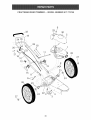
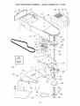
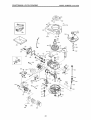
WEEDTRIMMER
For two years from date of purchase, when this Craftsman VVeedtrimmer
is maintained,
lubricated,
and tuned up according
to the operating and maintenance
instructions
in the
owner's manual, Sears will repair free of charge any defect in material or workmanship.
If this Craftsman Weedtrimmer
is used for commercial
applies for only 90 days from the date of purchase.
or rental
purposes,
this warranty
This Warranty does not cover:
Expendable
items which become worn during normal use, such as rotating lines,
belts, air cleaners and spark plug.
Repairs necessary
because of operator abuse or negligence,
including bent crankshafts and the failure to maintain the equipment
according to the instructions
contained in the owner's manual.
Warranty service is available by returning the Craftsman
Sears Service Center in the United States. This warranty
is in use in the United States.
This Warranty gives you specific
vary from state to state.
Sears,
Roebuck
legal rights,
Weedtrimmer
to the nearest
applies only while this product
and you may also have other
and Co., Dept. 817 WA, Hoffman
Estates,
rights which
IL 60179
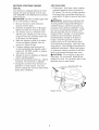
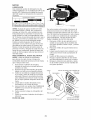
&WARNmNG:
This trimmer is equipped with an internal combustion
engine and should
not be used on or near any unimproved
forest-covered,
brush-covered
or grass-covered
land unless the engine's exhaust system is equipped with a spark arrester meeting applicable local or state laws (if any). If a spark arrester is used, it should be maintained
in
effective working order by the operator.
In the state of California the above is required by law (Section 4442 of the California
Public Resources
Code). Other states may have similar laws. Federal laws apply on
federal lands. A spark arrester for the muffler is available through your nearest Sears
service center (See the REPAIR PARTS section of this manual).
SAFETYGLASSES
L GENERAL
The operation of any trimmer can result in foreign objects thrown into
the eyes, which can result in severe eye damage.
Always wear safety
glasses or eye shields while operating your trimmer or performing
any
adjustments
or repairs. We recommend
a wide vision safety mask over
spectacles
or standard safety glasses.
OPERATmON
* Read, understand,
and follow all instructions on the machine and in the manual
before starting. Be thoroughly
familiar
with the controls and the proper use of
the machine before starting.
Do not put hands or feet near or under
rotating parts.
Keep all parts of your body away from
muffler and spinning line. A hot muffler
can cause serious burns.
,
Only allow responsible
individuals,
who
are familiar with the instructions,
to operate the machine.
,
Stay away from breakable objects, such
as house windows, auto glass, greenhouses, etc.
Clear the area of objects such as rocks,
toys, wire, bones, sticks, etc., which
could be picked up and thrown by the
spinning lines.
Be sure the area is clear of other people
before trimming,
particularly
small children and pets. Stop machine if anyone
enters the area.
,
,
,
,
,
,
Wear appropriate
clothing such as a
long-sleeved
shirt or jacket. Also wear
long trousers or slacks. Do not wear
shorts.
Do not wear loose clothing which could
get caught in this equipment.
Do not operate the machine when barefoot or wearing open sandals. Always
wear work gloves and sturdy footwear.
Leather work shoes or short boots work
well for most people. These will protect
the operator's ankles and shins from
small sticks, splinters, and other debris,
and improve traction.
Do not pull machine backwards
unless
absolutely
necessary.
Always look down
and behind before and while moving
backwards.
Do not operate the machine without
proper guards, plates or other safety
protective devices in place.
See manufacturer's
instructions
for
proper operation and installation
of
accessories.
Only use accessories
approved by the manufacturer.
Never use blades, wire, or flailing devices. This unit is designed for line trimmer use only. Use of other accessories
or attachments
will increase the risk of
injury.
Stop the rotating trimmer head when
crossing gravel drives, walks, or roads.
Wait for the cutting lines to stop rotating.
Stop the engine (motor) whenever you
leave the equipment
and allow it to cool,
before cleaning,
repairing or inspecting
the unit. Be sure the trimmer head and
all moving parts have stopped.
Operate only in daylight or good artificial
light.
Do not operate the machine while under
the influence of alcohol or drugs.
Never operate machine in wet grass.
Always be sure of your footing: keep a
firm hold on the handle and walk; never
run.
,, If the equipment
should start to vibrate
abnormally,
stop the engine (motor) and
check immediately
for the cause. Vibration is generally a warning of trouble.
,, Always wear safety goggles or safety
glasses with side shields when operating
machine.
H. SLOPE OPERATmON
Slopes are a majorfactor related to slip
and fall accidentswhich can result in
severe injury. All slopes requireextra caution. If you feel uneasy on a slope,do not
trim it.
DO:
* Trim across the face of slopes: never up
and down. Exercise extreme caution
when changing direction on slopes.
Remove obstacles such as rocks, tree
limbs, etc.
Watch for holes, ruts, or bumps. Tall
grass can hide obstacles.
DO NOT:
* Do not trim near drop-offs, ditches or
embankments.
The operator could lose
footing or balance.
Do not trim excessively
steep slopes.
Do not trim on wet grass. Reduced footing could cause slipping.
Never run a machine
area.
inside
a closed
Never make adjustments
or repairs with
the engine (motor) running. Disconnect
the spark plug wire, and keep the wire
away from the plug to prevent accidental
starting.
Keep nuts and bolts, especially trimmer
head and engine bolts, tight and keep
equipment
in good condition.
Never tamper with safety devices.
Check their proper operation regularly.
Keep machine free of grass, leaves, or
other debris buildup. Clean oil or fuel
spillage.
Allow machine to cool before
cleaning or storing.
Stop and inspect the equipment
if you
strike an object. Repair, if necessary,
before restarting.
Do not change the engine governor setting or overspeed
the engine.
Clean and replace safety and instruction
decals as necessary.
HL CHmLDREN
Tragic accidents
can occur if the operator
is not alert to the presence
of children.
Children are often attracted to the machine
and the trimming
activity.
Never assume
that children will remain where you last saw
them.
Keep children out of the trimming area
and under the watchful care of another
responsible
adult.
Be alert and turn machine
enter the area.
off if children
Before and while moving backwards,
look behind and down for small children.
Never allow children
chine.
to operate
the ma-
Use extra care when approaching
blind
corners, shrubs, trees, or other objects
that may obscure vision.
A_,Look for this symbol to point out
important safety precautions.
It means
CAUTION!!!
BECOME ALERT!!!
YOUR
SAFETY IS INVOLVED.
AWARNING:
In order to prevent accidental starting when setting up, transporting, adjusting or making repairs,
always disconnect
spark plug wire and
place wire where it cannot contact spark
plug.
AWARNmNG:
Engine exhaust, some
of its constituents,
and certain vehicle
components
contain or emit chemicals
known to the State of California to
cause cancer and birth defects or other
reproductive
harm.
mY. SERVICE
Use extra care in handling gasoline and
other fuels. They are flammable
and
vapors are explosive.
Use only an approved container.
Never remove gas cap or add fuel
with the engine running. Allow engine to cool before refueling. Do not
smoke.
Never refuel the machine indoors.
Never store the machine or fuel container inside where there is an open
flame, such as a water heater.
Move away from fueling
starting engine.
site before
_I, CAUTmON: Muffler and other engine
parts become extremely hot during
operation and remain hot after engine has
stopped. To avoid severe burns on contact,
stay away from these areas.
Read these instructionsand this manual in
its entirety beforeyou attemptto assemble
or operateyour newtrimmer.
iMPORTANT: This trimmer is shipped
WITHOUTOIL OR GASOLINEin the
engine.
Yournew trimmer has been assembled
at the factorywith the exceptionof those
parts left unassembledfor shipping
purposes. All parts such as nuts,washers, bolts, etc., necessaryto complete the
assemblyhavebeen placed in the parts
bag. Toensure safe and proper operation
of your trimmer,all parts and hardwareyou
assemblemustbe tightenedsecurely. Use
the correct tools as necessaryto ensure
proper tightness.
When right hand (RH) or left hand (LH) is
mentionedin this manual, it meanswhen
you are in the operatingposition(standing
behindthe handle).
TO REMOVE
TRmMMER
FROM
CARTON
1.
2.
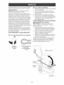
Remove loose parts included with trimmer.
Cut down two end corners of carton
3.
4.
and lay end panel down flat.
Remove all packing materials.
Roll trimmer out of carton and check
carton
parts.
HOW
thoroughly
TO SET
TO UNFOLD
for additional
UP YOUR
loose
TRmMMER
HANDLE
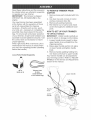
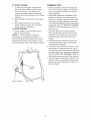
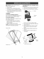
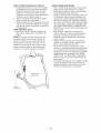
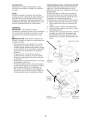
mMPORTANT:
Unfold handle carefully so
as not to pinch or damage control cables.
1.
2.
Loosen handle knob enough to allow
upper handle to be unfolded from the
shipping position.
Raise upper handle section into place
on lower handle and tighten handle
knob.
3.
LoosePartsPackedSeparately
20 oz.
Bottle of oH
Remove handle padding holding trimmer head control bar to upper handle.
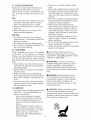
Your trimmer handle can be adjusted for
your trimming comfort.
Refer to "ADJUST
HANDLE" in the Service and Adjustments
section of this manual.
Trimmer Lines
(2) Sets
(0.!55 diameter
x 18.75 inches long)
Upper handb
Lift up
HandUe
knob
Lower
handle
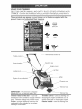
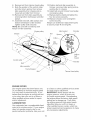
KNOW YOUR TRmMMER
READ THIS OWNER'S
MANUAL
AND
SAFETY
RULES
BEFORE
OPERATING
YOUR
TRIMMER.
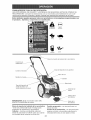
Compare the illustrations
with your trimmer to familiarize yourself with the
location of various controls and adjustments.
Save this manual for future reference.
These symbols
product.
Learn
may appear on your trimmer
or in literature
and understand
their meaning.
CAUTION
supplied
ENGINE
FAST
SLOW
FUEL
OIL
with
the
OFF
Trimmer head control bar
ThrottUe controU
Gasoline cap
Starter handUe
Engine cover
HandUe knob
Primer
Muffler
Engine oHcap w/dipstick
cover
Trimmer head
mMPORTANT:
This trimmer is shipped
WITHOUT
OIL OR GASOLINE
in the
Trimmer
head control
bar
- must
be
held down to the handle to engage trimmer
head. Release to stop the trimmer head.
Primer - pumps additional fuel from the
carburetor
to the cylinder for use when
starting a cold engine.
Trimmer Hne
Throttle
control
- used for starting and
stopping the engine and allows you to
select either fast or slow engine speed.
Starter
handle - used for starting the
TRIMMER
SAFETYGLASSES
The operation of any trimmer can result
in foreign objects being thrown into the
eyes, which can result in severe eye damage. Always wear safety glasses or eye
shields while operating your trimmer or
performing
any adjustments
or repairs. We
recommend
a wide vision safety mask over
spectacles
or standard safety glasses.
HOW
TO USE
YOUR
TRIMMER
ENGmNE SPEED
The engine speed is controNed by a
throttle located on the side of the upper
handle. Fast position is for starting and
normal trimming.
Slow is for light trimming
and fuel economy.
Stop is for stopping the
engine.
HEAD DRmVE CONTROL
Your trimmer is equipped with a trimmer
head drive control bar which will require
the operator to be positioned behind the
trimmer handle to operate the trimmer.
,_ Trimmer head rotation is controlled by
holding the trimmer head control bar
down to the handle.
Trimmer head rotation will stop when
the control bar is released.
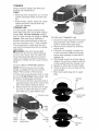
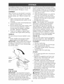
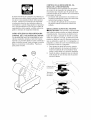
TO ADJUST
TRmMMmNG HEmGHT
_I_CAUTmON: Stop the engine and wait for
all moving parts to stop. Disconnect
spark
plug wire from spark plug and place wire
where it cannot come in contact with plug.
The height of cut can be set to six (6) different positions ranging from 1-1/2 inches
to 3 inches. Recommended
cutting height
for the average yard is 2 inches.
1. To adjust trimming height, push in the
locking plate tab and move trimmer
head up or down to desired position.
2. Release tab and be sure head is
locked into one of the six (6) height
positions.
Adj
Trimmer
Head
Locking
Plate Tab
\
!
\
BEFORE
STARTmNG
ADD
ENGINE
ADD OraL
Your trimmer is shipped without oil in the
engine. For type and grade of oil to use,
see "ENGINE" in the Maintenance
section
of this manual.
A CAUTION:
DO NOT overfill engine
oil, or it will smoke on startup.
1. Be sure trimmer is level and area
around oil fill is clean.
with
2.
Remove oil dipstick from oil fill spout.
Make sure that rim of spout is clean.
3. You receive a 20 oz. container of oil
with the unit. Slowly pour 3/4 (15 oz.)
of the oil from the container down the
4.
oil fill spout into the engine.
Wait one minute to allow oil to settle.
Insert and tighten dipstick,
move it to check oil level.
then re-
5.
Continue adding small amounts of
oil and rechecking the dipstick until it
reads full. DO NOT overfill, or engine
will smoke on startup.
6. Always be sure to retighten oil dipstick
before starting engine.
Check oil level before each use. Add oil
if needed.
Fill to full line on dipstick.
Change the oil after every 25 hours of
operation or each season. You may
need to change the oil more often under
dusty, dirty conditions.
GASOUNE
Fill fuel tank. Use fresh, clean, regular
unleaded gasoline with a minimum of
87 octane.
Do not mix oil with gasoline.
Purchase fuel in quantities that can be
used within 30 days to assure fuel freshness.
_,WARNmNG:
Experience
indicates that
alcohol blended fuels (called gasohol or
using ethanol or methanol) can attract
moisture which leads to separation
and
formation of acids during storage.
Acidic
gas can damage the fuel system of an
engine while in storage.
To avoid engine
problems, the fuel system should be
emptied before storage of 30 days or
longer. Drain the gas tank, start the
engine and let it run until the fuel lines
and carburetor
are empty. Use fresh fuel
next season.
See Storage Instructions
for
additional
information.
Never use engine
or carburetor
cleaner products in the fuel
tank or permanent
damage may occur.
A CAUTmON: Fill to bottom of gas tank
filler neck. Do not overfill. Wipe off any
spilled oil or fuel. Do not store, spill or use
gasoline near an open flame.
Gasoline fiibr cap
Engine oil cap
TO START
TR(MM(NG T(PS
ENGmNE
1.
To start a cold engine, push primer
three (3) times before trying to start.
Use a firm push. This step is not
usually necessary
when starting an
engine which has already run for a few
minutes.
2.
Move throttle
tion.
control
lever to fast posi-
3.
Hold upper handle firmly and pull
starter handle quickly. Do not allow
starter rope to snap back.
TO STOP ENGmNE
To stop engine, move throttle control
lever to stop position.
NOTE: In cooler weather it may be
necessary
to repeat priming steps. In
warmer weather overpriming
may cause
flooding and engine will not start. If you
do flood engine, wait a few minutes before
* Set the throttle control in the fast position. If the weeds or grass are tall and
thick, operate the trimmer at a slower
walking speed.
Frequently clean the underside of the
trimmer to remove any grass build up.
Keep top of engine around starter clear
and clean of grass clippings and chaff.
This will help engine air flow and extend
engine life. See "TO REMOVE ENGINE
COVER" in the Maintenance
section of
this manual.
For best results and longer lasting
line, use the ends of the line to do the
cutting. This is easily done by moving
slowly through very thick and heavy
weeds.
Use the left side of trimmer when trimming along fences, walls, fiowerbeds
and other such objects.
If trimmer lines become too short, it will
take longer to complete the job. If trimmer lines are worn to less than half their
original length, they should be replaced.
See "TO REPLACE TRIMMER
LINE" in
the Maintenance
section of this manual.
Trimmer head contact with concrete, asphalt or other hard surfaces may cause
premature
wear of the ball on bottom of
trimmer head.
Starter handle
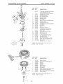
MAINTENANCE
SCHEDULE
REGULAR
SERV,OE
Check for Loose Fasteners
R
Clean Trimmer
°,_o_J
/_./_,_'_
AS YOU COMPLETE
T
./___
_/'_0_
SERVICE
"
I1_
DATES
I1_
_
I_
I
M
Clean Under Engine Cover
Check
R
Change
G
v'
Drive Belt / Pulleys
Check / Replace Trimmer
Check
11_2
Lines
Engine Oil Level
Engine
t#'3
tl_
Oil
I,,#1,2
Clean Air Filter
Inspect Muffler
Clean or Replace
Replace
I1_ 2
!_
Spark Plug
!_
_2
Air Filter Paper Cartridge
1 - Change more often when operating under a heavy load or in high ambient temperatures,
2 - Service more often when operating in dirty or dusty conditions.
3 - Replace trimmer lines when they have worn to half their original length.
GENERAL
RECOMMENDATmONS
wheel bearings. Viscous lubricants will
attract dust and dirt that will shorten the
The warranty on this trimmer does not
cover items that have been subjected to
operator abuse or negligence.
To receive
full value from the warranty, operator must
maintain trimmer as instructed
in this
manual.
life of the self- lubricating
bearings. If you
feel they must be lubricated,
use only
a dry, powdered graphite type lubricant
sparingly.
Some adjustments
will need to be made
periodically
to properly maintain your unit.
All adjustments
in the Service and Adjustments section of this manual should be
checked at least once each season.
PRODUCT
Serial No.
Date of Purchase:
Once a year, replace the spark plug and
replace air filter element.
A new spark
plug and clean/new air filter element
assure proper air-fuel mixture and help
your engine run better and last longer.
Follow the maintenance
schedule in this
manual.
BEFORE
EACH USE
1.
2.
Check
Check
engine oil level.
for loose fasteners.
3. Clean under engine
LUBRmCATmON
SPECIFmCATmONS
cover.
Gasoline Type:
Gasoline Capacity:
UnUeaded Regular
1.25 Quarts
Oil Type:
(APFSF°SJ)
Oil Capacity:
SAE 30 (Above 32 -°F)
SAE 5W-30 (Below 32 -°F)
20 ounces
Spark Plug:
Champion RJ19LM4
(Gap: .045")
Trimmer
Line Diameter:.155
inch
Trimmer
Line Length:
18.75 inches
To prolong the useful life of your trimmer,
change engine oil as recommended
in this
section of Owner's Manual.
The model and serial numbers will be
found on a decal attached to the rear of
the trimmer. Record both serial number
mMPORTANT:
and date of purchase
above.
Do not oil or grease
plastic
10
in space
provided
Alwaysobserve safety ruleswhen performing any maintenance.
TmRES
• Keep tires free of gasoline, oil, or insect
control chemicals
which can harm rubber.
• Avoid stumps, stones, deep ruts, sharp
objects and other hazards that may
cause tire damage.
TRmMMER UNE
For best results, rep{ace trimmer lines
when they have worn to half their originat
length. Use o155 inch diameter
trimmer
line. Cut new trimmer line length to 18-3/4
inches.
After new line is installed on
TO REPLACE
1.
trimmer head, check all lines so they do
not vary more then one (1) inch in length.
This is important to make sure the trimmer head is balanced and will not vibrate
2.
abnormally.
_i, WARNmNG: Use only the specified
trimmer line. Do not use other materials
3.
such as wire, string, rope, etc. Wire can
break off during trimming and become a
dangerous
missile that can cause serious
injury.
4.
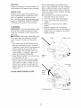
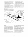
TO CUT LINE TO PROPER
LENGTH
5.
6.
NOTE: Trimmer line pre-cut to proper
length is available for this unit; see the
Repair Parts section of this manual.
7.
If trimmer line is purchased
in bulk, it must
be cut to 18-3/4 inches before using. Use
the builtqn length guage as follows:
1. From front of trimmer, place the end of
spooled trimmer line at the mark on the
side of the debris shield as shown.
2.
TRIMMER
LINE
Disconnect
spark plug wire
plug and place wire where
come in contact with spark
Remove worn trimmer line
from spark
it cannot
plug.
from line
carrier plate.
Fold new, cut to length, trimmer line
in half and insert folded end through
carrier plate opening to back side of
retainer clip.
With folded end of line at back side of
retainer clip, pull line outward until line
is fully seated under the retainer clip.
Repeat on other side of carrier plate.
Check all lines to be sure they are the
same length.
Reconnect
spark plug wire to spark
plug.
Trimmer
line
Wrap trimmer line around front of chassis cover to other side and cut at the
"22" mark
(your unit's width of cut).
Chassis cover
Carrier plate
opening
Wrap
line
around
Debris
shield
mark
End of
spooled line
New
trimmer
line
Retainer
clip
11
LUBRmCATmON
Use only high quality detergent oil rated
with API service classification
SF-SJ. Select the oil's SAE viscosity grade according to your expected operating temperature.
SAE VISCOSITY
F
-20
c -_o
0
30
-2_
TEMPERATURE
-1_
32
GRADES
40
_
RANGE ANTICIPATED
60
1'o
BEFORE
80
_o
100
_o
4_
Container
NEXT OIL CHANGE
oi_viscchar
tIe
AmR FmLTER
NOTE: Although multi-viscosity
oils
(5W30, 10W30 etc.) improve starting in
cold weather, these multi-viscosity
oils will
result in increased oil consumption
when
used above 32°R Check your engine oil
level more frequently to avoid possible
engine damage from running low on oil.
Your engine will not run
be damaged by using a
place the air filter every
eration or every season,
first. Service air cleaner
dusty conditions.
properly and may
dirty air filter. Re100 hours of opwhichever occurs
more often under
Do not wash air filter.
Change the oil after every 25 hours of
operation or at least once a year if the unit
is not used for 25 hours in one year.
Check the crankcase
oil level before
TO CHANGE
starting the engine and after each five (5)
hours of continuous
use. Tighten oil plug
securely each time you check the oil level.
2.
3.
Remove the air filter by turning clockwise to the stop and pull away from
collar.
Remove filter from inside of cover.
Clean the inside of the cover and the
4.
5.
collar to remove any dirt accumulation.
Insert new filter into cover.
Put air filter cover and filter into collar
6.
aligning the tab with the slot.
Push in on cover and turn counter-
TO CHANGE
ENGINE
1.
OIL
NOTE: Before tipping trimmer to drain oil,
drain fuel tank by running engine until fuel
tank is empty.
1.
2.
3.
4.
5.
6.
7.
clockwise
Disconnect
spark plug wire from spark
plug and place wire where it cannot
come in contact with spark plug.
Remove engine oil cap; lay aside on a
clean surface.
Tip trimmer on its side as shown
drain oil into a suitable container.
AIR FILTER
to tighten.
Collar
Turn
Clip
and
Rock
trimmer back and forth to remove any
oil trapped inside of engine.
Wipe off any spilled oil from trimmer
and side of engine.
Fill engine with oil (See "ADD OIL_' in
the Operation section of this manual).
Replace engine oil cap.
Reconnect
spark plug wire to spark
plug.
clockwise
to
remove
Slot
Air filter
Tab
Air filter cover
12
Turn
counter°
clockwise to tighten
MUFFLER
Clean under engine cover before each
use, or more frequently
in heavy cutting or
dirty conditions.
Engine cover screen and
engine air intake screen must be kept free
of dirt and chaff to prevent engine damage
from overheating.
Be sure engine is cool before cleaning.
1. Unscrew knob on top of cover.
2. Lift cover up and away from engine.
3. Clean cover and cover screen thor-
Inspect and replace corroded muffler as it
could create a fire hazard and/or damage.
SPARK
PLUG
Replace spark plugs at the beginning
of
each mowing season or after every 100
hours of operation,
whichever occurs
first. Spark plug type and gap setting are
shown in "PRODUCT
SPECIFICATIONS"
in Maintenance
section of this manual.
4.
5.
mMPORTANT:
For best performance,
keep
trimmer free of built-up grass and trash.
Clean the underside of your trimmer after
each use.
oughly.
Clean top of engine
screen.
Replace engine cover and tighten
knob securely. Be sure the front tabs of
engine cover are located in the slots in
engine housing.
_ICAUTmON:
Disconnect
spark plug wire
from spark plug and place wire where it
cannot come in contact with the spark
plug.
• Turn trimmer on its side. Make sure air
Knob
\
filter and carburetor
are up. Clean the
underside of your trimmer by scraping to
remove build-up of grass and trash.
• Clean engine often to keep trash from
accumulating.
A clogged engine runs
hotter and shortens engine life.
• Keep finished surfaces and wheels free
of all gasoline, oil, etc.
• We do not recommend
using a garden
hose to clean trimmer unless the elec-
and air intake
/
Engine cover
Starter
rope
trical system, muffler, air filter and carburetor are covered to keep water out.
Water in engine can result in shortened
engine life.
Threaded
stud
Engine
cover
screen
CLEAN UNDER ENGmNE COVER
Air intake screen
13
Housing slots
CAUTmON:
Before performing
service and adjustments:
1.
2.
3.
TO REI\,_OVE/REPLACE TRmI_,_MERHEAD
any
DRmVE BELT
1. Remove
Stop engine.
Make sure the rotating lines and all
moving parts have completely
stopped.
Disconnect
spark plug wire from spark
plug and place where it cannot come in
contact with plug.
TO ADJUST
at front of chassis
cover.
Lift cover up and away from trimmer.
Remove the two (2) screws on sides of
TRmI_IMmNG HEmGHT
See "TO ADJUST
the Operation
TO ADJUST
2.
3.
screw
TRIMMING
HEIGHT"
Chassis
in
section of this manual.
HANDLE
The upper handle may be adjusted to different height positions.
,, Loosen handle knob only enough to
allow the upper handle to pivot to the
desired position.
,, Tighten handle knob securely.
NOTE: The handle knob and bolt may be
reversed for left handed operation.
4.
5.
Upper handb
6.
7.
trimmer securing the debris shield.
Turn trimmer on its side with carburetor
and fuel cap up.
Remove the two (2) screws on underside of trimmer securing the debris
shield.
Slide the debris shield rearward and
remove.
Remove belt from engine
crankshaft.
pulley on
I!
,/
gine
pulley
--....
/'
Debris shield screws
Handle knob
14
8.
9.
Remove belt from trimmer head pulley.
Note the position of the control cable
and idler return spring, then remove
idler assembly from chassis and remove belt and idler from trimmer.
12.Poskion
belt and idler assembly in
trimmer, reconnect idler spring and assemble idler to chassis.
13. Install belt around trimmer head pulley
and engine pulley.
14. Replace debris shield and tighten the
four (4) screws securely.
15. Replace chassis cover and tighten
screw securely.
Always use Craftsman
replacement
parts
to assure proper fit and long life.
10. Remove belt from idler assembly
by
removing bottom belt keeper and idler
pulleys.
11 .Assemble
new belt, idler pulleys and
bottom belt keeper to idler bracket.
Tighten pulley bolts securely.
NOTE: Be sure belt is inside top belt
keeper on idler assembly.
Idler bracket
Engine pulley
Chassis
.- _" -.
Nut
Fiat idler
S
/
C
\
1
I
I
k
k
Bottom
belt
keeper
,,
Control cable
Fiat idler
BeUt
"2
Idler assembly
tl
Top belt keeper
"
"-- "_ I I
Trimmer head
ENGmNE
pulley
SPEED
Your engine speed has been factory set.
Do not attempt to increase engine speed
or it may result in personal injury. If you
believe that the engine is running too fast
or too slow, take your unit to a Sears or
other qualified service center for repair
and/or adjustment.
to a Sears or other qualified service center
for repair and/or adjustment.
mMPORTANT: Never tamper with the
engine governor, which is factory set
for proper engine speed. Overspeeding
the engine above the factory high speed
setting can be dangerous.
If you think
the engine-governed
high speed needs
adjusting, take your unit to a Sears or
other qualified service center, which has
proper equipment
and experience
to make
any necessary
adjustments.
CARBURETOR
Your carburetor
has a nonadjustable
fixed
main jet for mixture control.
If your engine
does not operate properly due to suspected carburetor
problems, take your unit
15
Immediately
prepare your trimmer for storage at the end of the season or if the unit
will not be used for 30 days or more.
or methanol) can attract moisture which
leads to separation
and formation of acids
during storage. Acidic gas can damage the
fuel system of an engine while in storage.
1. Drain the fuel tank.
When trimmer is to be stored for a period
of time, clean it thoroughly,
remove all dirt,
grease, leaves, etc. Store in a clean, dry
area.
1.
Clean entire trimmer (See "CLEANING" in the Maintenance
section of this
2.
manual).
Lubricate as shown in the Maintenance
section of this manual.
3.
Be sure that all nuts, bolts, screws,
4.
2.
NOTE: Fuel stabilizer is an acceptable
alternative
in minimizing
the formation
of fuel gum deposits during storage.
Add stabilizer to gasoline in fuel tank or
storage container.
Always follow the mix
ratio found on stabilizer container.
Run
and
pins are securely fastened.
Inspect
moving parts for damage, breakage
and wear. Replace if necessary.
Touch up all rusted or chipped paint
surfaces; sand lightly before painting.
You can fold your trimmer
engine at least 10 minutes after adding
stabilizer to allow the stabilizer to reach
the carburetor.
and carburetor
ENGmNE Oral
handle for stor-
age.
Loosen handle knob enough to allow
upper handle to be folded forward.
mMPORTANT:
When folding the handle for
storage or transportation,
be sure to fold
the handle as shown or you may damage
the control cables.
Do not drain the gas tank
if using fuel stabilizer.
Drain oil (with engine warm) and replace
with clean engine oil. (See "ENGINE"
in
the Maintenance
section of this manual).
CYUNDER
1.
2.
3.
',', #
Start the engine and let it run until the
fuel lines and carburetor
are empty.
Never use engine or carburetor
cleaner
products in the fuel tank or permanent
damage may occur.
Use fresh fuel next season.
',',#
4.
Remove spark plug.
Pour one ounce (29 ml) of oil through
spark plug hole into cylinder.
Pull starter handle slowly a few times
to distribute oil.
Replace
with new spark
Do not store gasoline
to another.
plug.
from one season
Replace your gasoline can if your can
starts to rust. Rust and/or dirt in your
gasoline will cause problems.
If possible, store your unit indoors and
cover it to protect it from dust and dirt.
Cover your unit with a suitable protective
cover that does not retain moisture.
Do
Upper
Handle
knob
not use plastic. Plastic cannot breathe,
which allows condensation
to form and
will cause your unit to rust.
mMPORTANT:
Never cover trimmer
FUEL
SYSTEM
while
engine and exhaust areas are still warm.
_,CAUTmON:
Never store the trimmer
mMPORTANT:
It Is important to prevent
gum deposits from forming in essential fuel
system parts such as carburetor,
fuel filter,
fuel hose or tank during storage. Also,
experience
indicates that alcohol blended
fuels (called gasohol or using ethanol
with gasoline in the tank inside a building
where fumes may reach an open flame
or spark. Allow the engine to cool before
storing in any enclosure.
16
TROUBLESHOOTING
PROBLEM
Does not start
Clean/replace air filter.
CAUSE
CORRECTION
.
Dirty air filter.
2. Out of fuel.
3. Stale fuel.
4. Water
in fuel.
5. Spark plug wire is
disconnected.
6. Bad spark plug.
7. Throttle control lever not
in correct
position
1.
2. FIll fuel tank.
3. Drain tank and refill with
fresh, clean fuel.
4. Drain fuel tank and
carburetor
and refill tank
with fresh gasoline.
5. Connect wire to plug.
6. Replace spark plug.
7. Move throttle lever to FAST
position.
_ITequippea).
Loss of power
1. Dirty air filter.
2. Buildup of grass, leaves,
and trash under trimmer.
3. Too much oil in engine.
4. Walking speed too fast.
1. Clean/replace
air filter.
2. Clean underside of trimmer
and trimmer head.
3. Check oil level.
4. Trim at slower walking
Excessive
Vibration
1. Lines uneven or broken.
2. Loose nuts or bolts.
1. Check trimmer lines.
2. Check all hardware,
including engine bolts.
Starter
1. Bent engine
1. Contact
Loss
drive
rope
of head
crankshaft.
1. Belt not driving.
1. Handle height
right for you.
Poor trimming
performance
1. Trimmer line length is
too short.
in correct
V.l_,,i..l_vv,
Trimmer head
does not
retain mine
position
control
not
lever not
position
1. Adjust handle height
to suit.
1. If line is worn or broken
to
half original length,
replace line.
2. Move throttle lever to FAST
position.
i.
1. Trimmer line not
properly installed.
2. Broken line retainer
3. Incorrect
or other
1. Put belt on pulleys or
replace belt _t broken.
Hard to push
2. Throttle
a Sears
size of
17
clip.
1. Follow instructions
in the
Maintenance
section.
2. Replace string carrier plate
assembly.
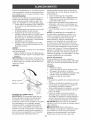
3. Use .155 diameter
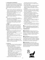
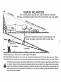
Opsrats a trimmer
across the face
of slopes, nsver up or down slop_°
Co
10 DEGREES
15 DEGREES
Especificaciones
deUProducto .......................
27
GARANTiA LIMITADA DE DOS AltOS PARA LA RECORTADORA PARA MALA HIERBA PARA
MALA HIERBA CRAFTSMAN
Pot dos (2) a_os, a partir de la fecha de compra, cuando esta recortadora para mala hierba Craftsman se mantenga, lubrique y aline segun las instrucciones para la operaci6n y el mantenimiento
en el manual del due_o, Sears reparara gratis todo defecto en el material y la mano de obra.
Si la recortadora para mala hierba Craftsman se usa para fines comerciales o de arriendo, esta
garantia s61o se aplica pot noventa (90) dias a partir de la fecha de compra.
Esta Garantia no cubre:
Articulos que se desgastan durante el uso normal tabs como las lineas rotatorias las correas,
los filtros de aire y las bujias.
Reparaciones necesarias debido al abuso o a la negligencia del operador, incluy6ndose a los
cigOe_ales doblados y a la falta de mantenimiento del equipo segun las instrucciones que se
incluyen en el manual del due_o.
El servicio de garantia esta disponible al devolver la recortadora para mala hierba Craftsman al
Centro de Servicio Sears mas cercano en los Estados Unidos. Esta garantia se aplica solamente
mientras el producto este en uso en los Estados Unidos.
Esta Garantia le otorga derechos legales especificos,
que varian de estado a estado.
Sears,
Roebuck
and Co., Dept. 817 WA, Hoffman
y puede que tambi6n tenga otros derechos
Estates,
Illinois
60179
ADVERTENCIA:
Este recortadora viene equipado con un motor de combusti6n interna y no
se debe usar sobre, o cerca, de un terreno no desarrollado cubierto de bosques, de arbustos o
de cesped, o menos que el sistema de escape del motor venga equipado con un amortiguador de
chispas que cumpla con las byes locales o estatales (si existen). Si se usa un amortiguador de
chispas, el operador debe mantenerlo en condiciones de trabajo eficientes.
En el estado de California, la ley exige Io anterior (Secci6n 4442 del "California Public Resources
Code"). Otros estados pueden contar con otras byes parecidas. Las byes federales se aplican en
la tierras federales. Su Centro de Servicio Sears mas cercano tiene disponible amortiguadores de
chispas para el silenciadoL (Vea la secci6n de Partes de Repuesto en el manual Ingl6s del dueSo.)
19
&
&
SEGURIDAD
La operaci6n de cualquier recortadora puede hacer que salten objetos
extra_os dentro de sus ojos, Io que puede producir da_os graves en estos.
Siempre use anteojos de seguridad o protecci6n para los ojos mientras opere
su recortadora o cuando haga ajustes o reparaciones. Recomendamos una
mascara de seguridad de visi6n amplia, para uso espejuelos o anteojos de
seguridad estandarte.
1. OPERACION GENERAL
o Antes de empezar, debe familiarizarse
completamente con los controles y el uso
correcto de la maquin& Para esto, debe leer
y comprender todas las instruceiones que
aparecen en la maquina yen los manuales
de operaci6n.
No ponga las manos o los pies cerca o debajo de las partes rotatoria&
Mantener todas las partes del cuerpo lejos
del silenciador del escape y la I[nea de
rotaci6n. El silenciador caliente puede causar
serias quemaduras.
Permita que solamente las personas responsables que est6n familiarizadas con las
instrucciones operen la maquina.
Mantenerse lejos de objetos que pueden
romperse, como cristales de casa, cristales
del choche, invernaderos, etc.
Despeje el area de objetos tabs como piedras, juguetes, alambres, huesos, palos, etc.
que pueden set recogidos y lanzados pot las
I[neas giradora&
Asegurese que el area no se hallen personas, y particularmente niSos pequeSos y
cachorros antes de recortar. Pare la maquina
si alguien entra en el area.
Use ropa apropaida, tal como camisa de
manga larga o chaqueta y pantalones largos.
No use pantalones cortos shorts.
No use ropa suelta, ya que esta podr[a atorarse en el equipo.
No opere la maquina sin zapatos o con
sandalias abiertas. Use siempre guantes
de trabajo y calzado fuerte. Los zapatos de
trabajo de piel o botas cortas son apropiados
para la mayor[a de las persona& Estos no
s61o protegerian los tobillos y espinellas del
operador de pequeSas ramas, astillas y otros
desperdicios, sino que ademas mejoraran la
tracci6n.
o No tire de la maquina hacia atras a menos
que sea absolutamente necesario. Mire
siempre hacia abajo y hacia detras antes y
mientras que se mueve hacia atras.
No opere la maquina sin los respectivos
resguardos, placas u otros aditamentos
dise_ados para su protecci6n y seguridad.
o Refi@ase alas instrucciones del fabricante
para el funcionamiento e instalaci6n de
accesorio& Use unicamente accesorios aprobados pot el fabricante.
o Nuca utilice cuchillas, cables o dispositivos
tipo mayak Esta unidad esta proyectada para
fucionar solamente con una I[nea de recortadora. La utilizaci6n de cualquier otto material,
acessorio o dispositivo secundario aumenta
el riesgo de lesi6nes y da_os a la propiedad.
Detenga la cabeza giratoria de la recortadora
cuando cruce pot calzadas, calles o caminos
de grava. Espere que las cuerdas de corte
paten de giran
Pare el motor siempre que tenga que dejar el
equipo, antes de limpiar, reparar o inspeccionar la unidad. Asegurese de que la cabeza
de la recortadora y todas las partes en movo
imiento se hayan detenido.
Opere solamente con luz del d[a o con una
buena luz artificiak
No opere la maquina bajo la influencia del
alcohol o de las drogas.
Nunca opere la maquina cuando la hierba
est6 mojad& Asegurese siempre de tenet
buena tracci6n en sus pies; mantenga el
mango firmemente y camine; nunca corr&
Si el equipo empezara a vibrar de una
manera anormal, pare el motor y revise de
inmediato para averiguar la caus& Genero
almente la vibraci6n suele indicar que existe
alguna aver[&
Siempre use galas de seguridad o anteojos
con protecci6n lateral cuando opere la maquina.
20
li. OPERACI6N EN PENDIENTE
Los accidentes ocurren con mas frecuencia en
Uascuestas. Estos accidentes ocurren debido a
resbaUadas o caidas, UascuaUes pueden resuUtar
en graves Uesiones. Operar Uarecortadora en
cuestas requiere mayor concentraci6n. Si se
siente inseguro en una cuesta, no Uarecorte.
Sh
o Puede recortar a trav6s de Uasuperficie de Ua
cuesta, nunca hada arriba y hacia abajo. Pro°
ceda con extrema precauci6n cuando cambie
de direcci6n en Uascuestas.
o Renueva todos Uosobjetos extrafios, taUes
como guijarros, ramas, etc.
o Debe prestar atend6n a hoyos, baches o
protuberandas. Recuerde que Uahierba aUta
puede esconder obstAcuUos.
NO:
o No recorte cerca de pendientes, zanjas o
terrapUenes. EUoperador puede perder Uatraco
ci6n en Uospies o eUequHibrio.
o No recorte cuestas demasiado indinadas.
o No recorte en hierba mojada. La reducci6n
en la tracci6n de la pisada puede causar
resbalones.
III. NIl, lOS
Se pueden producir accidentes tragicos si el
operador no presta atenci6n a la presencia
de los nifios. A menudo, los nifios se sienten
atraidos por la maquina y por la actividad de
la siega. Nunca suponga que los nifios van a
permanecer en el mismo lugar donde los vio por
Oltima vez.
o Mantenga a los nifios alejados del Area de
la siega y bajo el cuidado estricto de otra
persona adulta responsable.
o Est6 alerta y apague la maquina si hay nifios
que entran al Area.
o Antes y durante el retroceso, mire hacia
atras y hacia abajo para verificar si hay nifios
pequefios.
o Nunca permita que los ni_os operen la mao
qu[na.
o Tenga un cuidado extra cuando se acerque
a esquinas donde no hay visibi]idad, a los
arbustos, arbo]es u otros objetos que pueden
intefferir con su ]inea de visi6n.
carburante antes de poner en march&
o Nunca haga funcionar una maquina dentro
de un Area cerrada.
o Nunca haga ajustes o reparaciones mientras
el motor est6 en marcha. Desconecte el
cable de la bujia, y mant6ngalo a cierta
distancia de 6sta para prevenir un arranque
accidental.
o Mantenga las tuercas y los pernos, especiaF
mente los pernos del motor y de la cabeza
de recortes, apretados y mantenga el equipo
en buenas condiciones.
o Nunca manipule de forma indebida los
dispositivos de seguridad. Controle regular°
mente su funcionamiento correcto.
o Mantenga la maquina libre de hierba, hojas u
otras acumulaciones de desperdicio. Limpie
los derrames de aceite o combustible. Per°
mita que la maquina se refresque antes de
limpiarla o almacenarla.
Pare e ]nspeccione el equipo s] le pega a un
objeto. RepArelo, si es necesario, antes de
hacer[o arrancar.
o No cambie el ajuste del regulador del motor
ni exceda su velocidad.
o Limpiar y sustituir las calcomanias relativas a
instrucciones y seguridad cuando necesario.
_ilLBusque este simbolo que sefiala las precauo
ciones de seguridad de importancia. Ouiere
decir - i i iATENCION!!!iiiESTE
ALERTO!!! SU
SEGURIDAD ESTA
COMPROMETIDA.
,Ji_ADVERTENCIA: Siempre desconecte el
alambre de la bujia y p6ngalo donde no pueda
entrar en contacto con la bujia, para evitar el
arranque por accidente, durante la preparaci6n,
el transporte, el ajuste o cuando se hacen
reparaclones.
,_iI,ADVERTENCIA: El tubo de escape del motor, algunos de sus constituyentes y algunos
componentes del vehiculo contienen o despreno
den productos quimicos conocidos en el Estado
de California como causa de cancer y defectos
al nacimiento u otros dafios reproductivos.
dI_PRECAUCI6N: El silenciador y otras
piezas del motor Ilegan a sre extremadamente
calientes durante la operaci6n y siguen siendo
calientes despu6s de que el motor haya parado.
Para evitar quemaduras severas, permanezca
lejos de estas Areas.
iV. SERViCIO
Tenga cuidado extra al manejar la gasolina y
los demas combustibles. Son infiamables y
los gases son explosivos.
Use solamente un envase aprobado.
Nunca remueva la tapa del dep6sito de
gasolina o agregue combustible con el
motor funcionando. Permita que el motor
se enfrie antes de volver a poner combuso
tible. No fume.
Nunca vuelva a poner combustible en la
maquina en recintos cerrados.
Nunca almacene la maquina o el envase
del combustible dentro de algOn Dgar en
donde haya una llama expuesta, tal como
la del calentador de agua.
o Alejarse de la zona de abastecimiento del
21
Leaestasinstrucciones
y estemanuaicompbtamenteantesdetratardemontaru operarsu
nuevarecortadora.
IMPORTANTE:
Estarecortadora
vbne SUN
ACEFEO GASOUNAenelmotor.
Sunuevarecortadora
hasidomontadaenHa
f_,bdca
conHaexcepci6n
deaqueHas
partesque
se dejaronsinmontarporrazonesde envio.
TodasHaspartescomoHas
tuercas,HasarandeHas,bs pernos,etc.,necesarias
paracompbtar
ei montajehartsidocobcadasenHabobade
partes.Paraasegurarse
quesu recortadora
funcionedeformasegurayadecuada,todas
Haspartesy bs articubsdeferreteriaquese
montentbnenqueserapretadosfirmemente.
UseHasherrambntas
correctasadecuadaspara
asegurarunapretadofirme.
CuandoHamanoderechao Hamanoizquierda
esta'nmencionadas
enestemanualsignifica
queustedestasituadoenHaposici6nde opera°
dor,detrasdellmango.
PARA REMOVER LA RECORTADORA
Piezas sueltas empaquetadas
20 onzas.
BoteHa de
aceite
pot separado
DE LA CAJA DE CARTON
1.
2.
3.
4.
Remueva Haspartes sueitas que se
con Harecortador&
Corte Hasdos esquinas de los extremos
de Hacaja de cart6n y tienda el panel dell
extremo piano.
Remueva todo el material de embalaje.
Haga rodar Harecortadora hacia afuera de
Hacaja de cart6n y revisela cuidadosamente
para verificar si todavia quedan partes
sueitas adicionales.
COMO PREPARAR SU RECORTADORA
PARA DESDOBLAR EL MANGO
mMPORTANTE: Despiiegue el mango con
mucho cuidado para no apretar o dafiar los
cables de contro].
1.
Afiojar Haperilla de] mango 1o suficiente
para permitir el mango superior ser desdobiado con respecto a Haposici6n de envio.
2. Levante Hasecci6n de] mango superior
hasta su ]ugar en el mango inferior, y
apriete Hamanilla de] mango.
3. Remueva Hacu_a de] mango que sujeta Ha
barra de] control de] cabeza] de Harecortadora aMmango superior.
El mango de su recortadora puede ajustarse
segun Heacomode para recortar. Refi6rase
a "AJUSTE DEL MANGO" en HaSecci6n de
Servicio y Ajustes de este manua].
2 Juegos de cuerda de
recortadora
(0.!55 de di_metro
x 18.75)
Mango superior
/
Levantar
Manilla
de mango
Mango
inferior
22
FAMmUARiCESECON SU RECORTADORA
LEA ESTE MANUAL DE USUARIOY LAS REGLAS DE SEGURIDAD ANTES DE OPERAR SU
RECORTADORA. Compare las ilustraciones con su recortadora para familiarizarse con la ubicaci6n de los diversos controles y ajustes. Guarde este manual para referencia en el futuro.
Estos s_mbomos pueden aparecer sobre su recortadora
emproducto.
Aprenda y comprenda sus significados.
o en las p_ginas proporcionadas
ATTENCION O
ADVEFtTENCIA
RAPIDO
COMBUSTIBLE
con
MOTOR
APAGADO
LENTO
ACEITE
Barra de mando del cabezal de la recortadora
Control de la
aceleraci6n
del deposito de la gasolina
Cord6n arrancador
Filtro de aire
Manilla de mane
Cebador
Tapa del deposito
aceite del motor con
varilla indicadora
de nivel
Cubierta del
chasis
Cabeza de ia
recortadora
IMPORTANTE: Esta recortadora viene SiN
ACEITE O GASOLINA en motor.
Linea de ia
recortadora
Barra de mando del cabizal de la recortadora
- debe ser presionada hacia el mango para
enganchar el cabezal de la recortadora.
Cebador - bombea combustible adicional
desde el carburador al cilindro para uso cuando
se necesita hacer arrancar un motor frio.
Cord6n arrancador - se usa para hacer arrancar el motor.
Control de la aceleraci6n - se usa para hacer
arrancar el motor y le permite seleccionar la
velocidad del motor ya sea ra'pida o lenta.
23
SEGURIDAD
El funcionamiento de cualquier recortadora pu=
ede hacer que salten objetos extra_os dentro de
sus ojos, Io que puede producir da_os graves
a 6stos. Siempre use anteojos de seguridad
o protecci6n para los ojos mientras opere su
recortadora o cuando haga ajustes o reparacio=
nes. Recomenclamos el uso de una careta de
seguridad de visi6n amplia, a utilizar sobre las
gafas o anteojos de seguriclad est&ndar.
C6MO
UTmLmZAFISU F1ECOFITADOFIA
CONTROL DE LA VELOCIDAD DEL MOTOR
La vebcidad deUmotor es controUada por una
v&lvula reguladora situada al lado del mango
superior. La posici6n rapida es para comenzar y
para el recorte normal. Lento es para el recorte
ligero y economizar combustible. Paracla es
para parar el motor.
CONTROL DE LA IMPULSION DEL CABEZAL DE LA FIECOFITADOFIA
Su recortadora viene equipada con una barra
de control de la impulsi6n del cabezal de la
recortadora que requiera que el operador este
colocado detras de la palanca de la recortadora
para operar la misma.
o La rotaci6n del cabezal de la recortadora se
controla manteniendo la barra de control del
cabezal hacia abajo al mango.
* La rotaci6n del cabezal de la recortadora
se parara cuando la barra de control sea
soltada_
PAFIA AJUSTAFI ALTUFtA DEL FIECOFITE
_IPFIECAUCION:
Pare el motor y espere hasta
que todas la piezas m6viles se hayan detenido
completamente. Desconecte el alambre de la
bujia de la bujia y p6ngalo en doncle no pueda
entrar en contacto con 6sta. La altura del corte
puede set fijada en seis (6) diversas posiciones
que se extienden a partir de 1-1/2 pulgadas a 3
pulgadas. La altura de corte recomendacla para
un cercaclo normal es 2 pulgadas.
1. Para ajustar la altura del recorte, empuje
la aleta tabulaci6n de la placa de bloque y
mueva el cabezal de la recortadora hacia
arriba o hacia abajo a la posici6n deseada.
2. Suelte la aleta y asegurese que el cabezal
este situado en una de las seis (6) posicio=
nes de la altura.
£
recortadora
Tabulaci6n
de la ptaca
de bloque
\
\
\
\
\
\
\,
24
ANTES DE HACERARRANCAR EL
MOTOR
o Llene el estanque de combustible. Use
gasolina regular, sin plomo, nueva y limpia
con el minimo de 87 octanos. No mezcle
el aceite con la gasolina. Para asegurar
que la gasolina utilizada sea fresca compre
estanques los cuales puedan set utilizados
,_llLdurante los primeros 30 dias.
ADVERTENCmA: La experiencia ha indicado
que los combustibles mezclados con alcohol
(conocidos como gasohol, o el uso de etanol
o metanol) pueden atraer la humedad, la que
conduce a la separaci6n y formaci6n de acidos
durante el almacenamiento. La gasolina acidica
puede da_ar el sistema del combustible de un
motor durante el almacenamiento. Para evitar
los problemas con el motor, se debe vaciar el
sistema del combustible antes de guardarlo
pot un periodo de 30 dias o mas. Vacie el
estanque del combustible, haga arrancar el
motor y hagalo funcionar hasta que las lineas
del combustible y el carburador queden vacios.
La pr6xima temporada use combustible nuevo.
Vea ias Instrucciones Para Ei AImacenamiento
para mas informaci6n. Nunca use productos de
limpieza para el motor o para el carburador en
el estanque del combustible pues se pueden
,_oducir dafios permanentes.
PRECAUCION: Llene hasta la parte
inferior del cuello de relleno del estanque de
gasolina. No Io llene demasiado. Limpie el
aceite o el combustible derramado. No almacene, derrame o use gasolina cerca de una llama
AGREGUE ACEtaTE
Su recortadora fue enviada sin aceite en eUmotor. Para eUtipo y eUgrado deUaceite a utHizar,
vea eU"MOTOR" en Uasecci6n deUMantenimbn°
to de este manual
AI:_PRECAUCI6N: NO sobrellene el motor con
aceite, o fumar& cuando Io valla a arrancar.
1. Asegurese que la recortadora est6 nivelada
y que el &rea alrededor del dep6sito de
aceite est6 limpia.
2. Remueva la varila medidora de aceite del
tubo de desarga de aceite. Asegurese que
el borde del tubo de relleno de aceite este
limpio.
8. Usted recibe un envase de 20 onzas de
aceite con la unidad. Vierta lentamente 3/4
(15 onzas) de aceite en el tubo de relleno
del motor,
4, Permita que eUaceite se asbnte, Unserte
y apnete UavadHa medidora de aceite,
despu6s remuevala para leer el nivel de
aceite.
5. Continue agregando cantidades pequeas
de aceite y vuelva a inspeccionar la varilla
medidora hasta que lea lleno (FULL). NO
sobrellene el motor con aceite, o fumara
cuando Io valla a arrancar.
6. Asegurese de apretar la varilla medidora
del aceite antes de arrancar el motor.
Revise el nivel del aceite antes de cada uso.
Agregue aceite si es necesario. Llene hasta
ia iinea de iieno en ia variiia medidora de
nivel.
Cambie el aceite despu6s de 25 horas de
operaci6n o una vez pot temporada. Puede
necesitar cambiar el aceite mas a menudo
cuando las condiciones son polvorosas o
sucia&
GASOUNA
Tapa de deposito
de la gasolina
Tapa del
deposito de
aceite del motor
25
PARA HACER ARRANCAR EL MOTOR
1_ Para hacer arrancar un motor fr/o, empuje
e[ cebador tres (3) veces antes de iniciar.
Empuje firmemente. Este paso norma[o
mente no es necesario cuando se Race
arrancar un motor que ya ha estado funcio°
nando pot unos cuantos minutos.
2. Mueva la palanca de control de la acelero
aci6n a la posici6n mas rapida.
3. Sujete la barra de control superior y tire del
mango del arrancador rapidamente. No per°
mita que el cord6n arrancador se devuelva
AVmSO PARA RECORTAR
,
o
PARA PARAR EL MOTO
o Para parar el motor, mueva la palanca de
control de la aceleraci6n a la posici6n de
parada.
AVlSO: En ciimas mas frios puede que sea
necesario repetir los pasos del cebado. En
ciimas mas calurosos el cebar demasiado
puede producir el ahogo y el motor no va a
arrancar. Si se ahoga el motor espere unos
cuantos minutos antes de tratar de hacerlo
arrancar y no repita los pasos del cebado.
o
o
o
\
Cord6n
arrancador
26
Fije el control de la aceleraci6n a la posici6n
rapida. Si las malas hierbas o el c6sped
estan altos y gruesos, opere la recortadora a
una velocidad de paso mas lento.
Limpie con frecuencia la superficie inferior de
la recortadora para remueva cualquier acuo
mulaci6n de hierba. Mantenga la superficie
del motor alrededor del arrancador despejado y limpio de recortes. Esto facilitara el fiujo
de aire de motor y alargara la vida del motor.
Vea"PARA REMOVER LA CUBIERTA DEL
MOTOR" en la secci6n del mantenimiento de
este manual.
Para mejores resuitados y una linea duo
radera, utilice los extremos de la linea para
Racer el corte. Esto se puede Racer con
facilidad al mover lentamente trav6s de las
malas hierbas.
Utilizar el lado izquierdo de la recortadora
cuando se recortan recintos, paredes, par°
terres y otros objetos de ese tipo.
Si las lineas de la recortadora se vuelven
cortas, se necesitara mas tiempo para terminat el trabajo. Si la linea de la recortadora se
desgasta a menos de la mitad de su Iongitud
original, debe set substituida. Vea "PARA
SUBSTITUIR LA LINEA DE LA RECORTADORA" en la secci6n del mantenimiento de
este manual.
El contacto del cabezal con hormig6n, asfalto
u otras superficies duras puede causar el
desgaste prematuro de la bola en la parte
inferior del cabezal de la recortadora.
p,oo,,-,o,-,.,,.,-,,.,o
LLENE LAS FECHAS
A MEDIDA QUE COMPLETE
v
soSE V.C.O
Revisar si hay sujetadores sueltos
,_,
O'"
O_.
Revisar las correas y las poleas
impulsadas
R
A
Verifique / reemplazar las lineas
de la recortadora
_"
FECHAS
s .v.c.o
If
O
_,"I
I_'
Limpiar la recortadora
Limpiar debajo de la cubierta del motor
_
__f"
I1_
!1_2
tf
i_ 3
Revisar el nivel del aceite
M
O
R
Cambiar el aceite del motor
1_1,2
Limpiar el filtro de aire
1_2
Inspeccionar
el silenciador
Limpiar
o / cambiar
la bujfa
_'
Cambiar el cartucho
de papel del filtro de aire
11_2
1 - Cambiar rn_s a rnenudo cuando se opere bajo carga pesada o en arnbientes con altas ternperaturas.
2 - Dar servicio mas a menudo cuando se opere en condiciones sucias o polvorosas.
3 - Reemplazar las lineas de la recortadora cuando se hayan gastado hasta la mitad de su largura original.
RECOMENDACmONES
GENERALES
La garantia de esta recortadora no cubre Hos
articuHos que hart estado sujetos aMabuso o a Ha
negHgencia dell operador. Para recibir todo
eHvaHor de Hagarantia, eHoperador tiene que
mantener Harecortadora segun Hasinstrucciones
descritas en este manual
Hay aHgunos ajustes que se tienen que hacer en
forma peri6dica para poder mantener su unidad
adecuadamente.
Todos Hosajustes en Hasecci6n de Servicio y
Ajustes de este manuaH tienen que ser revisa°
dos por Homenos un vez por cada temporada.
o Una vez aHa_o, cambie Habujia yeH eHemento
dell fiHtrode aire. Una bujia nueva y un eHemento dell fiHtrode aire Himpio/nuevo aseguran
HamezcHa de aire-combustibHe adecuada y
ayudan a que su motor funcione mejor y que
dure ma's.
o Siga eHprograma de mantenimiento en este
manual
ANTES DE CADA USO
1. Revise eHniveHdell aceite dell motor.
2. Revise si hay sujetadores sueHtos.
3_ Limpiar debajo de Hatapa dell motor.
LUBRICACION
Para proHongar Havida de su recortadora, cambie eHaceite dell motor como recomendado de
esta section de esta manuaL.
ilVIPOFITANTE: No ace[te o engrase Hos
rodamientos de Harueda de pH&stico.Los
Hubricantes viscosos atraeran poHvoy mugre,
Hoque acortara Haduraci6n de Hosrodamientos
auto Hubricantes. Si cree que se tienen que
Hubricar, use soHamente un Hubricante tipo
27
ESPECmFmCACmONES
Numero de Serie.
DEL PRODUCTO
Fecha de Compra:
Tipo de gasolina:
Capisidad de
gasolina:
ReguHar sin pHomo
1 _25 Cuartos
Tipo de Aceite:
SAE 30 (Sobre 32 -°F)
(APH=SF=SJ)
SAE 5W=30 (Degajo 32 -°
F)
Capisidad de Aceite:
20 Onzas
Bujia:
Champion RJ19LM4
(Gap: _045")
Diametro de ia i_nea
de ia recortadora:
.155 inch
Longitud de ia i_nea
de ia recortadora:
18.75 inches
EHnum6ro dell modeHo yeH de serie se encuentran en HacaHcomania adjunta a Haparte trasera
de Hacaja de Hasegadora. Debe registrar tanto
eHnum6ro de serie come Hafecha de compra y
mantengaHos en un Hugarseguro para refencia
RECORTAOORA
Sbmpre observe Hasregias de seguridad cuo
ando haga ei mantenimbnto.
LLANTAS
, Mantenga Hasilantas sin gasoHna, aceite o
substancias quimbas para controi de inseco
tos que pueden da_ar Hagoma.
, Evite ios tocones, Haspbdras, Hasgrbtas pro°
fundas, ios objetos afilados y otros peHgros
que pueden da_ar a Hasilantas.
L[NEA DE LA RECORTADORA
Para un rendimbnto 6ptimo, reempiazar Has
iineas de Harecortadora cuando se hayan
gastado hasta Hamitad de su iargura original
Utilice una l_nea de recortadora de .155
inch de di_metro. Corte Hanueva iinea de Ha
recortadora de 18-3/4 inch. Tras instalar Ha
nueva iinea en ei cabezai de Harecortadora,
controle todas Hasiineas para que Hadiferencia
entre ellas no sea mayor de un (1) inch. Esto es
importante para asegurarse de que ei cabezai
de Harecortadora est6 balanceado y no vibre de
modo an6malo.
,_@RECAUCI6N:
Utilice s6io Haiinea de
recortadora recomendada. No utilice otros
materiales como cabies, cuerdas, cintas,
etc. un came podria romperse durante ei
funcionamiento y voiverse un peligroso cohete
que podria causar heridas serias.
PARA CORTAR LA LiNEA A LA LONGHTUD
APROPHA
PARA REEMPLAZAR LAS LiNEA DE LA REo
CORTADORA
1. Desconecte el alambre de la bujia y
p6ngalo de modo que no pueda entrar en
contacto con 6sta.
2. Remover la linea gastada de la placa poro
tante.
3. Plegar en dos la nueva linea cortada a la
medida e introducir la extremidad plegada a
trav6.s de la placa portante abriendo el lado
trasero del clip del sujetador.
4. Con la extremidad de la linea plagada en el
lado trasero del clip del sujetador, empujar
la linea hacia afuera hasta que la linea est6.
completamente colocada debajo del clip del
sujetador.
5. Repetir en el otto lado de la placa portante.
6. Controlar las lineas para asegurase que
sean de la misma largura.
7. Vuelva a conectar el alambre de la bujia a
6sta.
NOTA: La iinea de Harecortadora precortada
a Haiongitud apropiada esta disponibie para
esta unidad; vea Hasecci6n de HasPiezas de
Recambio de este manual
Si Haiinea de Harecordadora se compra a por
mayor, debe ser cortada a 18-.3/'4 puigadas
antes de usar. Utilice Hamedida de iongitud
incorporada como sigue:
1. Dell frente de Harecortadora, ponga ei exo
tremo de Haiinea encanillada de Harecortao
dora en Hamarca en Hacara dell biindaje de
escombros segun io mostrado.
2. Envueiva Haiinea de Harecortadora aireo
dedor dell frente de Hacubierta dell chasis
a Haotra caray c6rtela en Hamarca "22"
(anchura de corte de su unidad).
L{nea de Ia
recortadora
Apertura de Ia
placa portante
Cub[erta
del chas[s
Envuelva
la Ihea
Marca del
blindaje de
escombros
Extreme
de la linen encanillada
Nueva
I[nea de la
recortadora
p del
suietador
28
MOTOR
LUBRICACI6N
Use soUamente ace[te de detergente de aUta
caHdad dasificado con Uadasificaci6n SF-SJ de
servicio APL SeUeccione la caHdad de viscosidad SAE segun su temperatura de operaci6n
esperad&
SAE VISCOSITY
-30
-20
"_'MPERAT-0"_E
-10
RAN'--_E
0
ANTIC]-PATED
GRADES
BEFORE
20
NE'-_T
OIL
30
C'_'ANGE
oilvisccl-
40
..................
Envase
a_t 1 ÷
AVmSO: A pesar de que UosaceRes de muRiviscosidad (5W30, 10W30, etc.) mejoran eU
arranque en cHma frio, estos aceites de muP
tiviscosidad van ha aumentar el consumo de
aceite cuando se usan en temperaturas sobre
32 ° R Revise el nivel del aceite del motor mas a
menudo, para evitar un posible daSo en el motor, debido a que no tiene suficiente aceite.
Cambie el aceite despu6s de 25 horas de
operaci6n o por Io menos una vez al aSo si la
recortadora se utiliza menos 25 horas el aSo.
Revise el nivel del aceite del carter antes de
arrancar el motor y despu6s de cada cinco (5)
horas de uso continuado. Apriete el tap6n del
aceite en forma segura cada vez que revise el
nivel del aceite.
PARA CAMBmAR EL ACEtaTE DEL MOTOR
AWSO: Antes de indinar la recortadora
para drenar el aceite, drene el tanque de
combustible haciendo funcionar el motor hasta
que el tanque est6. vacio.
1. Desconecte el alambre de la bujia y
p6ngalo de modo que no pueda entrar en
contacto con 6.sta.
2. Remueva la tapa del dep6sito del aceite;
d6jela a un lado en una superficie limpia.
3. Incline la recortadora y hAgala descansar
en su lado y drene el aceite en un envase
adecuado. Mueva la recortadora de atras
para adelante para remover todo el aceite
que se haya quedado atrapado dentro del
motor.
4. Limpie todo el aceite derramado en la
recortadora yen el lado del motor.
5. Llene el motorcon aceite (Vea"AGREGUE
ACEITE" en la secci6n de Operaci6n de
este manual).
6. Vuelva a porter la tapa en el dep6sito del
aceite.
7. Vuelva a conectar el alambre de la bujia a
6sta.6sta.
FILTRO DE AIRE
Su motor puede sufrir averias y funcionar de
manera incorrecta con un filtro del aire sucio.
Sustituir el papel del cartucho una vez al a_o o
tras 100 horas de funcionamiento, mas a menudo si se utiliza en condiciones de suciedad y
polvo particulares. No lave el filtro de aire.
PARA CAMBIAR EL FILTRO DE AIRE
1.
2.
3.
4.
5.
6.
Remueva el filtro de aire girAndolo en el
sentido en que girela de las manillas del
reloj para apretarla, hasta el tope, y retirelo
del collar.
Remueva el filtro de la parte interior de la
cubierta.
Limpie la parte interior de la cubierta y el
collar para remover toda acumulaci6n de
mugre.
Inserte el filtro nuevo en la cubierta.
Ponga la cubierta del filtro de aire dentro
del collar alineando la oreja con la ranura.
Empuje la cubierta hacia adentro y girela
en el sentido contrario de las manillas del
reloj para apretarla.
Collar
Gire en el sentido a las manilIasdel
!ii!
Cubierta del filtro de aire
29
del reloj para apreiar
SILENClADOR
Hnspeccione y cambie eHsHenciador si estb,
corroido pues producir un peHgro de incendio
y/o da_o.
LIMPIAR DEBAJO DE LA TAPA DEL _IOTOR
Limpiar debajo de Hatapa dell motor antes de
cada uso, y mas frecuentemente en zonas
dificiHes de recortar o en condiciones de sucieo
dad particuHar.
EHfiHtrode Hatapa yeH fiHtrode Haentrada de
aire dell motor tienen que mantenerse Himpios
de residuos aMfin de prevenir averias aMmotor
causadas por eHsobrecaHentamiento.
Asegurese que eHmotor est6 frio antes Himpiar.
1. Desenrosque HaperiHHaencima de Hatapa.
2. Gire Hatapa hacia arriba y remu6veHa dell
motor.
3. Limpie Hatapa y eHfiHtro esmeradamente.
4. Limpie Haparte superior dell motor yeH fiHtro
de entrada dell aire.
5. CoHoque otra vez Hatapa dell motor y apriete
HaperiHHade modo firme. Asegurase que
HasHengOetas de Hatapa dell motor est6n
situadas en Hasranuras dell aHojamiento dell
motor.
BUJI'A
Cambie Hasbujias aHcomienzo de cada temo
porada de siega o despues de cada 100 horas
de operacidn, Hoque suceda primero. EHtipo
de bujia yeH ajuste de Haabertura aparecen en
"ESPECHFHCACHONES DEL PRODUCTO" en Ha
seccidn de Mantenimento de este manual
LIMPIEZA
IMPORTANT: Para obtener eHmejor
rendimiento, mantenga Hacaja de Harecortadora
sin acumuHacidn de cesped y residuos. Limpie
Haparte de su recortadora despu6s de cada
USO,
_kPRECAUCI6N:
Desconecte eHaHambre de
Habujia y p6ngaHo en donde no pueda entrar en
contacto con 6sta.
,
o Haga descansar Harecortadora en su Hado.
Asegurese que eHfiHtrode aire y que eHcar°
burador queden mirando hacia arriba. Limpie
Haparte inferior de su recortadora raspandoHa
para remover HaacumuHacidn de c6sped y
residuos.
o Limpie eHmotor a menudo para evitar Ha
acumuHacidn de residuos. Un motor tapado
funciona a temperatura ma's aHta y se acorta
su duracidn.
• Mantenga Hassuperficies Himpias y Hasruedas
sin gasoHina, aceite, etc.
o No recomendamos eHuso de una manguera
de jardin para Himpiar Harecortadora a menos
que eHsistema eH6ctrico, eHsiHenciador, eH
fiHtrode aire yeH carburador est6n tapados
para evitar que Hesentre eHagua. EHagua en
eHmotor puede acortar Haduracidn de 6ste.
Perilla
Cubierta de motor
/
Cord6n de
arranque
Perno
fileteado
la tapa
del motor
Filtro de
entrada del aire
3O
Ranuras del
alojamiento
PRECAUClON: Antes de dar cuaUqubr
sercbio o de hacer ajustes:
1. Pare eUmotor.
2. Asegurese que UasUineas rotatorias y que
todas Uaspartes movibbs se hayan detenido
PARA REMOVER/AJUSTAR
LA CORREA DE
IMPULSION DEL CABEZAL DE LA RECORTADORA
1. Remueva el tornillo en el frente de la cubio
erta del chasis.
2. Gire la cubierta hacia arriba y a distancia de
la recortadora.
3.
Desconecte eUaUambre de Uabqia y p6ngab
en donde no pueda entrar en contacto con
6sta.
SEGADORA
PARA AJUSTAR LA ALTURA DEL RECORTE
Vea "PARA AJUSTAR LA ALTURA DEL REo
CORTE" en Uasecci6n de Operaci6n de este
manual
PARA AJUSTAR EL MANGO
EUmango superior puede ser ajustado en difeo
rentes posbiones de aUtura
1. Afioje UaperHUadeUmango Uosuficbnte para
permitir que eUmango gire hasta Uaposici6n
deseada.
2. Aprbte UaperHUadeUmango de modo firme.
NOTA: La parrHUay Uaperno deUmango pueden
ser invertidos para las operaciones sobre el
lado izquierdo.
Cubierta
del chasis
3.
4.
Mango
superior
5.
6.
7.
//
Remueva los dos (2) tornillos de los lados
de la recortadora que aseguran el blindaje.
Ponga la recortadora en su lado con el
carburador y con el tap6n del combustible
hacia arriba.
Remueva los dos (2) tornillos de la parte
inferior de la recortadora que aseguran el
biindaje.
Desliza el blindaje hacia atras y remuevalo.
Remueva la correa de la polea del motor
sobre el cigOe_al.
//
II
Polea
del
motor
Tornillos del biindaje
31
8.
Remueva Uacorrea de Uapoba deUcabezaU
de la recortadora.
9. Observe Uaposici6n deUcabb de controU y
deUresorte de Hamada deUpiton bco. A
continuaci6n remueva eUconjunto deUpiton
bco deUchasb y remueva Uacorrea y eU
piton bco de Uarecortadora.
10. Remueva Uacorrea deUconjunto deUpiton
bco aUremover eUfijador de correa inferior y
Uaspobas deUpiton.
11. Monte Uanueva correa, Uaspobas deUpiton
bco y eUfijador de correa inferior aUsoporte
deUpiton. Apriete los pernos de la poba
con seguridad.
AVlSO: Asegurese que la correa est6 en el
interior del fijador de la correa superior sobre el
conjunto del pi_6n.
en la recortadora, vuelva a conectar un
resorte del piton Ioco y monte el piton Ioco
al chasis. Apriete con seguridad.
13. Instale la correa alrededor de la polea del
cabezal de la recortadora y de la polea del
motor.
14. Substituya el blindaje y apriete los cuatro
(4) tornillos con seguridad.
15. Substituya la cubierta del chasis y apriete el
tornillo con seguridad.
Utilice siempre las piezas de recambio Crafts°
man para asegurar un ajuste adecuado y una
vida larga.
Coniunto de! pih6n Ioco
12_ Instale la correa y el conjuntoe_ap_lo_c_o
Engranaje
ptano
Espaciador
Gufa
",_ ,,
J
Fiiador
de correa
inferior
granaje
plano
Polea del cabezaI de la recoriadora
I_IOTOR
VELOCIDAD DEL MOTOR
La velocidad del motor ha sido ajustada en
la fabrica. No trate de aumentar la velocidad
del motor pues se pueden producir lesiones
personales. Si cree que el motor esta funcio=
nando demasiado rapido o demasiado lento,
llleve su unidad a un centro de servicio Sears o
a un otto centro de servicio cualificado para la
reparaci6n y/o el ajuste_
CARBURADOR
Su carburador no es ajustable. Si su motor no
esta funcionando en forma adecuada debido
a problemas que se sospecha vienen del carbu=
rador, lleve su unidad a un centro de servicio
Sears o a un otro centro de servicio cualificado
para la reparaei6n y/o el ajuste.
IMPORTANTE: Nunca manipulee el regulador
del motor, el que ha sido ajustado en la fabrica
para la velocidad del motor adecuada. Puede
set peligroso hacer funcionar el motor a una
velocidad pot sobre el ajuste de alta velocidad
de la fabrica. Si cree que la velocidad alta
regulada del motor necesita ajuste, leve su
unidad a un centro de servicio Sears o a un
otto centro de servicio eualificado, el que
cuenta con el equipo adecuado y la experiencia
para hacer los ajustes necesarios.
82
Prepare inmediatamente su recortadora para eU
aUma cenamiento aUfinaUde cada temporada o
si Uaunidad no se va a usar por 30 dias o mas.
gasolina acideca puede na_ar el sistema de
combustible de un motor durante el perido de
alcamenmiento.
RECORTADORA
1.
2.
Drene el estanque de combustible.
Haga arrancar el motor y d6jelo funcionar
hasta que las lineas del combustible y el
carburador est6n vacios.
o Nunca use los productos para limpieza del
carburador o del motor en el estanque de
combustible pues se pueden producir daSos
Cuando se va a guardar Uarecortadora por un
cierto periodo de tiempo, UimpieUacuidadosamente, remueva toda Uamugre, Uagrasa, Uas
hojas, etc. GuardeUa en un area Hmpia y seca.
1. Limpie toda Uarecortadora (Vea"MMPEZA"
en Uasecci6n de Mantenimiento de este
manuaU).
2. LubriqueUa segun se muestra en Uasecci6n
de Mantenimiento de este manual
3. Asegurese de que todas Uastuercas y
cUavijas y todos Uospernos y tornHUos est6n
apretados en forma segura. Unspeccione
Uaspartes que se mueven para verificar si
estb.n da_adas, quebradas o desgastadas.
Cambielas si es necesario.
4. Retoque todas las superficies que est6n
oxidadas o con la pintura picada; use una
lija antes de pintaL
MANGO
Usted puede plegar el mango de su recortadora
para el almacenaie.
Afloje la perilla del mango Io suficiente para
permitir al mango superior ser plegado hacia
adelante.
IMPORTANTE: Cuando done el mango para
el alacenamiento o el trasporte, asegurese que
Io doble segun se muestra o puede danar los
cables de control.
o Use combustible nuevo la pr6xima temporada.
AVlSO: El estabilizador de combustible es
una alternativa aceptable para reducir a un
minimo la formaci6n de dep6sitos de goma
en el combustible durante el periodo de
almacenamiento. Agregue estabilizador a la
gasolina en el estanque de combustible o en
el em/ase para el almacenamiento. Siempre
siga la proporci6n de mezda que se encuentra
en el envase del estabilizadoL Haga funcionar
el motor por Io menos 10 minutos despu6s de
agregar el estabilizador, para permitir que este
Ilegue al carburadoL No drene la gasolina del
estanque de gasolina y el carburador si se esta
usando estabilizador de combustible.
ACEITE DEL MOTOR
Drene el aceite (con el motor caliente) y
cambielo con aceite de motor limpio. (Vea "MOTOR" en la secci6n de Mantenimento de este
manual.)
ClLINDRO
1. Remueva la bujia.
2. Vac[e una onza (29 ml) de aceite a trav6s
del agujero de la bujia en el cilindro.
3. Tire la manilla de arranque lentamente unas
cuantas veces para distribuir el aceite.
4. Vuelva a montar la nueva buj[a.
MOTOR
OTROS
o No guarde la gasolina de una temporada a la
otra.
o Cambie el envase de la gasolina si se empieza a oxidaL La oxidaci6n y/o la mugre en
su gasolina producira'n problemas.
o Si es posible, guarde su unidad en un recinto
cerrado y cubrala para protegerla contra el
polvo y la mugre.
o Cubra su unidad con un forro protector
adecuado que no retenga la humedad. No
use plastico. El plastico no puede respirar, Io
que permite la formaci6n de condensaci6n,
Io que producira la oxidaci6n de su unidad.
IMPORTANTE: Nunca cubra la recortadora
mientras el motor y las areas de escape todavia
estan calientes.
,II_PRECAUCI6N: Nunca almacene la
Man(
Manilla de mango
SISTEMA DE COMBUSTIBLE
II_PORTANTE: Es importante evitar que se
formen depositos de partes fundamentales
del sistema de comustible tales como el
carburador, el filtro del combutible, la manguera
del combustible o en el estanque durante
el almacenmiento. La experiencea tambien
endica que los combustibles mezdados con
alcohol (conocido come gasohol o que tienen
etanol o metanol) pueden atraer humedad, Io
que conduce a la separati6n y a la formaci6n
de a'cidos durante almacemamiento, la
recortadora con gasolina en el dep6sito dentro
de un edificio en donde los gases pueden
alcanzar una llama expuesta o una chispa.
Permita que se enfrie el motor antes de
33
SOLUCm6N DE PBOBLEm£_AS
PROBLEMA
No arranca
CAUSA
CORRECClON
1. FHtro de aire sucio.
2. Sin combustibb.
3. Combustibb
rancio.
4. Agua en eUcombustibb.
5. AUambre de Uabujia
desconectado.
6. Bqia maUa.
7. La paUanca de controU de Ua
acebraci6n no esta en
posbi6n correcta (si exbte).
P_rdida de
potencia
Vibraci6n
6. Cambie la bujia.
7. Mover la palanca de aceleraci6n
en la posici6n RAPIDA.
1. FHtro de aire sucio.
2. AcumuUaci6n de hierba, hojas
y residuos debajo de Ua
recortadora.
3. Demasiado aceite en
el motor.
4. Velocidad de recorrido
demasiado r&pida.
1. Limpie/cambie el filtro de aire.
2. Limpiar debajo de la recortadora
y del cabezal de la
recortador&
3. Revise el nivel del aceite.
Lineas irregulares o rotas.
1. Controlar las lineas de la
recortadora.
2. Controlar toda la ferreteria,
ineluidos los pernos del motor.
3. Controlar/arreglar el cabezal de
la recortadora.
excesiva
2. Tuercas o pernos sueltos.
8. Cabezal de la recortadora
daSado.
Cord6n
1. Limpie/cambie el filtro de aire.
2. Llene el estanque de combus
tible.
3. Drene el estanque y vuelva a
llenarlo con combustible limpio
y nuevo.
4. Drene el estanque de combus
tible y el carburador y vuelva a
llenar el estanque con gasolina
nueva.
5. Conecte eUalambre a la bujia.
1. CigOe_al del motor plegado.
attanoador
dif_cH de tirar
4. Corte a una velocidad de
recorrido mas lenta.
Pongase en contacto con un
centro de servicio Sears o con
un otto centro de servicio
cualificado.
P_rdida de
movimiento
demcabezam
1. Correa que no march&
1. Colocar la correa en las poleas
o reemplazar la correa siesta
rota.
Dif_cil de empujar
1. Posici6n de la altura del
mango no adecuada para
usted,
1. Ajuste la altura del mango de
modo que le
acomode.
Rendimiento de
corte escaso
1. La linea de la recortadora
es demasiado corta.
1. Si la linea esta gastada o rota
hasta la mitad de su largura
original, reemplazar la linea.
2. Mover la palanca de
ac#leraei6n en la posici6n
RAPIDA.
2_
El cabezal de la
recortadora
rnarltiene la
l_nea
La palanca de control de la
aceleraci6n no esta en
posici6n correcta (si existe).
Linea de la recortadora no
correctamente ins
talada!reemplazada.
2. Clip del sujetador roto.
8. Linea de la recortadora de
medida incorrecta.
84
1. Seguir las instrucciones
secci6n Mantenimiento.
en la
2. Reemplazar el conjunto de la
placa portante de la cuerda.
3. Utilizar una linea de\
recortadora de di&metro
.155 inch.
35
CRAFTSMAN
WEED
TRmMMER
o o MODEL
NUMBER
917.773750
6
29
32
3O
5
9
28
18
/
11
26
21
16
1
15
15
24
26
24
3
36
1
CRAFTSMAN WEED TRmMMERo o MODEL NUMBER 917.773750
KEY
NO.
1
2
3
4
5
6
7
8
9
10
11
12
15
16
18
19
20
21
22
23
24
26
27
28
29
30
32
33
34
35
--
PART
NO.
- -150406
169791
STD502502
177622
174274
174030
169821X479
150078
177815
170980
136376
179751
153638
66426
176983
174934
158755
178702X004
150078
52160
177637
83923
176999
174034
178303
164265
132004
86899X004
750634
177819
DESCRIPTION
Engine, Craftsman, Model Humber
(See Breakdown)
Bolt, Engine Mounting 3/8-16
Pulley, Engine (hdudes Setscrew,
Setscrew, Pulley
Cover, Engine, with Screen
Knob, Engine Cover
Stud, Engine Cover
Handle, Lower
Screw, Hex Washer Head 5/16-18
HandIe, Upper
Bolt, HandIe
Knob, Handle
Handle Adjuster Assembly
Guide, Rope
Wire Tire
Control Bar
Throttle Control
Screw, Hex Washer Head
Axle Shaft Assembly
Screw, Hex Washer Head 5/16-18
Washer, Axle
Wheel, 16 x 2
Hex Flange Locknut 3/8-16
Drive Control Cable
Decal, Warning
Decal, Engine Cover
Grip, Handle
Nut
Bracket, Upstop
Screw, Thd. Roll. #10-24 x 5/8
Owner's Manual, English/Spanish
14&016720
Key #4)
x .75
x .75
Available accessories not included with trimmer:
71 33623
Gas Can (2.5 gaI.)
71 33000
SAE 30W Oil (20 oz.)
71 79991
Trimmer Line (Pack of 24 strings, .155 dia.)
HOTE: All component dimensions given in U.S. inches
1 inch = 25.4 mm
37
CRAFTSMAN WEEDTRmMMER ° ° MODEL NUMBER 917.773750
52
20 44 47 21
14
43
_22
4
23
24
25
--26
9
0
3
32
49
48
5O
19
38
m28
o_31
CRAFTSMAN WEED TRmMMERo o MODEL NUMBER 917.773750
KEY
NO.
PART
NO.
1
2
3
4
5
6
7
8
9
10
11
12
13
14
15
16
174031X615
169802
173715
169790
172145X004
166042
173716
751592
166043
160829
155552
173717
174719
145212
173811
178211
17
18
19
20
21
22
23
24
25
26
27
28
29
30
57808
85768
175301
170553
149746
STD541137
STD551137
STD551037
169792
172551
174549
172520
169766X479
174543
31
32
33
34
36
37
38
39
40
174581
176973
172519
174544
172516
174580
172523
172636
172342
41
43
44
45
46
47
48
49
50
51
52
174029
174042
178304
174596X479
17060408
174036
52784
76399
59931
177972
178848
DESCRmPTmON
Chassis Assembly
Line, Trimmer .155 diameter x 18.75 long
Screw, Self-Tapping 5/16-18 x 1
V-Belt
Bracket, Idler
Pulley, Idler, V-Groove
Bolt, Hex Head 3/8-16 x 1.25
Locknut, Hex 3/8-16
Pulley, Idler, Flat
Bolt, Shoulder
Locknut 5/16-18
Spacer
Bolt, ShouIder
Locknut, Flange
Spring, Return
Debris Shield Assembly
(Includes Side Skirt, Key #19)
Screw 1/4-20 x 1/2
Screw #10-24 x 3/4
Side Skirt
Cover, Chassis, Top
Screw #10-24 x 1-3/4
Nut 3/8-24 UNF
Washer, Lock 3/8
Washer, Flat 3/8
Pulley, Driven
Spacer, Pulley
Bearing, Upper
Jackshaft
Cover, Chassis, Bottom
Spindle Housing Assembly
(* Includes Upper Bearing, Key #27)
Ring, Retaining, External, 17mm
Spring, Locking PIate
Locking Hate
Carrier Plate AssembIy
Cover, Bearing
Ring, Retaining, InternaI, 40mm
Mow Ball
Bolt, Mow Ball
Head Assembly, Complete
(Includes Key Numbers 22-28, 30-39)
Spacer
Decal, Instruction
Decal, Chassis Cover
Belt Keeper, Bottom
Screw, Self-Tapping
Decal, Instruction
Washer
Screw
Locknut
Deflector, Rear
Screw
NOTE: AlI component dimensions given in U.S. inches
1 inch = 25.4 mm
39
CRAFTSMAN
4-CYCLE
ENGINE
MODEL NUMBER143.016720
261
9OO
370C
262/"_
/285
4OO
1034
135
_90
I
I
130
126
101
120
416
119
125
186
4O
CRAFTS_,_AN
4oCYCLE
KEY
NO.
PART
NO.
DESCRIPTION
1
37465
2
6
7
26727
33734
36557
12
12A
36775
36558
12B
14
15
16
17
18
19
20
30
40
36694
28277
30589
34839A
31335
651018
37329
32600
37459
40027
40028
40025
41
40026
42
43
45
40006
40007
20381
36777
46
48
50
32610A
27241
37460
52
69
70
29914
37609
37608
72
75
80
81
82
37614
27897
30574A
30590A
30591
83
86
89
90
92
93
100
101
103
104
110
119
120
125
30588A
650488
610961
611213
650815
650816
34443C
610118
651007
37480
37574
36787
36825
37288
126
37289
130
135
KEY
6021A
37598
PART
ENGmNE
MODEL NUMBER 143o016720
Cylinder (Includes Key
Numbers 2, 20 and 150)
Dowet Pin
Breather Element
Breather Assembly
(includes Key Numbers 6 and 12A)
Breather Tube
Breather Cover andTube
(includes Key Number 12B)
Breather Tube Elbow
Washer
Governor Rod (includes Key #14)
Governor Lever
Governor Lever Clamp
Screw, T-15, #8-32 x 19/64"
Governor Spring
OiI Sea!
Crankshaft
Piston, Pin & Ring Set (Standard)
Piston, Pin & Ring Set (.010" OS)
Piston & Pin Assembly (Standard)
dncludes Key Number 43)
Piston & Pin Assembly (.010" OS)
dndudes Key Number 43)
Ring Set (Standard)
Ring Set (.010" OS)
Piston Pin Retaining Ring
Connecting Rod Assembly
dndudes Key Number 46)
Connecting Rod Bolt
Valve Lifter
Camshaft (Exhaust MCR)
dndudes Key Number 104)
OiI Pump Assembly
Mounting Flange Gasket
Mounting Flange dncludes Key
Numbers 72 through 83 and 306)
OiI Drain Plug
Oil Seal
Governor Shaft
Washer
Governor Gear Assembly
(Includes Key Number 81)
Governor Spool
Screw, 1/4-20 x 1-1/4"
Flywheel Key
Flywheel
BelIeville Washer
Flywheet Nut
Solid State Ignition
Spark Plug Cover
Screw, T-15, #10-24 x 15/16"
Cam Bushing
Ground Wire
Cytinder Head Gasket
Cylinder Head
Exhaust Valve (Standard)
(Includes Key Number 151)
Intake VaIve (Standard)
(Includes Key Number 151)
Screw, 5/16-18 x 1-1/2"
Resistor Spark Plug (RJ19LM4)
NO.
NO.
150
151
151A
VaIve
169
172
174
178
179
182
184
185
186
200
31672
31673
SeaI
36783
36784
30200
29752
30593
6201
26756
37466
36255
37134
206
207
209
223
224
238
239
241
245
250
260
261
262
275
277
284
284A
285
287
290
292
298
300
610973
36200B
30200
650451
36786
650932
34338
36919
36905
37122
37213A
30200
650831
37498
650988
36663
650983
35287A
650926
34357
26460
28763
35586
301
35650
305
35577
306
37610
307
35499
309
650562
309A
#10-24 x 3/4"
310
35578
311A
Down Bracket
313
34080
370A
tion Decal
370C
DecaI (3X)
380
640271
390
590766
400
37613
41
416
36085
417
900
999
650821
750866
DESCRmPTmON
Valve Spring
Valve Spring Cap
40017
intake
* Valve Cover Gasket
Valve Cover
Screw, #10-24 x 9/16"
Nut and Lock Washer, 1/4-28
Retainer Clip
Screw, 1/4-28 x 7/8"
* CarburetorTo intake Pipe Gasket
intake Pipe
Governor Link
Control Bracket
(includes Key Number 206)
Terminal
Throttle Link
Screw, #10-24 x 9/16"
Screw, 1/4-20 x 1"
intake Pipe Gasket
Screw, #10-32 x 49/64"
Gasket, Air Cleaner
CoIIar, Air Cleaner
Filter, Air Cleaner
Cover, Air Cleaner
Blower Housing
Screw, #10-24 x 9/16"
Screw, 1/4-20 x 1/2"
Muffler
Screw, 1/4-20 x 2-9/32"
Deflector, Muffler (not shown)
Screw (not shown)
Starter Cup
Screw, #8-32 x 21/64"
Fuel Line
Fuel Line Clamp
Screw, #10-32 x 35/64"
Fuel Tank (Includes Key
Numbers 292 and 301)
Fuel Cap
Oi! Fil! Tube
"O'-Ring
"O"-Ring
Screw, #10-32 x 3/8
650783
Screw,
Dipstick
37611
Hold
Spacer
36261
Lubrica-
37318
Primer
Carburetor (includes Key #184)
Rewind Starter
Gasket Set
(includes All items Marked *)
Spark Arrestor Kit (Optional)
(includes Key Number 417)
Screw, #10-32 x 1/2" (Optional)
Replacement S/B, order 71 -
CRAFTSMAN
4°CYCLE
ENGmNE
MODEL NUMBER143,016720
KEY
NO.
PART
NO.
- -
640271
1
2
4
5
6
7
16
17
18
20
20A
25
27
28
29
30
31615
31767
631184
631183
640070
650506
631807
651025
630766
640027
640200
631867
631024
632019
631028
631021
31
35
36
36A
37
40
44
47
48
60
631022
640259
640080
632766
632547
640030
27110A
630748
631027
632760B
DESCRmPTmON
*
*
*
*
*
*
*
*
*
*
Carburetor (includes Key Number
184 of Engine Parts List)
Throttle Shaft & Lever Assembly
Throttle Return Spring
Dust Seal Washer
Dust Seal (Throttle)
Throttle Shutter
Shutter Screw
Fuel Fitting
Screw, Throttle Crack/Idle Speed
Tension Spring
Hie Restrictor Screw
Idle Restrictor Screw Cap (Black)
Float Bowl
Float Shaft
Float
Float Bowl"O" Ring
inlet Needle, Seat and Clip
(includes Key Number 31)
Spring Clip
Primer Bulb!Retainer Ring
Main Nozzle Tube
Carburetor Tube
"O" Ring, Main NozzleTube
High Speed Bow! Nut
Bowl NutWasher
Welch Plug, Idle Mixture Well
Welch Plug, Atmospheric Vent
Repair Kit
(includes All items Marked * )
NOTE: All component dimensions given in U.S.
inches. 1 inch = 25.4 mm
i
12
l_
/
13
KEY
NO.
PART
NO.
DESCRmPTmON
- 1
2
3
4
5
6
7
8
11
12
13
590766
590599A
590600
590696
590601
590697
590698
590699
590700
590764
590535
590701
Rewind Starter
Spring Pin (includes Key #4)
Washer
Retainer
Washer
Brake Spring
Starter Dog
Dog Spring
Pulley & Rewind Spring Assembly
Starter Housing Assembly
Starter Rope (98" x 9/64" diameter)
Starter Handle
NOTE: All component dimensions given in U.S.
inches. 1 inch = 25.4 mm
_--5
2
[--1
42
4-
G
Opere una recortadora de rnaieza en sentido
diagonaJ a trav_s de las euestas, nunca cuesta arriba o cuesta abajoo
03
i
10 GRADES
f
UtiHee este gui'a, y ao resorts
Uaa inclinaci6n
Una ineiinaei6a
de 10 grades
de 15 grades
t5 GRADES
en ana euesta
es una cuesta
es una cuesta
mayor
de 15 grades.
que aumenta
que aumenta
aproximadameate
aproximadameate
1o7 pies die altura,
2.5 pies de aitura,
per eada 10 pies.
per eada 10 pies.
Use extreme precaaci6n
y evite cambios de direoci6n o movimientos
bruscos y repentinos
euando resorts
en cuestaso Siga tas instruoeiones
adicionales
en este raanuat pare recortar con seguridad
en las cuestas.
Opere _a reeortadora
de maleza en diagonal a tray,s de ta cuesta, nunea eaesta arriba o euesta abajo. Use
extreme precauei6n euando opere la reeoAadora en o eerca de las cuestas y eualquier
obst_euJo que puo
diera obstruir Jaoperaei6n.
For repair of major brand appliances in your own home...
no matter who made it, no matter who sold it!
1-800-4-MY-HOME
®
Anytime,
dayornight
(1-800-469-4663)
iiiiiiiiiiiiiiiiiiiiiiiiiiiiiiiiiiiiiii
iiiiiiiiiiiiiiiiiiiiiiiiiiiiiiiiiiiiiii
iiiiiiiiiiiiiiiiiiiiiiiiiiiiiiiiiiiiiii
iiiiiiiiiiiiiiiiiiiiiiiiiiiiiiiiiiiiiii
iiiiiiiiiiiiiiiiiiiiiiiiiiiiiiiiiiiiiii
iiiiiiiiiiiiiiiiiiiiiiiiiiiiiiiiiiiiiii
iiiiiiiiiiiiiiiiiiiiiiiiiiiiiiiiiiiiiii
iiiiiiiiiiiiiiiiiiiiiiiiiiiiiiiiiiiiiii
iiiiiiiiiiiiiiiiiiiiiiiiiiiiiiiiiiiiiii
iiiiiiiiiiiiiiiiiiiiiiiiiiiiiiiiiiiiiii
iiiiiiiiiiiiiiiiiiiiiiiiiiiiiiiiiiiiiii
iiiiiiiiiiiiiiiiiiiiiiiiiiiiiiiiiiiiiii
iiiiiiiiiiiiiiiiiiiiiiiiiiiiiiiiiiiiiii
iiiiiiiiiiiiiiiiiiiiiiiiiiiiiiiiiiiiiii
iiiiiiiiiiiiiiiiiiiiiiiiiiiiiiiiiiiiiii
(U.S.A. and Canada)
_/1¢_/._0Ollrl
ww'w,seal_,_a
For repair of carry-in products like vacuums, lawn equipment, and
electronics, call for the nearest Sears Parts and Repair Center.
1-800-488-1222
Anytime, day or night (U.S.A. only)
www,_r_J_:)nl
For the replacement parts, accessories and owner's manuals
that you need to do-it-yourself, call Sears PartsDirectsM!
1-800-366-PART
6a.m.-11
(1-800-366-7278)
p.m., 7daysaweek
(U.S.A. only)
www.sears.com/partsdirect
To purchase or inquire about a Sears Service Agreement
or Sears Maintenance Agreement:
1-800-827-6655
(U.S.A.)
7 a.m. - 5 p.m., CST, Mon. - Sat.
Para pedir servicio de reparaci6n a
domicilio, y para ordenar piezas:
1-888-SU-HOGAR _
(1-888-784-6427)
1-800-361-6665
(Canada)
9 a.m. - 8 p.m. EST, M- F, 4 p.m. Sat.
Au Canada pour service en francois:
1-800-LE-FOYER Mc
(1-800-533-6937)
www.sears.ca
© Sears, Roebuck and Co.
® Registered Trademark / TMTrademark / SMService Mark of Sears, Roebuck and Co.
® Marca Registrada / TMMarca de Fabrica / SMMarca de Servicio de Sears, Roebuck and Co.
MCMarque de commerce / MDMarque deposee de Sears, Roebuck and Co.
177819
Rev. 6
07.28.04
BY
Printed
in U.S.A.